WO2018212001A1 - Gas turbine combustor and operating method thereof - Google Patents
Gas turbine combustor and operating method thereof Download PDFInfo
- Publication number
- WO2018212001A1 WO2018212001A1 PCT/JP2018/017549 JP2018017549W WO2018212001A1 WO 2018212001 A1 WO2018212001 A1 WO 2018212001A1 JP 2018017549 W JP2018017549 W JP 2018017549W WO 2018212001 A1 WO2018212001 A1 WO 2018212001A1
- Authority
- WO
- WIPO (PCT)
- Prior art keywords
- fuel
- introduction passage
- main fuel
- auxiliary
- main
- Prior art date
Links
Images


Classifications
-
- F—MECHANICAL ENGINEERING; LIGHTING; HEATING; WEAPONS; BLASTING
- F02—COMBUSTION ENGINES; HOT-GAS OR COMBUSTION-PRODUCT ENGINE PLANTS
- F02C—GAS-TURBINE PLANTS; AIR INTAKES FOR JET-PROPULSION PLANTS; CONTROLLING FUEL SUPPLY IN AIR-BREATHING JET-PROPULSION PLANTS
- F02C7/00—Features, components parts, details or accessories, not provided for in, or of interest apart form groups F02C1/00 - F02C6/00; Air intakes for jet-propulsion plants
- F02C7/22—Fuel supply systems
- F02C7/232—Fuel valves; Draining valves or systems
-
- F—MECHANICAL ENGINEERING; LIGHTING; HEATING; WEAPONS; BLASTING
- F02—COMBUSTION ENGINES; HOT-GAS OR COMBUSTION-PRODUCT ENGINE PLANTS
- F02C—GAS-TURBINE PLANTS; AIR INTAKES FOR JET-PROPULSION PLANTS; CONTROLLING FUEL SUPPLY IN AIR-BREATHING JET-PROPULSION PLANTS
- F02C3/00—Gas-turbine plants characterised by the use of combustion products as the working fluid
- F02C3/20—Gas-turbine plants characterised by the use of combustion products as the working fluid using a special fuel, oxidant, or dilution fluid to generate the combustion products
- F02C3/30—Adding water, steam or other fluids for influencing combustion, e.g. to obtain cleaner exhaust gases
-
- F—MECHANICAL ENGINEERING; LIGHTING; HEATING; WEAPONS; BLASTING
- F02—COMBUSTION ENGINES; HOT-GAS OR COMBUSTION-PRODUCT ENGINE PLANTS
- F02C—GAS-TURBINE PLANTS; AIR INTAKES FOR JET-PROPULSION PLANTS; CONTROLLING FUEL SUPPLY IN AIR-BREATHING JET-PROPULSION PLANTS
- F02C7/00—Features, components parts, details or accessories, not provided for in, or of interest apart form groups F02C1/00 - F02C6/00; Air intakes for jet-propulsion plants
- F02C7/22—Fuel supply systems
- F02C7/228—Dividing fuel between various burners
-
- F—MECHANICAL ENGINEERING; LIGHTING; HEATING; WEAPONS; BLASTING
- F02—COMBUSTION ENGINES; HOT-GAS OR COMBUSTION-PRODUCT ENGINE PLANTS
- F02C—GAS-TURBINE PLANTS; AIR INTAKES FOR JET-PROPULSION PLANTS; CONTROLLING FUEL SUPPLY IN AIR-BREATHING JET-PROPULSION PLANTS
- F02C7/00—Features, components parts, details or accessories, not provided for in, or of interest apart form groups F02C1/00 - F02C6/00; Air intakes for jet-propulsion plants
- F02C7/26—Starting; Ignition
- F02C7/264—Ignition
-
- F—MECHANICAL ENGINEERING; LIGHTING; HEATING; WEAPONS; BLASTING
- F02—COMBUSTION ENGINES; HOT-GAS OR COMBUSTION-PRODUCT ENGINE PLANTS
- F02C—GAS-TURBINE PLANTS; AIR INTAKES FOR JET-PROPULSION PLANTS; CONTROLLING FUEL SUPPLY IN AIR-BREATHING JET-PROPULSION PLANTS
- F02C9/00—Controlling gas-turbine plants; Controlling fuel supply in air- breathing jet-propulsion plants
- F02C9/26—Control of fuel supply
- F02C9/40—Control of fuel supply specially adapted to the use of a special fuel or a plurality of fuels
-
- F—MECHANICAL ENGINEERING; LIGHTING; HEATING; WEAPONS; BLASTING
- F23—COMBUSTION APPARATUS; COMBUSTION PROCESSES
- F23R—GENERATING COMBUSTION PRODUCTS OF HIGH PRESSURE OR HIGH VELOCITY, e.g. GAS-TURBINE COMBUSTION CHAMBERS
- F23R3/00—Continuous combustion chambers using liquid or gaseous fuel
- F23R3/28—Continuous combustion chambers using liquid or gaseous fuel characterised by the fuel supply
- F23R3/34—Feeding into different combustion zones
- F23R3/346—Feeding into different combustion zones for staged combustion
-
- F—MECHANICAL ENGINEERING; LIGHTING; HEATING; WEAPONS; BLASTING
- F23—COMBUSTION APPARATUS; COMBUSTION PROCESSES
- F23R—GENERATING COMBUSTION PRODUCTS OF HIGH PRESSURE OR HIGH VELOCITY, e.g. GAS-TURBINE COMBUSTION CHAMBERS
- F23R3/00—Continuous combustion chambers using liquid or gaseous fuel
- F23R3/28—Continuous combustion chambers using liquid or gaseous fuel characterised by the fuel supply
- F23R3/36—Supply of different fuels
Definitions
- the present invention relates to a combustor used for a gas turbine engine and an operation method thereof.
- combustible gas a mixture of hydrogen and air
- the gas containing hydrogen has a large volume flow rate, so that it is supplied to the combustor when the engine is started or stopped and during low load operation.
- the fuel gas volume flow rate is small, the fuel supply distribution is likely to be non-uniform, so that unburned gas is also likely to be generated.
- an object of the present invention is to solve the above-mentioned problems, in a gas turbine engine combustor that uses highly reactive fuel, while realizing low NOx combustion, unburned even when the engine is started or stopped.
- the purpose is to prevent gas generation and maintain stable operation.
- a gas turbine combustor includes a combustion cylinder that forms a combustion chamber inside, A fuel that has a plurality of annular fuel injection portions arranged concentrically with each other, a plurality of circumferentially arranged fuel injection holes are formed in each annular fuel injection portion, and is provided at the top of the combustion cylinder An injection device; An ignition device for igniting fuel injected from the fuel injection device into the combustion chamber; An auxiliary fuel introduction passage for introducing into the fuel injection device auxiliary fuel supplied to an auxiliary fuel injection unit that is an annular fuel injection part of the plurality of annular fuel injection units; A first main fuel introduction passage that introduces main fuel supplied to a main fuel injection unit that is an annular fuel injection unit other than the auxiliary fuel injection unit of the plurality of annular fuel injection units into the fuel injection device; A first main fuel introduction passage having one flow rate adjustment valve; A second main fuel introduction passage for introducing main fuel supplied to the auxiliary fuel injection section into the fuel injection device, the second main fuel
- the auxiliary fuel introduction passage is connected to some of the annular fuel injection portions to enable the injection of auxiliary fuel, thereby supplying fuel that is less reactive than the main fuel as auxiliary fuel.
- the combustor according to an embodiment of the present invention may further include a common fuel supply path that supplies the auxiliary fuel and the main fuel to the auxiliary fuel injection unit, and the auxiliary fuel introduction path and the second main fuel introduction path. However, it may be connected to the common fuel supply passage. According to this configuration, the structure of the fuel injection device can be simplified by enabling the auxiliary fuel and the main fuel to be supplied from the common fuel supply passage to the auxiliary fuel injection portion.
- the combustor which concerns on one Embodiment of this invention WHEREIN The said ignition device is attached to the said combustion cylinder, and the said auxiliary fuel injection part is arrange
- the combustor according to an embodiment of the present invention may further include a purge gas introduction passage for introducing a purge gas into the first main fuel introduction passage and the second main fuel introduction passage.
- the combustor includes an additional purge gas introduction passage that branches from the auxiliary fuel introduction passage and introduces the auxiliary fuel as a purge gas into the first main fuel introduction passage and the second main fuel introduction passage. Also good. According to this configuration, when the combustor is stopped, the main fuel passage can be purged using the dedicated purge gas or auxiliary fuel while burning the main fuel. It is possible to prevent unburned gas or flammable gas from remaining in the supply pipe.
- An operation method of the gas turbine engine combustor according to the first configuration of the present invention is an operation method at the time of starting the combustor, A process of injecting the auxiliary fuel from the auxiliary fuel introduction passage into the combustion chamber through the auxiliary fuel injection unit at the time of start-up, After the auxiliary fuel is ignited, the main fuel is injected into the combustion chamber from the first main fuel introduction passage through the main fuel injection section while the flow rate is gradually increased by the first flow rate adjusting valve. Process, A process of stopping the introduction of auxiliary fuel from the auxiliary fuel introduction passage after ignition of the main fuel; including.
- auxiliary fuel is injected from the annular fuel injection part of the plurality of annular fuel injection parts via the auxiliary fuel introduction passage, fuel having a lower reactivity than the main fuel is supplied as the auxiliary fuel.
- stable combustion can be realized even when the combustor is in a low load state. Therefore, the stable operation of the combustor and the engine operation can be maintained while suppressing the generation of unburned gas and the problems caused by the generation of unburned gas.
- the main fuel is supplied from the second main fuel introduction passage through the auxiliary fuel injection unit.
- a process of injecting into the combustion chamber while gradually increasing the flow rate by the second flow rate adjusting valve may be included.
- the staging combustion which increases the annular fuel injection part operated according to the increase in load is attained using the structure of the combustor provided with a plurality of annular fuel injection parts.
- An operation method of the gas turbine engine combustor according to the second configuration of the present invention is an operation method when the combustor is stopped, A process of stopping the introduction of the main fuel from the second fuel introduction passage to the auxiliary fuel injection section from a high-load operation state in which the main fuel injected into the combustion chamber from the plurality of annular fuel injection sections is burning
- the auxiliary fuel when stopping from the low load operation state where the main fuel is not injected from the auxiliary fuel injection unit, the auxiliary fuel is stopped after the process of injecting the auxiliary fuel from the auxiliary fuel introduction passage into the combustion chamber. .
- “when stopped” means when the vehicle is decelerating for stopping the combustor.
- the auxiliary fuel is injected through the auxiliary fuel introduction passage during stoppage to ensure stable combustion in a low load state, and then the main fuel supply is stopped, and then the auxiliary fuel injection is performed. Therefore, it is possible to effectively prevent the unburned gas of the main fuel having a high reaction rate and a wide combustible concentration range from remaining after the stop.
- the purge from the purge gas introduction passage is further stopped after the supply of the main fuel from the first main fuel introduction passage is stopped.
- the first main fuel introduction passage and the second main fuel introduction passage are further introduced by introducing the purge gas.
- a step of introducing auxiliary fuel from the additional purge gas introduction passage into the first main fuel introduction passage and the second main fuel introduction passage after discharging the main fuel from the fuel introduction passage into the combustion chamber may be included.
- the additional purge gas may be directly introduced without introducing the purge gas.
- the main fuel passage is purged while burning the main fuel using a dedicated purge gas or auxiliary fuel. Therefore, the combustor and the fuel supply pipe after the stop are used. It is possible to prevent the unburned gas of the main fuel having a high reaction rate and a wide flammable concentration range from remaining.
- FIG. 1 is a block diagram showing a schematic configuration of a gas turbine engine to which a fuel injection device according to an embodiment of the present invention is applied. It is sectional drawing which shows the combustor which concerns on one Embodiment of this invention. It is a front view which shows the example of the fuel-injection apparatus used for the combustor of FIG.
- FIG. 1 shows a schematic configuration of a gas turbine engine (hereinafter simply referred to as a gas turbine) GT to which a combustor according to an embodiment of the present invention is applied.
- the gas turbine GT compresses the introduced air by the compressor 1 and guides it to the combustor 3, injects the fuel into the combustor 3 and burns it, and drives the turbine 5 by the obtained high-temperature and high-pressure combustion gas G.
- the combustor 3 is, for example, a can-type combustor that is arranged in a ring shape around the axis of the gas turbine GT.
- the turbine 5 is connected to the compressor 1 via the rotary shaft 7, and the compressor 1 is driven by the turbine 5.
- a load L such as an aircraft rotor or a generator is driven by the output of the gas turbine GT.
- the compressor 1 side in the axial direction of the gas turbine GT is referred to as “front side”, and the turbine 5 side is referred to as “rear side”.
- the combustor 3 is attached to a combustion cylinder 13 that forms a combustion chamber 11 on the inner side, and a top (most upstream part) 13 a of the combustion cylinder 13, and injects fuel and air into the combustion chamber 11.
- a fuel injection device 15 and a fuel supply system IS for introducing fuel into the fuel injection device 15 are provided.
- a flame is formed in the combustion chamber 11 by igniting the fuel and air injected from the fuel injection device 15 with an ignition device P provided in the combustion cylinder 13.
- the combustion cylinder 13 and the fuel injection device 15 are concentrically accommodated in a substantially cylindrical housing H that is an outer cylinder of the combustor 3.
- the combustor 3 is configured as a reverse flow type in which the flow direction of the air A and the flow direction of the combustion gas G are opposite to each other.
- the combustor 3 has an air introduction passage 19 formed between the housing H and the combustion cylinder 13 and the support cylinder 17 extending forward from the combustion cylinder 13.
- the air A compressed by the compressor 1 (FIG. 1) is guided in the direction opposite to the flow direction of the combustion gas G in the combustion chamber 11.
- the combustor 3 may be an axial flow type in which the flow directions of the air A and the combustion gas G are the same.
- a plurality of air introduction holes 21 are arranged in the circumferential direction at the front end of the peripheral wall of the support cylinder 17.
- the air A sent through the air introduction passage 19 is introduced into the air supply passage 23 formed inside the support cylinder 17 through the air introduction hole 21, and rearward, that is, toward the combustion chamber 11. Sent.
- the fuel injection device 15 includes a plurality of annular fuel injection units 25.
- three annular fuel injection portions 25 having different diameters are arranged concentrically with each other and with the combustor 3 (FIG. 2).
- Each annular fuel injection portion 25 is formed with a plurality of fuel injection holes 25a arranged at equal intervals in the circumferential direction.
- the air A from the air supply passage 23 is guided on the radially outer side and the inner side of each annular fuel injection portion 25 to mix the fuel and air injected from the annular fuel injection portion 25.
- An air guide 27 is provided.
- each annular fuel injection section 25 The fuel injected from each annular fuel injection section 25 is premixed with the air guided by the air guide 27 and injected into the combustion chamber 11 as a premixed gas.
- the number of annular fuel injection portions 25 is not particularly limited as long as it is two or more.
- the combustor 3 of the present embodiment has a plurality of fuel supply paths that can supply the fuel F to each annular fuel injection section 25 of the fuel injection device 15.
- the fuel injection device 15 is provided with a fuel supply pipe 29 that extends from the center of the air supply passage 23 to the rear of the housing H.
- the fuel supply mother pipe 29 and each annular fuel injection section 25 are connected by a branched fuel supply pipe 31 that branches independently from each other.
- the fuel supply mother pipe 29 has a multitubular structure (double pipe structure) in which two cylindrical pipes are concentrically stacked.
- the inner space of the inner fuel supply pipe and the inner space of the branch fuel supply pipe 31 communicating therewith form the first fuel supply path 33, and the space between the inner and outer fuel supply pipes and the branch communicating therewith An inner space of the fuel supply pipe 31 forms a second fuel supply path 35.
- Fuel is introduced into the fuel supply passages 33 and 35 in the fuel supply pipe 29 from a fuel introduction system IS described later.
- the fuel that has passed through the first fuel supply path 33 is supplied to the two annular fuel injection units 25 arranged on the inner diameter side of the plurality of annular fuel injection units 25.
- the fuel F that has passed through the second fuel supply path 35 is disposed on the outermost diameter side of the plurality of annular fuel injection sections 25 via one branch fuel supply pipe 31 connected to the second fuel supply path 35. Is supplied to the single annular fuel injection section 25.
- the multi-tubular structure of the fuel supply mother pipe 29 is not limited to the example of FIG. 2 as long as a plurality of fuel supply paths independent of each other can be formed using a plurality of pipes.
- a multi-tubular structure in which a plurality of fuel supply pipes having the same diameter smaller than this and extending in parallel in one large-diameter mother pipe may be used.
- the annular fuel injection unit 25 that supplies fuel and the fuel supply are performed with respect to an output change from a low load (partial load) to a high load (rated load) of the gas turbine GT.
- the corresponding staging combustion becomes possible by dividing into the annular fuel injection section 25 which is not.
- the fuel is dispersed and injected into the multiple fuel injection holes 25a of the plurality of annular fuel injection units 25 of the fuel injection device 15 as in the present embodiment, the fuel is uniformly distributed in all the annular fuel injection units 25. It is more effective for stable and low NOx combustion to cope with the load fluctuation by selecting the annular fuel injection section 25 to be operated and the annular fuel injection section 25 not to be operated than to change the supply amount.
- the fuel introduction system IS includes an auxiliary fuel introduction passage 41, a first main fuel introduction passage 43, and a second main fuel introduction passage 45.
- the auxiliary fuel introduction passage 41 introduces auxiliary fuel AF from the auxiliary fuel source 47 to the fuel injection device 15.
- the first main fuel introduction passage 43 and the second main fuel introduction passage 45 introduce main fuel from the main fuel source 49 into the fuel injection device 15.
- the first main fuel introduction passage 43 and the second main fuel introduction passage 45 are connected to a common main fuel main passage 51 connected to a common main fuel source 49.
- the first main fuel introduction passage 43 and the second main fuel introduction passage 45 are branched from the downstream end of the main fuel main passage 51.
- the first main fuel introduction passage 43 and the second main fuel introduction passage 45 may be independently connected to main fuel sources provided separately.
- the auxiliary fuel introduction passage 41 is an annular fuel injection portion 25 disposed on the outermost diameter side among the plurality of annular fuel injection portions 25 (hereinafter referred to as “auxiliary fuel injection portion 25A”).
- the auxiliary fuel AF supplied to is introduced into the fuel injection device 15.
- the first main fuel introduction passage 43 has an annular fuel injection section 25 other than the auxiliary fuel injection section 25A among the plurality of annular fuel injection sections 25, that is, two annular fuel injection sections 25 (hereinafter, “ Main fuel supplied to the main fuel injection section 25B ”) is introduced into the fuel injection device 15.
- the second main fuel introduction passage 45 introduces the main fuel MF supplied to the auxiliary fuel injection unit 25 ⁇ / b> A into the fuel injection device 15.
- the auxiliary fuel introduction passage 41 and the second main fuel introduction passage 45 are connected to the second fuel supply passage 35 of the fuel injection device 15, and the second fuel supply passage 35 is connected to the auxiliary fuel injection. It is formed as a common fuel supply path that serves as a supply path for the auxiliary fuel AF to the portion 25A and a supply path for the main fuel MF.
- the first main fuel introduction passage 43 is connected to the first fuel supply passage 33 of the fuel injection device 15, and supplies the main fuel MF to the two main fuel injection portions 25B via the first fuel supply passage 33. To do.
- the ignition device P is attached to the combustion cylinder 13, and the auxiliary fuel injection portion 25 ⁇ / b> A is disposed on the outermost diameter side among the plurality of annular fuel injection portions 25. Therefore, the auxiliary fuel injection portion 25A is positioned in the vicinity of the ignition device P, and the auxiliary fuel can be ignited with certainty.
- the arrangement of the ignition device P and the auxiliary fuel injection unit 25A is not limited to this example.
- the annular fuel injection part arranged on the innermost diameter side among the plurality of annular fuel injection parts 25 may be used as the auxiliary fuel injection part 25A (
- the auxiliary fuel AF may be supplied from the auxiliary fuel introduction passage 41 and the main fuel MF from the second main fuel introduction passage 45.
- the auxiliary fuel injection unit 25A is not necessarily arranged in the vicinity of the ignition device P.
- the number of auxiliary fuel injection units 25A is not limited to one as long as it is not a whole of the plurality of annular fuel injection units 25, and may be two or more.
- the main fuel MF is a fuel having high reactivity and a wide flammable concentration range.
- the main fuel MF is a hydrogen-containing gas, for example, hydrogen gas.
- the auxiliary fuel AF is less reactive than the main fuel MF and has a narrow flammable concentration range.
- the auxiliary fuel AF should be used not only when the combustor is started but also when the load is low such as when the combustor is stopped as will be described later. Can do.
- the auxiliary fuel AF is natural gas.
- hydrocarbon fuel gas such as propane can be used in addition to natural gas.
- the first main fuel introduction passage 43 and the second main fuel introduction passage 45 are each provided with an on-off valve (first on-off valve 47 and second on-off valve 49) in the upstream portion.
- the flow rate adjusting valves (the first flow rate adjusting valve 51 and the second flow rate adjusting valve 53) are provided downstream thereof.
- the main fuel trunk passage 51 is provided with an on-off valve (third on-off valve 55). Further, an on-off valve (fourth on-off valve 57) is provided upstream of the auxiliary fuel introduction passage 41, and an orifice 59 for restricting the flow rate is provided downstream thereof.
- the fuel introduction system IS further includes a purge gas introduction passage 61 for introducing the purge gas PG into the first main fuel introduction passage 43 and the second main fuel introduction passage 45.
- the purge gas introduction passage 61 is downstream of the third on-off valve 55 of the main fuel main passage 51.
- the fuel introduction system IS has an additional purge gas introduction passage 63 that branches from the auxiliary fuel introduction passage 41 and introduces the auxiliary fuel AF as a purge gas into the first main fuel introduction passage 43 and the second main fuel introduction passage 45. I have.
- the additional purge gas introduction passage 63 is also connected to the downstream portion of the third on-off valve 55 of the main fuel main passage 51.
- purge gas PG for example, nitrogen gas having an extremely low reactivity, an inert gas, or the like can be used.
- the purge gas PG is supplied from a purge gas source 65 connected to the purge gas introduction passage 61.
- the auxiliary fuel AF is injected from the auxiliary fuel introduction passage 41 into the combustion chamber 11 via the second fuel supply passage 35 and the auxiliary fuel injection portion 25A, and combustion is performed.
- the auxiliary fuel AF injected into the chamber 11 is ignited by the ignition device P (FIG. 2) (auxiliary fuel ignition step S1).
- the main fuel MF is gradually increased in flow rate by the first flow rate adjusting valve 51 (FIG. 4) from the first main fuel introduction passage 43 through the main fuel injection section 25B. 11 (main fuel injection step S2).
- main fuel injection step S3 After the main fuel MF is ignited, the introduction of the auxiliary fuel AF from the auxiliary fuel introduction passage 41 is stopped.
- the additional main fuel MF is supplied to the second main fuel introduction passage after the auxiliary fuel stop step S3.
- the fuel is injected into the combustion chamber 11 from 45 through the auxiliary fuel injection section 25A while the flow rate is gradually increased by the second flow rate adjusting valve 53 (FIG. 4) (additional main fuel injection step S4).
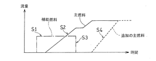
- FIG. 6 shows a fuel flow rate profile when the combustor 3 is operated by such a method.
- the horizontal axis represents time
- the vertical axis represents the fuel flow rate.
- the alternate long and short dash line indicates the flow rate of the auxiliary fuel AF passing through the auxiliary fuel introduction passage 41
- the solid line indicates the flow rate of the main fuel MF passing through the first main fuel introduction passage 43
- the broken line indicates the second main fuel introduction passage 45.
- the flow rate of the additional main fuel MF passing through is shown.
- the auxiliary fuel introduction passage 41 is not provided with a flow rate adjusting valve, and the auxiliary fuel introduction passage 41 is not caused to flow or flow with a predetermined flow rate depending on the combination of the fourth on-off valve 57 and the orifice 59.
- An example of enabling only control is shown.
- the example of the operation method via the auxiliary fuel introduction passage 41 is not limited to this.
- a flow rate adjusting valve is provided downstream of the fourth on-off valve 57 on the auxiliary fuel introduction passage 41 to adjust the flow rate of the auxiliary fuel AF while introducing the auxiliary fuel AF or the auxiliary fuel stop step in the auxiliary fuel ignition step S1.
- the introduction of the auxiliary fuel AF may be stopped in S3.
- the auxiliary fuel AF may be stopped while gradually decreasing the flow rate of the auxiliary fuel AF from the start of injection of the main fuel MF.
- the flow rate of the auxiliary fuel AF is changed from the start time of the injection of the main fuel MF in the auxiliary fuel stop step S ⁇ b> 3. You may stop while decreasing gradually.
- FIG. 9 first, a method for stopping the combustor 3 from a high-load operation state in which the main fuel MF injected into the combustion chamber 11 from the plurality of annular fuel injection units 25 is burning will be described.
- the introduction of the main fuel MF from the second main fuel introduction passage 45 to the auxiliary fuel injection section 25A is stopped (additional main fuel stop step S5).
- the auxiliary fuel AF is injected from the auxiliary fuel introduction passage 41 into the combustion chamber 11 via the auxiliary fuel injection portion 25A (auxiliary fuel reinjection step S6).
- main fuel stop step S7 After the main fuel stop step S7, the supply of the auxiliary fuel AF from the auxiliary fuel introduction passage 41 is stopped (auxiliary fuel final stop step S8). Thereby, the operation of the combustor 3 is stopped.
- steps S5 to S8 are the basic procedure for stopping the operation of the combustor 3. However, when the combustor 3 is stopped, the following steps for purging the main fuel MF may be performed.
- the purge gas PG is supplied from the purge gas introduction passage 61 to the first main fuel introduction passage 43 and the second main fuel introduction passage. 45 (purge gas introduction step S9).
- the purge gas PG is introduced from the purge gas introduction passage 61 into the first main fuel introduction passage 43 and the second main fuel introduction passage 45 through the main fuel main passage 51.
- the additional purge gas introduction passage 63 is used to supply the auxiliary fuel AF from the additional purge gas introduction passage 63 to the first main fuel introduction passage 43 and the second main fuel introduction passage 43. It may be introduced into the fuel introduction passage 45 (additional purge step S11).
- the purging gas introduction step S9 may be omitted, and the additional fuel purging step S10 may be performed thereafter to move to the remaining fuel combustion step S10.
- the purge gas introduction passage 61 and the additional purge gas introduction passage 63 in the combustor 3 By providing the purge gas introduction passage 61 and the additional purge gas introduction passage 63 in the combustor 3 and performing the steps S9 to S11 of purging the main fuel MF using these passages 61 and 63 in the operation method of the combustor 3. Since the main fuel passage can be purged while burning the main fuel MF, the unburned gas of the main fuel having a high reaction speed and a wide combustible concentration range remains in the combustor 3 after stopping. Can be prevented. However, it is not essential to provide the purge passages 61 and 63 and to perform steps S9 to S11 for purging the main fuel MF.
- the fuel is dispersed and injected from the fuel injection holes 25a of the plurality of annular fuel injection sections 25, so that the main fuel MF Even when a highly reactive fuel such as hydrogen gas is used, low NOx combustion can be realized by avoiding the occurrence of locally high temperatures.
- the auxiliary fuel introduction passage 41 is connected to a part of the annular fuel injection parts (auxiliary fuel injection parts 25B) of the plurality of annular fuel injection parts 25 to enable the injection of the auxiliary fuel AF.
- the can-type combustor 3 has been described as an example. However, the above configuration can be applied to other types, for example, an annular combustor.
- Combustor 11 Combustion chamber 13 Combustion cylinder 15
- Fuel injection device 25 Annular fuel injection unit 25A Auxiliary fuel injection unit 25B Main fuel injection unit 35 Second fuel supply path (common fuel supply path) 41 Auxiliary fuel introduction passage 43 First main fuel introduction passage 45 Second main fuel introduction passage 51 First flow regulating valve 61 Purge gas introduction passage 63 Additional purge gas introduction passage AF Auxiliary fuel MF Main fuel P Ignition device
Landscapes
- Engineering & Computer Science (AREA)
- Chemical & Material Sciences (AREA)
- Combustion & Propulsion (AREA)
- Mechanical Engineering (AREA)
- General Engineering & Computer Science (AREA)
Abstract
Provided is a gas turbine combustor (3) equipped with a fuel injection device (15) that has a plurality of annular fuel injection parts (25), each having numerous fuel injection ports (25a) formed therein, the gas turbine combustor being provided with: an auxiliary fuel introduction channel (41) which introduces, into the fuel injection device, an auxiliary fuel (AF) to be supplied to an auxiliary fuel injection part (25A), which is a part of the plurality of annular fuel injection parts (25); a first main fuel introduction channel (43) which is provided with a flow regulating valve (51) and which introduces, into the fuel injection device, a main fuel (MF) to be supplied to main fuel injection parts (25B) which are the annular fuel injection parts other than the auxiliary fuel injection part; and a second main fuel introduction channel (45) which is provided with a flow regulating valve (53) and which introduces, into the fuel injection device, a main fuel (MF) to be supplied to the auxiliary fuel injection part (25A).
Description
本出願は、2017年5月16日出願の特願2017-096984の優先権を主張するものであり、その全体を参照により本願の一部をなすものとして引用する。
This application claims the priority of Japanese Patent Application No. 2017-096984 filed on May 16, 2017, and is incorporated herein by reference in its entirety.
本発明は、ガスタービンエンジンに使用される燃焼器およびその運転方法に関する。
The present invention relates to a combustor used for a gas turbine engine and an operation method thereof.
近年、いわゆる低炭素社会の実現に向けて、燃料に水素を利用するガスタービンエンジンが提案されている。もっとも、水素を含有する燃料のような反応性の高い燃料では、燃焼温度が高くなることからNOxが発生しやすく、これを抑制する必要がある。
In recent years, gas turbine engines that use hydrogen as a fuel have been proposed for the realization of a so-called low-carbon society. However, a highly reactive fuel such as a hydrogen-containing fuel tends to generate NOx because of its high combustion temperature, and it is necessary to suppress this.
水素のような高反応性のガスを燃料として利用しながら、低NOx燃焼を実現するための技術として、多数の燃料噴射孔から燃料を分散させて噴射することにより、局所的な高温燃焼の発生を抑制することが提案されている(例えば、特許文献1参照)。
As a technique for realizing low NOx combustion while using a highly reactive gas such as hydrogen as a fuel, local high temperature combustion is generated by injecting fuel dispersed from many fuel injection holes. Has been proposed (see, for example, Patent Document 1).
しかし、水素燃料のような反応速度が速く、可燃濃度範囲が広い燃料では、エンジン起動時に不着火が発生した際に、可燃ガス(水素と空気の混合気)がエンジン本体および煙道において、異常燃焼する恐れがある。また、上記のように多数の噴射孔から燃料を分散噴射させる場合、水素を含むガスは体積流量が大きいことから、エンジン起動時や停止時ならびに低負荷時運転時、つまり燃焼器に投入される燃料ガス体積流量が小さい場合に、燃料供給分布が不均一化しやすいため、やはり未燃ガスが発生しやすい。
However, in the case of a fuel with a fast reaction speed and a wide flammable concentration range, such as hydrogen fuel, combustible gas (a mixture of hydrogen and air) is abnormal in the engine body and flue when non-ignition occurs at engine startup. There is a risk of burning. In addition, when fuel is dispersedly injected from a large number of injection holes as described above, the gas containing hydrogen has a large volume flow rate, so that it is supplied to the combustor when the engine is started or stopped and during low load operation. When the fuel gas volume flow rate is small, the fuel supply distribution is likely to be non-uniform, so that unburned gas is also likely to be generated.
そこで、本発明の目的は、上記の課題を解決するために、高反応性の燃料を利用するガスタービンエンジンの燃焼器において、低NOx燃焼を実現しながら、エンジン起動時や停止時にも未燃ガスの発生を防止して安定的な作動を維持することにある。
Accordingly, an object of the present invention is to solve the above-mentioned problems, in a gas turbine engine combustor that uses highly reactive fuel, while realizing low NOx combustion, unburned even when the engine is started or stopped. The purpose is to prevent gas generation and maintain stable operation.
上記の課題を解決するために、本発明に係るガスタービン燃焼器は、内側に燃焼室を形成する燃焼筒と、
互いに同心状に配置された複数の環状燃料噴射部を有し、各環状燃料噴射部に周方向に多数配置された燃料噴射孔が形成されており、前記燃焼筒の頂部に設けられている燃料噴射装置と、
前記燃料噴射装置から前記燃焼室へ噴射された燃料に点火する点火装置と、
前記複数の環状燃料噴射部の一部の環状燃料噴射部である補助燃料噴射部に供給される補助燃料を前記燃料噴射装置に導入する補助燃料導入通路と、
前記複数の環状燃料噴射部の前記補助燃料噴射部以外の環状燃料噴射部である主燃料噴射部に供給される主燃料を前記燃料噴射装置に導入する第1主燃料導入通路であって、第1流量調整弁を備える第1主燃料導入通路と、
前記補助燃料噴射部に供給される主燃料を前記燃料噴射装置に導入する第2主燃料導入通路であって、第2流量調整弁を備える第2主燃料導入通路と、
を備えている。
前記主燃料は、例えば水素含有ガスであり、前記補助燃料は、例えば天然ガスである。 In order to solve the above problems, a gas turbine combustor according to the present invention includes a combustion cylinder that forms a combustion chamber inside,
A fuel that has a plurality of annular fuel injection portions arranged concentrically with each other, a plurality of circumferentially arranged fuel injection holes are formed in each annular fuel injection portion, and is provided at the top of the combustion cylinder An injection device;
An ignition device for igniting fuel injected from the fuel injection device into the combustion chamber;
An auxiliary fuel introduction passage for introducing into the fuel injection device auxiliary fuel supplied to an auxiliary fuel injection unit that is an annular fuel injection part of the plurality of annular fuel injection units;
A first main fuel introduction passage that introduces main fuel supplied to a main fuel injection unit that is an annular fuel injection unit other than the auxiliary fuel injection unit of the plurality of annular fuel injection units into the fuel injection device; A first main fuel introduction passage having one flow rate adjustment valve;
A second main fuel introduction passage for introducing main fuel supplied to the auxiliary fuel injection section into the fuel injection device, the second main fuel introduction passage including a second flow rate adjustment valve;
It has.
The main fuel is, for example, a hydrogen-containing gas, and the auxiliary fuel is, for example, natural gas.
この構成によれば、複数の環状燃料噴射部の燃料噴射孔から燃料を分散させて噴射するので、主燃料として高反応性の燃料を使用した場合にも、局所的に高温となる部分が発生することを回避して低NOx燃焼を実現できる。さらに、複数の環状燃料噴射部の一部の環状燃料噴射部に補助燃料導入通路を接続して補助燃料の噴射を可能にしたことにより、補助燃料として主燃料よりも低反応性の燃料を供給して、燃焼器の低負荷状態である起動時や停止時にも安定した燃焼を実現できる。したがって、未燃ガスの発生および未燃ガスの発生による不具合を抑制しながら、燃焼器の安定的な作動およびエンジン運転を維持することができる。
According to this configuration, since fuel is dispersed and injected from the fuel injection holes of the plurality of annular fuel injection portions, even when a highly reactive fuel is used as the main fuel, a locally high temperature portion is generated. This makes it possible to achieve low NOx combustion. Furthermore, the auxiliary fuel introduction passage is connected to some of the annular fuel injection portions to enable the injection of auxiliary fuel, thereby supplying fuel that is less reactive than the main fuel as auxiliary fuel. Thus, stable combustion can be realized even when the combustor is in a low load state at the time of start-up or stop. Therefore, the stable operation of the combustor and the engine operation can be maintained while suppressing the generation of unburned gas and the problems caused by the generation of unburned gas.
本発明の一実施形態に係る燃焼器において、さらに、前記補助燃料噴射部に前記補助燃料および前記主燃料を供給する共通燃料供給路を備え、前記補助燃料導入通路および前記第2主燃料導入通路が、前記共通燃料供給通路に接続されていてもよい。この構成によれば、補助燃料噴射部に対して共通燃料供給通路から補助燃料と主燃料を供給可能とすることにより、燃料噴射装置の構造を簡素化できる。
The combustor according to an embodiment of the present invention may further include a common fuel supply path that supplies the auxiliary fuel and the main fuel to the auxiliary fuel injection unit, and the auxiliary fuel introduction path and the second main fuel introduction path. However, it may be connected to the common fuel supply passage. According to this configuration, the structure of the fuel injection device can be simplified by enabling the auxiliary fuel and the main fuel to be supplied from the common fuel supply passage to the auxiliary fuel injection portion.
本発明の一実施形態に係る燃焼器において、前記点火装置は前記燃焼筒に取り付けられており、前記補助燃料噴射部が、前記複数の環状燃料噴射部のうち最外径側に配置されていてもよい。この構成によれば、補助燃料噴射部を点火装置の近傍に配置することにより、補助燃料に確実に着火することができる。
The combustor which concerns on one Embodiment of this invention WHEREIN: The said ignition device is attached to the said combustion cylinder, and the said auxiliary fuel injection part is arrange | positioned among the some annular fuel injection parts at the outermost diameter side. Also good. According to this configuration, by arranging the auxiliary fuel injection part in the vicinity of the ignition device, the auxiliary fuel can be reliably ignited.
本発明の一実施形態に係る燃焼器において、さらに、前記第1主燃料導入通路および第2主燃料導入通路にパージ用ガスを導入するパージガス導入通路を備えていてもよい。さらには、当該燃焼器が、前記補助燃料導入通路から分岐して前記第1主燃料導入通路および第2主燃料導入通路に前記補助燃料をパージ用ガスとして導入する追加パージガス導入通路を備えていてもよい。この構成によれば、燃焼器の停止時に、専用のパージ用ガスや補助燃料を用いて主燃料通路のパージを、主燃料を燃焼させながら行うことが可能になり、停止後の燃焼器および燃料供給配管に未燃ガスまたは可燃性ガスが残留することを防止できる。
The combustor according to an embodiment of the present invention may further include a purge gas introduction passage for introducing a purge gas into the first main fuel introduction passage and the second main fuel introduction passage. Further, the combustor includes an additional purge gas introduction passage that branches from the auxiliary fuel introduction passage and introduces the auxiliary fuel as a purge gas into the first main fuel introduction passage and the second main fuel introduction passage. Also good. According to this configuration, when the combustor is stopped, the main fuel passage can be purged using the dedicated purge gas or auxiliary fuel while burning the main fuel. It is possible to prevent unburned gas or flammable gas from remaining in the supply pipe.
本発明の第1構成に係るガスタービンエンジン燃焼器の運転方法は、上記燃焼器の起動時における運転方法であって、
起動時に、前記補助燃料を前記補助燃料導入通路から前記補助燃料噴射部を介して前記燃焼室に噴射し、この補助燃料に点火する過程と、
前記補助燃料に着火した後に、前記主燃料を、前記第1主燃料導入通路から前記主燃料噴射部を介して、前記第1流量調整弁によって次第に流量を増加させながら、前記燃焼室に噴射する過程と、
前記主燃料に着火した後に、前記補助燃料導入通路からの補助燃料の導入を停止する過程と、
を含む。 An operation method of the gas turbine engine combustor according to the first configuration of the present invention is an operation method at the time of starting the combustor,
A process of injecting the auxiliary fuel from the auxiliary fuel introduction passage into the combustion chamber through the auxiliary fuel injection unit at the time of start-up,
After the auxiliary fuel is ignited, the main fuel is injected into the combustion chamber from the first main fuel introduction passage through the main fuel injection section while the flow rate is gradually increased by the first flow rate adjusting valve. Process,
A process of stopping the introduction of auxiliary fuel from the auxiliary fuel introduction passage after ignition of the main fuel;
including.
この構成によれば、複数の環状燃料噴射部の一部の環状燃料噴射部から、補助燃料導入通路を介して補助燃料を噴射するので、補助燃料として主燃料よりも低反応性の燃料を供給して、燃焼器の低負荷状態である起動時にも安定した燃焼を実現できる。したがって、未燃ガスの発生および未燃ガスの発生による不具合を抑制しながら、燃焼器の安定的な作動およびエンジン運転を維持することができる。
According to this configuration, since the auxiliary fuel is injected from the annular fuel injection part of the plurality of annular fuel injection parts via the auxiliary fuel introduction passage, fuel having a lower reactivity than the main fuel is supplied as the auxiliary fuel. Thus, stable combustion can be realized even when the combustor is in a low load state. Therefore, the stable operation of the combustor and the engine operation can be maintained while suppressing the generation of unburned gas and the problems caused by the generation of unburned gas.
本発明に係る運転方法の一実施形態において、さらに、前記補助燃料導入通路からの補助燃料の導入を停止した後に、前記主燃料を、前記第2主燃料導入通路から前記補助燃料噴射部を介して、前記第2流量調整弁によって次第に流量を増加させながら、前記燃焼室に噴射する過程を含んでいてもよい。この構成によれば、複数の環状燃料噴射部を備える燃焼器の構造を利用して、負荷の増大に応じて作動させる環状燃料噴射部を増加させるステージング燃焼が可能になる。
In one embodiment of the operation method according to the present invention, after stopping the introduction of auxiliary fuel from the auxiliary fuel introduction passage, the main fuel is supplied from the second main fuel introduction passage through the auxiliary fuel injection unit. In addition, a process of injecting into the combustion chamber while gradually increasing the flow rate by the second flow rate adjusting valve may be included. According to this structure, the staging combustion which increases the annular fuel injection part operated according to the increase in load is attained using the structure of the combustor provided with a plurality of annular fuel injection parts.
本発明の第2構成に係るガスタービンエンジン燃焼器の運転方法は、上記燃焼器の停止時における運転方法であって、
前記複数の環状燃料噴射部から前記燃焼室内に噴射された主燃料が燃焼している高負荷運転状態から、前記第2燃料導入通路から前記補助燃料噴射部への主燃料の導入を停止する過程と、
前記補助燃料噴射部への主燃料の導入を停止した後に、前記補助燃料を前記補助燃料導入通路から前記補助燃料噴射部を介して前記燃焼室に噴射する過程と、
前記補助燃料に着火した後に、前記第1主燃料導入通路からの主燃料の導入を停止する過程と、
前記第1主燃料供給路からの主燃料の導入を停止した後に、前記補助燃料導入通路からの補助燃料の供給を停止する過程とを含む。
なお、補助燃料噴射部から主燃料が噴射されていない低負荷運転状態から停止する場合には、前記補助燃料を前記補助燃料導入通路から前記燃焼室に噴射する過程以降の過程を経て停止を行う。
なお、本明細書において、「停止時」とは、燃焼器の停止に向けた減速運転時を意味する。 An operation method of the gas turbine engine combustor according to the second configuration of the present invention is an operation method when the combustor is stopped,
A process of stopping the introduction of the main fuel from the second fuel introduction passage to the auxiliary fuel injection section from a high-load operation state in which the main fuel injected into the combustion chamber from the plurality of annular fuel injection sections is burning When,
A process of injecting the auxiliary fuel from the auxiliary fuel introduction passage into the combustion chamber via the auxiliary fuel injection section after stopping the introduction of the main fuel into the auxiliary fuel injection section;
After igniting the auxiliary fuel, stopping the introduction of the main fuel from the first main fuel introduction passage;
And a step of stopping the supply of auxiliary fuel from the auxiliary fuel introduction passage after the introduction of main fuel from the first main fuel supply passage is stopped.
In addition, when stopping from the low load operation state where the main fuel is not injected from the auxiliary fuel injection unit, the auxiliary fuel is stopped after the process of injecting the auxiliary fuel from the auxiliary fuel introduction passage into the combustion chamber. .
In the present specification, “when stopped” means when the vehicle is decelerating for stopping the combustor.
この構成によれば、停止時に補助燃料導入通路を介して補助燃料を噴射することによって低負荷状態での安定的な燃焼を確保したうえで、主燃料の供給を停止し、その後補助燃料の噴射を停止するので、停止後に反応速度が速く、可燃濃度範囲が広い主燃料の未燃ガスが残ることを効果的に防止できる。
According to this configuration, the auxiliary fuel is injected through the auxiliary fuel introduction passage during stoppage to ensure stable combustion in a low load state, and then the main fuel supply is stopped, and then the auxiliary fuel injection is performed. Therefore, it is possible to effectively prevent the unburned gas of the main fuel having a high reaction rate and a wide combustible concentration range from remaining after the stop.
本発明の一実施形態に係る運転方法において、前記燃焼器が前記パージガス導入通路を備える場合、さらに、前記第1主燃料導入通路からの主燃料の供給を停止した後に、前記パージガス導入通路からパージ用ガスを前記第1主燃料導入通路および前記第2主燃料導入通路に導入する過程と、前記パージ用ガスの導入によって前記第1主燃料導入通路および前記第2主燃料導入通路から前記燃焼室へ排出された前記主燃料を、前記補助燃料導入通路からの補助燃料と共に燃焼させる過程とを含んでいてもよい。
In the operating method according to an embodiment of the present invention, when the combustor includes the purge gas introduction passage, the purge from the purge gas introduction passage is further stopped after the supply of the main fuel from the first main fuel introduction passage is stopped. A process of introducing a working gas into the first main fuel introducing passage and the second main fuel introducing passage, and introduction of the purge gas from the first main fuel introducing passage and the second main fuel introducing passage into the combustion chamber. And combusting the main fuel discharged to the main fuel together with the auxiliary fuel from the auxiliary fuel introduction passage.
本発明の一実施形態に係る運転方法において、前記燃焼器が前記パージガス導入通路および追加パージガス導入通路を備える場合、さらに、前記パージ用ガスの導入によって前記第1主燃料導入通路および前記第2主燃料導入通路から前記主燃料を前記燃焼室へ排出した後に、前記追加パージガス導入通路から補助燃料を前記第1主燃料導入通路および前記第2主燃料導入通路に導入する過程を含んでいてもよい。
なお、パージ用ガスの導入を経ずに、直接追加パージガスの導入を行ってもよい。 In the operation method according to an embodiment of the present invention, when the combustor includes the purge gas introduction passage and the additional purge gas introduction passage, the first main fuel introduction passage and the second main fuel introduction passage are further introduced by introducing the purge gas. A step of introducing auxiliary fuel from the additional purge gas introduction passage into the first main fuel introduction passage and the second main fuel introduction passage after discharging the main fuel from the fuel introduction passage into the combustion chamber may be included. .
Note that the additional purge gas may be directly introduced without introducing the purge gas.
この構成によれば、燃焼器の停止時に、専用のパージ用ガスや補助燃料を用いて、主燃料通路のパージを、主燃料を燃焼させながら行うので、停止後の燃焼器および燃料供給配管に、反応速度が速く、可燃濃度範囲が広い主燃料の未燃ガスが残留することを防止できる。
According to this configuration, when the combustor is stopped, the main fuel passage is purged while burning the main fuel using a dedicated purge gas or auxiliary fuel. Therefore, the combustor and the fuel supply pipe after the stop are used. It is possible to prevent the unburned gas of the main fuel having a high reaction rate and a wide flammable concentration range from remaining.
請求の範囲および/または明細書および/または図面に開示された少なくとも2つの構成のどのような組合せも、本発明に含まれる。特に、請求の範囲の各請求項の2つ以上のどのような組合せも、本発明に含まれる。
Any combination of at least two configurations disclosed in the claims and / or the specification and / or drawings is included in the present invention. In particular, any combination of two or more of each claim in the claims is included in the present invention.
この発明は、添付の図面を参考にした以下の好適な実施形態の説明から、より明瞭に理解されるであろう。しかしながら、実施形態および図面は単なる図示および説明のためのものであり、この発明の範囲を定めるために利用されるべきものではない。この発明の範囲は添付の請求の範囲によって定まる。添付図面において、複数の図面における同一の符号は、同一または相当する部分を示す。
本発明の一実施形態に係る燃料噴射装置が適用されるガスタービンエンジンの概略構成を示すブロック図である。
本発明の一実施形態に係る燃焼器を示す断面図である。
図2の燃焼器に使用される燃料噴射装置の例を示す正面図である。
図2の燃焼器に使用される燃料導入系統の例を模式的に示すブロック図である。
図2の燃焼器の起動時における運転方法の一例を示すフロー図である。
図5の運転方法による燃料流量プロファイルの一例を模式的に示すグラフである。
図5の運転方法による燃料流量プロファイルの他の例を模式的に示すグラフである。
図5の運転方法による燃料流量プロファイルの他の例を模式的に示すグラフである。
図2の燃焼器の停止時における運転方法の一例を示すフロー図である。
The present invention will be more clearly understood from the following description of preferred embodiments with reference to the accompanying drawings. However, the embodiments and drawings are for illustration and description only and should not be used to define the scope of the present invention. The scope of the invention is defined by the appended claims. In the accompanying drawings, the same reference numerals in a plurality of drawings indicate the same or corresponding parts.
1 is a block diagram showing a schematic configuration of a gas turbine engine to which a fuel injection device according to an embodiment of the present invention is applied. It is sectional drawing which shows the combustor which concerns on one Embodiment of this invention. It is a front view which shows the example of the fuel-injection apparatus used for the combustor of FIG. It is a block diagram which shows typically the example of the fuel introduction system | strain used for the combustor of FIG. It is a flowchart which shows an example of the operation method at the time of starting of the combustor of FIG. It is a graph which shows typically an example of the fuel flow rate profile by the operation method of FIG. 6 is a graph schematically showing another example of a fuel flow rate profile according to the operation method of FIG. 5. 6 is a graph schematically showing another example of a fuel flow rate profile according to the operation method of FIG. 5. It is a flowchart which shows an example of the operating method at the time of the stop of the combustor of FIG.
以下、本発明に係る実施形態を図面に従って説明するが、本発明は本実施形態に限定されるものではない。
Hereinafter, embodiments according to the present invention will be described with reference to the drawings. However, the present invention is not limited to the embodiments.
図1に、本発明の一実施形態に係る燃焼器が適用されるガスタービンエンジン(以下、単にガスタービンと称する。)GTの概略構成を示す。ガスタービンGTは、導入した空気を圧縮機1で圧縮して燃焼器3に導き、燃料を燃焼器3内に噴射して燃焼させ、得られた高温高圧の燃焼ガスGによりタービン5を駆動する。燃焼器3は、例えば、ガスタービンGTの軸心の周りに環状に複数個配置されるキャン型の燃焼器である。タービン5は圧縮機1に回転軸7を介して連結されており、タービン5によって圧縮機1が駆動される。このガスタービンGTの出力により、航空機のロータまたは発電機などの負荷Lを駆動する。以下の説明において、ガスタービンGTの軸心方向における圧縮機1側を「前側」と呼び、タービン5側を「後側」と呼ぶ。
FIG. 1 shows a schematic configuration of a gas turbine engine (hereinafter simply referred to as a gas turbine) GT to which a combustor according to an embodiment of the present invention is applied. The gas turbine GT compresses the introduced air by the compressor 1 and guides it to the combustor 3, injects the fuel into the combustor 3 and burns it, and drives the turbine 5 by the obtained high-temperature and high-pressure combustion gas G. . The combustor 3 is, for example, a can-type combustor that is arranged in a ring shape around the axis of the gas turbine GT. The turbine 5 is connected to the compressor 1 via the rotary shaft 7, and the compressor 1 is driven by the turbine 5. A load L such as an aircraft rotor or a generator is driven by the output of the gas turbine GT. In the following description, the compressor 1 side in the axial direction of the gas turbine GT is referred to as “front side”, and the turbine 5 side is referred to as “rear side”.
図2に示すように、燃焼器3は、内側に燃焼室11を形成する燃焼筒13と、燃焼筒13の頂部(最上流部)13aに取り付けられて燃焼室11に燃料と空気を噴射する燃料噴射装置15と、燃料噴射装置15に燃料を導入する燃料供給系統ISとを備えている。燃料噴射装置15から噴射された燃料と空気に、燃焼筒13に設けられた点火装置Pで点火することにより、燃焼室11内に火炎が形成される。これら燃焼筒13および燃料噴射装置15は、燃焼器3の外筒となるほぼ円筒状のハウジングHに同心状に収容されている。
As shown in FIG. 2, the combustor 3 is attached to a combustion cylinder 13 that forms a combustion chamber 11 on the inner side, and a top (most upstream part) 13 a of the combustion cylinder 13, and injects fuel and air into the combustion chamber 11. A fuel injection device 15 and a fuel supply system IS for introducing fuel into the fuel injection device 15 are provided. A flame is formed in the combustion chamber 11 by igniting the fuel and air injected from the fuel injection device 15 with an ignition device P provided in the combustion cylinder 13. The combustion cylinder 13 and the fuel injection device 15 are concentrically accommodated in a substantially cylindrical housing H that is an outer cylinder of the combustor 3.
本実施形態では、燃焼器3は空気Aの流動方向と燃焼ガスGの流動方向とが逆向きの逆流型として構成されている。すなわち、燃焼器3は、ハウジングHと燃焼筒13および燃焼筒13から前方へ筒状に延びる支持筒17との間に形成された空気導入通路19を有しており、この空気導入通路19は、圧縮機1(図1)で圧縮された空気Aを、燃焼室11内の燃焼ガスGの流動方向と逆方向に導く。なお、燃焼器3は、空気Aと燃焼ガスGとの流動方向が同じ向きの軸流型であってもよい。支持筒17の周壁の前端部には、複数の空気導入孔21が周方向に並べて設けられている。空気導入通路19を通って送られてきた空気Aは、空気導入孔21を通って、支持筒17の内方に形成された空気供給通路23に導入され、後方、すなわち燃焼室11の方向へ送られる。
In this embodiment, the combustor 3 is configured as a reverse flow type in which the flow direction of the air A and the flow direction of the combustion gas G are opposite to each other. In other words, the combustor 3 has an air introduction passage 19 formed between the housing H and the combustion cylinder 13 and the support cylinder 17 extending forward from the combustion cylinder 13. The air A compressed by the compressor 1 (FIG. 1) is guided in the direction opposite to the flow direction of the combustion gas G in the combustion chamber 11. The combustor 3 may be an axial flow type in which the flow directions of the air A and the combustion gas G are the same. A plurality of air introduction holes 21 are arranged in the circumferential direction at the front end of the peripheral wall of the support cylinder 17. The air A sent through the air introduction passage 19 is introduced into the air supply passage 23 formed inside the support cylinder 17 through the air introduction hole 21, and rearward, that is, toward the combustion chamber 11. Sent.
図3に示すように、燃料噴射装置15は、複数の環状燃料噴射部25を備えている。本実施形態では、径寸法が互いに異なる3つの環状燃料噴射部25が、互いに同心状に、かつ燃焼器3(図2)と同心状に配置されている。各環状燃料噴射部25には、その周方向に等間隔に多数配置された燃料噴射孔25aが形成されている。図2に示すように、例えば、各環状燃料噴射部25の径方向外側および内側に、空気供給通路23からの空気Aをガイドし、環状燃料噴射部25から噴射された燃料と空気を混合するための空気ガイド27が配置されている。各環状燃料噴射部25から噴射された燃料は、空気ガイド27でガイドされた空気と予混合され、予混合気として燃焼室11へ噴射される。なお、環状燃料噴射部25の数は、2つ以上であれば、特に限定されない。
As shown in FIG. 3, the fuel injection device 15 includes a plurality of annular fuel injection units 25. In the present embodiment, three annular fuel injection portions 25 having different diameters are arranged concentrically with each other and with the combustor 3 (FIG. 2). Each annular fuel injection portion 25 is formed with a plurality of fuel injection holes 25a arranged at equal intervals in the circumferential direction. As shown in FIG. 2, for example, the air A from the air supply passage 23 is guided on the radially outer side and the inner side of each annular fuel injection portion 25 to mix the fuel and air injected from the annular fuel injection portion 25. An air guide 27 is provided. The fuel injected from each annular fuel injection section 25 is premixed with the air guided by the air guide 27 and injected into the combustion chamber 11 as a premixed gas. The number of annular fuel injection portions 25 is not particularly limited as long as it is two or more.
次に、燃焼器3の燃料噴射装置15における具体的な燃料供給構造について説明する。本実施形態の燃焼器3は、燃料噴射装置15の各環状燃料噴射部25に燃料Fを供給可能な複数の燃料供給路を有している。燃料噴射装置15には、空気供給通路23の中心部からハウジングHの後方へかけて延びる燃料供給母管29が設けられている。燃料供給母管29と各環状燃料噴射部25とは、互いに独立に分岐する分岐燃料供給管31によって接続されている。燃料供給母管29は、2つの円筒管を同心状に重ねた多管式構造(二重管構造)を有している。内側の燃料供給管の内方空間およびこれに連通する分岐燃料供給管31の内方空間が、第1燃料供給路33を形成し、内外の燃料供給管の間の空間およびこれに連通する分岐燃料供給管31の内方空間が、第2燃料供給路35を形成している。燃料供給母管29内の各燃料供給路33,35には、後述する燃料導入系統ISから燃料が導入される。
Next, a specific fuel supply structure in the fuel injection device 15 of the combustor 3 will be described. The combustor 3 of the present embodiment has a plurality of fuel supply paths that can supply the fuel F to each annular fuel injection section 25 of the fuel injection device 15. The fuel injection device 15 is provided with a fuel supply pipe 29 that extends from the center of the air supply passage 23 to the rear of the housing H. The fuel supply mother pipe 29 and each annular fuel injection section 25 are connected by a branched fuel supply pipe 31 that branches independently from each other. The fuel supply mother pipe 29 has a multitubular structure (double pipe structure) in which two cylindrical pipes are concentrically stacked. The inner space of the inner fuel supply pipe and the inner space of the branch fuel supply pipe 31 communicating therewith form the first fuel supply path 33, and the space between the inner and outer fuel supply pipes and the branch communicating therewith An inner space of the fuel supply pipe 31 forms a second fuel supply path 35. Fuel is introduced into the fuel supply passages 33 and 35 in the fuel supply pipe 29 from a fuel introduction system IS described later.
本実施形態では、第1燃料供給路33を通った燃料は、複数の環状燃料噴射部25のうちの内径側に配置された2つの環状燃料噴射部25へ供給される。第2燃料供給路35を通った燃料Fは、第2燃料供給路35に接続された1つの分岐燃料供給管31を介して、複数の環状燃料噴射部25のうち最外径側に配置された1つの環状燃料噴射部25へ供給される。
In the present embodiment, the fuel that has passed through the first fuel supply path 33 is supplied to the two annular fuel injection units 25 arranged on the inner diameter side of the plurality of annular fuel injection units 25. The fuel F that has passed through the second fuel supply path 35 is disposed on the outermost diameter side of the plurality of annular fuel injection sections 25 via one branch fuel supply pipe 31 connected to the second fuel supply path 35. Is supplied to the single annular fuel injection section 25.
なお、燃料供給母管29の多管式構造は、複数の管を用いて互いに独立した複数の燃料供給路を形成できるのであれば、図2の例に限らない。例えば、1つの大径の母管の中に、これより小径の同一径の複数の燃料供給管を平行に延設した多管式構造でもよい。
The multi-tubular structure of the fuel supply mother pipe 29 is not limited to the example of FIG. 2 as long as a plurality of fuel supply paths independent of each other can be formed using a plurality of pipes. For example, a multi-tubular structure in which a plurality of fuel supply pipes having the same diameter smaller than this and extending in parallel in one large-diameter mother pipe may be used.
このような燃料供給構造とすることにより、ガスタービンGTの低負荷(部分負荷)から高負荷(定格負荷)までの出力変化に対して、燃料供給を行う環状燃料噴射部25と燃料供給を行わない環状燃料噴射部25とに分けることにより対応するステージング燃焼が可能となる。本実施形態のように、燃料を燃料噴射装置15の複数の環状燃料噴射部25の多数の燃料噴射孔25aに分散させて噴射する場合には、すべての環状燃料噴射部25において均一的に燃料供給量を変化させるよりも、作動させる環状燃料噴射部25と作動させない環状燃料噴射部25を選択することによって負荷変動に対応することが、安定的かつ低NOx燃焼のために効果的である。
By adopting such a fuel supply structure, the annular fuel injection unit 25 that supplies fuel and the fuel supply are performed with respect to an output change from a low load (partial load) to a high load (rated load) of the gas turbine GT. The corresponding staging combustion becomes possible by dividing into the annular fuel injection section 25 which is not. When the fuel is dispersed and injected into the multiple fuel injection holes 25a of the plurality of annular fuel injection units 25 of the fuel injection device 15 as in the present embodiment, the fuel is uniformly distributed in all the annular fuel injection units 25. It is more effective for stable and low NOx combustion to cope with the load fluctuation by selecting the annular fuel injection section 25 to be operated and the annular fuel injection section 25 not to be operated than to change the supply amount.
次に、このような構造を有する燃料噴射装置15に対して燃料を導入する燃料導入系統ISの構成について説明する。図4に示すように、本実施形態において、燃料導入系統ISは、補助燃料導入通路41、第1主燃料導入通路43および第2主燃料導入通路45を備えている。補助燃料導入通路41は、補助燃料源47から補助燃料AFを燃料噴射装置15に導入する。第1主燃料導入通路43および第2主燃料導入通路45は、主燃料源49からの主燃料を燃料噴射装置15に導入する。図示の例では、第1主燃料導入通路43と第2主燃料導入通路45とは、共通の主燃料源49に接続する共通の主燃料基幹通路51に接続している。換言すれば、第1主燃料導入通路43および第2主燃料導入通路45は、主燃料基幹通路51の下流端から分岐して設けられている。なお、第1主燃料導入通路43と第2主燃料導入通路45とは、別個に設けられた主燃料源にそれぞれ独立に接続されていてもよい。
Next, the configuration of the fuel introduction system IS that introduces fuel to the fuel injection device 15 having such a structure will be described. As shown in FIG. 4, in the present embodiment, the fuel introduction system IS includes an auxiliary fuel introduction passage 41, a first main fuel introduction passage 43, and a second main fuel introduction passage 45. The auxiliary fuel introduction passage 41 introduces auxiliary fuel AF from the auxiliary fuel source 47 to the fuel injection device 15. The first main fuel introduction passage 43 and the second main fuel introduction passage 45 introduce main fuel from the main fuel source 49 into the fuel injection device 15. In the illustrated example, the first main fuel introduction passage 43 and the second main fuel introduction passage 45 are connected to a common main fuel main passage 51 connected to a common main fuel source 49. In other words, the first main fuel introduction passage 43 and the second main fuel introduction passage 45 are branched from the downstream end of the main fuel main passage 51. The first main fuel introduction passage 43 and the second main fuel introduction passage 45 may be independently connected to main fuel sources provided separately.
補助燃料導入通路41は、第1主燃料導入通路43複数の環状燃料噴射部25のうち最外径側に配置された環状燃料噴射部25(以下、「補助燃料噴射部25A」と呼ぶ。)に供給される補助燃料AFを燃料噴射装置15に導入する。第1主燃料導入通路43は、複数の環状燃料噴射部25のうち、補助燃料噴射部25A以外の環状燃料噴射部25、つまり内径側に配置された2つの環状燃料噴射部25(以下、「主燃料噴射部25B」と呼ぶ。)に供給される主燃料を燃料噴射装置15に導入する。第2主燃料導入通路45は、補助燃料噴射部25Aに供給される主燃料MFを燃料噴射装置15に導入する。すなわち、本実施形態においては、補助燃料導入通路41および第2主燃料導入通路45が、燃料噴射装置15の第2燃料供給路35に接続しており、第2燃料供給路35は補助燃料噴射部25Aへの補助燃料AFの供給通路と主燃料MFの供給通路とを兼ねる共通燃料供給路として形成されている。また、第1主燃料導入通路43は、燃料噴射装置15の第1燃料供給路33に接続しており、第1燃料供給路33を介して2つの主燃料噴射部25Bに主燃料MFを供給する。
The auxiliary fuel introduction passage 41 is an annular fuel injection portion 25 disposed on the outermost diameter side among the plurality of annular fuel injection portions 25 (hereinafter referred to as “auxiliary fuel injection portion 25A”). The auxiliary fuel AF supplied to is introduced into the fuel injection device 15. The first main fuel introduction passage 43 has an annular fuel injection section 25 other than the auxiliary fuel injection section 25A among the plurality of annular fuel injection sections 25, that is, two annular fuel injection sections 25 (hereinafter, “ Main fuel supplied to the main fuel injection section 25B ”) is introduced into the fuel injection device 15. The second main fuel introduction passage 45 introduces the main fuel MF supplied to the auxiliary fuel injection unit 25 </ b> A into the fuel injection device 15. That is, in the present embodiment, the auxiliary fuel introduction passage 41 and the second main fuel introduction passage 45 are connected to the second fuel supply passage 35 of the fuel injection device 15, and the second fuel supply passage 35 is connected to the auxiliary fuel injection. It is formed as a common fuel supply path that serves as a supply path for the auxiliary fuel AF to the portion 25A and a supply path for the main fuel MF. The first main fuel introduction passage 43 is connected to the first fuel supply passage 33 of the fuel injection device 15, and supplies the main fuel MF to the two main fuel injection portions 25B via the first fuel supply passage 33. To do.
なお、本実施形態では、図2に示すように、点火装置Pが燃焼筒13に取り付けられており、補助燃料噴射部25Aが複数の環状燃料噴射部25のうち最外径側に配置されているので、補助燃料噴射部25Aが点火装置Pの近傍に位置し、補助燃料に確実に着火することができる。もっとも、点火装置Pおよび補助燃料噴射部25Aの配置はこの例に限定されない。例えば、点火装置を燃焼器3の軸心C上に配置した場合には、複数の環状燃料噴射部25のうち最内径側に配置された環状燃料噴射部を補助燃料噴射部25Aとしてもよい(つまり、補助燃料導入通路41からの補助燃料AFの供給および第2主燃料導入通路45からの主燃料MFの供給を受けるように構成してもよい)。また、補助燃料噴射部25Aは必ずしも点火装置Pの近傍に配置しなくてもよい。また、補助燃料噴射部25Aの数は、複数の環状燃料噴射部25の全部でない限り、1つに限定されず、2つ以上であってよい。
In the present embodiment, as shown in FIG. 2, the ignition device P is attached to the combustion cylinder 13, and the auxiliary fuel injection portion 25 </ b> A is disposed on the outermost diameter side among the plurality of annular fuel injection portions 25. Therefore, the auxiliary fuel injection portion 25A is positioned in the vicinity of the ignition device P, and the auxiliary fuel can be ignited with certainty. However, the arrangement of the ignition device P and the auxiliary fuel injection unit 25A is not limited to this example. For example, when the ignition device is arranged on the axis C of the combustor 3, the annular fuel injection part arranged on the innermost diameter side among the plurality of annular fuel injection parts 25 may be used as the auxiliary fuel injection part 25A ( In other words, the auxiliary fuel AF may be supplied from the auxiliary fuel introduction passage 41 and the main fuel MF from the second main fuel introduction passage 45. Further, the auxiliary fuel injection unit 25A is not necessarily arranged in the vicinity of the ignition device P. Further, the number of auxiliary fuel injection units 25A is not limited to one as long as it is not a whole of the plurality of annular fuel injection units 25, and may be two or more.
主燃料MFは、反応性が高く、可燃濃度範囲が広い燃料であり、本実施形態では、主燃料MFは水素含有ガス、例えば水素ガスである。補助燃料AFは、主燃料MFよりも反応性が低く、可燃濃度範囲が狭い燃料であり、燃焼器の起動時のほか、後述するように燃焼器の停止時のような低負荷時に利用することができる。本実施形態では、補助燃料AFは天然ガスである。補助燃料AFとしては、天然ガスのほかに、例えば、プロパン等の炭化水素燃料ガスを使用することができる。
The main fuel MF is a fuel having high reactivity and a wide flammable concentration range. In the present embodiment, the main fuel MF is a hydrogen-containing gas, for example, hydrogen gas. The auxiliary fuel AF is less reactive than the main fuel MF and has a narrow flammable concentration range. The auxiliary fuel AF should be used not only when the combustor is started but also when the load is low such as when the combustor is stopped as will be described later. Can do. In the present embodiment, the auxiliary fuel AF is natural gas. As the auxiliary fuel AF, for example, hydrocarbon fuel gas such as propane can be used in addition to natural gas.
図4に示すように、第1主燃料導入通路43および第2主燃料導入通路45には、それぞれ、上流部に開閉弁(第1開閉弁47および第2開閉弁49)が設けられており、その下流に流量調整弁(第1流量調整弁51および第2流量調整弁53)が設けられている。主燃料基幹通路51には、開閉弁(第3開閉弁55)が設けられている。また、補助燃料導入通路41の上流部には、開閉弁(第4開閉弁57)が設けられており、その下流に流量制限用のオリフィス59が設けられている。
As shown in FIG. 4, the first main fuel introduction passage 43 and the second main fuel introduction passage 45 are each provided with an on-off valve (first on-off valve 47 and second on-off valve 49) in the upstream portion. The flow rate adjusting valves (the first flow rate adjusting valve 51 and the second flow rate adjusting valve 53) are provided downstream thereof. The main fuel trunk passage 51 is provided with an on-off valve (third on-off valve 55). Further, an on-off valve (fourth on-off valve 57) is provided upstream of the auxiliary fuel introduction passage 41, and an orifice 59 for restricting the flow rate is provided downstream thereof.
さらに、燃料導入系統ISは、第1主燃料導入通路43および第2主燃料導入通路45にパージ用ガスPGを導入するパージガス導入通路61を備えている。第1主燃料導入通路43および第2主燃料導入通路45が主燃料基幹通路51から分岐している本実施形態では、パージガス導入通路61は、主燃料基幹通路51の第3開閉弁55の下流部分に接続している。また、燃料導入系統ISは、補助燃料導入通路41から分岐して第1主燃料導入通路43および第2主燃料導入通路45に補助燃料AFをパージ用のガスとして導入する追加パージガス導入通路63を備えている。本実施形態では、追加パージガス導入通路63も、主燃料基幹通路51の第3開閉弁55の下流部分に接続している。
The fuel introduction system IS further includes a purge gas introduction passage 61 for introducing the purge gas PG into the first main fuel introduction passage 43 and the second main fuel introduction passage 45. In the present embodiment in which the first main fuel introduction passage 43 and the second main fuel introduction passage 45 are branched from the main fuel main passage 51, the purge gas introduction passage 61 is downstream of the third on-off valve 55 of the main fuel main passage 51. Connected to the part. Further, the fuel introduction system IS has an additional purge gas introduction passage 63 that branches from the auxiliary fuel introduction passage 41 and introduces the auxiliary fuel AF as a purge gas into the first main fuel introduction passage 43 and the second main fuel introduction passage 45. I have. In the present embodiment, the additional purge gas introduction passage 63 is also connected to the downstream portion of the third on-off valve 55 of the main fuel main passage 51.
なお、パージ用ガスPGとしては、例えば、反応性の極めて低い窒素ガスや、不活性ガスなどを使用することができる。パージ用ガスPGは、パージガス導入通路61に接続されたパージガス源65から供給される。
In addition, as the purge gas PG, for example, nitrogen gas having an extremely low reactivity, an inert gas, or the like can be used. The purge gas PG is supplied from a purge gas source 65 connected to the purge gas introduction passage 61.
次に、このように構成された燃焼器3の運転方法について説明する。まず、燃焼器3の起動時の運転方法について説明する。
Next, an operation method of the combustor 3 configured as described above will be described. First, an operation method when the combustor 3 is started will be described.
図5に示すように、燃焼器3の起動時には、まず、補助燃料AFを補助燃料導入通路41から、第2燃料供給路35および補助燃料噴射部25Aを介して燃焼室11に噴射し、燃焼室11に噴射された補助燃料AFに、点火装置P(図2)によって点火する(補助燃料点火ステップS1)。補助燃料AFに着火した後に、主燃料MFを、第1主燃料導入通路43から主燃料噴射部25Bを介して、第1流量調整弁51(図4)によって次第に流量を増加させながら、燃焼室11に噴射する(主燃料噴射ステップS2)。主燃料MFに着火した後に、補助燃料導入通路41からの補助燃料AFの導入を停止する(補助燃料停止ステップS3)。
As shown in FIG. 5, when the combustor 3 is started, first, the auxiliary fuel AF is injected from the auxiliary fuel introduction passage 41 into the combustion chamber 11 via the second fuel supply passage 35 and the auxiliary fuel injection portion 25A, and combustion is performed. The auxiliary fuel AF injected into the chamber 11 is ignited by the ignition device P (FIG. 2) (auxiliary fuel ignition step S1). After the auxiliary fuel AF is ignited, the main fuel MF is gradually increased in flow rate by the first flow rate adjusting valve 51 (FIG. 4) from the first main fuel introduction passage 43 through the main fuel injection section 25B. 11 (main fuel injection step S2). After the main fuel MF is ignited, the introduction of the auxiliary fuel AF from the auxiliary fuel introduction passage 41 is stopped (auxiliary fuel stop step S3).
この燃焼器3が使用されるガスタービンの定格運転よりも低い負荷で運転する場合(低負荷運転状態)においては、この状態で運転を継続する。
When operating at a load lower than the rated operation of the gas turbine in which this combustor 3 is used (low load operation state), the operation is continued in this state.
上記低負荷運転状態よりも高負荷の、例えばガスタービンの定格運転を行う場合(高負荷運転状態)においては、補助燃料停止ステップS3の後に、追加の主燃料MFを、第2主燃料導入通路45から補助燃料噴射部25Aを介して、第2流量調整弁53(図4)によって次第に流量を増加させながら、燃焼室11に噴射する(追加主燃料噴射ステップS4)。
In the case where the rated operation of the gas turbine, for example, in which the load is higher than that in the low load operation state (high load operation state), the additional main fuel MF is supplied to the second main fuel introduction passage after the auxiliary fuel stop step S3. The fuel is injected into the combustion chamber 11 from 45 through the auxiliary fuel injection section 25A while the flow rate is gradually increased by the second flow rate adjusting valve 53 (FIG. 4) (additional main fuel injection step S4).
このような方法で燃焼器3を運転する場合の燃料流量のプロファイルを図6に示す。同図において、横軸が時間を、縦軸が燃料の流量を示す。また、一点鎖線が補助燃料導入通路41を通過する補助燃料AFの流量を示し、実線が第1主燃料導入通路43を通過する主燃料MFの流量を示し、破線が第2主燃料導入通路45を通過する追加の主燃料MFの流量を示す。なお、本実施形態では、補助燃料導入通路41に流量調整弁を設けず、第4開閉弁57とオリフィス59の組合せによって、補助燃料導入通路41に所定の流量の補助燃料AFを流すか流さないかのみの制御を可能とした例を示した。しかし、補助燃料導入通路41を介した運転方法の例はこれに限定されない。例えば、補助燃料導入通路41上の第4開閉弁57の下流に流量調整弁を設けて、補助燃料AFの流量を調整しながら、補助燃料点火ステップS1における補助燃料AFの導入や補助燃料停止ステップS3における補助燃料AFの導入停止を行ってもよい。この場合、例えば、図7に示すように、補助燃料停止ステップS3において、主燃料MFの噴射開始時点から、補助燃料AFの流量を次第に減少させながら停止してもよい。あるいは、図8に示すように、補助燃料点火ステップS1において、補助燃料AFの流量を次第に増加させた後、補助燃料停止ステップS3において、主燃料MFの噴射開始時点から、補助燃料AFの流量を次第に減少させながら停止してもよい。
FIG. 6 shows a fuel flow rate profile when the combustor 3 is operated by such a method. In the figure, the horizontal axis represents time, and the vertical axis represents the fuel flow rate. The alternate long and short dash line indicates the flow rate of the auxiliary fuel AF passing through the auxiliary fuel introduction passage 41, the solid line indicates the flow rate of the main fuel MF passing through the first main fuel introduction passage 43, and the broken line indicates the second main fuel introduction passage 45. The flow rate of the additional main fuel MF passing through is shown. In the present embodiment, the auxiliary fuel introduction passage 41 is not provided with a flow rate adjusting valve, and the auxiliary fuel introduction passage 41 is not caused to flow or flow with a predetermined flow rate depending on the combination of the fourth on-off valve 57 and the orifice 59. An example of enabling only control is shown. However, the example of the operation method via the auxiliary fuel introduction passage 41 is not limited to this. For example, a flow rate adjusting valve is provided downstream of the fourth on-off valve 57 on the auxiliary fuel introduction passage 41 to adjust the flow rate of the auxiliary fuel AF while introducing the auxiliary fuel AF or the auxiliary fuel stop step in the auxiliary fuel ignition step S1. The introduction of the auxiliary fuel AF may be stopped in S3. In this case, for example, as shown in FIG. 7, in the auxiliary fuel stop step S <b> 3, the auxiliary fuel AF may be stopped while gradually decreasing the flow rate of the auxiliary fuel AF from the start of injection of the main fuel MF. Alternatively, as shown in FIG. 8, after the flow rate of the auxiliary fuel AF is gradually increased in the auxiliary fuel ignition step S <b> 1, the flow rate of the auxiliary fuel AF is changed from the start time of the injection of the main fuel MF in the auxiliary fuel stop step S <b> 3. You may stop while decreasing gradually.
次に、燃焼器3の停止時の運転方法について説明する。図9に示すように、まず、複数の環状燃料噴射部25から燃焼室11内に噴射された主燃料MFが燃焼している高負荷運転状態から燃焼器3を停止する方法について説明する。高負荷運転状態において、第2主燃料導入通路45から補助燃料噴射部25Aへの主燃料MFの導入を停止する(追加主燃料停止ステップS5)。追加主燃料停止ステップS5の後、補助燃料AFを補助燃料導入通路41から補助燃料噴射部25Aを介して燃焼室11に噴射する(補助燃料再噴射ステップS6)。補助燃料再噴射ステップS6によって噴射された補助燃料AFに着火した後に、第1主燃料導入通路43からの主燃料MFの導入を停止する(主燃料停止ステップS7)。主燃料停止ステップS7の後に、補助燃料導入通路41からの補助燃料AFの供給を停止する(補助燃料最終停止ステップS8)。これにより、燃焼器3の運転が停止される。
Next, an operation method when the combustor 3 is stopped will be described. As shown in FIG. 9, first, a method for stopping the combustor 3 from a high-load operation state in which the main fuel MF injected into the combustion chamber 11 from the plurality of annular fuel injection units 25 is burning will be described. In the high load operation state, the introduction of the main fuel MF from the second main fuel introduction passage 45 to the auxiliary fuel injection section 25A is stopped (additional main fuel stop step S5). After the additional main fuel stop step S5, the auxiliary fuel AF is injected from the auxiliary fuel introduction passage 41 into the combustion chamber 11 via the auxiliary fuel injection portion 25A (auxiliary fuel reinjection step S6). After the auxiliary fuel AF injected in the auxiliary fuel reinjection step S6 is ignited, the introduction of the main fuel MF from the first main fuel introduction passage 43 is stopped (main fuel stop step S7). After the main fuel stop step S7, the supply of the auxiliary fuel AF from the auxiliary fuel introduction passage 41 is stopped (auxiliary fuel final stop step S8). Thereby, the operation of the combustor 3 is stopped.
複数の環状燃料噴射部25のうち主燃料噴射部25Bのみから主燃料MFが燃焼室11内に噴射されており、この主燃料MFが燃焼している低負荷運転状態においては、上記追加主燃料停止ステップS5を除いたステップS6~S8によって燃焼器3の作動を停止する。
In the low load operation state in which the main fuel MF is injected into the combustion chamber 11 from only the main fuel injection unit 25B among the plurality of annular fuel injection units 25, the additional main fuel is added. The operation of the combustor 3 is stopped by steps S6 to S8 excluding the stop step S5.
上記ステップS5~S8が燃焼器3の作動を停止するための基本的な手順であるが、燃焼器3の停止時に、さらに、主燃料MFをパージするための以下のステップを行ってもよい。
The above steps S5 to S8 are the basic procedure for stopping the operation of the combustor 3. However, when the combustor 3 is stopped, the following steps for purging the main fuel MF may be performed.
第1主燃料導入通路43からの主燃料MFの供給を停止した(主燃料停止ステップS7)後に、パージガス導入通路61からパージ用ガスPGを第1主燃料導入通路43および第2主燃料導入通路45に導入する(パージ用ガス導入ステップS9)。なお、本実施形態では、パージ用ガスPGをパージガス導入通路61から主燃料基幹通路51を介して第1主燃料導入通路43および第2主燃料導入通路45に導入する。その後、パージ用ガスPGの導入によって第1主燃料導入通路43および第2主燃料導入通路45、第1燃料供給路33から主燃料噴射部25Bを介して燃焼室11へ排出された主燃料MFを、補助燃料導入通路41からの補助燃料AFと共に燃焼させる(残主燃料燃焼ステップS10)。パージ用ガス導入ステップS9から残主燃料燃焼ステップS10にかけて、例えば、パージガス導入通路61においてパージ用ガスPGの導入量(総流量)を計測することにより、主燃料基幹通路51、第1主燃料導入通路43および第2主燃料導入通路45、第1燃料供給路33内に残っていた主燃料MFを完全に燃焼室11内へ排出することができる。
After the supply of the main fuel MF from the first main fuel introduction passage 43 is stopped (main fuel stop step S7), the purge gas PG is supplied from the purge gas introduction passage 61 to the first main fuel introduction passage 43 and the second main fuel introduction passage. 45 (purge gas introduction step S9). In the present embodiment, the purge gas PG is introduced from the purge gas introduction passage 61 into the first main fuel introduction passage 43 and the second main fuel introduction passage 45 through the main fuel main passage 51. Thereafter, the main fuel MF discharged from the first main fuel introduction passage 43, the second main fuel introduction passage 45, and the first fuel supply passage 33 to the combustion chamber 11 through the main fuel injection portion 25B by introduction of the purge gas PG. Is burned together with the auxiliary fuel AF from the auxiliary fuel introduction passage 41 (remaining fuel combustion step S10). From the purge gas introduction step S9 to the remaining main fuel combustion step S10, for example, by measuring the introduction amount (total flow rate) of the purge gas PG in the purge gas introduction passage 61, the main fuel main passage 51, the first main fuel introduction The main fuel MF remaining in the passage 43, the second main fuel introduction passage 45, and the first fuel supply passage 33 can be completely discharged into the combustion chamber 11.
上記パージ用ガス導入ステップS9および残主燃料燃焼ステップS10の後、さらに、追加パージガス導入通路63を利用して、追加パージガス導入通路63から補助燃料AFを第1主燃料導入通路43および第2主燃料導入通路45に導入してもよい(追加パージステップS11)。なお、パージ用ガス導入ステップS9を省略して、追加パージステップS11を行うことにより、その後残燃料燃焼ステップS10に移行してもよい。
After the purge gas introduction step S9 and the remaining main fuel combustion step S10, the additional purge gas introduction passage 63 is used to supply the auxiliary fuel AF from the additional purge gas introduction passage 63 to the first main fuel introduction passage 43 and the second main fuel introduction passage 43. It may be introduced into the fuel introduction passage 45 (additional purge step S11). The purging gas introduction step S9 may be omitted, and the additional fuel purging step S10 may be performed thereafter to move to the remaining fuel combustion step S10.
燃焼器3においてパージガス導入通路61および追加パージガス導入通路63を設け、かつ燃焼器3の運転方法において、これらの通路61,63を利用して主燃料MFをパージするステップS9~S11を行うことにより、主燃料の通路のパージを、主燃料MFを燃焼させながら行うことができるので、停止後の燃焼器3に反応速度が速く、可燃濃度範囲が広い主燃料の未燃ガスが残留することを防止できる。もっとも、これらのパージ用の通路61,63を設けることおよび主燃料MFをパージするステップS9~S11を行うことは必須ではない。
By providing the purge gas introduction passage 61 and the additional purge gas introduction passage 63 in the combustor 3 and performing the steps S9 to S11 of purging the main fuel MF using these passages 61 and 63 in the operation method of the combustor 3. Since the main fuel passage can be purged while burning the main fuel MF, the unburned gas of the main fuel having a high reaction speed and a wide combustible concentration range remains in the combustor 3 after stopping. Can be prevented. However, it is not essential to provide the purge passages 61 and 63 and to perform steps S9 to S11 for purging the main fuel MF.
以上説明したように、本実施形態に係るガスタービンの燃焼器3およびその運転方法によれば、複数の環状燃料噴射部25の燃料噴射孔25aから燃料を分散させて噴射するので、主燃料MFとして水素ガスのような高反応性の燃料を使用した場合にも、局所的に高温となる部分が発生することを回避して低NOx燃焼を実現できる。さらに、複数の環状燃料噴射部25の一部の環状燃料噴射部(補助燃料噴射部25B)に補助燃料導入通路41を接続して補助燃料AFの噴射を可能にしたことにより、補助燃料AFとして、天然ガスのような主燃料MFよりも低反応性の燃料を供給して、燃焼器3の低負荷状態である起動時や停止時にも安定した燃焼を実現できる。したがって、未燃ガスの発生および未燃ガスの発生による不具合を抑制しながら、燃焼器の安定的な作動およびエンジン運転を維持することができる。
As described above, according to the combustor 3 of the gas turbine and the operating method thereof according to the present embodiment, the fuel is dispersed and injected from the fuel injection holes 25a of the plurality of annular fuel injection sections 25, so that the main fuel MF Even when a highly reactive fuel such as hydrogen gas is used, low NOx combustion can be realized by avoiding the occurrence of locally high temperatures. Further, the auxiliary fuel introduction passage 41 is connected to a part of the annular fuel injection parts (auxiliary fuel injection parts 25B) of the plurality of annular fuel injection parts 25 to enable the injection of the auxiliary fuel AF. Further, by supplying a fuel having a lower reactivity than the main fuel MF such as natural gas, stable combustion can be realized even when the combustor 3 is in a low load state when starting or stopping. Therefore, the stable operation of the combustor and the engine operation can be maintained while suppressing the generation of unburned gas and the problems caused by the generation of unburned gas.
なお、本実施形態では、キャン型の燃焼器3を例として説明したが、他のタイプ、例えばアニュラ型の燃焼器にも上記構成を適用することができる。
In the present embodiment, the can-type combustor 3 has been described as an example. However, the above configuration can be applied to other types, for example, an annular combustor.
以上のとおり、図面を参照しながら本発明の好適な実施形態を説明したが、本発明の趣旨を逸脱しない範囲内で、種々の追加、変更または削除が可能である。したがって、そのようなものも本発明の範囲内に含まれる。
As described above, the preferred embodiments of the present invention have been described with reference to the drawings, but various additions, modifications, or deletions can be made without departing from the spirit of the present invention. Therefore, such a thing is also included in the scope of the present invention.
3 燃焼器
11 燃焼室
13 燃焼筒
15 燃料噴射装置
25 環状燃料噴射部
25A 補助燃料噴射部
25B 主燃料噴射部
35 第2燃料供給路(共通燃料供給通路)
41 補助燃料導入通路
43 第1主燃料導入通路
45 第2主燃料導入通路
51 第1流量調整弁
61 パージガス導入通路
63 追加パージガス導入通路
AF 補助燃料
MF 主燃料
P 点火装置 3Combustor 11 Combustion chamber 13 Combustion cylinder 15 Fuel injection device 25 Annular fuel injection unit 25A Auxiliary fuel injection unit 25B Main fuel injection unit 35 Second fuel supply path (common fuel supply path)
41 Auxiliaryfuel introduction passage 43 First main fuel introduction passage 45 Second main fuel introduction passage 51 First flow regulating valve 61 Purge gas introduction passage 63 Additional purge gas introduction passage AF Auxiliary fuel MF Main fuel P Ignition device
11 燃焼室
13 燃焼筒
15 燃料噴射装置
25 環状燃料噴射部
25A 補助燃料噴射部
25B 主燃料噴射部
35 第2燃料供給路(共通燃料供給通路)
41 補助燃料導入通路
43 第1主燃料導入通路
45 第2主燃料導入通路
51 第1流量調整弁
61 パージガス導入通路
63 追加パージガス導入通路
AF 補助燃料
MF 主燃料
P 点火装置 3
41 Auxiliary
Claims (13)
- 内側に燃焼室を形成する燃焼筒と、
互いに同心状に配置された複数の環状燃料噴射部を有し、各環状燃料噴射部に周方向に多数配置された燃料噴射孔が形成されており、前記燃焼筒の頂部に設けられている燃料噴射装置と、
前記燃料噴射装置から前記燃焼室へ噴射された燃料に点火する点火装置と、
前記複数の環状燃料噴射部の一部の環状燃料噴射部である補助燃料噴射部に供給される補助燃料を前記燃料噴射装置に導入する補助燃料導入通路と、
前記複数の環状燃料噴射部の前記補助燃料噴射部以外の環状燃料噴射部である主燃料噴射部に供給される主燃料を前記燃料噴射装置に導入する第1主燃料導入通路であって、第1流量調整弁を備える第1主燃料導入通路と、
前記補助燃料噴射部に供給される主燃料を前記燃料噴射装置に導入する第2主燃料導入通路であって、第2流量調整弁を備える第2主燃料導入通路と、
を備える燃焼器。 A combustion cylinder forming a combustion chamber inside;
A fuel that has a plurality of annular fuel injection portions arranged concentrically with each other, a plurality of circumferentially arranged fuel injection holes are formed in each annular fuel injection portion, and is provided at the top of the combustion cylinder An injection device;
An ignition device for igniting fuel injected from the fuel injection device into the combustion chamber;
An auxiliary fuel introduction passage for introducing into the fuel injection device auxiliary fuel supplied to an auxiliary fuel injection unit that is an annular fuel injection part of the plurality of annular fuel injection units;
A first main fuel introduction passage that introduces main fuel supplied to a main fuel injection unit that is an annular fuel injection unit other than the auxiliary fuel injection unit of the plurality of annular fuel injection units into the fuel injection device; A first main fuel introduction passage having one flow rate adjustment valve;
A second main fuel introduction passage for introducing main fuel supplied to the auxiliary fuel injection section into the fuel injection device, the second main fuel introduction passage including a second flow rate adjustment valve;
A combustor. - 請求項1に記載の燃焼器において、さらに、前記補助燃料噴射部に前記補助燃料および前記主燃料を供給する共通燃料供給路を備え、前記補助燃料導入通路および前記第2主燃料導入通路が、前記共通燃料供給通路に接続されている燃焼器。 The combustor according to claim 1, further comprising a common fuel supply path for supplying the auxiliary fuel and the main fuel to the auxiliary fuel injection unit, wherein the auxiliary fuel introduction path and the second main fuel introduction path include: A combustor connected to the common fuel supply passage.
- 請求項1または2に記載の燃焼器において、前記点火装置は前記燃焼筒に取り付けられており、前記補助燃料噴射部が、前記複数の環状燃料噴射部のうち最外径側に配置されている燃焼器。 3. The combustor according to claim 1, wherein the ignition device is attached to the combustion cylinder, and the auxiliary fuel injection portion is disposed on an outermost diameter side of the plurality of annular fuel injection portions. Combustor.
- 請求項1から3のいずれか一項に記載の燃焼器において、さらに、前記第1主燃料導入通路および第2主燃料導入通路にパージ用ガスを導入するパージガス導入通路を備える燃焼器。 The combustor according to any one of claims 1 to 3, further comprising a purge gas introduction passage for introducing a purge gas into the first main fuel introduction passage and the second main fuel introduction passage.
- 請求項4に記載の燃焼器において、さらに、前記補助燃料導入通路から分岐して前記第1主燃料導入通路および第2主燃料導入通路に前記補助燃料をパージ用ガスとして導入する追加パージガス導入通路を備える燃焼器。 5. The combustor according to claim 4, further comprising an additional purge gas introduction passage branched from the auxiliary fuel introduction passage and introducing the auxiliary fuel as a purge gas into the first main fuel introduction passage and the second main fuel introduction passage. A combustor.
- 請求項1から5のいずれか一項に記載の燃焼器であって、前記主燃料が水素含有ガスであり、前記補助燃料が天然ガスである燃焼器。 A combustor according to any one of claims 1 to 5, wherein the main fuel is a hydrogen-containing gas and the auxiliary fuel is natural gas.
- 請求項1から6のいずれか一項に記載の燃焼器を運転する方法であって、
起動時に、前記補助燃料を前記補助燃料導入通路から前記補助燃料噴射部を介して前記燃焼室に噴射し、前記補助燃料に点火する過程と、
前記補助燃料に着火した後に、前記主燃料を、前記第1主燃料導入通路から前記主燃料噴射部を介して、前記第1流量調整弁によって次第に流量を増加させながら、前記燃焼室に噴射する過程と、
前記主燃料に着火した後に、前記補助燃料導入通路からの補助燃料の導入を停止する過程と、
を含む燃焼器の運転方法。 A method of operating a combustor according to any one of claims 1 to 6,
A process of injecting the auxiliary fuel from the auxiliary fuel introduction passage into the combustion chamber through the auxiliary fuel injection unit at the time of start-up,
After the auxiliary fuel is ignited, the main fuel is injected into the combustion chamber from the first main fuel introduction passage through the main fuel injection section while the flow rate is gradually increased by the first flow rate adjusting valve. Process,
A process of stopping the introduction of auxiliary fuel from the auxiliary fuel introduction passage after ignition of the main fuel;
A method for operating a combustor. - 請求項7に記載の運転方法において、さらに、
前記補助燃料導入通路からの補助燃料の導入を停止した後に、前記主燃料を、前記第2主燃料導入通路から前記補助燃料噴射部を介して、前記第2流量調整弁によって次第に流量を増加させながら、前記燃焼室に噴射する過程、
を含む燃焼器の運転方法。 The driving method according to claim 7, further comprising:
After stopping the introduction of the auxiliary fuel from the auxiliary fuel introduction passage, the flow rate of the main fuel is gradually increased by the second flow rate adjustment valve from the second main fuel introduction passage through the auxiliary fuel injection portion. While injecting into the combustion chamber,
A method for operating a combustor. - 請求項1から6のいずれか一項に記載の燃焼器を運転する方法であって、
前記複数の環状燃料噴射部から前記燃焼室内に噴射された主燃料が燃焼している高負荷運転状態から、前記第2燃料導入通路から前記補助燃料噴射部への主燃料の導入を停止する過程と、
前記補助燃料噴射部への主燃料の導入を停止した後に、前記補助燃料を前記補助燃料導入通路から前記補助燃料噴射部を介して前記燃焼室に噴射する過程と、
前記補助燃料に着火した後に、前記第1主燃料導入通路からの主燃料の導入を停止する過程と、
前記第1主燃料供給路からの主燃料の導入を停止した後に、前記補助燃料導入通路からの補助燃料の供給を停止する過程と、
を含む燃焼器の運転方法。 A method of operating a combustor according to any one of claims 1 to 6,
A process of stopping the introduction of the main fuel from the second fuel introduction passage to the auxiliary fuel injection section from a high-load operation state in which the main fuel injected into the combustion chamber from the plurality of annular fuel injection sections is burning When,
A process of injecting the auxiliary fuel from the auxiliary fuel introduction passage into the combustion chamber via the auxiliary fuel injection section after stopping the introduction of the main fuel into the auxiliary fuel injection section;
After igniting the auxiliary fuel, stopping the introduction of the main fuel from the first main fuel introduction passage;
A process of stopping the supply of auxiliary fuel from the auxiliary fuel introduction passage after stopping the introduction of main fuel from the first main fuel supply path;
A method for operating a combustor. - 請求項1から6のいずれか一項に記載の燃焼器を運転する方法であって、
前記複数の環状燃料噴射部のうち前記主燃料噴射部から前記燃焼室内に噴射された主燃料が燃焼している低負荷運転状態から、前記補助燃料を前記補助燃料導入通路から前記燃焼室に噴射する過程と、
前記補助燃料に着火した後に、前記第1主燃料導入通路からの主燃料の導入を停止する過程と、
前記第1主燃料導入通路からの主燃料の導入を停止した後に、前記補助燃料導入通路からの補助燃料の供給を停止する過程と、
を含む燃焼器の運転方法。 A method of operating a combustor according to any one of claims 1 to 6,
The auxiliary fuel is injected into the combustion chamber from the auxiliary fuel introduction passage from a low-load operation state in which the main fuel injected from the main fuel injection unit into the combustion chamber is burning among the plurality of annular fuel injection units. The process of
After igniting the auxiliary fuel, stopping the introduction of the main fuel from the first main fuel introduction passage;
A process of stopping the supply of auxiliary fuel from the auxiliary fuel introduction passage after stopping the introduction of main fuel from the first main fuel introduction passage;
A method for operating a combustor. - 請求項9または10に記載の運転方法であって、前記燃焼器が請求項4または5に記載の燃焼器である運転方法において、さらに、
前記第1主燃料導入通路からの主燃料の供給を停止した後に、前記パージガス導入通路からパージ用ガスを前記第1主燃料導入通路および前記第2主燃料導入通路に導入する過程と、
前記パージ用ガスの導入によって前記第1主燃料導入通路および前記第2主燃料導入通路から前記燃焼室へ排出された前記主燃料を、前記補助燃料導入通路からの補助燃料と共に燃焼させる過程と、
を含む燃焼器の運転方法。 The operation method according to claim 9 or 10, wherein the combustor is the combustor according to claim 4 or 5, further comprising:
Introducing a purge gas from the purge gas introduction passage into the first main fuel introduction passage and the second main fuel introduction passage after stopping the supply of the main fuel from the first main fuel introduction passage;
Burning the main fuel discharged into the combustion chamber from the first main fuel introduction passage and the second main fuel introduction passage by introduction of the purge gas together with auxiliary fuel from the auxiliary fuel introduction passage;
A method for operating a combustor. - 請求項11に記載の運転方法であって、前記燃焼器が請求項5に記載の燃焼器である運転方法において、さらに、
前記パージ用ガスの導入によって前記第1主燃料導入通路および前記第2主燃料導入通路から前記主燃料を前記燃焼室へ排出した後に、前記追加パージガス導入通路から補助燃料を前記第1主燃料導入通路および前記第2主燃料導入通路に導入する過程を含む燃焼器の運転方法。 The operation method according to claim 11, wherein the combustor is the combustor according to claim 5.
After the main fuel is discharged from the first main fuel introduction passage and the second main fuel introduction passage by introduction of the purge gas into the combustion chamber, auxiliary fuel is introduced into the first main fuel from the additional purge gas introduction passage. A combustor operating method including a passage and a process of introducing the passage into the second main fuel introduction passage. - 請求項9または10に記載の運転方法であって、前記燃焼器が請求項5に記載の燃焼器である運転方法において、さらに、
前記第1主燃料導入通路からの主燃料の導入を停止した後に、前記追加パージガス導入通路から補助燃料を前記第1主燃料導入通路および前記第2主燃料導入通路に導入する過程と、
前記補助燃料の導入によって前記第1主燃料導入通路および前記第2主燃料導入通路から前記燃焼室へ排出された前記主燃料を、前記補助燃料導入通路からの補助燃料と共に燃焼させる過程と、
を含む燃焼器の運転方法。 The operation method according to claim 9 or 10, wherein the combustor is the combustor according to claim 5.
Introducing auxiliary fuel from the additional purge gas introduction passage into the first main fuel introduction passage and the second main fuel introduction passage after stopping the introduction of the main fuel from the first main fuel introduction passage;
Burning the main fuel discharged from the first main fuel introduction passage and the second main fuel introduction passage into the combustion chamber by introduction of the auxiliary fuel together with auxiliary fuel from the auxiliary fuel introduction passage;
A method for operating a combustor.
Priority Applications (2)
| Application Number | Priority Date | Filing Date | Title |
|---|---|---|---|
| DE112018002520.9T DE112018002520T5 (en) | 2017-05-16 | 2018-05-02 | GAS TURBINE BURNER AND OPERATING METHOD THEREFOR |
| US16/680,718 US11421599B2 (en) | 2017-05-16 | 2019-11-12 | Gas turbine combustor and operating method thereof |
Applications Claiming Priority (2)
| Application Number | Priority Date | Filing Date | Title |
|---|---|---|---|
| JP2017-096984 | 2017-05-16 | ||
| JP2017096984A JP6978855B2 (en) | 2017-05-16 | 2017-05-16 | Gas turbine combustor and its operation method |
Related Child Applications (1)
| Application Number | Title | Priority Date | Filing Date |
|---|---|---|---|
| US16/680,718 Continuation US11421599B2 (en) | 2017-05-16 | 2019-11-12 | Gas turbine combustor and operating method thereof |
Publications (1)
| Publication Number | Publication Date |
|---|---|
| WO2018212001A1 true WO2018212001A1 (en) | 2018-11-22 |
Family
ID=64273717
Family Applications (1)
| Application Number | Title | Priority Date | Filing Date |
|---|---|---|---|
| PCT/JP2018/017549 WO2018212001A1 (en) | 2017-05-16 | 2018-05-02 | Gas turbine combustor and operating method thereof |
Country Status (4)
| Country | Link |
|---|---|
| US (1) | US11421599B2 (en) |
| JP (1) | JP6978855B2 (en) |
| DE (1) | DE112018002520T5 (en) |
| WO (1) | WO2018212001A1 (en) |
Families Citing this family (9)
| Publication number | Priority date | Publication date | Assignee | Title |
|---|---|---|---|---|
| US11391214B2 (en) | 2019-05-15 | 2022-07-19 | Pratt & Whitney Canada Corp. | System and method for purging a fuel manifold of a gas turbine engine using a flow divider assembly |
| US11486303B2 (en) * | 2019-05-15 | 2022-11-01 | Pratt & Whitney Canada Corp. | System and method for purging a fuel manifold of a gas turbine engine using a pump |
| JP7200077B2 (en) | 2019-10-01 | 2023-01-06 | 三菱重工業株式会社 | Gas turbine combustor and its operation method |
| US11346281B2 (en) * | 2020-08-21 | 2022-05-31 | Woodward, Inc. | Dual schedule flow divider valve, system, and method for use therein |
| EP4163481B1 (en) * | 2021-09-17 | 2023-11-01 | Rolls-Royce plc | Fuel delivery system |
| US20230243311A1 (en) * | 2022-02-01 | 2023-08-03 | General Electric Company | Fuel supply system for a combustor |
| GB202205356D0 (en) * | 2022-04-12 | 2022-05-25 | Rolls Royce Plc | transitional range |
| GB202205355D0 (en) * | 2022-04-12 | 2022-05-25 | Rolls Royce Plc | Gas turbine operation |
| US20230366353A1 (en) * | 2022-05-13 | 2023-11-16 | General Electric Company | Purge system for a hydrogen fuel system |
Citations (3)
| Publication number | Priority date | Publication date | Assignee | Title |
|---|---|---|---|---|
| JP2009270574A (en) * | 2008-05-05 | 2009-11-19 | General Electric Co <Ge> | Method of operating dual-gas turbine fuel system |
| WO2015182727A1 (en) * | 2014-05-30 | 2015-12-03 | 川崎重工業株式会社 | Combustion device for gas turbine engine |
| FR3032010A1 (en) * | 2015-01-27 | 2016-07-29 | Snecma | DEVICE FOR SUPPLYING A COMBUSTION CHAMBER OF AN AIRCRAFT ENGINE |
Family Cites Families (5)
| Publication number | Priority date | Publication date | Assignee | Title |
|---|---|---|---|---|
| JP3183053B2 (en) * | 1994-07-20 | 2001-07-03 | 株式会社日立製作所 | Gas turbine combustor and gas turbine |
| JP2006138566A (en) * | 2004-11-15 | 2006-06-01 | Hitachi Ltd | Gas turbine combustor and its liquid fuel injection nozzle |
| US20120258409A1 (en) | 2011-04-11 | 2012-10-11 | Mansour Adel B | Distributed injection with fuel flexible micro-mixing injectors |
| US20130186057A1 (en) * | 2012-01-25 | 2013-07-25 | Venkadesh Shanmugam | Naphtha and process gas/syngas mixture firing method for gas turbine engines |
| CA2894643A1 (en) * | 2012-12-13 | 2014-06-19 | Kawasaki Jukogyo Kabushiki Kaisha | Multi-fuel-capable gas turbine combustor |
-
2017
- 2017-05-16 JP JP2017096984A patent/JP6978855B2/en active Active
-
2018
- 2018-05-02 WO PCT/JP2018/017549 patent/WO2018212001A1/en active Application Filing
- 2018-05-02 DE DE112018002520.9T patent/DE112018002520T5/en active Pending
-
2019
- 2019-11-12 US US16/680,718 patent/US11421599B2/en active Active
Patent Citations (3)
| Publication number | Priority date | Publication date | Assignee | Title |
|---|---|---|---|---|
| JP2009270574A (en) * | 2008-05-05 | 2009-11-19 | General Electric Co <Ge> | Method of operating dual-gas turbine fuel system |
| WO2015182727A1 (en) * | 2014-05-30 | 2015-12-03 | 川崎重工業株式会社 | Combustion device for gas turbine engine |
| FR3032010A1 (en) * | 2015-01-27 | 2016-07-29 | Snecma | DEVICE FOR SUPPLYING A COMBUSTION CHAMBER OF AN AIRCRAFT ENGINE |
Also Published As
| Publication number | Publication date |
|---|---|
| US20200080480A1 (en) | 2020-03-12 |
| DE112018002520T5 (en) | 2020-02-13 |
| JP2018194210A (en) | 2018-12-06 |
| US11421599B2 (en) | 2022-08-23 |
| JP6978855B2 (en) | 2021-12-08 |
Similar Documents
| Publication | Publication Date | Title |
|---|---|---|
| WO2018212001A1 (en) | Gas turbine combustor and operating method thereof | |
| JP6033887B2 (en) | Multi-fuel compatible gas turbine combustor | |
| JP6285022B2 (en) | Combustion device for gas turbine engine | |
| KR101888790B1 (en) | Gas turbine combustor | |
| JP5078237B2 (en) | Method and apparatus for low emission gas turbine power generation | |
| RU2621566C2 (en) | Fuel-air nozzle (versions), fire-fighting camera for a gas turbine engine (versions) and a method of operation of a fuel-air nozzle (options) | |
| JP4979615B2 (en) | Combustor and fuel supply method for combustor | |
| WO2013183618A1 (en) | Fuel injection device | |
| US8707671B2 (en) | Fuel control method and fuel control apparatus for gas turbine and gas turbine | |
| KR20180044811A (en) | Gas turbine combustor and its driving method | |
| RU2534189C2 (en) | Gas turbine combustion chamber (versions) and method of its operation | |
| JP2013228195A (en) | System and method for supplying working fluid to combustor | |
| US10634356B2 (en) | Fuel injection nozzle, fuel injection module and gas turbine | |
| US20170307210A1 (en) | Gas turbine combustor and gas turbine | |
| WO2009142026A1 (en) | Combustion device and control method thereof | |
| JP2011196373A (en) | System and method for altering air flow in combustor | |
| JP2013155626A (en) | Gas turbine combustor and operation method of gas turbine combustor | |
| CN112594734B (en) | Gas turbine combustor | |
| JP2010133339A (en) | Operating method of gas turbine and gas turbine combustor | |
| WO2016056180A1 (en) | Gas turbine engine combustor and operating method for same | |
| WO2011096197A1 (en) | Fuel supply device for gas turbine engine | |
| JP5449759B2 (en) | Controlled purging method of a fuel supply system in a gas turbine combustor | |
| JP5650677B2 (en) | Gas turbine combustor, gas turbine combustor operating method, and burner for gas turbine combustor | |
| JP2020106258A (en) | Combustion apparatus | |
| JP6182395B2 (en) | Gas turbine combustor and control method thereof |
Legal Events
| Date | Code | Title | Description |
|---|---|---|---|
| 121 | Ep: the epo has been informed by wipo that ep was designated in this application |
Ref document number: 18802292 Country of ref document: EP Kind code of ref document: A1 |
|
| 122 | Ep: pct application non-entry in european phase |
Ref document number: 18802292 Country of ref document: EP Kind code of ref document: A1 |