WO2018211888A1 - 制御装置、車両用空調システム、車両用空調システム制御方法及びプログラム - Google Patents
制御装置、車両用空調システム、車両用空調システム制御方法及びプログラム Download PDFInfo
- Publication number
- WO2018211888A1 WO2018211888A1 PCT/JP2018/015773 JP2018015773W WO2018211888A1 WO 2018211888 A1 WO2018211888 A1 WO 2018211888A1 JP 2018015773 W JP2018015773 W JP 2018015773W WO 2018211888 A1 WO2018211888 A1 WO 2018211888A1
- Authority
- WO
- WIPO (PCT)
- Prior art keywords
- defrost
- vehicle
- defrost operation
- conditioning system
- air conditioning
- Prior art date
Links
- 238000004378 air conditioning Methods 0.000 title claims abstract description 58
- 238000000034 method Methods 0.000 title claims abstract description 28
- 239000003507 refrigerant Substances 0.000 claims abstract description 156
- 238000010257 thawing Methods 0.000 claims description 20
- 230000002401 inhibitory effect Effects 0.000 abstract 1
- 230000007774 longterm Effects 0.000 abstract 1
- XLYOFNOQVPJJNP-UHFFFAOYSA-N water Substances O XLYOFNOQVPJJNP-UHFFFAOYSA-N 0.000 description 45
- 238000010438 heat treatment Methods 0.000 description 44
- 238000012545 processing Methods 0.000 description 16
- 101100208381 Caenorhabditis elegans tth-1 gene Proteins 0.000 description 13
- 239000000498 cooling water Substances 0.000 description 11
- 238000001816 cooling Methods 0.000 description 10
- 239000002826 coolant Substances 0.000 description 6
- 230000001276 controlling effect Effects 0.000 description 4
- 238000010586 diagram Methods 0.000 description 4
- 230000007423 decrease Effects 0.000 description 3
- 230000000694 effects Effects 0.000 description 3
- 238000010521 absorption reaction Methods 0.000 description 2
- 238000013459 approach Methods 0.000 description 2
- 230000015556 catabolic process Effects 0.000 description 2
- 238000006731 degradation reaction Methods 0.000 description 2
- 239000007788 liquid Substances 0.000 description 2
- 239000000155 melt Substances 0.000 description 2
- 230000002411 adverse Effects 0.000 description 1
- 238000004891 communication Methods 0.000 description 1
- 238000004590 computer program Methods 0.000 description 1
- 238000013461 design Methods 0.000 description 1
- 238000007710 freezing Methods 0.000 description 1
- 230000008014 freezing Effects 0.000 description 1
- 238000002844 melting Methods 0.000 description 1
- 230000008018 melting Effects 0.000 description 1
- 238000012986 modification Methods 0.000 description 1
- 230000004048 modification Effects 0.000 description 1
- 230000001105 regulatory effect Effects 0.000 description 1
- 239000004065 semiconductor Substances 0.000 description 1
- 238000000926 separation method Methods 0.000 description 1
Images

Classifications
-
- B—PERFORMING OPERATIONS; TRANSPORTING
- B60—VEHICLES IN GENERAL
- B60H—ARRANGEMENTS OF HEATING, COOLING, VENTILATING OR OTHER AIR-TREATING DEVICES SPECIALLY ADAPTED FOR PASSENGER OR GOODS SPACES OF VEHICLES
- B60H1/00—Heating, cooling or ventilating [HVAC] devices
- B60H1/00642—Control systems or circuits; Control members or indication devices for heating, cooling or ventilating devices
- B60H1/00735—Control systems or circuits characterised by their input, i.e. by the detection, measurement or calculation of particular conditions, e.g. signal treatment, dynamic models
- B60H1/00785—Control systems or circuits characterised by their input, i.e. by the detection, measurement or calculation of particular conditions, e.g. signal treatment, dynamic models by the detection of humidity or frost
-
- B—PERFORMING OPERATIONS; TRANSPORTING
- B60—VEHICLES IN GENERAL
- B60H—ARRANGEMENTS OF HEATING, COOLING, VENTILATING OR OTHER AIR-TREATING DEVICES SPECIALLY ADAPTED FOR PASSENGER OR GOODS SPACES OF VEHICLES
- B60H1/00—Heating, cooling or ventilating [HVAC] devices
- B60H1/00642—Control systems or circuits; Control members or indication devices for heating, cooling or ventilating devices
- B60H1/00814—Control systems or circuits characterised by their output, for controlling particular components of the heating, cooling or ventilating installation
- B60H1/00878—Control systems or circuits characterised by their output, for controlling particular components of the heating, cooling or ventilating installation the components being temperature regulating devices
- B60H1/00899—Controlling the flow of liquid in a heat pump system
- B60H1/00921—Controlling the flow of liquid in a heat pump system where the flow direction of the refrigerant does not change and there is an extra subcondenser, e.g. in an air duct
-
- B—PERFORMING OPERATIONS; TRANSPORTING
- B60—VEHICLES IN GENERAL
- B60H—ARRANGEMENTS OF HEATING, COOLING, VENTILATING OR OTHER AIR-TREATING DEVICES SPECIALLY ADAPTED FOR PASSENGER OR GOODS SPACES OF VEHICLES
- B60H1/00—Heating, cooling or ventilating [HVAC] devices
- B60H1/32—Cooling devices
- B60H1/3204—Cooling devices using compression
- B60H1/3205—Control means therefor
- B60H1/321—Control means therefor for preventing the freezing of a heat exchanger
-
- B—PERFORMING OPERATIONS; TRANSPORTING
- B60—VEHICLES IN GENERAL
- B60H—ARRANGEMENTS OF HEATING, COOLING, VENTILATING OR OTHER AIR-TREATING DEVICES SPECIALLY ADAPTED FOR PASSENGER OR GOODS SPACES OF VEHICLES
- B60H1/00—Heating, cooling or ventilating [HVAC] devices
- B60H1/32—Cooling devices
- B60H1/3204—Cooling devices using compression
- B60H1/3228—Cooling devices using compression characterised by refrigerant circuit configurations
- B60H1/32281—Cooling devices using compression characterised by refrigerant circuit configurations comprising a single secondary circuit, e.g. at evaporator or condenser side
-
- B—PERFORMING OPERATIONS; TRANSPORTING
- B60—VEHICLES IN GENERAL
- B60W—CONJOINT CONTROL OF VEHICLE SUB-UNITS OF DIFFERENT TYPE OR DIFFERENT FUNCTION; CONTROL SYSTEMS SPECIALLY ADAPTED FOR HYBRID VEHICLES; ROAD VEHICLE DRIVE CONTROL SYSTEMS FOR PURPOSES NOT RELATED TO THE CONTROL OF A PARTICULAR SUB-UNIT
- B60W10/00—Conjoint control of vehicle sub-units of different type or different function
- B60W10/30—Conjoint control of vehicle sub-units of different type or different function including control of auxiliary equipment, e.g. air-conditioning compressors or oil pumps
-
- F—MECHANICAL ENGINEERING; LIGHTING; HEATING; WEAPONS; BLASTING
- F25—REFRIGERATION OR COOLING; COMBINED HEATING AND REFRIGERATION SYSTEMS; HEAT PUMP SYSTEMS; MANUFACTURE OR STORAGE OF ICE; LIQUEFACTION SOLIDIFICATION OF GASES
- F25B—REFRIGERATION MACHINES, PLANTS OR SYSTEMS; COMBINED HEATING AND REFRIGERATION SYSTEMS; HEAT PUMP SYSTEMS
- F25B47/00—Arrangements for preventing or removing deposits or corrosion, not provided for in another subclass
- F25B47/02—Defrosting cycles
-
- B—PERFORMING OPERATIONS; TRANSPORTING
- B60—VEHICLES IN GENERAL
- B60H—ARRANGEMENTS OF HEATING, COOLING, VENTILATING OR OTHER AIR-TREATING DEVICES SPECIALLY ADAPTED FOR PASSENGER OR GOODS SPACES OF VEHICLES
- B60H1/00—Heating, cooling or ventilating [HVAC] devices
- B60H1/00642—Control systems or circuits; Control members or indication devices for heating, cooling or ventilating devices
- B60H1/00814—Control systems or circuits characterised by their output, for controlling particular components of the heating, cooling or ventilating installation
- B60H1/00878—Control systems or circuits characterised by their output, for controlling particular components of the heating, cooling or ventilating installation the components being temperature regulating devices
- B60H2001/00928—Control systems or circuits characterised by their output, for controlling particular components of the heating, cooling or ventilating installation the components being temperature regulating devices comprising a secondary circuit
-
- B—PERFORMING OPERATIONS; TRANSPORTING
- B60—VEHICLES IN GENERAL
- B60H—ARRANGEMENTS OF HEATING, COOLING, VENTILATING OR OTHER AIR-TREATING DEVICES SPECIALLY ADAPTED FOR PASSENGER OR GOODS SPACES OF VEHICLES
- B60H1/00—Heating, cooling or ventilating [HVAC] devices
- B60H1/00642—Control systems or circuits; Control members or indication devices for heating, cooling or ventilating devices
- B60H1/00814—Control systems or circuits characterised by their output, for controlling particular components of the heating, cooling or ventilating installation
- B60H1/00878—Control systems or circuits characterised by their output, for controlling particular components of the heating, cooling or ventilating installation the components being temperature regulating devices
- B60H2001/00961—Control systems or circuits characterised by their output, for controlling particular components of the heating, cooling or ventilating installation the components being temperature regulating devices comprising means for defrosting outside heat exchangers
-
- B—PERFORMING OPERATIONS; TRANSPORTING
- B60—VEHICLES IN GENERAL
- B60W—CONJOINT CONTROL OF VEHICLE SUB-UNITS OF DIFFERENT TYPE OR DIFFERENT FUNCTION; CONTROL SYSTEMS SPECIALLY ADAPTED FOR HYBRID VEHICLES; ROAD VEHICLE DRIVE CONTROL SYSTEMS FOR PURPOSES NOT RELATED TO THE CONTROL OF A PARTICULAR SUB-UNIT
- B60W2520/00—Input parameters relating to overall vehicle dynamics
- B60W2520/28—Wheel speed
Definitions
- the present invention relates to a control device, a vehicle air conditioning system, a vehicle air conditioning system control method, and a program.
- the present invention has been made in view of the above problems, and an object thereof is to provide a control device, a vehicle air-conditioning system, a vehicle air-conditioning system control method, and a program capable of suppressing the defrost operation from continuing for a long time. There is to do.
- the control device for controlling the vehicle air-conditioning system is one of the heat exchangers in the refrigerant system and the outflow refrigerant temperature of the outdoor heat exchanger arranged outdoors is the defrost condition.
- a defrost operation control unit that performs defrost operation in the refrigerant system when the refrigerant temperature is equal to or lower than a threshold value, and a defrost operation cancellation instruction unit that outputs a defrost operation cancellation instruction when the outflow refrigerant temperature is equal to or higher than a defrost cancellation condition threshold
- a vehicle information acquisition unit that acquires at least one of a position and a speed of a vehicle on which the vehicle air conditioning system is mounted.
- the defrost operation cancellation instructing unit further includes a defrost operation even when the outflow refrigerant temperature is less than the defrost cancellation condition threshold when at least one of the position and speed of the vehicle satisfies a predetermined condition. Outputs the operation cancellation instruction.
- the defrost operation cancellation instructing unit is configured such that the time when the vehicle speed is equal to or higher than a predetermined speed determination threshold value continues for a certain time or longer.
- the release instruction is output.
- the defrost operation cancellation instruction unit outputs the cancellation instruction when the vehicle enters a predetermined area.
- the defrost operation cancellation instruction unit outputs the cancellation instruction when the vehicle enters an expressway.
- control device further includes a destination information acquisition unit that acquires information indicating the destination of the passenger, and the defrost operation cancellation instruction unit includes The cancellation instruction is output when the distance from the vehicle to the destination is equal to or less than a predetermined determination threshold.
- the defrost operation control unit further includes a case where at least one of the position and speed of the vehicle satisfies a predetermined condition. Even if the outflow refrigerant temperature exceeds the defrost condition threshold, the defrost operation is performed.
- the control device for controlling the vehicle air conditioning system is one of heat exchangers in the refrigerant system, and the temperature of the refrigerant flowing out of the outdoor heat exchanger arranged outside the room is
- a defrost operation control unit that performs defrost operation in the refrigerant system when the defrost condition threshold is not exceeded, and a vehicle information acquisition unit that acquires at least one of the position and speed of the vehicle on which the vehicle air conditioning system is mounted .
- the defrost operation control unit may further perform the defrost operation even when the outflow refrigerant temperature exceeds the defrost condition threshold when at least one of the position and speed of the vehicle satisfies a predetermined condition. I do.
- a vehicle air conditioning system includes the control device according to any one of the first to seventh aspects described above and the refrigerant system.
- a vehicular air conditioning system method for controlling a vehicular air conditioning system, which is one of heat exchangers in a refrigerant system and flows out of an outdoor heat exchanger disposed outdoors.
- a defrost operation control step for performing defrost operation in the refrigerant system, and when the outflow refrigerant temperature becomes equal to or higher than the defrost cancellation condition threshold, a defrost operation cancellation instruction is output.
- the defrost operation cancellation instruction step further includes the vehicle When at least one of the position and the speed of the engine satisfies a predetermined condition, the outflow refrigerant temperature is defrosted. Be less than the cancellation condition threshold comprises a step of outputting a canceling instruction of the defrosting operation.
- the program causes the computer that controls the vehicle air conditioning system to output refrigerant from an outdoor heat exchanger that is one of the heat exchangers in the refrigerant system and is arranged outdoors.
- a defrost operation control unit that performs defrost operation in the refrigerant system when the temperature is equal to or lower than a defrost condition threshold, and a defrost operation that outputs a defrost operation cancellation instruction when the outflow refrigerant temperature is equal to or higher than the defrost condition threshold
- the defrost operation cancellation instruction unit further functions as a cancellation instruction unit, a vehicle information acquisition unit that acquires at least one of the position and speed of the vehicle on which the vehicle air conditioning system is mounted. When at least one of the above conditions satisfies a predetermined condition, the outflow refrigerant temperature is not defrost release condition threshold value And it outputs the release instruction of the defrosting operation even.
- the vehicle air conditioning system According to the control device, the vehicle air conditioning system, the vehicle air conditioning system control method, and the program described above, it is possible to prevent the defrost operation from continuing for a long time.
- FIG. 1 for demonstrating in detail the processing flow of the control part which concerns on 1st Embodiment.
- FIG. 2 for demonstrating in detail the processing flow of the control part which concerns on 1st Embodiment.
- FIG. 3 for demonstrating in detail the processing flow of the control part which concerns on 1st Embodiment.
- FIG. 3 for demonstrating in detail the processing flow of the control part which concerns on 2nd Embodiment.
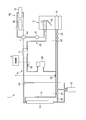
- FIG. 1 is a diagram showing an overall configuration of a vehicle air conditioning system according to the first embodiment.
- a vehicle air conditioning system 1 shown in FIG. 1 is an air conditioning system mounted on a hybrid vehicle including a storage battery and an engine, for example.
- the vehicle air conditioning system 1 includes a refrigerant system P ⁇ b> 1 through which refrigerant circulates, a hot water system P ⁇ b> 2 through which hot water for generating warm air into the vehicle compartment circulates, and cooling water for cooling the engine 18. And an engine cooling water system P3.
- the refrigerant system P1 is provided with a compressor 10, a water / refrigerant heat exchanger 11, a receiver 12, an outdoor heat exchanger 13, an evaporator 14, and expansion valves E1 and E2.
- the compressor 10 sucks and compresses the high-temperature and low-pressure refrigerant obtained through the outdoor heat exchanger 13 or the evaporator 14 and discharges the high-temperature and high-pressure refrigerant.
- the water / refrigerant heat exchanger 11 is one of the heat exchangers in the refrigerant system P1, and is disposed across the refrigerant system P1 and the hot water system P2.
- the water / refrigerant heat exchanger 11 exchanges heat between the refrigerant that goes around the refrigerant system P1 and the hot water that goes around the hot water system P2.
- the receiver 12 performs gas-liquid separation of the refrigerant condensed by the water / refrigerant heat exchanger 11 or the outdoor heat exchanger 13, and sends only the liquid refrigerant to the expansion valve E1 or the expansion valve E2.
- the outdoor heat exchanger 13 is one of heat exchangers in the refrigerant system P1, and is a heat exchanger disposed outside the vehicle.
- the evaporator 14 is one of the heat exchangers in the refrigerant system P1, and is a heat exchanger disposed in the vehicle interior (inside the indoor unit U).
- the expansion valve E1 decompresses the low-temperature and high-pressure refrigerant condensed through the water / refrigerant heat exchanger 11 and sends it to the outdoor heat exchanger 13 during the heating operation.
- the expansion valve E ⁇ b> 2 decompresses the refrigerant condensed through the outdoor heat exchanger 13 and sends it to the evaporator 14 during the defrost operation.
- the refrigerant system P1 further includes two-way solenoid valves V1, V2, a three-way solenoid valve V3, a check valve V5, and refrigerant temperature sensors T1, T2.
- the two-way solenoid valves V1, V2, the three-way solenoid valve V3, and the check valve V5 are solenoid valves that are used to switch between a refrigerant circulation path during heating operation and a refrigerant circulation path during defrost operation.
- the refrigerant temperature sensor T ⁇ b> 1 is a temperature sensor provided in a pipe connecting the refrigerant inlet of the water / refrigerant heat exchanger 11 from the discharge side of the compressor 10.
- the refrigerant temperature sensor T2 is a temperature sensor provided in a pipe connecting the refrigerant outlet of the outdoor heat exchanger 13 and the suction side of the compressor 10.
- strain P1 comprises the heat pump system generally known well. That is, during the heating operation, the refrigerant travels through the refrigerant system P1 in the order of the compressor 10, the water / refrigerant heat exchanger 11, the receiver 12, the expansion valve E1, and the outdoor heat exchanger 13 to the outdoor heat exchanger 13. The absorbed heat is radiated by the water / refrigerant heat exchanger 11.
- the outdoor heat exchanger 13 functions as an evaporator (evaporator), and the water / refrigerant heat exchanger 11 functions as a condenser (condenser).
- the hot water circulating around the hot water system P2 is heated through the water / refrigerant heat exchanger 11.
- the outdoor heat exchanger 13 may be frosted during the heating operation.
- the defrost operation is performed for the purpose of removing (melting) the frost.
- the refrigerant absorbs heat in the evaporator 14 by going through the refrigerant system P1 in the order of the compressor 10, the water / refrigerant heat exchanger 11, the outdoor heat exchanger 13, the receiver 12, the expansion valve E2, and the evaporator 14.
- the generated heat is radiated by the outdoor heat exchanger 13.
- the outdoor heat exchanger 13 functions as a condenser (condenser). Thereby, the outdoor heat exchanger 13 is heated and frost melts.
- the refrigerant circulation path during the normal cooling operation is the same as that during the defrost operation described above. As the refrigerant circulates in the same manner as in the defrost operation, the heat in the vehicle compartment is absorbed through the evaporator 14 and the vehicle compartment is cooled.
- the hot water system P2 is provided with a water pump 17, a heater 15, and a water / refrigerant heat exchanger 11.
- the water pump 17 circulates the hot water in the hot water system P2.
- the hot water circulated by the water pump 17 is heated by absorbing the heat of the refrigerant around the refrigerant system P1 through the water / refrigerant heat exchanger 11.
- the heater 15 functions as a heat source by circulating hot water heated through the water / refrigerant heat exchanger 11.
- the heater 15 is disposed in an indoor unit U that forms a flow path for circulating air in the vehicle compartment.
- the engine cooling water system P3 is provided with an engine 18 to be cooled and a radiator 19.
- the engine 18 is activated when necessary as a power source for the vehicle (for example, when the capacity of the storage battery is reduced in a hybrid vehicle).
- the engine 18 When the engine 18 is driven (rotated), the engine 18 becomes a heat source and the cooling water around the engine cooling water system P3 is heated.
- the radiator 19 exposes the heated cooling water to the outside air to dissipate heat and cool it.
- a four-way valve V4 that can switch connection / disconnection between the pipes is provided between the engine cooling water system P3 and the hot water system P2.
- the indoor unit U is a unit that generates warm air (cold air) according to the heating operation (cooling operation) and sends the warm air (cold air) into the vehicle interior through the vent.
- an evaporator 14, a heater 15, an air mix damper 16 and a blower B are arranged inside the indoor unit U.
- the blower B blows air into the vehicle compartment.
- air (warm air) warmed by the heater 15 is blown into the vehicle compartment by the blower B.
- the air temperature is adjusted according to the opening degree of the air mix damper 16.
- air (cool air) cooled by the evaporator 14 is blown into the vehicle compartment by the blower B.
- the control unit 2 is a control device that controls the operation of the entire vehicle air conditioning system 1. That is, the control unit 2 performs the compressor 10, the water pump 17, the expansion valves E1, E2, and various solenoid valves (two-way solenoid valves V1, V2, three-way solenoid valves V3, four-way valves V4) according to the operation of the vehicle occupant. Then, the air mix damper 16 and the like are controlled to perform the heating operation or the cooling operation. In that case, the control part 2 monitors the refrigerant
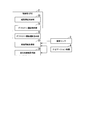
- FIG. 2 is a diagram illustrating a functional configuration of the control unit according to the first embodiment.
- the control unit 2 shown in FIG. 2 is, for example, a CPU (microcomputer) and controls the operation of the entire vehicle air conditioning system 1.
- the control unit 2 operates as a heating operation control unit 20, a defrost operation control unit 21, a defrost operation release instruction unit 22, a vehicle information acquisition unit 23, and a destination information acquisition unit 24 by operating according to a program prepared in advance. Demonstrate.
- the speed sensor 3 is a speed sensor of a vehicle on which the vehicle air conditioning system 1 is mounted, and detects the traveling speed of the vehicle.
- the navigation device 4 is a general car navigation device.
- the navigation device 4 acquires position information (information indicating latitude and longitude) based on radio waves received from a satellite of GNSS (Global Navigation Satellite System), for example.
- the navigation device 4 guides the travel route while presenting the position of the vehicle to the passenger based on the acquired position information.
- position information information indicating latitude and longitude
- GNSS Global Navigation Satellite System
- the heating operation control unit 20 includes the compressor 10 and various valves (expansion valves E1, E2, two-way solenoid valves V1, V2, three-way) provided in the refrigerant system P1.
- the heating operation is performed by controlling the solenoid valve V3 and the like.
- the defrost operation control unit 21 controls the compressor 10 and various valves provided in the refrigerant system P1 to control the defrost when the outflow refrigerant temperature of the outdoor heat exchanger 13 is equal to or lower than the defrost condition threshold during the heating operation. Do the driving.
- the “outflow refrigerant temperature of the outdoor heat exchanger 13” is the temperature of the refrigerant flowing out of the outdoor heat exchanger 13, and specifically, is the temperature detected through the refrigerant temperature sensor T2.
- the defrost operation cancellation instruction unit 22 outputs a defrost operation cancellation instruction to the defrost operation control unit 21 when the outflow refrigerant temperature becomes equal to or higher than the defrost cancellation condition threshold.
- the defrost operation control unit 21 cancels (ends) the defrost operation by receiving the cancel instruction.
- the vehicle information acquisition unit 23 acquires information (vehicle information) indicating the position and speed of the vehicle on which the vehicle air conditioning system 1 is mounted.
- the vehicle information acquisition unit 23 acquires information indicating the speed of the vehicle through the speed sensor 3 mounted on the vehicle. Moreover, the vehicle information acquisition part 23 acquires the information which shows the position of a vehicle through the navigation apparatus 4 mounted in the vehicle.
- the destination information acquisition unit 24 acquires information indicating the destination of the passenger. Specifically, the destination information acquisition unit 24 accesses the navigation device 4 and acquires position (latitude, longitude) information indicating the destination set in the navigation device 4 by the passenger.
- the control unit 2 further controls the compressor 10 and various valves provided in the refrigerant system P1 to perform the cooling operation when the passenger performs a cooling operation request operation. A cooling operation control unit is provided.
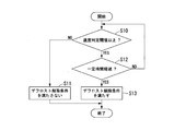
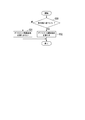
- FIG. 3 is a diagram illustrating a processing flow of the control unit according to the first embodiment.
- FIGS. 4 to 6 are FIGS. 1 to 3 for explaining the processing flow of the control unit according to the first embodiment in detail.
- the processing flow of the control unit 2 according to the first embodiment will be described with reference to FIGS. 3 and 4 to 6.
- the processing flow shown in FIG. 3 is started from the time when the vehicle passenger performs a heating operation request operation.
- the heating operation control unit 20 of the control unit 2 starts the heating operation (step S00).
- the heating operation control unit 20 opens the two-way solenoid valve V1 and closes the two-way solenoid valve V2.
- the heating operation control unit 20 switches the flow path in the three-way solenoid valve V3 to a flow path in which the refrigerant travels from the water / refrigerant heat exchanger 11 to the receiver 12 (see FIG. 1).
- the outdoor heat exchanger 13 functions as an evaporator during heating operation. That is, the refrigerant circulating around the outdoor heat exchanger 13 absorbs heat from the outside air and vaporizes.
- the surface of the outdoor heat exchanger 13 is cooled to below the freezing point due to heat absorption by the refrigerant and frost is formed. If it does so, the refrigerant
- the defrost operation control unit 21 of the control unit 2 determines whether or not the outflow refrigerant temperature of the outdoor heat exchanger 13 has become equal to or lower than the defrost condition threshold Tth1 during the heating operation (step S01).
- the defrost condition threshold value Tth1 is defined as, for example, “outside air temperature ⁇ 5 ° C.” or the like (assuming that the vehicle is additionally provided with a temperature sensor capable of detecting the outside air temperature).
- step S01: NO when the refrigerant temperature flowing out of the outdoor heat exchanger 13 exceeds the defrost condition threshold Tth1 (step S01: NO), the defrost operation control unit 21 does not start the defrost operation, and the heating operation control unit 20 Continue normal heating operation.
- the defrost operation control unit 21 starts the defrost operation (step S02). That is, the defrost operation control unit 21 generates frost in the outdoor heat exchanger 13 when the refrigerant temperature flowing out of the outdoor heat exchanger 13 is equal to or lower than the defrost condition threshold value Tth1 (the refrigerant temperature has not risen sufficiently). Defrost operation is started. The defrost operation control unit 21 closes the two-way solenoid valve V1 and opens the two-way solenoid valve V2 when starting the defrost operation.
- the defrost operation control part 21 switches the flow path in the three-way solenoid valve V3 to the flow path from which the refrigerant goes from the water / refrigerant heat exchanger 11 to the outdoor heat exchanger 13 (see FIG. 1).
- coolant high-temperature / high pressure refrigerant
- the evaporator 14 absorbs heat in the vehicle compartment. Therefore, the room temperature of the vehicle decreases (similar to cooling operation).
- the defrost operation cancellation instruction unit 22 determines whether or not the refrigerant temperature flowing out of the outdoor heat exchanger 13 is equal to or higher than the defrost cancellation condition threshold Tth2 during the defrost operation (step S03).
- the defrost release condition threshold value Tth2 is higher than the defrost condition threshold value Tth1, and is defined as, for example, “10 ° C.” or “15 ° C.”.
- the defrost operation release instruction unit 22 issues a defrost operation release instruction to the defrost operation control unit 21.
- step S05 the defrost operation by the defrost operation control part 21 is cancelled
- the defrost operation release instruction unit 22 determines the defrost release condition based on the position and speed of the vehicle. It is determined whether or not the condition is satisfied (step S04). If the defrost cancellation condition based on the vehicle position and speed is not satisfied (step S04: NO), the defrost operation cancellation instruction unit 22 returns to step S03 without outputting the defrost operation cancellation instruction, and again reaches the outflow refrigerant temperature. Based on the determination process.
- step S04 when the defrost cancellation condition based on the position and speed of the vehicle is satisfied (step S04: YES), the defrost operation cancellation instruction unit 22 outputs a defrost operation cancellation instruction to the defrost operation control unit 21. Thereby, the defrost operation by the defrost operation control part 21 is cancelled
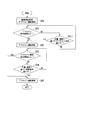
- the defrost operation cancellation instruction unit 22 specifically performs any one or a combination of two or more of the following three processes.
- step S04 the defrost operation cancellation instruction unit 22 executes the determination process shown in FIG. That is, the defrost driving cancellation instructing unit 22 acquires the traveling speed of the vehicle through the vehicle information acquiring unit 23 (FIG. 2), and whether the traveling speed is equal to or higher than a predetermined speed determination threshold Vth (for example, “80 km / h”). It is determined whether or not (step S10).
- a predetermined speed determination threshold Vth for example, “80 km / h”. It is determined whether or not (step S10).
- step S10 NO
- the defrost operation cancellation instruction unit 22 determines that the defrost cancellation condition is not satisfied (defrost operation should be continued), and issues a cancellation instruction.
- step S11 Do not output (step S11). That is, when the traveling speed of the vehicle is relatively slow (less than the speed determination threshold value Vth), it is considered that the degree of degradation of the defrost performance due to traveling wind is small. Therefore, the frost attached to the outdoor heat exchanger 13 can be effectively removed by performing the defrost operation.
- step S10 the traveling speed of the vehicle is equal to or higher than the speed determination threshold Vth (step S10: YES)
- the defrosting operation cancellation instructing unit 22 then performs a predetermined time while the traveling speed of the vehicle remains equal to or higher than the speed determination threshold Vth. It is determined whether or not (for example, “5 minutes”, etc., hereinafter also referred to as “fixed time”) has elapsed (step S12).
- step S12 determines whether the traveling speed of the vehicle is equal to or greater than the speed determination threshold Vth. (Step S10) is repeated. On the other hand, when a certain period of time has passed with the vehicle traveling speed equal to or higher than the speed determination threshold Vth (step S12: YES), the defrost operation cancellation instruction unit 22 determines that the defrost cancellation condition is satisfied (defrost operation should be canceled). Then, a release instruction is output (step S13).
- the vehicle travel speed is relatively high (the speed determination threshold value Vth or more) continues for a certain time or longer, the vehicle is in a driving situation in which the travel speed does not decrease for a while (highway, main road And so on). Therefore, even if the defrost operation is performed, the effect is not sufficiently obtained, and it is assumed that a long time is required until the defrost release condition is satisfied (the outflow refrigerant temperature becomes equal to or higher than the defrost release condition threshold value Tth2).
- the defrosting operation cancellation instructing unit 22 performs the defrosting operation even if the outflow refrigerant temperature of the outdoor heat exchanger 13 has not risen to the defrosting cancellation condition threshold value Tth2.
- a release instruction is output for release.
- the refrigerant temperature flowing out of the outdoor heat exchanger 13 is raised to some extent by the defrost operation before the release instruction is output (although it has not reached the defrost release condition threshold value Tth2). Therefore, the vehicle air conditioning system 1 can perform the heating operation even after the defrost operation is canceled through step S13.
- step S04 Defrost operation cancellation condition determination process based on road on which vehicle travels
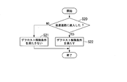
- the defrost operation cancellation instruction unit 22 executes the determination process shown in FIG. That is, the defrost driving cancellation instruction unit 22 acquires the travel position of the vehicle through the vehicle information acquisition unit 23 (FIG. 2), compares the travel position with the map information, and the vehicle enters the pre-designated expressway. Is determined (step S20). If the vehicle has not entered the designated highway (step S20: NO), the defrost operation cancellation instruction unit 22 determines that the defrost cancellation condition is not satisfied (defrost operation should be continued), and issues a cancellation instruction. No output is made (step S21).
- step S20 when the vehicle is not traveling on the highway, it is considered that the degree of degradation of the defrost performance due to traveling wind is small. Therefore, the frost attached to the outdoor heat exchanger 13 can be effectively removed by performing the defrost operation.
- the defrost operation cancellation instruction unit 22 determines that the defrost cancellation condition is satisfied (defrost operation should be canceled) and outputs a cancellation instruction. (Step S22). That is, when the vehicle enters the highway, it is assumed that the vehicle continues to travel at a high speed for a while.
- the defrosting operation cancellation instructing unit 22 performs the defrosting operation even if the outflow refrigerant temperature of the outdoor heat exchanger 13 has not increased to the defrosting cancellation condition threshold value Tth2.
- a release instruction is output for release.
- step S04 the defrost operation cancellation instruction unit 22 executes the determination process shown in FIG. That is, the defrost driving cancellation instruction unit 22 first acquires position information indicating the passenger's destination through the destination information acquisition unit 24 (FIG. 2). Next, the defrost driving cancellation
- the defrost operation cancellation instruction unit 22 satisfies the defrost cancellation condition (the defrost operation should be canceled) when the distance from the destination to the current position of the vehicle is equal to or less than a predetermined determination threshold (for example, “5 km”). ) And output a release instruction. That is, when the vehicle approaches the destination, it is assumed that the time from arrival to the destination is short. Even if the defrost operation is continued in such a situation, the vehicle is highly likely to stop before the heating operation is resumed. That is, in order to ensure high heating performance after a predetermined time has elapsed (after defrost operation is canceled), it is extremely small to continue the defrost operation at the present time.
- a predetermined determination threshold for example, “5 km”.
- the defrost operation cancellation instruction unit 22 in order to prevent the defrost operation cancellation instruction unit 22 from reaching the destination without resuming the heating operation, even if the outflow refrigerant temperature of the outdoor heat exchanger 13 does not rise to the defrost cancellation condition threshold value Tth2, the defrost operation cancellation instruction unit 22 A cancel instruction is output to cancel the operation.
- step S01 to step S05 shown in FIG. 3 The processing flow from step S01 to step S05 shown in FIG. 3 is repeatedly executed even after the defrost operation is canceled by the defrost operation cancel instruction unit 22 and the heating operation by the heating operation control unit 20 is restarted.
- the control unit 2 of the vehicle air-conditioning system 1 performs the refrigerant system P1 when the outflow refrigerant temperature of the outdoor heat exchanger 13 in the refrigerant system P1 is equal to or lower than the defrost condition threshold value Tth1.
- the defrosting operation control unit 21 that performs the defrosting operation, the defrosting operation cancellation instructing unit 22 that outputs a defrosting operation cancellation instruction when the outflow refrigerant temperature becomes equal to or higher than the defrosting cancellation condition threshold value Tth2, and the vehicle air conditioning system 1
- a vehicle information acquisition unit 23 that acquires at least one of the position and speed of the vehicle to be mounted.
- the defrost operation cancellation instructing unit 22 further performs the defrost operation even when the outflow refrigerant temperature is less than the defrost cancellation condition threshold value Tth2 when at least one of the position and speed of the vehicle satisfies a predetermined condition. Output a release instruction. By doing in this way, it can control that defrost operation continues for a long time in the environment where defrost performance cannot fully be acquired, and the time when heating operation cannot be used increases.
- FIG. 7 is a diagram illustrating a processing flow of the control unit according to the second embodiment. Note that the overall configuration and functional configuration of the vehicle air conditioning system 1 according to the second embodiment are the same as those in the first embodiment (FIGS. 1 and 2), and hence illustration is omitted.
- FIG. 7 for example, the processing flow illustrated in FIG. 7 is started when the defrost operation is canceled and the heating operation by the heating operation control unit 20 is resumed.
- step S02 when the refrigerant temperature flowing out of the outdoor heat exchanger 13 becomes equal to or lower than the defrost condition threshold Tth1 (step S01: YES), the defrost operation control unit 21 starts the defrost operation (step S02).
- the defrost operation control unit 21 further sets the defrost condition based on the position and speed of the vehicle. It is determined whether or not it is satisfied (step S011).
- step S011: NO When the defrost condition based on the position and speed of the vehicle is not satisfied (step S011: NO), the defrost operation control unit 21 returns to step S01 without starting the defrost operation, and again performs the determination process based on the outflow refrigerant temperature. Do.
- step S011: YES when the defrost condition based on the position and speed of the vehicle is satisfied (step S011: YES), the defrost operation control unit 21 starts the defrost operation (step S02). That is, when the defrost condition is satisfied based on the position and speed of the vehicle, the defrost operation control unit 21 starts the defrost operation even if the outflow refrigerant temperature exceeds the defrost condition threshold value Tth1.
- step S011 the defrost operation control unit 21 specifically performs any one or combination of the following processes.
- step S011 when the traveling speed of the vehicle is less than the speed determination threshold value Vth and the refrigerant temperature flowing out of the outdoor heat exchanger 13 is less than the defrost release condition threshold value Tth2, the defrost operation is performed.
- the controller 21 starts the defrost operation even if the outflow refrigerant temperature exceeds the defrost condition threshold value Tth1. That is, when the vehicle traveling speed once becomes low (less than the speed determination threshold Vth), it is assumed that the high-speed traveling operation is terminated, and there are more opportunities for obtaining sufficient defrost performance in the future.
- the defrost operation is canceled before the refrigerant temperature flowing out rises to the defrost cancellation condition threshold value Tth2, the defrost operation is restarted, and the defrost operation is sufficiently performed until the end (until the frost is completely removed). Will be continued.
- step S011 when it is determined in step S011 that the vehicle has left the highway and the temperature of the refrigerant flowing out of the outdoor heat exchanger 13 is less than the defrost release condition threshold value Tth2, the defrost operation control unit No. 21 starts the defrost operation even if the outflow refrigerant temperature exceeds the defrost condition threshold value Tth1. That is, when the vehicle leaves the highway, it is assumed that the traveling speed of the vehicle decreases and the opportunity for obtaining sufficient defrost performance increases. Therefore, when the defrost operation is canceled before the outflow refrigerant temperature rises to the defrost cancellation condition threshold value Tth2, the defrost operation is sufficiently continued until the end by restarting the defrost operation.
- step S03 the processing after step S03 is the same as that of the first embodiment, and thus the description thereof is omitted.
- the control unit 2 defrost operation cancellation instructing unit 22
- indication part 22 may be made into the aspect which outputs a cancellation
- control part 2 which concerns on 2nd Embodiment presupposes that the defrost driving
- the determination process in step S011 is performed.
- control part 2 which concerns on other embodiment may be the aspect which does not comprise the defrost driving
- control unit 2 according to the other implementation / BR> ⁇ state“ the outflow refrigerant temperature exceeds the defrost condition threshold Tth1 when at least one of the position and speed of the vehicle satisfies a predetermined condition.
- An embodiment having only the function of “performing defrost operation even if it is present” may be used.
- the various processes of the above-described vehicle air conditioning system 1 are stored in a computer-readable recording medium in the form of a program.
- the various processes described above are performed by reading and executing.
- the computer-readable recording medium is a magnetic disk, a magneto-optical disk, a CD-ROM, a DVD-ROM, a semiconductor memory, or the like.
- the computer program may be distributed to the computer via a communication line, and the computer that has received the distribution may execute the program.
- the above program may be for realizing a part of the above-described functions. Furthermore, what can implement
- the vehicle air conditioning system According to the control device, the vehicle air conditioning system, the vehicle air conditioning system control method, and the program described above, it is possible to prevent the defrost operation from continuing for a long time.
Landscapes
- Engineering & Computer Science (AREA)
- Mechanical Engineering (AREA)
- Physics & Mathematics (AREA)
- Thermal Sciences (AREA)
- General Engineering & Computer Science (AREA)
- Chemical & Material Sciences (AREA)
- Combustion & Propulsion (AREA)
- Transportation (AREA)
- Air-Conditioning For Vehicles (AREA)
Priority Applications (3)
| Application Number | Priority Date | Filing Date | Title |
|---|---|---|---|
| CN201880031078.6A CN110621524A (zh) | 2017-05-15 | 2018-04-16 | 控制装置、车辆用空调系统、车辆用空调系统控制方法及程序 |
| DE112018002488.1T DE112018002488T5 (de) | 2017-05-15 | 2018-04-16 | Steuerungsvorrichtung, fahrzeugklimaanlage, verfahren zum steuern einer fahrzeugklimaanlage, und programm |
| US16/609,368 US20200055370A1 (en) | 2017-05-15 | 2018-04-16 | Control device, vehicular air conditioning system, method for controlling vehicular air conditioning system, and program |
Applications Claiming Priority (2)
| Application Number | Priority Date | Filing Date | Title |
|---|---|---|---|
| JP2017096638A JP2018192860A (ja) | 2017-05-15 | 2017-05-15 | 制御装置、車両用空調システム、車両用空調システム制御方法及びプログラム |
| JP2017-096638 | 2017-05-15 |
Publications (1)
| Publication Number | Publication Date |
|---|---|
| WO2018211888A1 true WO2018211888A1 (ja) | 2018-11-22 |
Family
ID=64273606
Family Applications (1)
| Application Number | Title | Priority Date | Filing Date |
|---|---|---|---|
| PCT/JP2018/015773 WO2018211888A1 (ja) | 2017-05-15 | 2018-04-16 | 制御装置、車両用空調システム、車両用空調システム制御方法及びプログラム |
Country Status (5)
Families Citing this family (11)
| Publication number | Priority date | Publication date | Assignee | Title |
|---|---|---|---|---|
| EP3666565B1 (en) * | 2017-08-08 | 2022-08-10 | Hangzhou Sanhua Research Institute Co., Ltd. | Automotive air conditioning system |
| CN110470004B (zh) * | 2019-08-02 | 2022-09-02 | 青岛海尔空调器有限总公司 | 用于空调除霜的控制方法及装置、空调 |
| JP7396116B2 (ja) * | 2020-02-27 | 2023-12-12 | 株式会社デンソー | 車両用空調装置 |
| DE102020207170A1 (de) * | 2020-06-09 | 2021-12-09 | Volkswagen Aktiengesellschaft | Verfahren zum Enteisen eines Wärmeübertragers eines Kraftfahrzeugs und Kraftfahrzeug mit einem Wärmeübertrager |
| CN114571958B (zh) * | 2020-11-30 | 2024-07-23 | 长城汽车股份有限公司 | 车辆除霜雾控制方法、介质及控制器 |
| CN112389159A (zh) * | 2020-12-01 | 2021-02-23 | 安徽江淮汽车集团股份有限公司 | 车辆空调系统控制方法、车辆及存储介质 |
| CN112874259A (zh) * | 2021-01-21 | 2021-06-01 | 智马达汽车有限公司 | 一种具有除冰装置的汽车热泵系统及汽车 |
| DE102021201380A1 (de) * | 2021-02-15 | 2022-08-18 | Volkswagen Aktiengesellschaft | Verfahren zum Einleiten eines Abtauprozesses eines Wärmeübertragers einer Wärmepumpe eines Kraftfahrzeugs |
| CN115610372A (zh) * | 2021-07-16 | 2023-01-17 | 上海博泰悦臻网络技术服务有限公司 | 使用清洁剂清洁车辆玻璃的方法、系统、介质及终端 |
| US12055316B2 (en) * | 2021-09-17 | 2024-08-06 | Addison Hvac Llc | Air-conditioning system with variable subcooling |
| FR3149078A1 (fr) * | 2023-05-25 | 2024-11-29 | Valeo Systemes Thermiques | Procédé de contrôle d’un système de conditionnement thermique pour véhicule électrique |
Citations (4)
| Publication number | Priority date | Publication date | Assignee | Title |
|---|---|---|---|---|
| JPH0755297A (ja) * | 1993-08-09 | 1995-03-03 | Mitsubishi Heavy Ind Ltd | 車両用ヒートポンプ式空調装置 |
| JP2001010334A (ja) * | 1999-06-07 | 2001-01-16 | Mitsubishi Heavy Ind Ltd | ヒートポンプ式車両用空調装置 |
| JP2012176660A (ja) * | 2011-02-25 | 2012-09-13 | Sanden Corp | 車両用空気調和装置 |
| JP2016049914A (ja) * | 2014-09-01 | 2016-04-11 | 本田技研工業株式会社 | 電動車両の車両用空調装置 |
Family Cites Families (2)
| Publication number | Priority date | Publication date | Assignee | Title |
|---|---|---|---|---|
| KR101241222B1 (ko) * | 2011-07-21 | 2013-03-13 | 기아자동차주식회사 | 차량용 히트펌프 시스템 제어방법 |
| CN103328238B (zh) * | 2011-01-21 | 2015-11-25 | 三电有限公司 | 车辆用空气调节装置 |
-
2017
- 2017-05-15 JP JP2017096638A patent/JP2018192860A/ja active Pending
-
2018
- 2018-04-16 WO PCT/JP2018/015773 patent/WO2018211888A1/ja active Application Filing
- 2018-04-16 US US16/609,368 patent/US20200055370A1/en not_active Abandoned
- 2018-04-16 CN CN201880031078.6A patent/CN110621524A/zh active Pending
- 2018-04-16 DE DE112018002488.1T patent/DE112018002488T5/de not_active Withdrawn
Patent Citations (4)
| Publication number | Priority date | Publication date | Assignee | Title |
|---|---|---|---|---|
| JPH0755297A (ja) * | 1993-08-09 | 1995-03-03 | Mitsubishi Heavy Ind Ltd | 車両用ヒートポンプ式空調装置 |
| JP2001010334A (ja) * | 1999-06-07 | 2001-01-16 | Mitsubishi Heavy Ind Ltd | ヒートポンプ式車両用空調装置 |
| JP2012176660A (ja) * | 2011-02-25 | 2012-09-13 | Sanden Corp | 車両用空気調和装置 |
| JP2016049914A (ja) * | 2014-09-01 | 2016-04-11 | 本田技研工業株式会社 | 電動車両の車両用空調装置 |
Also Published As
| Publication number | Publication date |
|---|---|
| JP2018192860A (ja) | 2018-12-06 |
| CN110621524A (zh) | 2019-12-27 |
| US20200055370A1 (en) | 2020-02-20 |
| DE112018002488T5 (de) | 2020-02-13 |
Similar Documents
| Publication | Publication Date | Title |
|---|---|---|
| WO2018211888A1 (ja) | 制御装置、車両用空調システム、車両用空調システム制御方法及びプログラム | |
| JP7221639B2 (ja) | 車両用空気調和装置 | |
| JP6593375B2 (ja) | 車両用熱管理装置 | |
| JP7263116B2 (ja) | 車両搭載機器の温度調整装置及びそれを備えた車両用空気調和装置 | |
| JP5611072B2 (ja) | ヒートポンプ式車両用空調装置およびその除霜方法 | |
| US20050022983A1 (en) | Heat pump with secondary loop air-conditioning system | |
| JP7300264B2 (ja) | 車両用空気調和装置 | |
| US20160075212A1 (en) | Heat-pump-type vehicle air conditioning system and defrosting method thereof | |
| CN112424006B (zh) | 车辆用空调装置 | |
| JP2006519133A (ja) | 空気と熱伝導流体とを同時に冷却する、自動車の乗員コンパートメンとのための換気、暖房、または空調装置 | |
| JP6997567B2 (ja) | 車両用空気調和装置 | |
| JP2018128243A (ja) | 除霜機能をもつヒートポンプ装置 | |
| JP2017065653A (ja) | 車両用熱利用装置 | |
| US12023994B2 (en) | Motor vehicle air-conditioning circuit and related management method | |
| WO2021177057A1 (ja) | 車両用空気調和装置 | |
| JP2012162149A (ja) | ヒートポンプ式車両用空調装置 | |
| JP2014225981A (ja) | 車両の制御装置、熱管理システム、プログラム、及び車両の制御方法 | |
| US20240399819A1 (en) | Vehicle thermal management system | |
| WO2020129493A1 (ja) | 車両用空気調和装置 | |
| CN116075439A (zh) | 车辆用空调装置 | |
| WO2014185150A1 (ja) | 車両用空調装置、車両用空調装置の制御方法、及びプログラム | |
| JP2005041252A (ja) | 車両用空調装置 | |
| JP5984479B2 (ja) | 車両用空調装置 | |
| JP7080014B2 (ja) | 車両用空調システム | |
| JP7559692B2 (ja) | 車両用熱マネジメントシステム |
Legal Events
| Date | Code | Title | Description |
|---|---|---|---|
| 121 | Ep: the epo has been informed by wipo that ep was designated in this application |
Ref document number: 18802222 Country of ref document: EP Kind code of ref document: A1 |
|
| 122 | Ep: pct application non-entry in european phase |
Ref document number: 18802222 Country of ref document: EP Kind code of ref document: A1 |