WO2018207832A1 - ダイナモメータシステムの制御装置 - Google Patents
ダイナモメータシステムの制御装置 Download PDFInfo
- Publication number
- WO2018207832A1 WO2018207832A1 PCT/JP2018/017967 JP2018017967W WO2018207832A1 WO 2018207832 A1 WO2018207832 A1 WO 2018207832A1 JP 2018017967 W JP2018017967 W JP 2018017967W WO 2018207832 A1 WO2018207832 A1 WO 2018207832A1
- Authority
- WO
- WIPO (PCT)
- Prior art keywords
- signal
- torque
- dynamometer
- calculation unit
- loss
- Prior art date
- Legal status (The legal status is an assumption and is not a legal conclusion. Google has not performed a legal analysis and makes no representation as to the accuracy of the status listed.)
- Ceased
Links
Images



Classifications
-
- G—PHYSICS
- G01—MEASURING; TESTING
- G01M—TESTING STATIC OR DYNAMIC BALANCE OF MACHINES OR STRUCTURES; TESTING OF STRUCTURES OR APPARATUS, NOT OTHERWISE PROVIDED FOR
- G01M17/00—Testing of vehicles
- G01M17/007—Wheeled or endless-tracked vehicles
- G01M17/0072—Wheeled or endless-tracked vehicles the wheels of the vehicle co-operating with rotatable rolls
- G01M17/0074—Details, e.g. roller construction, vehicle restraining devices
-
- G—PHYSICS
- G01—MEASURING; TESTING
- G01L—MEASURING FORCE, STRESS, TORQUE, WORK, MECHANICAL POWER, MECHANICAL EFFICIENCY, OR FLUID PRESSURE
- G01L3/00—Measuring torque, work, mechanical power, or mechanical efficiency, in general
- G01L3/16—Rotary-absorption dynamometers, e.g. of brake type
- G01L3/22—Rotary-absorption dynamometers, e.g. of brake type electrically or magnetically actuated
-
- G—PHYSICS
- G01—MEASURING; TESTING
- G01M—TESTING STATIC OR DYNAMIC BALANCE OF MACHINES OR STRUCTURES; TESTING OF STRUCTURES OR APPARATUS, NOT OTHERWISE PROVIDED FOR
- G01M13/00—Testing of machine parts
- G01M13/02—Gearings; Transmission mechanisms
-
- G—PHYSICS
- G01—MEASURING; TESTING
- G01M—TESTING STATIC OR DYNAMIC BALANCE OF MACHINES OR STRUCTURES; TESTING OF STRUCTURES OR APPARATUS, NOT OTHERWISE PROVIDED FOR
- G01M13/00—Testing of machine parts
- G01M13/02—Gearings; Transmission mechanisms
- G01M13/027—Test-benches with force-applying means, e.g. loading of drive shafts along several directions
-
- G—PHYSICS
- G01—MEASURING; TESTING
- G01M—TESTING STATIC OR DYNAMIC BALANCE OF MACHINES OR STRUCTURES; TESTING OF STRUCTURES OR APPARATUS, NOT OTHERWISE PROVIDED FOR
- G01M13/00—Testing of machine parts
- G01M13/02—Gearings; Transmission mechanisms
- G01M13/028—Acoustic or vibration analysis
-
- G—PHYSICS
- G05—CONTROLLING; REGULATING
- G05B—CONTROL OR REGULATING SYSTEMS IN GENERAL; FUNCTIONAL ELEMENTS OF SUCH SYSTEMS; MONITORING OR TESTING ARRANGEMENTS FOR SUCH SYSTEMS OR ELEMENTS
- G05B13/00—Adaptive control systems, i.e. systems automatically adjusting themselves to have a performance which is optimum according to some preassigned criterion
- G05B13/02—Adaptive control systems, i.e. systems automatically adjusting themselves to have a performance which is optimum according to some preassigned criterion electric
- G05B13/04—Adaptive control systems, i.e. systems automatically adjusting themselves to have a performance which is optimum according to some preassigned criterion electric involving the use of models or simulators
-
- G—PHYSICS
- G05—CONTROLLING; REGULATING
- G05B—CONTROL OR REGULATING SYSTEMS IN GENERAL; FUNCTIONAL ELEMENTS OF SUCH SYSTEMS; MONITORING OR TESTING ARRANGEMENTS FOR SUCH SYSTEMS OR ELEMENTS
- G05B13/00—Adaptive control systems, i.e. systems automatically adjusting themselves to have a performance which is optimum according to some preassigned criterion
- G05B13/02—Adaptive control systems, i.e. systems automatically adjusting themselves to have a performance which is optimum according to some preassigned criterion electric
- G05B13/04—Adaptive control systems, i.e. systems automatically adjusting themselves to have a performance which is optimum according to some preassigned criterion electric involving the use of models or simulators
- G05B13/042—Adaptive control systems, i.e. systems automatically adjusting themselves to have a performance which is optimum according to some preassigned criterion electric involving the use of models or simulators in which a parameter or coefficient is automatically adjusted to optimise the performance
Definitions
- the present invention relates to a control device for a dynamometer system.
- a load cell is used as a sensor for detecting torque related to the control and measurement.
- the load cell detects the torque acting on the dynamometer rocker through a torque arm extending from the rocker. Due to such a structure, the output signal of the load cell is not the torque actually detected by the dynamometer, but the torque fluctuation component accompanying the natural vibration of the oscillator is superimposed. It is a component that is essentially unnecessary in the control and measurement.
- Patent Documents 1 and 2 In the control device of the dynamometer system described in Patent Literatures 1 and 2, the correction signal that suppresses the natural vibration of the oscillator is generated by the natural vibration suppression control circuit, and the upper torque generated by the upper control device. By inputting the command signal corrected by this correction signal to the dynamometer, the vibration of the oscillator itself is suppressed, and a detection signal of the load cell with a small fluctuation component is obtained.
- These natural vibration suppression control circuits described in Patent Documents 1 and 2 generate a correction signal that suppresses the natural vibration of the oscillator by using a reference model that imitates the input / output characteristics of the dynamometer system.
- a roller on which a driving wheel of a vehicle that is a specimen is installed and ancillary equipment such as a plurality of flywheels for realizing set inertia correspond to this load.
- ancillary equipment such as a plurality of flywheels for realizing set inertia
- additional equipment such as an intermediate shaft and a speed increaser provided between the input shaft of the drive train that is the specimen and the output shaft of the dynamometer falls under this load. If so, an auxiliary device such as an intermediate shaft provided between the output shaft of the engine as the specimen and the output shaft of the dynamometer corresponds to this load.
- An object of the present invention is to provide a control device for a dynamometer system capable of stable control with high response even when the configuration of a load connected to a dynamometer body is changed and capable of measuring with high accuracy. .
- a dynamometer system (for example, a dynamometer system 1 described later) includes a oscillating dynamometer body (for example, a dynamometer body 2 described later) and a load connected to an output shaft of the dynamometer body ( For example, rollers 6L and 6R and flywheels 71, 72, and 73 described later, an inverter that supplies power to the dynamometer body according to a torque current command signal (for example, an inverter 3 described later), and the dynamometer body Torque sensor (for example, a load cell, which will be described later) that detects torque generated in the oscillator (for example, a later-described oscillator 21) via a torque arm (for example, torque arm 26, which will be described later) extending from the oscillator.
- a torque current command signal for example, an inverter 3 described later
- Torque sensor for example, a load cell, which will be described later
- a torque arm for example, torque arm 26, which will be described later
- a control device for example, a control device 4 described later
- the load is connected based on a detection signal (for example, an angular velocity detection signal SPdy_det described later) of the angular velocity sensor.
- a loss calculation unit for example, a mechanical loss calculation unit 48 described later
- a loss compensation signal for example, a loss compensation signal ML_ref described later
- the detection signal for example, load cell torque detection signal LC_det described later
- the loss compensation signal By using the detection signal (for example, load cell torque detection signal LC_det described later) and the loss compensation signal, a natural vibration suppression that generates a correction signal for the upper torque command signal so as to suppress the natural vibration of the oscillator is suppressed.
- a control circuit for example, a natural vibration suppression control circuit 43 to be described later and the upper torque command signal
- a torque current command signal generation unit (for example, a torque current command signal generation unit 49 to be described later) that inputs the torque current command signal generated by subtracting the correction signal to the inverter.
- the control circuit includes a reference model calculation unit (for example, a reference model calculation unit 432 described later) having input / output characteristics simulating characteristics from the torque current command signal to the detection signal of the torque sensor in the dynamometer system, A deviation compensator (for example, described later) that generates a feedback signal that reduces the deviation by using a deviation (for example, later-described deviation err) between the output torque signal from the reference model calculation unit and the detection signal of the torque sensor.
- Deviation compensator 433 and torque obtained by subtracting the loss compensation signal from the torque current command signal
- a model input generation unit for example, a model input generation unit 434 described later
- a torque signal for example, a differential compensator (for example, a differential compensator 437 described later) that generates the correction signal by performing a differential operation on a torque signal Pmdl_det described later is provided.
- the loss calculation unit includes a storage medium that stores a lookup table that defines a correspondence relationship between the value of the detection signal of the angular velocity sensor and the value of the loss compensation signal according to the value. It is preferable to generate the loss compensation signal having a value obtained by searching the lookup table using the value of the detection signal of the angular velocity sensor.
- the load includes one or more auxiliary devices connected to the output shaft
- the storage medium includes a combination of the dynamometer main body and the auxiliary devices connected to the dynamometer main body.
- a plurality of different look-up tables are stored for each, and the loss calculation unit selects one of the plurality of look-up tables according to an operation of an operator and uses a value of a detection signal of the angular velocity sensor.
- the loss compensation signal having a value obtained by searching the selected lookup table is generated.
- the loss calculation unit includes a storage medium that stores a calculation expression that receives the value of the detection signal of the angular velocity sensor and outputs the value of the loss compensation signal according to the input, and the angular velocity It is preferable to generate the loss compensation signal having a value obtained by inputting the value of the detection signal of the sensor into the arithmetic expression.
- the load includes one or more auxiliary devices connected to the output shaft
- the storage medium includes a combination of the dynamometer body and the auxiliary devices connected to the dynamometer body.
- a plurality of different arithmetic expressions are stored for each, and the loss calculator selects one of the plurality of arithmetic expressions according to an operation of an operator and selects the value of the detection signal of the angular velocity sensor It is preferable to generate the loss compensation signal having a value obtained by inputting the calculation expression.
- a torque current command signal is generated by subtracting the correction signal generated by the natural vibration suppression control circuit from the upper torque command signal, and this is generated to the inverter of the dynamometer body to which the load is connected. input.
- the transfer function from the input to the inverter to the output of the torque sensor is approximately expressed by a second order lag standard form. Therefore, in the natural vibration suppression control circuit of the present invention, differential compensation is applied to the torque signal obtained by the reference model calculation unit having input / output characteristics simulating the characteristics from the torque current command signal to the detection signal of the torque sensor in the dynamometer system.
- a correction signal is generated by performing a differentiation operation with a generator, and a torque current command signal is generated by subtracting the correction signal from the higher-order torque command signal.
- the dynamometer body can be damped so as to suppress the natural vibration of the oscillator.
- the control device of the present invention by providing a natural vibration suppression control circuit including such a differential compensator, the natural vibration of the oscillator itself is suppressed, and thus unnecessary torque fluctuation components are detected from the detection signal of the torque sensor. Can be removed. Therefore, according to the present invention, a stable detection signal can be obtained from the torque sensor without using a filtering technique with a low cutoff (cutoff) frequency. Further, by suppressing the natural vibration of the oscillator using such a natural vibration suppression control circuit, stable control with high response can be realized.
- the loss calculation unit of the present invention generates a loss compensation signal corresponding to the loss torque generated in the dynamometer body with the load connected based on the detection signal of the angular velocity sensor, and the natural vibration suppression control circuit
- the correction signal is generated by using the torque current command signal, the detection signal of the torque sensor, and the loss compensation signal. More specifically, the natural vibration suppression control circuit uses the torque signal obtained by subtracting the loss compensation signal from the torque current command signal and the feedback signal calculated by the deviation compensator, and the reference model calculation unit.
- the loss calculation unit of the present invention generates a loss compensation signal by searching a predetermined lookup table using the value of the detection signal of the angular velocity sensor. Thereby, the loss compensation signal according to the detection signal of the angular velocity sensor can be quickly generated.
- the magnitude of mechanical loss generated in the dynamometer main body also changes. Therefore, in the present invention, a plurality of different lookup tables are stored in the storage medium for each combination of the dynamometer body and ancillary equipment connected to the dynamometer body, and a plurality of lookup tables are stored according to the operation of the operator.
- the loss compensation signal is generated by selecting one of the tables and searching the selected lookup table using the value of the detection signal of the angular velocity sensor.
- the loss calculation unit of the present invention generates a loss compensation signal by inputting the value of the detection signal of the angular velocity sensor into a predetermined calculation formula. Thereby, the loss compensation signal according to the detection signal of the angular velocity sensor can be quickly generated.
- a plurality of different arithmetic expressions are stored in the storage medium for each combination of the dynamometer main body and the accessory device connected as a load to the output shaft of the dynamometer main body.
- one of a plurality of arithmetic expressions is selected, and the loss compensation signal is generated by inputting the value of the detection signal of the angular velocity sensor into the selected arithmetic expression.
- FIG. 1 is a diagram illustrating a configuration of a dynamometer system 1 according to the present embodiment.
- the dynamometer system 1 includes an oscillating dynamometer body 2, rollers 6L and 6R and a plurality of flywheels 71, 72, and 73 provided as loads on the output shaft 22 of the dynamometer body 2, and these rollers 6L.
- the left and right wheels of a vehicle (not shown) to be tested are placed on the rollers 6L and 6R, respectively.
- the flywheels 71 to 73 have different masses and are detachably attached to the output shaft 22.
- the flywheels 71 to 73 are appropriately combined and provided on the output shaft 22, so that the equivalent inertia corresponding to the weight of the test vehicle is achieved. Set the mass.
- FIG. 2 is a diagram of the dynamometer body 2 viewed along the axial direction.
- the dynamometer body 2 includes a cylindrical oscillator 21, an output shaft 22 rotatably supported in the oscillator 21, and a base 24 on which the oscillator 21 is fixed to the installation surface G.
- a pedestal 25 that is supported so as to be able to swing along the circumferential direction, a load cell 28 that detects torque generated in the oscillator 23, and an encoder 29 that detects the rotational speed of the rotor 22 are provided.
- a torque arm 26 extending outward in the radial direction is provided on the side of the oscillator 21.
- the load cell 28 is provided between the tip end portion of the torque arm 26 and the installation surface G.
- the load cell 28 transmits a detection signal (hereinafter also referred to as “load cell torque detection signal”) corresponding to a load (output torque of the dynamometer body 2) acting between the torque arm 26 and the installation surface G to the control device 4. To do.
- an acceleration sensor 30 for detecting the acceleration of the torque arm 26 is provided at the tip of the torque arm 26.
- the acceleration sensor 30 transmits a detection signal corresponding to the acceleration of the torque arm 26 along the load direction of the load cell 28 to the control device 4.
- the encoder 29 transmits a pulse signal corresponding to the angular velocity of the output shaft 22 (hereinafter also referred to as “angular velocity detection signal”) to the control device 4.
- the control device 4 generates a torque current command signal for the dynamometer body 2 based on detection signals of the load cell 28, the encoder 29, and the acceleration sensor 30, and inputs them to the inverter 3.
- the inverter 3 supplies electric power corresponding to the torque current command signal to the dynamometer body 2.
- FIG. 3 is a block diagram showing the configuration of the control device 4.
- the control object P includes the inverter, the dynamometer body, the load cell, the acceleration sensor, and the like described with reference to FIGS. 1 and 2.
- the control device 4 includes an upper control unit 41 that generates an upper torque command signal for the torque current command signal, and a natural vibration suppression control circuit that generates a correction signal for correcting the upper torque command signal output from the upper control unit 41. 43, a correction circuit 47 for correcting the load cell torque detection signal of the load cell, a mechanical loss calculation unit 48 for generating a loss compensation signal corresponding to the mechanical loss torque generated in the dynamometer body based on the angular velocity detection signal of the encoder, A torque current command signal generation unit 49.
- the upper control unit 41 uses a control command determined by a process (not shown), a load cell torque detection signal from which torque pulsation and noise are removed through a correction circuit 47 described later, and an angle detection signal. An upper torque command signal is generated.
- the torque current command signal generation unit 49 generates a torque current command signal by subtracting a correction signal generated by a natural vibration suppression control circuit 43 described later from the upper torque command signal generated by the upper control unit 41, This is input to the inverter.
- the correction circuit 47 includes a torque converter 471, an adder 473, and a low-pass filter 475.
- the torque conversion unit 471 generates a torque signal by removing a direct current component having a frequency equal to or lower than a predetermined frequency from the detection signal of the acceleration sensor, inverting the phase by 180 degrees, and further multiplying by a predetermined coefficient.
- the adder 473 removes torque pulsation components from the load cell torque detection signal by adding the torque signal generated by the torque converter 471 to the load cell torque detection signal.
- the low pass filter 475 removes harmonic noise from the torque signal generated by the adder 473, thereby inputting the load cell torque detection signal from which torque pulsation, noise, and the like have been removed, to the upper controller 41.
- the mechanical loss calculation unit 48 estimates the mechanical loss torque generated in the dynamometer main body in a state where the rollers and flywheels that are incidental devices in the dynamometer system 1 are connected, and this is lost. Output as a compensation signal.
- FIG. 4 is a diagram illustrating an example of a calculation result in the mechanical loss calculation unit 48.
- the horizontal axis represents the angular velocity [rad / s] corresponding to the input of the mechanical loss calculation unit 48
- the vertical axis represents the mechanical loss torque [Nm] corresponding to the output of the mechanical loss calculation unit 48.
- the mechanical loss calculator 48 increases the mechanical loss torque as the angular velocity value increases.
- the natural vibration suppression control circuit 43 is based on a torque current command signal to the inverter, a load cell torque detection signal that has not passed through the correction circuit 47 described later, and a loss compensation signal generated by the mechanical loss calculation unit 48.
- a correction signal for the upper torque command signal is generated so that the natural vibration of the moving element is suppressed.
- FIG. 5 is a block diagram showing the configuration of the natural vibration suppression control circuit 43.
- the upper torque command signal is represented as “Tdy_ref”
- the load cell torque detection signal is represented as “LC_det”
- the disturbance torque is represented as “Dis”
- the angular velocity detection signal is represented as “SPdy_det”.
- the loss compensation signal is expressed as “ML_ref”.
- the control object P the transfer function “Pdc (s)” representing a DC gain characteristic and vibration characteristic between the input to the inverter to the output of the load cell and, a transfer function representing the detected characteristic (low pass filter characteristic) “P F (S) ”and a transfer function“ e ⁇ L ⁇ s (s) ”representing the detection dead time characteristic.
- the natural vibration suppression control circuit 43 includes a model compensation circuit 431 that performs calculation in consideration of the DC gain characteristics, vibration characteristics, detection characteristics, detection dead time characteristics, and mechanical loss characteristics included in the control target P, and the model compensation circuit 431. And a differential compensator 437 that generates a correction signal by performing a differential operation on the torque signal Pmdl_det obtained in the above.
- the transfer function “H LFP (s)” of the differential compensator 437 for example, one having a pseudo differential characteristic as shown in the following formula (1) is used.
- “ ⁇ n” is the natural frequency of the oscillator.
- the transfer function “1 / G LFP (s)” is an arbitrary function having a relative degree of 1 or more.
- the coefficient “K” is an arbitrary real number, and its specific value is set within a range of 0 to 1 so that the natural vibration of the oscillator is suppressed. Note that the reason why the natural vibration of the oscillator is suppressed by correcting the upper torque command signal using the correction signal generated using the differential compensator 437 is disclosed in Japanese Patent Application Laid-Open No. 2013 by the applicant of the present application. The detailed description is omitted here.
- the model compensation circuit 431 includes a reference model calculation unit 432 having input / output characteristics simulating characteristics from a torque current command signal that is an input to the control target P to a load cell torque detection signal that is an output, and a reference model calculation unit 432 Using a deviation err between the output torque signal LCmdl_det and the load cell torque detection signal LC_det, a deviation compensator 433 that generates a feedback signal that reduces the deviation err, a torque current command signal input to the control target P, and the deviation A model input generation unit 434 that generates an input torque signal to the reference model calculation unit 432 by using the feedback signal from the compensator 433 and the loss compensation signal ML_ref from the mechanical loss calculation unit 48.
- the model input generation unit 434 multiplies the torque signal obtained by subtracting the loss compensation signal ML_ref from the mechanical loss calculation unit 48 from the torque current command signal input to the control target P by a predetermined gain Kdc.
- This gain Kdc is a constant for compensating the DC gain characteristic of the control object P.
- the model input generation unit 434 generates an input torque signal to the reference model calculation unit 432 by adding the torque signal obtained by multiplying the gain Kdc and the feedback signal from the deviation compensator 433.
- the reference model calculation unit 432 imitates a vibration characteristic compensation calculation unit 432a that performs a calculation simulating vibration characteristics in the control target P, a detection characteristic compensation calculation unit 432b that performs a calculation simulating detection characteristics, and a detection dead time characteristic.
- a vibration characteristic compensation calculation unit 432a that performs a calculation simulating vibration characteristics in the control target P
- a detection characteristic compensation calculation unit 432b that performs a calculation simulating detection characteristics
- a detection dead time characteristic By using in combination with the dead time characteristic compensation calculation unit 432c that performs the calculation, a calculation simulating the characteristics from the torque current command signal to the load cell torque detection signal in the control target P is performed.
- the vibration characteristic compensation calculation unit 432a detects the torque signal P mdl_det obtained by inputting the input torque signal from the model input generation unit 434 to the transfer function P mdl (s) simulating the vibration characteristic of the control target P. This is input to the compensation calculation unit 432b and the differential compensator 437.
- the transfer function P mld (s) in the vibration characteristic compensation calculation unit 432a is expressed by a second-order lag standard form as shown in the following formula (2) using the natural frequency ⁇ n and the damping coefficient ⁇ of the oscillator. Is used.
- the detection characteristic compensation calculation unit 432b uses a torque signal obtained by inputting the torque signal P mdl_det from the vibration characteristic compensation calculation unit 432a to a transfer function P F_mdl (s) simulating the detection characteristic of the control target P. It inputs into the characteristic compensation calculating part 432c.
- the transfer function P F_mdl (s) in the detection characteristic compensation calculation unit 432b has a low-pass filter characteristic.
- the dead time characteristic compensation calculation unit 432c outputs a signal obtained by inputting the torque signal from the detection characteristic compensation calculation unit 432b to the transfer function e ⁇ Lmdl ⁇ s simulating the detection dead time characteristic of the control target P. Output as a signal LCmdl_det.
- “Lmdl” is a dead time, and a predetermined value is used.
- the deviation compensator 433 outputs a feedback signal so that the deviation err obtained by subtracting the load cell torque detection signal LC_det from the output torque signal LCmdl_det from the reference model calculation unit 432 becomes small.
- the transfer function “F (s)” of the deviation compensator 433 is expressed by the following equation (3), for example.
- the coefficient “KG” is an adjustment gain, and a specific value thereof is determined within a range of 0 to 1.
- the transfer function “1 / F LPF (s)” is an arbitrary transfer function having a relative degree of 1 or more.
- the control device 4 of the dynamometer system 1 has the following effects.
- the control device 4 generates a torque current command signal by subtracting the correction signal generated by the natural vibration suppression control circuit 43 from the upper torque command signal Tdy_ref, and generates the torque current command signal from the rollers 6L and 6R and the flywheel 71.
- the transfer function from the input to the inverter 3 to the output of the load cell 28 is approximately expressed by a second order lag standard form.
- the natural vibration suppression control circuit 43 differentiates the torque signal Pmdl_det obtained by the reference model calculation unit 432 having input / output characteristics simulating the characteristics from the torque current command signal to the load cell torque detection signal LC_det in the dynamometer system 1.
- a compensation signal is generated by performing a differentiation operation in the compensator 437, and a torque current command signal is generated by subtracting the correction signal from the upper torque command signal.
- the natural vibration suppression control circuit 43 including such a differential compensator 437, the natural vibration of the oscillator itself is suppressed, and thus unnecessary torque fluctuation components are generated from the load cell torque detection signal LC_det. Can be removed. Therefore, according to the control device 4, a stable detection signal can be obtained from the load cell 28 without using a filtering technique with a low cutoff frequency. Further, by suppressing the natural vibration of the oscillator 21 using such a natural vibration suppression control circuit 43, stable control with high response can be realized.
- the mechanical loss calculation unit 48 of the control device 4 generates a loss compensation signal ML_ref corresponding to the mechanical loss torque generated in the dynamometer main body 2 in a state where the auxiliary device is connected based on the angular velocity detection signal SPdy_det,
- the natural vibration suppression control circuit 43 generates a correction signal by using the torque current command signal, the load cell torque detection signal LC_det, and the loss compensation signal ML_ref.
- the natural vibration suppression control circuit 43 uses a reference model using a torque signal obtained by subtracting the loss compensation signal ML_ref from the torque current command signal and a feedback signal calculated by the deviation compensator 433.
- An input torque signal to the calculation unit 432 is generated, and a correction signal is generated using the torque signal Pmdl_det obtained when such an input torque signal is input to the reference model calculation unit 432.
- the configuration of ancillary equipment connected to the dynamometer main body 2 changes, and consequently the mechanical loss torque changes, and an error occurs between the actual machine and the reference model defined by the reference model calculation unit 432. Even so, this error is compensated by the loss compensation signal ML_ref. Therefore, according to the control apparatus 4, even if the load connected to the dynamometer body 2 changes, stable control with high response is possible and measurement with high accuracy is possible.
- FIG. 6 is a diagram illustrating a result of a test performed for verifying the effect of the control device 4 of the present embodiment.
- the change in the load cell torque detection signal was measured when disturbance torque was superimposed at time 3.9 seconds in a steady state where the value of the upper torque command signal was 200 [Nm].
- a broken line indicates a change in the load cell torque detection signal when the loss compensation signal ML_ref calculated by the mechanical loss calculation unit 48 is not input to the natural vibration suppression control circuit 43
- a solid line indicates the loss compensation signal ML_ref as the natural vibration.
- a change in the load cell torque detection signal when input to the suppression control circuit 43 is shown.
- FIG. 6 by inputting the loss compensation signal ML_ref, the amplitude of the load cell torque detection signal can be reduced. For this reason, according to the control device 4 of the present embodiment, stable torque control with high response can be realized.
- the mechanical loss calculation unit according to the first embodiment includes a storage medium that stores a lookup table that defines the correspondence between the value of the angular velocity detection signal and the value of the loss compensation signal according to the value, and the value of the angular velocity detection signal SPdy_det. Is used to generate a loss compensation signal ML_ref having a value obtained by searching the lookup table.
- the plurality of flywheels 71 to 73 constitute a plurality of auxiliary devices in the dynamometer system 1, and these can be combined as appropriate and connected to the dynamometer body 2. Therefore, the storage medium stores a plurality of different look-up tables for each combination of the dynamometer body 2 and ancillary equipment connected to the dynamometer body 2 (in this embodiment, a combination of a plurality of flywheels). deep.
- the operator can select one of the plurality of look-up tables according to the combination of flywheels connected to the actual dynamometer body 2, and the mechanical loss calculator is Using the value of the angular velocity detection signal SPdy_det, a loss compensation signal ML_ref having a value obtained by searching a lookup table selected by the operator's operation is generated.
- the mechanical loss calculation unit of the present embodiment generates a loss compensation signal ML_ref by searching a predetermined lookup table using the value of the angular velocity detection signal SPdy_det. Thereby, the loss compensation signal ML_ref can be quickly generated.
- the mechanical loss calculation unit according to the second embodiment includes a storage medium that stores an arithmetic expression that receives the value of the angular velocity detection signal and outputs the value of the loss compensation signal according to the input, and determines the value of the angular velocity detection signal SPdy_det.
- a loss compensation signal ML_ref having a value obtained by inputting to the arithmetic expression is generated.
- a quadratic expression of the angular velocity detection signal SPdy_det as shown in the following expression (4) is used as the arithmetic expression.
- “A”, “B”, and “C” are coefficients determined by an estimation method such as a least square method or a known optimization method.
- the storage medium stores a plurality of different arithmetic expressions for each combination of auxiliary devices connected to the dynamometer main body 2 (in this embodiment, a combination of a plurality of flywheels). Keep it. And when using the control device, the operator can select one of the plurality of arithmetic expressions according to the combination of the auxiliary devices connected to the actual dynamometer body 2, A loss compensation signal ML_ref having a value obtained by inputting the value of the angular velocity detection signal SPdy_det into an arithmetic expression selected by the operator's operation is generated.
- the mechanical loss calculator of this embodiment generates the loss compensation signal ML_ref by inputting the value of the angular velocity detection signal SPdy_det into a predetermined calculation formula. Thereby, the loss compensation signal ML_ref can be quickly generated.
- control device of the present invention is not limited to this.
- the detailed configuration may be changed as appropriate.
- the control device of the present invention can also be applied to an engine bench system using a vehicle engine as a specimen and a drive train bench system using a vehicle drive train as a specimen.
- an intermediate shaft is used as an accessory between the output shaft of the dynamometer body and the output shaft of the engine.
- the storage medium of the mechanical loss calculation unit has a different lookup for each combination of a dynamometer body and an accessory device connected to the dynamometer body.
- an intermediate shaft or a speed increaser is used as an accessory between the output shaft of the dynamometer body and the input shaft of the drive train.
- the storage medium of the mechanical loss calculation unit has a different look for each combination of a dynamometer body and an accessory device connected to the dynamometer body.
Landscapes
- Physics & Mathematics (AREA)
- General Physics & Mathematics (AREA)
- Engineering & Computer Science (AREA)
- Evolutionary Computation (AREA)
- Artificial Intelligence (AREA)
- Computer Vision & Pattern Recognition (AREA)
- Health & Medical Sciences (AREA)
- Medical Informatics (AREA)
- Software Systems (AREA)
- Automation & Control Theory (AREA)
- Acoustics & Sound (AREA)
- Testing Of Engines (AREA)
- Feedback Control In General (AREA)
- Testing Of Devices, Machine Parts, Or Other Structures Thereof (AREA)
Abstract
目的は、ダイナモメータ本体に接続される負荷の構成を変えても高応答で安定した制御が可能でありかつ高い精度で計測が可能なダイナモメータシステムの制御装置を提供すること。 ダイナモメータシステムの制御装置は、角速度検出信号に基づいて、負荷が接続されている状態におけるダイナモメータ本体に発生する損失トルクに相当する損失補償信号を生成する機械損失演算部48と、揺動子の固有振動が抑制されるよう補正信号を生成する固有振動抑制制御回路43と、上位トルク指令信号から補正信号を減算することでトルク電流指令信号を生成するトルク電流指令信号生成部49と、を備える。固有振動抑制制御回路43は、規範モデル演算部432と、偏差補償器433と、モデル入力生成部434と、規範モデル演算部432で得られるトルク信号に微分演算を施すことで補正信号を生成する微分補償器437と、を備える。
Description
本発明は、ダイナモメータシステムの制御装置に関する。
エンジンベンチシステム、ドライブトレインベンチシステム、及びシャシダイナモメータシステム等の揺動式のダイナモメータを搭載したダイナモメータシステムでは、その制御及び計測に係るトルクを検出するためのセンサとしてロードセルが用いられる。ロードセルは、ダイナモメータの揺動子に作用するトルクを、揺動子から延びるトルクアームを介して検出する。このような構造上、ロードセルの出力信号は、実際にダイナモメータで検出されるトルク以外に、揺動子の固有振動に伴うトルク変動成分が重畳されたものとなるが、この変動成分は、システムの制御や計測において本来は不要な成分である。
そこで近年では、ロードセルの出力信号から、不要なトルク変動成分を除去する技術が提案されている(特許文献1及び2参照)。特許文献1,2に記載のダイナモメータシステムの制御装置では、揺動子の固有振動を抑制するような補正信号を固有振動抑制制御回路によって生成するとともに、上位の制御装置によって生成される上位トルク指令信号をこの補正信号で補正したものダイナモメータへ入力することにより、揺動子そのものの振動を抑制し、変動成分の少ないロードセルの検出信号を得る。これら特許文献1,2に記載の固有振動抑制制御回路は、ダイナモメータシステムの入出力特性を模した規範モデルを用いることによって、揺動子の固有振動を抑制するような補正信号を生成する。
これら特許文献1,2に記載のダイナモメータシステムによれば、固有振動抑制制御回路を用いて揺動子そのものの振動を抑制することにより、例えば、ロードセルの出力信号に含まれる変動成分を、フィルタ技術を利用して事後的に除去した場合と比べれば、高応答かつ安定した制御を実現することができる。
ところでダイナモメータの出力軸には、様々な負荷が接続される。より具体的には、シャシダイナモメータシステムであれば、供試体である車両の駆動輪が設置されるローラや設定慣性を実現するための複数のフライホイール等の付帯機器がこの負荷に該当する。またドライブトレインベンチシステムであれば、供試体であるドライブトレインの入力軸とダイナモメータの出力軸との間に設けられる中間軸や増速器等の付帯機器がこの負荷に該当し、エンジンベンチシステムであれば、供試体であるエンジンの出力軸とダイナモメータの出力軸との間に設けられる中間軸等の付帯機器がこの負荷に該当する。
しかしながらダイナモメータにこれら負荷を接続すると、その分だけダイナモメータにおける機械損失も増加する。またこれら負荷はダイナモメータに着脱自在に設けられているため、この機械損失は作業者による負荷の設定具合によって変化するが、特許文献1,2に記載のダイナモメータシステムの制御装置では、ダイナモメータにおいて発生する機械損失や、このような負荷を設けることによる機械損失の変化については十分に考慮されていない。
すなわち、ダイナモメータ本体に接続される負荷の構成等を変えると、発生する機械損失も変化し、実機と固有振動抑制制御回路で規定される規範モデルとの間に誤差が生じてしまう。このため、制御の応答性やロードセルによる計測精度が低下するおそれがある。
本発明は、ダイナモメータ本体に接続される負荷の構成を変えても高応答で安定した制御が可能でありかつ高い精度で計測が可能なダイナモメータシステムの制御装置を提供することを目的とする。
(1)ダイナモメータシステム(例えば、後述のダイナモメータシステム1)は、揺動式のダイナモメータ本体(例えば、後述のダイナモメータ本体2)と、当該ダイナモメータ本体の出力軸に接続された負荷(例えば、後述のローラ6L,6R及びフライホイール71,72,73)と、トルク電流指令信号に応じて前記ダイナモメータ本体に電力を供給するインバータ(例えば、後述のインバータ3)と、前記ダイナモメータ本体の揺動子(例えば、後述の揺動子21)に発生するトルクを、当該揺動子から延びるトルクアーム(例えば、後述のトルクアーム26)を介して検出するトルクセンサ(例えば、後述のロードセル28)と、前記出力軸の角速度を検出する角速度センサ(例えば、後述のエンコーダ29)と、を備える。このダイナモメータシステムの制御装置(例えば、後述の制御装置4)は、前記角速度センサの検出信号(例えば、後述の角速度検出信号SPdy_det)に基づいて、前記負荷が接続されている状態の前記ダイナモメータ本体で発生する損失トルクに相当する損失補償信号(例えば、後述の損失補償信号ML_ref)を生成する損失演算部(例えば、後述の機械損失演算部48)と、前記トルク電流指令信号、前記トルクセンサの検出信号(例えば、後述のロードセルトルク検出信号LC_det)、及び前記損失補償信号を用いることによって前記揺動子の固有振動が抑制されるように上位トルク指令信号に対する補正信号を生成する固有振動抑制制御回路(例えば、後述の固有振動抑制制御回路43)と、前記上位トルク指令信号から前記補正信号を減算することによって生成した前記トルク電流指令信号を前記インバータへ入力するトルク電流指令信号生成部(例えば、後述のトルク電流指令信号生成部49)と、を備え、前記固有振動抑制制御回路は、前記ダイナモメータシステムにおける前記トルク電流指令信号から前記トルクセンサの検出信号までの特性を模した入出力特性を有する規範モデル演算部(例えば、後述の規範モデル演算部432)と、前記規範モデル演算部からの出力トルク信号と前記トルクセンサの検出信号との偏差(例えば、後述の偏差err)を用いて当該偏差が小さくなるようなフィードバック信号を生成する偏差補償器(例えば、後述の偏差補償器433)と、前記トルク電流指令信号から前記損失補償信号を減算して得られるトルク信号と前記フィードバック信号とを用いて前記規範モデル演算部への入力トルク信号を生成するモデル入力生成部(例えば、後述のモデル入力生成部434)と、前記規範モデル演算部で得られるトルク信号(例えば、後述のトルク信号Pmdl_det)に微分演算を施すことによって前記補正信号を生成する微分補償器(例えば、後述の微分補償器437)と、を備えることを特徴とする。
(2)この場合、前記損失演算部は、前記角速度センサの検出信号の値と当該値に応じた前記損失補償信号の値との対応関係を定めたルックアップテーブルを格納する記憶媒体を備え、前記角速度センサの検出信号の値を用いて前記ルックアップテーブルを検索することによって得られる値の前記損失補償信号を生成することが好ましい。
(3)この場合、前記負荷は前記出力軸に接続される1又は複数の付帯機器を含み、前記記憶媒体には、前記ダイナモメータ本体と当該ダイナモメータ本体に接続される前記付帯機器との組み合わせ毎に異なる前記ルックアップテーブルが複数格納され、前記損失演算部は、作業者の操作に応じて前記複数のルックアップテーブルのうちの1つを選択し、前記角速度センサの検出信号の値を用いて前記選択したルックアップテーブルを検索することによって得られる値の前記損失補償信号を生成することが好ましい。
(4)この場合、前記損失演算部は、前記角速度センサの検出信号の値を入力とし当該入力に応じた前記損失補償信号の値を出力とする演算式を格納する記憶媒体を備え、前記角速度センサの検出信号の値を前記演算式に入力することによって得られる値の前記損失補償信号を生成することが好ましい。
(5)この場合、前記負荷は前記出力軸に接続される1又は複数の付帯機器を含み、前記記憶媒体には、前記ダイナモメータ本体と当該ダイナモメータ本体に接続される前記付帯機器との組み合わせ毎に異なる前記演算式が複数格納され、前記損失演算部は、作業者の操作に応じて前記複数の演算式のうちの1つを選択し、前記角速度センサの検出信号の値を前記選択した演算式に入力することによって得られる値の前記損失補償信号を生成することが好ましい。
(1)本発明では、上位トルク指令信号から、固有振動抑制制御回路によって生成される補正信号を減算することによってトルク電流指令信号を生成し、これを負荷が接続されたダイナモメータ本体のインバータへ入力する。揺動子を備えたダイナモメータ本体において、インバータへの入力からトルクセンサの出力までの伝達関数は2次遅れ標準形によって近似的に表現される。そこで本発明の固有振動抑制制御回路では、ダイナモメータシステムにおけるトルク電流指令信号からトルクセンサの検出信号までの特性を模した入出力特性を有する規範モデル演算部で得られるトルク信号に対し、微分補償器で微分演算を施すことによって補正信号を生成し、上位トルク指令信号からこの補正信号を減算することによってトルク電流指令信号を生成する。本発明ではこのような補正信号を用いることにとり、揺動子の固有振動を抑制するようにダイナモメータ本体にダンピングを与えることができる。本発明の制御装置では、このような微分補償器を備えた固有振動抑制制御回路を設けることにより、揺動子の固有振動そのものを抑制し、ひいてはトルクセンサの検出信号から不要なトルク変動成分を除去できる。したがって本発明によれば、カットオフ(遮断)周波数の低いフィルタリング技術を用いることなくトルクセンサから安定した検出信号を得ることができる。またこのような固有振動抑制制御回路を用いて揺動子の固有振動を抑制することにより、高応答で安定した制御を実現することができる。
またダイナモメータ本体に接続される負荷の構成を変えると、発生する機械損失も変化し、実機と固有振動抑制制御回路で規定される規範モデルとの間に誤差が生じてしまうおそれがある。そこで本発明の損失演算部では、角速度センサの検出信号に基づいて、負荷が接続されている状態のダイナモメータ本体に発生する損失トルクに相当する損失補償信号を生成し、固有振動抑制制御回路では、トルク電流指令信号と、トルクセンサの検出信号と、損失補償信号と、を用いることによって補正信号を生成する。より具体的には、固有振動抑制制御回路では、トルク電流指令信号から上記損失補償信号を減算して得られるトルク信号と、偏差補償器によって算出されるフィードバック信号と、を用いて規範モデル演算部への入力トルク信号を生成し、このような入力トルク信号を規範モデル演算部に入力した場合に得られるトルク信号を用いて補正信号を生成する。これにより、ダイナモメータ本体に接続される負荷の構成が変化し、ひいては機械損失が変化し、実機と固有振動抑制制御回路で規定される規範モデルとの間に誤差が生じた場合であっても、この誤差は損失補償信号によって補償される。したがって本発明の制御装置によれば、機械損失が変化しても高応答で安定した制御が可能でありかつ高い精度で計測が可能となる。
(2)本発明の損失演算部では、角速度センサの検出信号の値を用いて、予め定められたルックアップテーブルを検索することによって損失補償信号を生成する。これにより、角速度センサの検出信号に応じた損失補償信号を速やかに生成することができる。
(3)ダイナモメータ本体と、このダイナモメータ本体の出力軸に負荷として接続される付帯機器との組み合わせが変わると、ダイナモメータ本体で発生する機械損失の大きさも変化する。そこで本発明では、記憶媒体にダイナモメータ本体とこのダイナモメータ本体に接続される付帯機器との組み合わせ毎に異なる複数のルックアップテーブルを格納しておき、作業者の操作に応じて複数のルックアップテーブルのうちの1つを選択し、さらに角速度センサの検出信号の値を用いて選択したルックアップテーブルを検索することによって損失補償信号を生成する。これにより、ダイナモメータ本体に接続される付帯機器の組み合わせが変化した場合であっても、この変化に応じて適切な大きさの損失補償信号を容易に生成することができる。
(4)本発明の損失演算部では、角速度センサの検出信号の値を、予め定められた演算式に入力することによって損失補償信号を生成する。これにより、角速度センサの検出信号に応じた損失補償信号を速やかに生成することができる。
(5)本発明では、記憶媒体にダイナモメータ本体と、このダイナモメータ本体の出力軸に負荷として接続される付帯機器との組み合わせ毎に異なる複数の演算式を格納しておき、作業者の操作に応じて複数の演算式のうちの1つを選択し、さらに角速度センサの検出信号の値を選択した演算式に入力することによって損失補償信号を生成する。これにより、ダイナモメータ本体に接続される付帯機器の組み合わせが変化した場合であっても、この変化に応じて適切な大きさの損失補償信号を容易に生成することができる。
以下、本発明の一実施形態について図面を参照しながら説明する。
図1は、本実施形態に係るダイナモメータシステム1の構成を示す図である。ダイナモメータシステム1は、揺動式のダイナモメータ本体2と、このダイナモメータ本体2の出力軸22に負荷として設けられたローラ6L,6R及び複数のフライホイール71,72,73と、これらローラ6L,6R及びフライホイール71~73を出力軸22と同軸で回転可能に支持する支持台8と、ダイナモメータ本体2に電力を供給するインバータ3と、ダイナモメータ本体2を制御する制御装置4と、を備えた、所謂機械慣性式のシャシダイナモメータシステムである。
図1は、本実施形態に係るダイナモメータシステム1の構成を示す図である。ダイナモメータシステム1は、揺動式のダイナモメータ本体2と、このダイナモメータ本体2の出力軸22に負荷として設けられたローラ6L,6R及び複数のフライホイール71,72,73と、これらローラ6L,6R及びフライホイール71~73を出力軸22と同軸で回転可能に支持する支持台8と、ダイナモメータ本体2に電力を供給するインバータ3と、ダイナモメータ本体2を制御する制御装置4と、を備えた、所謂機械慣性式のシャシダイナモメータシステムである。
ローラ6L,6Rには、それぞれ試験対象である車両(図示せず)の左右両輪が載置される。フライホイール71~73は、それぞれ異なる質量を有し、出力軸22に対し着脱自在に設けられている。このダイナモメータシステム1を用いて試験車両の排気や燃費等の試験を行う際には、フライホイール71~73を適宜組み合わせて出力軸22に設けることにより、この試験車両の重量に応じた等価慣性質量を設定する。
図2は、ダイナモメータ本体2を軸方向に沿って視た図である。ダイナモメータ本体2は、円筒状の揺動子21と、この揺動子21内に回転可能に支持された出力軸22と、揺動子21を設置面Gに固定された基台24上で周方向に沿って揺動可能に支持するペデスタル25と、揺動子23に発生するトルクを検出するロードセル28と、ロータ22の回転数を検出するエンコーダ29と、を備える。
揺動子21の側部には、径方向に沿って外側へ延びるトルクアーム26が設けられている。ロードセル28は、トルクアーム26の先端部と設置面Gとの間に設けられる。ロードセル28は、トルクアーム26と設置面Gとの間に作用する荷重(ダイナモメータ本体2の出力トルク)に応じた検出信号(以下、「ロードセルトルク検出信号」ともいう)を制御装置4に送信する。
また、このトルクアーム26の先端部には、トルクアーム26の加速度を検出する加速度センサ30が設けられている。加速度センサ30は、ロードセル28の荷重方向に沿ったトルクアーム26の加速度に応じた検出信号を制御装置4に送信する。エンコーダ29は、出力軸22の角速度に応じたパルス信号(以下、「角速度検出信号」ともいう)を、制御装置4に送信する。
制御装置4は、ロードセル28、エンコーダ29、及び加速度センサ30の検出信号等に基づいてダイナモメータ本体2に対するトルク電流指令信号を生成し、インバータ3に入力する。インバータ3は、このトルク電流指令信号に応じた電力をダイナモメータ本体2に供給する。
以下、以上のような揺動式のダイナモメータシステム1の制御装置4の構成について説明する。
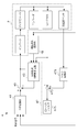
図3は、制御装置4の構成を示すブロック図である。図3において、制御対象Pは、図1及び図2を参照して説明したインバータ、ダイナモメータ本体、ロードセル、及び加速度センサ等を含んで構成される。制御装置4は、トルク電流指令信号に対する上位トルク指令信号を生成する上位制御部41と、上位制御部41から出力される上位トルク指令信号を補正するための補正信号を生成する固有振動抑制制御回路43と、ロードセルのロードセルトルク検出信号を補正する補正回路47と、エンコーダの角速度検出信号に基づいてダイナモメータ本体で発生する機械損失トルクに相当する損失補償信号を生成する機械損失演算部48と、トルク電流指令信号生成部49と、を備える。
上位制御部41は、図示しない処理によって定められた制御指令と、後述の補正回路47を経ることによってトルク脈動やノイズ等が除かれたロードセルトルク検出信号と、角度検出信号と、を用いることによって上位トルク指令信号を生成する。トルク電流指令信号生成部49は、上位制御部41によって生成された上位トルク指令信号から、後述の固有振動抑制制御回路43によって生成された補正信号を減算することによってトルク電流指令信号を生成し、これをインバータへ入力する。
補正回路47は、トルク変換部471と、加算部473と、ローパスフィルタ475と、を備える。トルク変換部471は、加速度センサの検出信号から所定の周波数以下の直流成分を除いた後、その位相を180度反転させ、さらに所定の係数を乗算することによってトルク信号を生成する。加算部473は、ロードセルトルク検出信号にトルク変換部471によって生成されたトルク信号を加算することにより、ロードセルトルク検出信号からトルク脈動成分を除去する。またローパスフィルタ475は、加算部473によって生成されたトルク信号から高調波のノイズを除去することにより、トルク脈動やノイズ等が除かれたロードセルトルク検出信号を、上位制御部41へ入力する。
機械損失演算部48は、角速度検出信号に基づいて、ダイナモメータシステム1における付帯機器であるローラ及びフライホイールが接続されている状態のダイナモメータ本体に発生する機械損失トルクを推定し、これを損失補償信号として出力する。
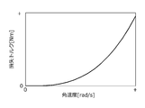
図4は、機械損失演算部48における演算結果の一例を示す図である。図4において横軸は機械損失演算部48の入力に相当する角速度[rad/s]であり、縦軸は機械損失演算部48の出力に相当する機械損失トルク[Nm]である。図4に示すように機械損失演算部48では、角速度の値が大きくなるほど機械損失トルクを大きな値にする。
固有振動抑制制御回路43は、インバータへのトルク電流指令信号と、後述の補正回路47を経ていないロードセルトルク検出信号と、機械損失演算部48によって生成される損失補償信号と、に基づいて、揺動子の固有振動が抑制されるように上位トルク指令信号に対する補正信号を生成する。
図5は、固有振動抑制制御回路43の構成を示すブロック図である。なお図4では、上位トルク指令信号を“Tdy_ref”と表記し、ロードセルトルク検出信号を“LC_det”と表記し、外乱トルクを“Dis”と表記し、角速度検出信号を“SPdy_det”と表記し、損失補償信号を“ML_ref”と表記する。
また制御対象Pは、インバータへの入力からロードセルの出力までの間における直流ゲイン特性及び振動特性を表す伝達関数“Pdc(s)”と、検出特性(ローパスフィルタ特性)を表す伝達関数“PF(s)”と、検出無駄時間特性を表す伝達関数“e-L・s(s)”と、を組み合わせて構成される。
固有振動抑制制御回路43は、制御対象Pに含まれる直流ゲイン特性、振動特性、検出特性、検出無駄時間特性、及び機械損失特性を考慮した演算を行うモデル補償回路431と、このモデル補償回路431において得られるトルク信号Pmdl_detに微分演算を施すことによって補正信号を生成する微分補償器437と、を備える。
微分補償器437の伝達関数“HLFP(s)”は、例えば下記式(1)に示すような擬似微分特性を有するものが用いられる。下記式(1)において、“ωn”は、揺動子の固有振動数である。また伝達関数“1/GLFP(s)”は、相対次数1以上の任意の関数である。また係数“K”は、任意の実数であり、その具体的な値は、揺動子の固有振動が抑制されるように0から1の範囲内で設定される。なお、このような微分補償器437を用いて生成した補正信号を用いて上位トルク指令信号を補正することにより、揺動子の固有振動が抑制される理由については、本願出願人による特開2013-246152号に記載されているので、ここでは詳細な説明を省略する。

モデル補償回路431は、制御対象Pにおける入力であるトルク電流指令信号から出力であるロードセルトルク検出信号までの特性を模した入出力特性を有する規範モデル演算部432と、規範モデル演算部432からの出力トルク信号LCmdl_detとロードセルトルク検出信号LC_detとの偏差errを用いて、この偏差errが小さくなるようなフィードバック信号を生成する偏差補償器433と、制御対象Pに入力されるトルク電流指令信号と偏差補償器433からのフィードバック信号と機械損失演算部48からの損失補償信号ML_refとを用いることによって規範モデル演算部432への入力トルク信号を生成するモデル入力生成部434と、を備える。
モデル入力生成部434は、制御対象Pへ入力されるトルク電流指令信号から機械損失演算部48からの損失補償信号ML_refを減算して得られるトルク信号に所定のゲインKdcを乗算する。このゲインKdcは、制御対象Pの直流ゲイン特性を補償するための定数である。またモデル入力生成部434は、ゲインKdcを乗じて得られるトルク信号と偏差補償器433からのフィードバック信号とを合算することによって規範モデル演算部432への入力トルク信号を生成する。
規範モデル演算部432は、制御対象Pにおける振動特性を模した演算を行う振動特性補償演算部432aと、検出特性を模した演算を行う検出特性補償演算部432bと、検出無駄時間特性を模した演算を行う無駄時間特性補償演算部432cと、を組み合わせて用いることにより、制御対象Pにおけるトルク電流指令信号からロードセルトルク検出信号までの特性を模した演算を行う。
振動特性補償演算部432aは、モデル入力生成部434からの入力トルク信号を、制御対象Pの振動特性を模した伝達関数Pmdl(s)に入力することによって得られるトルク信号Pmdl_detを検出特性補償演算部432b及び微分補償器437へ入力する。ここで振動特性補償演算部432aにおける伝達関数Pmld(s)には、揺動子の固有振動数ωn及びダンピング係数ζを用いた下記式(2)に示すような2次遅れ標準形で表されるものが用いられる。

検出特性補償演算部432bは、振動特性補償演算部432aからのトルク信号Pmdl_detを、制御対象Pの検出特性を模した伝達関数PF_mdl(s)に入力することによって得られるトルク信号を無駄時間特性補償演算部432cへ入力する。ここで検出特性補償演算部432bにおける伝達関数PF_mdl(s)には、ローパスフィルタ特性を有するものが用いられる。
無駄時間特性補償演算部432cは、検出特性補償演算部432bからのトルク信号を、制御対象Pの検出無駄時間特性を模した伝達関数e-Lmdl・sに入力することによって得られる信号を出力トルク信号LCmdl_detとして出力する。ここで“Lmdl”は、無駄時間であり予め定められた値が用いられる。
偏差補償器433は、規範モデル演算部432からの出力トルク信号LCmdl_detからロードセルトルク検出信号LC_detを減算して得られる偏差errが小さくなるようにフィードバック信号を出力する。この偏差補償器433の伝達関数“F(s)”は、例えば下記式(3)で表される。下記式(3)において、係数“KG”は調整ゲインであり、その具体的な値は0から1の範囲内で定められる。また下記式(3)において、伝達関数“1/FLPF(s)”は、相対次数1以上の任意の伝達関数である。

以上のような本実施形態に係るダイナモメータシステム1の制御装置4によれば、以下の効果を奏する。
(1)制御装置4では、上位トルク指令信号Tdy_refから、固有振動抑制制御回路43によって生成される補正信号を減算することによってトルク電流指令信号を生成し、これをローラ6L,6Rやフライホイール71~73等の負荷が接続されたダイナモメータ本体2のインバータ3へ入力する。揺動子21を備えたダイナモメータ本体2において、インバータ3への入力からロードセル28の出力までの伝達関数は2次遅れ標準形によって近似的に表現される。そこで固有振動抑制制御回路43では、ダイナモメータシステム1におけるトルク電流指令信号からロードセルトルク検出信号LC_detまでの特性を模した入出力特性を有する規範モデル演算部432で得られるトルク信号Pmdl_detに対し、微分補償器437で微分演算を施すことによって補正信号を生成し、上位トルク指令信号からこの補正信号を減算することによってトルク電流指令信号を生成する。制御装置4ではこのような補正信号を用いることにとり、揺動子21の固有振動を抑制するようにダイナモメータ本体2にダンピングを与えることができる。制御装置4では、このような微分補償器437を備えた固有振動抑制制御回路43を設けることにより、揺動子の固有振動そのものを抑制し、ひいてはロードセルトルク検出信号LC_detから不要なトルク変動成分を除去できる。したがって制御装置4によれば、カットオフ周波数の低いフィルタリング技術を用いることなくロードセル28から安定した検出信号を得ることができる。またこのような固有振動抑制制御回路43を用いて揺動子21の固有振動を抑制することにより、高応答で安定した制御を実現することができる。
(1)制御装置4では、上位トルク指令信号Tdy_refから、固有振動抑制制御回路43によって生成される補正信号を減算することによってトルク電流指令信号を生成し、これをローラ6L,6Rやフライホイール71~73等の負荷が接続されたダイナモメータ本体2のインバータ3へ入力する。揺動子21を備えたダイナモメータ本体2において、インバータ3への入力からロードセル28の出力までの伝達関数は2次遅れ標準形によって近似的に表現される。そこで固有振動抑制制御回路43では、ダイナモメータシステム1におけるトルク電流指令信号からロードセルトルク検出信号LC_detまでの特性を模した入出力特性を有する規範モデル演算部432で得られるトルク信号Pmdl_detに対し、微分補償器437で微分演算を施すことによって補正信号を生成し、上位トルク指令信号からこの補正信号を減算することによってトルク電流指令信号を生成する。制御装置4ではこのような補正信号を用いることにとり、揺動子21の固有振動を抑制するようにダイナモメータ本体2にダンピングを与えることができる。制御装置4では、このような微分補償器437を備えた固有振動抑制制御回路43を設けることにより、揺動子の固有振動そのものを抑制し、ひいてはロードセルトルク検出信号LC_detから不要なトルク変動成分を除去できる。したがって制御装置4によれば、カットオフ周波数の低いフィルタリング技術を用いることなくロードセル28から安定した検出信号を得ることができる。またこのような固有振動抑制制御回路43を用いて揺動子21の固有振動を抑制することにより、高応答で安定した制御を実現することができる。
またダイナモメータ本体2に負荷として接続される付帯機器の構成(例えば、フライホイールの組み合わせ)が変化すると、発生する機械損失も変化し、実機と規範モデル演算部432で規定される規範モデルとの間に誤差が生じてしまうおそれがある。そこで制御装置4の機械損失演算部48では、角速度検出信号SPdy_detに基づいて、付帯機器が接続されている状態のダイナモメータ本体2に発生する機械損失トルクに相当する損失補償信号ML_refを生成し、固有振動抑制制御回路43では、トルク電流指令信号と、ロードセルトルク検出信号LC_detと、損失補償信号ML_refと、を用いることによって補正信号を生成する。より具体的には、固有振動抑制制御回路43では、トルク電流指令信号から損失補償信号ML_refを減算して得られるトルク信号と、偏差補償器433によって算出されるフィードバック信号と、を用いて規範モデル演算部432への入力トルク信号を生成し、このような入力トルク信号を規範モデル演算部432に入力した場合に得られるトルク信号Pmdl_detを用いて補正信号を生成する。これにより、ダイナモメータ本体2に接続される付帯機器の構成が変化し、ひいては機械損失トルクが変化し、実機と規範モデル演算部432で規定される規範モデルとの間に誤差が生じた場合であっても、この誤差は損失補償信号ML_refによって補償される。したがって制御装置4によれば、ダイナモメータ本体2に接続される負荷が変化しても高応答で安定した制御が可能でありかつ高い精度で計測が可能となる。
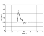
図6は、本実施形態の制御装置4の効果を検証するために行った試験の結果を示す図である。この試験では、上位トルク指令信号の値を200[Nm]とした定常状態において時刻3.9秒で外乱トルクを重畳した場合におけるロードセルトルク検出信号の変化を測定した。図6において破線は、機械損失演算部48によって算出した損失補償信号ML_refを固有振動抑制制御回路43に入力しなかった場合におけるロードセルトルク検出信号の変化を示し、実線は損失補償信号ML_refを固有振動抑制制御回路43に入力した場合におけるロードセルトルク検出信号の変化を示す。この図6に示すように、損失補償信号ML_refを入力することにより、ロードセルトルク検出信号の振幅を小さくすることができる。このため、本実施形態の制御装置4によれば、高応答で安定したトルク制御を実現することができる。
次に、実施例1の機械損失演算部について説明する。実施例1の機械損失演算部は、角速度検出信号の値とこの値に応じた損失補償信号の値との対応関係を定めたルックアップテーブルを格納する記憶媒体を備え、角速度検出信号SPdy_detの値を用いて上記ルックアップテーブルを検索することによって得られる値の損失補償信号ML_refを生成する。
上述のように、複数のフライホイール71~73は、ダイナモメータシステム1における複数の付帯機器を構成し、これらは適宜組み合わせてダイナモメータ本体2に接続することができる。そこで記憶媒体には、ダイナモメータ本体2と、このダイナモメータ本体2に接続される付帯機器との組み合わせ(本実施例では、複数のフライホイールの組み合わせ)毎に異なるルックアップテーブルを複数格納しておく。そして制御装置の利用時には、作業者が実際のダイナモメータ本体2に接続するフライホイールの組み合わせに応じて上記複数のルックアップテーブルのうちの1つを選択できるようにしておき、機械損失演算部は、角速度検出信号SPdy_detの値を用いて、作業者の操作によって選択されたルックアップテーブルを検索することによって得られる値の損失補償信号ML_refを生成する。
実施例1の機械損失演算部を用いた制御装置によれば、以下の効果を奏する。
(2)本実施例の機械損失演算部では、角速度検出信号SPdy_detの値を用いて、予め定められたルックアップテーブルを検索することによって損失補償信号ML_refを生成する。これにより、損失補償信号ML_refを速やかに生成することができる。
(2)本実施例の機械損失演算部では、角速度検出信号SPdy_detの値を用いて、予め定められたルックアップテーブルを検索することによって損失補償信号ML_refを生成する。これにより、損失補償信号ML_refを速やかに生成することができる。
(3)ダイナモメータ本体2に接続される付帯機器の組み合わせが変わると、ダイナモメータ本体で発生する機械損失の大きさも変化する。本実施例の機械損失演算部では、付帯機器の組み合わせ毎に異なるルックアップテーブルを記憶媒体に格納しておくことにより、ダイナモメータ本体に接続される付帯機器の組み合わせが変化した場合であっても、この変化に応じて適切な大きさの損失補償信号ML_refを容易に生成することができる。
次に、実施例2の機械損失演算部について説明する。実施例2の機械損失演算部は、角速度検出信号の値を入力とし、この入力に応じた損失補償信号の値を出力する演算式を格納する記憶媒体を備え、角速度検出信号SPdy_detの値をこの演算式に入力することによって得られる値の損失補償信号ML_refを生成する。
ここで演算式とは、例えば、下記式(4)に示すような角速度検出信号SPdy_detの2次式が用いられる。また下記式(4)において、“A”、“B”、“C”は、最小二乗法等の推定方法や既知の最適化法によって定められる係数である。

また実施例1の機械損失演算部と同様、記憶媒体には、ダイナモメータ本体2に接続される付帯機器の組み合わせ(本実施例では、複数のフライホイールの組み合わせ)毎に異なる演算式を複数格納しておく。そして制御装置の利用時には、作業者が実際のダイナモメータ本体2に接続する付帯機器の組み合わせに応じて上記複数の演算式のうちの1つを選択できるようにしておき、機械損失演算部は、角速度検出信号SPdy_detの値を、作業者の操作によって選択された演算式に入力することによって得られる値の損失補償信号ML_refを生成する。
実施例2の機械損失演算部を用いた制御装置によれば、以下の効果を奏する。
(4)本実施例の機械損失演算部では、角速度検出信号SPdy_detの値を、予め定められた演算式に入力することによって損失補償信号ML_refを生成する。これにより、損失補償信号ML_refを速やかに生成することができる。
(4)本実施例の機械損失演算部では、角速度検出信号SPdy_detの値を、予め定められた演算式に入力することによって損失補償信号ML_refを生成する。これにより、損失補償信号ML_refを速やかに生成することができる。
(5)本実施例の機械損失演算部では、ダイナモメータ本体2に接続する付帯機器の組み合わせ毎に異なる演算式を記憶媒体に格納しておくことにより、ダイナモメータ本体に接続される付帯機器の組み合わせが変化した場合であっても、この変化に応じて適切な大きさの損失補償信号ML_refを容易に生成することができる。
以上本発明の一実施形態について説明したが、本発明はこれに限らない。本発明の趣旨の範囲内で、細部の構成を適宜変更してもよい。
例えば上記実施形態では、本発明の制御装置を、車両を供試体とするシャシダイナモメータシステムに適用した場合について説明したが、本発明はこれに限らない。本発明の制御装置は、車両のエンジンを供試体とするエンジンベンチシステムや、車両のドライブトレインを供試体とするドライブトレインベンチシステムに適用することもできる。
例えば上記実施形態では、本発明の制御装置を、車両を供試体とするシャシダイナモメータシステムに適用した場合について説明したが、本発明はこれに限らない。本発明の制御装置は、車両のエンジンを供試体とするエンジンベンチシステムや、車両のドライブトレインを供試体とするドライブトレインベンチシステムに適用することもできる。
エンジンベンチシステムでは、ダイナモメータ本体の出力軸とエンジンの出力軸との間には中間軸が付帯機器として用いられる。このため、本発明の制御装置をエンジンベンチシステムに適用する場合、上記機械損失演算部の記憶媒体には、ダイナモメータ本体とこのダイナモメータ本体に接続される付帯機器との組み合わせ毎に異なるルックアップテーブルや演算式を格納しておくことにより、エンジンベンチシステムにおいても、上記(1)~(5)と同様の効果を奏する。
またドライブトレインベンチシステムでは、ダイナモメータ本体の出力軸とドライブトレインの入力軸との間には中間軸や増速器等が付帯機器として用いられる。このため、本発明の制御装置をドライブトレインベンチシステムに適用する場合、上記機械損失演算部の記憶媒体には、ダイナモメータ本体とこのダイナモメータ本体に接続される付帯機器との組み合わせ毎に異なるルックアップテーブルや演算式を格納しておくことにより、ドライブトレインベンチシステムにおいても、上記(1)~(5)と同様の効果を奏する。
1…ダイナモメータシステム
2…ダイナモメータ本体
21…揺動子
26…トルクアーム
28…ロードセル
29…エンコーダ(角速度センサ)
3…インバータ
4…制御装置
43…固有振動抑制制御回路
432…規範モデル演算部
433…偏差補償器
434…モデル入力生成部
437…微分補償器
49…トルク電流指令信号生成部
6L,6R…ローラ(負荷)
71,72,73…フライホイール(負荷)
2…ダイナモメータ本体
21…揺動子
26…トルクアーム
28…ロードセル
29…エンコーダ(角速度センサ)
3…インバータ
4…制御装置
43…固有振動抑制制御回路
432…規範モデル演算部
433…偏差補償器
434…モデル入力生成部
437…微分補償器
49…トルク電流指令信号生成部
6L,6R…ローラ(負荷)
71,72,73…フライホイール(負荷)
Claims (5)
- 揺動式のダイナモメータ本体と、当該ダイナモメータ本体の出力軸に接続された負荷と、トルク電流指令信号に応じて前記ダイナモメータ本体に電力を供給するインバータと、前記ダイナモメータ本体の揺動子に発生するトルクを、当該揺動子から延びるトルクアームを介して検出するトルクセンサと、前記出力軸の角速度を検出する角速度センサと、を備えるダイナモメータシステムの制御装置であって、
前記角速度センサの検出信号に基づいて、前記負荷が接続されている状態の前記ダイナモメータ本体で発生する損失トルクに相当する損失補償信号を生成する損失演算部と、
前記トルク電流指令信号、前記トルクセンサの検出信号、及び前記損失補償信号を用いることによって前記揺動子の固有振動が抑制されるように上位トルク指令信号に対する補正信号を生成する固有振動抑制制御回路と、
前記上位トルク指令信号から前記補正信号を減算することによって生成した前記トルク電流指令信号を前記インバータへ入力するトルク電流指令信号生成部と、を備え、
前記固有振動抑制制御回路は、
前記ダイナモメータシステムにおける前記トルク電流指令信号から前記トルクセンサの検出信号までの特性を模した入出力特性を有する規範モデル演算部と、
前記規範モデル演算部からの出力トルク信号と前記トルクセンサの検出信号との偏差を用いて当該偏差が小さくなるようなフィードバック信号を生成する偏差補償器と、
前記トルク電流指令信号から前記損失補償信号を減算して得られるトルク信号と前記フィードバック信号とを用いて前記規範モデル演算部への入力トルク信号を生成するモデル入力生成部と、
前記規範モデル演算部で得られるトルク信号に微分演算を施すことによって前記補正信号を生成する微分補償器と、を備えることを特徴とするダイナモメータシステムの制御装置。 - 前記損失演算部は、前記角速度センサの検出信号の値と当該値に応じた前記損失補償信号の値との対応関係を定めたルックアップテーブルを格納する記憶媒体を備え、前記角速度センサの検出信号の値を用いて前記ルックアップテーブルを検索することによって得られる値の前記損失補償信号を生成することを特徴とする請求項1に記載のダイナモメータシステムの制御装置。
- 前記負荷は前記出力軸に接続される1又は複数の付帯機器を含み、
前記記憶媒体には、前記ダイナモメータ本体と当該ダイナモメータ本体に接続される前記付帯機器との組合せ毎に異なる前記ルックアップテーブルが複数格納され、
前記損失演算部は、作業者の操作に応じて前記複数のルックアップテーブルのうちの1つを選択し、前記角速度センサの検出信号の値を用いて前記選択したルックアップテーブルを検索することによって得られる値の前記損失補償信号を生成することを特徴とする請求項2に記載のダイナモメータシステムの制御装置。 - 前記損失演算部は、前記角速度センサの検出信号の値を入力とし当該入力に応じた前記損失補償信号の値を出力とする演算式を格納する記憶媒体を備え、前記角速度センサの検出信号の値を前記演算式に入力することによって得られる値の前記損失補償信号を生成することを特徴とする請求項1に記載のダイナモメータシステムの制御装置。
- 前記負荷は前記出力軸に接続される1又は複数の付帯機器を備え、
前記記憶媒体には、前記ダイナモメータ本体と当該ダイナモメータ本体に接続される前記付帯機器との組み合わせ毎に異なる前記演算式が複数格納され、
前記損失演算部は、作業者の操作に応じて前記複数の演算式のうちの1つを選択し、前記角速度センサの検出信号の値を前記選択した演算式に入力することによって得られる値の前記損失補償信号を生成することを特徴とする請求項4に記載のダイナモメータシステムの制御装置。
Priority Applications (2)
| Application Number | Priority Date | Filing Date | Title |
|---|---|---|---|
| KR1020197034672A KR102139240B1 (ko) | 2017-05-09 | 2018-05-09 | 다이나모미터 시스템의 제어 장치 |
| US16/613,087 US11073437B2 (en) | 2017-05-09 | 2018-05-09 | Dynamometer system control device |
Applications Claiming Priority (2)
| Application Number | Priority Date | Filing Date | Title |
|---|---|---|---|
| JP2017-092819 | 2017-05-09 | ||
| JP2017092819A JP6369596B1 (ja) | 2017-05-09 | 2017-05-09 | ダイナモメータシステムの制御装置 |
Publications (1)
| Publication Number | Publication Date |
|---|---|
| WO2018207832A1 true WO2018207832A1 (ja) | 2018-11-15 |
Family
ID=63104303
Family Applications (1)
| Application Number | Title | Priority Date | Filing Date |
|---|---|---|---|
| PCT/JP2018/017967 Ceased WO2018207832A1 (ja) | 2017-05-09 | 2018-05-09 | ダイナモメータシステムの制御装置 |
Country Status (4)
| Country | Link |
|---|---|
| US (1) | US11073437B2 (ja) |
| JP (1) | JP6369596B1 (ja) |
| KR (1) | KR102139240B1 (ja) |
| WO (1) | WO2018207832A1 (ja) |
Cited By (1)
| Publication number | Priority date | Publication date | Assignee | Title |
|---|---|---|---|---|
| JP7371730B1 (ja) | 2022-06-15 | 2023-10-31 | 株式会社明電舎 | ダイナモメータシステム |
Families Citing this family (7)
| Publication number | Priority date | Publication date | Assignee | Title |
|---|---|---|---|---|
| KR102256390B1 (ko) * | 2018-09-07 | 2021-05-26 | 메이덴샤 코포레이션 | 동력계 제어 장치 |
| JP6638869B1 (ja) * | 2018-09-07 | 2020-01-29 | 株式会社明電舎 | 動力計制御装置 |
| JP7040581B1 (ja) * | 2020-09-29 | 2022-03-23 | 株式会社明電舎 | 試験システム |
| CN114763950A (zh) * | 2020-12-31 | 2022-07-19 | 青岛海尔智能技术研发有限公司 | 用于变频压缩机的转矩补偿方法及系统、热水器 |
| CN118424392B (zh) * | 2024-07-04 | 2024-11-12 | 中科微至科技股份有限公司 | 电动辊筒运行监测方法和系统 |
| WO2026018382A1 (ja) | 2024-07-18 | 2026-01-22 | 株式会社Tmeic | シャーシダイナモメータ |
| CN121612587B (zh) * | 2026-01-22 | 2026-04-14 | 常州大学怀德学院 | 基于双编码器差分的齿轮传动回差动态测量方法及其系统 |
Citations (4)
| Publication number | Priority date | Publication date | Assignee | Title |
|---|---|---|---|---|
| US4680959A (en) * | 1986-04-23 | 1987-07-21 | General Motors Corporation | Emulation system for a motor vehicle drivetrain |
| JP2009287987A (ja) * | 2008-05-28 | 2009-12-10 | Meidensha Corp | 動力計の電気慣性制御方式 |
| JP2010019652A (ja) * | 2008-07-10 | 2010-01-28 | Meidensha Corp | エンジンベンチシステムの動力計制御方式 |
| JP2016520841A (ja) * | 2013-06-03 | 2016-07-14 | アー・ファウ・エル・リスト・ゲゼルシャフト・ミト・ベシュレンクテル・ハフツング | テストベンチにおいて振動を減少させるための方法 |
Family Cites Families (7)
| Publication number | Priority date | Publication date | Assignee | Title |
|---|---|---|---|---|
| JP4826088B2 (ja) | 2004-12-28 | 2011-11-30 | 株式会社明電舎 | 油圧浮揚式電気動力計 |
| KR101921173B1 (ko) * | 2011-04-12 | 2018-11-22 | 고쿠사이 게이소쿠키 가부시키가이샤 | 회전 비틀림 시험기 |
| US9400508B2 (en) * | 2011-04-15 | 2016-07-26 | Meidensha Corporation | Periodicity disturbance suppression device and periodicity disturbance suppression method |
| JP5605383B2 (ja) * | 2012-02-29 | 2014-10-15 | 株式会社明電舎 | ダイナモメータシステム |
| JP5541314B2 (ja) | 2012-05-29 | 2014-07-09 | 株式会社明電舎 | ダイナモメータシステムの制御装置 |
| WO2015136626A1 (ja) * | 2014-03-11 | 2015-09-17 | 株式会社明電舎 | ドライブトレインの試験システム |
| JP6044649B2 (ja) * | 2015-01-19 | 2016-12-14 | 株式会社明電舎 | ダイナモメータシステムの制御装置 |
-
2017
- 2017-05-09 JP JP2017092819A patent/JP6369596B1/ja active Active
-
2018
- 2018-05-09 US US16/613,087 patent/US11073437B2/en active Active
- 2018-05-09 WO PCT/JP2018/017967 patent/WO2018207832A1/ja not_active Ceased
- 2018-05-09 KR KR1020197034672A patent/KR102139240B1/ko active Active
Patent Citations (4)
| Publication number | Priority date | Publication date | Assignee | Title |
|---|---|---|---|---|
| US4680959A (en) * | 1986-04-23 | 1987-07-21 | General Motors Corporation | Emulation system for a motor vehicle drivetrain |
| JP2009287987A (ja) * | 2008-05-28 | 2009-12-10 | Meidensha Corp | 動力計の電気慣性制御方式 |
| JP2010019652A (ja) * | 2008-07-10 | 2010-01-28 | Meidensha Corp | エンジンベンチシステムの動力計制御方式 |
| JP2016520841A (ja) * | 2013-06-03 | 2016-07-14 | アー・ファウ・エル・リスト・ゲゼルシャフト・ミト・ベシュレンクテル・ハフツング | テストベンチにおいて振動を減少させるための方法 |
Cited By (4)
| Publication number | Priority date | Publication date | Assignee | Title |
|---|---|---|---|---|
| JP7371730B1 (ja) | 2022-06-15 | 2023-10-31 | 株式会社明電舎 | ダイナモメータシステム |
| WO2023243638A1 (ja) * | 2022-06-15 | 2023-12-21 | 株式会社明電舎 | ダイナモメータシステム |
| JP2023183279A (ja) * | 2022-06-15 | 2023-12-27 | 株式会社明電舎 | ダイナモメータシステム |
| US12442702B2 (en) | 2022-06-15 | 2025-10-14 | Meidensha Corporation | Dynamometer system |
Also Published As
| Publication number | Publication date |
|---|---|
| US20200200627A1 (en) | 2020-06-25 |
| JP2018190214A (ja) | 2018-11-29 |
| JP6369596B1 (ja) | 2018-08-08 |
| KR102139240B1 (ko) | 2020-07-29 |
| US11073437B2 (en) | 2021-07-27 |
| KR20190136102A (ko) | 2019-12-09 |
Similar Documents
| Publication | Publication Date | Title |
|---|---|---|
| JP6369596B1 (ja) | ダイナモメータシステムの制御装置 | |
| JP5541314B2 (ja) | ダイナモメータシステムの制御装置 | |
| JP2013181904A (ja) | ダイナモメータシステム | |
| KR102069653B1 (ko) | 전기 관성 제어 장치 | |
| JP5935853B2 (ja) | ダイナモメータシステムの制御装置 | |
| JP6687086B1 (ja) | 電気慣性制御装置 | |
| US7263897B2 (en) | Three-axis motion table | |
| JP2013053910A (ja) | 動力伝達系の試験装置 | |
| JP2010043940A (ja) | 動力伝達系の試験装置およびその制御方法 | |
| JP5895405B2 (ja) | エンジンベンチシステムの制御装置 | |
| KR101784166B1 (ko) | 요동식 다이나모미터 시스템 및 그의 제어 방법 | |
| US12442702B2 (en) | Dynamometer system | |
| JP5200713B2 (ja) | 動力計測システムの速度制御方法とその装置 | |
| WO2015186616A1 (ja) | シャシーダイナモメータの制御装置 | |
| JP7633924B2 (ja) | モータ試験装置およびモータ試験方法 | |
| JP2009288036A (ja) | ローラ表面駆動力の推定方法とその装置 | |
| JP2007252036A (ja) | モータ制御装置 | |
| JP5812229B1 (ja) | シャシーダイナモメータの制御装置 | |
| JP5200714B2 (ja) | 電気慣性制御装置 |
Legal Events
| Date | Code | Title | Description |
|---|---|---|---|
| 121 | Ep: the epo has been informed by wipo that ep was designated in this application |
Ref document number: 18798523 Country of ref document: EP Kind code of ref document: A1 |
|
| NENP | Non-entry into the national phase |
Ref country code: DE |
|
| ENP | Entry into the national phase |
Ref document number: 20197034672 Country of ref document: KR Kind code of ref document: A |
|
| 122 | Ep: pct application non-entry in european phase |
Ref document number: 18798523 Country of ref document: EP Kind code of ref document: A1 |