WO2018207606A1 - スプレーチャンバー、試料霧化導入装置、分析装置および試料中の成分分析方法 - Google Patents
スプレーチャンバー、試料霧化導入装置、分析装置および試料中の成分分析方法 Download PDFInfo
- Publication number
- WO2018207606A1 WO2018207606A1 PCT/JP2018/016508 JP2018016508W WO2018207606A1 WO 2018207606 A1 WO2018207606 A1 WO 2018207606A1 JP 2018016508 W JP2018016508 W JP 2018016508W WO 2018207606 A1 WO2018207606 A1 WO 2018207606A1
- Authority
- WO
- WIPO (PCT)
- Prior art keywords
- spray chamber
- sample
- pipe
- additional gas
- tube portion
- Prior art date
- Legal status (The legal status is an assumption and is not a legal conclusion. Google has not performed a legal analysis and makes no representation as to the accuracy of the status listed.)
- Ceased
Links
Images


Classifications
-
- G—PHYSICS
- G01—MEASURING; TESTING
- G01N—INVESTIGATING OR ANALYSING MATERIALS BY DETERMINING THEIR CHEMICAL OR PHYSICAL PROPERTIES
- G01N27/00—Investigating or analysing materials by the use of electric, electrochemical, or magnetic means
- G01N27/62—Investigating or analysing materials by the use of electric, electrochemical, or magnetic means by investigating the ionisation of gases, e.g. aerosols; by investigating electric discharges, e.g. emission of cathode
- G01N27/622—Ion mobility spectrometry
- G01N27/623—Ion mobility spectrometry combined with mass spectrometry
-
- B—PERFORMING OPERATIONS; TRANSPORTING
- B05—SPRAYING OR ATOMISING IN GENERAL; APPLYING FLUENT MATERIALS TO SURFACES, IN GENERAL
- B05B—SPRAYING APPARATUS; ATOMISING APPARATUS; NOZZLES
- B05B7/00—Spraying apparatus for discharge of liquids or other fluent materials from two or more sources, e.g. of liquid and air, of powder and gas
- B05B7/24—Spraying apparatus for discharge of liquids or other fluent materials from two or more sources, e.g. of liquid and air, of powder and gas with means, e.g. a container, for supplying liquid or other fluent material to a discharge device
- B05B7/2402—Apparatus to be carried on or by a person, e.g. by hand; Apparatus comprising containers fixed to the discharge device
- B05B7/2405—Apparatus to be carried on or by a person, e.g. by hand; Apparatus comprising containers fixed to the discharge device using an atomising fluid as carrying fluid for feeding, e.g. by suction or pressure, a carried liquid from the container to the nozzle
- B05B7/2408—Apparatus to be carried on or by a person, e.g. by hand; Apparatus comprising containers fixed to the discharge device using an atomising fluid as carrying fluid for feeding, e.g. by suction or pressure, a carried liquid from the container to the nozzle characterised by the container or its attachment means to the spray apparatus
-
- B—PERFORMING OPERATIONS; TRANSPORTING
- B05—SPRAYING OR ATOMISING IN GENERAL; APPLYING FLUENT MATERIALS TO SURFACES, IN GENERAL
- B05B—SPRAYING APPARATUS; ATOMISING APPARATUS; NOZZLES
- B05B7/00—Spraying apparatus for discharge of liquids or other fluent materials from two or more sources, e.g. of liquid and air, of powder and gas
- B05B7/0012—Apparatus for achieving spraying before discharge from the apparatus
-
- B—PERFORMING OPERATIONS; TRANSPORTING
- B05—SPRAYING OR ATOMISING IN GENERAL; APPLYING FLUENT MATERIALS TO SURFACES, IN GENERAL
- B05B—SPRAYING APPARATUS; ATOMISING APPARATUS; NOZZLES
- B05B7/00—Spraying apparatus for discharge of liquids or other fluent materials from two or more sources, e.g. of liquid and air, of powder and gas
- B05B7/24—Spraying apparatus for discharge of liquids or other fluent materials from two or more sources, e.g. of liquid and air, of powder and gas with means, e.g. a container, for supplying liquid or other fluent material to a discharge device
- B05B7/2489—Spraying apparatus for discharge of liquids or other fluent materials from two or more sources, e.g. of liquid and air, of powder and gas with means, e.g. a container, for supplying liquid or other fluent material to a discharge device an atomising fluid, e.g. a gas, being supplied to the discharge device
- B05B7/2497—Spraying apparatus for discharge of liquids or other fluent materials from two or more sources, e.g. of liquid and air, of powder and gas with means, e.g. a container, for supplying liquid or other fluent material to a discharge device an atomising fluid, e.g. a gas, being supplied to the discharge device several liquids from different sources being supplied to the discharge device
-
- G—PHYSICS
- G01—MEASURING; TESTING
- G01N—INVESTIGATING OR ANALYSING MATERIALS BY DETERMINING THEIR CHEMICAL OR PHYSICAL PROPERTIES
- G01N21/00—Investigating or analysing materials by the use of optical means, i.e. using sub-millimetre waves, infrared, visible or ultraviolet light
- G01N21/62—Systems in which the material investigated is excited whereby it emits light or causes a change in wavelength of the incident light
- G01N21/71—Systems in which the material investigated is excited whereby it emits light or causes a change in wavelength of the incident light thermally excited
- G01N21/714—Sample nebulisers for flame burners or plasma burners
-
- H—ELECTRICITY
- H01—ELECTRIC ELEMENTS
- H01J—ELECTRIC DISCHARGE TUBES OR DISCHARGE LAMPS
- H01J49/00—Particle spectrometers or separator tubes
- H01J49/02—Details
- H01J49/04—Arrangements for introducing or extracting samples to be analysed, e.g. vacuum locks; Arrangements for external adjustment of electron- or ion-optical components
-
- H—ELECTRICITY
- H01—ELECTRIC ELEMENTS
- H01J—ELECTRIC DISCHARGE TUBES OR DISCHARGE LAMPS
- H01J49/00—Particle spectrometers or separator tubes
- H01J49/02—Details
- H01J49/04—Arrangements for introducing or extracting samples to be analysed, e.g. vacuum locks; Arrangements for external adjustment of electron- or ion-optical components
- H01J49/0431—Arrangements for introducing or extracting samples to be analysed, e.g. vacuum locks; Arrangements for external adjustment of electron- or ion-optical components for liquid samples
- H01J49/0445—Arrangements for introducing or extracting samples to be analysed, e.g. vacuum locks; Arrangements for external adjustment of electron- or ion-optical components for liquid samples with means for introducing as a spray, a jet or an aerosol
-
- H—ELECTRICITY
- H01—ELECTRIC ELEMENTS
- H01J—ELECTRIC DISCHARGE TUBES OR DISCHARGE LAMPS
- H01J49/00—Particle spectrometers or separator tubes
- H01J49/02—Details
- H01J49/04—Arrangements for introducing or extracting samples to be analysed, e.g. vacuum locks; Arrangements for external adjustment of electron- or ion-optical components
- H01J49/0431—Arrangements for introducing or extracting samples to be analysed, e.g. vacuum locks; Arrangements for external adjustment of electron- or ion-optical components for liquid samples
- H01J49/0445—Arrangements for introducing or extracting samples to be analysed, e.g. vacuum locks; Arrangements for external adjustment of electron- or ion-optical components for liquid samples with means for introducing as a spray, a jet or an aerosol
- H01J49/045—Arrangements for introducing or extracting samples to be analysed, e.g. vacuum locks; Arrangements for external adjustment of electron- or ion-optical components for liquid samples with means for introducing as a spray, a jet or an aerosol with means for using a nebulising gas, i.e. pneumatically assisted
-
- H—ELECTRICITY
- H01—ELECTRIC ELEMENTS
- H01J—ELECTRIC DISCHARGE TUBES OR DISCHARGE LAMPS
- H01J49/00—Particle spectrometers or separator tubes
- H01J49/02—Details
- H01J49/10—Ion sources; Ion guns
-
- H—ELECTRICITY
- H01—ELECTRIC ELEMENTS
- H01J—ELECTRIC DISCHARGE TUBES OR DISCHARGE LAMPS
- H01J49/00—Particle spectrometers or separator tubes
- H01J49/02—Details
- H01J49/10—Ion sources; Ion guns
- H01J49/105—Ion sources; Ion guns using high-frequency excitation, e.g. microwave excitation, Inductively Coupled Plasma [ICP]
-
- B—PERFORMING OPERATIONS; TRANSPORTING
- B05—SPRAYING OR ATOMISING IN GENERAL; APPLYING FLUENT MATERIALS TO SURFACES, IN GENERAL
- B05B—SPRAYING APPARATUS; ATOMISING APPARATUS; NOZZLES
- B05B7/00—Spraying apparatus for discharge of liquids or other fluent materials from two or more sources, e.g. of liquid and air, of powder and gas
- B05B7/24—Spraying apparatus for discharge of liquids or other fluent materials from two or more sources, e.g. of liquid and air, of powder and gas with means, e.g. a container, for supplying liquid or other fluent material to a discharge device
- B05B7/2402—Apparatus to be carried on or by a person, e.g. by hand; Apparatus comprising containers fixed to the discharge device
- B05B7/2405—Apparatus to be carried on or by a person, e.g. by hand; Apparatus comprising containers fixed to the discharge device using an atomising fluid as carrying fluid for feeding, e.g. by suction or pressure, a carried liquid from the container to the nozzle
- B05B7/2424—Apparatus to be carried on or by a person, e.g. by hand; Apparatus comprising containers fixed to the discharge device using an atomising fluid as carrying fluid for feeding, e.g. by suction or pressure, a carried liquid from the container to the nozzle the carried liquid and the main stream of atomising fluid being brought together downstream of the container before discharge
Definitions
- the present invention relates to a spray chamber, a sample atomization introducing device, an analysis device, and a component analysis method in a sample.
- a sample atomization introduction apparatus including a nebulizer (atomizer) and a spray chamber is provided in various analysis apparatuses (for example, JP-A-6-102249). (The entire description is specifically incorporated herein by reference).
- the sample liquid is formed into droplets in the nebulizer.
- the spray chamber can serve to sort the particle size of the sample droplet.
- the spray chamber mainly uses the difference in weight due to the difference in the particle size of the droplets to select the particle size of the sample droplets by the difference in gravity, and the fine droplets are used as the analysis unit of the analyzer. Can play a role to introduce.
- the analysis sensitivity for example, signal intensity
- the analysis unit of the analysis apparatus including the sample atomization introduction device and the analysis unit is proportional to the sample introduction efficiency. Therefore, it is desirable to reduce the sample droplet loss in the spray chamber and introduce more droplets into the analysis unit in order to improve analysis sensitivity.
- One embodiment of the present invention provides a new means for enabling high sensitivity of an analyzer for analyzing a sample by introducing a sample droplet.
- One embodiment of the present invention provides: A sample inlet port through which a gas flow containing sample droplets atomized by a nebulizer is introduced; An outlet for discharging at least a part of the gas flow introduced into the sample inlet; A flow path tube section having the sample introduction port portion at one end and the discharge port portion at the other end, and serving as a flow path for the introduced gas flow; Have The flow path tube portion has a first tube portion having the discharge port portion at one end, and a second tube portion having the sample introduction port portion at one end portion, The first pipe portion has a cylindrical portion including an end opposite to the end having the discharge port portion, and has a conical portion whose inner diameter decreases toward the discharge port portion.
- the second tube portion has a cylindrical portion including an end opposite to the end having the sample introduction port portion, and the outer diameter of the cylindrical portion of the second tube portion is the cylinder of the first tube portion. Smaller than the inner diameter of the part, Having a double pipe part configured by overlapping the cylindrical part of the first pipe part and the cylindrical part of the second pipe part at least partially; A spray chamber having an additional gas introduction opening on the outer side surface of the double pipe section and an additional gas introduction pipe section serving as an introduction path for introducing additional gas into the double pipe section through the additional gas introduction opening , About.
- the angle formed by the central axis direction of the additional gas introduction pipe section and the central axis direction of the cylindrical section of the first pipe section may be in the range of 90 ° to 130 °.
- the additional gas introduction opening may be located at a position near the second pipe portion on the outer side surface of the double pipe portion.
- the length of the double tube portion may be in the range of 10.0 mm to 30.0 mm.
- the difference between the inner diameter of the cylindrical portion of the first tube portion and the outer diameter of the cylindrical portion of the second tube portion may be in the range of 1.0 mm to 6.0 mm.
- the ratio (length / maximum inner diameter) of the length of the conical portion of the first tube portion to the maximum inner diameter of the conical portion may be in the range of 0.5 to 3.0.
- the spray chamber may have a total length in the range of 80.0 mm to 200.0 mm.
- the angle formed between the central axis direction of the sample introduction port portion and the central axis direction of the cylindrical portion of the first tube portion may be in the range of 10 ° to 60 °.
- the central axis direction of the sample introduction port portion and the central axis direction of the cylindrical portion of the first tube portion may be the same direction.
- the first tube portion and the second tube portion can be made of glass, quartz, or a fluororesin member.
- a waste liquid pipe portion serving as a waste liquid passage for draining liquid from the inside of the double pipe portion to the outside through the waste liquid opening and the waste liquid opening can be provided on the outer side surface of the double pipe portion.
- a further aspect of the present invention relates to a sample atomization introducing apparatus including the spray chamber and the nebulizer.
- a further aspect of the present invention relates to an analysis apparatus including the sample atomization introduction apparatus and the analysis unit.
- the angle formed by the horizontal direction of the installation surface on which the sample atomization introducing apparatus is installed and the central axis direction of the cylindrical portion of the first tube portion of the spray chamber is in the range of 20 ° to 90 °. Can be.
- the analysis device may be an inductively coupled plasma analysis device, and the analysis unit may include a plasma torch.
- the analyzer can be an inductively coupled plasma mass spectrometer.
- a further aspect of the invention provides: Analyzing the components in the sample liquid to be analyzed by the analyzer.
- the method further includes introducing additional gas from the additional gas introduction tube portion.
- the present invention relates to a method for analyzing components in a sample solution.
- a spray chamber that can contribute to high sensitivity of an analyzer. Furthermore, according to one aspect of the present invention, there is provided a sample atomization introducing apparatus including the spray chamber, an analysis apparatus including the sample atomization introducing apparatus, and a method for analyzing a component in a sample liquid using the analysis apparatus. it can.
- a spray chamber includes a sample introduction port portion into which a gas flow containing sample droplets atomized by a nebulizer is introduced, and at least a part of the gas flow introduced into the sample introduction port portion.
- the flow channel tube portion includes a first tube portion having the discharge port portion at one end portion and a second tube portion having the sample introduction port portion at one end portion.
- the first pipe portion has a cylindrical portion including an end opposite to the end having the discharge port portion, and has a conical portion whose inner diameter decreases toward the discharge port portion.
- the second tube portion has a cylindrical portion including an end opposite to the end having the sample introduction port.
- the outer diameter of the cylindrical part of the second pipe part is smaller than the inner diameter of the cylindrical part of the first pipe part.
- the spray chamber has a double pipe part configured by overlapping at least part of the cylindrical part of the first pipe part and the cylindrical part of the second pipe part, On the outer side surface, there are an additional gas introduction opening and an additional gas introduction pipe section that serves as an introduction path for introducing additional gas into the double pipe section through the additional gas introduction opening.
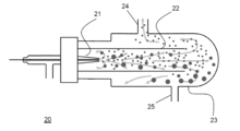
- FIG. 5 is a schematic view (side view) showing an example of a Scott type spray chamber widely used as a spray chamber of an inductively coupled plasma analyzer.
- Scott type spray chamber Scott double pass spray chamber
- sample droplets generated by atomizing the sample liquid in the nebulizer 21 are introduced as a gas flow together with the carrier gas.
- the Scott type spray chamber 20 is a tubular member having a double tube structure as a whole, and a gas flow containing a sample droplet is introduced from the nebulizer into the inner tube 22 of the double tube.
- a droplet having a small particle size and a droplet having a large particle size are selected by a difference in gravity by using a difference in droplet weight due to a difference in droplet particle size.
- the droplet having a small particle diameter is discharged from the upper part of the spray chamber through the outer tube 23 of the double tube (from the discharge port 24 in the embodiment shown in FIG. 5) and introduced into the analysis unit.
- a droplet having a large particle size falls downward in the spray chamber, and in the embodiment shown in FIG. 5, the liquid is discharged from the waste liquid port 25 provided below the spray chamber to the outside of the spray chamber.
- the Scott type spray chamber is generally said to have a high particle size sorting ability based on the difference in gravity because the gas flow path containing the sample droplets is longer than other types of spray chambers.
- the droplets adhere to the wall surface inside the spray chamber and the loss of the wall surface of the droplet occurs, which reduces the efficiency of introducing the sample into the analysis section. It is thought to cause.
- the additional gas introduced from the double pipe portion can contribute to reducing the wall surface deposition loss of the sample droplet.
- the additional gas introduced into the double pipe section brings about an additional gas flow that spirally swirls along the wall surface from the double pipe section toward the conical section of the first pipe section.
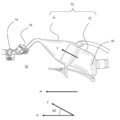
- FIG. 1 is a schematic view (side view) showing an example of a spray chamber according to one embodiment of the present invention.
- a spray chamber 10 shown in FIG. 1 includes a flow channel tube portion 13 including a first tube portion 11 and a second tube portion 12.
- tube part 11 is connected with the analysis part mentioned later for details.
- the first tube portion 11 is connected to the inlet portion 14 of the plasma torch, which is the portion closest to the spray chamber of the analysis portion, via a joint member 15.
- the second pipe portion 12 is connected to the nebulizer 16.
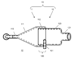
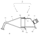
- FIGS. 2A and 2B are schematic views showing only the spray chamber. 2A is a top view and FIG. 2B is a side view. In the figure, the dotted line indicates the thickness and does not indicate a double tube.
- the spray chamber 10 shown in FIGS. 2A and 2B is composed of a flow path tube portion 13 having a discharge port portion 110 at one end portion and a sample introduction port portion 121 at the other end portion.
- the flow path pipe part 13 is composed of a first pipe part 11 and a second pipe part 12.
- the first pipe part 11 includes a discharge port part 110, a conical part 111 and a cylindrical part 112.
- the second tube portion 12 includes a cylindrical portion 120 and a sample introduction tube portion 121.
- the cylindrical part 112 of the 1st pipe part 11 and the cylindrical part 120 of the 2nd pipe part 12 overlap and connect with at least one part, and the double pipe part 100 is comprised.
- the inner wall surface of the double tube space of the double tube portion 100 is the outer side surface of the cylindrical portion 120 of the second tube portion 12, and the outer wall surface of the double tube space of the double tube portion 100 is the first wall surface. It is a wall surface of the cylindrical portion 112 of the one pipe portion 11.
- the first pipe portion 11 has a discharge port portion 110 at one end portion, and the discharge port portion 110 communicates with the conical portion 111.
- the conical part 111 has a conical shape whose inner diameter decreases toward the discharge port part.
- the conical part 111 communicates with a cylindrical part 112 including the other end of the first pipe part.
- a cylindrical portion 120 including one end portion of the second tube portion and a sample introduction port portion 121 including the other end portion communicate with each other.
- the first tube portion 11 and the second tube portion 12 having the above structure constitute a flow channel tube portion 13.
- the cylindrical part of both pipe parts overlaps and the double pipe part 100 is comprised.
- the double pipe part is a part between the end opening of the cylindrical part of the first pipe part and the end opening of the cylindrical part of the second pipe part. Therefore, although both ends of the double tube portion are openings, a virtual plane surrounded by the openings is hereinafter referred to as a bottom surface.
- the first tube portion 11 and the second tube portion 12 are separate members, and the end portion of the cylindrical portion 112 of the first tube portion 11 has an opening at the end of the second tube portion 12.
- the cylindrical portion 112 of the first tube portion 11 is tapered at the end, and the inner diameter of the tapered end opening is substantially the same as the outer diameter of the end opening of the cylindrical portion 120 of the second tube portion 12.
- the sealing of the connection part it is not essential to completely prevent the leakage of additional gas, and leakage that does not prevent the additional gas introduced into the double pipe part from flowing as a gas flow is allowed.
- the flow path pipe portion may be formed by integrally molding the first pipe portion and the second pipe portion.
- the double pipe portion 100 has an opening on the outer side surface, that is, the outer side surface of the cylindrical portion 112 of the first pipe portion 11.
- This opening is an opening (additional gas introduction opening) for introducing additional gas into the double pipe portion (that is, a space surrounded by the inner wall surface and the outer wall surface of the double tube portion).
- the additional gas introduction pipe section 101 serves as an introduction path for introducing additional gas into the double pipe section through the opening.
- the presence of a conical portion whose inner diameter decreases toward the discharge port side of the spray chamber can also contribute to the spiral gas flow of the additional gas flow.
- the additional gas flow generated in this manner can be a gas flow spirally toward the discharge port along the wall surface of the conical portion.
- the cylindrical part 112 of the first pipe part 11 has a waste liquid pipe part 113 for waste liquid through the waste liquid opening and the waste liquid opening in addition to the additional gas introduction opening.
- the waste liquid pipe part 113 can serve as a waste liquid path for waste liquid from the inside of the double pipe part 100 to the outside.
- the second pipe part 12 also has a waste liquid pipe part 122.
- the waste liquid pipe part 122 can serve as a waste liquid path for waste liquid from the inside of the second pipe part 12 to the outside.
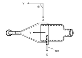
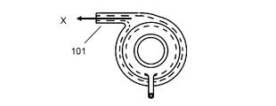
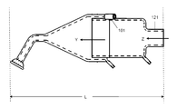
- FIGS. 3A to 3C are explanatory views of the arrangement of the additional gas introduction pipe portion in the spray chamber shown in FIGS. 2A and 2B.
- 3A is a drawing showing an explanatory arrow in the top view shown in FIG. 2A
- FIG. 3B is a cross-sectional view of a portion including an additional gas introduction pipe portion of a double pipe portion.
- FIG. 3C is a diagram showing arrows for explanation in the side view shown in FIG. 2B.
- the arrows in the figure indicate the following directions, respectively.
- the X direction is the central axis direction of the additional gas introduction pipe section.
- the Y direction is the central axis direction of the cylindrical portion of the first tube portion, and coincides with the central axis direction of the conical portion of the first tube portion and the central axis direction of the cylindrical portion of the second tube portion. Further, the Y direction coincides with the central axis direction of the flow path tube portion.
- the Z direction is the central axis direction of the introduction pipe portion.
- FIG. 4A is a top view of a spray chamber according to another embodiment, and FIG. 4B is a side view thereof.
- 4A and 4B is the same as the spray chamber shown in FIGS. 1 to 3C except that the arrangement of the additional gas introduction pipe portion 101 and the sample introduction port portion 121 is different. Description of similar points is omitted.
- the angle ⁇ 1 formed by the X direction and the Y direction is 90 ° in the embodiments shown in FIGS. 3A to 3C and 110 ° in the embodiments shown in FIGS. 4A and 4B.
- the angle ⁇ 1 is defined in the range of 0 ° to 180 °.
- the angle ⁇ 1 is preferably in the range of 90 ° to 130 ° from the viewpoint of smoothly turning the gas flow of the additional gas introduced from the additional gas introduction pipe section within the double pipe section.
- the additional gas introduction opening can be provided at an arbitrary position on the outer side surface of the double pipe portion.
- the center of the outer side surface of the double pipe part may be provided at a position near the second pipe part, or may be provided at a position near the first pipe part.
- the additional gas introduction opening is positioned from the second pipe section on the outer side surface of the double pipe section. It is preferable to provide it at a position closer to the second pipe part.
- the length of the double pipe section that is, the bottom face on the first pipe section side is the first bottom face and the first bottom face. It is preferable that the shortest distance between the bottom surface of the two pipe portions is in the range of 10.0 mm to 30.0 mm.
- the diameter of the additional gas introduction opening is preferably in the range of 0.1 to 3.0 mm. The same applies to the diameter of the waste liquid opening.
- the conical portion is a portion located between the cylindrical portion and the discharge port portion, and the inner diameter decreases toward the discharge port portion.
- a position where the inner diameter change from the cylindrical part side toward the discharge port part side starts is one end of the conical part, and a position where the inner diameter change ends is the other end part of the conical part.
- the shortest distance from one end of the cone to the other is called the length of the cone.
- the ratio (length / maximum inner diameter) between the length of the conical portion and the maximum inner diameter of the conical portion is preferably 0.3 or more from the viewpoint of reducing the wall surface deposition loss of the sample droplet at the conical portion.
- the gas flow of the additional gas can be more smoothly swirled in a spiral shape at the conical portion. it can.
- the length of a cone part becomes long with respect to the largest internal diameter of a cone part, so that said ratio becomes large.
- the ratio can be, for example, 4.0 or less or 3.5 or less.
- the longer the length of the cone and the above ratio the longer the overall length of the spray chamber and the larger the spray chamber.
- the above ratio is preferably 3.0 or less from the viewpoints of improvement in analysis sensitivity and miniaturization of the spray chamber.
- the maximum inner diameter of the conical portion of the first tube portion is preferably in the range of 25.0 to 65.0 mm, for example.
- the maximum inner diameter of the conical portion is the inner diameter of the cylindrical portion communicating with the conical portion.
- the cylindrical portion may have a tapered shape at the end as described above. In this case, the inner diameter of the cylindrical portion here refers to the maximum inner diameter of the cylindrical portion.
- the minimum inner diameter of the conical portion of the first tube portion is preferably in the range of 5.0 to 10.0 mm, for example. It is not essential that the shape of the cross section passing through the central axis is a part of a complete triangle, and it is allowed that a cone is included in at least a part of the cross section.
- the outer diameter of the cylindrical part of the second pipe part is smaller than the inner diameter of the cylindrical part of the first pipe part.
- a double pipe part can be formed when the cylindrical part of a 1st pipe part and the cylindrical part of the said 2nd pipe part overlap at least partially.
- the difference between the inner diameter of the cylindrical portion of the first tube portion and the outer diameter of the cylindrical portion of the second tube portion is preferably in the range of 1.0 mm to 6.0 mm.
- the width of the space into which the additional gas is introduced can be in the range of 0.5 mm to 3.0 mm.
- the width of the space is preferably 0.5 mm or more from the viewpoint of facilitating waste liquid from the double pipe portion.
- the width of the space is 3.0 mm or less from the viewpoint of smoothly swirling the gas flow of the additional gas introduced from the additional gas introduction pipe section within the double pipe section.
- the inner diameter of the cylindrical portion of the second tube portion is preferably in the range of 20.0 mm to 60.0 mm, for example.
- the inner diameter of the cylindrical portion of the second tube portion is 20 mm or more, the collision between the sample droplets in the gas flow introduced from the sample introduction port portion can be effectively suppressed, and the droplets collide with each other. It is possible to reduce droplet loss due to.
- the internal diameter of the cylindrical part of the second pipe part is 60 mm or less, it is preferable from the viewpoint of miniaturization of the second pipe part and further miniaturization of the spray chamber.
- the second tube portion has a cylindrical portion and a sample introduction port portion, and preferably includes a cylindrical portion and a sample introduction port portion.
- the angle ⁇ 2 formed by the central axis direction (Z direction) of the sample inlet port 121 and the central axis direction (Y direction) of the cylindrical portion of the first tube portion is 30 °.
- ⁇ 2 is defined in the range of 0 ° to 90 °.
- ⁇ 2 is 0 °
- the sample droplet is formed on the wall surface of the cylindrical portion of the second tube portion. It becomes difficult to collide. Thereby, it is considered that the droplet wall surface adhesion loss in the spray chamber can be more effectively reduced. Therefore, from the viewpoint of further improving the analysis sensitivity, it is preferable that the Z direction and the Y direction are the same direction.
- the Z direction is inclined with respect to the Y direction
- ⁇ 2 is preferably in the range of 10 ° to 60 °.
- the length of the cylindrical portion of the second tube portion is preferably 10.0 to 70.0 mm, for example. At least a part of the cylindrical part constitutes a double pipe part, and the length includes the length of the part constituting the double pipe part.
- the cylindrical portion of the second tube portion is not completely cylindrical, for example, as shown in FIGS. 2B and 3C, but the bottom surface portion on the side of the sample inlet port is in the direction of the central axis of the cylindrical portion of the second tube portion It may be inclined with respect to.
- the length of the cylindrical portion refers to the shortest length (for example, 1 in FIG. 3C).
- the shape and length of the discharge port portion of the first tube portion are not particularly limited as long as it has an opening serving as a discharge port. Since the tip of the discharge port is usually a connecting portion with the analysis unit in the analyzer, the tip shape may be determined according to the shape of the analysis unit.
- the shape and length of the sample introduction port portion of the second tube portion are not particularly limited as long as it has an opening for introducing a gas flow containing a sample droplet from the nebulizer.
- the sample introduction port is usually an insertion port for inserting the tip of the nebulizer.
- the sample introduction port can have a cylindrical shape, for example, but the shape is not particularly limited as described above.
- the total length of the spray chamber generally, the shorter the total length, the more the droplet loss in the spray chamber tends to be reduced. On the other hand, the longer the total length, the higher the particle size sorting ability.
- the total length of the spray chamber is preferably in the range of 80.0 mm to 200.0 mm, for example.
- the total length of the spray chamber means the shortest distance from one endmost part to the other endmost part in a side view. For example, the length L in FIG. 3C and the length L in FIG. 4B.
- the spray chamber can introduce additional gas from the double tube portion, and thereby can reduce the loss of adhesion of the sample droplet to the wall surface.
- part of the sample liquid introduced as droplets may remain in the spray chamber without being discharged from the spray chamber by selecting the particle size of the sample droplet using the gravity difference in the spray chamber.
- part of the sample liquid introduced as droplets may remain in the spray chamber due to the wall surface adhesion.
- the spray chamber preferably has at least one waste liquid path for draining the remaining sample liquid to the outside.
- the waste liquid path for discharging the sample liquid remaining in the first pipe part can be provided at an arbitrary position of the first pipe part, and in one aspect, can be provided at a part constituting the double pipe part. .
- the spray chamber can have a waste liquid pipe part on the outer side surface of the double pipe part that serves as a waste liquid path for draining liquid from the inside of the double pipe part to the outside through the waste liquid opening and the waste liquid opening (for example, FIG. 2B).
- Middle waste liquid pipe part 113).
- a waste liquid pipe serving as a waste liquid path for draining the sample liquid remaining in the second pipe part from the second pipe part to the outside through the waste liquid opening and the waste liquid opening (For example, the waste liquid pipe part 122 in FIG. 2B).
- the “cylindrical” described with respect to the cylindrical portion is not limited to the one that means a complete cylindrical shape, and as described above, the inner diameter is formed at the end continuous with the cylindrical portion. A mode in which different parts are included is also included.
- the “cone” described with respect to the cone portion is not limited to the one that means a complete conical shape.
- substantially the same description regarding the positional relationship between the two directions and the substantially same description regarding the size of the two diameters are used in the sense of including a generally allowable error range in addition to the completely same.
- the error range means a range within 0.1 ° for the positional relationship between the two directions, for example, and means a range within 1% for the size of the two diameters.
- the first pipe part and the second pipe part described above can be members made of any material. From the viewpoint of chemical durability such as acid resistance and alkali resistance, the above materials are preferably various glasses, quartz, fluororesin, and various resins classified as engineering plastics or super engineering plastics.
- the fluororesin include various fluororesins such as polytetrafluoroethylene.
- the engineering plastic include various engineering plastics such as polycarbonate (PC), and examples of the super engineering plastic include various super engineering plastics such as polyetheretherketone (PEEK).
- the first tube portion and the second tube portion can be a single tube structure member.
- a 1st pipe part and a 2nd pipe part can be manufactured by a well-known shaping
- sample atomization introduction device One aspect of the present invention relates to a sample atomization introducing apparatus including the spray chamber and a nebulizer.
- the spray chamber is a spray chamber according to one embodiment of the present invention.
- a known nebulizer capable of atomizing the sample liquid to generate a gas flow including sample droplets can be used.
- the sample atomizer can be suitably used for atomizing a sample liquid and introducing it into various analyzers.
- the sample atomization apparatus can achieve higher sample introduction efficiency than the conventional sample atomization apparatus, and can contribute to the improvement of the analysis sensitivity of the analysis apparatus.
- One aspect of the present invention relates to a sample atomization introducing apparatus and an analyzer including an analyzer according to one aspect of the present invention.
- the plasma torch inlet 14 is the portion of the analyzer that is located closest to the sample atomization introduction apparatus.
- the plasma torch is, for example, an inductively coupled plasma mass spectrometer (ICP-MS; Inductively Coupled Plasma-Mass Spectrometer) or an inductively coupled plasma emission spectrometer (ICP-AES), which is an example of the above-described analyzer.
- ICP-MS Inductively coupled plasma mass spectrometer
- ICP-AES inductively coupled plasma emission spectrometer
- the Spectrometer it is the part that is ionized by plasma.
- the installation angle of the sample atomization introducing device in the analyzer is the horizontal direction (H direction in FIG. 1) of the installation surface where the sample atomizing introduction device is installed, and the center of the cylindrical portion of the first tube portion of the spray chamber.
- the angle ⁇ 3 formed by the axial direction (Y direction in FIG. 1) is preferably in the range of 0 ° to 90 ° (that is, parallel to the horizontal direction of the installation surface to vertical to the horizontal direction of the installation surface).
- the spray chamber is installed such that the first tube portion is positioned below the second tube portion.
- One or more waste liquid openings for draining the sample liquid remaining in the discharge port portion may be provided at any position on the outer side surface of the discharge port portion of the spray chamber.
- the angle ⁇ 3 is more preferably in the range of 20 ° to 90 °, more preferably in the range of 20 ° to 70 °, considering both viewpoints of sample introduction efficiency into the analysis unit and particle size sorting ability.
- the range of 20 ° to 50 ° is more preferable, and the range of 20 ° to 30 ° is even more preferable.
- the analyzer can be various analyzers that are required to introduce the sample liquid as fine droplets.
- Examples of such an analyzer include an inductively coupled plasma analyzer.
- the inductively coupled plasma analyzer includes a plasma torch at the portion of the analyzer closest to the sample atomization introducing device.
- the sample to be analyzed contained in the sample droplet introduced into the plasma torch is ionized by the plasma generated at the tip of the plasma torch.
- Specific examples of the inductively coupled plasma analyzer include ICP-MS and ICP-AES.
- ICP-MS ions generated by the above ionization are introduced into a mass spectrometer, mass-selected by a mass spectrometer, and detected by an ion detector.
- the sample introduction efficiency can be improved as compared with the conventional sample atomization introduction apparatus, so that the analysis sensitivity can be improved.
- improvement of sample introduction efficiency can contribute to improvement of analysis sensitivity. Therefore, the sample atomization introduction apparatus according to one embodiment of the present invention should be used. Is preferred.
- One embodiment of the present invention provides: Analyzing the components in the sample liquid to be analyzed by the analyzer according to one embodiment of the present invention, When the gas flow containing the droplets of the sample liquid atomized by the nebulizer is circulated through the flow path tube portion of the spray chamber, the method further includes introducing additional gas from the additional gas introduction tube portion. , Component analysis method in sample liquid, About. Below, the said component analysis method is demonstrated in detail.
- the details of the analyzer used in the component analysis method are as described above.
- the sample liquid to be analyzed is introduced into the sample atomization device of the analysis device, atomized in the nebulizer, circulated through the flow path tube portion of the spray chamber, and then introduced into the analysis portion and subjected to component analysis.
- a gas stream containing sample droplets can be generated (a sample is atomized) by mixing and spraying a sample liquid with a carrier gas.
- a carrier gas one or more inert gases are generally used.
- the carrier gas include argon gas.
- sample atomization in the nebulizer known techniques can be applied without any limitation.
- the gas flow containing the sample droplet atomized by the nebulizer is introduced into the spray chamber according to one embodiment of the present invention, and is circulated through the flow path tube portion of the spray chamber.
- the carrier gas flow rate and the sample droplet amount (atomization amount) atomized by the nebulizer and introduced into the spray chamber can be set in consideration of the size of the spray chamber and the like.
- the carrier gas flow rate can be set to 0.5 to 1.2 L / min, for example, and the sample droplet amount (spray amount) atomized by the nebulizer and sprayed is, for example, 25 to 100 ⁇ L / min. can do.
- the carrier gas flow rate and the sample droplet amount are not limited to the above ranges because they can be appropriately set in consideration of the types of components (for example, element types) contained in the sample liquid to be analyzed.
- the additional gas is introduced from the additional gas introduction tube.
- the introduced additional gas can swirl in the double pipe portion and provide a spiral gas flow (additional gas flow) toward the conical portion of the first pipe portion.
- the additional gas for example, various gases exemplified as examples of the carrier gas can be used.
- a gas supply source and an additional gas introduction pipe are connected by a tube such as a resin tube, and the additional gas supply pipe and the additional gas introduction opening are connected to the double pipe part from the additional gas supply source.
- a tube made of a fluororesin such as polytetrafluoroethylene is suitable as the resin tube.
- the additional gas flow rate can be set to, for example, 0.3 to 0.5 L / min, and can be set as appropriate in consideration of the width of the space where the additional gas in the double pipe portion is introduced, the size of the conical portion, and the like. It is not limited to the above range because it is good.
- the gas flow containing the sample droplets discharged from the discharge port of the spray chamber is introduced into the analysis unit of the analyzer and subjected to qualitative analysis and / or quantitative analysis. Details of a specific example and the like of the analysis unit are as described above for the analysis device according to one embodiment of the present invention.
- the analysis target component include various metal components such as heavy metals, non-metal components, and the like.
- the analysis sensitivity can be improved as compared with the conventional component analysis method.
- the present inventors consider that this is because the efficiency of introducing the sample into the analysis unit of the analyzer is improved because the loss of adhesion of the sample droplet to the wall surface in the spray chamber can be reduced.
- Such high analysis sensitivity is preferable in component analysis in various fields.
- the metal component analysis of silicon samples should be performed to evaluate the presence or extent of metal impurity contamination. Has been done.
- metal impurity contamination causes device defects in semiconductor devices, it is possible to grasp the presence and extent of metal impurity contamination, eliminate silicon wafers contaminated with metal impurities as defective products, change manufacturing conditions, and manufacturing equipment. This is because it is desirable to reduce metal impurity contamination by exchanging and repairing. In recent years, with higher performance of devices and the like, semiconductor substrates are required to have higher quality. In order to meet this requirement, it is desirable to reduce the metal impurity contamination of the silicon sample even in a small amount. In order to accurately evaluate the presence and extent of such trace metal impurity contamination, it is necessary to increase the sensitivity of the analyzer. In this regard, according to the analyzer according to one embodiment of the present invention, it is possible to improve the analysis sensitivity.
- the component analysis method according to one embodiment of the present invention using such an analyzer is suitable as a metal component analysis method for various silicon samples.
- the above component analysis method it is possible to perform a qualitative analysis and / or quantitative analysis of a metal component with high sensitivity even if a metal sample is contaminated with a trace amount of metal impurities.
- the sample liquid obtained by dissolving a part or all of the silicon sample to be evaluated or the surface of the silicon sample is scanned with a recovery solution such as an acid solution on the surface.
- the sample solution obtained by taking the attached metal component into the recovered solution can be introduced into a nebulizer after subjecting it to a pretreatment such as diluting with an acid solution as required, and subjected to metal component analysis. .
- a pretreatment such as diluting with an acid solution as required
- metal component analysis can be evaluated based on the analysis result thus obtained.
- the present invention is not limited to the evaluation of contamination of a silicon sample with metal impurities, but can be applied to component analysis in various fields. By applying this, the analysis sensitivity can be improved.
- a gas was introduced by connecting a tube made of polytetrafluoroethylene to the additional gas introduction pipe part of the spray chamber, and a waste liquid was made by connecting a tube made of polyvinyl chloride to the waste liquid pipe part.
- a waste liquid was made by connecting a tube made of polyvinyl chloride to the waste liquid pipe part.
- the 1st pipe part and the 2nd pipe part of the spray chamber of the Example described below were glass.
- ⁇ 1 90 °
- ⁇ 2 0 °
- ⁇ 3 30 °
- the maximum inner diameter of the conical portion of the first pipe portion is 45.0 mm
- the length of the conical portion and the maximum inner diameter of the conical portion The ratio (length / maximum inner diameter) is 0.5
- the length of the double pipe portion is 20.0 mm
- the diameter of the additional gas introduction opening and the waste pipe opening of the double pipe portion and the second pipe portion is 3.
- the inner diameter (maximum inner diameter) of the cylindrical part of the first pipe part was 45.0 mm
- the outer diameter of the cylindrical part of the second pipe part was 42.0 mm
- the total length of the spray chamber was 130.0 mm.
- ICP-MS of Example 1 an analysis was performed on a 0.5 N aqueous nitric acid solution (sample solution) containing 0.2 ppb (volume basis) of 115 In.
- a sample liquid is atomized by a nebulizer using a carrier gas (argon gas; flow rate: 0.75 L / min) to generate a gas flow including sample droplets, and the gas flow including the sample droplets is converted into a sample introduction tube of a spray chamber.
- carrier gas argon gas; flow rate: 0.75 L / min
- sample droplet amount (spray amount) 100 ⁇ L / min. While the above gas flow is flowing through the flow pipe section, argon gas is introduced as an additional gas from the additional gas introduction pipe section to the double pipe section through the additional gas introduction opening at a flow rate of about 0.4 L / min. Continued. The analysis was performed 10 times, and the arithmetic average of the signal intensity of In ion obtained in each of the 10 analyzes was obtained. For comparison, as the comparative example 1, the sample solution was analyzed 10 times in the same manner as in the example 1 except that the spray type spray chamber (Scott double pass spray chamber) having the mode shown in FIG. 5 was used as the spray chamber.
- spray type spray chamber Scott double pass spray chamber
- Example 2 to 4 The ICPs of Examples 2 to 4 are the same as Example 1 except that the ratio (length / maximum inner diameter) of the length of the cone and the maximum inner diameter of the cone is changed by changing the length of the cone. -Prepared MS.
- the signal intensity (arithmetic mean) obtained by analyzing the sample solution in the same manner as described above using the ICP-MS of Examples 2 to 4 is shown in Table 1 as a relative value with respect to Comparative Example 1.
- Table 2 shows the standard deviation obtained for each example as 1.0 and the standard deviation obtained for each example as a relative value with respect to Example 3.
- Example 1 a very small amount of droplet adhesion was confirmed on the wall surface of the conical portion, but such droplet adhesion was not confirmed in Examples 2-4.
- a small variation in analysis sensitivity (signal intensity) is preferable from the viewpoint of improving the reliability of analysis results. From the viewpoint of further reducing variation in analysis sensitivity (signal intensity), the ratio of the length of the conical portion to the maximum inner diameter (length / maximum inner diameter) is 0.8 or more based on the results shown in Table 2. It can be said that it is preferable.
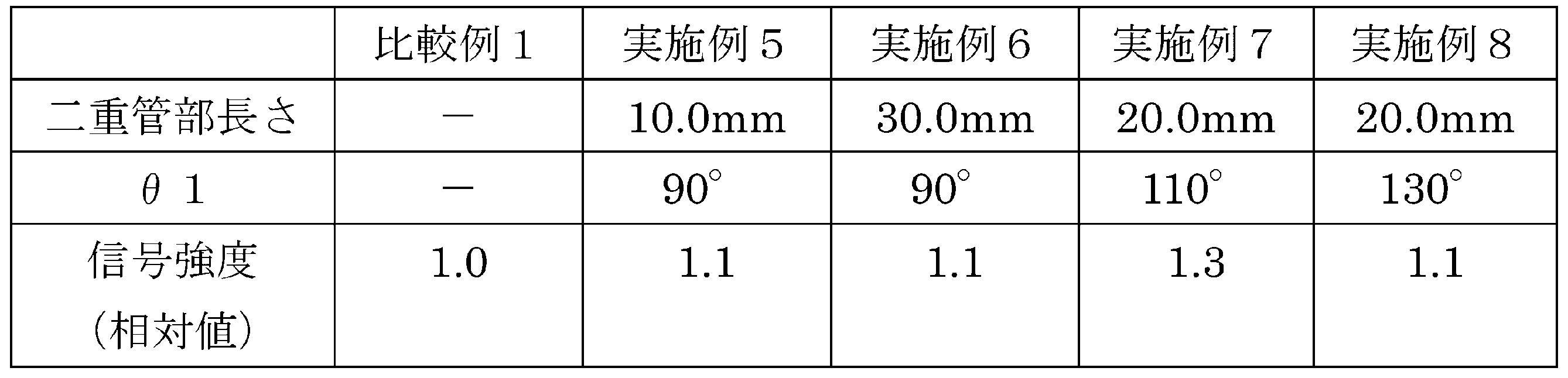
- Example 5 to 8 An ICP-MS was prepared and the sample solution was analyzed in the same manner as in Example 1 except that ⁇ 1 and / or the length of the double tube portion was changed as shown in Table 3.
- the signal intensity (arithmetic average of 10 analyzes) obtained for each example is shown in Table 3 as a relative value to Comparative Example 1 in the same manner as Example 1.
- the signal intensity (relative value) in Examples 5 to 8 is more than 1.0, and the analytical sensitivity (compared to ICP-MS (Comparative Example 1) using a conventional spray chamber) It can be confirmed that the signal strength was improved.
- Example 8 a very small amount of droplet adhesion was confirmed on the wall surface of the conical portion, but such droplet adhesion was not confirmed in Examples 5 to 7.
- Example 9 The ICP-MS of Example 9 was prepared by replacing the commercially available ICP-MS spray chamber with a spray chamber having the mode shown in FIGS. 1 to 3C.
- ⁇ 1 90 °
- ⁇ 2 10 °
- ⁇ 3 30 °
- the maximum inner diameter of the conical portion of the first pipe portion is 50.0 mm
- the length of the conical portion and the maximum inner diameter of the conical portion The ratio (length / maximum inner diameter) is 0.5
- the length of the double pipe portion is 20.0 mm
- the diameter of the additional gas introduction opening and the waste pipe opening of the double pipe portion and the second pipe portion is 3.
- the inner diameter (maximum inner diameter) of the cylindrical part of the first pipe part was 45.0 mm
- the outer diameter of the cylindrical part of the second pipe part was 42.0 mm
- the total length of the spray chamber was 130.0 mm.
- the signal intensity obtained by analyzing the sample solution in the same manner as in Example 1 using the ICP-MS of Example 9 is shown in Table 4 as relative values with respect to Comparative Example 1 as in Example 1.
- the signal intensity variation (relative value to Example 3) was also determined in the same manner as described above.
- the signal intensity obtained by analyzing the sample solution using the ICP-MS of Example 10 in the same manner as in Example 1 is shown in Table 4 as relative values to Comparative Example 1 in the same manner as in Example 1.
- the signal intensity variation (relative value to Example 3) was determined in the same manner as described above.
- the signal intensity obtained by analyzing the sample solution in the same manner as in Example 1 using the ICP-MS in Example 11 is shown in Table 4 as a relative value with respect to Comparative Example 1 as in Example 1.
- the signal intensity variation (relative value to Example 3) was determined in the same manner as described above.
- the signal intensity is more than 1.0, and the analytical sensitivity (compared to ICP-MS (Comparative Example 1) using a conventional spray chamber) ( It can be confirmed that the signal strength was improved. Further, from the comparison between Example 2 and Examples 9 to 11, it was confirmed that the variation in signal intensity was smaller in Examples 9 to 11 than in Example 2. From the above results, if priority is given to further improvement of signal strength, ⁇ 2 is preferably 0 ° to 10 °. If priority is given to both improvement of signal strength and reduction of variation in signal strength, It can be said that ⁇ 2 is preferably in the range of 10 ° to 60 °.
Landscapes
- Chemical & Material Sciences (AREA)
- Analytical Chemistry (AREA)
- Physics & Mathematics (AREA)
- Health & Medical Sciences (AREA)
- Engineering & Computer Science (AREA)
- Plasma & Fusion (AREA)
- Dispersion Chemistry (AREA)
- Life Sciences & Earth Sciences (AREA)
- General Physics & Mathematics (AREA)
- General Health & Medical Sciences (AREA)
- Biochemistry (AREA)
- Immunology (AREA)
- Pathology (AREA)
- Spectroscopy & Molecular Physics (AREA)
- Nuclear Medicine, Radiotherapy & Molecular Imaging (AREA)
- Chemical Kinetics & Catalysis (AREA)
- Electrochemistry (AREA)
- Molecular Biology (AREA)
- Other Investigation Or Analysis Of Materials By Electrical Means (AREA)
- Sampling And Sample Adjustment (AREA)
- Electron Tubes For Measurement (AREA)
- Investigating, Analyzing Materials By Fluorescence Or Luminescence (AREA)
Abstract
Description
ネブライザーにより霧化された試料液滴を含むガス流が導入される試料導入口部と、
上記試料導入口部へ導入された上記ガス流の少なくとも一部を外部へ排出する排出口部と、
一方の端部に上記試料導入口部を有し他方の端部に上記排出口部を有し、上記導入されたガス流の流路となる流路管部と、
を有し、
上記流路管部は、一方の端部に上記排出口部を有する第一管部と、一方の端部に上記試料導入口部を有する第二管部と、を有し、
上記第一管部は、上記排出口部を有する端部とは反対の端部を含む円筒部を有し、かつ上記排出口部の側に向かって内径が小さくなる円錐部を有し、
上記第二管部は、上記試料導入口部を有する端部とは反対の端部を含む円筒部を有し、上記第二管部の円筒部の外径は、上記第一管部の円筒部の内径より小さく、
上記第一管部の円筒部と上記第二管部の円筒部とが少なくとも一部で重なり合うことにより構成された二重管部を有し、
上記二重管部の外側側面に、アディショナルガス導入用開口およびこのアディショナルガス導入用開口を介して上記二重管部内にアディショナルガスを導入する導入路となるアディショナルガス導入管部を有する、スプレーチャンバー、
に関する。
分析対象試料液中の成分を、上記分析装置により分析することを含み、
上記ネブライザーにより霧化された上記試料液の液滴を含むガス流が上記スプレーチャンバーの流路管部に流通される際、上記アディショナルガス導入管部からのアディショナルガスの導入を行うことを更に含む、試料液中の成分分析方法
に関する。
更に本発明の一態様によれば、上記スプレーチャンバーを含む試料霧化導入装置、この試料霧化導入装置を含む分析装置、およびこの分析装置を用いる試料液中の成分分析方法を提供することができる。
本発明の一態様にかかるスプレーチャンバーは、ネブライザーにより霧化された試料液滴を含むガス流が導入される試料導入口部と、上記試料導入口部へ導入された上記ガス流の少なくとも一部を外部へ排出する排出口部と、一方の端部に上記試料導入口部を有し他方の端部に上記排出口部を有し、上記導入されたガス流の流路となる流路管部と、を有する。上記流路管部は、一方の端部に上記排出口部を有する第一管部と、一方の端部に上記試料導入口部を有する第二管部と、を有する。上記第一管部は、上記排出口部を有する端部とは反対の端部を含む円筒部を有し、かつ上記排出口部の側に向かって内径が小さくなる円錐部を有する。上記第二管部は、上記試料導入口部を有する端部とは反対の端部を含む円筒部を有する。ただし上記第二管部の円筒部の外径は、上記第一管部の円筒部の内径より小さい。そして、上記スプレーチャンバーは、上記第一管部の円筒部と上記第二管部の円筒部とが少なくとも一部で重なり合うことにより構成された二重管部を有し、上記二重管部の外側側面に、アディショナルガス導入用開口およびこのアディショナルガス導入用開口を介して上記二重管部内にアディショナルガスを導入する導入路となるアディショナルガス導入管部を有する。
図5は、誘導結合プラズマ分析装置のスプレーチャンバーとして広く用いられているスコット型スプレーチャンバーの一例を示す概略図(側面図)である。
図5に示すスコット型スプレーチャンバー(スコットダブルパススプレーチャンバー)20では、試料液がネブライザー21において霧化されて生成された試料液滴が、キャリアガスとともにガス流として導入される。スコット型スプレーチャンバー20は、スプレーチャンバー全体が二重管構造を有する管状部材であって、試料液滴を含むガス流がネブライザーから二重管の内管22内へ導入される。そしてスプレーチャンバー20内では、液滴の粒径の違いによる液滴の重さの違いを利用して、重力差によって粒径の小さな液滴と粒径の大きな液滴が選別される。粒径の小さな液滴は、二重管の外管23内を経てスプレーチャンバー上方から(図5に示す態様では排出口24から)排出されて分析部に導入される。これに対し、粒径の大きな液滴はスプレーチャンバー内の下方に落下し、図5に示す態様ではスプレーチャンバー下方に設けられた廃液口25からスプレーチャンバー外部へ廃液される。
これに対し本発明の一態様にかかる上記スプレーチャンバーでは、上記二重管部から導入されるアディショナルガスが、試料液滴の壁面付着ロスを低減することに寄与することができる。詳しくは、二重管部に導入されるアディショナルガスが、二重管部から第一管部の円錐部に向かって壁面に沿ってらせん状に旋回するアディショナルガス流をもたらし、このアディショナルガス流が壁面への液滴の付着を抑制するとともに試料液滴を取り込み試料液滴を排出口に導く役割を果たすことにより、試料液滴の壁面付着ロスを低減することができる。
以下、本発明の一態様にかかるスプレーチャンバーについて、更に詳細に説明する。
一方、第二管部12は、第二管部の一方の端部を含む円筒部120と他方の端部を含む試料導入口部121とが連通している。
以上の構造を有する第一管部11と第二管部12とによって、流路管部13が構成されている。更に、第一管部11と第二管部12との接続部において、両管部の円筒部が重なり合って二重管部100が構成されている。二重管部とは、第一管部の円筒部の端部開口と第二管部の円筒部の端部開口との間の部分である。したがって二重管部の両端は開口であるが、開口で囲まれる仮想平面を、以下では底面と呼ぶ。図2Aおよび図2Bに示す態様では、第一管部11と第二管部12とは別部材であって、第一管部11の円筒部112の端部開口に、第二管部12の円筒部120を挿入することにより両管部が接続されて流路管部13が構成されている。例えば、第一管部11の円筒部112が、端部においてテーパー状に先細り端部開口の内径が第二管部12の円筒部120の端部開口の外径と略同一の形状であることにより、両管部を接続して形成される二重管部100に導入されるアディショナルガスが、両管部の接続部から外部に漏出することを抑制することができる。または、シール部材等により接続部の密閉性を確保してもよい。なお接続部の密閉性については、アディショナルガスの漏出を完全に防ぐことは必須ではなく、二重管部に導入されたアディショナルガスがガス流となって流れることを妨げない程度の漏出は許容されるものとする。または、第一管部と第二管部とを一体成形して流路管部を構成してもよい。
一方、Z方向がY方向に対して傾斜している場合、試料導入口部の中心軸方向と略同一の方向から試料液滴を含むガス流をスプレーチャンバー内に導入すると、試料液滴の少なくとも一部が第二管部の円筒部の壁面と衝突し易くなる。第二管部の円筒部の壁面と衝突すると、液滴は衝突粉砕され、より微細な液滴となることができるため、スプレーチャンバーから排出される液滴がより微細化される傾向がある。試料液滴の微細化は、分析装置の分析部における感度の安定性の観点から好ましい。したがって、安定性を重視する場合には、Z方向はY方向に対して傾斜していることが好ましく、例えばθ2は10°~60°の範囲であることが好ましい。
一方、第二管部の試料導入口部は、ネブライザーから試料液滴を含むガス流を導入するための開口を有する限り、その形状および長さは特に限定されるものではない。試料導入口部は、通常、ネブライザー先端を挿入する挿入口部となる。試料導入口部は、例えば円筒形状を有することができるが、上記の通り形状は特に限定されるものではない。
本発明の一態様は、上記スプレーチャンバーおよびネブライザーを含む試料霧化導入装置に関する。
本発明の一態様は、本発明の一態様にかかる試料霧化導入装置および分析部を含む分析装置に関する。
角度θ3は、分析部への試料導入効率と粒径選別能との両観点を考慮すると、20°~90°の範囲であることがより好ましく、20°~70°の範囲であることが更に好ましく、20°~50°の範囲であることが一層好ましく、20°~30°の範囲であることがより一層好ましい。
本発明の一態様は、
分析対象試料液中の成分を、本発明の一態様にかかる分析装置により分析することを含み、
上記ネブライザーにより霧化された上記試料液の液滴を含むガス流が上記スプレーチャンバーの流路管部に流通される際、上記アディショナルガス導入管部からのアディショナルガスの導入を行うことを更に含む、試料液中の成分分析方法、
に関する。以下に、上記成分分析方法について、更に詳細に説明する。
ただし本発明は、シリコン試料の金属不純物汚染評価に限らず、様々な分野における成分分析に適用することができ、適用することにより分析感度の向上を達成することができる。
以下において、スプレーチャンバーのアディショナルガス導入管部にはポリテトラフルオロエチレン製チューブを接続してガスの導入を行い、廃液管部にはポリ塩化ビニル製チューブを接続して廃液を行った。また、以下に記載の実施例のスプレーチャンバーの第一管部および第二管部はガラス製であった。
市販のICP-MSのスプレーチャンバーを、θ1=90°である点を除き図4Aおよび図4Bに示す態様のスプレーチャンバーに変更して実施例1のICP-MSを準備した。実施例1のICP-MSにおいて、θ1=90°、θ2=0°、θ3=30°、第一管部の円錐部の最大内径は45.0mm、円錐部の長さと円錐部の最大内径との比(長さ/最大内径)は0.5、二重管部の長さは20.0mm、アディショナルガス導入用開口ならびに二重管部および第二管部の廃液用開口の直径は3.0mm、第一管部の円筒部の内径(最大内径)は45.0mm、第二管部の円筒部の外径は42.0mm、スプレーチャンバー全長は130.0mmであった。
実施例1のICP-MSにおいて、0.2ppb(体積基準)の115Inを含む0.5規定硝酸水溶液(試料液)の分析を行った。ネブライザーにより試料液をキャリアガス(アルゴンガス;流量0.75L/min)を用いて霧化して試料液滴を含むガス流を生成し、この試料液滴を含むガス流をスプレーチャンバーの試料導入管部からスプレーチャンバーの流路管部へ導入した(試料液滴量(噴霧量):100μL/min)。上記ガス流が流路管部に流通している間、アディショナルガスとしてアルゴンガスを流量約0.4L/minでアディショナルガス導入管部からアディショナルガス導入用開口を介して二重管部へ導入し続けた。分析は10回行い、10回の分析でそれぞれ得られたInイオンの信号強度の算術平均を求めた。
比較のため比較例1として、スプレーチャンバーとして図5に示す態様のスコット型スプレーチャンバー(スコットダブルパススプレーチャンバー)を用いた点以外は実施例1と同様の方法で上記試料液の分析を10回行い、10回の分析でそれぞれ得られたInイオンの信号強度の算術平均を求めた。こうして比較例1で得られたInイオンの信号強度(算術平均)を1.0として、実施例1のICP-MSを用いた分析により得られたInイオンの信号強度(算術平均)を比較例1に対する相対値として求めたところ、表1に示す値であった。
円錐部の長さを変えることにより円錐部の長さと円錐部の最大内径との比(長さ/最大内径)を変えた点以外は実施例1と同様にして、実施例2~4のICP-MSを準備した。実施例2~4のICP-MSを用いて上記と同様に試料液の分析を行い得られた信号強度(算術平均)を比較例1に対する相対値として表1に示す。


一方、表2に示す信号強度のばらつきは、円錐部の長さと最大内径との比(長さ/最大内径)が大きくなるほど小さくなっている。なお実施例1では、円錐部の壁面に微量の液滴付着が確認されたが、そのような液滴付着は実施例2~4では確認されなかった。
分析感度(信号強度)のばらつきが小さいことは、分析結果の信頼性向上の観点から好ましい。分析感度(信号強度)のばらつきをより一層低減する観点からは、円錐部の長さと最大内径との比(長さ/最大内径)は、表2に示す結果に基づき、0.8以上であることが好ましいと言える。
θ1および/または二重管部の長さを表3に示すように変更した点以外、実施例1と同様にICP-MSを準備し試料液の分析を行った。
各実施例について得られた信号強度(10回の分析の算術平均)を、実施例1と同様に比較例1に対する相対値として表3に示す。表3に示すように、実施例5~実施例8において信号強度(相対値)は1.0超であり、従来のスプレーチャンバーを用いたICP-MS(比較例1)と比べて分析感度(信号強度)の向上が可能であったことが確認できる。なお実施例8では、円錐部の壁面に微量の液滴付着が確認されたが、そのような液滴付着は実施例5~7では確認されなかった。
市販のICP-MSのスプレーチャンバーを、図1~図3Cに示す態様のスプレーチャンバーに変更して実施例9のICP-MSを準備した。実施例9のICP-MSにおいて、θ1=90°、θ2=10°、θ3=30°、第一管部の円錐部の最大内径は50.0mm、円錐部の長さと円錐部の最大内径との比(長さ/最大内径)は0.5、二重管部の長さは20.0mm、アディショナルガス導入用開口ならびに二重管部および第二管部の廃液用開口の直径は3.0mm、第一管部の円筒部の内径(最大内径)は45.0mm、第二管部の円筒部の外径は42.0mm、スプレーチャンバー全長は130.0mmであった。
実施例9のICP-MSを用いて実施例1と同様に試料液の分析を行い得られた信号強度を、実施例1と同様に比較例1に対する相対値として表4に示す。
また、実施例9について、上記と同様に信号強度のばらつき(実施例3に対する相対値)も求めた。
θ2=45°とした点以外は実施例9と同様に実施例10のICP-MSを準備した。
実施例10のICP-MSを用いて実施例1と同様に試料液の分析を行い得られた信号強度を、実施例1と同様に比較例1に対する相対値として表4に示す。
また、実施例10について、上記と同様に信号強度のばらつき(実施例3に対する相対値)を求めた。
θ2=60°とした点以外は実施例9と同様に実施例11のICP-MSを準備した。
実施例11のICP-MSを用いて実施例1と同様に試料液の分析を行い得られた信号強度を、実施例1と同様に比較例1に対する相対値として表4に示す。
また、実施例11について、上記と同様に信号強度のばらつき(実施例3に対する相対値)を求めた。
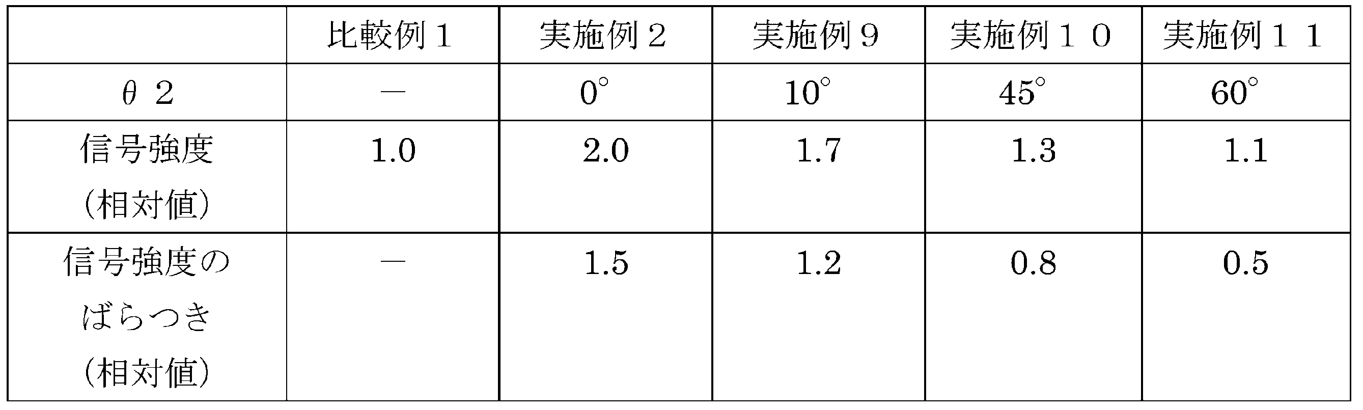
また、実施例2と実施例9~11との対比からは、信号強度のばらつきは実施例9~11が実施例2よりも小さいことが確認された。
以上の結果から、信号強度のより一層の向上を優先するならば、θ2は0°~10°であることが好ましく、信号強度の向上と信号強度のばらつきの低減の両立を優先するならば、θ2は10°~60°の範囲が好ましいと言える。
Claims (17)
- ネブライザーにより霧化された試料液滴を含むガス流が導入される試料導入口部と、
前記試料導入口部へ導入された前記ガス流の少なくとも一部を外部へ排出する排出口部と、
一方の端部に前記試料導入口部を有し他方の端部に前記排出口部を有し、前記導入されたガス流の流路となる流路管部と、
を有し、
前記流路管部は、一方の端部に前記排出口部を有する第一管部と、一方の端部に前記試料導入口部を有する第二管部と、を有し、
前記第一管部は、前記排出口部を有する端部とは反対の端部を含む円筒部を有し、かつ前記排出口部の側に向かって内径が小さくなる円錐部を有し、
前記第二管部は、前記試料導入口部を有する端部とは反対の端部を含む円筒部を有し、前記第二管部の円筒部の外径は、前記第一管部の円筒部の内径より小さく、
前記第一管部の円筒部と前記第二管部の円筒部とが少なくとも一部で重なり合うことにより構成された二重管部を有し、
前記二重管部の外側側面に、アディショナルガス導入用開口および該アディショナルガス導入用開口を介して前記二重管部内にアディショナルガスを導入する導入路となるアディショナルガス導入管部を有する、スプレーチャンバー。 - 前記アディショナルガス導入管部の中心軸方向と、前記第一管部の円筒部の中心軸方向とのなす角度は、90°~130°の範囲である、請求項1に記載のスプレーチャンバー。
- 前記アディショナルガス導入用開口は、前記二重管部の外側側面の第二管部寄りの位置に位置する、請求項1または2に記載のスプレーチャンバー。
- 前記二重管部の長さは、10.0mm~30.0mmの範囲である、請求項1~3のいずれか1項に記載のスプレーチャンバー。
- 前記第一管部の円筒部の内径と前記第二管部の円筒部の外径との差は、1.0mm~6.0mmの範囲である、請求項1~4のいずれか1項に記載のスプレーチャンバー。
- 前記第一管部の円錐部の長さと円錐部の最大内径との比(長さ/最大内径)は、0.5~3.0の範囲である、請求項1~5のいずれか1項に記載のスプレーチャンバー。
- スプレーチャンバーの全長が80.0mm~200.0mmの範囲である、請求項1~6のいずれか1項に記載のスプレーチャンバー。
- 前記試料導入口部の中心軸方向と前記第一管部の円筒部の中心軸方向となす角度は、10°~60°の範囲である、請求項1~7のいずれか1項に記載のスプレーチャンバー。
- 前記試料導入口部の中心軸方向と前記第一管部の円筒部の中心軸方向とは同一方向である、請求項1~7のいずれか1項に記載のスプレーチャンバー。
- 前記第一管部および前記第二管部は、ガラス、石英またはフッ素樹脂製の部材である、請求項1~9のいずれか1項に記載のスプレーチャンバー。
- 前記二重管部の外側側面に、廃液用開口および該廃液用開口を介して前記二重管部内から外部へ廃液する廃液路となる廃液管部を有する、請求項1~10のいずれか1項に記載のスプレーチャンバー。
- スプレーチャンバーおよびネブライザーを含み、
前記スプレーチャンバーは、請求項1~11のいずれか1項に記載のスプレーチャンバーである、試料霧化導入装置。 - 請求項12に記載の試料霧化導入装置および分析部を含む分析装置。
- 前記試料霧化導入装置が設置された設置面の水平方向と、前記スプレーチャンバーの第一管部の円筒部の中心軸方向とがなす角度は、20°~90°の範囲である、請求項13に記載の分析装置。
- 誘導結合プラズマ分析装置であって、前記分析部はプラズマトーチを含む、請求項13または14に記載の分析装置。
- 誘導結合プラズマ質量分析装置である、請求項15に記載の分析装置。
- 分析対象試料液中の成分を、請求項14~16のいずれか1項に記載の分析装置により分析することを含み、
前記ネブライザーにより霧化された前記試料液の液滴を含むガス流が前記スプレーチャンバーの流路管部に流通される際、前記アディショナルガス導入管部からのアディショナルガスの導入を行うことを更に含む、試料液中の成分分析方法。
Priority Applications (5)
| Application Number | Priority Date | Filing Date | Title |
|---|---|---|---|
| KR1020197034069A KR102288662B1 (ko) | 2017-05-12 | 2018-04-24 | 스프레이 챔버, 시료 안개화 도입 장치, 분석 장치 및 시료 중의 성분 분석 방법 |
| CN201880030245.5A CN110603441B (zh) | 2017-05-12 | 2018-04-24 | 喷雾室、试样雾化导入装置、分析装置和试样中的成分分析方法 |
| US16/611,334 US11648574B2 (en) | 2017-05-12 | 2018-04-24 | Spray chamber, sample atomization and introduction device, analysis device, and method of analyzing component in sample |
| JP2019517549A JP6784986B2 (ja) | 2017-05-12 | 2018-04-24 | スプレーチャンバー、試料霧化導入装置、分析装置および試料中の成分分析方法 |
| DE112018002448.2T DE112018002448T5 (de) | 2017-05-12 | 2018-04-24 | Sprühkammer, Probenzerstäubungs- und -einführungsvorrichtung, Analysevorrichtung sowie Verfahren zur Analyse von Bestandteilen einer Probe |
Applications Claiming Priority (2)
| Application Number | Priority Date | Filing Date | Title |
|---|---|---|---|
| JP2017095156 | 2017-05-12 | ||
| JP2017-095156 | 2017-05-12 |
Publications (1)
| Publication Number | Publication Date |
|---|---|
| WO2018207606A1 true WO2018207606A1 (ja) | 2018-11-15 |
Family
ID=64105551
Family Applications (1)
| Application Number | Title | Priority Date | Filing Date |
|---|---|---|---|
| PCT/JP2018/016508 Ceased WO2018207606A1 (ja) | 2017-05-12 | 2018-04-24 | スプレーチャンバー、試料霧化導入装置、分析装置および試料中の成分分析方法 |
Country Status (7)
| Country | Link |
|---|---|
| US (1) | US11648574B2 (ja) |
| JP (1) | JP6784986B2 (ja) |
| KR (1) | KR102288662B1 (ja) |
| CN (1) | CN110603441B (ja) |
| DE (1) | DE112018002448T5 (ja) |
| TW (1) | TWI670752B (ja) |
| WO (1) | WO2018207606A1 (ja) |
Cited By (3)
| Publication number | Priority date | Publication date | Assignee | Title |
|---|---|---|---|---|
| JP2021175968A (ja) * | 2020-04-23 | 2021-11-04 | 株式会社Sumco | 試料導入装置、誘導結合プラズマ分析装置および分析方法 |
| JP7471576B2 (ja) | 2020-04-23 | 2024-04-22 | 株式会社Sumco | 試料導入装置、誘導結合プラズマ分析装置および分析方法 |
| US12068146B2 (en) | 2019-02-04 | 2024-08-20 | Glass Expansion Pty. Limited | Analytic nebuliser |
Families Citing this family (3)
| Publication number | Priority date | Publication date | Assignee | Title |
|---|---|---|---|---|
| DE102021002086B8 (de) * | 2020-04-23 | 2025-12-18 | National Institute Of Advanced Industrial Science And Technology | Probeneinführungsvorrichtung, Analysevorrichtung mit induktiv gekoppeltem Plasma und Analyseverfahren |
| AU2023202154B2 (en) * | 2022-04-08 | 2026-03-05 | Glass Expansion Pty. Limited | A flow control device |
| WO2025133161A1 (en) * | 2023-12-20 | 2025-06-26 | Thermo Fisher Scientific (Bremen) Gmbh | Connecting element for spectrometry |
Citations (4)
| Publication number | Priority date | Publication date | Assignee | Title |
|---|---|---|---|---|
| JPH06102249A (ja) * | 1992-09-22 | 1994-04-15 | Yokogawa Electric Corp | 高周波誘導結合プラズマ質量分析装置 |
| JP2001507449A (ja) * | 1997-01-03 | 2001-06-05 | エムディーエス インコーポレーテッド | 乾燥器付噴霧室 |
| JP2008157895A (ja) * | 2006-12-26 | 2008-07-10 | Horiba Ltd | 試料導入装置 |
| US20130181126A1 (en) * | 2011-10-26 | 2013-07-18 | Dvs Sciences Inc. | Sample Transferring Apparatus for Mass Cytometry |
Family Cites Families (19)
| Publication number | Priority date | Publication date | Assignee | Title |
|---|---|---|---|---|
| US4926021A (en) | 1988-09-09 | 1990-05-15 | Amax Inc. | Reactive gas sample introduction system for an inductively coupled plasma mass spectrometer |
| JP2852838B2 (ja) * | 1992-09-10 | 1999-02-03 | セイコーインスツルメンツ株式会社 | 誘導結合プラズマ質量分析装置 |
| JPH09159610A (ja) | 1995-12-07 | 1997-06-20 | Jeol Ltd | 試料導入安定化機構を備えたプラズマ分析装置 |
| US5969352A (en) * | 1997-01-03 | 1999-10-19 | Mds Inc. | Spray chamber with dryer |
| JPH11326165A (ja) | 1998-05-18 | 1999-11-26 | Yokogawa Analytical Systems Inc | 試料液の霧化導入装置 |
| US6177669B1 (en) * | 1998-09-28 | 2001-01-23 | Varian, Inc. | Vortex gas flow interface for electrospray mass spectrometry |
| GB9911336D0 (en) | 1999-05-15 | 1999-07-14 | Graseby Dynamics Ltd | Separation and collection of analyte materials |
| JP4112780B2 (ja) | 2000-05-31 | 2008-07-02 | 株式会社島津製作所 | 液体クロマトグラフ質量分析装置 |
| JP2001357815A (ja) | 2000-06-16 | 2001-12-26 | Jeol Ltd | ネブライザー |
| CN2619257Y (zh) | 2003-06-03 | 2004-06-02 | 西安索坤技术开发有限公司 | 双层多头火焰燃烧器 |
| JP4491607B2 (ja) | 2005-03-03 | 2010-06-30 | 国立大学法人 千葉大学 | 全量導入型ネブライザー対応シースガス導入型スプレーチャンバー |
| US7981365B2 (en) | 2005-09-15 | 2011-07-19 | The United States Of America As Represented By The Secretary Of The Navy | Electrospray coating of aerosols for labeling and identification |
| US9186607B1 (en) * | 2010-09-21 | 2015-11-17 | Elemental Scientific, Inc. | Dual spray chamber |
| JP5965743B2 (ja) * | 2012-06-27 | 2016-08-10 | 株式会社日立ハイテクサイエンス | Icp装置及び分光分析装置並びに質量分析装置 |
| GB201216412D0 (en) * | 2012-09-14 | 2012-10-31 | Shimadzu Corp | Apparatus for providing gaseous sample ions/molecules and a corresponding method |
| JP6213775B2 (ja) * | 2014-01-21 | 2017-10-18 | 国立研究開発法人産業技術総合研究所 | 噴霧器および分析装置 |
| CN204429018U (zh) | 2015-02-05 | 2015-07-01 | 中牛集团有限公司 | 喷浆干燥机尾气处理装置 |
| CN105929012B (zh) * | 2016-04-13 | 2018-11-09 | 中国科学院生态环境研究中心 | 雾化室、采用其的进样系统和icp-ms |
| US10147592B2 (en) * | 2016-05-18 | 2018-12-04 | Perkinelmer Health Sciences Canada, Inc. | Spray chambers and methods of using them |
-
2018
- 2018-04-24 KR KR1020197034069A patent/KR102288662B1/ko active Active
- 2018-04-24 CN CN201880030245.5A patent/CN110603441B/zh active Active
- 2018-04-24 US US16/611,334 patent/US11648574B2/en active Active
- 2018-04-24 WO PCT/JP2018/016508 patent/WO2018207606A1/ja not_active Ceased
- 2018-04-24 JP JP2019517549A patent/JP6784986B2/ja active Active
- 2018-04-24 DE DE112018002448.2T patent/DE112018002448T5/de active Granted
- 2018-05-09 TW TW107115728A patent/TWI670752B/zh active
Patent Citations (4)
| Publication number | Priority date | Publication date | Assignee | Title |
|---|---|---|---|---|
| JPH06102249A (ja) * | 1992-09-22 | 1994-04-15 | Yokogawa Electric Corp | 高周波誘導結合プラズマ質量分析装置 |
| JP2001507449A (ja) * | 1997-01-03 | 2001-06-05 | エムディーエス インコーポレーテッド | 乾燥器付噴霧室 |
| JP2008157895A (ja) * | 2006-12-26 | 2008-07-10 | Horiba Ltd | 試料導入装置 |
| US20130181126A1 (en) * | 2011-10-26 | 2013-07-18 | Dvs Sciences Inc. | Sample Transferring Apparatus for Mass Cytometry |
Cited By (4)
| Publication number | Priority date | Publication date | Assignee | Title |
|---|---|---|---|---|
| US12068146B2 (en) | 2019-02-04 | 2024-08-20 | Glass Expansion Pty. Limited | Analytic nebuliser |
| JP2021175968A (ja) * | 2020-04-23 | 2021-11-04 | 株式会社Sumco | 試料導入装置、誘導結合プラズマ分析装置および分析方法 |
| JP7471576B2 (ja) | 2020-04-23 | 2024-04-22 | 株式会社Sumco | 試料導入装置、誘導結合プラズマ分析装置および分析方法 |
| JP7471575B2 (ja) | 2020-04-23 | 2024-04-22 | 株式会社Sumco | 試料導入装置、誘導結合プラズマ分析装置および分析方法 |
Also Published As
| Publication number | Publication date |
|---|---|
| DE112018002448T5 (de) | 2020-02-20 |
| JP6784986B2 (ja) | 2020-11-18 |
| US20200078806A1 (en) | 2020-03-12 |
| US11648574B2 (en) | 2023-05-16 |
| JPWO2018207606A1 (ja) | 2020-03-12 |
| TW201901740A (zh) | 2019-01-01 |
| TWI670752B (zh) | 2019-09-01 |
| KR102288662B1 (ko) | 2021-08-10 |
| CN110603441B (zh) | 2022-06-03 |
| CN110603441A (zh) | 2019-12-20 |
| KR20190139290A (ko) | 2019-12-17 |
Similar Documents
| Publication | Publication Date | Title |
|---|---|---|
| JP6784986B2 (ja) | スプレーチャンバー、試料霧化導入装置、分析装置および試料中の成分分析方法 | |
| JP7471576B2 (ja) | 試料導入装置、誘導結合プラズマ分析装置および分析方法 | |
| JP2021175968A (ja) | 試料導入装置、誘導結合プラズマ分析装置および分析方法 | |
| JP5240806B2 (ja) | プラズマを用いて試料をイオン化もしくは原子化して分析を行う分析装置用の噴霧器および分析装置 | |
| US9520278B2 (en) | Nebulizer and analyzer | |
| CN107209124B (zh) | 在线移送的分析样品的分析系统 | |
| CN111266140B (zh) | 无油分选-直接注入-icpms单细胞分析系统 | |
| US5477048A (en) | Inductively coupled plasma mass spectrometer | |
| US9127982B2 (en) | Spark chamber for optical emission analysis | |
| DE102017205545A1 (de) | Probezerstäuber mit einstellbarer leitung und verwandte verfahren | |
| CN105929012B (zh) | 雾化室、采用其的进样系统和icp-ms | |
| US20050230617A1 (en) | Demountable direct injection high efficiency nebulizer for inductively coupled plasma mass spectrometry | |
| US11579092B2 (en) | Sample introduction device, inductively coupled plasma analyzing device and analyzing method | |
| JP2008275372A (ja) | プラズマ分析装置及びプラズマ分析方法 | |
| US12488973B2 (en) | Flow control device | |
| Linge | GGR Handbook of Rock and Mineral Analysis Chapter 5 The Inductively Coupled Plasma | |
| JP2024080785A (ja) | スプレーチャンバー | |
| CN118311128B (zh) | 一种紫外光辅助电喷雾装置及方法 | |
| US11630039B1 (en) | Spray chamber having dual input ports for impingement gas and sensitivity enhancement gas addition | |
| CN115575203A (zh) | 液态样品的检测系统和方法 | |
| McCleary | Sample introduction and solvent effects in an argon and helium microwave induced plasma |
Legal Events
| Date | Code | Title | Description |
|---|---|---|---|
| 121 | Ep: the epo has been informed by wipo that ep was designated in this application |
Ref document number: 18797717 Country of ref document: EP Kind code of ref document: A1 |
|
| ENP | Entry into the national phase |
Ref document number: 2019517549 Country of ref document: JP Kind code of ref document: A |
|
| ENP | Entry into the national phase |
Ref document number: 20197034069 Country of ref document: KR Kind code of ref document: A |
|
| 122 | Ep: pct application non-entry in european phase |
Ref document number: 18797717 Country of ref document: EP Kind code of ref document: A1 |