WO2018207563A1 - 光反射フィルム及び光反射フィルムの製造方法 - Google Patents
光反射フィルム及び光反射フィルムの製造方法 Download PDFInfo
- Publication number
- WO2018207563A1 WO2018207563A1 PCT/JP2018/015888 JP2018015888W WO2018207563A1 WO 2018207563 A1 WO2018207563 A1 WO 2018207563A1 JP 2018015888 W JP2018015888 W JP 2018015888W WO 2018207563 A1 WO2018207563 A1 WO 2018207563A1
- Authority
- WO
- WIPO (PCT)
- Prior art keywords
- film
- layer
- refractive index
- light reflecting
- unit
- Prior art date
- Legal status (The legal status is an assumption and is not a legal conclusion. Google has not performed a legal analysis and makes no representation as to the accuracy of the status listed.)
- Ceased
Links
Images



Classifications
-
- B—PERFORMING OPERATIONS; TRANSPORTING
- B32—LAYERED PRODUCTS
- B32B—LAYERED PRODUCTS, i.e. PRODUCTS BUILT-UP OF STRATA OF FLAT OR NON-FLAT, e.g. CELLULAR OR HONEYCOMB, FORM
- B32B7/00—Layered products characterised by the relation between layers; Layered products characterised by the relative orientation of features between layers, or by the relative values of a measurable parameter between layers, i.e. products comprising layers having different physical, chemical or physicochemical properties; Layered products characterised by the interconnection of layers
- B32B7/02—Physical, chemical or physicochemical properties
-
- C—CHEMISTRY; METALLURGY
- C09—DYES; PAINTS; POLISHES; NATURAL RESINS; ADHESIVES; COMPOSITIONS NOT OTHERWISE PROVIDED FOR; APPLICATIONS OF MATERIALS NOT OTHERWISE PROVIDED FOR
- C09J—ADHESIVES; NON-MECHANICAL ASPECTS OF ADHESIVE PROCESSES IN GENERAL; ADHESIVE PROCESSES NOT PROVIDED FOR ELSEWHERE; USE OF MATERIALS AS ADHESIVES
- C09J201/00—Adhesives based on unspecified macromolecular compounds
-
- G—PHYSICS
- G02—OPTICS
- G02B—OPTICAL ELEMENTS, SYSTEMS OR APPARATUS
- G02B5/00—Optical elements other than lenses
- G02B5/08—Mirrors
Definitions
- the present invention relates to a light reflecting film and a method for producing the light reflecting film, and more particularly to a light reflecting film excellent in flatness, adhesion and light reflecting property and excellent in durability, and a method for producing the same.
- Such a light reflecting film is manufactured by applying and laminating a coating solution containing a mixture of a water-soluble polymer and metal oxide fine particles by a wet coating method as a technique using a liquid phase film forming method.
- a light reflecting film near infrared reflecting film
- a coating liquid containing zirconium oxide is prepared as a high refractive index layer coating liquid
- a coating liquid containing a low refractive index oxide such as silicon oxide is prepared as a low refractive index layer coating liquid.
- a method for forming a laminated film by alternately applying multiple layers is described, whereby it can be manufactured by an inexpensive method and a high-quality light reflecting film can be obtained.
- Patent Document 2 discloses a gas barrier layer having the same configuration in the field of gas barrier films having a gas barrier layer having a multilayer structure. There is disclosed a gas barrier film having a structure in which two films having the respective gas barrier layers are arranged to face each other and adhered and laminated through an adhesive layer. By adopting this configuration, it is said that problems due to the occurrence of curling can be prevented and damage to the gas barrier layer can be prevented.
- Patent Document 2 is directed to a gas barrier film, which is different in application field from a light reflecting film, and the gas barrier layer in contact with the adhesive layer has a single layer structure, and includes a plurality of layers. There is no disclosure about the problems related to the laminated body in which the layers are laminated.
- Patent Document 3 discloses a multilayer film having a configuration in which two laminates in which a thermoplastic resin layer and an adhesive resin layer are alternately laminated between an outer layer and an inner layer are laminated via an adhesive layer. Proposed. With such a configuration, it is said that curling can be prevented.
- the method described in Patent Document 3 is used for skin pack packaging, and the field of application is clearly different from the light reflective film targeted by the present invention, and regarding problems and the like in the configuration in which the optical reflective layer is laminated, No mention is made.
- the present invention has been made in view of the above-described problems and circumstances, and the solution to the problem is to provide a light reflecting film excellent in flatness, adhesion and light reflectivity and excellent in durability, and a method for producing the same. It is to be.
- the present inventor has two or more reflective layer units in which two or more layers having different refractive indexes are laminated.
- a reflective layer unit group having an adhesive layer between the two or more reflective layer units, the layer thickness of the adhesive layer being within a specific range, and comprising the two or more reflective layer units and the adhesive layer
- the present invention has found that the light reflecting film sandwiched between the pair of substrate films can realize a light reflecting film having excellent flatness, adhesion and light reflecting property and excellent durability. It came to.
- a light reflecting film having a pair of base film and two or more reflecting layer units in which two or more layers having different refractive indexes are laminated, An adhesive layer is provided between the two or more reflective layer units, and the thickness of the adhesive layer is in the range of 0.1 to 1.0 ⁇ m; And the reflection layer unit group comprised by the said 2 or more reflection layer unit and an adhesive layer is pinched
- the light reflection film characterized by the above-mentioned.
- each reflective layer unit 2 In the configuration having two or more reflective layer units, when the number of layers of one reflective layer unit facing each other with the adhesive layer interposed therebetween is L1, and the number of layers of the other reflective layer unit is L2, each reflective layer unit 2.
- One of said pair of base film is a transfer film which can be peeled, The light reflection film of Claim 1 or 2 characterized by the above-mentioned.
- Item 4 The light reflection according to any one of Items 1 to 3, wherein the content of the inorganic fine particles in the adhesive layer is in the range of 0 to 20% by volume with respect to the total volume of the adhesive layer. the film.
- one film unit has a transfer film that can be peeled off as a base film, and after peeling off the transfer film, the film unit is pasted on the other film unit via an adhesive layer. 6.
- the inventors of the present invention are not a method of forming a reflection layer group in which two or more layers having different refractive indexes are laminated by a single coating, but a plurality of layers with a number of layers smaller than a desired number of layers. It has been found that the above problems can be solved by forming a reflection unit and bonding them through an adhesive layer having a thin layer thickness, and the present invention has been completed.
- Reflecting layer units formed with a small number of layers are not curled themselves and therefore do not cause handling or peeling.
- the two reflective layer units interfere with each other, are sharp (having a narrow half-value width), and exhibit high reflectivity. Found out to be. It was also found that by regulating the inorganic fine particle concentration in the adhesive layer to 20% by volume or less, the stress of the reflective layer unit group is relaxed, and the adhesion and durability are further improved.
- FIG. 5A is a schematic cross-sectional view of a first film unit used in manufacturing the light reflecting film shown in FIG. 5A.
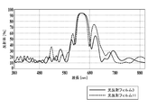
- Schematic sectional view of the second film unit used in the production of the light reflecting film shown in FIG. 5A The graph which shows an example of the reflection spectrum of the light reflection film of this invention.
- the light reflection film of the present invention is a light reflection film having a pair of base film and two or more reflection layer units in which two or more layers having different refractive indexes are laminated, and the two or more reflection layers A reflective layer unit group having an adhesive layer between the units, the thickness of the adhesive layer being in the range of 0.1 to 1.0 ⁇ m, and comprising the two or more reflective layer units and the adhesive layer; And being sandwiched between the pair of substrate films.
- the layer of one of the reflecting layer units facing each other with the adhesive layer interposed therebetween when the number is L1 and the number of layers of the other reflection layer unit is L2, the ratio L1 / L2 of the number of layers of each reflection layer unit is within the range of 0.5 to 1.5. This is preferable in that excellent reflection characteristics can be obtained.
- one of the pair of substrate films is a peelable transfer film because the film thickness of the entire light reflecting film can be reduced.
- the adhesive layer contains inorganic fine particles in the range of 0 to 20% by volume when the total volume of the adhesive layer is 100% by volume, from the viewpoint of improving stress relaxation and durability of the reflective layer unit. preferable.
- the manufacturing method of the light reflection film of this invention has the process of using two or more film units which have a reflection layer unit on a base film, and bonding two reflection layer units through an adhesive layer. It is characterized by.
- one film unit has a transfer film that can be peeled as a base film, and after peeling the transfer film, the other film unit is interposed via an adhesive layer. It is a preferred embodiment in that the step of bonding with can efficiently produce a light reflecting film having a configuration having three or more reflective layer units via a plurality of adhesive layers.
- ⁇ representing a numerical range is used in the sense that numerical values described before and after the numerical value range are included as a lower limit value and an upper limit value.
- the light reflecting film of the present invention has a pair of base films and two or more reflecting layer units in which two or more layers having different refractive indexes are laminated, and an adhesive layer between the two or more reflecting layer units.
- a reflective layer unit group comprising the two or more reflective layer units and the adhesive layer, wherein the thickness of the adhesive layer is in the range of 0.1 to 1.0 ⁇ m. It is the structure clamped with the material film, It is characterized by the above-mentioned.
- FIG. 1 is a schematic cross-sectional view showing a first example of the configuration of the light reflecting film of the present invention.
- the first example of the light reflecting film (1) of the present invention is in a position in contact with the base film 1 (2A, for example, a transparent resin film of polyethylene terephthalate (abbreviation: PET)).
- a first reflective layer unit (3A) is formed. This is referred to as a first film unit (F1).
- the first reflective layer unit (3A) is configured by stacking two or more layers having different refractive indexes. Specifically, a high refractive index layer and a low refractive index layer are alternately stacked. It is a laminate.
- the second reflective layer unit (3B) is also formed on the base film 2 (2B) which is the other of the pair of base films. This is referred to as a second film unit (F2).
- the reflective film (1) is constituted.
- the two or more reflection layer units in which two or more layers having different refractive indexes are laminated may be the same or different reflection layer units.
- a laminate formed by laminating two or more layers having different refractive indexes is referred to as a “reflective layer unit”, and is constituted by two or more reflective layer units and an adhesive layer provided therebetween. This is referred to as a “reflective layer unit group”.
- the reflective layer unit according to the present invention is preferably a laminate in which high refractive index layers and low refractive index layers are alternately laminated, but it is a “high refractive index layer” and “low refractive index layer”.
- This term means that when the difference in refractive index between two adjacent layers is compared, the higher refractive index layer is the higher refractive index layer and the lower refractive index layer is the low refractive index layer.
- the terms “high refractive index layer” and “low refractive index layer” are the same when each refractive index layer constituting the light reflecting film is focused on two adjacent refractive index layers. All forms other than those having a refractive index are included.
- FIG. 2 is a schematic cross-sectional view showing a configuration in which an adhesive layer is provided on three reflective layer units and each reflective interlayer unit in the second example of the configuration of the light reflecting film of the present invention.
- the first reflective layer unit (3A), the adhesive layer 1 (AL1), and the second reflective layer unit (3B) are interposed between the pair of base film 1 (2A) and base film 2 (2B).
- the adhesive layer 2 (AL2) and the third reflective layer unit (3C) are arranged.
- the ratio L1 / L2 of the number of layers of the reflective layer unit is in the range of 0.5 to 1.5.
- the reflective layer units at positions facing each other with the adhesive layer interposed therebetween are the first reflective layer unit (3A) and the second reflective layer unit (3B) disposed with the adhesive layer 1 (AL1) interposed therebetween.
- L1 / L2 is in the range of 0.5 to 1.5.
- the layers are arranged with the adhesive layer 2 (AL2) interposed therebetween.
- L2 and L3 0.5 to 1.5. preferable.
- FIG. 3 is a schematic sectional view showing a third example of the configuration of the light reflecting film according to the present invention, in which one of a pair of substrate films is a peelable transfer film.
- the light reflecting film shown in FIG. 3 is effective for the production of the second example of the structure of the light reflecting film of the present invention.
- the laminated body shown in FIG. 3 can be effectively used as an intermediate for producing the light reflecting film shown in FIG. 2, for example.
- the laminate (1A) having the configuration shown in FIG. 3 is similar to the configuration described in FIG. 1, but when the light reflecting film having the configuration shown in FIG. 2 is produced, the laminate (1A) is formed on the base film 2 (2B).
- FIG. 4 is a schematic view showing process steps for producing the light reflecting film having the configuration of the second example shown in FIG. 2 using the laminate shown in FIG.
- Step A the third reflective layer unit (3C) is formed on the base film 2 (2B).
- Step B the adhesive layer 2 (AL2) is formed on the third reflective layer unit (3C).
- Step C the second reflective layer unit (3B) is formed on the transfer film (5), and the adhesive layer 2 (AL2) and the second reflective layer unit (3B) are arranged to face each other.
- Step D the adhesive layer 2 (AL2) and the second reflective layer unit (3B) are bonded together by the method described in FIG. 5A to be described later to produce a laminate (1A).
- Step E the transfer film (5) is peeled from the laminate (1A) to form the second film unit (F2).
- Step F the adhesive layer 1 (AL1) is formed on the second reflective layer unit (3B).
- step G the second film unit (F2) and the first film unit (F1) in which the first reflective layer unit (3A) is formed on the base film 1 (2A) will be described later with reference to FIG. 5A. Is bonded via the adhesive layer (AL1).
- Step H the light reflecting film (1) having the configuration shown in FIG.
- the light reflecting film having the transfer film shown in FIG. 3 can also be used as a single light reflecting film.
- the light reflecting film is provided with the transfer film (5).
- the transfer film (5) prevents damage such as scratches on each reflection layer unit and is used as a light reflection film, for example, the transfer film (5) is peeled off to form a light reflection film with a thinner film. As a result, it is possible to improve the curved surface followability of the vehicle glass having a curved surface or the like, which is preferable.
- the base film used for the light reflecting film of the present invention is not particularly limited as long as it is formed of a transparent organic material.
- Examples of materials applicable to the base film according to the present invention include methacrylate ester, polyethylene terephthalate (abbreviation: PET), polyethylene naphthalate (abbreviation: PEN), polycarbonate (abbreviation: PC), polyarylate, polystyrene ( Abbreviations: PS), films made of resins such as aromatic polyamide, polyether ether ketone, polysulfone, polyether sulfone, polyimide, polyetherimide, and hybrid resin films obtained by laminating two or more layers of the above resins. It is done.
- polyethylene terephthalate (abbreviation: PET), polyethylene naphthalate (abbreviation: PEN), polycarbonate (abbreviation: PC), and the like are preferably used.
- the thickness of the base film is preferably in the range of 5 to 200 ⁇ m, more preferably in the range of 15 to 150 ⁇ m.
- Two or more base films may be stacked, and in this case, the types of base films may be the same or different.
- the substrate film preferably has a transmittance in the visible light region represented by JIS R 3106: 1998 of 85% or more, particularly preferably 90% or more. It is advantageous and preferable in that the transmittance of the visible light region shown in JIS R 3106: 1998 can be 50% or more when the base film is equal to or higher than the above-described transmittance.
- the base film using the above resin or the like may be an unstretched film or a stretched film.
- a stretched film is preferable from the viewpoint of improving strength and suppressing thermal expansion.
- the base film can be manufactured by a conventionally known general film forming method.
- an unstretched base film that is substantially amorphous and not oriented can be produced by melting a resin as a material with an extruder, extruding it with an annular die or a T-die, and quenching.
- the unstretched substrate is uniaxially stretched, tenter-type sequential biaxial stretching, tenter-type simultaneous biaxial stretching, tubular-type simultaneous biaxial stretching, and other known methods, such as the substrate flow (vertical axis) direction, or
- a stretched substrate film can be produced by stretching in the direction perpendicular to the flow direction of the substrate (horizontal axis).
- the draw ratio in this case can be appropriately selected according to the resin as the raw material of the base film, but is preferably 2 to 10 times in the vertical axis direction and the horizontal axis direction.
- the base film may be subjected to relaxation treatment or offline heat treatment in terms of dimensional stability.
- the relaxation treatment is performed in a process from the heat setting in the stretching process of the polyester film to the winding in the transversely stretched tenter or after exiting the tenter.
- the relaxation treatment is preferably performed at a treatment temperature in the range of 80 to 200 ° C., more preferably the treatment temperature is in the range of 100 to 180 ° C.
- the relaxation rate is preferably in the range of 0.1 to 10% in both the longitudinal direction and the width direction, and more preferably, the relaxation rate is in the range of 2 to 6%.
- the relaxed base film is subjected to off-line heat treatment to improve heat resistance and to improve dimensional stability.
- the base film is preferably coated with the undercoat layer coating solution in-line on one or both sides during the film formation process.
- undercoating during the film forming process is referred to as in-line undercoating.
- resins used in the undercoat layer coating solution useful in the present invention include polyester resins, acrylic-modified polyester resins, polyurethane resins, acrylic resins, vinyl resins, vinylidene chloride resins, polyethyleneimine vinylidene resins, polyethyleneimine resins, and polyvinyl alcohol resins. , Modified polyvinyl alcohol resin, gelatin and the like, and any of them can be preferably used.
- a conventionally well-known additive can also be added to these undercoat layers.
- the undercoat layer can be coated by a known method such as roll coating, gravure coating, knife coating, dip coating or spray coating.
- the coating amount of the undercoat layer is preferably about 0.01 to 2 g / m 2 (dry state).
- ⁇ Transfer film> it is a preferable form to comprise one of a pair of base film with the transfer film which can be peeled.
- the transfer film is composed of a base film applicable to the present invention described above, for example, a resin such as polyethylene terephthalate (abbreviation: PET), polyethylene naphthalate (abbreviation: PEN), polycarbonate (abbreviation: PC), or the like.
- the base film is a film in which a release layer having a release agent is formed on the side in contact with the reflective layer unit.
- the release agent include silicone resins, long-chain alkyl resins, fluorine resins, and fluorosilicones. Examples thereof include alkyd resins such as resins, long-chain alkyl-modified alkyd resins, and silicone-modified alkyd resins, and preferably a release agent composed of a silicone resin.
- Silicone contained in the release agent is monofunctional silicone (constituent unit having three organic substituents), bifunctional silicone (constituent unit having two organic substituents), trifunctional silicone (1 organic substituent is 1). And a tetrafunctional silicone (a structural unit having no organic substituent).
- the light reflecting film of the present invention is characterized by having two or more reflecting layer units in which two or more layers having different refractive indexes are laminated via an adhesive layer.
- the reflective layer unit is formed by laminating two or more layers having different refractive indexes, and specifically, is a laminated body in which high refractive index layers and low refractive index layers are alternately laminated.
- the two or more reflection layer units in which two or more layers having different refractive indexes are laminated may be the same or different reflection layer units.
- the low refractive index layer constituting the reflective layer unit is mainly composed of the first metal oxide particles and the first binder resin
- the high refractive index layer is mainly composed of the second metal oxide particles and the first metal oxide particles. 2 binder resins.
- the low refractive index layer contains a first binder resin
- the high refractive index layer contains a second binder resin.
- the binder resin which is a material for forming each refractive index layer it is preferable to use a water-soluble binder resin, for example, a polyvinyl alcohol-based resin as a coating film forming material.
- Wet coating method for example, gravure printing method, flexographic printing method, screen printing method, roll coating method, bar coating method, dip coating method, spin coating method, casting method, die coating method, blade coating method, bar coating method, Lamination can be performed using a gravure coating method, a curtain coating method, a spray coating method, a doctor coating method, an ink jet method, or the like.
- wet coating methods have a wide range of options because the coating device used is simple and the heat resistance of the base film is not questioned, and in particular, this is a coating film forming method that is effective when a resin film is used as the base film. .
- a wet coating method by applying a wet coating method, a mass production method such as a roll-to-roll method can be adopted, which is advantageous in terms of cost and process time.
- each refractive index layer containing a binder resin is highly flexible, there is an advantage that defects are not easily generated even when it is wound in a roll shape during production or transportation, and the handling property is excellent.
- ⁇ Binder resin of low refractive index layer A conventionally known binder resin can be applied to the low refractive index layer according to the present invention.
- the low refractive index layer it is particularly preferable to apply a polyvinyl alcohol resin as a binder resin.
- the polyvinyl alcohol obtained by hydrolyzing vinyl acetate preferably has an average degree of polymerization of 1000 or more, and particularly preferably has an average degree of polymerization in the range of 1500 to 5000.
- the degree of saponification is preferably in the range of 70 to 100%, particularly preferably in the range of 80 to 99.9%.
- the polyvinyl alcohol used in the present invention may be a synthetic product or a commercially available product.
- Examples of commercially available products used as polyvinyl alcohol include, for example, PVA-102, PVA-103, PVA-105, PVA-110, PVA-117, PVA-120, PVA-124, PVA-203, PVA-205, PVA-210, PVA-217, PVA-220, PVA-224, PVA-235 (above, manufactured by Kuraray Co., Ltd.), JC-25, JC-33, JF-03, JF-04, JF-05, JP- 03, JP-04, JP-05, JP-45 (above, manufactured by Nippon Vinegar Poval Co., Ltd.) and the like.
- the binder resin according to the present invention may contain modified polyvinyl alcohol partially modified in addition to normal polyvinyl alcohol obtained by hydrolyzing polyvinyl acetate within a range not impairing the effects of the present invention.
- modified polyvinyl alcohol When such a modified polyvinyl alcohol is included, the adhesion, water resistance, and flexibility of the film may be improved.
- modified polyvinyl alcohol examples include cation-modified polyvinyl alcohol, anion-modified polyvinyl alcohol, nonion-modified polyvinyl alcohol, and vinyl alcohol polymers.
- vinyl acetate resin for example, “Exeval” (trade name) manufactured by Kuraray Co., Ltd.
- polyvinyl acetal resin obtained by reacting polyvinyl alcohol with aldehyde (for example, “S-LEC” manufactured by Sekisui Chemical Co., Ltd.
- silanol-modified polyvinyl alcohol having a silanol group for example, “R-1130” (trade name) manufactured by Kuraray Co., Ltd.
- modified polyvinyl alcohol resin having an acetoacetyl group in the molecule for example, Nippon Synthetic Chemical Industry
- "Gosefimer (registered trademark) Z / WR series” (trade name) manufactured by Co., Ltd.) and the like are also included in the polyvinyl alcohol resin.
- Anion-modified polyvinyl alcohol is described in, for example, polyvinyl alcohol having an anionic group described in JP-A-1-206088, JP-A-61-237681 and JP-A-63-307979.
- examples thereof include a copolymer of vinyl alcohol and a vinyl compound having a water-soluble group, and modified polyvinyl alcohol having a water-soluble group described in JP-A-7-285265.
- Nonionic modified polyvinyl alcohols include, for example, polyvinyl alcohol derivatives obtained by adding a polyalkylene oxide group described in JP-A-7-9758 to a part of vinyl alcohol, and described in JP-A-8-25795. Block copolymer of vinyl compound having hydrophobic group and vinyl alcohol, silanol-modified polyvinyl alcohol having silanol group, reactive group-modified polyvinyl alcohol having reactive group such as acetoacetyl group, carbonyl group and carboxy group Etc.
- cation-modified polyvinyl alcohol for example, primary to tertiary amino groups and quaternary ammonium groups described in JP-A No. 61-10383 are contained in the main chain or side chain of the polyvinyl alcohol. It is obtained by saponifying a copolymer of an ethylenically unsaturated monomer having a cationic group and vinyl acetate.
- vinyl alcohol polymer examples include EXEVAL (trade name: manufactured by Kuraray Co., Ltd.) and Nichigo G polymer (trade name: manufactured by Nippon Synthetic Chemical Industry Co., Ltd.).
- the low refractive index layer in addition to the above-described water-soluble polyester resin and polyvinyl alcohol-based resin, other binder resins can be applied as long as the object and effects of the present invention are not impaired.
- Binder resin of high refractive index layer As the binder resin applicable to the high refractive index layer, it is particularly preferable to apply the same polyvinyl alcohol-based resin as described in the low refractive index layer from the viewpoint of good film formability.
- Polycarbonate, poly (meth) acrylate and the like can be used.
- the binder resin constituting the high refractive index layer may be one type or two or more types.
- Poly (meth) acrylate is a polymer of acrylic acid ester or methacrylic acid ester, and examples thereof include polymethyl methacrylate and polyethyl methacrylate.
- the weight average molecular weight of the polycarbonate and poly (meth) acrylate contained in the high refractive index layer is about 10,000 to 1,000,000, and preferably in the range of 50,000 to 800,000.
- the value measured by gel permeation chromatography (GPC) is employ
- water-soluble binder resins applicable to the low refractive index layer and the high refractive index layer according to the present invention include gelatin, celluloses, thickening polysaccharides, and polymers having reactive functional groups.
- examples of other water-soluble binder resins applicable to the low refractive index layer and the high refractive index layer according to the present invention include gelatin, celluloses, thickening polysaccharides, and polymers having reactive functional groups.
- JP, 2012-242644, JP, 2012-252137, JP, 2013-4916, JP, 2013-97248, JP, 2013-148849, JP, 2014-89347 JP Reference can be made to the descriptions in Japanese Unexamined Patent Application Publication Nos. 2014-201450 and 2014-215513. Kill.
- the low refractive index layer and the high refractive index layer preferably contain metal oxide particles.
- silicon oxide (silicon dioxide) is used as the metal oxide particles in the low refractive index layer.
- silicon oxide include synthetic amorphous silica, colloidal silica, zinc oxide, alumina, colloidal alumina, and the like.
- colloidal silica sol, particularly acidic colloidal silica sol is more preferably used, and colloidal silica dispersed in an organic solvent is particularly preferably used.
- hollow fine particles having pores inside the particles may be used as the metal oxide particles of the low refractive index layer.
- hollow fine particles of silicon oxide (silicon dioxide) are used. preferable.
- known metal oxide particles (inorganic oxide particles) other than silicon oxide can be used.
- the metal oxide particles contained in the low refractive index layer may be used alone or in combination of two or more.
- the silicon oxide particles contained in the low refractive index layer preferably have an average particle diameter (number average; diameter) in the range of 3 to 100 nm.
- the average particle diameter of primary particles of silicon dioxide dispersed in a primary particle state is more preferably 3 to 50 nm, and further preferably 1 to 40 nm. It is particularly preferably 3 to 20 nm, and most preferably 4 to 10 nm.
- grains it is preferable from a viewpoint with few hazes and being excellent in visible light permeability that it is 30 nm or less.
- the particle diameter of the silicon oxide particles contained in the low refractive index layer can be determined by the volume average particle diameter in addition to the primary average particle diameter.
- the colloidal silica suitable in the present invention is obtained by heating and aging a silica sol obtained by metathesis with an acid of sodium silicate or the like and passing through an ion exchange resin layer.
- colloidal silica may be a synthetic product or a commercially available product.
- examples of commercially available products include the Snowtex series (Snowtex OS, OXS, S, OS, 20, 30, 40, O, N, C, etc.) sold by Nissan Chemical Industries, Ltd.
- the surface of the colloidal silica may be cation-modified, or may be surface-treated with Al, Ca, Mg, Ba or the like.
- hollow particles can also be used as the silicon oxide particles of the low refractive index layer.
- the average particle pore size is preferably in the range of 3 to 70 nm, more preferably in the range of 5 to 50 nm, and still more preferably in the range of 5 to 45 nm. .
- the average particle pore size of the hollow fine particles is an average value of the inner diameters of the hollow fine particles. If the average particle pore diameter of the hollow fine particles is within the above range, the refractive index of the low refractive index layer is sufficiently lowered.
- the average particle diameter is 50 or more at random, which can be observed as an ellipse in a circular, elliptical or substantially circular shape by electron microscope observation. Is obtained.
- the average particle hole diameter means the minimum distance among the distances between the outer edges of the hole diameter that can be observed as a circle, an ellipse, or a substantially circle or ellipse, between two parallel lines.
- the content of silicon oxide particles in the low refractive index layer is preferably in the range of 20 to 90% by mass and preferably in the range of 30 to 85% by mass with respect to the total solid content of the low refractive index layer. Is more preferable, and the range of 40 to 80% by mass is even more preferable. If it is 20 mass% or more, a desired refractive index will be obtained, and if it is 90 mass% or less, applicability
- the silicon oxide particles and the two or more kinds of cationic polymers in the low refractive index layer may be contained in at least one of the low refractive index layers.
- the high refractive index layer according to the present invention preferably contains second metal oxide particles.
- the second metal oxide particles applied to the high refractive index layer are preferably different from the first metal oxide particles applied to the low refractive index layer described above.
- Examples of the metal oxide particles used in the high refractive index layer according to the present invention include titanium oxide particles, zirconium oxide particles, zinc oxide particles, alumina particles, colloidal alumina, niobium oxide particles, europium oxide particles, and zircon particles. Can be mentioned. Each of the metal oxide particles may be used alone or in combination of two or more. Among the metal oxide particles, it is preferable to apply zirconium oxide particles. A high refractive index layer using zirconium oxide particles is transparent and can express a higher refractive index. Further, since the photocatalytic activity is low, it is preferable in that the light resistance and weather resistance of the high refractive index layer itself and the adjacent low refractive index layer are increased. In the present invention, zirconium oxide means zirconium dioxide (ZrO 2 ).
- the zirconium oxide particles may be cubic or tetragonal, or a mixture thereof.
- the size of the zirconium oxide particles contained in the high refractive index layer is not particularly limited, but can be determined by a volume average particle size or a primary average particle size.
- the volume average particle diameter of the zirconium oxide particles used in the high refractive index layer is preferably 100 nm or less, more preferably in the range of 1 to 100 nm, and still more preferably in the range of 2 to 50 nm.
- the primary average particle diameter of the zirconium oxide particles used in the high refractive index layer is preferably 100 nm or less, more preferably in the range of 1 to 100 nm, and in the range of 2 to 50 nm. Further preferred. If the volume average particle diameter or primary average particle diameter of the zirconium oxide particles is 1 nm or more and 100 nm or less, it is preferable from the viewpoint of obtaining a light reflecting film with less haze and excellent visible light permeability.
- the volume average particle size referred to in this specification is a method of observing the particles themselves using a laser diffraction scattering method, a dynamic light scattering method, or an electron microscope, or a cross section of a refractive index layer constituting a light reflection film.
- the primary average particle diameter referred to in the present specification can be measured from an electron micrograph using a transmission electron microscope (TEM) or the like. You may measure by the particle size distribution meter etc. which utilize a dynamic light scattering method, a static light scattering method, etc.
- TEM transmission electron microscope
- the particle itself or particles appearing on the cross section or surface of the refractive index layer are observed with an electron microscope, and the particle size of 1000 arbitrary particles is measured. It is obtained as an average value (number average).
- the particle diameter of each particle is represented by a diameter assuming a circle equal to the projected area.
- zirconium oxide particles particles obtained by modifying the surface of an aqueous zirconium oxide sol so as to be dispersible in an organic solvent or the like may be used.
- any conventionally known method can be used.
- a method of preparing a slurry of zirconium oxide particles by reacting a zirconium salt with an alkali in water and adding an organic acid to a hydrothermal treatment can be used.
- zirconium oxide particles may be used.
- SZR-W, SZR-CW, SZR-M, SZR-K, etc. are preferably used. be able to.
- the zirconium oxide particles used in the present invention are preferably monodispersed.
- the monodispersion in the present invention means that the coefficient of variation is 30% or less, preferably 20% or less.
- the variation coefficient here is represented by a value obtained by dividing the variation (standard deviation) in particle diameter by the average particle diameter.
- the content of zirconium oxide particles in the high refractive index layer is not particularly limited, but is preferably in the range of 15 to 95% by mass, and preferably 20 to 90% by mass with respect to the total solid content of the high refractive index layer. Is more preferably in the range of 30 to 90% by mass. By setting it in the above range, good optical reflection characteristics can be obtained.
- the high refractive index layer includes metal oxide particles such as titanium oxide, tin oxide, zinc oxide, alumina, colloidal alumina, niobium oxide, and europium oxide (high refractive index). Metal oxide fine particles).
- the said high refractive index metal oxide fine particle may be 1 type, or may use 2 or more types together.
- the size of the high refractive index metal oxide fine particles other than zirconium oxide is not particularly limited, but the volume average particle size is preferably in the range of 1 to 100 nm, and preferably in the range of 3 to 50 nm. Is more preferable.
- the primary average particle diameter is preferably in the range of 1 to 100 nm, and more preferably in the range of 3 to 50 nm.
- the content of the high refractive index metal oxide fine particles in the high refractive index layer is not particularly limited, but when combined with zirconium oxide, the content of zirconium oxide particles and other high refractive index metal oxide fine particles.
- the total amount of metal oxide particles used in the high refractive index layer (total amount of zirconium oxide particles and high refractive index metal oxide fine particles other than zirconium oxide)
- the content of the zirconium oxide particles is preferably in the range of 80 to 100% by mass, more preferably in the range of 90 to 100% by mass, and particularly preferably 100% by mass.
- the zirconium oxide particles of the high refractive index layer may be contained in at least one of the plurality of high refractive index layers.
- additives applicable to each refractive index layer Various additives applicable to the high refractive index layer and the low refractive index layer according to the present invention are listed below.
- nonionic surfactants JP-A-59-42993, JP-A-59-52689, JP-A-62-280069, JP-A-61-242871, and JP-A-4-219266.
- Optical brighteners sulfuric acid, phosphoric acid, acetic acid, citric acid, sodium hydroxide, potassium hydroxide, potassium carbonate, etc.
- Lubricants such as tylene glycol, antiseptics, antifungal agents, antistatic agents, matting agents, heat stabilizers, antioxidants, flame retardants, crystal nucleating agents, inorganic particles, organic particles, polyester resins, thinning agents, lubricants And various known additives such as infrared absorbers, dyes and pigments.
- the ratio value L1 / L2 of the number of layers of each reflective layer unit is preferably in the range of 0.5 to 1.5.
- L1 / L2 is preferably in the range of 0.5 to 1.5.
- the reflection layer unit in which two or more layers having different refractive indexes are laminated is composed of three units
- the number of layers of the first reflection layer unit (3A) is L1
- the second reflection When the number of layers of the layer unit (3B) is L2
- the number of layers of the third reflective layer unit (3C) is L3
- the light reflecting film of the present invention is characterized in that an adhesive layer having a layer thickness in the range of 0.1 to 1.0 ⁇ m is provided between two or more reflecting layer units.
- the adhesive layer according to the present invention is usually provided on the surface opposite to the base film of the reflective layer unit at a position facing the other reflective layer unit.
- a polyester adhesive As the adhesive constituting the adhesive layer applicable to the present invention, a polyester adhesive, a urethane adhesive, a polyvinyl acetate adhesive, an acrylic adhesive, a nitrile rubber, etc. are used.
- An adhesive mainly composed of a thermosetting resin can be used.
- the acrylic adhesive used may be either solvent-based or emulsion-based, but is preferably a solvent-based adhesive from the viewpoint of easily increasing the adhesive strength and the like, and among them, those obtained by solution polymerization are preferable.
- raw materials for producing such solvent-based acrylic adhesives by solution polymerization include, for example, acrylic acid esters such as ethyl acrylate, butyl acrylate, 2-ethylhexyl acrylate, acryl acrylate, As a comonomer for improving the cohesive strength, vinyl acetate, acrylonitrile, styrene, methyl methacrylate, etc., to further promote cross-linking, to give a stable adhesive force, and to maintain a certain adhesive force even in the presence of water
- the functional group-containing monomer include methacrylic acid, acrylic acid, itaconic acid, hydroxyethyl methacrylate, and glycidyl methacrylate. Since the adhesive layer requires a particularly high tack property as
- acrylic adhesives examples include the Coponil series (manufactured by Nippon Synthetic Chemical Co., Ltd.).
- a radical curable adhesive is suitably used as the adhesive composition.
- the radical curable adhesive include active energy ray curable adhesives such as an electron beam curable adhesive and an ultraviolet curable adhesive.
- an active energy ray curable adhesive that can be cured in a short time is preferable, and an ultraviolet curable adhesive that can be cured with low energy is more preferable.
- UV curing adhesives can be broadly classified into radical polymerization curing adhesives and cationic polymerization adhesives.
- the radical polymerization curable adhesive can be used as a thermosetting adhesive.
- a gallium-encapsulated metal halide lamp and an LED light source that emits light having a wavelength range of 380 to 440 nm are preferable.
- curable component of the radical polymerization curable adhesive examples include a compound having a (meth) acryloyl group and a compound having a vinyl group. These curable components may be monofunctional or bifunctional or higher. Moreover, these sclerosing
- Examples of the curable component of the cationic polymerization curable adhesive include compounds having an epoxy group or an oxetanyl group.
- the compound having an epoxy group is not particularly limited as long as it has at least two epoxy groups in the molecule, and various generally known curable epoxy compounds can be used.
- a preferable epoxy compound a compound having at least two epoxy groups and at least one aromatic ring in the molecule, or at least two epoxy groups in the molecule, at least one of which has an alicyclic ring. Examples thereof include a compound formed between two adjacent carbon atoms constituting it.
- the water-based adhesive is preferably an adhesive containing a vinyl polymer
- the vinyl polymer is preferably a polyvinyl alcohol resin.
- the adhesive agent containing the polyvinyl alcohol-type resin which has an acetoacetyl group is more preferable from the point which improves durability.
- the compound which has at least two functional groups reactive with a polyvinyl alcohol-type resin can be used preferably.
- boric acid and borax carboxylic acid compounds, alkyl diamines; isocyanates; epoxies; monoaldehydes; dialdehydes; amino-formaldehyde resins; and divalent or trivalent metal salts and oxides thereof Is mentioned.
- the adhesive that forms the curable adhesive layer may contain an additive as necessary.
- additives include coupling agents such as silane coupling agents and titanium coupling agents, adhesion promoters typified by ethylene oxide, additives that improve wettability with transparent films, acryloxy group compounds and hydrocarbons Represented by natural resins or synthetic resins, additives that improve mechanical strength and processability, ultraviolet absorbers, anti-aging agents, dyes, processing aids, ion trapping agents, antioxidants, tackifiers, Stabilizers such as fillers (metal oxide particles), plasticizers, leveling agents, foaming inhibitors, antistatics, heat stabilizers, hydrolysis stabilizers and the like can be mentioned.
- the content of the inorganic fine particles is preferably 20% by volume or less with respect to the total volume of the adhesive layer, in particular. It is preferable not to contain inorganic fine particles.
- Examples of the inorganic fine particles applicable to the adhesive layer include silicon dioxide such as zinc oxide, synthetic amorphous silica, and colloidal silica, alumina, and colloidal alumina.
- a method of producing a light reflecting film by bonding two film units through an adhesive layer by the method shown in FIGS. 5A, 5B and 5C is preferable.
- FIG. 5A is a process schematic diagram showing an example of a method for producing a light reflecting film of the present invention.
- the first reflective layer unit (3A) in which two or more layers having different refractive indexes are laminated on the base film 1 (2A) is formed.
- the second reflective layer unit (3B) in which two or more layers having different refractive indexes are laminated on the base film 2 (2B).
- the coating liquid for forming the adhesive layer is applied from the coater (6) to the second reflective layer unit (3B). Coating is performed to form an adhesive layer (AL).
- the applicable coater (6) for example, a gravure coater, a dip coater, an extrusion coater, a reverse coater, a wire bar coater, a die coater, an ink jet method, and the like can be appropriately selected and applied.
- the second film unit (F2) on which the adhesive layer (AL) is formed and the first film unit (F1) shown in FIG. 5B are arranged so that the reflective layer units (F1 and F2) face each other.
- the first reflective layer unit (3A) of the first film unit (F1) and the adhesive layer (AL) of the second film unit (F2) are associated at the meeting point (P), and rubber
- the light reflecting film (1) of the invention is prepared.
- an ultraviolet irradiation light source (9) for irradiating ultraviolet rays for curing is provided further downstream.
- the third reflecting layer unit and the second reflecting layer unit are bonded on the base film via an adhesive layer. After bonding, after further forming an adhesive layer, it can be manufactured by bonding with the first reflective layer unit.
- a method of producing a light reflecting film having three reflecting layer units (3A, 3B, 3C) shown in FIG. 2 using a laminate (1A) having a transfer film (5) as shown is particularly preferred.
- the reflective layer unit may be formed by stacking at least one unit composed of a high refractive index layer and a low refractive index layer on a base film as described above. Any method can be used.
- a method of repeating this sequentially to form a reflective layer unit (3) A high refractive index layer coating solution and a low refractive index layer coating solution are sequentially applied on the base film and then dried to form a high refractive index layer and a low refractive index layer having a predetermined number of layers.
- Forming a reflective layer unit (4) A plurality of high refractive index layer coating liquids and low refractive index layer coating liquids are laminated in a wet state on a base film, and a predetermined number of layers are simultaneously applied and dried to form a high refractive index layer.
- the method for forming the reflective layer unit in the method for producing a light reflecting film of the present invention is preferably a method of simultaneously laminating a plurality of layers of a high refractive index layer and a low refractive index layer by an aqueous simultaneous multilayer coating method.
- a coating method for example, a roll coating method, a rod bar coating method, an air knife coating method, a spray coating method, a curtain coating method, or a hopper described in US Pat. Nos. 2,761,419 and 2,761791 is used.
- a slide hopper coating method, an extrusion coating method or the like is preferably used.
- the solvent for preparing the high refractive index layer coating solution and the low refractive index layer coating solution is not particularly limited, but water, an organic solvent, or a mixed solvent thereof is preferable.
- the aqueous solvent does not require a large-scale production facility, so that it is preferable in terms of productivity and also in terms of environmental conservation.
- the organic solvent examples include alcohols such as methanol and ethanol, esters such as ethyl acetate, butyl acetate and propylene glycol monomethyl ether acetate, ethers such as diethyl ether and propylene glycol monomethyl ether, and amides such as dimethylformamide. , Ketones such as acetone and methyl ethyl ketone. These organic solvents may be used alone or in combination of two or more. From the viewpoint of environment and simplicity of operation, the solvent of the coating solution is preferably an aqueous solvent, more preferably water or a mixed solvent of water and methanol, ethanol, or ethyl acetate, and water is particularly preferable.
- alcohols such as methanol and ethanol
- esters such as ethyl acetate, butyl acetate and propylene glycol monomethyl ether acetate
- ethers such as diethyl ether and propylene glycol monomethyl ether
- the content of water in the mixed solvent may be in the range of 80 to 99.9% by mass when the entire mixed solvent is 100% by mass. Preferably, it is in the range of 85 to 99.5% by mass.
- the coating liquid can be added. This is preferable in that homogeneity is increased and stable coating liquid physical properties can be obtained.
- the concentration of the resin in the coating solution for the high refractive index layer (when using a plurality of types of resins, the total concentration) is preferably in the range of 0.5 to 10% by mass.
- the total concentration of the metal oxide particles containing zirconium oxide in the high refractive index layer coating solution is preferably in the range of 1 to 50% by mass.
- the concentration of the resin in the low refractive index layer coating solution is preferably in the range of 0.5 to 10% by mass.
- the total concentration of the metal oxide particles including silicon oxide particles in the low refractive index layer coating solution is preferably in the range of 1 to 50% by mass.
- the content of the two or more kinds of cationic polymers in the low refractive index layer coating solution is, for example, 0.5 to 20 masses with respect to the total mass of the metal oxide particles in which each cationic polymer includes silicon oxide particles. %, Preferably in the range of 2 to 20% by weight, more preferably in the range of 3 to 10% by weight, and still more preferably in the range of 1 to 10% by weight. A range of 2 to 5% by mass is particularly preferable.
- the method for preparing the high refractive index layer coating solution is not particularly limited, and for example, metal oxide particles, a resin binder, for example, polyvinyl alcohol, and other additives that are added as necessary are added and mixed by stirring. A method is mentioned.
- the order of addition of the components is not particularly limited, and the components may be added and mixed sequentially while stirring, or may be mixed after the components are added at a time while stirring.
- the method for preparing the coating solution for the low refractive index layer is not particularly limited.
- metal oxide particles, a resin binder, for example, polyvinyl alcohol, and other additives that are added as needed are added and mixed by stirring.
- a method is mentioned.
- the order of addition of the components is not particularly limited, and the components may be added and mixed sequentially while stirring, or may be mixed after the components are added at a time while stirring.
- the saponification degrees of polyvinyl alcohol used in the high refractive index layer coating solution and the low refractive index layer coating solution are different. Different saponification degrees can suppress layer mixing in each step of coating and drying.
- the temperature of the high refractive index layer coating solution and the low refractive index layer coating solution when performing simultaneous multilayer coating is preferably a temperature range of 25 to 60 ° C., and a temperature range of 30 to 45 ° C. Is more preferable.
- a temperature range of 25 to 60 ° C. is preferable, and a temperature range of 30 to 45 ° C. is more preferable.
- the viscosity of the high refractive index layer coating solution and the low refractive index layer coating solution during simultaneous multilayer coating is not particularly limited. However, when the slide hopper coating method is used, it is preferably in the range of 5 to 160 mPa ⁇ s, more preferably in the range of 60 to 140 mPa ⁇ s, in the preferred temperature range of the coating solution. When the curtain coating method is used, it is preferably in the range of 5 to 1200 mPa ⁇ s, more preferably in the range of 25 to 500 mPa ⁇ s, in the preferred temperature range of the coating solution. If it is the range of such a viscosity, simultaneous multilayer coating can be performed efficiently.
- the conditions for the coating and drying method are not particularly limited.
- any of the high refractive index layer coating solution and the low refractive index layer coating solution heated in the range of 30 to 60 ° C. One of them is coated on a base film and dried to form a layer, and then the other coating solution is coated and dried on this layer to form a laminated film precursor (unit).
- the number of units necessary for expressing the desired shielding performance is successively applied and dried by the above method to obtain a laminated film precursor.
- drying is preferably performed within a wet bulb temperature range of 5 to 50 ° C. and a film surface temperature of 5 to 100 ° C. (preferably 10 to 50 ° C.).
- warm air within a range of 40 to 60 ° C. Spray for 5 seconds to dry.
- the conditions of the coating and drying method when performing simultaneous multilayer coating are as follows: the high refractive index layer coating solution and the low refractive index layer coating solution are heated in the range of 30 to 60 ° C., and the high refractive index is applied onto the substrate.
- the temperature of the formed coating film is preferably cooled (set) preferably within a range of 1 to 15 ° C., and then dried at 10 ° C. or higher. It is preferable to do. More preferable drying conditions are a wet bulb temperature of 5 to 50 ° C. and a film surface temperature of 10 to 50 ° C.
- it is dried by blowing warm air within a temperature range of 40 to 80 ° C. for 1 to 5 seconds.
- a cooling system immediately after application it is preferable to perform at least a part by a horizontal set system from the viewpoint of improving the uniformity of the formed coating film.
- the light reflecting film of the present invention includes at least two reflecting layer units in which a high refractive index layer and a low refractive index layer are laminated.
- it has a multilayer optical interference film in which a high refractive index layer and a low refractive index layer are alternately laminated on one side or both sides of a substrate.
- the total number of high refractive index layers and low refractive index layers per side of the substrate is preferably 100 layers or less, more preferably 45 layers or less.
- the lower limit of the range of the total number of high refractive index layers and low refractive index layers per side of the substrate is not particularly limited, but is preferably 5 layers or more.
- the difference in refractive index between at least two adjacent layers is preferably 0.15 or more, more preferably 0.2 or more, and particularly preferably 0. .21 or more.
- the difference in refractive index between at least two adjacent layers is preferably 0.15 or more, more preferably 0.2 or more, and particularly preferably 0. .21 or more.
- it is 0.5 or less.
- This refractive index difference and the required number of layers can be calculated using commercially available optical design software. For example, in order to obtain a near-infrared reflectance of 90% or more, if the difference in refractive index is smaller than 0.1, it is necessary to laminate 200 layers or more, which not only lowers productivity but also causes scattering at the lamination interface. Larger, less transparent, and very difficult to manufacture without failure.
- the refractive index difference between the high refractive index layer and the low refractive index layer is within the range of the preferred refractive index difference. It is preferable. However, for example, when the outermost layer is formed as a layer for protecting the film or when the lowermost layer is formed as an adhesion improving layer with the substrate, the above-mentioned preferred refraction is performed with respect to the outermost layer and the lowermost layer. A configuration outside the range of the rate difference may be used.
- the light reflecting film of the present invention can be made into a visible light reflecting film or a near-infrared reflecting film by appropriately changing the specific wavelength region for increasing the reflectance. That is, if the specific wavelength region for increasing the reflectance is set to the visible light region, the visible light reflecting film is obtained, and if the specific wavelength region is set to the near infrared region, the near infrared reflecting film is obtained. Moreover, if the specific wavelength area
- the light reflecting film of the present invention is used as a heat shielding film, it may be a (near) infrared reflecting (shielding) film.
- the transmittance at 550 nm in the visible light region shown in JIS R3106 (1998) is 50% or more. It is preferably 70% or more, more preferably 75% or more. Further, the transmittance at 1200 nm is preferably 35% or less, more preferably 25% or less, and further preferably 20% or less. It is preferable to design the thickness and unit of the refractive index layer so as to be in such a suitable transmittance range. In addition, it is preferable to have a region with a reflectance exceeding 50% in a wavelength region of 900 to 1400 nm.
- the infrared wavelength region is related to the increase in indoor temperature, and by blocking this, the increase in indoor temperature can be suppressed.
- the cumulative energy ratio from the shortest infrared wavelength (760 nm) to the longest wavelength 3200 nm based on the weight coefficient described in Japanese Industrial Standard JIS R3106 (1998), the infrared from the wavelength 760 nm to the longest wavelength 3200 nm
- the cumulative energy from 760 nm to each wavelength is calculated when the total energy of the entire region is 100, the total energy from 760 to 1300 nm occupies about 75% of the entire infrared region. Therefore, shielding the wavelength region up to 1300 nm increases the efficiency of the energy saving effect by the heat ray shielding.
- the reflectance in this near-infrared light region (760 to 1300 nm) is about 80% or more at the maximum peak value, it is possible to realize a decrease in the body temperature by sensory evaluation. For example, a clear difference was observed when the sensory temperature at the window facing southeast in the morning in August shielded the reflectance in the near-infrared light region to about 80% at the maximum peak value.
- the low refractive index layer preferably has a refractive index in the range of 1.10 to 1.60, more preferably in the range of 1.30 to 1.50.
- the high refractive index layer preferably has a refractive index in the range of 1.65 to 1.80, more preferably in the range of 1.70 to 1.75.
- the thickness (excluding the lowermost layer and the outermost layer) of the refractive index layer is preferably in the range of 20 to 1000 nm, and preferably in the range of 50 to 500 nm. More preferably, it is in the range of 50 to 350 nm.
- the total thickness (including the base material) of the light reflecting film of the present invention is preferably in the range of 12 to 315 ⁇ m, more preferably 15 to 200 ⁇ m, and still more preferably 20 to 100 ⁇ m.
- the haze of the light reflecting film is small, and it is preferably in the range of 0 to 1.5%. Moreover, it is preferable that the crack after exposure is suppressed from a durable viewpoint.
- the light reflecting film has a configuration in which at least two reflecting layer units each having a high refractive index layer and a low refractive index layer laminated on a substrate and an adhesive layer formed therebetween.
- a conductive layer, an antistatic layer, a gas barrier layer, an easy-adhesion layer are provided on the outermost surface layer on the opposite side of the base film or on the opposite side of the base film.
- the stacking order of the above-described various functional layers in the light reflecting film is not particularly limited.
- an adhesive layer may be formed on one outermost surface side of the pair of substrate films.
- the configuration of the adhesive layer is not particularly limited, and for example, any of a dry laminating agent, a wet laminating agent, an adhesive, a heat seal agent, a hot melt agent, and the like is used.
- the adhesive for example, a polyester-based adhesive, a urethane-based adhesive, a polyvinyl acetate-based adhesive, an acrylic-based adhesive, a silicone-based adhesive, nitrile rubber, or the like is used.
- the so-called water bonding method has been reworked, repositioned, etc. From the viewpoint of, it is preferably used. For this reason, an acrylic pressure-sensitive adhesive that has a weak adhesive force in the presence of water is preferably used.
- the thickness of the adhesive layer is preferably in the range of usually 1 to 100 ⁇ m from the viewpoint of the adhesive effect, the drying speed and the like.
- the adhesive strength is preferably in the range of 2 to 30 N / 25 mm, more preferably in the range of 4 to 20 N / 25 mm, as measured by a 180 ° peel test described in JIS K 6854.
- a hard coat layer containing a resin curable by heat, ultraviolet rays or the like may be laminated as a surface protective layer for improving the scratch resistance.
- a hard coat layer can be coated on the outermost surfaces of two substrate films.
- curable resin used in the hard coat layer examples include a thermosetting resin and an ultraviolet curable resin.
- an ultraviolet curable resin is preferable because it is easy to mold, and among them, those having a pencil hardness of at least 2H. More preferred.
- curable resins can be used singly or in combination of two or more.
- ultraviolet curable resin examples include (meth) acrylate, urethane acrylate, polyester acrylate, epoxy acrylate, epoxy resin, oxetane resin, and the like, and these can also be used as a solventless resin composition.
- the ultraviolet curable resin it is preferable to add a photopolymerization initiator to accelerate curing.
- Photoinitiators include acetophenones, benzophenones, ketals, anthraquinones, thioxanthones, azo compounds, peroxides, 2,3-dialkyldione compounds, disulfide compounds, thiuram compounds, fluoroamine compounds Etc. are used.
- Specific examples of the photopolymerization initiator include 2,2′-diethoxyacetophenone, p-dimethylacetophenone, 1-hydroxycyclohexyl phenyl ketone, 1-hydroxydimethylphenyl ketone, 2-methyl-4′-methylthio-2-mori.
- Acetophenones such as holinopropiophenone and 2-benzyl-2-dimethylamino-1- (4-morpholinophenyl) -butanone 1, benzoin methyl ether, benzoin ethyl ether, benzoin isopropyl ether, benzyldimethylletal, etc.
- These photopolymerization initiators may be used alone or in combination of two or more or a eutectic mixture.
- acetophenones are preferably used from the viewpoints of stability of the curable composition and polymerization reactivity.
- photopolymerization initiators Commercially available products may be used as such photopolymerization initiators, and preferred examples include Irgacure (registered trademark) 819, 184, 907, 651 manufactured by BASF.
- Irgacure registered trademark 819, 184, 907, 651 manufactured by BASF.
- additives for example, stabilizers, surfactants, infrared absorbers, ultraviolet absorbers, flame retardants, antistatic agents, antioxidants, thermal stabilizers, lubricants, fillers, colorants, A pigment
- the thickness of the hard coat layer is preferably in the range of 0.1 to 50 ⁇ m, and more preferably in the range of 1 to 20 ⁇ m, from the viewpoint of improving the hard coat properties and improving the transparency of the light reflecting film.
- the method for forming the hard coat layer is not particularly limited.
- the coating solution is applied with a wire bar or the like, and the coating solution is cured with heat or ultraviolet light.
- Examples thereof include a method for forming a coat layer.
- the light reflecting film of the present invention may have a layer (other layer) other than the above-described layers.
- an intermediate layer can be provided as the other layer.
- the “intermediate layer” means a layer between the base material and the optical reflection layer, or a layer between the base material and the hard coat layer.
- the constituent material of the intermediate layer include polyester resin, polyvinyl alcohol resin, polyvinyl acetate resin, polyvinyl acetal resin, acrylic resin, urethane resin, and the like. Any of them may be used as long as they are satisfied.
- the glass transition temperature (Tg) of the intermediate layer is preferably 30 to 120 ° C. because sufficient weather resistance can be obtained, and more preferably in the range of 30 to 90 ° C.
- additives for example, stabilizers, surfactants, infrared absorbers, ultraviolet absorbers, flame retardants, antistatic agents, antioxidants, thermal stabilizers, lubricants, fillers, colorants, pigments, An adhesion regulator or the like can also be contained.
- the light reflecting film of the present invention can be applied to a wide range of fields.
- the light reflecting film is provided as an optical reflector provided on at least one surface of the substrate.
- film for window pasting such as heat ray reflecting film that gives heat ray reflection effect, film for agricultural greenhouses, etc. Etc., mainly for the purpose of improving the weather resistance.
- a configuration in which the light reflecting film according to the present invention is bonded to a substrate such as glass or a glass substitute resin directly or via an adhesive may be mentioned.
- the substrate include glass, polycarbonate resin, polysulfone resin, acrylic resin, polyolefin resin, polyether resin, polyester resin, polyamide resin, polysulfide resin, unsaturated polyester resin, epoxy resin, melamine resin, phenol resin, Examples include diallyl phthalate resin, polyimide resin, urethane resin, polyvinyl acetate resin, polyvinyl alcohol resin, styrene resin, vinyl chloride resin, metal plate, and ceramic.
- the type of the resin may be any of a thermoplastic resin, a thermosetting resin, and an ionizing radiation curable resin, and two or more of these may be used in combination.
- the substrate can be produced by a known method such as extrusion molding, calendar molding, injection molding, hollow molding, compression molding or the like.
- the thickness of the substrate is not particularly limited, but is usually 0.1 mm to 5 cm.
- the adhesive layer or adhesive layer that bonds the light reflecting film and the substrate is preferably installed so that the light reflecting film is on the sunlight (heat ray) incident surface side when it is bonded to a window glass or the like. Further, when the light reflecting film is sandwiched between the window glass and the base material, it can be sealed from ambient gas such as moisture, which is preferable for durability. Even if it installs the light reflection film of this invention in the outdoors or the outer side (for external sticking) of a vehicle, there exists environmental durability and it is preferable.
- examples of the pressure-sensitive adhesive applicable to the optical reflector include the above-mentioned pressure-sensitive adhesives, such as polyester-based pressure-sensitive adhesives, urethane-based pressure-sensitive adhesives, polyvinyl acetate-based pressure-sensitive adhesives, acrylic pressure-sensitive adhesives, and silicone-based pressure-sensitive adhesives. Nitrile rubber or the like is used.
- the pressure-sensitive adhesive preferably has durability against ultraviolet rays, and is preferably an acrylic pressure-sensitive adhesive or a silicone pressure-sensitive adhesive. Furthermore, an acrylic adhesive is preferable from the viewpoint of adhesive properties and cost. In particular, since the peel strength can be easily controlled, a solvent system is preferable among the solvent system and the emulsion system in the acrylic adhesive. When a solution polymerization polymer is used as the acrylic solvent-based pressure-sensitive adhesive, known monomers can be used as the monomer.
- Laminated glass is a member in which the light reflecting film of the present invention is bonded to a glass substrate via an intermediate film.
- Laminated glass can be used for architectural applications, residential applications, automobile applications, and the like.
- the laminated glass has a structure in which a light reflecting film is sandwiched between two sheet glasses using two intermediate films.
- the light reflecting film is the light reflecting film of the present invention described above.
- the light reflecting film may have a configuration in which a reflective layer is laminated on one surface of a base material and a hard coat layer is coated on the other surface.
- the light-reflecting film is bonded to the other surface of the base material with a reflective layer laminated on one surface and the other surface of the base material with a hard coat layer laminated on one surface with an adhesive layer. It may be a configuration.
- a coating solution 1 for forming a low refractive index layer was prepared according to the following method.
- methyldiallylamine hydrochloride polymer (PAS M-1, weight average molecular weight 20000, 50% by weight aqueous solution, containing tertiary amine salt, manufactured by Nitteau Medical Co., Ltd.) as a cationic polymer in a stirring vessel, and diallyldimethylammonium Chloride polymer (PAS H-5, weight average molecular weight 30000, 28 mass% aqueous solution, containing quaternary ammonium group, manufactured by Nitto Bo Medical Co., Ltd.) 5.0 g, rinse water 31 g, and boric acid (3 mass% Aqueous solution) was mixed with 31.9 g.
- PAS M-1 methyldiallylamine hydrochloride polymer
- PES H-5 diallyldimethylammonium Chloride polymer
- ⁇ Measurement of single-film refractive index of each layer> In order to measure the refractive index, a sample in which the low refractive index layer coating solution 1 is applied as a single layer on a substrate is prepared, and the sample is cut into 10 cm ⁇ 10 cm. The refractive index was determined. Using a spectrophotometer U-4100 (solid sample measurement system) manufactured by Hitachi, the surface opposite to the measurement surface (back surface) of the sample is roughened and then light-absorbed with a black spray. Then, light reflection on the back surface was prevented, and the reflectance of 400 to 2500 nm was measured under the condition of 5 ° regular reflection, and the refractive index was obtained from the obtained measurement results. The following refractive index was set to 1000 nm in consideration of the wavelength dependence of the refractive index.
- ⁇ Preparation of coating liquid 1 for forming a high refractive index layer> An aqueous citric acid solution (1.9% by mass) with respect to 384.8 g of a 30% by mass zirconium oxide particle dispersion (SZR-W, zirconia sol, particle size distribution: D50 3-5 nm, manufactured by Sakai Chemical Industry Co., Ltd.) 175.4 g) was added. To this was added 1.94 g of a 5% by mass aqueous solution of a surfactant (SOFTAZOLINE LMEB-R, manufactured by Kawaken Fine Chemical Co., Ltd.), and this was heated to 40 ° C.
- SZR-W 30% by mass zirconium oxide particle dispersion
- the refractive index of the single layer produced using the high refractive index layer coating solution 1 was 1.73.
- first reflective layer unit (3A)> Using a slide hopper type coating apparatus capable of simultaneous coating of 32 layers, the above-prepared coating solution 1 for forming a low refractive index layer and coating solution 1 for forming a high refractive index layer are heated to 45 ° C. while being kept at 45 ° C. On a warm long base film 1 (a polyethylene terephthalate film having a length of 1000 m and a thickness of 50 ⁇ m; manufactured by Toyobo Co., Ltd., Cosmo Shine A4300, described as 2A in FIG. 1), five layers are simultaneously applied (low 5 layers of alternating refractive index layers and high refractive index layers were carried out.
- a warm long base film 1 a polyethylene terephthalate film having a length of 1000 m and a thickness of 50 ⁇ m; manufactured by Toyobo Co., Ltd., Cosmo Shine A4300, described as 2A in FIG.
- the lowermost layer and the uppermost layer are low refractive index layers (108 nm), and other than that, the low refractive index layers (108 nm) and the high refractive index layers (96 nm) are alternately laminated.
- the 1st reflection layer unit (3A) comprised was formed, and the 1st film unit 1 (F1) was produced.
- the structure of the first reflective layer unit (3A) is: base film 1 / low refractive index layer (108) / high refractive index layer (96) / low refractive index (108) / high refractive index layer (96) / low refractive index.
- a laminated structure with a rate (108) was obtained.
- the numerical value in parentheses is the layer thickness (nm) after drying.
- Second film unit 1 (F2) (Production of second film unit 1 (F2)) Using the coating solution 1 for forming a low refractive index layer and the coating solution 1 for forming a high refractive index layer used for the production of the first film unit 1, a second film unit 1 (F2) was produced according to the following method.
- the low refractive index layer forming coating solution 1 and the high refractive index layer forming coating solution 1 used for the production of the first film unit 1 are kept at 45 ° C.
- a long base film 2 heated to 45 ° C. a polyethylene terephthalate film having a length of 1000 m and a thickness of 50 ⁇ m; manufactured by Toyobo Co., Ltd., Cosmo Shine A4300, described as 2B in FIG. 1). 21 layer simultaneous multilayer coating (21 layers of low refractive index layers and high refractive index layers alternately laminated) was performed.
- the lowermost layer and the uppermost layer are low-refractive index layers (108 nm), and other than that, the low-refractive index layers (108 nm) and the high-refractive index layers (96 nm) are alternately stacked.
- the configured second reflective layer unit (3B) was formed.
- the second reflective layer unit (3B) is: base film 2 / low refractive index layer (108) / high refractive index layer (96) /.../ (omitted) /.../ low refractive index (108) / A total of 21 layers having a high refractive index layer (96) / low refractive index (108) were formed.
- the numerical value in parentheses is the layer thickness (nm) after drying.
- N-2147 (acrylic adhesive, manufactured by Nippon Synthetic Chemical Industry Co., Ltd.) 100 parts by mass Tinuvin (registered trademark) 477 (ultraviolet absorber, manufactured by BASF Corp.) 2.1 parts by mass Coronate (registered trademark) HL (curing agent, manufactured by Tosoh Corp.) 5 parts by mass It stirred at 50 degreeC for 1 hour, and prepared the coating liquid 1 for contact bonding layer formation containing an acrylic adhesive.
- the first reflective layer unit (3A) surface of the long first film unit (F1) and the adhesive layer (AL) surface of the long second film unit (F2) are continuously conveyed facing each other, and the diameter is A roller gap formed by a 5.1 cm (2 inch) rubber pressure roller and a 5.1 cm (2 inch) diameter metal heating roller is passed through, a pressure of 5 N / cm, a temperature of 80 ° C.,
- the light reflecting film 1 was produced by pasting at a conveying speed of 1 m / min.
- first film unit 6 (Preparation of first film unit 6 (F1))
- the coating solution 1 for forming the low refractive index layer and the coating solution 1 for forming the high refractive index layer used for the production of the light reflecting film 1 are kept at 45 ° C.
- a long base film 1 heated to 45 ° C. a polyethylene terephthalate film having a length of 1000 m and a thickness of 50 ⁇ m; manufactured by Toyobo Co., Ltd., Cosmo Shine A4300, described as 2A in FIG. 2
- 11 Simultaneous layer coating 11 layers of low refractive index layers and high refractive index layers alternately was performed.
- the lowermost layer and the uppermost layer are low-refractive index layers, and other than that, a low-refractive index layer and a high-refractive index layer are alternately stacked, and a first reflective layer unit ( 3A) was formed.
- the adhesive layer forming coating solution 1 used for the production of the light reflective film 1 was applied and dried by a Clavier coater under the condition that the layer thickness after drying was 108 nm.
- an adhesive layer 1 (AL1) was formed.
- a second reflective layer unit (3B) composed of 11 layers was formed by the same method as the formation of the first reflective layer unit (3A).
- Second film unit 6 (F2) (Production of second film unit 6 (F2)) Using the coating solution 1 for forming a low refractive index layer and the coating solution 1 for forming a high refractive index layer used for the production of the first film unit 1, a second film unit 6 (F2) was produced according to the following method.
- the low refractive index layer forming coating solution 1 and the high refractive index layer forming coating solution 1 used for the production of the first film unit 1 are kept at 45 ° C.
- a long base film 2 heated to 45 ° C. a polyethylene terephthalate film having a length of 1000 m and a thickness of 50 ⁇ m; manufactured by Toyobo Co., Ltd., Cosmo Shine A4300, described as 2B in FIG. 2).
- 11 layer simultaneous multilayer coating (11 layers of low refractive index layers and high refractive index layers alternately laminated) was performed.
- the lowermost layer and the uppermost layer are low-refractive index layers (108 nm), and other than that, the low-refractive index layers (108 nm) and the high-refractive index layers (96 nm) are alternately stacked.
- a third reflective layer unit (3C) to be constructed was formed.
- the second reflective layer unit (3B) surface of the long first film unit (F1) and the adhesive layer 2 (AL2) surface of the long second film unit (F2) are opposed to each other.
- the light reflecting film 6 was produced by passing through the gap and pasting at a pressure of 5 N / cm, a temperature of 80 ° C., and a conveying speed of 1 m / min.
- a light reflecting film 9 was produced in the same manner except that the amount of inorganic fine particles added to the adhesive layer (AL) was changed to 20% by volume.
- the light reflecting film 10 was produced in the same manner except that the addition amount of the inorganic fine particles in the adhesive layer (AL) was changed to 22% by volume.
- the light reflection film 11 was produced in the same manner except that the thickness of the adhesive layer (AL) was changed to 540 nm.
- the light reflection film 12 was produced in the same manner except that the thickness of the adhesive layer (AL) was changed to 772 nm.
- a light reflection film 13 was produced in the same manner except that the thickness of the adhesive layer (AL) was changed to 980 nm.
- Transfer film (5) A release layer containing a silicone release agent is formed on the side of the polyethylene terephthalate film (thickness 50 ⁇ m) in contact with the first reflective layer unit (3A).
- Step A Preparation of second film unit (F2) Using a slide hopper type coating apparatus capable of simultaneous coating of 32 layers, coating solution 1 for forming a low refractive index layer and high A long base film 2 (length 1000 m, thickness 50 ⁇ m polyethylene terephthalate film; manufactured by Toyobo Co., Ltd., Cosmo Shine A4300 while keeping the refractive index layer forming coating solution 1 at 45 ° C. , In FIG. 4, 21 layers are simultaneously coated (21 layers are alternately laminated with a low refractive index layer and a high refractive index layer).
- the lowermost layer and the uppermost layer are low-refractive index layers, and other than that, a low-refractive index layer and a high-refractive index layer are alternately stacked, and a third reflective layer unit ( 3C) was formed.
- Step B Formation of adhesive layer 2 (AL2) While continuously transporting the film unit prepared in Step A, the above-mentioned acrylic adhesive is used on the third reflective layer unit (3C) using a Clavier coater.
- the adhesive layer forming coating solution 1 was applied and dried under the condition that the layer thickness after drying was 108 nm to form an adhesive layer 2 (AL2).
- Step C Formation of Transfer Film / Second Reflective Layer Unit Second reflective layer unit (3B) composed of 21 layers on the following transfer film (5) in the same manner as described in Step A above. Formed.
- the transfer film (5) is a polyethylene terephthalate film (thickness: 50 ⁇ m) and has a release layer (not shown) containing a silicone release agent at the interface in contact with the second reflective layer unit (3B).
- Step D Base film 2 (2B) / third reflective layer unit (3C) / adhesive layer 2 (AL2) prepared in step B, second reflective layer unit (3B) / transfer film (5) prepared in step C Were assembled in the configuration shown in Step D of FIG.
- Step E The transfer film (5) was peeled off from the laminated unit formed in Step D.
- the first film unit (F1) composed of the unit (3A) was bonded to produce a light reflecting film 15 having the structure shown in FIG.
- a polyvinyl alcohol adhesive is prepared by adjusting an aqueous solution containing 20 parts by mass of methylol melamine to 100 parts by mass of an acetoacetyl-modified polyvinyl alcohol resin (degree of acetylation 13%) to a concentration of 0.5% by mass.
- an acetoacetyl-modified polyvinyl alcohol resin degree of acetylation 136%
- the adhesive bond layer which consists of an ultraviolet curable acrylic adhesive is a 2nd film unit (F2) which has a 1st film unit (F1) and an adhesive layer (AL) by the process flow of FIG. 5A.
- an irradiation device equipped with a gallium-encapsulated metal halide lamp as an ultraviolet irradiation light source (Fusion UV Systems, Inc.
- the light reflection film 18 was produced in the same manner except that the second reflection layer unit was not formed and only the first film unit composed of 21 layers was used.
- a light reflecting film 19 was produced in the same manner except that the number of layers of the first film unit was changed to 42 with the configuration described in the light reflecting film 18.
- the light reflection film 20 was produced in the same manner except that the thickness of the adhesive layer (AL) was changed to 1.5 ⁇ m.
- a light reflection film 21 was produced in the same manner except that the thickness of the adhesive layer (AL) was changed to 3.0 ⁇ m.
- Table I shows the main structure of each of the produced light reflecting films.
- the adhesion is measured in accordance with JIS K 5600.
- the sample is scratched in a cross shape with a cutter, and a 100 square cut is made.
- the cellophane tape was pulled in the 45 ° direction, and the number of masses peeled off was measured.
- Each constituent material of the adhesive layer was diluted to a solid content concentration of 24% by mass, applied and dried with an applicator to a dry film thickness of 50 ⁇ m, and an adhesive film was prepared.
- the obtained adhesive film was cut into a size of 100 mm ⁇ 10 mm and used as a sample.
- This sample was pulled in the longitudinal direction of the sample using Tensilon RTC-1225A manufactured by Orientec Co., Ltd. with a distance between chucks of 50 mm, and the tensile elastic modulus was measured. The measurement was performed in an environment of 23 ° C. and 55% RH.
- peak reflectance 1 6 and 7 show typical spectral reflectance histograms.
- the light reflecting film of the present invention is superior in curling, adhesion, optical properties (peak reflectance) and durability to the comparative example.
- the light reflecting film of the present invention is excellent in curling, adhesion, optical properties (peak reflectance) and durability, and is attached to facilities (substrates) that are exposed to sunlight for a long period of time such as outdoor windows of buildings and automobile windows.
- the film can be suitably used for a film for window pasting such as a heat ray reflecting film that imparts a heat ray reflecting effect, a film for agricultural greenhouse, and the like.
Landscapes
- Physics & Mathematics (AREA)
- General Physics & Mathematics (AREA)
- Optics & Photonics (AREA)
- Chemical & Material Sciences (AREA)
- Organic Chemistry (AREA)
- Laminated Bodies (AREA)
- Optical Elements Other Than Lenses (AREA)
- Adhesives Or Adhesive Processes (AREA)
Abstract
本発明の課題は、平面性、密着性及び光反射性に優れ、かつ耐久性に優れた光反射フィルムと、その製造方法を提供することである。 本発明の光反射フィルムは、一対の基材フィルムと、屈折率の異なる層が2層以上積層されている反射層ユニットを二つ以上有し、前記二つ以上の反射層ユニット間に接着層を有し、当該接着層の層厚が0.1~1.0μmの範囲内であり、かつ前記二つ以上の反射層ユニット及び接着層で構成される反射層ユニット群が、前記一対の基材フィルムで挟持されていることを特徴とする。
Description
本発明は、光反射フィルム及び光反射フィルムの製造方法に関し、より詳しくは、平面性、密着性及び光反射性に優れ、かつ耐久性に優れた光反射フィルムと、その製造方法に関する。
近年、省エネルギー対策への関心が高まり、建築用窓ガラスや車両用窓ガラスとして、室内又は車内に入る太陽輻射エネルギーを遮蔽し、室内や車内の温度上昇や、それに伴う冷房負荷を低減する目的で、赤外線領域の波長に対する遮蔽性を有する断熱ガラスが採用されている。また、遮熱方法として、屈折率の異なる複数の光学層を積層して形成した光反射フィルムを窓ガラスに貼付し、太陽光中の熱線の透過を遮断する方法が、より簡便な方法として注目されている。
このような光反射フィルムとしては、液相成膜法を用いた技術として、水溶性高分子及び金属酸化物微粒子の混合物を含む塗布液を、湿式塗布方式により塗布して積層することにより製造される光反射フィルム(近赤外反射フィルム)が開示されている(例えば、特許文献1参照。)。特許文献1の記載によれは、高屈折率層塗布液として酸化ジルコニウムを含む塗布液を、低屈折率層塗布液として酸化ケイ素等の低屈折率酸化物を含む塗布液をそれぞれ準備し、これらを交互に重層塗布して積層膜を形成する方法が記載されており、これによって安価な方法で製造でき、高品質の光反射フィルムを得ることができるとされている。
しかしながら、特許文献1に記載の方法では、重層塗布により構成する層数を増した場合、塗布膜厚が厚くなるのに伴い、強いカールの発生と、重層した積層膜間の密着性の低下が生じるということが判明した。カールが強いことにより、光反射フィルムを窓ガラス等の基体に貼りつけ難いという問題が発生するだけでなく、長期間にわたり保存した際に、端部から剥がれが生じる問題を抱えていた。
一方、多層膜を有する積層体におけるカールを防止する方法としては、例えば、特許文献2には、多層構造で構成されているガスバリアー層を有するガスバリアーフィルム分野において、同一構成のガスバリアー層を有する二つのフィルムを、それぞれのガスバリアー層を対向配置させ、接着層を介して密着・積層させた構成のガスバリアーフィルムが開示されている。この構成とすることにより、カールの発生による不具合を防止し、かつガスバリアー層の損傷を防止することができるとされている。
しかしながら、特許文献2に記載の発明は、ガスバリアーフィルムを対象としたものであり、光反射フィルムとは適用分野が異なり、かつ接着層に接するガスバリアー層は単層構成であり、複数の層を積層した積層体に関する問題についての開示は一切なされていない。
また、特許文献3には、外層と内層との間に、熱可塑性樹脂層と接着性樹脂層とが交互の積層された二つの積層体を、接着層を介して積層した構成の多層フィルムが提案されている。このような構成とすることにより、カールの発生を防止することができるとされている。しかしながら、特許文献3に記載の方法は、スキンパック包装用途であり、本願発明が対象とする光反射フィルムとは適用分野が明らかに異なり、かつ光学反射層を積層した構成における課題等に関しては、一切の言及がなされていない。
本発明は、上記問題・状況に鑑みてなされたものであり、その解決課題は、平面性、密着性及び光反射性に優れ、かつ耐久性に優れた光反射フィルムと、その製造方法を提供することである。
本発明者は、上記課題を解決すべく上記問題の原因等について検討した結果、一対の基材フィルムと、屈折率の異なる層が2層以上積層されている反射層ユニットを二つ以上有し、前記二つ以上の反射層ユニット間に接着層を有し、当該接着層の層厚を特定の範囲内とし、かつ前記二つ以上の反射層ユニット及び接着層で構成される反射層ユニット群が、前記一対の基材フィルムで挟持されている光反射フィルムにより、平面性、密着性及び光反射性に優れ、かつ耐久性に優れた光反射フィルムを実現することができることを見いだし、本発明に至った。
すなわち、本発明に係る上記課題は、以下の手段により解決される。
1.一対の基材フィルムと、屈折率の異なる層が2層以上積層されている反射層ユニットを二つ以上有する光反射フィルムであって、
前記二つ以上の反射層ユニット間に接着層を有し、当該接着層の層厚が0.1~1.0μmの範囲内であり、
かつ前記二つ以上の反射層ユニット及び接着層で構成される反射層ユニット群が、前記一対の基材フィルムで挟持されていることを特徴とする光反射フィルム。
前記二つ以上の反射層ユニット間に接着層を有し、当該接着層の層厚が0.1~1.0μmの範囲内であり、
かつ前記二つ以上の反射層ユニット及び接着層で構成される反射層ユニット群が、前記一対の基材フィルムで挟持されていることを特徴とする光反射フィルム。
2.前記二つ以上の反射層ユニットを有する構成において、接着層を挟んで対向する一方の反射層ユニットの層数をL1とし、他方の反射層ユニットの層数をL2としたとき、各反射層ユニットの層数の比の値L1/L2が0.5~1.5の範囲内であることを特徴とする第1項に記載の光反射フィルム。
3.前記一対の基材フィルムの一方が、剥離可能な転写フィルムであることを特徴とする第1項又は第2項に記載の光反射フィルム。
4.前記接着層における無機微粒子の含有量が、接着層全体積に対し0~20体積%の範囲内であることを特徴とする第1項から第3項までのいずれか一項に記載の光反射フィルム。
5.第1項から第4項までのいずれか一項に記載の光反射フィルムを製造する光反射フィルムの製造方法であって、
基材フィルム上に反射層ユニットを有するフィルムユニットを二つ以上用い、二つの反射層ユニットを、接着層を介して貼合する工程を有することを特徴とする光反射フィルムの製造方法。
基材フィルム上に反射層ユニットを有するフィルムユニットを二つ以上用い、二つの反射層ユニットを、接着層を介して貼合する工程を有することを特徴とする光反射フィルムの製造方法。
6.少なくとも二つの前記フィルムユニットを貼合するとき、一方のフィルムユニットが、基材フィルムとして剥離可能な転写フィルムを有し、前記転写フィルムを剥離した後、接着層を介して他方のフィルムユニットと貼合する工程を有することを特徴とする第5項に記載の光反射フィルムの製造方法。
本発明の上記手段により、平面性及び密着性に優れ、かつ耐久性に優れた光反射フィルムと、その製造方法を提供することができる。
本発明の効果の発現機構・作用機構については明確になっていないが、以下のように推察している。
例えば、特許文献1で記載されている方法では、重層塗布により層数を増やした場合、一方の面での塗布膜厚が厚くなる影響で、強いカール及び多層積層膜の密着性の低下が生じる。加えて、光反射フィルムとしてのカールが強くなるため、光反射フィルムを建築用ガラスや車両用ガラス等の基体に貼付しにくくなり、かつ局面を有する貼付面に対する追随性が低下するという問題、加えて様々な環境下で長期間にわたり保存した際に端部から剥がれが生じる問題が発生していた。
本発明者らは、屈折率の異なる層が2層以上積層されている反射層群を、全層を1回の塗布で形成する方法ではなく、所望の層数よりも少ない層数で複数の反射ユニットを形成し、それらを薄い層厚の接着層を介して貼り合わせることによって、上記課題が解決されることを見いだし、本発明を完成させるに至った。
少ない層数で形成した反射層ユニットは、それ自身はカールが小さいため、取扱いや剥がれが生じることはない。これらを1μm以下の可干渉距離の層厚の接着層で複数の反射層ユニットを貼り合わせることで、二つの反射層ユニットが干渉し、シャープ(半値幅が狭い)で、高い反射率を示すようになることを見いだした。また、接着層中における無機微粒子濃度を、20体積%以下に規定することにより、反射層ユニット群の応力が緩和され、密着性、耐久性がさらに改善されることが分かった。
本発明の光反射フィルムは、一対の基材フィルムと、屈折率の異なる層が2層以上積層されている反射層ユニットを二つ以上有する光反射フィルムであって、前記二つ以上の反射層ユニット間に接着層を有し、当該接着層の層厚が0.1~1.0μmの範囲内であり、かつ前記二つ以上の反射層ユニット及び接着層で構成される反射層ユニット群が、前記一対の基材フィルムで挟持されていることを特徴とする。この特徴は、各請求項に係る発明に共通する技術的特徴である。
本発明の光反射フィルムにおいては、本発明の目的とする効果をより発現できる観点から、前記二つ以上の反射層ユニットを有する構成において、接着層を挟んで対向する一方の反射層ユニットの層数をL1とし、他方の反射層ユニットの層数をL2としたとき、各反射層ユニットの層数の比の値L1/L2が0.5~1.5の範囲内であることが、より優れた反射特性を得ることができる点で好ましい。
また、前記一対の基材フィルムの一方が、剥離可能な転写フィルムであることが、光反射フィルム全体の膜厚を薄くすることができる点で好ましい。
また、前記接着層が無機微粒子を、接着層全体積を100体積%としたとき、0~20体積%の範囲内で含有することが、反射層ユニットの応力緩和や耐久性が向上する観点で好ましい。
また、本発明の光反射フィルムの製造方法では、基材フィルム上に反射層ユニットを有するフィルムユニットを二つ以上用い、二つの反射層ユニットを、接着層を介して貼合する工程を有することを特徴とする。
また、少なくとも二つの前記フィルムユニットを貼合するとき、一方のフィルムユニットが、基材フィルムとして剥離可能な転写フィルムを有し、前記転写フィルムを剥離した後、接着層を介して他方のフィルムユニットと貼合する工程を有することが、効率的に複数の接着層を介して反射層ユニットを三つ以上有する構成の光反射フィルムを製造することができる点で、好ましい実施態様である。
以下、本発明とその構成要素、及び本発明を実施するための形態・態様について詳細な説明をする。なお、本願において、数値範囲を表す「~」は、その前後に記載される数値を下限値及び上限値として含む意味で使用している。
《光反射フィルムの基本構成》
本発明の光反射フィルムは、一対の基材フィルムと、屈折率の異なる層が2層以上積層されている反射層ユニットを二つ以上有し、前記二つ以上の反射層ユニット間に接着層を有し、当該接着層の層厚が0.1~1.0μmの範囲内であり、かつ前記二つ以上の反射層ユニット及び接着層で構成される反射層ユニット群が、前記一対の基材フィルムで挟持されている構成であることを特徴とする。
本発明の光反射フィルムは、一対の基材フィルムと、屈折率の異なる層が2層以上積層されている反射層ユニットを二つ以上有し、前記二つ以上の反射層ユニット間に接着層を有し、当該接着層の層厚が0.1~1.0μmの範囲内であり、かつ前記二つ以上の反射層ユニット及び接着層で構成される反射層ユニット群が、前記一対の基材フィルムで挟持されている構成であることを特徴とする。
以下、本発明の光反射フィルムの代表的な構成例について、図を参照して説明する。ただし、本発明はここで例示する構成にのみ限定されるものではない。なお、各図の説明において、構成要素の末尾の括弧内に記載した数字は、各図における符号を表す。
(光反射フィルムの第1の構成例)
はじめに、二つの反射層ユニットを有する基本的な構成の光反射フィルムの一例について説明する。
はじめに、二つの反射層ユニットを有する基本的な構成の光反射フィルムの一例について説明する。
図1は、本発明の光反射フィルムの構成の第1例を示す概略断面図である。
図1に示すように、本発明の光反射フィルム(1)の第1例は、基材フィルム1(2A、例えば、ポリエチレンテレフタレート(略称:PET)の透明樹脂フィルム等。)に接する位置に、第1反射層ユニット(3A)が形成されている。これを、第1フィルムユニット(F1)という。第1反射層ユニット(3A)は、屈折率の異なる2層以上の層を積層して構成されているが、具体的には、高屈折率層と低屈折率層とが交互の積層された積層体である。
一方、一対の基材フィルムの他方である基材フィルム2(2B)上にも、第2反射層ユニット(3B)が形成されている。これを、第2フィルムユニット(F2)という。
一方の第1フィルムユニット(F1)と、他方の第2フィルムユニット(F2)とを、それぞれの反射層ユニットに接する位置に接着層(AL)が配置されて、二つの反射層ユニットを有する光反射フィルム(1)を構成している。
本発明において、屈折率の異なる層が2層以上積層されている二つ以上の反射層ユニットは、それぞれ同一構成の反射層ユニットであっても、異なる構成からなる反射層ユニットであってもよい。
本発明では、屈折率の異なる2層以上の層を積層して構成している積層体を「反射層ユニット」と称し、二つ以上の反射層ユニットとその間に設けされている接着層により構成されているものを「反射層ユニット群」と称す。
〈反射層ユニット〉
本発明に係る反射層ユニットは、高屈折率層と低屈折率層とが交互の積層された積層体であることが好ましい形態であるが、「高屈折率層」及び「低屈折率層」なる用語は、隣接した2層の屈折率差を比較した場合に、屈折率が高い方の屈折率層を高屈折率層とし、低い方の屈折率層を低屈折率層とすることを意味する。したがって、「高屈折率層」及び「低屈折率層」なる用語は、光反射フィルムを構成する各屈折率層において、隣接する二つの屈折率層に着目した場合に、各屈折率層が同じ屈折率を有する形態以外のあらゆる形態を含むものである。
本発明に係る反射層ユニットは、高屈折率層と低屈折率層とが交互の積層された積層体であることが好ましい形態であるが、「高屈折率層」及び「低屈折率層」なる用語は、隣接した2層の屈折率差を比較した場合に、屈折率が高い方の屈折率層を高屈折率層とし、低い方の屈折率層を低屈折率層とすることを意味する。したがって、「高屈折率層」及び「低屈折率層」なる用語は、光反射フィルムを構成する各屈折率層において、隣接する二つの屈折率層に着目した場合に、各屈折率層が同じ屈折率を有する形態以外のあらゆる形態を含むものである。
(光反射フィルムの第2の構成例)
図2は、本発明の光反射フィルムの構成の第2例で、三つの反射層ユニットと各反射層間ユニットに接着層を設けた構成を示す概略断面図である。
図2は、本発明の光反射フィルムの構成の第2例で、三つの反射層ユニットと各反射層間ユニットに接着層を設けた構成を示す概略断面図である。
図2においては、一対の基材フィルム1(2A)及び基材フィルム2(2B)の間に、第1反射層ユニット(3A)、接着層1(AL1)、第2反射層ユニット(3B)、接着層2(AL2)、第3反射層ユニット(3C)が配置されている構成である。
本発明では、二つ以上の反射層ユニットを有する構成において、接着層を挟んで対向する一方の反射層ユニットの層数をL1とし、他方の反射層ユニットの層数をL2としたとき、各反射層ユニットの層数の比の値L1/L2が0.5~1.5の範囲内であることが好ましい態様である。
図2においては、接着層を挟んで対向する位置にある反射層ユニットとは、接着層1(AL1)を挟んで配置されている第1反射層ユニット(3A)と第2反射層ユニット(3B)であり、それぞれの層数をL1、L2としたとき、L1/L2=0.5~1.5の範囲にあることが好ましく、同様に、接着層2(AL2)を挟んで配置されている第2反射層ユニット(3B)と第3反射層ユニット(3C)においても、それぞれの層数をL2、L3としたとき、L2/L3=0.5~1.5の範囲にあることが好ましい。
(光反射フィルムの第3の構成例)
図3は、本発明の光反射フィルムの構成の第3例で、一対の基材フィルムの一方を、剥離可能な転写フィルムとした構成を示す概略断面図である。
図3は、本発明の光反射フィルムの構成の第3例で、一対の基材フィルムの一方を、剥離可能な転写フィルムとした構成を示す概略断面図である。
また、図3に示す光反射フィルムは、本発明の光反射フィルムの構成の第2例の製造に有効である。図3に示す積層体は、例えば、図2で示した光反射フィルムを作製する際の中間体として有効に使用することができる。
図3に示す構成の積層体(1A)は、前記図1で説明した構成と近似であるが、図2の構成の光反射フィルムを作製する場合には、基材フィルム2(2B)上に第3反射層ユニット(3C)、接着層2(AL2)、第2反射層ユニット(3B)、及び最表層に剥離可能な転写フィルム(5)を有する構成である。
以下、図4を用いて、図3に示す転写フィルム(5)を有する積層体(1A)を用い、図2に記載の構成の光反射フィルムを製造する工程の概略について説明する。
図4は、図3に記載の積層体を用い、図2に記載の第2例の構成の光反射フィルムを製造する工程ステップを示す概略図である。
1)ステップAで、基材フィルム2(2B)上に、第3反射層ユニット(3C)を形成する。
2)ステップBで、第3反射層ユニット(3C)上に接着層2(AL2)を形成する。
3)ステップCで、転写フィルム(5)上に第2反射層ユニット(3B)を形成し、接着層2(AL2)と第2反射層ユニット(3B)を対向配置する。
4)ステップDで、接着層2(AL2)と第2反射層ユニット(3B)を、後述する図5Aに記載の方法により貼合して、積層体(1A)を作製する。
5)ステップEで、積層体(1A)から転写フィルム(5)を剥離して、第2フィルムユニット(F2)を形成する。
6)ステップFで、第2反射層ユニット(3B)上に接着層1(AL1)を形成する。
7)ステップGで、第2フィルムユニット(F2)と、基材フィルム1(2A)上に、第1反射層ユニット(3A)を形成した第1フィルムユニット(F1)とを、後述する図5Aに記載の方法により、接着層(AL1)を介して貼合する。
8)ステップHで示すように、図2に記載の構成の光反射フィルム(1)を完成させる。
図3に示す転写フィルムを有する光反射フィルムは、これを単独の光反射フィルムとして使用することも可能であり、転写フィルム(5)を具備した光反射フィルムの構成とすることにより、製造段階では、転写フィルム(5)により各反射層ユニットへの擦り傷等のダメージを防止し、光反射フィルムとして使用する際には、例えば、転写フィルム(5)を剥離し、より薄膜の光反射フィルムとすることができ、その結果、曲面等を有する車両用ガラスに対する曲面追随性を高めることができ、好ましい。
《光反射フィルムの構成材料》
〔基材フィルム〕
本発明の光反射フィルムに用いられる基材フィルムとしては、透明な有機材料で形成されたものであれば、特に限定されるものではない。
〔基材フィルム〕
本発明の光反射フィルムに用いられる基材フィルムとしては、透明な有機材料で形成されたものであれば、特に限定されるものではない。
本発明に係る基材フィルムに適用可能な材料としては、例えば、メタクリル酸エステル、ポリエチレンテレフタレート(略称:PET)、ポリエチレンナフタレート(略称:PEN)、ポリカーボネート(略称:PC)、ポリアリレート、ポリスチレン(略称:PS)、芳香族ポリアミド、ポリエーテルエーテルケトン、ポリスルホン、ポリエーテルスルホン、ポリイミド、ポリエーテルイミド等の樹脂からなるフィルム、さらには前記樹脂を2層以上積層してなるハイブリッド樹脂フィルム等が挙げられる。コストや入手の容易性の点では、ポリエチレンテレフタレート(略称:PET)、ポリエチレンナフタレート(略称:PEN)、ポリカーボネート(略称:PC)などが好ましく用いられる。
基材フィルムの厚さは、5~200μmの範囲内であることが好ましく、さらに好ましくは15~150μmの範囲内である。基材フィルムは、2枚以上を重ねたものであってもよく、この際、基材フィルムの種類は同じでもよいし異なっていてもよい。
また、基材フィルムは、JIS R 3106:1998で示される可視光領域の透過率としては85%以上であることが好ましく、特に90%以上であることが好ましい。基材フィルムが上記透過率以上であることにより、光反射フィルムとしたときのJIS R 3106:1998で示される可視光領域の透過率を50%以上にできるという点で有利であり、好ましい。
また、上記樹脂等を用いた基材フィルムは、未延伸フィルムでもよく、延伸フィルムでもよい。強度向上、熱膨張抑制の点からは延伸フィルムであることが好ましい。
基材フィルムは、従来公知の一般的な製膜方法により製造することが可能である。例えば、材料となる樹脂を押出機により溶融し、環状ダイやTダイにより押し出して急冷することにより、実質的に無定形で配向していない未延伸の基材フィルムを製造することができる。また、未延伸の基材を一軸延伸、テンター式逐次二軸延伸、テンター式同時二軸延伸、チューブラー式同時二軸延伸などの公知の方法により、基材の流れ(縦軸)方向、又は基材の流れ方向と直角(横軸)方向に延伸することにより延伸基材フィルムを製造することができる。この場合の延伸倍率は、基材フィルムの原料となる樹脂に合わせて適宜選択することできるが、縦軸方向及び横軸方向にそれぞれ2~10倍が好ましい。
また、基材フィルムは、寸法安定性の点で弛緩処理、オフライン熱処理を行ってもよい。弛緩処理は前記ポリエステルフィルムの延伸製膜工程中の熱固定した後、横延伸のテンター内、又はテンターを出た後の巻き取りまでの工程で行われるのが好ましい。弛緩処理は処理温度が80~200℃の範囲内で行われることが好ましく、より好ましくは処理温度が100~180℃の範囲内である。また、長手方向、幅手方向ともに、弛緩率が0.1~10%の範囲内で行われることが好ましく、より好ましくは弛緩率が2~6%の範囲内で処理されることである。弛緩処理された基材フィルムは、オフライン熱処理を施すことにより耐熱性が向上し、さらに、寸法安定性が良好になる。
基材フィルムは、製膜過程で片面又は両面にインラインで下引層塗布液を塗布することが好ましい。本発明においては、製膜工程中での下引塗布をインライン下引という。本発明に有用な下引層塗布液に使用する樹脂としては、ポリエステル樹脂、アクリル変性ポリエステル樹脂、ポリウレタン樹脂、アクリル樹脂、ビニル樹脂、塩化ビニリデン樹脂、ポリエチレンイミンビニリデン樹脂、ポリエチレンイミン樹脂、ポリビニルアルコール樹脂、変性ポリビニルアルコール樹脂及びゼラチン等が挙げられ、いずれも好ましく用いることができる。これらの下引層には、従来公知の添加剤を加えることもできる。そして、上記の下引層は、ロールコート、グラビアコート、ナイフコート、ディップコート、スプレーコート等の公知の方法によりコーティングすることができる。上記の下引層の塗布量としては、0.01~2g/m2(乾燥状態)程度が好ましい。
〈転写フィルム〉
本発明においては、一対の基材フィルムの一方を、剥離可能な転写フィルムで構成することが好ましい形態である。
本発明においては、一対の基材フィルムの一方を、剥離可能な転写フィルムで構成することが好ましい形態である。
転写フィルムは、上記で記載した本発明に適用可能な基材フィルム、例えば、ポリエチレンテレフタレート(略称:PET)、ポリエチレンナフタレート(略称:PEN)、ポリカーボネート(略称:PC)等の樹脂により構成されている基材フィルムの反射層ユニットと接する面側に、剥離剤を有する剥離層を形成したフィルムであり、剥離剤としては、例えば、シリコーン系樹脂、長鎖アルキル系樹脂、フッ素系樹脂、フルオロシリコーン樹脂、長鎖アルキル変性アルキド樹脂、シリコーン変性アルキド樹脂等のアルキド系樹脂等が挙げられ、好ましくはシリコーン系樹脂から構成される剥離剤である。剥離剤に含まれるシリコーンは、1官能性シリコーン(有機置換基を3個有する構成単位)、2官能性シリコーン(有機置換基を2個有する構成単位)、3官能性シリコーン(有機置換基を1個有する構成単位)及び4官能性シリコーン(有機置換基を有さない構成単位)を含むことが好ましい。
〔反射層ユニットの主要構成材料〕
本発明の光反射フィルムにおいては、接着層を介して屈折率の異なる層が2層以上積層されている反射層ユニットを2ユニット以上有することを特徴とする。
本発明の光反射フィルムにおいては、接着層を介して屈折率の異なる層が2層以上積層されている反射層ユニットを2ユニット以上有することを特徴とする。
反射層ユニットは、屈折率の異なる2層以上の層を積層して構成されているが、具体的には、高屈折率層と低屈折率層とが交互の積層された積層体である。
本発明において、屈折率の異なる層が2層以上積層されている二つ以上の反射層ユニットは、それぞれ同一構成の反射層ユニットであっても、異なる構成からなる反射層ユニットであってもよい。
反射層ユニットを構成する低屈折率層は、主には第1の金属酸化物粒子と第1のバインダー樹脂で構成され、高屈折率層は、主には第2の金属酸化物粒子と第2のバインダー樹脂で構成されている。
(各屈折率層を構成するバインダー樹脂)
本発明において、低屈折率層は第1のバインダー樹脂を含有し、高屈折率層は第2のバインダー樹脂を含有する。各屈折率層を形成する材料であるバインダー樹脂としては、好ましくは水溶性バインダー樹脂、例えば、ポリビニルアルコール系樹脂を塗膜形成材料として用いることが好ましく、この構成とすることにより、各屈折率層を、湿式塗布方式、例えば、グラビア印刷法、フレキソ印刷法、スクリーン印刷法、ロールコート法、バーコート法、ディップコーティング法、スピンコーティング法、キャスティング法、ダイコート法、ブレードコート法、バーコート法、グラビアコート法、カーテンコート法、スプレーコート法、ドクターコート法、インクジェット法等を用いて、積層させることができる。
本発明において、低屈折率層は第1のバインダー樹脂を含有し、高屈折率層は第2のバインダー樹脂を含有する。各屈折率層を形成する材料であるバインダー樹脂としては、好ましくは水溶性バインダー樹脂、例えば、ポリビニルアルコール系樹脂を塗膜形成材料として用いることが好ましく、この構成とすることにより、各屈折率層を、湿式塗布方式、例えば、グラビア印刷法、フレキソ印刷法、スクリーン印刷法、ロールコート法、バーコート法、ディップコーティング法、スピンコーティング法、キャスティング法、ダイコート法、ブレードコート法、バーコート法、グラビアコート法、カーテンコート法、スプレーコート法、ドクターコート法、インクジェット法等を用いて、積層させることができる。
これらの湿式塗布方式は、使用する塗布装置が簡便であり、基材フィルムの耐熱性を問わないので選択肢が広く、特に、基材フィルムとして樹脂フィルムを用いる場合に有効な塗膜形成方法である。例えば、湿式塗布方式を適用することにより、ロールtoロール法などの連続搬送する大量生産方式が採用でき、コスト面でもプロセス時間面でも有利になる。また、バインダー樹脂を含む各屈折率層はフレキシブル性が高いため、生産時や運搬時に、ロール状に巻き取りを行っても、欠陥が発生しづらく、取扱い性に優れているという長所がある。
〈低屈折率層のバインダー樹脂〉
本発明に係る低屈折率層には、従来公知のバインダー樹脂を適用することができる。
本発明に係る低屈折率層には、従来公知のバインダー樹脂を適用することができる。
本発明に係る低屈折率層では、特に、ポリビニルアルコール系樹脂をバインダー樹脂として適用することが好ましい。
酢酸ビニルを加水分解して得られるポリビニルアルコールは、平均重合度が1000以上であることが好ましく、平均重合度が1500~5000の範囲内であることが特に好ましい。また、ケン化度は、70~100%の範囲内であることが好ましく、80~99.9%の範囲内であることが特に好ましい。
本発明で用いられるポリビニルアルコールは、合成品を用いても、又は市販品を用いてもよい。ポリビニルアルコールとして用いられる市販品の例としては、例えば、PVA-102、PVA-103、PVA-105、PVA-110、PVA-117、PVA-120、PVA-124、PVA-203、PVA-205、PVA-210、PVA-217、PVA-220、PVA-224、PVA-235(以上、株式会社クラレ製)、JC-25、JC-33、JF-03、JF-04、JF-05、JP-03、JP-04、JP-05、JP-45(以上、日本酢ビ・ポバール株式会社製)等が挙げられる。
本発明に係るバインダー樹脂は、本発明の効果を損なわない範囲で、ポリ酢酸ビニルを加水分解して得られる通常のポリビニルアルコールの他に、一部が変性された変性ポリビニルアルコールを含んでもよい。このような変性ポリビニルアルコールを含むと、膜の密着性や耐水性、柔軟性が改良される場合がある。
変性ポリビニルアルコールとしては、カチオン変性ポリビニルアルコール、アニオン変性ポリビニルアルコール、ノニオン変性ポリビニルアルコール、ビニルアルコール系ポリマーが挙げられる。また、酢酸ビニル系樹脂(例えば、株式会社クラレ製の「エクセバール」(商品名))、ポリビニルアルコールにアルデヒドを反応させて得られるポリビニルアセタール樹脂(例えば、積水化学工業株式会社製「エスレック」(商品名))、シラノール基を有するシラノール変性ポリビニルアルコール(例えば、株式会社クラレ製「R-1130」(商品名))、分子内にアセトアセチル基を有する変性ポリビニルアルコール系樹脂(例えば、日本合成化学工業株式会社製「ゴーセファイマー(登録商標)Z/WRシリーズ」(商品名))等もポリビニルアルコール系樹脂に含まれる。
アニオン変性ポリビニルアルコールは、例えば、特開平1-206088号公報に記載されているアニオン性基を有するポリビニルアルコール、特開昭61-237681号公報及び特開昭63-307979号公報に記載されているビニルアルコールと水溶性基を有するビニル化合物との共重合体、及び特開平7-285265号公報に記載されている水溶性基を有する変性ポリビニルアルコールが挙げられる。
また、ノニオン変性ポリビニルアルコールとしては、例えば、特開平7-9758号公報に記載されているポリアルキレンオキサイド基をビニルアルコールの一部に付加したポリビニルアルコール誘導体、特開平8-25795号公報に記載されている疎水性基を有するビニル化合物とビニルアルコールとのブロック共重合体、シラノール基を有するシラノール変性ポリビニルアルコール、アセトアセチル基やカルボニル基、カルボキシ基などの反応性基を有する反応性基変性ポリビニルアルコール等が挙げられる。
カチオン変性ポリビニルアルコールとしては、例えば、特開昭61-10483号公報に記載されている、第1級~第3級アミノ基や第4級アンモニウム基を上記ポリビニルアルコールの主鎖又は側鎖中に有するポリビニルアルコールであり、カチオン性基を有するエチレン性不飽和単量体と酢酸ビニルとの共重合体をケン化することにより得られる。
ビニルアルコール系ポリマーとしては、エクセバール(商品名:株式会社クラレ製)やニチゴーGポリマー(商品名:日本合成化学工業株式会社製)などが挙げられる。
低屈折率層においては、上記説明した水溶性ポリエステル樹脂及びポリビニルアルコール系樹脂以外に、本発明の目的効果を損なわない範囲でその他のバインダー樹脂を適用することができる。
〈高屈折率層のバインダー樹脂〉
高屈折率層に適用可能なバインダー樹脂としては、成膜性が良好である観点から、低屈折率層で説明したのと同様のポリビニルアルコール系樹脂を適用すること特に好ましいが、その他にも、ポリカーボネート、ポリ(メタ)アクリレート等を用いることができる。
高屈折率層に適用可能なバインダー樹脂としては、成膜性が良好である観点から、低屈折率層で説明したのと同様のポリビニルアルコール系樹脂を適用すること特に好ましいが、その他にも、ポリカーボネート、ポリ(メタ)アクリレート等を用いることができる。
高屈折率層を構成するバインダー樹脂は1種であってもよいし、2種以上であってもよい。
ポリ(メタ)アクリレートとしては、アクリル酸エステル又はメタクリル酸エステルの重合体であり、例えば、ポリメチルメタクリレート、ポリエチルメタクリレートが挙げられる。
高屈折率層に含まれるポリカーボネート及びポリ(メタ)アクリレートの重量平均分子量は、10000~1000000程度であり、50000~800000の範囲内であることが好ましい。なお、重量平均分子量は、ゲル浸透クロマトグラフィー(GPC)により測定した値を採用する。
〈その他の水溶性バインダー樹脂〉
更に、本発明に係る低屈折率層や高屈折率層に適用可能なその他の水溶性バインダー樹脂としては、例えば、ゼラチン、セルロース類、増粘多糖類、反応性官能基を有するポリマー等を挙げることができ、その詳細については、例えば、特開2012-27288号公報、特開2012-139938号公報、特開2012-185342号公報、特開2012-215733号公報、特開2012-220708号公報、特開2012-242644号公報、特開2012-252137号公報、特開2013-4916号公報、特開2013-97248号公報、特開2013-148849号公報、特開2014-89347号公報、特開2014-201450号公報、特開2014-215513号公報等の記載を参照することができる。
更に、本発明に係る低屈折率層や高屈折率層に適用可能なその他の水溶性バインダー樹脂としては、例えば、ゼラチン、セルロース類、増粘多糖類、反応性官能基を有するポリマー等を挙げることができ、その詳細については、例えば、特開2012-27288号公報、特開2012-139938号公報、特開2012-185342号公報、特開2012-215733号公報、特開2012-220708号公報、特開2012-242644号公報、特開2012-252137号公報、特開2013-4916号公報、特開2013-97248号公報、特開2013-148849号公報、特開2014-89347号公報、特開2014-201450号公報、特開2014-215513号公報等の記載を参照することができる。
(金属酸化物粒子)
本発明において、低屈折率層及び高屈折率層には、金属酸化物粒子を含有することが好ましい。
本発明において、低屈折率層及び高屈折率層には、金属酸化物粒子を含有することが好ましい。
〈低屈折率層中の金属酸化物粒子:第1の金属酸化物粒子〉
本発明の光学反射フィルムにおいて、低屈折率層には、金属酸化物粒子として酸化ケイ素(二酸化ケイ素)を用いる。酸化ケイ素の具体例としては、合成非晶質シリカ、コロイダルシリカ、酸化亜鉛、アルミナ、コロイダルアルミナ等が挙げられる。これらのうち、コロイダルシリカゾル、特に酸性のコロイダルシリカゾルを用いることがより好ましく、有機溶媒に分散させたコロイダルシリカを用いることが特に好ましい。また、屈折率をより低減させるために、低屈折率層の金属酸化物粒子として、粒子の内部に空孔を有する中空微粒子を用いてもよく、特に、酸化ケイ素(二酸化ケイ素)の中空微粒子が好ましい。また、酸化ケイ素以外の公知の金属酸化物粒子(無機酸化物粒子)も使用することができる。屈折率を調整するために、低屈折率層に含まれる金属酸化物粒子としては、1種単独で用いてもよいし、2種以上を併用してもよい。
本発明の光学反射フィルムにおいて、低屈折率層には、金属酸化物粒子として酸化ケイ素(二酸化ケイ素)を用いる。酸化ケイ素の具体例としては、合成非晶質シリカ、コロイダルシリカ、酸化亜鉛、アルミナ、コロイダルアルミナ等が挙げられる。これらのうち、コロイダルシリカゾル、特に酸性のコロイダルシリカゾルを用いることがより好ましく、有機溶媒に分散させたコロイダルシリカを用いることが特に好ましい。また、屈折率をより低減させるために、低屈折率層の金属酸化物粒子として、粒子の内部に空孔を有する中空微粒子を用いてもよく、特に、酸化ケイ素(二酸化ケイ素)の中空微粒子が好ましい。また、酸化ケイ素以外の公知の金属酸化物粒子(無機酸化物粒子)も使用することができる。屈折率を調整するために、低屈折率層に含まれる金属酸化物粒子としては、1種単独で用いてもよいし、2種以上を併用してもよい。
低屈折率層に含まれる酸化ケイ素粒子は、その平均粒径(個数平均;直径)が3~100nmの範囲内であることが好ましい。一次粒子の状態で分散された二酸化ケイ素の一次粒子の平均粒径(塗布前の分散液状態での粒径)は、3~50nmであることがより好ましく、1~40nmであることがさらに好ましく、3~20nmであることが特に好ましく、4~10nmであることが最も好ましい。また、二次粒子の平均粒径としては、30nm以下であることが、ヘイズが少なく可視光透過性に優れる観点で好ましい。
また、低屈折率層に含まれる酸化ケイ素粒子の粒径は、一次平均粒径の他に、体積平均粒径により求めることもできる。
本発明で好適なコロイダルシリカは、ケイ酸ナトリウムの酸等による複分解やイオン交換樹脂層を通過させて得られるシリカゾルを加熱熟成して得られるものであり、例えば、特開昭57-14091号公報、特開昭60-219083号公報、特開昭60-219084号公報、特開昭61-20792号公報、特開昭61-188183号公報、特開昭63-17807号公報、特開平4-93284号公報、特開平5-278324号公報、特開平6-92011号公報、特開平6-183134号公報、特開平6-297830号公報、特開平7-81214号公報、特開平7-101142号公報、特開平7-179029号公報、特開平7-137431号公報、及び国際公開第94/26530号などに記載されているものである。
このようなコロイダルシリカは合成品を用いてもよいし、市販品を用いてもよい。市販品としては、日産化学工業株式会社から販売されているスノーテックスシリーズ(スノーテックスOS、OXS、S、OS、20、30、40、O、N、C等)が挙げられる。
コロイダルシリカは、その表面をカチオン変性されたものであってもよく、また、Al、Ca、Mg又はBa等で表面処理されたものであってもよい。
また、低屈折率層の酸化ケイ素粒子としては、上述のように、中空粒子を用いることもできる。中空微粒子を用いる場合には、平均粒子空孔径が、3~70nmの範囲内であると好ましく、5~50nmの範囲内であることがより好ましく、5~45nmの範囲内であることがさらに好ましい。なお、中空微粒子の平均粒子空孔径とは、中空微粒子の内径の平均値である。中空微粒子の平均粒子空孔径は、上記範囲であれば、十分に低屈折率層の屈折率が低屈折率化される。平均粒子空孔径は、電子顕微鏡観察で、円形、楕円形又は実質的に円形は楕円形として観察できる空孔径を、ランダムに50個以上観察し、各粒子の空孔径を求め、その数平均値を求めることにより得られる。なお、平均粒子空孔径は、円形、楕円形又は実質的に円形若しくは楕円形として観察できる空孔径の外縁を、2本の平行線で挟んだ距離のうち、最小の距離を意味する。
低屈折率層における酸化ケイ素粒子の含有量は、低屈折率層の全固形分に対して、20~90質量%の範囲内であることが好ましく、30~85質量%の範囲内であることがより好ましく、40~80質量%の範囲内であることがさらに好ましい。20質量%以上であれば所望の屈折率が得られ、90質量%以下であれば塗布性が良好となり好ましい。
上記低屈折率層の酸化ケイ素粒子及び2種以上のカチオンポリマーは、複数存在する低屈折率層の少なくとも1層に含まれていればよい。
〈高屈折率層中の金属酸化物粒子:第2の金属酸化物粒子〉
本発明に係る高屈折率層においては、第2の金属酸化物粒子を含有することが好ましい。高屈折率層に適用する第2の金属酸化物粒子としては、上記説明した低屈折率層に適用する第1の金属酸化物粒子とは異なることが好ましい。
本発明に係る高屈折率層においては、第2の金属酸化物粒子を含有することが好ましい。高屈折率層に適用する第2の金属酸化物粒子としては、上記説明した低屈折率層に適用する第1の金属酸化物粒子とは異なることが好ましい。
本発明に係る高屈折率層に用いられる金属酸化物粒子としては、例えば、酸化チタン粒子、酸化ジルコニウム粒子、酸化亜鉛粒子、アルミナ粒子、コロイダルアルミナ、酸化ニオブ粒子、酸化ユーロピウム粒子、ジルコン粒子等を挙げることができる。上記金属酸化物粒子は、それぞれ1種単独で用いても、あるいは2種以上併用して用いてもよい。上記金属酸化物粒子の中でも、酸化ジルコニウム粒子を適用することが好ましい。酸化ジルコニウム粒子を用いた高屈折率層は、透明でより高い屈折率を発現することができる。また、光触媒活性が低いことから、高屈折率層自身や隣接した低屈折率層の耐光性、耐候性が高くなる点で好ましい。なお、本発明において、酸化ジルコニウムとは二酸化ジルコニウム(ZrO2)を意味する。
上記酸化ジルコニウム粒子は、立方晶でも正方晶であってもよく、また、それらの混合物であってもよい。
高屈折率層に含まれる酸化ジルコニウム粒子の大きさは、特に制限されるものではないが、体積平均粒径又は一次平均粒径により求めることができる。高屈折率層で用いられる酸化ジルコニウム粒子の体積平均粒径は、100nm以下であると好ましく、1~100nmの範囲内であるとより好ましく、2~50nmの範囲内であるとさらに好ましい。また、高屈折率層で用いられる酸化ジルコニウム粒子の一次平均粒径は、100nm以下であることが好ましく、1~100nmの範囲内であることがより好ましく、2~50nmの範囲内であることがさらに好ましい。酸化ジルコニウム粒子の体積平均粒径又は一次平均粒径が1nm以上、100nm以下であれば、ヘイズが少なく可視光透過性に優れる光反射フィルムを得ることができる観点で好ましい。
なお、本明細書でいう体積平均粒径とは、粒子そのものをレーザー回折散乱法、動的光散乱法、あるいは電子顕微鏡を用いて観察する方法や、光反射フィルムを構成する屈折率層の断面や表面に現れた粒子像を電子顕微鏡で観察する方法により、1000個の任意の粒子について粒径を測定し、それぞれd1、d2・・・di・・・dkの粒径を持つ粒子がそれぞれn1、n2・・・ni・・・nk個存在する粒子の集団において、粒子1個当りの体積をviとした場合に、体積平均粒径mv={Σ(vi・di)}/{Σ(vi)}で表される体積で重み付けされた平均粒径を算出する。
また、本明細書でいう一次平均粒径は、透過型電子顕微鏡(TEM)等による電子顕微鏡写真から計測することができる。動的光散乱法や静的光散乱法等を利用する粒度分布計等によって計測してもよい。
透過型電子顕微鏡から一次平均粒径を求める場合、粒子そのもの、又は屈折率層の断面や表面に現れた粒子を電子顕微鏡で観察し、1000個の任意の粒子の粒径を測定し、その単純平均値(個数平均)として求められる。ここで個々の粒子の粒径は、その投影面積に等しい円を仮定したときの直径で表したものである。
また、酸化ジルコニウム粒子としては、水系の酸化ジルコニウムゾルの表面を変性して有機溶剤等に分散可能な状態にしたものを用いてもよい。
酸化ジルコニウム粒子又はその分散液の調製方法としては、従来公知のいずれの方法も用いることができる。例えば、特開2014-80361号公報に記載されるように、ジルコニウム塩を水中でアルカリと反応させて酸化ジルコニウム粒子のスラリーを調製し、有機酸を加えて水熱処理する方法を用いることができる。
当該酸化ジルコニウム粒子は、市販のものを使用してもよく、例えば、SZR-W、SZR-CW、SZR-M、及びSZR-K等(以上、堺化学工業株式会社製)を好適に使用することができる。
さらに、本発明で用いられる酸化ジルコニウム粒子は、単分散であることが好ましい。本発明でいう単分散とは、変動係数が30%以下、好ましくは20%以下であることをいう。ここでいう変動係数とは、粒子直径のバラツキ(標準偏差)を平均粒子直径で割った値で表される。
高屈折率層における酸化ジルコニウム粒子の含有量としては、特に制限されないが、高屈折率層の全固形分に対して、15~95質量%の範囲内であることが好ましく、20~90質量%の範囲内であることがより好ましく、30~90質量%の範囲内であることが特に好ましい。上記範囲とすることで、良好な光学反射特性を得ることができる。
(高屈折率層に使用される他の金属酸化物粒子)
本発明の光反射フィルムにおいて、高屈折率層には、酸化ジルコニウム粒子以外にも、酸化チタン、酸化スズ、酸化亜鉛、アルミナ、コロイダルアルミナ、酸化ニオブ、酸化ユーロピウム等の金属酸化物粒子(高屈折率金属酸化物微粒子)を用いることができる。なお、上記高屈折率金属酸化物微粒子は、屈折率を調整するために、1種であっても2種以上を併用してもよい。なお、上記酸化ジルコニウム以外の高屈折率金属酸化物微粒子の大きさは、特に制限されないが、体積平均粒径が1~100nmの範囲内であることが好ましく、3~50nmの範囲内であることがより好ましい。一次平均粒径は1~100nmの範囲内であることが好ましく、3~50nmの範囲内であることがより好ましい。また、高屈折率層における上記高屈折率金属酸化物微粒子の含有量は、特に制限されないが、酸化ジルコニウムと組み合わせる場合においては、酸化ジルコニウム粒子の含有量と、その他の高屈折率金属酸化物微粒子の含有量との和が、高屈折率層の全固形分に対して、15~95質量%の範囲内となるように調整されると好ましく、20~80質量%の範囲内であるとより好ましく、30~80質量%の範囲内であるとさらにより好ましい。
本発明の光反射フィルムにおいて、高屈折率層には、酸化ジルコニウム粒子以外にも、酸化チタン、酸化スズ、酸化亜鉛、アルミナ、コロイダルアルミナ、酸化ニオブ、酸化ユーロピウム等の金属酸化物粒子(高屈折率金属酸化物微粒子)を用いることができる。なお、上記高屈折率金属酸化物微粒子は、屈折率を調整するために、1種であっても2種以上を併用してもよい。なお、上記酸化ジルコニウム以外の高屈折率金属酸化物微粒子の大きさは、特に制限されないが、体積平均粒径が1~100nmの範囲内であることが好ましく、3~50nmの範囲内であることがより好ましい。一次平均粒径は1~100nmの範囲内であることが好ましく、3~50nmの範囲内であることがより好ましい。また、高屈折率層における上記高屈折率金属酸化物微粒子の含有量は、特に制限されないが、酸化ジルコニウムと組み合わせる場合においては、酸化ジルコニウム粒子の含有量と、その他の高屈折率金属酸化物微粒子の含有量との和が、高屈折率層の全固形分に対して、15~95質量%の範囲内となるように調整されると好ましく、20~80質量%の範囲内であるとより好ましく、30~80質量%の範囲内であるとさらにより好ましい。
なお、酸化ジルコニウムと他の金属酸化物微粒子を組み合わせる場合、高屈折率層に用いられる金属酸化物粒子の総量(酸化ジルコニウム粒子と上記酸化ジルコニウム以外の高屈折率金属酸化物微粒子との合計量)に対して、酸化ジルコニウム粒子の含有量は80~100質量%の範囲内であることが好ましく、90~100質量%の範囲内であることがより好ましく、100質量%であることが特に好ましい。
上記高屈折率層の酸化ジルコニウム粒子は、複数存在する高屈折率層の少なくとも1層に含まれていればよい。
(各屈折率層に適用可能なその他の添加剤)
本発明に係る高屈折率層及び低屈折率層に適用可能な各種の添加剤を、以下に列挙する。例えば、特開昭57-74193号公報、特開昭57-87988号公報、及び特開昭62-261476号公報に記載の紫外線吸収剤、特開昭57-74192号、特開昭57-87989号公報、特開昭60-72785号公報、特開昭61-146591号公報、特開平1-95091号公報、及び特開平3-13376号公報等に記載されている退色防止剤、アニオン、カチオン又はノニオンの各種界面活性剤、特開昭59-42993号公報、特開昭59-52689号公報、特開昭62-280069号公報、特開昭61-242871号公報、及び特開平4-219266号公報等に記載されている蛍光増白剤、硫酸、リン酸、酢酸、クエン酸、水酸化ナトリウム、水酸化カリウム、炭酸カリウム等のpH調整剤、消泡剤、ジエチレングリコール等の潤滑剤、防腐剤、防黴剤、帯電防止剤、マット剤、熱安定剤、酸化防止剤、難燃剤、結晶核剤、無機粒子、有機粒子、ポリエステル樹脂、減粘剤、滑剤、赤外線吸収剤、色素、顔料等の公知の各種添加剤などが挙げられる。
本発明に係る高屈折率層及び低屈折率層に適用可能な各種の添加剤を、以下に列挙する。例えば、特開昭57-74193号公報、特開昭57-87988号公報、及び特開昭62-261476号公報に記載の紫外線吸収剤、特開昭57-74192号、特開昭57-87989号公報、特開昭60-72785号公報、特開昭61-146591号公報、特開平1-95091号公報、及び特開平3-13376号公報等に記載されている退色防止剤、アニオン、カチオン又はノニオンの各種界面活性剤、特開昭59-42993号公報、特開昭59-52689号公報、特開昭62-280069号公報、特開昭61-242871号公報、及び特開平4-219266号公報等に記載されている蛍光増白剤、硫酸、リン酸、酢酸、クエン酸、水酸化ナトリウム、水酸化カリウム、炭酸カリウム等のpH調整剤、消泡剤、ジエチレングリコール等の潤滑剤、防腐剤、防黴剤、帯電防止剤、マット剤、熱安定剤、酸化防止剤、難燃剤、結晶核剤、無機粒子、有機粒子、ポリエステル樹脂、減粘剤、滑剤、赤外線吸収剤、色素、顔料等の公知の各種添加剤などが挙げられる。
〔複数の反射層ユニットの層数比〕
本発明の光反射フィルムでは、二つ以上の反射層ユニットを有する構成において、接着層を挟んで対向する一方の反射層ユニットの層数をL1とし、他方の反射層ユニットの層数をL2としたとき、各反射層ユニットの層数の比の値L1/L2が0.5~1.5の範囲内であることが好ましい。
本発明の光反射フィルムでは、二つ以上の反射層ユニットを有する構成において、接着層を挟んで対向する一方の反射層ユニットの層数をL1とし、他方の反射層ユニットの層数をL2としたとき、各反射層ユニットの層数の比の値L1/L2が0.5~1.5の範囲内であることが好ましい。
図1で示すように、屈折率の異なる層が2層積層されている反射層ユニットである場合には、接着層(AL)を介して配置されている第1反射層ユニット(3A)の層数をL1、第2反射層ユニット(3B)の層数をL2としたとき、L1/L2が0.5~1.5の範囲内であることが好ましい。
また、図2で示すように屈折率の異なる層が2層以上積層されている反射層ユニットが3ユニットで構成される場合、第1反射層ユニット(3A)の層数をL1、第2反射層ユニット(3B)の層数をL2、第3反射層ユニット(3C)の層数をL3としたとき、下記式(1)及び式(2)で規定する条件を満たすことが好ましい。
式(1)
L1/L2=0.5~1.5
式(2)
L2/L3=0.5~1.5
〔接着層〕
本発明の光反射フィルムにおいては、二つ以上の反射層ユニット間に、層厚が0.1~1.0μmの範囲内にある接着層を有していることを特徴の一つとする。
L1/L2=0.5~1.5
式(2)
L2/L3=0.5~1.5
〔接着層〕
本発明の光反射フィルムにおいては、二つ以上の反射層ユニット間に、層厚が0.1~1.0μmの範囲内にある接着層を有していることを特徴の一つとする。
本発明に係る接着層は、通常、反射層ユニットの基材フィルムとは反対側の面で、他方の反射層ユニットと対向する位置に設けられる。
本発明に適用可能な接着層を構成する接着剤としては、ポリエステル系接着剤、ウレタン系接着剤、ポリ酢酸ビニル系接着剤、アクリル系接着剤、ニトリルゴム等が用いられ、また光硬化性又は熱硬化性の樹脂を主成分とする接着剤を用いることができる。
使用されるアクリル系接着剤は、溶剤系及びエマルジョン系どちらでもよいが、接着力等を高め易い観点から、溶剤系接着剤が好ましく、その中でも溶液重合で得られたものが好ましい。このような溶剤系アクリル系接着剤を溶液重合で製造する場合の原料としては、例えば、骨格となる主モノマーとして、エチルアクリレート、ブチルアクリレート、2-エチルヘキシルアクリレート、オクリルアクリレート等のアクリル酸エステル、凝集力を向上させるためのコモノマーとして、酢酸ビニル、アクリルニトリル、スチレン、メチルメタクリレート等、さらに架橋を促進し、安定した接着力を付与させ、また水の存在下でもある程度の接着力を保持するために官能基含有モノマーとして、メタクリル酸、アクリル酸、イタコン酸、ヒドロキシエチルメタクリレート、グリシジルメタクリレート等が挙げられる。接着層には、主ポリマーとして、特に高タック性を要するため、ブチルアクリレート等のような低いガラス転移温度(Tg)を有するものが特に有用である。
上記アクリル系接着剤の市販品としては、例えば、コーポニールシリーズ(日本合成化学社製)等が挙げられる。
また、硬化型接着層の形成には、接着剤組成物として、例えば、ラジカル硬化型接着剤が好適に用いられる。ラジカル硬化型接着剤としては、電子線硬化型、紫外線硬化型などの活性エネルギー線硬化型の接着剤を例示できる。特に短時間で硬化可能な、活性エネルギー線硬化型が好ましく、さらには低エネルギーで硬化可能な紫外線硬化型接着剤が好ましい。
紫外線硬化型接着剤としては、ラジカル重合硬化型接着剤とカチオン重合型接着剤に大別することができる。その他、ラジカル重合硬化型接着剤は、熱硬化型接着剤として用いることができる。
上記紫外線硬化型接着剤の硬化に用いる紫外線としては、ガリウム封入メタルハライドランプ、波長範囲が380~440nmの光を発光するLED光源が好ましい。例えば、低圧水銀灯、中圧水銀灯、高圧水銀灯、超高圧水銀灯、白熱電球、キセノンランプ、ハロゲンランプ、カーボンアーク灯、メタルハライドランプ、蛍光灯、タングステンランプ、ガリウムランプ、エキシマレーザー又は太陽光を挙げることができ、バンドパスフィルターを用いて380nmより短波長の光を遮断して用いることもできる。
ラジカル重合硬化型接着剤の硬化性成分としては、(メタ)アクリロイル基を有する化合物、ビニル基を有する化合物等が挙げられる。これら硬化性成分は、単官能又は二官能以上のいずれも用いることができる。またこれら硬化性成分は、1種を単独で、又は2種以上を組み合わせて用いることができる。これら硬化性成分としては、(メタ)アクリロイル基を有する化合物が好適である。
カチオン重合硬化型接着剤の硬化性成分としては、エポキシ基やオキセタニル基を有する化合物が挙げられる。エポキシ基を有する化合物は、分子内に少なくとも2個のエポキシ基を有するものであれば特に限定されず、一般に知られている各種の硬化性エポキシ化合物を用いることができる。好ましいエポキシ化合物として、分子内に少なくとも2個のエポキシ基と少なくとも1個の芳香環を有する化合物や、分子内に少なくとも2個のエポキシ基を有し、そのうちの少なくとも1個は脂環式環を構成する隣り合う2個の炭素原子との間で形成されている化合物等が例として挙げられる。
前記水系接着剤としては、ビニルポリマーを含有する接着剤などを用いることが好ましく、ビニルポリマーとしては、ポリビニルアルコール系樹脂が好ましい。また、ポリビニルアルコール系樹脂としては、アセトアセチル基を有するポリビニルアルコール系樹脂を含む接着剤が耐久性を向上させる点からより好ましい。また、ポリビニルアルコール系樹脂に配合できる架橋剤としては、ポリビニルアルコール系樹脂と反応性を有する官能基を少なくとも二つ有する化合物が好ましく使用できる。例えば、ホウ酸やホウ砂、カルボン酸化合物、アルキルジアミン類;イソシアネート類;エポキシ類;モノアルデヒド類;ジアルデヒド類;アミノ-ホルムアルデヒド樹脂;さらに二価金属、又は三価金属の塩及びその酸化物が挙げられる。
前記硬化型接着剤層を形成する接着剤は、必要であれば適宜添加剤を含むものであっても良い。添加剤の例としては、シランカップリング剤、チタンカップリング剤等のカップリング剤、エチレンオキシドで代表される接着促進剤、透明フィルムとの濡れ性を向上させる添加剤、アクリロキシ基化合物や炭化水素系の天然樹脂又は合成樹脂などに代表され、機械的強度や加工性などを向上させる添加剤、紫外線吸収剤、老化防止剤、染料、加工助剤、イオントラップ剤、酸化防止剤、粘着付与剤、充填剤(金属酸化物粒子)、可塑剤、レベリング剤、発泡抑制剤、帯電防止割、耐熱安定剤、耐加水分解安定剤等の安定剤等が挙げられる。
上記添加剤の中でも、本発明に係る接着剤層においては、前述のとおり、無機微粒子の含有量が、接着層の全体積に対し、添加量が20体積%以下であることが好ましく、特には、無機微粒子を含有しないことが好ましい。
接着層に適用可能な無機微粒子としては、例えば、酸化亜鉛、合成非晶質シリカ、コロイダルシリカなどの二酸化ケイ素、アルミナ、コロイダルアルミナを挙げることができる。
〔光反射フィルムの製造方法〕
本発明の光反射フィルムの製造方法では、最終的に図1~図2で例示するような一対の基材フィルムと、屈折率の異なる層が2層以上積層されている反射層ユニットを2ユニット以上有し、前記2ユニット以上の反射層ユニット間に接着層を有し、前記2ユニット以上の反射層ユニット及び接着層で構成される反射層ユニット群が、前記一対の基材フィルムで挟持されている構成であり、基材フィルム上に少なくとも一つの反射層ユニットを有する二つの積層体を、前記反射層ユニット面側が対向する配置で、接着層を介して貼合して製造することを特徴とする。
本発明の光反射フィルムの製造方法では、最終的に図1~図2で例示するような一対の基材フィルムと、屈折率の異なる層が2層以上積層されている反射層ユニットを2ユニット以上有し、前記2ユニット以上の反射層ユニット間に接着層を有し、前記2ユニット以上の反射層ユニット及び接着層で構成される反射層ユニット群が、前記一対の基材フィルムで挟持されている構成であり、基材フィルム上に少なくとも一つの反射層ユニットを有する二つの積層体を、前記反射層ユニット面側が対向する配置で、接着層を介して貼合して製造することを特徴とする。
具体的には、図5A、図5B及び図5Cで示す方法で、二つのフィルムユニットを、接着層を介して貼合させて、光反射フィルムを製造する方法が好ましい。
(図1に記載の構成の光反射フィルムの製造方法)
以下、一例として、図1で例示した第1例の構成の光反射フィルムの製造方法について説明する。
以下、一例として、図1で例示した第1例の構成の光反射フィルムの製造方法について説明する。
図5Aは、本発明の光反射フィルムの製造方法の一例を示す工程概略図である。
図5Bで示すように、第1のフィルムユニット(F1)として、基材フィルム1(2A)上に屈折率の異なる層が2層以上積層されている第1反射層ユニット(3A)を形成する。
一方、図5Cで示すように、第2のフィルムユニット(F2)として、基材フィルム2(2B)上には屈折率の異なる層が2層以上積層されている第2反射層ユニット(3B)を形成する。
次いで、図5Aで示すように、上記図5Cで示す第2のフィルムユニット(F2)を連続搬送させながら、コーター(6)より接着層形成用塗布液を、第2反射層ユニット(3B)に塗設して、接着層(AL)を形成する。ここで適用可能なコーター(6)としては、例えば、グラビアコーター、ディップコーター、エクストルージョンコーター、リバースコーター、ワイヤーバーコーター、ダイコーター、インクジェット法などを適宜選択して適用することができる。
次いで、接着層(AL)を形成した第2のフィルムユニット(F2)と、図5Bで示す第1のフィルムユニット(F1)とを、各反射層ユニット(F1とF2)が対向するようにして連続搬送し、第1のフィルムユニット(F1)の第1反射層ユニット(3A)と、第2のフィルムユニット(F2)の接着層(AL)とを、会合点(P)で会合させ、ゴム製の加圧ローラー(7)と金属製加熱ローラー(8)で形成されるローラー間隙(ニップ部)を通過させて、両者を貼合して、図1に示す二つの反射層ユニットを有する本発明の光反射フィルム(1)を作製する。
また、接着層形成材料として紫外線硬化型樹脂材料を使用している場合には、更に下流部に、硬化するための紫外線を照射する紫外線照射光源(9)が設けられている。
(図2に記載の三つの反射層ユニットを有する構成の光反射フィルムの製造方法)
図2に示すような三つの反射層ユニットを有する構成の光反射フィルムの製造方法としては、基材フィルム上に、第3反射層ユニットと第2反射層ユニットを、接着層を介して貼合接着した後、更に、接着層を形成した後、第1反射層ユニットと貼合して製造することができるが、本発明では、前述の図4を用いて説明した製造フローに従って、図3に示すような転写フィルム(5)を有する積層体(1A)を用いて、図2で示す三つの反射層ユニット(3A、3B、3C)を有する光反射フィルムを製造する方法が特に好ましい。
図2に示すような三つの反射層ユニットを有する構成の光反射フィルムの製造方法としては、基材フィルム上に、第3反射層ユニットと第2反射層ユニットを、接着層を介して貼合接着した後、更に、接着層を形成した後、第1反射層ユニットと貼合して製造することができるが、本発明では、前述の図4を用いて説明した製造フローに従って、図3に示すような転写フィルム(5)を有する積層体(1A)を用いて、図2で示す三つの反射層ユニット(3A、3B、3C)を有する光反射フィルムを製造する方法が特に好ましい。
(反射層ユニットの形成方法)
次いで、複数個の反射層ユニットの形成方法について説明する。
次いで、複数個の反射層ユニットの形成方法について説明する。
反射層ユニットの形成方法としては、前述のように、基材フィルム上に、高屈折率層と低屈折率層とから構成されるユニットを少なくとも一つ積層して形成することができる方法であれば、いかなる方法でも用いることができる。
具体的には、基材フィルム上に、複数の高屈折率層と低屈折率層とを交互に塗布、乾燥して積層体を形成することが好ましい。具体的には以下の形態が挙げられる。
(1)基材フィルム上に、高屈折率層塗布液を塗布・乾燥して高屈折率層を形成した後、低屈折率層塗布液を塗布・乾燥して低屈折率層を形成し、これを順次繰り返して行い反射層ユニットを形成する方法、
(2)基材フィルム上に、低屈折率層塗布液を塗布・乾燥して低屈折率層を形成した後、高屈折率層塗布液を塗布・乾燥して高屈折率層を形成し、これを順次繰り返して行い反射層ユニットを形成する方法、
(3)基材フィルム上に、高屈折率層塗布液と、低屈折率層塗布液とを逐次重層塗布した後に乾燥して、所定の層数の高屈折率層及び低屈折率層で構成されている反射層ユニットを形成する方法、
(4)基材フィルム上に、高屈折率層塗布液と、低屈折率層塗布液とをウェット状態で複数層積層し、所定の層数を同時重層塗布・乾燥して、高屈折率層及び低屈折率層を含む反射層ユニットを形成する方法、
などが挙げられる。
(2)基材フィルム上に、低屈折率層塗布液を塗布・乾燥して低屈折率層を形成した後、高屈折率層塗布液を塗布・乾燥して高屈折率層を形成し、これを順次繰り返して行い反射層ユニットを形成する方法、
(3)基材フィルム上に、高屈折率層塗布液と、低屈折率層塗布液とを逐次重層塗布した後に乾燥して、所定の層数の高屈折率層及び低屈折率層で構成されている反射層ユニットを形成する方法、
(4)基材フィルム上に、高屈折率層塗布液と、低屈折率層塗布液とをウェット状態で複数層積層し、所定の層数を同時重層塗布・乾燥して、高屈折率層及び低屈折率層を含む反射層ユニットを形成する方法、
などが挙げられる。
なかでも、より簡便な製造プロセスとなる上記(4)の方法が好ましい。すなわち、本発明の光反射フィルムの製造方法における反射層ユニットの形成方法としては、水系同時重層塗布法により、高屈折率層及び低屈折率層の複数層を同時積層する方法が好ましい。
塗布方式としては、例えば、ロールコーティング法、ロッドバーコーティング法、エアナイフコーティング法、スプレーコーティング法、カーテン塗布方法、又は米国特許第2761419号明細書、同第2761791号明細書に記載のホッパーを使用するスライドホッパー塗布方法、エクストルージョンコート法等が好ましく用いられる。
高屈折率層塗布液及び低屈折率層塗布液を調製するための溶媒は、特に制限されないが、水、有機溶媒、又はその混合溶媒が好ましい。本発明においては、各屈折率層を構成するバインダー樹脂としてポリビニルアルコールを主として用いることが好ましいが、このように、ポリビニルアルコールを用いることにより、水系溶媒による塗布が可能となる。さらに、本発明では、ヘイズの低減やクラックの抑制のため、2種以上のカチオンポリマーを低屈折率層塗布液に添加することが好ましい。水系溶媒は、有機溶媒を用いる場合と比較して、大規模な生産設備を必要とすることがないため、生産性の点で好ましく、また環境保全の点でも好ましい。
前記有機溶媒としては、例えば、メタノール、エタノールなどのアルコール類、酢酸エチル、酢酸ブチル、プロピレングリコールモノメチルエーテルアセテートなどのエステル類、ジエチルエーテル、プロピレングリコールモノメチルエーテルなどのエーテル類、ジメチルホルムアミドなどのアミド類、アセトン、メチルエチルケトンなどのケトン類などが挙げられる。これら有機溶媒は、単独でも又は2種以上混合して用いてもよい。環境面、操作の簡便性などから、塗布液の溶媒としては、水系溶媒が好ましく、水、又は水とメタノール、エタノール、若しくは酢酸エチルとの混合溶媒がより好ましく、水が特に好ましい。
水と少量の有機溶媒との混合溶媒を用いる場合、当該混合溶媒中の水の含有量は、混合溶媒全体を100質量%としたとき、80~99.9質量%の範囲内であることが好ましく、85~99.5質量%の範囲内であることがより好ましい。ここで、水の含有量を80質量%以上とすることで、溶媒の揮発による体積変動が低減でき、ハンドリングが向上し、また、99.9質量%以下とすることで、塗布液添加時の均質性が増し、安定した塗布液物性を得ることができる点で好ましい。
高屈折率層塗布液中の樹脂の濃度(複数種の樹脂を用いる場合は、その合計濃度)は、0.5~10質量%の範囲内であることが好ましい。また、高屈折率層塗布液中の酸化ジルコニウムを含む金属酸化物粒子の合計濃度は、1~50質量%の範囲内であることが好ましい。
低屈折率層塗布液中の樹脂の濃度は、0.5~10質量%の範囲内であることが好ましい。また、低屈折率層塗布液中の酸化ケイ素粒子を含む金属酸化物粒子の合計濃度は、1~50質量%の範囲内であることが好ましい。また、低屈折率層塗布液中の2種以上のカチオンポリマーの含有量は、各カチオンポリマーが、酸化ケイ素粒子を含む金属酸化物粒子の合計質量に対して、例えば、0.5~20質量%の範囲内であり、2~20質量%の範囲内であることが好ましく、3~10質量%の範囲内であることがより好ましく、1~10質量%の範囲内であることがさらに好ましく、2~5質量%の範囲内であることが特に好ましい。
高屈折率層塗布液の調製方法は、特に制限されず、例えば、金属酸化物粒子、樹脂バインダー、例えば、ポリビニルアルコール、さらに必要に応じて添加されるその他の添加剤を添加し、撹拌混合する方法が挙げられる。この際、各成分の添加順も特に制限されず、撹拌しながら各成分を順次添加し混合してもよいし、撹拌しながら各成分を一度に添加した後に混合してもよい。
低屈折率層塗布液の調製方法も、特に制限されず、例えば、金属酸化物粒子、樹脂バインダー、例えば、ポリビニルアルコール、さらに必要に応じて添加されるその他の添加剤を添加し、撹拌混合する方法が挙げられる。この際、各成分の添加順も特に制限されず、撹拌しながら各成分を順次添加し混合してもよいし、撹拌しながら各成分を一度に添加した後に混合してもよい。
また、本発明において、同時重層塗布を行う場合は高屈折率層塗布液及び低屈折率層塗布液に用いるポリビニルアルコールの鹸化度が異なることが好ましい。鹸化度が異なることによって塗布、乾燥工程の各工程において層の混合を抑制することができる。
同時重層塗布を行う際の高屈折率層塗布液及び低屈折率層塗布液の温度は、スライドホッパー塗布方式を用いる場合は、25~60℃の温度範囲が好ましく、30~45℃の温度範囲がより好ましい。また、カーテン塗布方式を用いる場合は、25~60℃の温度範囲が好ましく、30~45℃の温度範囲がより好ましい。
同時重層塗布を行う際の高屈折率層塗布液と低屈折率層塗布液の粘度は、特に制限されない。しかしながら、スライドホッパー塗布方式を用いる場合には、上記の塗布液の好ましい温度の範囲において、5~160mPa・sの範囲内が好ましく、さらに好ましくは60~140mPa・sの範囲内である。また、カーテン塗布方式を用いる場合には、上記の塗布液の好ましい温度の範囲において、5~1200mPa・sの範囲内が好ましく、さらに好ましくは25~500mPa・sの範囲内である。このような粘度の範囲であれば、効率よく同時重層塗布を行うことができる。
塗布及び乾燥方法の条件は、特に制限されないが、例えば、逐次塗布法の場合は、まず、30~60℃の範囲内に加温した高屈折率層塗布液及び低屈折率層塗布液のいずれか一方を、基材フィルム上に塗布、乾燥して層を形成した後、もう一方の塗布液をこの層上に塗布、乾燥して積層膜前駆体(ユニット)を形成する。次に、所望の遮蔽性能を発現するために必要なユニット数を、前記方法にて逐次塗布、乾燥して積層させて積層膜前駆体を得る。乾燥する際は、形成した塗膜を、30℃以上で乾燥することが好ましい。例えば、湿球温度5~50℃、膜面温度5~100℃(好ましくは10~50℃)の範囲内で乾燥するのが好ましく、例えば、40~60℃の範囲内の温風を1~5秒吹き付けて乾燥する。
また、同時重層塗布を行う場合の塗布及び乾燥方法の条件は、高屈折率層塗布液及び低屈折率層塗布液を30~60℃の範囲内に加温して、基材上に高屈折率層塗布液及び低屈折率層塗布液の同時重層塗布を行った後、形成した塗膜の温度を好ましくは1~15℃の範囲内に一旦冷却し(セット)、その後10℃以上で乾燥することが好ましい。より好ましい乾燥条件は、湿球温度5~50℃、膜面温度10~50℃の範囲内の条件である。例えば、40~80℃の温度範囲内の温風を1~5秒吹き付けて乾燥する。また、塗布直後の冷却方式としては、形成された塗膜の均一性向上の観点から、少なくとも一部を水平セット方式で行うことが好ましい。
〔層構成の設計〕
本発明の光反射フィルムは、高屈折率層と低屈折率層とを積層した反射層ユニットを少なくとも二つ含む。好適には基材の片面上又は両面上に、高屈折率層と低屈折率層が交互に積層して形成された多層の光学干渉膜を有する。生産性の観点から、基材の片面あたりの好ましい高屈折率層及び低屈折率層の総層数の範囲は、100層以下、より好ましくは45層以下である。基材の片面あたりの好ましい高屈折率層及び低屈折率層の総層数の範囲の下限は特に限定されるものではないが、5層以上であることが好ましい。
本発明の光反射フィルムは、高屈折率層と低屈折率層とを積層した反射層ユニットを少なくとも二つ含む。好適には基材の片面上又は両面上に、高屈折率層と低屈折率層が交互に積層して形成された多層の光学干渉膜を有する。生産性の観点から、基材の片面あたりの好ましい高屈折率層及び低屈折率層の総層数の範囲は、100層以下、より好ましくは45層以下である。基材の片面あたりの好ましい高屈折率層及び低屈折率層の総層数の範囲の下限は特に限定されるものではないが、5層以上であることが好ましい。
一般に、反射層ユニットにおいては、高屈折率層と低屈折率層との屈折率の差を大きく設計することが、少ない層数で所望の光線に対する反射率を高くすることができるという観点から好ましい。本発明においては、少なくとも隣接した2層(高屈折率層及び低屈折率層)の屈折率差が0.15以上であることが好ましく、より好ましくは0.2以上であり、特に好ましくは0.21以上である。また、上限には特に制限はないが通常0.5以下である。
この屈折率差と、必要な層数とについては、市販の光学設計ソフトを用いて計算することができる。例えば、近赤外線反射率90%以上を得るためには、屈折率差が0.1より小さいと200層以上の積層が必要になり、生産性が低下するだけでなく、積層界面での散乱が大きくなり、透明性が低下し、故障なく製造することも非常に困難になる場合がある。
反射層ユニットにおいて、高屈折率層及び低屈折率層を交互に積層する場合には、高屈折率層と低屈折率層との屈折率差が、上記好適な屈折率差の範囲内にあることが好ましい。ただし、例えば、最表層はフィルムを保護するための層として形成される場合又は最下層が基板との接着性改良層として形成される場合などにおいて、最表層や最下層に関しては、上記好適な屈折率差の範囲外の構成であってもよい。
本発明の光反射フィルムは、反射率をアップさせる特定波長領域を適宜変更することにより、可視光反射フィルムや近赤外線反射フィルムとすることができる。即ち、反射率をアップさせる特定波長領域を可視光領域に設定すれば可視光線反射フィルムとなり、近赤外領域に設定すれば近赤外線反射フィルムとなる。また、反射率をアップさせる特定波長領域を紫外光領域に設定すれば、紫外線反射フィルムとなる。本発明の光反射フィルムを遮熱フィルムに用いる場合は、(近)赤外反射(遮蔽)フィルムとすればよい。赤外反射フィルムの場合、高分子フィルムに互いに屈折率が異なる膜を積層させた多層膜を形成し、JIS R3106(1998)で示される可視光領域の550nmでの透過率が50%以上であることが好ましく、70%以上であることがより好ましく、75%以上であることがさらに好ましい。また、1200nmでの透過率が35%以下であることが好ましく、25%以下であることがより好ましく、20%以下であることがさらに好ましい。このような好適な透過率の範囲となるように屈折率層の膜厚とユニットを設計することが好ましい。また、波長900~1400nmの領域に反射率50%を超える領域を有することが好ましい。
太陽光の入射スペクトルのうち、赤外波長域は室内温度上昇に関係しており、これを遮蔽することで室内温度の上昇を抑えることができる。日本工業規格JIS R3106(1998)に記載された重価係数を基に赤外の最短波長(760nm)から最長波長3200nmまでの累積エネルギー比率をみてみると、波長760nmから最長波長3200nmまでの赤外全域の総エネルギーを100としたときの、760nmから各波長までの累積エネルギーを算出すると、760から1300nmのエネルギー合計が赤外域全体の約75%を占めている。したがって、1300nmまでの波長領域を遮蔽することが、熱線遮蔽による省エネルギー効果の効率が高くなる。
この近赤外光域(760~1300nm)の反射率を最大ピーク値で約80%以上にすると、体感温度の低下が官能評価により実感できる。例えば、8月の午前中の南東方向を向く窓際での体感温度が、近赤外光域の反射率を最大ピーク値で約80%にまで遮蔽したとき、明確な差が認められた。
このような機能を発現するのに必要となる多層膜構造を光学シミュレーション(FTG Software Associates Film DESIGN Version 2.23.3700)で求めた結果、1.7以上、望ましくは1.73以上の高屈折率層を利用し、22層以上積層した場合に優れた特性が得られることが分かっている。例えば、高屈折率層と低屈折率層(屈折率=1.45)を交互に22層積層したモデルのシミュレーション結果を見ると、高屈折率層の屈折率が1.6では反射率が30%にも達しないが、1.7になると約60%の反射率が得られる。
低屈折率層は、屈折率が1.10~1.60の範囲内であることが好ましく、より好ましくは1.30~1.50の範囲内である。高屈折率層は、屈折率が1.65~1.80の範囲内であることが好ましく、より好ましくは1.70~1.75の範囲内である。
屈折率層の1層(最下層、最表層を除く)あたりの厚さ(乾燥後の層厚)は、20~1000nmの範囲内であることが好ましく、50~500nmの範囲内であることがより好ましく、50~350nmの範囲内であることがより好ましい。
本発明の光反射フィルムの全体の厚さ(基材を含む)は、好ましくは12~315μm、より好ましくは15~200μm、さらに好ましくは20~100μmの範囲内である。
さらに、光学特性をより良好なものとするために、光反射フィルムのヘイズは小さい方が好ましく、0~1.5%の範囲内であることが好ましい。また、耐久性の観点から、露光後のクラックが抑制されることが好ましい。
〔光反射フィルムのその他の構成層〕
光反射フィルムは、基材上に高屈折率層と低屈折率層とを積層した反射層ユニットを少なくとも二つと、その間に接着層が形成された構成である。
光反射フィルムは、基材上に高屈折率層と低屈折率層とを積層した反射層ユニットを少なくとも二つと、その間に接着層が形成された構成である。
本発明の光反射フィルムでは、基材フィルムの下又は基材フィルムと反対側の最表面層の上に、さらなる機能の付加を目的として、導電性層、帯電防止層、ガスバリアー層、易接着層(接着層)、防汚層、消臭層、流滴層、易滑層、ハードコート層、耐摩耗性層、反射防止層、電磁波シールド層、紫外線吸収層、赤外線吸収層、印刷層、蛍光発光層、ホログラム層、剥離層、粘着層、上記高屈折率層及び低屈折率層以外の赤外線カット層(金属層、液晶層)、着色層(可視光線吸収層)、合わせガラスに利用される中間膜などの各種機能層を有していてもよい。
光反射フィルムにおける上述の各種の機能層の積層順は、特に制限されない。
以下に、代表的な機能層について説明する。
(粘着層)
本発明の光反射フィルムにおいては、窓等に貼る場合、一対の基材フィルムの一方の最表面側に粘着層を形成してもよい。粘着層の構成としては、特に制限されず、例えば、ドライラミネート剤、ウエットラミネート剤、粘着剤、ヒートシール剤、ホットメルト剤等のいずれもが用いられる。
本発明の光反射フィルムにおいては、窓等に貼る場合、一対の基材フィルムの一方の最表面側に粘着層を形成してもよい。粘着層の構成としては、特に制限されず、例えば、ドライラミネート剤、ウエットラミネート剤、粘着剤、ヒートシール剤、ホットメルト剤等のいずれもが用いられる。
粘着剤としては、例えば、ポリエステル系粘着剤、ウレタン系粘着剤、ポリ酢酸ビニル系粘着剤、アクリル系粘着剤、シリコーン系粘着剤、ニトリルゴム等が用いられる。
本発明の光反射フィルムは、窓ガラスに貼り合わせる場合、窓に水を吹き付け、濡れた状態のガラス面に光反射フィルムの粘着層を合わせる貼り方、いわゆる水貼り法が張り直し、位置直し等の観点で好適に用いられる。そのため、水が存在する湿潤下では粘着力が弱い、アクリル系粘着剤が好ましく用いられる。
また、粘着層の厚さは、粘着効果、乾燥速度等の観点から、通常1~100μmの範囲内であることが好ましい。
粘着力は、JIS K 6854記載の180°剥離試験にて測定した剥離強度が2~30N/25mmの範囲内であることが好ましく、4~20N/25mmの範囲内であることがより好ましい。
(ハードコート層)
本発明の光反射フィルムは、耐擦過性を高めるための表面保護層として、熱や紫外線などで硬化する樹脂を含むハードコート層を積層してもよい。例えば、2つの基材フィルムの最表面にハードコート層を塗設することができる。
本発明の光反射フィルムは、耐擦過性を高めるための表面保護層として、熱や紫外線などで硬化する樹脂を含むハードコート層を積層してもよい。例えば、2つの基材フィルムの最表面にハードコート層を塗設することができる。
ハードコート層で使用される硬化樹脂としては、熱硬化型樹脂や紫外線硬化型樹脂が挙げられるが、成形が容易なことから、紫外線硬化型樹脂が好ましく、その中でも鉛筆硬度が少なくとも2Hのものがより好ましい。このような硬化型樹脂は、単独でも又は2種以上組み合わせても用いることができる。
紫外線硬化型樹脂としては、例えば、(メタ)アクリレート、ウレタンアクリレート、ポリエステルアクリレート、エポキシアクリレート、エポキシ樹脂、オキセタン樹脂等が挙げられ、これらは無溶剤型の樹脂組成物としても使用できる。
上記紫外線硬化型樹脂を用いる場合、硬化促進のために、光重合開始剤を添加することが好ましい。
光重合開始剤としては、アセトフェノン類、ベンゾフェノン類、ケタール類、アントラキノン類、チオキサントン類、アゾ化合物、過酸化物類、2,3-ジアルキルジオン化合物類、ジスルフィド化合物類、チウラム化合物類、フルオロアミン化合物などが用いられる。光重合開始剤の具体例としては、2,2′-ジエトキシアセトフェノン、p-ジメチルアセトフェノン、1-ヒドロキシシクロヘキシルフェニルケトン、1-ヒドロキシジメチルフェニルケトン、2-メチル-4′-メチルチオ-2-モリホリノプロピオフェノン、2-ベンジル-2-ジメチルアミノ-1-(4-モリホリノフェニル)-ブタノン1などのアセトフェノン類、ベンゾインメチルエーテル、ベンゾインエチルエーテル、ベンゾインイソプロピルエーテル、ベンジルジメチルレタールなどのベンゾイン類、ベンゾフェノン、2,4′-ジクロロベンゾフェノン、4,4′-ジクロロベンゾフェノン、p-クロロベンゾフェノンなどのベンゾフェノン類、2,4,6-トリメチルベンゾイルジフェニルホスフィンオキサイド、アントラキノン類、チオキサントン類等などがある。これらの光重合開始剤は単独で用いてもよいし、2種以上の組合せや、共融混合物であってもよい。特に、硬化性組成物の安定性や重合反応性等からアセトフェノン類を用いることが好ましい。
このような光重合開始剤は市販品を用いてもよく、例えば、BASF社製のイルガキュア(登録商標)819、184、907、651などが好ましい例示として挙げられる。
このハードコート層には、添加剤として、例えば安定剤、界面活性剤、赤外線吸収剤、紫外線吸収剤、難燃剤、帯電防止剤、抗酸化剤、熱安定剤、滑剤、充填剤、着色剤、色素、接着調整剤等を含有させることもできる。
ハードコート層の厚さは、ハードコート性の向上と、光反射フィルムの透明性の向上という観点から、0.1~50μmの範囲内が好ましく、1~20μmの範囲内がより好ましい。
ハードコート層の形成方法は特に制限されず、例えば、上記各成分を含むハードコート層塗布液を調製した後、塗布液をワイヤーバー等により塗布し、熱又は紫外線で塗布液を硬化させ、ハードコート層を形成する方法などが挙げられる。
(その他の層:中間層)
本発明の光反射フィルムは、上述した層以外の層(その他の層)を有していてもよい。例えば、その他の層として、中間層を設けることができる。ここで「中間層」とは、基材と光学反射層との間の層や、基材とハードコート層との間の層を意味する。中間層の構成材料としては、ポリエステル樹脂、ポリビニルアルコール樹脂、ポリ酢酸ビニル樹脂、ポリビニルアセタール樹脂、アクリル樹脂、ウレタン樹脂などが挙げられ、添加剤の相溶性、Tgが低い物質が好ましいが、それを満たしていればいずれを用いてもよい。中間層のガラス転移温度(Tg)は、30~120℃であれば、十分な耐候性が得られるため好ましく、より好ましくは、30~90℃の範囲である。
本発明の光反射フィルムは、上述した層以外の層(その他の層)を有していてもよい。例えば、その他の層として、中間層を設けることができる。ここで「中間層」とは、基材と光学反射層との間の層や、基材とハードコート層との間の層を意味する。中間層の構成材料としては、ポリエステル樹脂、ポリビニルアルコール樹脂、ポリ酢酸ビニル樹脂、ポリビニルアセタール樹脂、アクリル樹脂、ウレタン樹脂などが挙げられ、添加剤の相溶性、Tgが低い物質が好ましいが、それを満たしていればいずれを用いてもよい。中間層のガラス転移温度(Tg)は、30~120℃であれば、十分な耐候性が得られるため好ましく、より好ましくは、30~90℃の範囲である。
中間層には、添加剤として、例えば安定剤、界面活性剤、赤外線吸収剤、紫外線吸収剤、難燃剤、帯電防止剤、抗酸化剤、熱安定剤、滑剤、充填剤、着色剤、色素、接着調整剤等を含有させることもできる。
〔光反射フィルムの応用:光学反射体〕
本発明の光反射フィルムは、幅広い分野に応用することができる。例えば、上記光反射フィルムが基体の少なくとも一方の面に設けられた、光学反射体として提供される。例えば、建物の屋外の窓や自動車窓等長期間太陽光に晒らされる設備(基体)に貼り合せ、熱線反射効果を付与する熱線反射フィルム等の窓貼用フィルム、農業用ビニールハウス用フィルム等として、主として耐候性を高める目的で用いられる。特に、本発明に係る光反射フィルムが直接、又は粘着剤を介して、ガラス又はガラス代替樹脂等の基体に貼合されている構成が挙げられる。
本発明の光反射フィルムは、幅広い分野に応用することができる。例えば、上記光反射フィルムが基体の少なくとも一方の面に設けられた、光学反射体として提供される。例えば、建物の屋外の窓や自動車窓等長期間太陽光に晒らされる設備(基体)に貼り合せ、熱線反射効果を付与する熱線反射フィルム等の窓貼用フィルム、農業用ビニールハウス用フィルム等として、主として耐候性を高める目的で用いられる。特に、本発明に係る光反射フィルムが直接、又は粘着剤を介して、ガラス又はガラス代替樹脂等の基体に貼合されている構成が挙げられる。
基体の具体的な例としては、ガラス、ポリカーボネート樹脂、ポリスルホン樹脂、アクリル樹脂、ポリオレフィン樹脂、ポリエーテル樹脂、ポリエステル樹脂、ポリアミド樹脂、ポリスルフィド樹脂、不飽和ポリエステル樹脂、エポキシ樹脂、メラミン樹脂、フェノール樹脂、ジアリルフタレート樹脂、ポリイミド樹脂、ウレタン樹脂、ポリ酢酸ビニル樹脂、ポリビニルアルコール樹脂、スチレン樹脂、塩化ビニル樹脂、金属板、セラミック等が挙げられる。樹脂の種類は、熱可塑性樹脂、熱硬化性樹脂、電離放射線硬化性樹脂のいずれでもよく、これらを2種以上組み合わせて用いてもよい。基体は、押出成形、カレンダー成形、射出成形、中空成形、圧縮成形等、公知の方法で製造することができる。基体の厚さは特に制限されないが、通常0.1mm~5cmである。
光反射フィルムと基体とを貼り合わせる接着層又は粘着層は、窓ガラスなどに貼り合わせたとき、光反射フィルムが日光(熱線)入射面側にあるように設置することが好ましい。また光反射フィルムを窓ガラスと基材との間に挟持すると、水分等周囲ガスから封止でき耐久性に好ましい。本発明の光反射フィルムを屋外や車の外側(外貼り用)に設置しても環境耐久性があって好ましい。
本発明において、上記光学反射体に適用可能な粘着剤としては、前述の粘着剤、例えば、ポリエステル系粘着剤、ウレタン系粘着剤、ポリ酢酸ビニル系粘着剤、アクリル系粘着剤、シリコーン系粘着剤、ニトリルゴム等が用いられる。
粘着剤は紫外線に対して耐久性を有するものが好ましく、アクリル系粘着剤又はシリコーン系粘着剤が好ましい。更に粘着特性やコストの観点から、アクリル系粘着剤が好ましい。特に剥離強さの制御が容易なことから、アクリル系粘着剤において、溶剤系及びエマルジョン系の中で溶剤系が好ましい。アクリル溶剤系粘着剤として溶液重合ポリマーを使用する場合、そのモノマーとしては公知のものを使用できる。
〔合わせガラス〕
合わせガラスは、本発明の光反射フィルムが中間膜を介してガラスの基体に貼合されている部材である。合わせガラスは、建築用途、住居用途、自動車用途などに用いることができる。
合わせガラスは、本発明の光反射フィルムが中間膜を介してガラスの基体に貼合されている部材である。合わせガラスは、建築用途、住居用途、自動車用途などに用いることができる。
合わせガラスの一実施形態は、2枚の板ガラスの間に、2枚の中間膜を用いて光反射フィルムが挟持される構造をとる。光反射フィルムは、上記で説明した本発明の光反射フィルムである。光反射フィルムは、基材の一方の表面に反射層が積層され、他方の表面にハードコート層を塗設する構成であってもよい。また、光反射フィルムは、一方の表面に反射層が積層された基材の他方の面と、一方の表面にハードコート層が積層された基材の他方の面とを、粘着層で貼り合わせた構成であってもよい。
以下、実施例により本発明を具体的に説明するが、本発明はこれにより限定されるものではない。なお、実施例において「部」又は「%」の表示を用いるが、特に断りがない限り「質量部」又は「質量%」を表す。また、特記しない限り、各操作は、室温(25℃)で行った。
《光反射フィルムの作製》
[光反射フィルム1の作製]
下記の記載の方法に従って、図1に記載の構成からなる光反射フィルム1を作製した。
[光反射フィルム1の作製]
下記の記載の方法に従って、図1に記載の構成からなる光反射フィルム1を作製した。
(第1フィルムユニット1(F1)の作製)
<低屈折率層形成用塗布液1の調製>
下記の方法に従って、低屈折率層形成用塗布液1を調製した。
<低屈折率層形成用塗布液1の調製>
下記の方法に従って、低屈折率層形成用塗布液1を調製した。
撹拌容器にカチオンポリマーとしてメチルジアリルアミン塩酸塩重合体(PAS M-1、重量平均分子量20000、50質量%水溶液、3級アミン塩を含む、ニットーボーメディカル株式会社製)を4.0g、及びジアリルジメチルアンモニウムクロライド重合体(PAS H-5、重量平均分子量30000、28質量%水溶液、4級アンモニウム基を含む、ニットーボーメディカル株式会社製)を5.0gと、ゆすぎ水を31gと、ホウ酸(3質量%水溶液)を31.9gとを混合した。ここに10質量%の酸性コロイダルシリカの水溶液(ST-OXS、濃度10%、平均一次粒径:4~6nm、日産化学工業株式会社製)を489.9g加えた。この混合液を撹拌しながら40℃まで加温した。この混合液に、ポリビニルアルコールの8質量%水溶液(JP-45、重合度4500、鹸化度88モル%、日本酢ビ・ポバール株式会社製)を386.3gと、エマルジョン樹脂(スーパーフレックス650、第一工業製薬株式会社)を30.5gと、及び5質量%の界面活性剤の溶液(ソフタゾリンLMEB-R、川研ファインケミカル株式会社)を6.3gと、純水15gとを含む溶液を加え、40℃で撹拌、混合し、低屈折率層形成用塗布液1を調製した。低屈折率層形成用塗布液1を用いて作製した単層の屈折率は1.48であった。なお、屈折率の測定方法は下記のとおりである(以下同様)。
〈各層の単膜屈折率の測定〉
屈折率を測定するため、基材上に上記低屈折率層塗布液1を単層で塗布したサンプルを作製し、このサンプルを10cm×10cmに裁断した後、下記の方法に従って低屈折率層の屈折率を求めた。日立社製の分光光度計 U-4100(固体試料測定システム)を用いて、サンプルの測定面とは反対側の面(裏面)を粗面化処理した後、黒色のスプレーで光吸収処理を行って裏面での光反射を防止して、5°正反射の条件にて400~2500nmの反射率の測定を行い、得られた測定結果より屈折率を求めた。下記の屈折率は屈折率の波長依存性を考え1000nmの屈折率とした。
屈折率を測定するため、基材上に上記低屈折率層塗布液1を単層で塗布したサンプルを作製し、このサンプルを10cm×10cmに裁断した後、下記の方法に従って低屈折率層の屈折率を求めた。日立社製の分光光度計 U-4100(固体試料測定システム)を用いて、サンプルの測定面とは反対側の面(裏面)を粗面化処理した後、黒色のスプレーで光吸収処理を行って裏面での光反射を防止して、5°正反射の条件にて400~2500nmの反射率の測定を行い、得られた測定結果より屈折率を求めた。下記の屈折率は屈折率の波長依存性を考え1000nmの屈折率とした。
<高屈折率層形成用塗布液1の調製>
30質量%の酸化ジルコニウム粒子の分散液(SZR-W、ジルコニアゾル、粒度分布:D50 3~5nm、堺化学工業株式会社製)の384.8gに対して、クエン酸水溶液(1.9質量%)を175.4g加えた。これに界面活性剤(ソフタゾリンLMEB-R、川研ファインケミカル株式会社製)の5質量%水溶液を1.94g添加し、これを40℃まで加温した。次いで、この溶液にエチレン変性ポリビニルアルコールの8質量%水溶液(株式会社クラレ製、エクセバールRS2117、鹸化度:97.5~99モル%)を120.4g加え、さらに純水9.9gを加えた。この混合液を10分間撹拌した後、ポリビニルアルコールの6質量%水溶液(JC-40、鹸化度:99モル%以上 日本酢ビ・ポバール株式会社製)を240.8g及び純水を66.7g加えた。この後、40℃で180分間撹拌し、高屈折率層形成用塗布液1を得た。
30質量%の酸化ジルコニウム粒子の分散液(SZR-W、ジルコニアゾル、粒度分布:D50 3~5nm、堺化学工業株式会社製)の384.8gに対して、クエン酸水溶液(1.9質量%)を175.4g加えた。これに界面活性剤(ソフタゾリンLMEB-R、川研ファインケミカル株式会社製)の5質量%水溶液を1.94g添加し、これを40℃まで加温した。次いで、この溶液にエチレン変性ポリビニルアルコールの8質量%水溶液(株式会社クラレ製、エクセバールRS2117、鹸化度:97.5~99モル%)を120.4g加え、さらに純水9.9gを加えた。この混合液を10分間撹拌した後、ポリビニルアルコールの6質量%水溶液(JC-40、鹸化度:99モル%以上 日本酢ビ・ポバール株式会社製)を240.8g及び純水を66.7g加えた。この後、40℃で180分間撹拌し、高屈折率層形成用塗布液1を得た。
高屈折率層塗布液1を用いて作製した単層の屈折率は1.73であった。
<第1反射層ユニット(3A)の形成>
32層同時塗布が可能なスライドホッパー方式の塗布装置を用い、上記調製した低屈折率層形成用塗布液1及び高屈折率層形成用塗布液1を45℃に保温しながら、45℃に加温した長尺の基材フィルム1(長さ1000m、厚さ50μmのポリエチレンテレフタレートフィルム;東洋紡株式会社製、コスモシャインA4300、図1には2Aで記載。)上に、5層同時重層塗布(低屈折率層及び高屈折率層を交互に5層積層)を行った。この際、最下層及び最上層は低屈折率層(108nm)とし、それ以外は低屈折率層(108nm)及び高屈折率層(96nm)がそれぞれ交互に積層されるようにして、5層から構成される第1反射層ユニット(3A)を形成し、第1フィルムユニット1(F1)を作製した。
32層同時塗布が可能なスライドホッパー方式の塗布装置を用い、上記調製した低屈折率層形成用塗布液1及び高屈折率層形成用塗布液1を45℃に保温しながら、45℃に加温した長尺の基材フィルム1(長さ1000m、厚さ50μmのポリエチレンテレフタレートフィルム;東洋紡株式会社製、コスモシャインA4300、図1には2Aで記載。)上に、5層同時重層塗布(低屈折率層及び高屈折率層を交互に5層積層)を行った。この際、最下層及び最上層は低屈折率層(108nm)とし、それ以外は低屈折率層(108nm)及び高屈折率層(96nm)がそれぞれ交互に積層されるようにして、5層から構成される第1反射層ユニット(3A)を形成し、第1フィルムユニット1(F1)を作製した。
第1反射層ユニット(3A)の構成は、基材フィルム1/低屈折率層(108)/高屈折率層(96)/低屈折率(108)/高屈折率層(96)/低屈折率(108)の積層構造とした。なお、カッコ内の数値は、乾燥後の層厚(nm)である。
(第2フィルムユニット1(F2)の作製)
上記第1フィルムユニット1の作製に用いた低屈折率層形成用塗布液1及び高屈折率層形成用塗布液1を用い、下記の方法に従って、第2フィルムユニット1(F2)を作製した。
上記第1フィルムユニット1の作製に用いた低屈折率層形成用塗布液1及び高屈折率層形成用塗布液1を用い、下記の方法に従って、第2フィルムユニット1(F2)を作製した。
32層同時塗布が可能なスライドホッパー方式の塗布装置を用い、第1フィルムユニット1の作製に用いた低屈折率層形成用塗布液1及び高屈折率層形成用塗布液1を45℃に保温しながら、45℃に加温した長尺の基材フィルム2(長さ1000m、厚さ50μmのポリエチレンテレフタレートフィルム;東洋紡株式会社製、コスモシャインA4300、図1には2Bで記載。)上に、21層同時重層塗布(低屈折率層及び高屈折率層を交互に21層積層)を行った。この際、最下層及び最上層は低屈折率層(108nm)とし、それ以外は低屈折率層(108nm)及び高屈折率層(96nm)がそれぞれ交互に積層されるようにして、21層から構成される第2反射層ユニット(3B)を形成した。
第2反射層ユニット(3B)は、基材フィルム2/低屈折率層(108)/高屈折率層(96)/・・・/(中略)/・・・/低屈折率(108)/高屈折率層(96)/低屈折率(108)の計21層の積層構造とした。なお、カッコ内の数値は、乾燥後の層厚(nm)である。
(接着層形成用塗布液1の調製)
N-2147(アクリル系粘着剤、日本合成化学工業株式会社製)
100質量部
Tinuvin(登録商標)477(紫外線吸収剤、BASF株式会社製) 2.1質量部
コロネート(登録商標)HL(硬化剤、東ソー株式会社製) 5質量部
上記各構成材料を混合して50℃で1時間撹拌して、アクリル系粘着剤を含有する接着層形成用塗布液1を調製した。
N-2147(アクリル系粘着剤、日本合成化学工業株式会社製)
100質量部
Tinuvin(登録商標)477(紫外線吸収剤、BASF株式会社製) 2.1質量部
コロネート(登録商標)HL(硬化剤、東ソー株式会社製) 5質量部
上記各構成材料を混合して50℃で1時間撹拌して、アクリル系粘着剤を含有する接着層形成用塗布液1を調製した。
(光反射フィルムの作製)
〈第2反射層ユニット(3B)上への接着層1(AL)の形成〉
図5Aに記載のように、上記作製した第2フィルムユニット1(F2)を連続搬送しながら、第2反射層ユニット(3B)上に、クラビアコーターを用いて、上記接着層形成用塗布液1を乾燥後の層厚が108nmとなる条件で塗布乾燥して、接着層1(AL)を形成した。
〈第2反射層ユニット(3B)上への接着層1(AL)の形成〉
図5Aに記載のように、上記作製した第2フィルムユニット1(F2)を連続搬送しながら、第2反射層ユニット(3B)上に、クラビアコーターを用いて、上記接着層形成用塗布液1を乾燥後の層厚が108nmとなる条件で塗布乾燥して、接着層1(AL)を形成した。
〈第1フィルムユニット1(F1)と接着層1を有する第2フィルムユニット(F2)との貼合〉
次いで、図5Aに記載の工程フローに従って、第1フィルムユニット(F1)と接着層1(AL)を有する第2フィルムユニット(F2)を貼合して、光反射フィルム1(1)を作製した。
次いで、図5Aに記載の工程フローに従って、第1フィルムユニット(F1)と接着層1(AL)を有する第2フィルムユニット(F2)を貼合して、光反射フィルム1(1)を作製した。
長尺の第1フィルムユニット(F1)の第1反射層ユニット(3A)面と、長尺の第2フィルムユニット(F2)の接着層(AL)面とを対向して連続搬送させ、直径が5.1cm(2インチ)のゴム製加圧ローラーと、直径が5.1cm(2インチ)の金属製加熱ローラーとで形成されているローラー間隙を通過させ、圧力5N/cm、温度80℃、搬送速度1m/分の速度で貼合して、光反射フィルム1を作製した。
[光反射フィルム2の作製]
上記光反射フィルム1の作製において、第1フィルムユニット(F1)の第1反射層ユニット(3A)の層数(L1)を5層から11層に変更した以外は同様にして、光反射フィルム2を作製した。
上記光反射フィルム1の作製において、第1フィルムユニット(F1)の第1反射層ユニット(3A)の層数(L1)を5層から11層に変更した以外は同様にして、光反射フィルム2を作製した。
[光反射フィルム3の作製]
上記光反射フィルム1の作製において、第1フィルムユニット(F1)の第1反射層ユニット(3A)の層数(L1)を5層から21層に変更した以外は同様にして、光反射フィルム3を作製した。
上記光反射フィルム1の作製において、第1フィルムユニット(F1)の第1反射層ユニット(3A)の層数(L1)を5層から21層に変更した以外は同様にして、光反射フィルム3を作製した。
[光反射フィルム4の作製]
上記光反射フィルム1の作製において、第1フィルムユニット(F1)の第1反射層ユニット(3A)の層数(L1)を5層から31層に変更した以外は同様にして、光反射フィルム4を作製した。
上記光反射フィルム1の作製において、第1フィルムユニット(F1)の第1反射層ユニット(3A)の層数(L1)を5層から31層に変更した以外は同様にして、光反射フィルム4を作製した。
[光反射フィルム5の作製]
上記光反射フィルム1の作製において、第1フィルムユニット(F1)の第1反射層ユニット(3A)の層数(L1)を5層から33層に変更した以外は同様にして、光反射フィルム5を作製した。
上記光反射フィルム1の作製において、第1フィルムユニット(F1)の第1反射層ユニット(3A)の層数(L1)を5層から33層に変更した以外は同様にして、光反射フィルム5を作製した。
[光反射フィルム6の作製]
下記の記載の方法に従って、図2に記載の構成からなる光反射フィルム6を作製した。
下記の記載の方法に従って、図2に記載の構成からなる光反射フィルム6を作製した。
(第1フィルムユニット6(F1)の作製)
32層同時塗布が可能なスライドホッパー方式の塗布装置を用い、光反射フィルム1の作製に用いた低屈折率層形成用塗布液1及び高屈折率層形成用塗布液1を45℃に保温しながら、45℃に加温した長尺の基材フィルム1(長さ1000m、厚さ50μmのポリエチレンテレフタレートフィルム;東洋紡株式会社製、コスモシャインA4300、図2には2Aと記載。)上に、11層同時重層塗布(低屈折率層及び高屈折率層を交互に11層積層)を行った。この際、最下層と最上層を低屈折率層とし、それ以外は低屈折率層及び高屈折率層がそれぞれ交互に積層されるようにして、11層から構成される第1反射層ユニット(3A)を形成した。
32層同時塗布が可能なスライドホッパー方式の塗布装置を用い、光反射フィルム1の作製に用いた低屈折率層形成用塗布液1及び高屈折率層形成用塗布液1を45℃に保温しながら、45℃に加温した長尺の基材フィルム1(長さ1000m、厚さ50μmのポリエチレンテレフタレートフィルム;東洋紡株式会社製、コスモシャインA4300、図2には2Aと記載。)上に、11層同時重層塗布(低屈折率層及び高屈折率層を交互に11層積層)を行った。この際、最下層と最上層を低屈折率層とし、それ以外は低屈折率層及び高屈折率層がそれぞれ交互に積層されるようにして、11層から構成される第1反射層ユニット(3A)を形成した。
次いで、第1反射層ユニット(3A)上に、光反射フィルム1の作製に用いた接着層形成用塗布液1を用い、クラビアコーターにより、乾燥後の層厚が108nmとなる条件で塗布乾燥して、接着層1(AL1)を形成した。
次いで、上記第1反射層ユニット(3A)の形成と同様の方法で、11層から構成される第2反射層ユニット(3B)を形成した。
(第2フィルムユニット6(F2)の作製)
第1フィルムユニット1の作製に用いた低屈折率層形成用塗布液1及び高屈折率層形成用塗布液1を用い、下記の方法に従って、第2フィルムユニット6(F2)を作製した。
第1フィルムユニット1の作製に用いた低屈折率層形成用塗布液1及び高屈折率層形成用塗布液1を用い、下記の方法に従って、第2フィルムユニット6(F2)を作製した。
32層同時塗布が可能なスライドホッパー方式の塗布装置を用い、第1フィルムユニット1の作製に用いた低屈折率層形成用塗布液1及び高屈折率層形成用塗布液1を45℃に保温しながら、45℃に加温した長尺の基材フィルム2(長さ1000m、厚さ50μmのポリエチレンテレフタレートフィルム;東洋紡株式会社製、コスモシャインA4300、図2には2Bで記載。)上に、11層同時重層塗布(低屈折率層及び高屈折率層を交互に11層積層)を行った。この際、最下層及び最上層は低屈折率層(108nm)とし、それ以外は低屈折率層(108nm)及び高屈折率層(96nm)がそれぞれ交互に積層されるようにして、11層から構成される第3反射層ユニット(3C)を形成した。
(光反射フィルムの作製)
〈第3反射層ユニット(3C)上への接着層2(AL2)の形成〉
上記作製した第2フィルムユニット6(F2)を連続搬送しながら、第3反射層ユニット(3C)上に、クラビアコーターを用いて、前記アクリル系接着剤である接着層形成用塗布液1を乾燥後の層厚が108nmとなる条件で塗布乾燥して、接着層2(AL2)を形成した。
〈第3反射層ユニット(3C)上への接着層2(AL2)の形成〉
上記作製した第2フィルムユニット6(F2)を連続搬送しながら、第3反射層ユニット(3C)上に、クラビアコーターを用いて、前記アクリル系接着剤である接着層形成用塗布液1を乾燥後の層厚が108nmとなる条件で塗布乾燥して、接着層2(AL2)を形成した。
〈第1フィルムユニット1(F1)と接着層2を有する第2フィルムユニット(F2)との貼合〉
次いで、図5A~図5Cに記載の工程フローに従って、第1フィルムユニット(F1)と、接着層2(AL2)を有する第2フィルムユニット(F2)を貼合して、光反射フィルム6を作製した。
次いで、図5A~図5Cに記載の工程フローに従って、第1フィルムユニット(F1)と、接着層2(AL2)を有する第2フィルムユニット(F2)を貼合して、光反射フィルム6を作製した。
具体的には、長尺の第1フィルムユニット(F1)の第2反射層ユニット(3B)面と、長尺の第2フィルムユニット(F2)の接着層2(AL2)面とを対向して連続搬送させ、直径が5.1cm(2インチ)のゴム製の加圧ローラー(7)と、直径が5.1cm(2インチ)の金属製の加熱ローラー(8)とで形成されているローラー間隙を通過させ、圧力5N/cm、温度80℃、搬送速度1m/分の速度で貼合して、光反射フィルム6を作製した。
[光反射フィルム7の作製]
上記光反射フィルム6の作製において、第1フィルムユニット(F1)を構成する第2反射層ユニット(3B)の層数(L2)を11層から21層に、かつ第2フィルムユニット(F2)を構成する第3反射層ユニット(3C)の層数(L3)を11層から21層に変更した以外は同様にして、光反射フィルム7を作製した。
上記光反射フィルム6の作製において、第1フィルムユニット(F1)を構成する第2反射層ユニット(3B)の層数(L2)を11層から21層に、かつ第2フィルムユニット(F2)を構成する第3反射層ユニット(3C)の層数(L3)を11層から21層に変更した以外は同様にして、光反射フィルム7を作製した。
[光反射フィルム8の作製]
上記光反射フィルム3の作製において、接着層(AL)の形成において、接着層形成用塗布液に、総固形分量に対し、無機微粒子として、コロイダルシリカ(スノーテックスOXS、日産化学工業社製、一次平均粒子径:4~6nm)を10体積%添加した以外は問うようにして、接着層(AL)を形成した以外は同様にして、光反射フィルム8を作製した。
上記光反射フィルム3の作製において、接着層(AL)の形成において、接着層形成用塗布液に、総固形分量に対し、無機微粒子として、コロイダルシリカ(スノーテックスOXS、日産化学工業社製、一次平均粒子径:4~6nm)を10体積%添加した以外は問うようにして、接着層(AL)を形成した以外は同様にして、光反射フィルム8を作製した。
[光反射フィルム9の作製]
上記光反射フィルム8の作製において、接着層(AL)の無機微粒子の添加量を20体積%に変更した以外は同様にして、光反射フィルム9を作製した。
上記光反射フィルム8の作製において、接着層(AL)の無機微粒子の添加量を20体積%に変更した以外は同様にして、光反射フィルム9を作製した。
[光反射フィルム10の作製]
上記光反射フィルム8の作製において、接着層(AL)の無機微粒子の添加量を22体積%に変更した以外は同様にして、光反射フィルム10を作製した。
上記光反射フィルム8の作製において、接着層(AL)の無機微粒子の添加量を22体積%に変更した以外は同様にして、光反射フィルム10を作製した。
[光反射フィルム11の作製]
上記光反射フィルム3の作製において、接着層(AL)の層厚を540nmに変更した以外は同様にして、光反射フィルム11を作製した。
上記光反射フィルム3の作製において、接着層(AL)の層厚を540nmに変更した以外は同様にして、光反射フィルム11を作製した。
[光反射フィルム12の作製]
上記光反射フィルム3の作製において、接着層(AL)の層厚を772nmに変更した以外は同様にして、光反射フィルム12を作製した。
上記光反射フィルム3の作製において、接着層(AL)の層厚を772nmに変更した以外は同様にして、光反射フィルム12を作製した。
[光反射フィルム13の作製]
上記光反射フィルム3の作製において、接着層(AL)の層厚を980nmに変更した以外は同様にして、光反射フィルム13を作製した。
上記光反射フィルム3の作製において、接着層(AL)の層厚を980nmに変更した以外は同様にして、光反射フィルム13を作製した。
[光反射フィルム14の作製]
上記光反射フィルム3の作製において、第1フィルムユニットを構成する基材フィルム1(2A、PET)を下記の剥離可能な転写フィルム(5)に変更した以外は同様にして、図3に記載の構成の光反射フィルム14を作製した。
上記光反射フィルム3の作製において、第1フィルムユニットを構成する基材フィルム1(2A、PET)を下記の剥離可能な転写フィルム(5)に変更した以外は同様にして、図3に記載の構成の光反射フィルム14を作製した。
転写フィルム(5):ポリエチレンテレフタレートフィルム(厚さ50μm)の第1反射層ユニット(3A)と接する面側に、シリコーン系剥離剤を含有する剥離層を形成。
[光反射フィルム15の作製]
図4に記載の工程フローに従い、図2に記載の三つの反射層ユニットを有する光反射フィルム15を作製した。
図4に記載の工程フローに従い、図2に記載の三つの反射層ユニットを有する光反射フィルム15を作製した。
1)ステップA:第2フィルムユニット(F2)の作製
32層同時塗布が可能なスライドホッパー方式の塗布装置を用い、光反射フィルム1の作製に用いた低屈折率層形成用塗布液1及び高屈折率層形成用塗布液1を45℃に保温しながら、45℃に加温した長尺の基材フィルム2(長さ1000m、厚さ50μmのポリエチレンテレフタレートフィルム;東洋紡株式会社製、コスモシャインA4300、図4には2Bと記載。)上に、21層同時重層塗布(低屈折率層及び高屈折率層を交互に21層積層)を行った。この際、最下層及び最上層は低屈折率層とし、それ以外は低屈折率層及び高屈折率層がそれぞれ交互に積層されるようにして、21層から構成される第3反射層ユニット(3C)を形成した。
32層同時塗布が可能なスライドホッパー方式の塗布装置を用い、光反射フィルム1の作製に用いた低屈折率層形成用塗布液1及び高屈折率層形成用塗布液1を45℃に保温しながら、45℃に加温した長尺の基材フィルム2(長さ1000m、厚さ50μmのポリエチレンテレフタレートフィルム;東洋紡株式会社製、コスモシャインA4300、図4には2Bと記載。)上に、21層同時重層塗布(低屈折率層及び高屈折率層を交互に21層積層)を行った。この際、最下層及び最上層は低屈折率層とし、それ以外は低屈折率層及び高屈折率層がそれぞれ交互に積層されるようにして、21層から構成される第3反射層ユニット(3C)を形成した。
2)ステップB:接着層2(AL2)の形成
ステップAで作製したフィルムユニットを連続搬送しながら、第3反射層ユニット(3C)上に、クラビアコーターを用いて、前記アクリル系接着剤である前記接着層形成用塗布液1を乾燥後の層厚が108nmとなる条件で塗布乾燥して、接着層2(AL2)を形成した。
ステップAで作製したフィルムユニットを連続搬送しながら、第3反射層ユニット(3C)上に、クラビアコーターを用いて、前記アクリル系接着剤である前記接着層形成用塗布液1を乾燥後の層厚が108nmとなる条件で塗布乾燥して、接着層2(AL2)を形成した。
3)ステップC:転写フィルム/第2反射層ユニットの形成
下記転写フィルム(5)上に、上記ステップAに記載の方法と同様にして、21層から構成される第2反射層ユニット(3B)を形成した。
下記転写フィルム(5)上に、上記ステップAに記載の方法と同様にして、21層から構成される第2反射層ユニット(3B)を形成した。
転写フィルム(5)は、ポリエチレンテレフタレートフィルム(厚さ50μm)で、第2反射層ユニット(3B)と接する界面に、シリコーン系剥離剤を含有する剥離層(不図示)を有している。
4)ステップD:
ステップBで作製した基材フィルム2(2B)/第3反射層ユニット(3C)/接着層2(AL2)と、ステップCで作製した第2反射層ユニット(3B)/転写フィルム(5)とを、図4のステップDに示す構成で会合させた後、貼合した。
ステップBで作製した基材フィルム2(2B)/第3反射層ユニット(3C)/接着層2(AL2)と、ステップCで作製した第2反射層ユニット(3B)/転写フィルム(5)とを、図4のステップDに示す構成で会合させた後、貼合した。
5)ステップE:
ステップDで形成した積層ユニットより、転写フィルム(5)を剥離した。
ステップDで形成した積層ユニットより、転写フィルム(5)を剥離した。
6)ステップF、ステップG及びステップH:
図5Aに示す工程により、光反射フィルム1の作製と同様にして、第2フィルムユニット(F2)上に接着層1(AL1)を形成した後、基材フィルム1(2A)/第1反射層ユニット(3A)から構成される第1フィルムユニット(F1)と貼合して、図2で示す構成の光反射フィルム15を作製した。
図5Aに示す工程により、光反射フィルム1の作製と同様にして、第2フィルムユニット(F2)上に接着層1(AL1)を形成した後、基材フィルム1(2A)/第1反射層ユニット(3A)から構成される第1フィルムユニット(F1)と貼合して、図2で示す構成の光反射フィルム15を作製した。
[光反射フィルム16の作製]
上記光反射フィルム3の作製において、接着層(AL)の接着剤種類を、アクリル系粘着剤に代えて、下記のポリビニルアルコール系接着剤(表Iには、「PVA系接着剤」と記載。)に変更した以外は同様にして、光反射フィルム16を作製した。
上記光反射フィルム3の作製において、接着層(AL)の接着剤種類を、アクリル系粘着剤に代えて、下記のポリビニルアルコール系接着剤(表Iには、「PVA系接着剤」と記載。)に変更した以外は同様にして、光反射フィルム16を作製した。
〈ポリビニルアルコール系接着剤の調製〉
アセトアセチル基変性したポリビニルアルコール樹脂100質量部(アセチル化度13%)に対し、メチロールメラミン20質量部を含む水溶液を、濃度0.5質量%になるように調整して、ポリビニルアルコール系接着剤を調製した。
アセトアセチル基変性したポリビニルアルコール樹脂100質量部(アセチル化度13%)に対し、メチロールメラミン20質量部を含む水溶液を、濃度0.5質量%になるように調整して、ポリビニルアルコール系接着剤を調製した。
[光反射フィルム17の作製]
上記光反射フィルム3の作製において、接着層(AL)の構成材料を、アクリル系粘着剤に代えて、下記の紫外線硬化型アクリル接着剤(表Iには、「UV硬化アクリル接着剤」と記載。)に変更した以外は同様にして、光反射フィルム17を作製した。
上記光反射フィルム3の作製において、接着層(AL)の構成材料を、アクリル系粘着剤に代えて、下記の紫外線硬化型アクリル接着剤(表Iには、「UV硬化アクリル接着剤」と記載。)に変更した以外は同様にして、光反射フィルム17を作製した。
なお、紫外線硬化型アクリル接着剤からなる接着剤層の硬化は、図5Aに記載の工程フローで、第1フィルムユニット(F1)と接着層(AL)を有する第2フィルムユニット(F2)とを圧着貼合させたのち、紫外線照射光源として、ガリウム封入メタルハライドランプを具備した照射装置(Fusion UV Systems,Inc社製Light HAMMER10 バルブ:Vバルブ ピーク照度:1600mW/cm2、積算照射量1000/mJ/cm2(波長380~440nm))を使用して、硬化させた。
〈紫外線硬化型アクリル接着剤の調製〉
HEAA(ヒドロキシエチルアクリルアミド)[興人社製]
38.5質量部
アロニックスM-220(トリプロピレングリコールジアクリレート)[東亞合成社製] 20.0質量部
ACMO(アクリロイルモルホリン)[興人社製] 38.5質量部
KAYACURE DETX-S(ジエチルチオキサントン)[日本化薬社製] 1.5質量部
IRGACURE907(2-メチル-1-(4-メチルチオフェニル)-2-モルフォリノプロパン-1-オン)[BASF社製] 1.5質量部
上記各構成材料を混合して50℃で1時間撹拌し、紫外線硬化型接着剤を得た。
HEAA(ヒドロキシエチルアクリルアミド)[興人社製]
38.5質量部
アロニックスM-220(トリプロピレングリコールジアクリレート)[東亞合成社製] 20.0質量部
ACMO(アクリロイルモルホリン)[興人社製] 38.5質量部
KAYACURE DETX-S(ジエチルチオキサントン)[日本化薬社製] 1.5質量部
IRGACURE907(2-メチル-1-(4-メチルチオフェニル)-2-モルフォリノプロパン-1-オン)[BASF社製] 1.5質量部
上記各構成材料を混合して50℃で1時間撹拌し、紫外線硬化型接着剤を得た。
[光反射フィルム18の作製]
光反射フィルム3の作製において、第2反射層ユニットの形成は行わずに、21層から構成される第1フィルムユニットのみで構成した以外は同様にして、光反射フィルム18を作製した。
光反射フィルム3の作製において、第2反射層ユニットの形成は行わずに、21層から構成される第1フィルムユニットのみで構成した以外は同様にして、光反射フィルム18を作製した。
[光反射フィルム19の作製]
光反射フィルム18に記載の構成で、第1フィルムユニットの層数を42層に変更した以外は同様にして、光反射フィルム19を作製した。
光反射フィルム18に記載の構成で、第1フィルムユニットの層数を42層に変更した以外は同様にして、光反射フィルム19を作製した。
[光反射フィルム20の作製]
上記光反射フィルム3の作製において、接着層(AL)の層厚を1.5μmに変更した以外は同様にして、光反射フィルム20を作製した。
上記光反射フィルム3の作製において、接着層(AL)の層厚を1.5μmに変更した以外は同様にして、光反射フィルム20を作製した。
[光反射フィルム21の作製]
上記光反射フィルム3の作製において、接着層(AL)の層厚を3.0μmに変更した以外は同様にして、光反射フィルム21を作製した。
上記光反射フィルム3の作製において、接着層(AL)の層厚を3.0μmに変更した以外は同様にして、光反射フィルム21を作製した。
上記作製した各光反射フィルムの主要構成を、表Iに示す。

《光反射フィルムの評価》
上記作製した各光反射フィルムについて、下記の各評価を行った。
上記作製した各光反射フィルムについて、下記の各評価を行った。
〔カールの評価〕
上記作製した各光反射フィルムを200mm×200mmに断裁した後、23℃・55%RHの恒温恒湿槽に24時間投入した後、23℃・55%RHの環境下で、平滑な台の上に置き、四隅の浮き上がり量を測定し、その平均値を求めこれをカール量とした。
上記作製した各光反射フィルムを200mm×200mmに断裁した後、23℃・55%RHの恒温恒湿槽に24時間投入した後、23℃・55%RHの環境下で、平滑な台の上に置き、四隅の浮き上がり量を測定し、その平均値を求めこれをカール量とした。
〔密着性の評価〕
密着性の測定は、JIS K 5600に準拠し、試料にカッターでクロス状に傷をつけ、100マスの切り目を入れる。セロハンテープを切れ目部分に貼り付けた後、45°方向に引っ張り、剥離されているマス数を計測した。
密着性の測定は、JIS K 5600に準拠し、試料にカッターでクロス状に傷をつけ、100マスの切り目を入れる。セロハンテープを切れ目部分に貼り付けた後、45°方向に引っ張り、剥離されているマス数を計測した。
〔接着層の引張路弾性率の測定〕
引っ張り弾性率の値は、JIS K 7127に準拠して以下の方法で測定した。
引っ張り弾性率の値は、JIS K 7127に準拠して以下の方法で測定した。
接着層の各構成材料を、固形分濃度として24質量%まで希釈し、アプリケーターで乾燥膜厚50μmになるように塗布・乾燥して、粘着フィルムを作製した。
得られた粘着フィルムを100mm×10mmのサイズに切り出し、サンプルとした。このサンプルを、オリエンテック社製テンシロンRTC-1225Aを用いて、チャック間距離を50mmとし、サンプルの長手方向に引っ張り、引っ張り弾性率を測定した。なお、測定は、23℃・55%RHの環境下で行った。
〔ピーク反射率1の測定〕
日立製の分光光度計 U-4100(固体試料測定システム)を用いて、5°正反射の条件にて380~900nmの波長域における反射率を測定し、分光反射率ヒストグラムを作製した。
日立製の分光光度計 U-4100(固体試料測定システム)を用いて、5°正反射の条件にて380~900nmの波長域における反射率を測定し、分光反射率ヒストグラムを作製した。
次いで、各ヒストグラムにおける最大反射率ピークを求め、これをピーク反射率1とした。図6及び図7に、代表的な分光反射率ヒストグラムを示す。
〔半値幅の測定〕
上記ピーク反射率の測定で作成した分光反射率ヒストグラムの最大反射率ピークにおける半値幅を求めた。
上記ピーク反射率の測定で作成した分光反射率ヒストグラムの最大反射率ピークにおける半値幅を求めた。
〔耐久性の評価〕
(ピーク反射率2の測定)
上記作製した各光反射フィルムを、85℃、85%RHの環境下で500時間の強制劣化を施したのち、上記と同様にしてピーク反射率2を測定した。
(ピーク反射率2の測定)
上記作製した各光反射フィルムを、85℃、85%RHの環境下で500時間の強制劣化を施したのち、上記と同様にしてピーク反射率2を測定した。
(外観の評価)
上記強制劣化処理を施した光反射フィルムを目視観察し、端部における膜剥がれの発生の有無を確認した。
上記強制劣化処理を施した光反射フィルムを目視観察し、端部における膜剥がれの発生の有無を確認した。
以上により得られ結果を、表IIに示す。
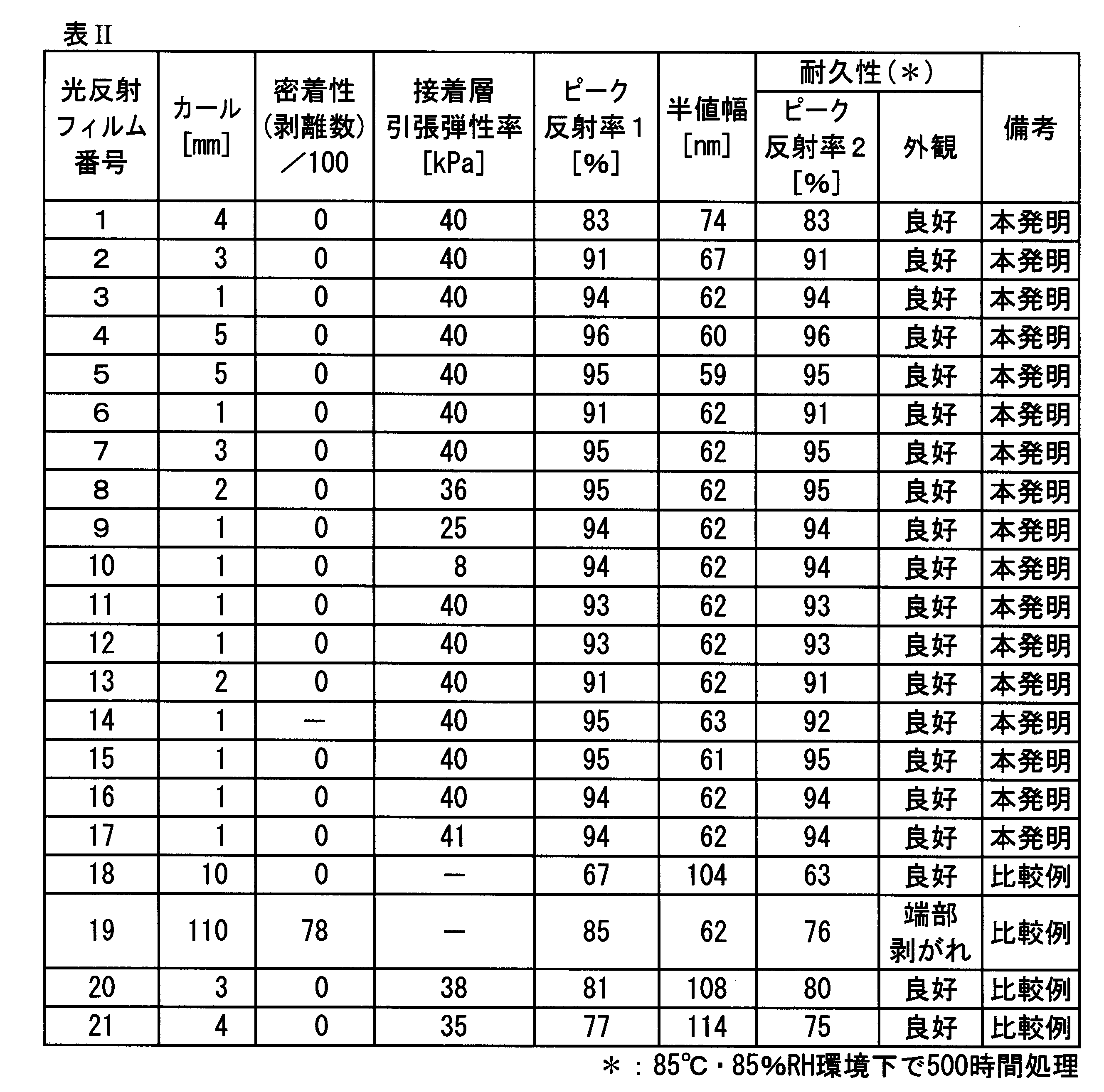
表IIに記載の結果より、本発明の光反射フィルムは、比較例に対し、カール、密着性、光学特性(ピーク反射率)及び耐久性に優れていることが分かる。
本発明の光反射フィルムは、カール、密着性、光学特性(ピーク反射率)及び耐久性に優れ、建物の屋外の窓や自動車窓等長期間太陽光に晒らされる設備(基体)に貼り合せ、熱線反射効果を付与する熱線反射フィルム等の窓貼用フィルム、農業用ビニールハウス用フィルム等に好適に利用できる。
1 光反射フィルム
1A 積層体
2A 基材フィルム1
2B 基材フィルム2
3A 第1反射層ユニット
3B 第2反射層ユニット
3C 第3反射層ユニット
5 転写フィルム
6 コーター
7 加圧ローラー
8 金属製加熱ローラー
9 紫外線照射光源
AL 接着層
AL1 接着層1
AL2 接着層2
F1 第1フィルムユニット
F2 第2フィルムユニット
P 会合点
1A 積層体
2A 基材フィルム1
2B 基材フィルム2
3A 第1反射層ユニット
3B 第2反射層ユニット
3C 第3反射層ユニット
5 転写フィルム
6 コーター
7 加圧ローラー
8 金属製加熱ローラー
9 紫外線照射光源
AL 接着層
AL1 接着層1
AL2 接着層2
F1 第1フィルムユニット
F2 第2フィルムユニット
P 会合点
Claims (6)
- 一対の基材フィルムと、屈折率の異なる層が2層以上積層されている反射層ユニットを二つ以上有する光反射フィルムであって、
前記二つ以上の反射層ユニット間に接着層を有し、当該接着層の層厚が0.1~1.0μmの範囲内であり、
かつ前記二つ以上の反射層ユニット及び接着層で構成される反射層ユニット群が、前記一対の基材フィルムで挟持されていることを特徴とする光反射フィルム。 - 前記二つ以上の反射層ユニットを有する構成において、接着層を挟んで対向する一方の反射層ユニットの層数をL1とし、他方の反射層ユニットの層数をL2としたとき、各反射層ユニットの層数の比の値L1/L2が0.5~1.5の範囲内であることを特徴とする請求項1に記載の光反射フィルム。
- 前記一対の基材フィルムの一方が、剥離可能な転写フィルムであることを特徴とする請求項1又は請求項2に記載の光反射フィルム。
- 前記接着層における無機微粒子の含有量が、接着層全体積に対し0~20体積%の範囲内であることを特徴とする請求項1から請求項3までのいずれか一項に記載の光反射フィルム。
- 請求項1から請求項4までのいずれか一項に記載の光反射フィルムを製造する光反射フィルムの製造方法であって、
基材フィルム上に反射層ユニットを有するフィルムユニットを二つ以上用い、二つの反射層ユニットを、接着層を介して貼合する工程を有することを特徴とする光反射フィルムの製造方法。 - 少なくとも二つの前記フィルムユニットを貼合するとき、一方のフィルムユニットが、基材フィルムとして剥離可能な転写フィルムを有し、前記転写フィルムを剥離した後、接着層を介して他方のフィルムユニットと貼合する工程を有することを特徴とする請求項5に記載の光反射フィルムの製造方法。
Applications Claiming Priority (2)
| Application Number | Priority Date | Filing Date | Title |
|---|---|---|---|
| JP2017093576A JP2020115157A (ja) | 2017-05-10 | 2017-05-10 | 光反射フィルム及び光反射フィルムの製造方法 |
| JP2017-093576 | 2017-05-10 |
Publications (1)
| Publication Number | Publication Date |
|---|---|
| WO2018207563A1 true WO2018207563A1 (ja) | 2018-11-15 |
Family
ID=64104458
Family Applications (1)
| Application Number | Title | Priority Date | Filing Date |
|---|---|---|---|
| PCT/JP2018/015888 Ceased WO2018207563A1 (ja) | 2017-05-10 | 2018-04-17 | 光反射フィルム及び光反射フィルムの製造方法 |
Country Status (2)
| Country | Link |
|---|---|
| JP (1) | JP2020115157A (ja) |
| WO (1) | WO2018207563A1 (ja) |
Cited By (6)
| Publication number | Priority date | Publication date | Assignee | Title |
|---|---|---|---|---|
| JP2020104513A (ja) * | 2018-11-22 | 2020-07-09 | 住友化学株式会社 | 積層フィルム巻回体、ハードコートフィルム付き積層体、及び偏光板 |
| TWI710458B (zh) * | 2019-07-26 | 2020-11-21 | 翔名科技股份有限公司 | 高反射鍍膜 |
| TWI738433B (zh) * | 2020-01-09 | 2021-09-01 | 致伸科技股份有限公司 | 光源模組以及具有光源模組的電子裝置 |
| CN114619739A (zh) * | 2022-03-11 | 2022-06-14 | 揭阳市千田塑胶有限公司 | 一种用于货车的防雨反光膜及其制备方法 |
| CN114762135A (zh) * | 2020-01-20 | 2022-07-15 | 冈本硝子株式会社 | 光阻墨水 |
| WO2022165886A1 (zh) * | 2021-02-04 | 2022-08-11 | 宁波瑞凌新能源科技有限公司 | 辐射制冷膜及其制品 |
Families Citing this family (2)
| Publication number | Priority date | Publication date | Assignee | Title |
|---|---|---|---|---|
| WO2022246173A1 (en) * | 2021-05-20 | 2022-11-24 | Sun Chemical Corporation | Oxygen barrier coating as a separation layer coating |
| JP7649398B1 (ja) | 2024-03-01 | 2025-03-19 | 日東電工株式会社 | 塗工装置、塗工方法、及び積層体の製造方法 |
Citations (2)
| Publication number | Priority date | Publication date | Assignee | Title |
|---|---|---|---|---|
| JP2009514037A (ja) * | 2005-10-31 | 2009-04-02 | スリーエム イノベイティブ プロパティズ カンパニー | 高コントラスト用途のための光学要素 |
| WO2016194875A1 (ja) * | 2015-06-01 | 2016-12-08 | コニカミノルタ株式会社 | 光学反射フィルム |
-
2017
- 2017-05-10 JP JP2017093576A patent/JP2020115157A/ja active Pending
-
2018
- 2018-04-17 WO PCT/JP2018/015888 patent/WO2018207563A1/ja not_active Ceased
Patent Citations (2)
| Publication number | Priority date | Publication date | Assignee | Title |
|---|---|---|---|---|
| JP2009514037A (ja) * | 2005-10-31 | 2009-04-02 | スリーエム イノベイティブ プロパティズ カンパニー | 高コントラスト用途のための光学要素 |
| WO2016194875A1 (ja) * | 2015-06-01 | 2016-12-08 | コニカミノルタ株式会社 | 光学反射フィルム |
Cited By (8)
| Publication number | Priority date | Publication date | Assignee | Title |
|---|---|---|---|---|
| JP2020104513A (ja) * | 2018-11-22 | 2020-07-09 | 住友化学株式会社 | 積層フィルム巻回体、ハードコートフィルム付き積層体、及び偏光板 |
| TWI710458B (zh) * | 2019-07-26 | 2020-11-21 | 翔名科技股份有限公司 | 高反射鍍膜 |
| TWI738433B (zh) * | 2020-01-09 | 2021-09-01 | 致伸科技股份有限公司 | 光源模組以及具有光源模組的電子裝置 |
| CN114762135A (zh) * | 2020-01-20 | 2022-07-15 | 冈本硝子株式会社 | 光阻墨水 |
| WO2022165886A1 (zh) * | 2021-02-04 | 2022-08-11 | 宁波瑞凌新能源科技有限公司 | 辐射制冷膜及其制品 |
| US11867434B1 (en) | 2021-02-04 | 2024-01-09 | Ningbo Radi-Cool Advanced Energy Technologies Co., Ltd. | Radiative cooling film and product thereof |
| CN114619739A (zh) * | 2022-03-11 | 2022-06-14 | 揭阳市千田塑胶有限公司 | 一种用于货车的防雨反光膜及其制备方法 |
| CN114619739B (zh) * | 2022-03-11 | 2023-12-19 | 揭阳市千田塑胶有限公司 | 一种用于货车的防雨反光膜及其制备方法 |
Also Published As
| Publication number | Publication date |
|---|---|
| JP2020115157A (ja) | 2020-07-30 |
Similar Documents
| Publication | Publication Date | Title |
|---|---|---|
| WO2018207563A1 (ja) | 光反射フィルム及び光反射フィルムの製造方法 | |
| JPWO2013111735A1 (ja) | 光学フィルム | |
| CN108369303B (zh) | 光学反射膜 | |
| US20170038508A1 (en) | Light reflective film roll and light reflective film roll package | |
| JP2018100987A (ja) | 遮熱フィルム用塗布液、遮熱フィルム用塗布液の製造方法及び赤外線遮蔽体 | |
| WO2017010280A1 (ja) | 熱線遮蔽フィルム | |
| JPWO2014188831A1 (ja) | 紫外線遮蔽フィルム | |
| JP6683249B2 (ja) | 光学反射フィルム | |
| JP6724912B2 (ja) | 光学反射フィルム | |
| JP2018116069A (ja) | 赤外遮蔽フィルム | |
| JP6176256B2 (ja) | 光学反射フィルムおよびそれを用いた光学反射体 | |
| JP6759697B2 (ja) | ロール状の光学反射フィルム | |
| JP6414081B2 (ja) | 光学反射フィルム | |
| CN116893455A (zh) | 光学层叠体、包括其的偏光板以及图像显示装置 | |
| JP2017219694A (ja) | 光学反射フィルム、光学反射フィルムの製造方法、及び、光学反射体 | |
| JP2018092039A (ja) | 光学反射フィルム | |
| WO2017077810A1 (ja) | 光反射フィルム | |
| JP6672984B2 (ja) | 光学反射フィルム、光学反射フィルムの製造方法、及び、光学反射体 | |
| WO2019240003A1 (ja) | 光学特性制御フィルム及びそれを用いた表示装置 | |
| JPWO2015037514A1 (ja) | 誘電体多層膜フィルムの製造方法 | |
| WO2019017221A1 (ja) | 光反射成型体 | |
| JP2016057537A (ja) | 光学反射フィルム、その製造方法およびそれを用いる光学反射体 | |
| WO2019193907A1 (ja) | 光学物品の製造方法及び光学物品 | |
| JP2016090878A (ja) | 光学反射フィルム |
Legal Events
| Date | Code | Title | Description |
|---|---|---|---|
| 121 | Ep: the epo has been informed by wipo that ep was designated in this application |
Ref document number: 18798397 Country of ref document: EP Kind code of ref document: A1 |
|
| NENP | Non-entry into the national phase |
Ref country code: DE |
|
| 122 | Ep: pct application non-entry in european phase |
Ref document number: 18798397 Country of ref document: EP Kind code of ref document: A1 |
|
| NENP | Non-entry into the national phase |
Ref country code: JP |