WO2018207289A1 - 医療機器 - Google Patents
医療機器 Download PDFInfo
- Publication number
- WO2018207289A1 WO2018207289A1 PCT/JP2017/017715 JP2017017715W WO2018207289A1 WO 2018207289 A1 WO2018207289 A1 WO 2018207289A1 JP 2017017715 W JP2017017715 W JP 2017017715W WO 2018207289 A1 WO2018207289 A1 WO 2018207289A1
- Authority
- WO
- WIPO (PCT)
- Prior art keywords
- end side
- distal end
- proximal end
- rod
- cylindrical portion
- Prior art date
- Legal status (The legal status is an assumption and is not a legal conclusion. Google has not performed a legal analysis and makes no representation as to the accuracy of the status listed.)
- Ceased
Links
Images











Classifications
-
- A—HUMAN NECESSITIES
- A61—MEDICAL OR VETERINARY SCIENCE; HYGIENE
- A61B—DIAGNOSIS; SURGERY; IDENTIFICATION
- A61B17/00—Surgical instruments, devices or methods
- A61B17/32—Surgical cutting instruments
Definitions
- This invention relates to a medical device.
- a medical device disclosed in US Pat. No. 6,068,647 has a distal end of a proximal end rod to which ultrasonic vibration from an ultrasonic transducer is transmitted from the proximal end toward the distal end, and a treatment portion at the distal end.
- the proximal end of the distal end side rod is screwed and used.
- a tool such as a torque wrench that connects the distal end of the proximal end side rod and the proximal end of the distal end side rod with an appropriate set torque is used.
- the medical device disclosed in US Pat. No. 6,068,647 is removed from the proximal end rod when the distal end rod itself is deteriorated or the distal end rod having a different-shaped treatment portion is to be used. And another front end side rod is connected with a base end side rod with a screw. At this time, since it is necessary to use a dedicated tool for connecting and releasing the distal end side rod with respect to the proximal end side rod, it is difficult to easily and appropriately replace it.
- An object of the present invention is to provide a medical device capable of easily and appropriately connecting and disconnecting the distal end side rod with respect to the proximal end side rod.
- a medical device includes an end effector, a first rod on a distal end side along a longitudinal axis, and a first tube portion in which the first rod is disposed inside,
- the second rod is disposed on the proximal end side of the first rod along the longitudinal axis, and transmits ultrasonic vibration to the end effector in a state of being disposed on the proximal end side of the first rod.
- a connector for restricting movement of the second cylindrical portion along the longitudinal axis of the first rod and the second rod, the outer peripheral surface of the first cylindrical portion, and the second cylinder Provided on at least one of the inner peripheral surfaces of the portion, and on the proximal side from the connector along the longitudinal axis, the outer peripheral surface of the first cylindrical portion and the inner peripheral surface of the second cylindrical portion And a support portion that regulates movement of the first tube portion in a direction intersecting the longitudinal axis with respect to the second tube portion in the connected state.
- the medical device which is attached to a distal end side assembly having a distal end side cylindrical portion and a distal end side rod supported inside the distal end side cylindrical portion from the proximal end side.
- the device is a base end side rod portion and a base end side rod that is supported on the inside of the base end side tube portion and has a tip that can come into contact with the base end of the tip end side rod.
- a proximal end rod whose proximal end is in contact with the distal end; and a proximal end tubular portion provided on the proximal end tubular portion; and the proximal end tubular portion is disposed outside the distal end side tubular portion; The proximal end and the distal end of the proximal rod are brought into contact with each other, and in the connected state, the distal end side cylindrical portion and the proximal end side cylindrical portion are connected to the distal end side rod and the proximal end side.
- a connector for restricting movement along the longitudinal axis of the rod and an inner peripheral surface of the base end side cylindrical portion Provided, supports an outer peripheral surface of the distal end side cylindrical portion on the proximal side along the longitudinal axis from the connector, and the distal end side tubular portion is longer than the proximal end side tubular portion in the connected state. And a support part that restricts movement in a direction intersecting the axis.
- the base end side assembly is attached from the front end side to a base end side assembly having a base end side cylindrical portion and a base end side rod supported inside the base end side cylindrical portion.
- the medical device used is a distal end side rod portion and a distal end side rod having a proximal end supported on the inner side of the distal end side barrel portion and capable of contacting the distal end of the proximal end side rod.
- a distal end side rod whose distal end is in contact with the proximal end; and provided on the distal end side cylindrical portion; and the proximal end side cylindrical portion is disposed outside the distal end side cylindrical portion; The proximal end and the distal end of the proximal end rod are brought into contact with each other, and in the connected state, the distal end side tubular portion and the proximal end side tubular portion are connected to the distal end side rod and the proximal end.
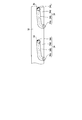
- FIG. 1A is a schematic cross-sectional view showing a state where a proximal end assembly and a distal end side assembly of the medical device according to the first embodiment are separated.
- FIG. 1B is a schematic view showing a cam ring having a cam groove as seen from the direction of arrow 1B in FIG. 1A.
- FIG. 1C is a schematic enlarged view of a portion indicated by reference numeral 1C in FIG. 1A.
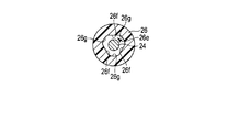
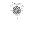
- FIG. 1D is a schematic cross-sectional view taken along line 1D-1D in FIG. 1A.
- FIG. 1E is a schematic cross-sectional view taken along line 1E-1E in FIG. 1A.
- FIG. 1F is a schematic cross-sectional view taken along line 1F-1F in FIG. 1A.
- FIG. 1A is a schematic cross-sectional view showing a state where a proximal end assembly and a distal end side assembly of the medical device according to the first embodiment are separated.
- FIG. 1B is
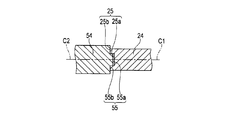
- FIG. 2A is a schematic diagram illustrating a state in which the distal end surface of the proximal end side vibration transmitting body of the proximal end side assembly of the medical device according to the first embodiment is in contact with the proximal end surface of the distal end side vibration transmitting body of the distal end side assembly.
- FIG. 2B is a schematic enlarged view of a portion indicated by reference numeral 2B in FIG. 2A.
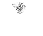
- 2C is a schematic cross-sectional view taken along line 2C-2C in FIG. 2A.
- FIG. 3A is a schematic cross-sectional view showing a state in which the proximal end assembly and the distal end side assembly of the medical device according to the first embodiment are connected.
- 3B is a development view showing a state in which the cam pins are arranged in the cam grooves.
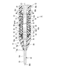
- 4A is a schematic partial cross-sectional view taken along line 4A-4A in FIG. 4B, showing a distal-end assembly of a medical device according to a modification of the first embodiment.
- 4B is a schematic partial cross-sectional view taken along line 4B-4B in FIG. 4A.
- 4C is a schematic cross-sectional view taken along line 4C-4C in FIG. 4A.
- 4D is a schematic cross-sectional view taken along line 4D-4D in FIG. 4A.
- 4E is a schematic cross-sectional view taken along line 4E-4E in FIG. 4A.
- FIG. 5A is a schematic view showing a proximal end assembly connectable to the distal end side assembly shown in FIG. 4A of a medical device according to a modification of the first embodiment.
- FIG. 5B is a schematic cross-sectional view taken along line 5B-5B in FIG. 5A.
- FIG. 6A is a schematic cross-sectional view showing a state where the proximal end assembly and the distal end side assembly of the medical device according to the second embodiment are separated.
- 6B is a schematic cross-sectional view taken along line 6B-6B in FIG. 6A.
- FIG. 7A is a schematic cross-sectional view illustrating a state in which a proximal end assembly and a distal end side assembly of a medical device according to a second embodiment are connected.
- FIG. 7B is a schematic cross-sectional view taken along line 7B-7B in FIG. 7A.
- a treatment instrument 10 as a medical device includes a proximal-end assembly (ultrasonic transducer unit) 12 and a distal-end assembly 14.
- the proximal end assembly (medical device) 12 and the distal end side assembly (medical device) 14 can be attached (connected) and removed (disconnected).
- the treatment instrument 10 is used for appropriate treatment of a living tissue in a state where the proximal end assembly 12 and the distal end assembly 14 are appropriately attached.
- the proximal end assembly 12 includes a first housing (base end side holding portion) 22 and a base end side rod (base end side vibration transmission body) 24.
- the first housing 22 includes an exterior case (second cylindrical portion) 26 and a first connector (base end side connector) 28.
- the proximal end side rod (second rod) 24 is formed of a metal material having good acoustic characteristics such as a titanium alloy material, a stainless alloy material, and an aluminum alloy material. For this reason, the proximal end side rod 24 is formed as a vibration transmitting body suitable for transmitting ultrasonic vibration from the proximal end side to the distal end side.
- the proximal end side rod 24 may be solid or hollow, that is, cylindrical.
- the proximal end side rod 24 defines a central axis (longitudinal axis) C1 by the proximal end portion and the distal end portion.
- the central axis C1 is preferably straight.
- the ultrasonic transducer unit 30 is arranged continuously to the proximal end of the proximal end side rod 24.
- the ultrasonic transducer unit 30 includes a flange portion (a transducer base) 30a supported in a state of being prevented from rotating by a holding portion 26b on an inner peripheral surface of an outer case 26 described later, and a proximal end side of the flange portion 30a. It has a fixed ultrasonic transducer 31 and a horn 30b that is integrally formed at the tip of the flange portion 30a and expands the ultrasonic vibration generated by the ultrasonic transducer 31.
- the proximal end rod 24 is integrally formed at the distal end of the horn 30b. However, the proximal end rod 24 may be screwed to the horn 30b.
- the proximal end side rod 24 on the distal end side of the horn 30b maintains a substantially constant outer diameter, but the outer diameter on the distal end side may be smaller than that on the proximal end side.
- the flange part (support part) 30a protrudes radially outward with respect to the central axis C1, and is formed in a shape other than a circle.
- a known BLT-type ultrasonic transducer 31 is disposed at the base end of the flange portion 30a.
- the ultrasonic transducer 31 is firmly fixed to the proximal end of the flange portion 30a.
- vibrator 31 will be ultrasonic-vibrated if an appropriate electric current is supplied to the ultrasonic transducer
- the child 31 vibrates.
- the proximal end rod 24 is directly abutted against the proximal end surface (proximal end abutting portion) 55 of a distal end side rod (first rod) 54 (to be described later) of the distal end side assembly 14 at the distal end thereof. (Tip side abutting portion) 25.
- the tip surface 25 has a surface orthogonal to the central axis C1.
- the proximal end side rod 24 is disposed inside the outer case 26.
- the outer case 26 is preferably formed of a plastic material having appropriate heat resistance and electrical insulation.
- the exterior case 26 has a main body (cylinder part) 26a formed in a cylindrical shape.
- the main body 26a is formed with a holding portion 26b that holds the flange portion 30a of the ultrasonic transducer unit 30 in a non-rotating state.
- the central axis C ⁇ b> 1 of the proximal end side rod 24 coincides with the central axis of the exterior case 26.
- the proximal end rod 24 of the proximal end assembly 12 can be disposed on the proximal end side of the distal end side rod 54 along the central axis (longitudinal axis) C1, and is disposed on the proximal end side of the distal end side rod 54.
- a treatment portion (end effector) 54d provided at the distal end portion of the distal end side rod 54.
- the outer case 26 of the base end side assembly 12 has an inner peripheral surface.
- the inner peripheral surface on the distal end side along the central axis C ⁇ b> 1 of the main body 26 a of the exterior case 26 is formed as a housing portion 26 c that receives a base 56 described later of the distal end side assembly 14.
- a housing portion (inner peripheral surface) 26 c of the outer case 26 faces an outer peripheral surface of a cylindrical portion 66 described later in a state where the proximal end rod 24 is disposed on the proximal end side of the distal end side rod 54.
- An annular recess 26d is formed on the inner peripheral surface of the distal end portion of the main body 26a of the outer case 26, that is, the inner peripheral surface of the distal end portion of the accommodating portion 26c.
- a first connector (base end side connector) 28 is fixed to the annular recess 26d. That is, the first connector 28 is provided on the inner peripheral surface of the outer case 26.
- the first connector 28 forms a connector (detachment mechanism) between the proximal end assembly 12 and the distal end assembly 14 in cooperation with a later-described second connector 60 of the distal end assembly 14.
- the connectors 28 and 60 are mutually rotated by rotating or rotating the first housing 22 and the second housing 52 around the first central axis C1 and the second central axis (longitudinal axis) C2. It can be connected to and can be disconnected.
- the first connector 28 has a cam ring 32 fixed to the annular recess 26d at the tip of the main body 26a of the outer case 26, and a cam groove 34 formed in the cam ring 32.
- the cam ring 32 is appropriately fixed to the distal end portion of the main body 26a of the outer case 26 by, for example, screwing or the like.
- the cam ring 32 has a distal end edge portion 32a and a proximal end proximal end portion 32b along the central axis C1.
- the base end edge portion 32b of the cam ring 32 is in contact with the annular recess 26d of the exterior case 26, and movement toward the base end side is regulated along the central axis C1.
- the cam groove 34 has an inlet (opening) 34 a at the tip edge portion 32 a of the cam ring 32.
- the inlet width of the inlet 34a along the circumferential direction of the cam ring 32 is formed to be slightly larger than the outer diameter of a cam pin 84 described later.
- Opposing cam surfaces (inclined surfaces) 34b are formed continuously at the inlet 34a.
- the width between the cam surfaces 34 b is formed to be slightly larger than the outer diameter of the cam pin 84.
- An engagement portion 34c that holds the cam pin 84 in an engaged state is formed continuously with the cam surface 34b at the distal end of the cam groove 34 with respect to the inlet 34a.
- a movement restricting portion 34d that restricts the cam pin 84 from moving from the engaging portion 34c to the cam surface 34b is formed.
- the number of cam grooves 34 may be one, but it is also preferable that there are a plurality of cam grooves 34, such as two or three (refer to modifications described later).
- a pair of cam grooves 34 oppose each other across the central axis C1. It is also preferable that the pair of cam grooves 34 is formed at an appropriate position such as a position 90 degrees away from each other around the central axis C1.
- the cam groove 34 is preferably formed as a concave groove that does not penetrate the cam ring 32 from the inlet 34a to the engaging portion 34c.
- the concave surface 35 formed by the cam groove 34 is located at a radius d1 from the central axis C1.
- a radius from the central axis C1 to the inner peripheral surface of the cam ring 32 is defined as d2 ( ⁇ d1).
- a portion of the cam pin 84 that is distal from the central axis C2 is located at an appropriate radius d3 (see FIG. 1A) from the central axis C2.
- the radius d3 is larger than the radius d2, and the radius d1 is larger than the radius d3.
- the distal end assembly 14 is disposed on the inner peripheral surface of the housing portion 26 c of the main body 26 a of the exterior case 26 along the central axis C ⁇ b> 1 and on the base end side of the annular recess 26 d.
- An inwardly projecting portion (supporting portion) 26e that can abut on an outer peripheral surface of an extending portion 66b of a cylindrical portion 66 described later is formed.
- an appropriate metal material can be used, and a plastic material, a rubber material, or the like can be appropriately used.
- the inward protruding portion 26e may be formed integrally with the main body 26a of the exterior case 26, or a separate body may be fixed.
- the inward protruding portion 26e is preferably formed in a substantially annular shape along the circumferential direction of the inner peripheral surface of the accommodating portion 26c.
- the inner peripheral surface of the inward protruding portion 26e can support the outer peripheral surface of the extending portion 66b at a plurality of positions.
- the inward protruding portion 26e has, on its inner peripheral surface, for example, three abutting portions 26f formed at positions separated by about 120 degrees around the central axis C1.
- the three contact portions 26f are formed, for example, as flat surfaces or curved surfaces, and support the outer peripheral surface of the extending portion 66b at approximately three points.
- the inward projecting portion 26e has an abutting portion 26f that supports the outer peripheral surface of the extending portion 66b at a position 120 degrees apart about the center axis C1, so that the distal end side assembly 14 with respect to the center axis C1.
- the center axis C2 of the cylindrical portion 66 can be made to coincide.
- a curved surface (separating portion) 26g in which a gap is formed between the inward protruding portion 26e and the extending portion 66b at a position away from the contact portion 26f that supports the outer peripheral surface of the extending portion 66b. Have For this reason, generation
- the inner peripheral surface of the distal end portion of the inward protruding portion 26e has an inclined surface 26h that is radially reduced in diameter with respect to the central axis C1 from the distal end side toward the proximal end side. For this reason, even if the central axis C2 of the extending portion 66b of the cylindrical portion 66 of the distal end side assembly 14 is deviated from the central axis C1 of the outer case 26 of the base end side assembly 12, the inward protrusion of the outer case 26 is achieved.
- the distal end side assembly When the proximal end of the extended portion 66b of the cylindrical portion 66 of the distal end side assembly 14 is brought into contact with the inclined surface 26h of the portion 26e, the distal end side assembly is made with respect to the central axis C1 of the exterior case 26 of the proximal end side assembly 12.
- the 14 cylindrical portions 66 are guided so that the central axes C2 of the extending portions 66b coincide with each other.
- the inward protruding portion 26e is in a state in which the distal end abutting portion (distal end surface) 25 of the proximal end side rod 24 and the proximal end surface 55 of the distal end side rod 54 are in contact with each other.
- the outer peripheral surface of the extending portion 66b of the cylindrical portion 66 faces or contacts the inner peripheral surface of the inward protruding portion 26e toward the central axes C1 and C2.
- the distance from the front end of the outer case 26 to the inclined surface 26h of the inward protruding portion 26e of the outer case 26 satisfies the following.
- the inclined surface 26h of the inward projecting portion 26e of the outer case 26 is formed on the distal end assembly 14. It can contact the base end of the cylindrical portion 66 (the base end of the extension portion 66b). At this time, the distal end surface 25 and the proximal end surface 55 are not in contact with each other.
- the distance from the front end of the exterior case 26 to the contact portion 26f of the inward protruding portion 26e of the exterior case 26 satisfies the following.
- the rotation center of the cam pin 84 of the distal end side assembly 14 is located on the proximal end side with respect to the inlet 34a of the cam groove 34 of the proximal end side assembly 12
- the contact portion 26f of the inward projecting portion 26e of the exterior case 26 is It can contact the outer peripheral surface of the extending portion 66b of the cylindrical portion 66 of the assembly 14.
- the distal end surface 25 and the proximal end surface 55 are in contact with each other.
- the front end side assembly 14 includes a second housing (front end side holding portion) 52 that can be attached to and detached from the first housing 22 and a front end side rod (front end side vibration transmitting body) 54.
- the second housing 52 includes a base body 56, a rotation knob (sheath) 58, and a second connector (tip-side connector) 60.
- a rotation knob 58 and a second connector 60 are disposed on the base 56.
- the distal end side rod 54 is formed of a metal material having good acoustic characteristics such as a titanium alloy material, a stainless alloy material, an aluminum alloy material, or the like. Therefore, the distal end side rod 54 is suitable for transmitting ultrasonic vibration transmitted from the proximal end side rod 24 from the proximal end side of the distal end side rod 54 to a treatment portion (end effector) 54d described later on the distal end side. It is formed as a vibration transmission body.
- the distal end side rod 54 may be solid or hollow, that is, cylindrical.
- the distal end side rod 54 defines a central axis C2 by a proximal end portion and a distal end portion.
- the central axis C2 is preferably straight.
- the distal end side rod 54 is formed with a flange portion 54a projecting radially outward from the central axis C2 between the proximal end portion and the distal end portion.
- the flange portion 54a is formed in a shape other than a circle.
- the distal end side rod 54 is formed with a first vibration transmitting portion 54b capable of transmitting vibration from the proximal end side toward the distal end side on the proximal end side of the flange portion 54a.
- the first vibration transmitting portion 54 b of the distal end side rod 54 has a proximal end surface 55 that directly abuts against the distal end surface 25 of the proximal end side assembly 12 at the proximal end.
- the proximal end surface 55 has a surface orthogonal to the central axis C2.
- the distal end surface 25 of the proximal end side rod 24 of the proximal end side assembly 12 is formed with a recess 25a and an annular surface (front end surface) 25b.
- the annular surface (tip surface) 25b is orthogonal to the central axis C1.
- a convex portion 55a and an annular surface (base end surface) 55b are formed on the proximal end surface 55 of the distal end side rod 54 of the distal end side assembly 14.
- the annular surface (tip surface) 55b is orthogonal to the central axis C2.
- the recessed part 25a and the convex part 55a can be fitted in the state in which the annular surfaces 25b and 55b were abutted.
- the vibration generated in the ultrasonic transducer 31 is transmitted from the proximal end side of the proximal end rod 24 to the distal end side of the distal end rod 54 through the annular surfaces 25b and 55b. It can be transmitted to the treatment section 54d.
- a gap is formed between the concave portion 25a and the convex portion 55a. In this case, the frequency of the ultrasonic vibration transmitted from the proximal end side rod 24 to the distal end side rod 54 is adjusted by adjusting the amount of the gap.
- the outer diameter of the proximal end surface 55 of the distal end side rod 54 is preferably the same as or slightly larger than the outer diameter of the distal end surface 25 of the proximal end side rod 24.
- the outer diameter of the proximal end surface 55 of the distal end side rod 54 may be formed slightly smaller than the outer diameter of the distal end surface 25 of the proximal end side rod 24.
- the distal end side rod 54 includes a second vibration transmitting portion 54c capable of transmitting vibration from the proximal end side toward the distal end side, and a second vibration transmitting portion 54c on the distal end side of the flange portion 54a. It has a treatment part (end effector) 54d formed at the tip and treating living tissue.
- the treatment portion 54d can select, for example, a blade shape, a hook shape, a spatula shape, or the like according to the treatment target.
- the treatment portion 54d may be appropriately bent at the tip of the second vibration transmission portion 54c.
- Each of the first vibration transmitting portion 54b and the second vibration transmitting portion 54c may hold a substantially constant outer diameter from the base end portion to the tip end portion, and as shown in FIG. The outer diameter may be reduced from the end side toward the tip side.
- the base body 56 is formed in a cylindrical shape through which the distal end side rod 54 is inserted.
- the substrate 56 is preferably formed of a plastic material having appropriate heat resistance and electrical insulation.
- the base 56 includes a base portion 62 formed in a cylindrical block shape, a knob connecting portion 64 formed on the distal end side of the base portion 62, and a tubular portion (first tubular portion) formed on the proximal end side of the base portion 62. 66. In this embodiment, the description will be made assuming that the base 62, the knob connecting portion 64, and the cylindrical portion 66 are integrated.
- the first vibration transmitting portion 54 b of the distal end side rod 54 is disposed inside the base body 56.
- the base end side rod of the base end side assembly 12 is placed inside the cylindrical portion 66 of the base body 56. 24 is arranged.
- the inner diameter of the base body 56 (the inner diameter of the cylindrical portion 66) is slightly smaller than the outer diameter of the first vibration transmitting portion 54b of the distal end side rod 54 of the distal end side assembly 14 and the proximal end side rod 24 of the proximal end side assembly 12. Largely formed.
- a gap is formed between the inner peripheral surface of the base 56 and the outer peripheral surface of the first vibration transmitting portion 54b, and the first vibration transmitting portion 54b is connected to the inner peripheral surface of the cylindrical portion 66 of the base 56. It can rotate around the central axis C2.
- Rotating knob 58 formed in a cylindrical shape is connected to knob connecting portion 64 so as to be rotatable around a central axis C2.
- the rotary knob 58 preferably serves as a sheath that covers the outer periphery of the second vibration transmitting portion 54c of the distal end side rod 54 with the treatment portion 54d at the distal end of the distal end side rod 54 protruding from the distal end. .
- the rotary knob 58 includes a knob main body 72, a base connecting portion 74 connected to a knob connecting portion 64 formed on the distal end side of the base portion 62, and a holding portion 76 that holds the distal end side rod 54 in a state where it is prevented from rotating.
- a knob main body 72 In the knob main body 72, the distal end side rod 54 is inserted, and the treatment portion 54d projects from the distal end of the rotary knob 58 toward the distal end side along the central axis C2.
- the outer peripheral surface of the knob main body 72 is formed as an operation unit (rotation operation unit) 72a that allows the user to rotate the knob 58 about the central axis C2.
- the inner peripheral surface of the tip end of the knob body 72 is formed as a holding portion 72 b that holds the outer periphery of the second vibration transmitting portion 54 c of the tip end side rod 54.
- the holding portion 72b is at a position corresponding to the node position of vibration when ultrasonic vibration is transmitted.
- a holding portion 76 is formed on the inner peripheral surface of the knob body 72 of the rotary knob 58.
- the holding portion 76 holds the flange portion 54a of the distal end side rod 54 in a state in which the rotation is prevented.
- This holding position is such that the proximal end surface 55 of the distal end side rod 54 abuts on the distal end surface 25 of the proximal end side rod 24 of the proximal end side assembly 12, and the proximal end of the proximal end side rod 24 extends to the distal end of the distal end side rod 54. It is a position that becomes a node position of vibration in a state where vibration is transmitted.
- the operation portion (rotation operation portion) on the outer peripheral surface of the knob body 72 of the rotary knob 58 is rotated or rotated around the central axis C2.
- the distal end side rod 54 rotates or rotates around the axis of the central axis C2 as the knob main body 72 of the rotating knob 58 rotates or rotates. That is, the distal end side rod 54 can freely rotate or rotate with respect to the base portion 62 and the cylindrical portion 66 of the base body 56.
- a plurality of balls 78 are supported on the base connecting portion 74 at appropriate intervals around the central axis C2. And the friction between the knob connection part 64 and the base
- the ball 78 is described as being supported by the base connecting portion 74 in this embodiment, it is needless to say that the ball 78 may be supported by the knob connecting portion 64. That is, a plurality of balls 78 are supported between the knob connecting portion 64 and the rotary knob 58, and in particular, a plurality of balls 78 are preferably supported on one of the knob connecting portion 64 and the rotary knob 58. . For this reason, the frictional force of rotation between the knob coupling part 64 and the rotary knob 58 is reduced.
- a bearing that allows rotation or rotation around the central axis C2 such as a thrust ball bearing is provided between the knob connecting portion 64 and the rotary knob 58. It is also suitable that they are arranged in between.
- a lubricating sheet member, an oil-free bush, or the like is preferably disposed between the knob connecting portion 64 and the rotary knob 58.
- a pressing force is generated between the knob connecting portion 64 of the base 56 and the base connecting portion 74 of the rotary knob 58 in a state where the connection between the proximal end assembly 12 and the distal end assembly 14 is released. Preferably not. At this time, an appropriate backlash may occur between the knob connecting portion 64 of the base 56 and the base connecting portion 74 of the rotary knob 58.
- the tip assembly 14 is a single body, no large pressing force is generated between the knob connecting portion 64 of the base 56 and the base connecting portion 74 of the rotary knob 58, and the rotary knob 58 is moved against the base 56. When rotating or rotating around the central axis C2, it can be easily operated.
- a pressing force of, for example, about 0 to 500 N is applied between the knob connecting portion 64 of the base 56 and the base connecting portion 74 of the rotary knob 58 in a state where the base end side assembly 12 and the distal end side assembly 14 are connected. Occurs.
- a second connector 60 is formed between the base end of the base portion 62 of the base body 56 and the base end of the cylindrical portion 66. That is, the second connector 60 is provided on the outer peripheral surface of the cylindrical portion 66.
- the second connector 60 includes a slider 82, a cam pin 84, and an urging body 86.
- annular contact portion (slider proximity portion) 62a with which the slider 82 is urged and contacted by the urging body 86 is formed.
- the contact portion 62a is formed at the tip of the cylindrical portion 66 of the base body 56, and is formed as an outer flange that protrudes radially outward with respect to the central axis C2.
- an outer flange 66a that protrudes radially outward with respect to the central axis C2 is formed.
- the cylindrical portion 66 has an extending portion 66b that extends to a position closer to the base end side than the position where the outer flange 66a is formed.
- the outer flange 66a may be formed integrally with the cylindrical portion 66, or may be attached from the outside.
- a ring-shaped slider 82 is disposed outside the cylindrical portion 66 of the base 56.
- the slider 82 can move between the contact portion 62a and the outer flange 66a along the central axis C2 in cooperation with the outer peripheral surface of the cylindrical portion 66 of the base 56.
- the slider 82 is prevented from rotating with respect to the outer periphery of the cylindrical portion 66, and is prevented from rotating or rotating about the central axis C2.
- the cam pin 84 includes a holding portion 84a that is held in a state where it is prevented from being detached from the slider 82, and a rotating body 84b that is rotatable with respect to the holding portion 84a.
- the cam pin 84 does not move in the circumferential direction with respect to the slider 82, and can rotate or rotate about an axis orthogonal to the central axis C2.
- the rotating body 84b is at a position distal to the central axis C2 in the radial direction in the cam pin 84.
- the rotating body 84b protrudes outward in the radial direction of the central axis C2 from the ring-shaped slider 82 and the outer flange 66a at the proximal end of the cylindrical portion 66.
- cam pin 84 Only one cam pin 84 may be disposed on the slider 82, but a plurality of cam pins 84 such as two as shown in FIG. 1F are preferable.
- two (a pair) of cam pins 84 are engageable with a pair of cam grooves 34 and are about each other about the center axis C2. It is disposed at a position 180 degrees apart. It is also preferable that the cam pins 84 are disposed at appropriate positions such as a position 90 degrees apart or a position 120 degrees away from each other around the central axis C2.
- the biasing body 86 is a compression coil spring in this embodiment.
- the urging body 86 is supported on the outer side of the cylindrical portion 66 between the outer flange 66 a at the proximal end of the cylindrical portion 66 and the slider 82. Since the biasing body 86 resists the force to be compressed, the slider 82 is biased against the outer flange 66a along the central axes C1 and C2 to the contact portion 62a of the base portion 62 on the distal end side. .
- a disc spring, a multiple disc spring, or the like can be used as appropriate in addition to the compression coil spring.
- the proximal end assembly 12 When the proximal end assembly 12 is connected to the distal end side assembly 14 at the proximal end of the base portion 62 of the base body 56, the distal end of the main body 26a of the outer case 26 is brought into contact with or close to the annular end.
- a facing surface 62b is formed. The facing surface 62b is formed outside the contact portion 62a.
- the boundary (contact portion) between the distal end surface 25 of the proximal end side rod 24 and the proximal end surface 55 of the distal end side rod 54 is based on the characteristics of the ultrasonic transducer 31 so as to be the antinode position of vibration.
- the length of the end side rod 24 is adjusted.
- the drive frequency at which the ultrasonic transducer 31 used in a treatment instrument for treating living tissue is driven is, for example, about 10 kHz to 100 kHz.
- the proximal end rod 24 but also the distal end rod 54 changes in length along the central axis C2.
- a foot switch (not shown) that switches ON / OFF of energy supply to the ultrasonic transducer 31 is connected to a power source to which the treatment instrument 10 is connected. While the foot switch pedal is being pressed, energy is continuously supplied to the ultrasonic transducer 31 and the ultrasonic transducer 31 continues to generate ultrasonic vibrations. When the pedal is released and switched to the OFF state, the output of energy to the ultrasonic transducer 31 is stopped, and the generation of ultrasonic vibration in the ultrasonic transducer 31 is stopped.
- the switch may be a hand switch as shown in FIGS. 4A and 4B of a modified example described later.
- a case will be described in which the first connector 28 of the proximal end assembly 12 and the second connector 60 of the distal end assembly 14 are connected to attach the proximal end assembly 12 to the distal end assembly 14.
- the user holds the base body 56 of the distal end side assembly 14 with the left hand and the outer case 26 of the proximal end side assembly 12 with the right hand.
- the distal end of the outer case 26 of the proximal end assembly 12 and the proximal end of the cylindrical portion 66 of the distal end assembly 14 are opposed to each other.
- the central axis C2 of the distal end side assembly 14 is made to coincide with the central axis C1 of the proximal end side assembly 12.
- the distal end assembly 14 is moved toward the proximal end relative to the proximal end assembly 12 along the central axes C ⁇ b> 1 and C ⁇ b> 2, and the cylindrical portion 66 of the distal end assembly 14 is moved to the exterior case of the proximal end assembly 12. It accommodates in 26 accommodating parts 26c. For this reason, the 1st connector 28 and the 2nd connector 60 are made to adjoin.
- proximal end side rod 24 and the outer case 26 do not move in the proximal end side assembly 12. That is, it is assumed that the proximal end rod 24 and the central axis C1 of the outer case 26 are kept in agreement.
- the front end assembly 14 may have a backlash between the base body 56 and the rotary knob 58 that supports the front end side rod 54.
- the central axis of the base body 56 and the central axis C2 of the distal end side rod 54 may be misaligned.
- the central axis C2 of the extending portion 66b of the cylindrical portion 66 of the distal end side assembly 14 may be displaced from the central axis C1 of the exterior case 26 of the proximal end side assembly 12.
- the base end of the extended portion 66b of the cylindrical portion 66 of the distal end side assembly 14 abuts on the inclined surface 26h of the inward protruding portion 26e of the exterior case 26.
- the distal end surface 25 of the proximal end side rod 24 and the proximal end surface 55 of the distal end side rod 54 are not in contact with each other.
- the inclined surface 26h is radially reduced in diameter with respect to the central axis C1 from the distal end side toward the proximal end side.
- the proximal end of the extending portion 66b of the cylindrical portion 66 of the distal end side assembly 14 is guided so that the central axis C2 coincides with the central axis C1 of the exterior case 26 of the proximal end assembly 12.
- the outer peripheral surface of the extending portion 66b of the cylindrical portion 66 of the distal end side assembly 14 is supported by the contact portion 26f of the inward protruding portion 26e of the exterior case 26 of the proximal end side assembly 12. That is, the outer peripheral surface of the extending portion 66b of the cylindrical portion 66 is supported at, for example, three points by the contact portion 26f of the inwardly protruding portion 26e of the outer case 26.
- the central axis C2 of the cylindrical portion 66 of the distal end side assembly 14 coincides with the central axis C1 of the exterior case 26 of the proximal end side assembly 12.
- the distal end surface 25 of the proximal end side rod 24 of the proximal end side assembly 12 and the proximal end surface 55 of the distal end side rod 54 of the distal end side assembly 14 abut.
- the inward protruding portion 26e is closer to the base end side along the central axes C1 and C2 than the outer flange 66a.
- FIG. 2A shows a state in which the distal end surface 25 of the proximal end side rod 24 of the proximal end side assembly 12 and the proximal end surface 55 of the distal end side rod 54 of the distal end side assembly 14 are in contact with each other.
- An annular surface (front end surface) 25b orthogonal to the central axis C1 of the distal end surface 25 of the proximal end side rod 24, and an annular surface (base end surface) 55b orthogonal to the central axis C2 of the proximal end surface 55 of the distal end side rod 54 Are in contact. For this reason, the central axis C1 of the proximal end side rod 24 and the central axis C2 of the distal end side rod 54 coincide.
- the central axes C ⁇ b> 1 and C ⁇ b> 2 of the proximal end rod 24 and the distal end side rod 54 coincide with each other due to contact between the distal end surface 25 and the proximal end surface 55.
- the adhesion force due to the urging force of the urging body 86 is not applied between the distal end surface 25 and the base end surface 55.
- the inner projecting portion 26e of the outer case 26 supports the outer peripheral surface of the cylindrical portion 66, whereby the central axis C2 of the distal end side rod 54 of the distal end side assembly 14 and the cylindrical portion 66 of the base body 56 is changed to the proximal end side rod. 24 and the center axis C1 of the outer case 26.
- the cam pin 84 of the second connector 60 of the assembly 14 is located at the inlet 34 a of the cam groove 34 of the first connector 28 of the proximal end assembly 12. At this time, the cam pin 84 is closer to the proximal end along the central axes C1 and C2 than the distal end edge portion 32a of the cam ring 32.
- the inner projecting portion 26e of the outer case 26 and the cylindrical portion 66 are extended from the connectors 28 and 60 in a state where the distal end surface 25 of the proximal end side rod 24 and the proximal end surface 55 of the distal end side rod 54 are in contact with each other.
- the distance to the outer peripheral surface of the portion 66b is a direction in which the cylindrical portion 66 intersects the exterior case 26 immediately before the connection state, such as a direction orthogonal to the axial directions of the central axes C1 and C2 by the inward protruding portion 26e. It is configured to regulate movement to.
- the first connector 28 and the second connector 60 are in a connectable state.
- the distal end surface 25 of the proximal end side rod 24 and the proximal end surface 55 of the distal end side rod 54 are brought into contact with each other, and the distal end side rod 54 of the distal end side assembly 14 and the central axis C2 of the cylindrical portion 66 of the base body 56 are connected to the proximal end side rod.
- 24 and the outer case 26 are rotated about the central axis C1 with respect to the central axis C2 of the base body 56 in a state of being aligned with the central axis C1 of the outer case 26.
- the first connector 28 moves from the inlet 34a of the cam groove 34 of the cam ring 32 toward the engaging portion 34c through the cam surface 34b.
- the slider 82 is movable along the central axis C2 with respect to the cylindrical portion 66, but rotation around the central axis C2 is prevented.
- the cam pin 84 of the second connector 60 disposed on the slider 82 only moves to the proximal end side along the central axis C2.
- the slider 82 resists the urging force of the urging body 86 toward the outer flange 66a of the cylindrical portion 66.
- the rotating body 84b of the cam pin 84 rotates around an axis orthogonal to the central axis C2. For this reason, the cam pin 84 moves from the inlet 34a toward the engaging portion 34c along the cam surface 34b of the cam groove 34 while the rotating body 84b rotates.
- the rotating body 84b of the cam pin 84 rotates, the friction between the cam pin 84 and the cam surface 34b of the cam groove 34 is reduced as compared with the case where the cam pin 84 is fixed to the slider 82.
- the cam pin 84 moves from the inlet 34a toward the engaging portion 34c with a relatively light force. Therefore, the cam pin 84 moves along the inlet 34a and the cam surface 34b of the cam groove 34 and is engaged with the engaging portion 34c in a state where the friction with respect to the cam surface 34b is reduced.
- the position of the slider 82 is closer to the proximal side along the central axes C1 and C2 than the position shown in FIG. 2A, as shown in FIG. 3A. It is in.
- the movement of the proximal end side rod 24 of the proximal end side assembly 12 along the central axis C ⁇ b> 1 with respect to the exterior case 26 is restricted.
- the distal end side rod 54 of the distal end side assembly 14 is restricted from moving along the central axis C ⁇ b> 2 with respect to the knob body 72.
- the first connector 28 of the proximal end assembly 12 and the second connector 60 of the distal end assembly 14 are moved outwardly of the cylindrical portion 66.
- the flange 66a is urged toward the base end side along the central axes C1 and C2 by the urging body 86.
- the outer flange 66a of the cylindrical portion 66 is pressed toward the proximal end along the central axes C1 and C2 by the biasing force of the biasing body 86. Therefore, the base portion 62 of the base body 56 of the distal end side assembly 14 in which the cylindrical portion 66 is integrated is pulled toward the proximal end side of the proximal end side assembly 12 by the proximal end side assembly 12.
- the rotary knob 58 is connected to the distal end side of the base 62 by the knob connecting portion 64 and the base connecting portion 74 in a state where movement in the direction along the central axis C2 is restricted.
- the rotary knob 58 supports the flange portion 54a of the distal end side rod 54 in a state where movement in the direction along the central axis C2 is restricted. Further, the movement of the proximal end side rod 24 of the proximal end side assembly 12 along the central axis C ⁇ b> 1 with respect to the exterior case 26 is restricted.
- the urging force by the urging body 86 is applied as a force that presses the distal end surface 25 of the proximal end side rod 24 of the proximal end side assembly 12 against the proximal end surface 55 of the distal end side rod 54 of the distal end side assembly 14. Is done. Accordingly, an abutting force is applied between the distal end surface 25 of the proximal end side rod 24 of the proximal end side assembly 12 and the proximal end surface 55 of the distal end side rod 54 of the distal end side assembly 14.
- the abutting force between the distal end surface 25 of the proximal end side rod 24 and the proximal end surface 55 of the distal end side rod 54 is the proximal end side. It acts as a reaction force loaded from the front end surface 25 of the rod 24 to the front end side along the central axis C2. Then, the reaction force is transmitted to the rotary knob 58 by the flange portion 54 a of the distal end side rod 54. Therefore, the rotary knob 58 is pressed together with the distal end side rod 54 toward the distal end side along the central axis C2. For this reason, the backlash between the rotary knob 58 and the base 62, that is, the axial displacement with respect to the central axis C2 is eliminated.
- the abutting force between the distal end surface 25 of the proximal end side rod 24 of the proximal end side assembly 12 and the proximal end surface 55 of the distal end side rod 54 of the distal end side assembly 14 is adjusted by a biasing body 86.
- the urging force of the urging body 86 can be set as appropriate, the base 56 is appropriately rotated with respect to the central axes C1 and C2 with the same hand while holding the outer case 26 with one hand when the treatment instrument 10 is used. Even if it tries to make it, the grade which maintains the fitting (state in which the cam pin 84 is arrange
- the urging force of the urging body 86 (the abutting force between the distal end surface 25 of the proximal end side rod 24 and the proximal end surface 55 of the distal end side rod 54) is an ultrasonic vibration generated by the ultrasonic transducer 31. It is necessary that the base end side rod 24 can be satisfactorily transmitted from the base end side rod 24 to the front end side rod 54.
- the biasing body 86 has an unreasonable force greater than a predetermined force between the distal end surface 25 of the proximal end side rod 24 of the proximal end side assembly 12 and the proximal end surface 55 of the distal end side rod 54 of the distal end side assembly 14. Is prevented from being added.
- first connector 28 of the proximal end assembly 12 and the second connector 60 of the distal end assembly 14 are connected. That is, the first connector 28 and the second connector 60 are in a connected state.
- the treatment instrument 10 has the exterior case 26 disposed outside the cylindrical portion 66, and the connectors 28 and 60 are used to connect the proximal end surface (base end) 55 of the distal end side rod 54 and the distal end surface of the proximal end side rod 24 ( It is in a connected state in a state where it is in contact with the tip 25.
- the cylindrical portion 66 and the outer case 26 are restricted from moving along the axial directions of the central axes C ⁇ b> 1 and C ⁇ b> 2 of the distal end side rod 54 and the proximal end side rod 24.
- the inward protruding portion 26e of the outer case 26 has an outer peripheral surface of the cylindrical portion 66 and an inner peripheral surface (accommodation of the outer case 26) on the base end side along the axial directions of the central axes C1 and C2 with respect to the connectors 28 and 60. And the portion 26c).
- the inward protruding portion 26e of the outer case 26 restricts the cylindrical portion 66 from moving in an intersecting direction, such as a direction orthogonal to the axial directions of the central axes C1 and C2, with respect to the outer case 26 in a connected state. ing.
- the proximal end assembly (medical device) 12 is attached from the proximal end side to the distal end assembly 14 having the distal end side cylindrical portion 66 and the distal end side rod 54 supported on the inner side of the distal end side cylindrical portion 66. And used as the treatment instrument 10.
- the proximal end assembly 12 is supported on the inner side of the exterior case (base end side cylindrical portion) 26 and the exterior case 26, and can be brought into contact with the proximal end (base end surface 55) of the distal end side rod 54 (distal end surface 25.
- a connector 28 that restricts movement of the cylindrical portion 66 and the exterior case 26 along the axial direction of the distal end side rod 54 and the proximal end side rod 24 in the connected state; It is provided on the peripheral surface (accommodating portion 26c), supports the outer peripheral surface of the cylindrical portion 66 on the proximal side along the axial direction from the connector 28, and the cylindrical portion 66 is axially connected to the exterior case 26 in a connected state. Move in intersecting directions, such as orthogonal directions Inwardly projecting portion for restricting the Rukoto and a (supporting portion) 26e.
- the user appropriately holds the treatment instrument 10 in this state, generates ultrasonic vibration with the ultrasonic vibrator 31 by supplying power from the power supply, and appropriately treats the treatment target with the treatment unit 54d.
- the rotation knob 58 of the distal end assembly 14 When changing the orientation of the treatment portion 54d, for example, while holding the outer case 26 of the proximal end assembly 12 and the base portion 62 of the distal end assembly 14 with the right hand, the rotation knob 58 of the distal end assembly 14 is gripped and the central axis C1, Rotate around the C2 axis.
- the rotation knob 58 can be rotated around the axis of the central axis C2 with respect to the proximal end assembly 12 and the base body 56, but they can be rotated in either direction.
- the distal end side rod 54 that is prevented from rotating around the rotary knob 58 rotates around the second central axis C2 together with the rotary knob 58.
- the substrate 56 does not rotate with the rotary knob 58.
- the proximal end rod 24 that is prevented from rotating around the outer case 26 maintains the state as it is together with the ultrasonic transducer unit 30.
- the distal end surface 25 of the proximal end side rod 24 of the proximal end side assembly 12 and the proximal end surface 55 of the distal end side rod 54 of the distal end side assembly 14 slide with respect to each other about the axes of the central axes C1 and C2. Rotate.
- the treatment tool 10 can adjust the orientation of the treatment portion 54d without moving the proximal end side rod 24, the exterior case 26, and the ultrasonic transducer unit 30.
- the inner projecting portion 26e of the outer case 26 of the proximal end assembly 12 is in contact with the outer peripheral surface of the cylindrical portion 66 of the distal end side assembly 14, and the state where the central axes C1 and C2 are made to coincide is maintained. To do.
- the operation for changing the orientation of the treatment section 54d may be performed with one hand or both hands.
- the left hand grasps the rotation knob 58 of the distal end assembly 14
- the right hand grasps the exterior case 26 of the proximal end assembly 12 and the base portion 62 of the distal end side assembly 14, moves the left hand, and rotates with respect to the exterior case 26.
- the knob 58 may be rotated relative to the central axes C1 and C2.
- the base 56 of the distal end side assembly 14 of the left hand and the exterior case 26 of the proximal end assembly 12 of the right hand are subjected to such a force that they cannot be moved by one hand in the opposite directions around the central axes C1 and C2.
- the cam pin 84 of the second connector 60 gets over the movement restricting portion 34d from the engaging portion 34c of the cam groove 34 of the first connector 28 and is disposed on the cam surface 34b and removed.
- the rotating surface 84b of the cam pin 84 rotates around the axis thereof, and the cam surface 34b of the cam groove 34 enters the entrance. Slip toward 34a. For this reason, the abutment between the distal end surface 25 of the proximal end side rod 24 of the proximal end side assembly 12 and the proximal end surface 55 of the distal end side rod 54 of the distal end side assembly 14 is released.
- the cam pin 84 is taken out from the inlet 34a of the cam groove 34.
- the connection between the first connector 28 of the proximal end assembly 12 and the second connector 60 of the distal end assembly 14 is released.
- the base end side assembly 12 is moved to the base end side along the central axis C1
- the tip end side assembly 14 is moved to the front end side along the central axis C2 to separate them.
- the cylindrical portion 66 of the base body 56 of the distal end side assembly 14 is taken out from the accommodating portion 26 c of the proximal end side assembly 12.
- the distal end side assembly 14 having the treatment portion 54d of another shape when using the distal end side assembly 14 having the treatment portion 54d of another shape, it is used by being connected to the proximal end side assembly 12 as described above.
- the proximal end assembly 12 is preferably reused after being cleaned, disinfected and sterilized.
- the front end assembly 14 is preferably discarded as it is.
- the distal end assembly 14 may be reused after being cleaned, disinfected and sterilized.
- a rotation knob 58 is appropriately disposed with respect to the base portion 62 of the base body 56 of the distal end side assembly 14, and the distal end side rod 54 and the rotation are rotated. It is possible that the center axis of the knob 58 and the center axis of the base 62 are misaligned.
- the first connector 28 of the proximal end assembly 12 and the second connector 60 of the distal end assembly 14 are connected to attach the proximal end assembly 12 to the distal end assembly 14, the proximal end rod 24 of the proximal end assembly 12.
- the distal end side rod 54 of the distal end side assembly 14 and the central axis C2 of the cylindrical portion 66 are used by the inwardly projecting portion 26e and the connectors 28, 60 provided on the exterior case 26.
- the frictional force between one cam pin 84 and one cam groove 34 (one coupling structure) and the frictional force between the other cam pin 84 and the other cam groove 34 (the other coupling structure) can be made as uniform as possible. That is, the operational feeling at the time of connection in a plurality of connection structures can be made uniform.
- a medical device capable of reliably transmitting ultrasonic vibration from the proximal end of the proximal end side rod 24 toward the distal end of the distal end side rod 54 is provided. can do.
- the distal end side rod 54 on the treatment portion 54d side is easily and appropriately connected to the proximal end side rod 24 on the ultrasonic transducer 31 side. Can do. Further, the distal end side rod 54 on the treatment portion 54d side can be easily and appropriately disconnected from the proximal end side rod 24 on the ultrasonic transducer 31 side.
- the central axis C1 of the proximal end side rod 24 and the central axis C2 of the distal end side rod 54 are connected to the distal end surface 25 and the base surface 25c. Even if the surfaces are in contact with each other by the contact between the end surfaces 55, the center axis C1 of the outer case 26 and the center axis C2 of the cylindrical portion 66 may be inclined and tilted.
- the frictional force between one cam pin 84 and one cam groove 34 causes the other cam pin 84 and the other cam groove 34 to move. Compared with the frictional force between 34, it can be very large.
- the treatment instrument 10 can input high-frequency energy to the proximal-side assembly 12 together with the ultrasonic vibration or instead of the ultrasonic vibration by a known mechanism.
- the treatment tool 10 which treats a biological tissue using ultrasonic vibration
- high-frequency energy when performing a treatment using high-frequency energy, a counter electrode attached to a patient is required.
- treatment can be performed by transferring heat to the treatment portion (end effector) 54d using a heater. Such energy switching is performed by, for example, a hand switch or a foot switch.
- a living tissue can be treated by a known mechanism by transferring heat to the treatment portion 54d using a heater together with ultrasonic vibration and / or high frequency energy.
- the base body 56 of the distal end side assembly 14 is formed of two bodies 56a and 56b.
- the first body 56a and the second body 56b are integrated by fitting the boss 57b into the boss hole 57a.
- a plurality of boss holes 57a are formed in the first body 56a
- a plurality of bosses 57b that can be fitted into the boss holes 57a of the first body 56a are formed in the second body 56b.
- the first body 56a and the second body 56b are fitted at a plurality of locations.
- a switch assembly 90 is disposed on the distal end side assembly 14.
- the switch assembly 90 is electrically connected to a power source (not shown) when the proximal end assembly 12 is attached to the distal end side assembly 14 although it is well known and will not be described.
- a power source not shown
- appropriate buttons 91a, 91b, 91c of the switch assembly 90 are selectively pressed, appropriate energy is output from the power source, and ultrasonic vibration or high-frequency current is output from the treatment unit 54d based on the pressed buttons. Etc. are output.
- the outer flange 66a is not integrated with the outer peripheral surface of the cylindrical portion 66 shown in FIG. 4A.
- an annular body (washer) 66c is disposed on the outer peripheral surface of the cylindrical portion 66 shown in FIG. 4A.
- a concave groove 66 d is formed on the outer peripheral surface of the cylindrical portion 66.
- a stopper 67 that restricts the annular body 66c from moving toward the proximal end along the central axis C2 is fixed to the concave groove 66d.
- the stopper 67 is formed as a substantially C-shaped ring, for example.
- the base end of the urging body 86 is supported on the annular body 66c.
- the biasing body 86 has a distal end supported by the slider 82 and a proximal end supported by the annular body 66c. It is preferable that the urging body 86 is disposed in a state where an urging force is applied between the slider 82 and the annular body 66c.
- the slider (support ring of the cam pin 84) 82 has a pair of fork-shaped protrusions 82a toward the tip side of the central axis C2.
- the pair of protrusions 82a are fitted in a pair of slots 68 formed in the base 62, respectively. For this reason, the slider 82 can move in the axial direction of the central axis C2 with respect to the base 62, but unintentionally rotating around the central axis C2 is restricted.
- cam pins 84 are supported on the slider 82.
- the cam pins 84 are arranged every 120 degrees around the central axis C2.
- FIG. 5A shows the proximal end assembly 12.
- FIG. 5B shows a cross section taken along line 5B-5B in FIG. 5A.
- three cam grooves 34 are formed in the cam ring 32 of the base end side assembly 12.
- an inlet 34a to the cam surface 34b is formed every 120 degrees around the axis of the central axis C1.
- the engaging part 34c which follows the cam surface 34b of the cam groove 34 is formed every 120 degrees around the axis of the central axis C1.
- the base body 56 is formed with a protruding portion (projection) 92.
- the protruding portion 92 protrudes outward from the outer surface of the base body 56.
- the operator (operator) 's finger is hooked on the protrusion 92.
- the protrusion 92 is preferably formed at a position opposite to the center axis C2 from the switch assembly 90.
- the rotary knob 58, the base portion 62, and the cylindrical portion 66 are formed as separate bodies. For this reason, the cylindrical portion 66 and the rotary knob 58 may be rattled with respect to the base portion 62 of the distal end side assembly 14. That is, the central axis of the distal end side rod 54 may not coincide with the rotation axis of the cylindrical portion 66.
- the proximal end assembly 12 is attached to the distal end side assembly 14 in this state.
- the proximal end assembly 12 When connecting the proximal end assembly 12 to the distal end assembly 14, the proximal end assembly 12 can be easily moved relative to the distal end assembly 14 by hooking a finger on the protruding portion 92 of the distal end assembly 14. Can be linked. Note that when releasing the connection of the proximal end assembly 12 to the distal end side assembly 14, the base end side assembly 12 can be moved relative to the distal end side assembly 14 by hooking a finger on the protruding portion 92 of the distal end side assembly 14. The connection can be easily released.
- the inner projecting portion 26e of the outer case 26 causes the cylindrical portion to be the same as described in the first embodiment.
- the outer peripheral surface of the extension part 66b of the part 66 is supported at, for example, three points. Then, the distal end surface 25 of the proximal end side rod 24 and the proximal end surface 55 of the distal end side rod 54 abut. At this time, the central axis C1 of the proximal end side rod 24 and the central axis C2 of the distal end side rod 54 coincide with each other.
- the central axis C2 of the cylindrical portion 66 of the distal end side assembly 14 and the central axis C1 of the exterior case 26 of the proximal end side assembly 12 coincide with each other.
- the center axis C2 of the cylindrical portion 66 of the distal end side assembly 14 and the rotary knob 58 that supports the distal end side rod 54 coincide with each other.
- the distal end surface 25 of the proximal end side rod 24 and the proximal end surface 55 of the distal end side rod 54 are brought into contact with each other, and the distal end side rod 54 of the distal end side assembly 14 and the central axis C2 of the cylindrical portion 66 of the base body 56 are proximal end.
- the outer case 26 is rotated about the central axis C1 with respect to the central axis C2 of the base body 56 in a state of being aligned with the central axis C1 of the side rod 24 and the outer case 26.
- the three cam pins 84 of the second connector 60 of the distal end side assembly 14 are disposed at the inlet 34 a of the cam groove 34 of the cam ring 32 of the first connector 28 of the proximal end side assembly 12. For this reason, the three cam pins 84 are engaged by the engaging portion 34c through the cam surface 34b while applying a load to the three cam grooves 34 substantially evenly by the urging force of the urging body 86. Therefore, the state where the distal end side rod 54 of the distal end side assembly 14 and the central axis C2 of the cylindrical portion 66 are aligned with the proximal end side rod 24 of the proximal end side assembly 12 and the central axis C1 of the exterior case 26 is maintained. The cam pin 84 is engaged with the cam groove 34. At this time, the outer peripheral surface of the extending portion 66b of the cylindrical portion 66 is supported by the inward protruding portion 26e.
- the slider 82 moves from the position shown in FIG. 2A to the position shown in FIG. 3A.
- the washer 66c of the cylindrical portion 66 is pressed toward the proximal end side along the central axes C1 and C2 by the urging body 86. Therefore, the base portion 62 of the base body 56 of the distal end side assembly 14 in which the cylindrical portion 66 is integrated is pulled toward the proximal end side of the proximal end side assembly 12 by the proximal end side assembly 12.
- the rotary knob 58 is coupled to the distal end side of the base portion 62 in a state in which the movement in the direction along the central axis C2 is restricted by the cylindrical portion 66, the knob coupling portion 64, and the base body coupling portion 74.
- the rotary knob 58 supports the flange portion 54a of the distal end side rod 54 in a state where movement in the direction along the central axis C2 is restricted. Further, the movement of the proximal end side rod 24 of the proximal end side assembly 12 along the central axis C ⁇ b> 1 with respect to the exterior case 26 is restricted.
- the urging force by the urging body 86 is applied as a force that presses the distal end surface 25 of the proximal end side rod 24 of the proximal end side assembly 12 against the proximal end surface 55 of the distal end side rod 54 of the distal end side assembly 14. Is done. Accordingly, an abutting force is applied between the distal end surface 25 of the proximal end side rod 24 of the proximal end side assembly 12 and the proximal end surface 55 of the distal end side rod 54 of the distal end side assembly 14.
- the abutting force between the distal end surface 25 of the proximal end side rod 24 and the proximal end surface 55 of the distal end side rod 54 is the proximal end side. It acts as a reaction force loaded from the front end surface 25 of the rod 24 to the front end side along the central axis C2. Then, the reaction force is transmitted to the rotary knob 58 by the flange portion 54 a of the distal end side rod 54. Therefore, the rotary knob 58 is pressed together with the distal end side rod 54 toward the distal end side along the central axis C2. For this reason, the rattling between the rotary knob 58 and the cylindrical portion 66, that is, the shaft misalignment with respect to the central axis C2 is eliminated.
- the distal end side rod 54 on the treatment portion 54d side can be easily and appropriately connected to and disconnected from the proximal end side rod 24 on the ultrasonic transducer 31 side,
- a treatment instrument (medical device) 10 capable of reliably transmitting ultrasonic vibration from the proximal end of the proximal end side rod 24 toward the distal end of the distal end side rod 54 when connected is provided.
- This embodiment is a modification of the first embodiment including the above-described modification, and the same members and members having the same functions as those described in the first embodiment are given the same reference numerals as much as possible. Detailed description is omitted.
- the inward protruding portion (supporting portion) 26e described in the first embodiment is not formed in the accommodating portion 26c of the outer case 26 of the base end side assembly 12. Instead, an outer protruding portion (supporting portion) 66e that protrudes radially outward with respect to the central axis C2 is formed on the outer peripheral surface of the extending portion 66b of the cylindrical portion 66 of the distal end side assembly 14. .
- the outward protrusion 66e is illustrated as being integral with the outward flange 66a, it is also preferable that the outward protrusion 66e be formed as a separate body as long as it is on the proximal end side of the outward flange 66a. Further, as described in the modification of the first embodiment, the outward projecting portion 66e may be fixed to the outer peripheral surface of the cylindrical portion 66 even if it is not integrally formed with the cylindrical portion 66.
- the outward projecting portion 66e includes a contact portion 66f that is supported by being supported by a housing portion (inner peripheral surface) 26c of the outer case 26, and a housing portion (inner peripheral surface) of the outer case 26. ) 26c that is spaced apart from 26c.
- the contact portion 66f only needs to be able to match the central axis C2 of the cylindrical portion 66 with the central axis C1 of the exterior case 26. For this reason, the contact portion 66f is preferably formed as small as possible in order to reduce friction with respect to the housing portion 26c of the outer case 26 as much as possible.
- the outer peripheral surface of the base end portion of the outward projecting portion 66e has an inclined surface 66h that is radially expanded from the base end side toward the tip end side in the radial direction with respect to the central axis C1. For this reason, even if the center axis C2 of the extending portion 66b of the cylindrical portion 66 of the distal end side assembly 14 is deviated from the central axis C1 of the outer case 26 of the base end side assembly 12, the distal end of the outer case 26 is displaced.
- the proximal end assembly 12 and the distal end side assembly 14 shown in FIG. 6A are connected in the same manner as described in the first embodiment, and the proximal end assembly 12 is attached to the distal end side assembly 14 (see FIG. 7A).
- the outward projecting portion 66e causes the central axis C2 of the cylindrical portion 66 and the central axis C1 of the exterior case 26 to coincide with each other.
- a separation portion 66g is formed in the outward protrusion 66e so as to minimize the contact area between the contact portion 66f of the outward protrusion 66e and the housing portion 26c of the exterior case 26.
- the proximal end surface 55 of the distal end side rod 54 and the distal end surface 25 of the proximal end side rod 24 are brought into contact with each other, and the outward projecting portion 66e has a central axis C2 of the cylindrical portion 66 and a central axis of the exterior case 26.
- the sliding resistance when matching C1 is kept low.
- the front end assembly 14 may have a backlash between the base body 56 and the rotary knob 58 that supports the front end side rod 54. Even in this case, when the first connector 28 of the proximal end assembly 12 and the second connector 60 of the distal end assembly 14 are connected to each other and the proximal end assembly 12 is attached to the distal end assembly 14, the rotary knob The backlash between 58 and the base 62 is also eliminated.
- the distal end assembly (medical device) 14 is attached to the proximal end assembly 12 having the exterior case 26 and the proximal end rod 24 supported on the inner side of the exterior case 26 from the distal end side, and the treatment is performed. Used as a tool 10.
- the distal end side assembly 14 is supported on the inside of the cylindrical portion 66 and the cylindrical portion 66, and has a proximal end (base end surface 55) capable of coming into contact with the distal end (distal end surface 25) of the proximal end side rod 24.
- the outer casing 26 is disposed outside the cylindrical portion 66, and the base end of the distal end side rod 54 and the distal end of the proximal end side rod 24 are brought into contact with each other.
- the cylindrical portion 66 and the exterior case 26 are provided on the outer peripheral surface of the cylindrical portion 66 and the connector 60 that restricts the movement of the distal end side rod 54 and the proximal end side rod 24 along the axial direction. Also, the inner peripheral surface 26c of the outer case 26 is supported on the base end side along the axial direction, and the cylindrical portion 66 moves in an intersecting direction with respect to the outer case 26 in a connected state, such as a direction orthogonal to the axial direction. And a support portion 66e for regulating the above.
- the distal end side rod 54 on the treatment portion 54d side can be easily and appropriately connected to and disconnected from the proximal end side rod 24 on the ultrasonic transducer 31 side, When connected, ultrasonic vibration can be reliably transmitted from the proximal end of the proximal end side rod 24 toward the distal end of the distal end side rod 54 (the treatment portion 54d).
Landscapes
- Health & Medical Sciences (AREA)
- Life Sciences & Earth Sciences (AREA)
- Surgery (AREA)
- Heart & Thoracic Surgery (AREA)
- Engineering & Computer Science (AREA)
- Biomedical Technology (AREA)
- Nuclear Medicine, Radiotherapy & Molecular Imaging (AREA)
- Medical Informatics (AREA)
- Molecular Biology (AREA)
- Animal Behavior & Ethology (AREA)
- General Health & Medical Sciences (AREA)
- Public Health (AREA)
- Veterinary Medicine (AREA)
- Surgical Instruments (AREA)
Abstract
医療機器は、長手軸に沿う先端側の第1のロッドが内側に配設された第1の筒部と、第1のロッドの基端側に第2のロッドが配設された状態で第1の筒部の外周面に対向する内周面を備え、前記第2のロッドが内側に配設された第2の筒部と、第1の筒部の外側に第2の筒部を配置し、第1のロッドの基端と第2のロッドの先端とを当接させた状態で前記第1の筒部と第2の筒部とが長手軸に沿って移動するのを規制するコネクタと、コネクタよりも長手軸に沿って基端側で第1の筒部と第2の筒部との間を支持し、第2の筒部に対して第1の筒部が長手軸に交差する方向へ移動することを規制する支持部とを有する。
Description
この発明は、医療機器に関する。
例えば米国特許第6068647号明細書に開示された医療機器は、基端から先端に向かって超音波振動子からの超音波振動が伝達される基端側ロッドの先端と、先端に処置部を有する先端側ロッドの基端とをネジ締結して用いている。ネジ締結においては、これら基端側ロッドの先端と先端側ロッドの基端との間を適宜の設定トルクで接続するトルクレンチなどの工具が用いられている。
例えば米国特許第6068647号明細書に開示された医療機器は、先端側ロッド自体の劣化や、異なる形状の処置部を有する先端側ロッドを使用したい場合などに基端側ロッドから取り外される。そして、別の先端側ロッドが基端側ロッドにネジで連結される。このとき、基端側ロッドに対する先端側ロッドの連結及び連結解除に専用の工具を用いる必要があるので、容易かつ適切に交換することは難しい。
この発明は、基端側ロッドに対して先端側ロッドを容易かつ適切に連結及び連結解除可能な医療機器を提供することを目的とする。
この発明の一態様に係る医療機器は、エンドエフェクタを有し、長手軸に沿って先端側の第1のロッドと、前記第1のロッドが内側に配設された第1の筒部と、前記長手軸に沿って前記第1のロッドの基端側に配設可能で、前記第1のロッドの基端側に配設された状態で前記エンドエフェクタへ超音波振動を伝達する第2のロッドと、前記第1のロッドの基端側に前記第2のロッドが配設された状態で前記第1の筒部の外周面に対向する内周面を備え、前記第2のロッドが内側に配設された第2の筒部と、前記第1の筒部及び前記第2の筒部に設けられ、前記第1の筒部の外側に前記第2の筒部を配置し、前記第1のロッドの基端と前記第2のロッドの先端とを当接させた状態で連結状態となり、前記連結状態において前記第1の筒部と前記第2の筒部とが前記第1のロッド及び前記第2のロッドの前記長手軸に沿って移動するのを規制するコネクタと、前記第1の筒部の前記外周面及び前記第2の筒部の前記内周面の少なくとも一方に設けられ、前記コネクタよりも前記長手軸に沿って基端側で前記第1の筒部の前記外周面と前記第2の筒部の前記内周面との間を支持し、前記連結状態で前記第2の筒部に対して前記第1の筒部が前記長手軸に交差する方向へ移動することを規制する支持部とを有する。
この発明の他の一態様に係る、先端側筒部と、前記先端側筒部の内側に支持された先端側ロッドとを有する先端側アッセンブリに対して基端側から取り付けられて使用される医療機器は、基端側筒部と、前記基端側筒部の内側に支持され、前記先端側ロッドの基端に当接可能な先端を有する基端側ロッドであって、前記先端側ロッドの基端が前記先端に当接される基端側ロッドと、前記基端側筒部に設けられ、前記先端側筒部の外側に前記基端側筒部を配置し、前記先端側ロッドの前記基端と前記基端側ロッドの前記先端とを当接させた状態で連結状態となり、前記連結状態において前記先端側筒部と前記基端側筒部とが前記先端側ロッド及び前記基端側ロッドの長手軸に沿って移動するのを規制するコネクタと、前記基端側筒部の内周面に設けられ、前記コネクタよりも前記長手軸に沿って基端側で前記先端側筒部の外周面を支持し、前記連結状態で前記基端側筒部に対して前記先端側筒部が前記長手軸に交差する方向へ移動することを規制する支持部とを有する。
この発明の更に他の一態様に係る、基端側筒部と、前記基端側筒部の内側に支持された基端側ロッドとを有する基端側アッセンブリに対して先端側から取り付けられて使用される医療機器は、先端側筒部と、前記先端側筒部の内側に支持され、前記基端側ロッドの先端に当接可能な基端を有する先端側ロッドであって、前記基端側ロッドの先端が前記基端に当接される先端側ロッドと、前記先端側筒部に設けられ、前記先端側筒部の外側に前記基端側筒部を配置し、前記先端側ロッドの前記基端と前記基端側ロッドの前記先端とを当接させた状態で連結状態となり、前記連結状態において前記先端側筒部と前記基端側筒部とが前記先端側ロッド及び前記基端側ロッドの長手軸に沿って移動するのを規制するコネクタと、前記先端側筒部の外周面に設けられ、前記コネクタよりも前記長手軸に沿って基端側で前記基端側筒部の内周面を支持し、前記連結状態で前記基端側筒部に対して前記先端側筒部が前記長手軸に交差する方向へ移動することを規制する支持部とを有する。
以下、図面を参照しながらこの発明を実施するための形態について説明する。
第1実施形態について図1Aから図3Bを用いて説明する。
第1実施形態について図1Aから図3Bを用いて説明する。
図1Aに示すように、この実施形態に係る医療機器としての処置具10は、基端側アッセンブリ(超音波振動子ユニット)12と、先端側アッセンブリ14とを有する。基端側アッセンブリ(医療機器)12及び先端側アッセンブリ(医療機器)14は、取り付け(連結)及び取り外し(連結解除)可能である。処置具10は、基端側アッセンブリ12と先端側アッセンブリ14とを適切に取り付けた状態で生体組織に対する適宜の処置に用いられる。
この実施形態に係る基端側アッセンブリ12は、第1ハウジング(基端側保持部)22と、基端側ロッド(基端側振動伝達体)24とを有する。第1ハウジング22は、外装ケース(第2の筒部)26と、第1コネクタ(基端側コネクタ)28とを有する。
基端側ロッド(第2のロッド)24は、例えばチタン合金材やステンレス合金材、アルミニウム合金材等の音響特性が良好な金属材で形成されている。このため、基端側ロッド24は、超音波振動を基端側から先端側に伝達するのに適した振動伝達体として形成されている。基端側ロッド24は、中実であっても、中空すなわち筒状であっても良い。
基端側ロッド24は、その基端部と先端部とにより中心軸(長手軸)C1を規定する。この実施形態では、中心軸C1は真っ直ぐであることが好ましい。この実施形態では、基端側ロッド24の基端に連続して超音波振動子ユニット30が配置されている。
超音波振動子ユニット30は、後述する外装ケース26の内周面の保持部26bに回り止めされた状態に支持されるフランジ部(振動子用台座)30aと、フランジ部30aの基端側に固定された超音波振動子31と、フランジ部30aの先端に一体的に形成され超音波振動子31で発生させた超音波振動を拡大するホーン30bとを有する。この実施形態では、ホーン30bの先端に基端側ロッド24が一体的に形成されているが、基端側ロッド24がホーン30bに対してネジ固定されていても良い。図1A中、ホーン30bの先端側の基端側ロッド24は略一定の外径を保持しているが、基端側に比べて先端側の外径を小さくしても良い。
フランジ部(支持部)30aは、中心軸C1に対して径方向外方に突出し、円形以外の形状に形成されている。フランジ部30aの基端には、例えば公知のBLT型の超音波振動子31が配置されている。超音波振動子31はフランジ部30aの基端に強固に固定されている。なお、超音波振動子31は、超音波振動子31から延出された電源コード31a,31bを通して超音波振動子31に電源(図示せず)から適宜の電流が供給されると、超音波振動子31が振動する。
基端側ロッド24は、その先端に、先端側アッセンブリ14の後述する先端側ロッド(第1のロッド)54の基端面(基端側突き当て部)55に直接的に突き当てられる先端面(先端側突き当て部)25を有する。先端面25は中心軸C1に対して直交する面を有する。
外装ケース26の内側には、基端側ロッド24が配設されている。外装ケース26は適宜の耐熱性を有するとともに電気絶縁性を有するプラスチック材などで形成されていることが好ましい。外装ケース26は筒状に形成された本体(筒部)26aを有する。本体26aには、超音波振動子ユニット30のフランジ部30aを回り止めした状態に保持する保持部26bが形成されている。基端側ロッド24を外装ケース26の本体26aに配置した状態で、基端側ロッド24の中心軸C1は、外装ケース26の中心軸に一致する。このため、基端側アッセンブリ12の基端側ロッド24は、中心軸(長手軸)C1に沿って先端側ロッド54の基端側に配設可能で、先端側ロッド54の基端側に配設された状態で、先端側ロッド54の先端部に設けられる処置部(エンドエフェクタ)54dへ超音波振動を伝達することが可能である。
基端側アッセンブリ12の外装ケース26は、内周面を有する。この実施形態において、外装ケース26の本体26aのうち、中心軸C1に沿った先端側の内周面は、先端側アッセンブリ14の後述する基体56を受け入れる収容部26cとして形成されている。外装ケース26の収容部(内周面)26cは、先端側ロッド54の基端側に基端側ロッド24が配設された状態で後述する筒部66の外周面に対向する。
外装ケース26の本体26aの先端部の内周面、すなわち収容部26cの先端部の内周面には、環状凹部26dが形成されている。環状凹部26dには、第1コネクタ(基端側コネクタ)28が固定されている。すなわち、外装ケース26の内周面には、第1コネクタ28が設けられている。
第1コネクタ28は、先端側アッセンブリ14の後述する第2コネクタ60と協働して、基端側アッセンブリ12と先端側アッセンブリ14との間のコネクタ(着脱機構)を構成する。後述するが、コネクタ28,60は、第1ハウジング22及び第2ハウジング52を第1中心軸C1及び第2中心軸(長手軸)C2の軸回りに相対的に回転又は回動することにより互いに対して連結可能であるとともに、連結解除可能である。
第1コネクタ28は、外装ケース26の本体26aの先端部の環状凹部26dに固定されたカムリング32と、カムリング32に形成されたカム溝34とを有する。カムリング32は、外装ケース26の本体26aの先端部に対して例えばネジ止め等により適宜に固定されている。カムリング32は、中心軸C1に沿って先端の先端縁部32aと、基端の基端縁部32bとを有する。カムリング32の基端縁部32bは、外装ケース26の環状凹部26dに当接され、中心軸C1に沿って基端側への移動が規制されている。
図1Bに示すように、カム溝34は、カムリング32の先端縁部32aに入口(開口)34aを有する。入口34aのうちカムリング32の周方向に沿った入口幅は、後述するカムピン84の外径よりも僅かに大きく形成されている。入口34aには対向するカム面(傾斜面)34bが連続して形成されている。カム面34bの間の幅は、カムピン84の外径よりも僅かに大きく形成されている。カム溝34のうち、入口34aに対する遠位には、カムピン84を係合した状態に保持する係合部34cがカム面34bに連続して形成されている。カム面34bと係合部34cとの間には、カムピン84が係合部34cからカム面34b側に移動するのを規制する移動規制部34dが形成されている。
カム溝34は、1つであっても良いが、2つや3つ(後述する変形例参照)など、複数であることも好ましい。この実施形態では、図1Aに示すように、1対のカム溝34が、中心軸C1を挟んで互いに対して対向している。また、1対のカム溝34は、中心軸C1の軸回りに互いに対して例えば90度離れた位置など、適宜の位置に形成されていることも好適である。
カム溝34は、1つであっても良いが、2つや3つ(後述する変形例参照)など、複数であることも好ましい。この実施形態では、図1Aに示すように、1対のカム溝34が、中心軸C1を挟んで互いに対して対向している。また、1対のカム溝34は、中心軸C1の軸回りに互いに対して例えば90度離れた位置など、適宜の位置に形成されていることも好適である。
図1Cに示すように、カム溝34は、入口34aから係合部34cまで、カムリング32を貫通していない凹溝として形成されていることが好適である。カム溝34により形成される凹面35は、中心軸C1から半径d1の位置にある。中心軸C1からカムリング32の内周面までの半径をd2(<d1)とする。カムピン84のうち中心軸C2から遠位の部位は、中心軸C2から適宜の半径d3(図1A参照)の位置にある。ここで、半径d2よりも半径d3の方が大きく、半径d3よりも半径d1の方が大きい。このため、カムピン84がカム溝34の入口34aから係合部34cまで移動する際に、カム面34bに沿って移動可能であるが、カム溝34の凹面35に対して当接しながら移動するのを防止する。また、この場合、カムリング32が貫通している場合に比べて、汚れがカムリング32のカム溝34と外装ケース26の環状凹部26dとの間に入り難い。このため、図1Cに示す例の場合、基端側アッセンブリ12に対して洗浄、消毒、滅菌等の処理を行う際に、行い易い。
図1A及び図1Dに示すように、外装ケース26の本体26aの収容部26cのうち、中心軸C1に沿って環状凹部26dよりも基端側の部位の内周面には、先端側アッセンブリ14の後述する筒部66の延出部66bの外周面に当接し得る内方突出部(支持部)26eが形成されている。内方突出部26eは、適宜の金属材を用いることができる他、プラスチック材や、ゴム材等、を適宜に用いることができる。このため、内方突出部26eは、外装ケース26の本体26aに一体的に形成されていても良く、別体が固定されていても良い。
内方突出部26eは、収容部26cの内周面の周方向に沿って略円環状に形成されていることが好適である。内方突出部26eの内周面は、複数の位置で延出部66bの外周面を支持し得る。内方突出部26eは、その内周面に、例えば中心軸C1の軸回りに略120度ずつ離れた位置に形成された3つの当接部26fを有する。この3つの当接部26fは、例えば平面又は曲面として形成され、延出部66bの外周面を略3点で支持する。内方突出部26eは、中心軸C1の軸回りに120度ずつ離れた位置に延出部66bの外周面を支持する当接部26fを有することで、中心軸C1に対して先端側アッセンブリ14の筒部66の中心軸C2を一致させることができる。一方、内方突出部26eのうち、延出部66bの外周面を支持する当接部26fから外れた位置には、延出部66bとの間に隙間が形成される曲面(離間部)26gを有する。このため、内方突出部26eの内周面と、延出部66bの外周面との間の摩擦の発生は調整される。
なお、内方突出部26eの先端部の内周面は、先端側から基端側に向かって中心軸C1に対して径方向に縮径している傾斜面26hを有する。このため、基端側アッセンブリ12の外装ケース26の中心軸C1に対して、先端側アッセンブリ14の筒部66の延出部66bの中心軸C2がずれていても、外装ケース26の内方突出部26eの傾斜面26hに先端側アッセンブリ14の筒部66の延出部66bの基端が当接されると、基端側アッセンブリ12の外装ケース26の中心軸C1に対して、先端側アッセンブリ14の筒部66の延出部66bの中心軸C2が一致するように案内される。
このため、図2Aに示すように、内方突出部26eは、基端側ロッド24の先端側突き当て部(先端面)25と、先端側ロッド54の基端面55とが当接された状態で、内方突出部26eの内周面に対して、中心軸C1,C2に向かって筒部66の延出部66bの外周面が対向し、又は当接する位置にある。
詳細には、外装ケース26の先端から、外装ケース26の内方突出部26eの傾斜面26hまでの距離は、以下を満たす。先端側アッセンブリ14の後述するカムピン84が基端側アッセンブリ12のカム溝34の入口34aよりも先端側にあるとき、外装ケース26の内方突出部26eの傾斜面26hは、先端側アッセンブリ14の筒部66の基端(延出部66bの基端)に当接し得る。このとき、先端面25と基端面55とは当接していない。
詳細には、外装ケース26の先端から、外装ケース26の内方突出部26eの傾斜面26hまでの距離は、以下を満たす。先端側アッセンブリ14の後述するカムピン84が基端側アッセンブリ12のカム溝34の入口34aよりも先端側にあるとき、外装ケース26の内方突出部26eの傾斜面26hは、先端側アッセンブリ14の筒部66の基端(延出部66bの基端)に当接し得る。このとき、先端面25と基端面55とは当接していない。
外装ケース26の先端から、外装ケース26の内方突出部26eの当接部26fまでの距離は、以下を満たす。先端側アッセンブリ14のカムピン84の回転中心が基端側アッセンブリ12のカム溝34の入口34aよりも基端側にあるとき、外装ケース26の内方突出部26eの当接部26fは、先端側アッセンブリ14の筒部66の延出部66bの外周面に当接し得る。このとき、先端面25と基端面55とは当接している。なお、先端側アッセンブリ14のカムピン84の回転中心が基端側アッセンブリ12のカム溝34の入口34aよりも基端側にあるときには、中心軸C1,C2の軸回りの相対的な回転により、基端側ロッド24及び先端側ロッド54を中心軸C1,C2に沿う方向への移動をさせずに、カムピン84がカム溝34の入口34aからカム面34bに沿って係合部34cに向かって移動可能である。
この実施形態に係る先端側アッセンブリ14は、第1ハウジング22に着脱可能な第2ハウジング(先端側保持部)52と、先端側ロッド(先端側振動伝達体)54とを有する。第2ハウジング52は、基体56と、回転ノブ(シース)58と、第2コネクタ(先端側コネクタ)60とを有する。基体56には、回転ノブ58及び第2コネクタ60が配設されている。
先端側ロッド54は、例えばチタン合金材、ステンレス合金材、アルミニウム合金材等の音響特性が良好な金属材で形成されている。このため、先端側ロッド54は、基端側ロッド24から伝達される超音波振動を、先端側ロッド54の基端側から先端側の後述する処置部(エンドエフェクタ)54dに伝達するのに適した振動伝達体として形成されている。先端側ロッド54は、中実であっても、中空すなわち筒状であっても良い。
先端側ロッド54は、基端部と先端部とにより中心軸C2を規定する。この実施形態では、中心軸C2は真っ直ぐであることが好ましい。先端側ロッド54は、その基端部と先端部との間に中心軸C2から径方向外方に向かって突出するフランジ部54aが形成されている。フランジ部54aは、円形以外の形状に形成されている。
先端側ロッド54は、フランジ部54aの基端側に、基端側から先端側に向かって振動を伝達可能な第1振動伝達部54bが形成されている。先端側ロッド54の第1振動伝達部54bは、その基端に、基端側アッセンブリ12の先端面25に直接的に突き当てられる基端面55を有する。基端面55は中心軸C2に対して直交する面を有する。
図2Bに示すように、例えば基端側アッセンブリ12の基端側ロッド24の先端面25には、凹部25a及び円環面(先端面)25bが形成されている。円環面(先端面)25bは中心軸C1に直交している。先端側アッセンブリ14の先端側ロッド54の基端面55には、凸部55a及び円環面(基端面)55bが形成されている。円環面(先端面)55bは中心軸C2に直交している。そして、円環面25b,55b同士が突き当てられた状態で凹部25aと凸部55aとが嵌合可能であることも好適である。円環面25b,55bが突き当てられている場合、超音波振動子31に発生させた振動を基端側ロッド24の基端側から円環面25b,55bを通して先端側ロッド54の先端側の処置部54dに伝達可能である。なお、凹部25aと凸部55aとの間には、隙間が形成されている。この場合、隙間の量の調整により、基端側ロッド24から先端側ロッド54に伝達される超音波振動の周波数が調整される。
先端側ロッド54の基端面55の外径は、基端側ロッド24の先端面25の外径と同じか、それよりも僅かに大きく形成されていることが好ましい。先端側ロッド54の基端面55の外径は、基端側ロッド24の先端面25の外径よりも僅かに小さく形成されていても良い。
図1Aに示すように、先端側ロッド54は、フランジ部54aの先端側に、基端側から先端側に向かって振動を伝達可能な第2振動伝達部54cと、第2振動伝達部54cの先端に形成され、生体組織を処置する処置部(エンドエフェクタ)54dとを有する。処置部54dは、例えばブレード状、フック状、ヘラ状等を処置対象に合わせて選択可能である。なお、処置部54dは、第2振動伝達部54cの先端で適宜に曲げられていても良い。
第1振動伝達部54b及び第2振動伝達部54cは、それぞれ、その基端部から先端部まで略一定の外径を保持しても良く、図1Aに示すように、少なくとも一部において、基端側から先端側に向かって外径を小さく形成しても良い。
基体56は先端側ロッド54が挿通される筒状に形成されている。基体56は適宜の耐熱性を有するとともに電気絶縁性を有するプラスチック材などで形成されていることが好ましい。基体56は、筒状ブロック状に形成された基部62と、基部62の先端側に形成されたノブ連結部64と、基部62の基端側に形成された筒部(第1の筒部)66とを有する。この実施形態では、基部62、ノブ連結部64及び筒部66が一体化されているものとして説明する。
そして、この実施形態では、基体56の内側には、先端側ロッド54の第1振動伝達部54bが配置される。また、図2A及び図3Aに示すように、基端側アッセンブリ12と先端側アッセンブリ14とが連結されたとき、基体56の筒部66の内側には、基端側アッセンブリ12の基端側ロッド24が配置される。
基体56の内径(筒部66の内径)は、先端側アッセンブリ14の先端側ロッド54の第1振動伝達部54b、及び、基端側アッセンブリ12の基端側ロッド24の外径よりも僅かに大きく形成されている。このため、基体56の内周面と第1振動伝達部54bの外周面との間には隙間が形成され、基体56の筒部66の内周面に対して第1振動伝達部54bがその中心軸C2の軸回りに回転可能である。
基体56の内径(筒部66の内径)は、先端側アッセンブリ14の先端側ロッド54の第1振動伝達部54b、及び、基端側アッセンブリ12の基端側ロッド24の外径よりも僅かに大きく形成されている。このため、基体56の内周面と第1振動伝達部54bの外周面との間には隙間が形成され、基体56の筒部66の内周面に対して第1振動伝達部54bがその中心軸C2の軸回りに回転可能である。
ノブ連結部64には、筒状に形成された回転ノブ58が中心軸C2の軸回りに回転操作可能に連結されている。回転ノブ58は、先端側ロッド54の先端の処置部54dを先端から突出させた状態で、先端側ロッド54の第2振動伝達部54cの外周を覆うシースとしての役割を果たすことが好適である。
回転ノブ58は、ノブ本体72と、基部62の先端側に形成されたノブ連結部64に連結される基体連結部74と、先端側ロッド54を回り止めした状態で保持する保持部76とを有する。
ノブ本体72は、先端側ロッド54が挿通され、処置部54dが回転ノブ58の先端から中心軸C2に沿って先端側に突出する。ノブ本体72の外周面は、ユーザが中心軸C2の軸回りにノブ58を回転させる操作部(回転操作部)72aとして形成されている。ノブ本体72の先端の内周面は、先端側ロッド54の第2振動伝達部54cの外周を保持する保持部72bとして形成されている。保持部72bは、超音波振動が伝達されたときに振動の節位置に相当する位置にある。
ノブ本体72は、先端側ロッド54が挿通され、処置部54dが回転ノブ58の先端から中心軸C2に沿って先端側に突出する。ノブ本体72の外周面は、ユーザが中心軸C2の軸回りにノブ58を回転させる操作部(回転操作部)72aとして形成されている。ノブ本体72の先端の内周面は、先端側ロッド54の第2振動伝達部54cの外周を保持する保持部72bとして形成されている。保持部72bは、超音波振動が伝達されたときに振動の節位置に相当する位置にある。
回転ノブ58のノブ本体72の内周面には、保持部76が形成されている。保持部76は先端側ロッド54のフランジ部54aを回り止めした状態に保持する。この保持位置は、基端側アッセンブリ12の基端側ロッド24の先端面25に、先端側ロッド54の基端面55が当接し、基端側ロッド24の基端から先端側ロッド54の先端に振動が伝達される状態で、振動の節位置となる位置である。
そして、基体56の基部62を保持して、回転ノブ58のノブ本体72の外周面の操作部(回転操作部)を中心軸C2の軸回りに回動又は回転させる。このとき、回転ノブ58のノブ本体72の回動又は回転に伴って先端側ロッド54が中心軸C2の軸回りに回動又は回転する。すなわち、先端側ロッド54は、基体56の基部62及び筒部66に対して、自在に回動又は回転可能である。
図1Eに示すように、この実施形態では、基体連結部74には、中心軸C2の軸回りに、適宜の間隔に複数のボール78が支持されている。そして、ノブ連結部64と基体連結部74との間の摩擦を低減させている。
ボール78は、この実施形態では基体連結部74に支持されているものとして説明したが、ノブ連結部64に支持されていても良いことはもちろんである。すなわち、ノブ連結部64と回転ノブ58との間には、複数のボール78が支持され、特に、ノブ連結部64及び回転ノブ58の一方に、複数のボール78が支持されていることが好ましい。このため、ノブ連結部64と回転ノブ58との間の回転の摩擦力を低減させている。
ボール78がノブ連結部64又は基体連結部74に支持されている他、スラスト玉軸受等、中心軸C2の軸回りの回動又は回転を許容する軸受がノブ連結部64と回転ノブ58との間に配置されていることも好適である。その他、ノブ連結部64と回転ノブ58との間には、ボール78又はスラスト玉軸受の代わりに、例えば、潤滑性シート部材、無給油ブッシュ等が配置されていることが好ましい。
ボール78は、この実施形態では基体連結部74に支持されているものとして説明したが、ノブ連結部64に支持されていても良いことはもちろんである。すなわち、ノブ連結部64と回転ノブ58との間には、複数のボール78が支持され、特に、ノブ連結部64及び回転ノブ58の一方に、複数のボール78が支持されていることが好ましい。このため、ノブ連結部64と回転ノブ58との間の回転の摩擦力を低減させている。
ボール78がノブ連結部64又は基体連結部74に支持されている他、スラスト玉軸受等、中心軸C2の軸回りの回動又は回転を許容する軸受がノブ連結部64と回転ノブ58との間に配置されていることも好適である。その他、ノブ連結部64と回転ノブ58との間には、ボール78又はスラスト玉軸受の代わりに、例えば、潤滑性シート部材、無給油ブッシュ等が配置されていることが好ましい。
ここで、基端側アッセンブリ12と先端側アッセンブリ14との連結が解除されている状態で、基体56のノブ連結部64と回転ノブ58の基体連結部74との間には、押し付け力が発生していないことが好ましい。このとき、基体56のノブ連結部64と回転ノブ58の基体連結部74との間には、適宜のガタツキが発生し得る。そして、先端側アッセンブリ14単体のとき、基体56のノブ連結部64と回転ノブ58の基体連結部74との間には大きな押し付け力は発生しておらず、基体56に対して回転ノブ58を中心軸C2の軸回りに回動又は回転させる際に、容易に操作することができる。一方、基端側アッセンブリ12と先端側アッセンブリ14とが連結された状態で、基体56のノブ連結部64と回転ノブ58の基体連結部74との間には、例えば0から500N程度の押し付け力が発生する。
また、基端側アッセンブリ12と先端側アッセンブリ14とが連結された状態では、基端側ロッド24の先端面25と先端側ロッド54の基端面55との間の突き当て力に基づく摩擦力が発生する。このとき、後述する付勢体86により先端面25と基端面55との間の突き当て力を調整することで、回転ノブ58を回動又は回転させるのに必要な力(回転ノブ58の回動又は回転し難さ)を適宜に設定することができる。
基体56の基部62の基端と筒部66の基端との間には、第2コネクタ60が形成されている。すなわち、筒部66の外周面には、第2コネクタ60が設けられている。第2コネクタ60は、スライダ82と、カムピン84と、付勢体86とを有する。
基体56の基部62の基端には、付勢体86によりスライダ82が付勢されて当接される環状の当接部(スライダ近接部)62aが形成されている。当接部62aは、基体56の筒部66の先端に形成され、中心軸C2に対して径方向外方に突出した外方フランジとして形成されている。基体56の筒部66の基端部近傍には、中心軸C2に対して径方向外方に突出した外方フランジ66aが形成されている。筒部66は、外方フランジ66aが形成された位置よりも基端側の位置に延出された延出部66bを有する。外方フランジ66aは、筒部66に対して一体的に形成されていても良く、外側から取り付けられていても良い。
図1Fに示すように、基体56の筒部66の外側には、リング状のスライダ82が配設されている。スライダ82は、基体56の筒部66の外周面と協働して、中心軸C2に沿って、当接部62aと外方フランジ66aとの間を移動可能である。一方、スライダ82は、筒部66の外周に対して回り止めされ、中心軸C2の軸回りへの回動又は回転は防止されている。
カムピン84は、スライダ82に対して抜け止めされた状態で保持された保持部84aと、保持部84aに対して回転可能な回転体84bとを有する。カムピン84は、スライダ82に対して、周方向の位置は移動せず、中心軸C2に対して直交する軸回りに回動又は回転可能である。回転体84bは、カムピン84のうち、中心軸C2に対して径方向に遠位の位置にある。そして、回転体84bは、リング状のスライダ82及び筒部66の基端の外方フランジ66aよりも中心軸C2の径方向外方に突出している。
カムピン84は、スライダ82に1つだけ配置されていても良いが、図1Fに示すように2つなど、複数であることが好ましい。この実施形態では、図1A及び図1Fに示すように、2つ(1対)のカムピン84が、1対のカム溝34に対して係合可能に、中心軸C2の軸回りに互いに対して180度離れた位置に配設されている。また、カムピン84は、中心軸C2の軸回りに互いに対して例えば90度離れた位置や120度離れた位置など、適宜の位置に配設されていることも好適である。
付勢体86は、この実施形態では、圧縮コイルバネが用いられる。付勢体86は、筒部66の外側で、筒部66の基端の外方フランジ66aとスライダ82との間に支持されている。付勢体86は、圧縮しようとする力に抵抗するので、スライダ82を外方フランジ66aに対して中心軸C1,C2に沿って先端側の基部62の当接部62aに付勢している。付勢体86は、圧縮コイルバネの他、皿バネ、多重皿バネ等を適宜に用いることができる。
基体56の基部62の基端には、先端側アッセンブリ14に対して基端側アッセンブリ12が連結されたときに、外装ケース26の本体26aの先端が当接され、又は、近接する、環状の対向面62bが形成されている。対向面62bは、当接部62aの外側に形成されている。
ここで、基端側ロッド24の先端面25と、先端側ロッド54の基端面55とが当接した状態にあるとき、超音波振動子31に超音波振動を発生させると、超音波振動子31から基端側ロッド24を介して先端側ロッド54に超音波振動が伝達される。このとき、基端側ロッド24の先端面25と先端側ロッド54の基端面55との境界(接触部)は、超音波振動子31の特性に基づいて、振動の腹位置となるように基端側ロッド24の長さが調整されている。一般には生体組織を処置する処置具に用いられる超音波振動子31が駆動される駆動周波数は例えば10kHzから100kHz程度である。超音波振動子31の選択によっては、基端側ロッド24だけでなく、先端側ロッド54も中心軸C2に沿った長さが変化する。
ここでは、超音波振動子31へのエネルギの供給のON/OFFを切り替える図示しないフットスイッチが、処置具10が接続された電源に接続されているものとする。フットスイッチのペダルが押圧されているON状態の間は、超音波振動子31にエネルギが供給され続け、超音波振動子31で超音波振動を発生させ続ける。ペダルの押圧が解除されてOFF状態に切り替えられると、超音波振動子31へのエネルギの出力が停止され、超音波振動子31での超音波振動の発生が停止される。なお、スイッチは後述する変形例の図4A及び図4Bで示すように、ハンドスイッチであっても良い。
次に、この実施形態に係る処置具10の作用について説明する。
基端側アッセンブリ12の第1コネクタ28と先端側アッセンブリ14の第2コネクタ60とを連結させて先端側アッセンブリ14に基端側アッセンブリ12を取り付ける場合について説明する。ユーザは、例えば左手で先端側アッセンブリ14の基体56を把持し、右手で基端側アッセンブリ12の外装ケース26を把持する。そして、基端側アッセンブリ12の外装ケース26の先端と、先端側アッセンブリ14の筒部66の基端とを対向させる。基端側アッセンブリ12の中心軸C1に対して、先端側アッセンブリ14の中心軸C2を一致させる。先端側アッセンブリ14を中心軸C1,C2に沿って、基端側アッセンブリ12に対して相対的に基端側に移動させて、先端側アッセンブリ14の筒部66を基端側アッセンブリ12の外装ケース26の収容部26cに受け入れる。このため、第1コネクタ28と第2コネクタ60とを近接させる。
基端側アッセンブリ12の第1コネクタ28と先端側アッセンブリ14の第2コネクタ60とを連結させて先端側アッセンブリ14に基端側アッセンブリ12を取り付ける場合について説明する。ユーザは、例えば左手で先端側アッセンブリ14の基体56を把持し、右手で基端側アッセンブリ12の外装ケース26を把持する。そして、基端側アッセンブリ12の外装ケース26の先端と、先端側アッセンブリ14の筒部66の基端とを対向させる。基端側アッセンブリ12の中心軸C1に対して、先端側アッセンブリ14の中心軸C2を一致させる。先端側アッセンブリ14を中心軸C1,C2に沿って、基端側アッセンブリ12に対して相対的に基端側に移動させて、先端側アッセンブリ14の筒部66を基端側アッセンブリ12の外装ケース26の収容部26cに受け入れる。このため、第1コネクタ28と第2コネクタ60とを近接させる。
ここで、本実施形態では、基端側アッセンブリ12では、基端側ロッド24と外装ケース26との位置関係が動かないものとする。すなわち、基端側ロッド24及び外装ケース26の中心軸C1は一致している状態が維持されるものとする。
先端側アッセンブリ14は、基体56と、先端側ロッド54を支持する回転ノブ58との間にガタツキが生じていることがあり得る。このとき、基体56の中心軸と、先端側ロッド54の中心軸C2とがずれている可能性がある。このため、基端側アッセンブリ12の外装ケース26の中心軸C1に対して、先端側アッセンブリ14の筒部66の延出部66bの中心軸C2がずれている場合がある。
たとえば、外装ケース26の内方突出部26eの傾斜面26hに先端側アッセンブリ14の筒部66の延出部66bの基端が当接する。このとき、基端側ロッド24の先端面25と、先端側ロッド54の基端面55とは当接されていない。ここで、傾斜面26hは、先端側から基端側に向かって中心軸C1に対して径方向に縮径している。このため、先端側アッセンブリ14の筒部66の延出部66bの基端は、基端側アッセンブリ12の外装ケース26の中心軸C1に対して、中心軸C2が一致するように案内される。
先端側アッセンブリ14の筒部66の延出部66bの外周面は、基端側アッセンブリ12の外装ケース26の内方突出部26eの当接部26fで支持される。すなわち、外装ケース26の内方突出部26eの当接部26fにより、筒部66の延出部66bの外周面を例えば3点で支持する。このとき、基端側アッセンブリ12の外装ケース26の中心軸C1に対して、先端側アッセンブリ14の筒部66の中心軸C2が一致する。その後、基端側アッセンブリ12の基端側ロッド24の先端面25と先端側アッセンブリ14の先端側ロッド54の基端面55とが当接する。外装ケース26の先端が基部62の対向面62bに最も近接した状態で、外方フランジ66aよりも内方突出部26eは中心軸C1,C2に沿って基端側にある。
図2Aは、基端側アッセンブリ12の基端側ロッド24の先端面25と先端側アッセンブリ14の先端側ロッド54の基端面55とが単に当接した状態を示している。基端側ロッド24の先端面25の中心軸C1に直交する円環面(先端面)25bと、先端側ロッド54の基端面55の中心軸C2に直交する円環面(基端面)55bとが当接している。このため、基端側ロッド24の中心軸C1と先端側ロッド54の中心軸C2とは一致している。すなわち、先端面25と基端面55との間は先端面25と基端面55との間の面同士の当接により基端側ロッド24及び先端側ロッド54の中心軸C1,C2が一致する。このとき、先端面25と基端面55との間には、付勢体86による付勢力による密着力は負荷されていない。
この状態で、基端側アッセンブリ12の外装ケース26の内方突出部26eにより、中心軸C1に対して、先端側アッセンブリ14の筒部66の中心軸C2が一致した状態が維持されている。このため、筒部66の中心軸C2と、外装ケース26の中心軸C1は、先端面25と基端面55との間に付勢体86による付勢力により密着力が負荷される前に一致している。
したがって、外装ケース26の内方突出部26eが筒部66の外周面を支持することにより、先端側アッセンブリ14の先端側ロッド54及び基体56の筒部66の中心軸C2が、基端側ロッド24及び外装ケース26の中心軸C1に一致している。
基端側アッセンブリ12の基端側ロッド24の先端面25と先端側アッセンブリ14の先端側ロッド54の基端面55とが単に当接した状態では、図3B中に破線で示すように、先端側アッセンブリ14の第2コネクタ60のカムピン84は、基端側アッセンブリ12の第1コネクタ28のカム溝34の入口34aにある。このとき、カムピン84は、カムリング32の先端縁部32aよりも中心軸C1,C2に沿って基端側にある。
したがって、基端側ロッド24の先端面25と先端側ロッド54の基端面55とを当接させた状態で、コネクタ28,60から外装ケース26の内方突出部26e及び筒部66の延出部66bの外周面までの距離は、連結状態となる直前に、外装ケース26に対して筒部66が内方突出部26eによって中心軸C1,C2の軸方向に直交する方向など、交差する方向への移動を規制するように構成されている。
第1コネクタ28及び第2コネクタ60は、連結可能状態にある。基端側ロッド24の先端面25と、先端側ロッド54の基端面55とを当接させ、先端側アッセンブリ14の先端側ロッド54及び基体56の筒部66の中心軸C2を基端側ロッド24及び外装ケース26の中心軸C1に一致させた状態で、基体56の中心軸C2に対して、外装ケース26を中心軸C1の軸回りに回動させる。第1コネクタ28のカムリング32のカム溝34の入口34aからカム面34bを通して係合部34cに向かって移動する。ここで、スライダ82は、筒部66に対して中心軸C2に沿って移動可能であるが、中心軸C2の軸回りの回転は防止されている。このため、スライダ82に配設された第2コネクタ60のカムピン84は中心軸C2に沿って基端側に移動しているだけである。このように、カムピン84がカム溝34の入口34aから係合部34cに向かって移動するにつれて、スライダ82が付勢体86の付勢力に抗して筒部66の外方フランジ66aに向かって移動する。
カムピン84の回転体84bは、中心軸C2に対して直交する軸回りに回転する。このため、カムピン84は、回転体84bが回転しながらカム溝34のカム面34bに沿って入口34aから係合部34cに向かって移動する。このようにカムピン84の回転体84bが回転するので、カムピン84がスライダ82に固定されている場合よりもカムピン84とカム溝34のカム面34bとの間の摩擦が軽減される。このとき、カムピン84は、比較的軽い力で入口34aから係合部34cに向かって移動する。このため、カムピン84は、カム面34bに対する摩擦が低減された状態で、カム溝34の入口34a及びカム面34bに沿って移動して、係合部34cに係合される。
カムピン84がカム溝34の係合部34cに係合された状態で、スライダ82の位置は、図3Aに示すように、図2Aに示す位置よりも中心軸C1,C2に沿って基端側にある。ここで、基端側アッセンブリ12の基端側ロッド24は、外装ケース26に対して中心軸C1に沿った移動が規制されている。先端側アッセンブリ14の先端側ロッド54はノブ本体72に対して中心軸C2に沿った移動が規制されている。
そして、スライダ82が図2Aに示す位置から図3Aに示す位置に移動したとき、基端側アッセンブリ12の第1コネクタ28は、先端側アッセンブリ14の第2コネクタ60とともに、筒部66の外方フランジ66aを付勢体86によって中心軸C1,C2に沿って基端側に付勢している。このため、筒部66の外方フランジ66aは、付勢体86の付勢力によって中心軸C1,C2に沿って基端側に押圧される。このため、筒部66が一体化された先端側アッセンブリ14の基体56の基部62は、基端側アッセンブリ12によって基端側アッセンブリ12の基端側に向かって引張られる。
このとき、基部62の先端側には、ノブ連結部64及び基体連結部74により、回転ノブ58が中心軸C2に沿う方向への移動が規制された状態で連結されている。回転ノブ58は、先端側ロッド54のフランジ部54aを、中心軸C2に沿う方向への移動が規制された状態で支持している。また、基端側アッセンブリ12の基端側ロッド24は、外装ケース26に対して中心軸C1に沿った移動が規制されている。
このため、付勢体86による付勢力は、先端側アッセンブリ14の先端側ロッド54の基端面55に対して、基端側アッセンブリ12の基端側ロッド24の先端面25を押圧する力として付与される。したがって、基端側アッセンブリ12の基端側ロッド24の先端面25と先端側アッセンブリ14の先端側ロッド54の基端面55との間には、突き当て力が負荷される。外装ケース26及び基端側ロッド24は中心軸C1に沿って移動しないため、基端側ロッド24の先端面25と先端側ロッド54の基端面55との間の突き当て力は、基端側ロッド24の先端面25から中心軸C2に沿って先端側に負荷される反力として作用する。そして、その反力は、先端側ロッド54のフランジ部54aによって、回転ノブ58に伝えられる。したがって、回転ノブ58は、先端側ロッド54とともに、中心軸C2に沿って先端側に押圧される。このため、回転ノブ58と基部62との間のガタツキ、すなわち中心軸C2に対する軸ズレは解消されている。
基端側アッセンブリ12の基端側ロッド24の先端面25と、先端側アッセンブリ14の先端側ロッド54の基端面55との間の突き当て力は、付勢体86により調整される。付勢体86の付勢力は、適宜に設定可能であるが、処置具10の使用時に外装ケース26を片手で保持しながら基体56を同じ手で中心軸C1,C2に対して適宜に回動させようとしても、外装ケース26と基体56との嵌合(カムピン84がカム溝34の係合部34cに配置された状態)を確実に維持する程度は必要である。また、付勢体86の付勢力(基端側ロッド24の先端面25と先端側ロッド54の基端面55との間の突き当て力)は、超音波振動子31で発生させる超音波振動を基端側ロッド24から先端側ロッド54に良好に伝達させることが可能な程度は必要である。一方、付勢体86は、基端側アッセンブリ12の基端側ロッド24の先端面25と、先端側アッセンブリ14の先端側ロッド54の基端面55との間に所定の力以上の無理な力が加えられるのを防止している。
このようにして、基端側アッセンブリ12の第1コネクタ28と先端側アッセンブリ14の第2コネクタ60との間が連結される。すなわち、第1コネクタ28及び第2コネクタ60が連結状態にある。
なお、図2A及び図3Aに示す状態において、基端側アッセンブリ12の基端側ロッド24及び外装ケース26の位置関係は変わらない。このため、外装ケース26の先端が基部62の対向面62bに近接した状態が維持される。したがって、外装ケース26の先端で基部62の対向面62bを押圧して、基端側ロッド24の先端面25と先端側ロッド54の基端面55との間の突き当て力が減少するのは防止されている。
このときの処置具10は、筒部66の外側に外装ケース26を配置し、コネクタ28,60によって、先端側ロッド54の基端面(基端)55と、基端側ロッド24の先端面(先端)25とを当接させた状態で連結状態となっている。そして、連結状態においては、筒部66と外装ケース26とが先端側ロッド54及び基端側ロッド24の中心軸C1,C2の軸方向に沿って移動するのを規制している。また、外装ケース26の内方突出部26eは、コネクタ28,60よりも中心軸C1,C2の軸方向に沿って基端側で筒部66の外周面と外装ケース26の内周面(収容部26c)との間を支持している。そして、外装ケース26の内方突出部26eは、連結状態で外装ケース26に対して筒部66が中心軸C1,C2の軸方向に直交する方向など、交差する方向へ移動することを規制している。
したがって、基端側アッセンブリ(医療機器)12は、先端側筒部66と、先端側筒部66の内側に支持された先端側ロッド54とを有する先端側アッセンブリ14に対して基端側から取り付けられて、処置具10として使用される。基端側アッセンブリ12は、外装ケース(基端側筒部)26と、外装ケース26の内側に支持され、先端側ロッド54の基端(基端面55)に当接可能な先端(先端面25)を有する基端側ロッド24と、外装ケース26に設けられ、筒部66の外側に外装ケース26を配置し、先端側ロッド54の基端と基端側ロッド24の先端とを当接させた状態で連結状態となり、連結状態において筒部66と外装ケース26とが先端側ロッド54及び基端側ロッド24の軸方向に沿って移動するのを規制するコネクタ28と、外装ケース26の内周面(収容部26c)に設けられ、コネクタ28よりも軸方向に沿って基端側で筒部66の外周面を支持し、連結状態で外装ケース26に対して筒部66が軸方向に直交する方向など、交差する方向へ移動することを規制する内方突出部(支持部)26eとを有する。
ユーザは、この状態の処置具10を適切に保持して、電源からの電力の供給により超音波振動子31で超音波振動を発生させて、処置部54dで処置対象を適宜に処置する。
ユーザは例えばフットスイッチのペダルを押圧して基端側ロッド24の基端の超音波振動子31に電源コード31a,31bを通して電気エネルギを供給して振動を発生させる。基端側ロッド24の基端から先端側ロッド54の先端の処置部54dに向かって超音波振動が伝達される。そして、先端側ロッド54の先端の処置部54dで生体組織等が適宜に処置される。
処置部54dの向きを変える場合、例えば右手で基端側アッセンブリ12の外装ケース26及び先端側アッセンブリ14の基部62を把持しながら、先端側アッセンブリ14の回転ノブ58を把持して中心軸C1,C2の軸回りに回転させる。基端側アッセンブリ12及び基体56に対して回転ノブ58を中心軸C2の軸回りに回動させることが可能な向きは2方向あるが、いずれの方向にも回動させることができる。
回転ノブ58と基部62との間には、基端側ロッド24の先端面25と先端側ロッド54の基端面55との間の突き当て力により、適宜の力(摩擦力)が負荷されている。このため、回転ノブ58を回転させる場合、先端側アッセンブリ14に基端側アッセンブリ12が取り付けられていない場合に比べて、大きな回転操作力を要し得る。ただし、回転ノブ58は、ボール78等により基体56との摩擦が軽減されている。したがって、回転ノブ58の回転操作に伴って、回転ノブ58に回り止めされた先端側ロッド54が、回転ノブ58とともに、第2中心軸C2の軸回りに回転する。基体56は、回転ノブ58とは一緒に回転しない。また、外装ケース26に回り止めされた基端側ロッド24は超音波振動子ユニット30とともにそのままの状態を維持する。
そして、基端側アッセンブリ12の基端側ロッド24の先端面25と、先端側アッセンブリ14の先端側ロッド54の基端面55とは中心軸C1,C2の軸回りに互いに対して摺動しながら回動する。このようにして、先端側ロッド54がその中心軸C2の軸回りに回動して、基端側ロッド24及び超音波振動子ユニット30に対して、処置部54dの向きが変えられる。このため、この実施形態に係る処置具10は、基端側ロッド24、外装ケース26及び超音波振動子ユニット30を動かさずに、処置部54dの向きを調整することができる。
そして、基端側アッセンブリ12の基端側ロッド24の先端面25と、先端側アッセンブリ14の先端側ロッド54の基端面55とは中心軸C1,C2の軸回りに互いに対して摺動しながら回動する。このようにして、先端側ロッド54がその中心軸C2の軸回りに回動して、基端側ロッド24及び超音波振動子ユニット30に対して、処置部54dの向きが変えられる。このため、この実施形態に係る処置具10は、基端側ロッド24、外装ケース26及び超音波振動子ユニット30を動かさずに、処置部54dの向きを調整することができる。
このときも、先端側アッセンブリ14の筒部66の外周面には、基端側アッセンブリ12の外装ケース26の内方突出部26eが当接され、中心軸C1,C2を一致させた状態を維持する。
処置部54dの向きを変更する操作は、片手で行っても両手で行っても良い。例えば左手で先端側アッセンブリ14の回転ノブ58を把持し、右手で基端側アッセンブリ12の外装ケース26及び先端側アッセンブリ14の基部62を把持して、左手を動かして、外装ケース26に対し回転ノブ58を中心軸C1,C2に対して相対的に回動させても良い。
基端側アッセンブリ12に対して先端側アッセンブリ14の連結を解除する場合、第1コネクタ28と第2コネクタ60との間の連結状態を解除する必要がある。この場合、ユーザは、例えば左手で先端側アッセンブリ14の基体56(及び回転ノブ58)を把持し、右手で基端側アッセンブリ12の外装ケース26を把持する。この状態で、基端側アッセンブリ12に対して先端側アッセンブリ14を連結させる場合とは反対側に、両者を互いに対して相対的に回動させる。すなわち、左手の先端側アッセンブリ14の基体56と、右手の基端側アッセンブリ12の外装ケース26とを、中心軸C1,C2の軸回り反対方向に両者が片手では動かすことができないような力を加える。
第2コネクタ60のカムピン84が第1コネクタ28のカム溝34の係合部34cから移動規制部34dを乗り越えてカム面34bに配置されて外される。このとき、スライダ82が付勢体86により中心軸C2に沿って先端側に付勢されているので、カムピン84の回転体84bがその軸回りに回転しながらカム溝34のカム面34bを入口34aに向かって滑る。このため、基端側アッセンブリ12の基端側ロッド24の先端面25と、先端側アッセンブリ14の先端側ロッド54の基端面55との突き当てが解除される。そして、カムピン84がカム溝34の入口34aから取り出される。このようにして、基端側アッセンブリ12の第1コネクタ28と先端側アッセンブリ14の第2コネクタ60との接続が解除される。
そして、基端側アッセンブリ12を中心軸C1に沿って基端側に移動させ、先端側アッセンブリ14を中心軸C2に沿って先端側に移動させて、両者を離す。このため、先端側アッセンブリ14の基体56の筒部66が、基端側アッセンブリ12の収容部26cから取り出される。
そして、基端側アッセンブリ12を中心軸C1に沿って基端側に移動させ、先端側アッセンブリ14を中心軸C2に沿って先端側に移動させて、両者を離す。このため、先端側アッセンブリ14の基体56の筒部66が、基端側アッセンブリ12の収容部26cから取り出される。
例えば別の形状の処置部54dを有する先端側アッセンブリ14を使用する場合、上述したのと同様に、基端側アッセンブリ12に連結させて使用する。
基端側アッセンブリ12は、洗浄、消毒、滅菌されて再利用されることが好ましい。先端側アッセンブリ14はそのまま廃棄されることが好ましい。なお、先端側アッセンブリ14は、洗浄、消毒、滅菌されて再利用されても良い。
以上説明したように、この実施形態に係る処置具10によれば、以下のことが言える。
基端側アッセンブリ12に対して先端側アッセンブリ14が取り付けられていない場合、先端側アッセンブリ14の基体56の基部62に対して回転ノブ58が適宜にガタツキをもって配設され、先端側ロッド54及び回転ノブ58の中心軸と、基部62の中心軸とが軸ズレしていることが有り得る。基端側アッセンブリ12の第1コネクタ28と先端側アッセンブリ14の第2コネクタ60とを連結させて先端側アッセンブリ14に基端側アッセンブリ12を取り付ける場合、基端側アッセンブリ12の基端側ロッド24及び外装ケース26の中心軸C1に対して、先端側アッセンブリ14の先端側ロッド54及び筒部66の中心軸C2を、外装ケース26に設けられた内方突出部26e及びコネクタ28,60を用いて一致させている。すなわち、基端側アッセンブリ12に対して先端側アッセンブリ14を取り付ける際に、基体56の筒部66を基端側アッセンブリ12の外装ケース26の内方突出部26eで筒部66を外装ケース26の中心軸C1にセンタリングしている。このため、一方のカムピン84と一方のカム溝34との間(一方の連結構造)の摩擦力と、他方のカムピン84と他方のカム溝34との間(他方の連結構造)の摩擦力とを極力均一にすることができる。すなわち、複数の連結構造における連結時の操作感を、均一化することができる。
基端側アッセンブリ12に対して先端側アッセンブリ14が取り付けられていない場合、先端側アッセンブリ14の基体56の基部62に対して回転ノブ58が適宜にガタツキをもって配設され、先端側ロッド54及び回転ノブ58の中心軸と、基部62の中心軸とが軸ズレしていることが有り得る。基端側アッセンブリ12の第1コネクタ28と先端側アッセンブリ14の第2コネクタ60とを連結させて先端側アッセンブリ14に基端側アッセンブリ12を取り付ける場合、基端側アッセンブリ12の基端側ロッド24及び外装ケース26の中心軸C1に対して、先端側アッセンブリ14の先端側ロッド54及び筒部66の中心軸C2を、外装ケース26に設けられた内方突出部26e及びコネクタ28,60を用いて一致させている。すなわち、基端側アッセンブリ12に対して先端側アッセンブリ14を取り付ける際に、基体56の筒部66を基端側アッセンブリ12の外装ケース26の内方突出部26eで筒部66を外装ケース26の中心軸C1にセンタリングしている。このため、一方のカムピン84と一方のカム溝34との間(一方の連結構造)の摩擦力と、他方のカムピン84と他方のカム溝34との間(他方の連結構造)の摩擦力とを極力均一にすることができる。すなわち、複数の連結構造における連結時の操作感を、均一化することができる。
基端側アッセンブリ12の基端側ロッド24の先端面25と先端側アッセンブリ14の先端側ロッド54の基端面55との間に密着力が加えられる際にも、筒部66の延出部66bの外周面を、外装ケース26の内方突出部26eで支持した状態が維持される。このため、基端側アッセンブリ12の中心軸C1に対する先端側アッセンブリ14の中心軸C2の軸ズレが防止される。
また、基端側アッセンブリ12の第1コネクタ28と先端側アッセンブリ14の第2コネクタ60とを連結させた状態で、基端側ロッド24の先端面25と先端側ロッド54の基端面55との間に突き当て力(密着力)が発生している。このため、本実施形態に係る処置具(医療機器)10によれば、基端側ロッド24の基端から先端側ロッド54の先端に向かって確実に超音波振動を伝達可能な医療機器を提供することができる。また、本実施形態に係る処置具(医療機器)10によれば、超音波振動子31側の基端側ロッド24に対して処置部54d側の先端側ロッド54を容易かつ適切に連結させることができる。また、超音波振動子31側の基端側ロッド24に対して処置部54d側の先端側ロッド54を容易かつ適切に連結解除させることができる。
上述した構造とは異なり、外装ケース26の収容部26cに内方突出部26eが存在しない場合、基端側ロッド24の中心軸C1と先端側ロッド54の中心軸C2とが先端面25と基端面55との間の面同士の当接により一致しても、外装ケース26の中心軸C1と筒部66の中心軸C2とがずれて傾くことが有り得る。基端側アッセンブリ12と先端側アッセンブリ14とを連結させる場合、これらの傾きにより、例えば、一方のカムピン84と一方のカム溝34との間の摩擦力は、他方のカムピン84と他方のカム溝34との間の摩擦力に比べて非常に大きくなり得る。
本実施形態に係る処置具10は、公知の機構により、超音波振動とともに、又は、超音波振動に代えて、基端側アッセンブリ12に高周波エネルギを入力することができる。このため、この実施形態では、超音波振動を用いて生体組織を処置する処置具10の例として説明したが、超音波振動とともに、又は、超音波振動に代えて、例えば高周波エネルギを用いることも可能である。公知であるが、高周波エネルギを用いた処置を行う場合、患者に取り付けた対極板が必要である。その他、ヒータを用いて処置部(エンドエフェクタ)54dに伝熱することで、処置を行うこともできる。このようなエネルギの切り替えは、例えばハンドスイッチやフットスイッチ等により行われる。また、公知の機構により、超音波振動及び/又は高周波エネルギとともに、ヒータを用いて処置部54dに伝熱して生体組織を処置することができる。
次に、第1実施形態の変形例について、図4Aから図5Bを用いて説明する。
図4Aから図4Eに示すように、先端側アッセンブリ14の基体56は、2体56a,56bで形成されている。図4Cに示すように、第1体56a及び第2体56bは、ボス穴57aにボス57bが嵌合されることで、一体化されている。具体的には、例えば第1体56aには、複数のボス穴57aが形成され、第2体56bには第1体56aのボス穴57aに嵌合可能な複数のボス57bが形成されている。第1体56a及び第2体56bは、複数の箇所で嵌合される。
なお、図4A及び図4Bに示すように、先端側アッセンブリ14には、スイッチアッセンブリ90が配設されている。公知であるので説明を省略するが、スイッチアッセンブリ90は、先端側アッセンブリ14に対して基端側アッセンブリ12が取り付けられたときに、図示しない電源に対して電気的に接続される。そして、スイッチアッセンブリ90の適宜のボタン91a,91b,91cが選択的に押圧されることにより、電源から適宜のエネルギが出力され、押圧されたボタンに基づいて処置部54dで超音波振動や高周波電流等が出力される。上述したのと同様に、先端側ロッド54の処置部54dに伝熱することで処置を行うことも可能である。
本変形例では、図4Aに示す筒部66の外周面には、外方フランジ66aは一体化されていない。本変形例では、図4Aに示す筒部66の外周面には、環状体(ワッシャ)66cが配設されている。筒部66の外周面には、凹溝66dが形成されている。凹溝66dには、環状体66cが中心軸C2に沿って基端側に移動するのを規制するストッパ67が固定されている。ストッパ67は、例えば略C字状のリングとして形成されている。そして、環状体66cには付勢体86の基端が支持されている。このため、付勢体86で環状体66cを基端側に押圧しても、ストッパ67により、環状体66cの位置が維持される。なお、付勢体86は、先端がスライダ82に支持され、基端が環状体66cに支持されている。付勢体86はスライダ82と環状体66cとの間で付勢力が加えられた状態で配設されていることが好適である。
図4B及び図4Dに示すように、スライダ(カムピン84の支持リング)82は、中心軸C2の先端側に向かってフォーク状の1対の突出部82aを有する。1対の突出部82aは、基部62に形成された1対のスロット68にそれぞれ嵌合している。このため、スライダ82は、基部62に対してその中心軸C2の軸方向に移動可能であるが、中心軸C2の軸回りに意図せず回転するのが規制されている。
図4Eに示すように、この変形例では、スライダ82には3つのカムピン84が支持されている。カムピン84は、中心軸C2の軸回りについて120度おきに配設されている。
図5Aには、基端側アッセンブリ12を示す。図5Bには、図5A中の5B-5B線に沿う断面を示す。図5Bに示すように、この変形例では、基端側アッセンブリ12のカムリング32には、3つのカム溝34が形成されている。カム溝34は、中心軸C1の軸回りに120度おきにカム面34bへの入口34aが形成されている。そして、カム溝34のカム面34bに連続する係合部34cは、中心軸C1の軸回りに120度おきに形成されている。図示しないが、中心軸C1とカム溝34の凹面35との間の距離D1と、中心軸C2とカムピン84の遠位端との間の距離D2との関係は、図1Aに示すのと同様である。
なお、図4A、図4D及び図4Eに示すように、基体56には、突出部(突起)92が形成されている。突出部92は、基体56の外表面から外側に向かって突出している。この際、突出部92には、作業者(術者)の指が引掛けられる。突出部92は、スイッチアッセンブリ90とは中心軸C2に対して反対側の位置に形成されることが好適である。
ここで、この変形例に係る処置具10の作用について、簡単に説明する。
本変形例では、回転ノブ58、基部62、筒部66が別体として形成されている。このため、先端側アッセンブリ14の基部62に対して、筒部66及び回転ノブ58がガタツキを生じることがある。すなわち、先端側ロッド54の中心軸と筒部66の回転軸とが一致しないことがある。この状態の先端側アッセンブリ14に対して基端側アッセンブリ12を取り付ける。
先端側アッセンブリ14に対して基端側アッセンブリ12を連結する際には、先端側アッセンブリ14の突出部92に指を引掛けることにより、先端側アッセンブリ14に対して基端側アッセンブリ12を容易に連結することができる。なお、先端側アッセンブリ14に対する基端側アッセンブリ12の連結を解除する際にも、先端側アッセンブリ14の突出部92に指を引掛けることにより、先端側アッセンブリ14に対して基端側アッセンブリ12の連結を容易に解除することができる。
先端側アッセンブリ14の筒部66を基端側アッセンブリ12の外装ケース26の収容部26cに受け入れる際、第1実施形態で説明したのと同様に、外装ケース26の内方突出部26eにより、筒部66の延出部66bの外周面を例えば3点で支持する。そして、基端側ロッド24の先端面25と先端側ロッド54の基端面55とが当接する。このとき、基端側ロッド24の中心軸C1と先端側ロッド54の中心軸C2とは一致している。また、先端側アッセンブリ14の筒部66の中心軸C2と、基端側アッセンブリ12の外装ケース26の中心軸C1とが一致している。このため、先端側アッセンブリ14の筒部66と先端側ロッド54を支持する回転ノブ58との中心軸C2が一致している。
そして、基端側ロッド24の先端面25と、先端側ロッド54の基端面55とを当接させ、先端側アッセンブリ14の先端側ロッド54及び基体56の筒部66の中心軸C2を基端側ロッド24及び外装ケース26の中心軸C1に一致させた状態で、基体56の中心軸C2に対して、外装ケース26を中心軸C1の軸回りに回動させる。
このとき、先端側アッセンブリ14の第2コネクタ60の3つのカムピン84は、基端側アッセンブリ12の第1コネクタ28のカムリング32のカム溝34の入口34aに配設されている。このため、3つのカムピン84は、付勢体86の付勢力によって、3つのカム溝34に対して、略均等に負荷を加えながら、カム面34bを通して係合部34cで係合される。したがって、先端側アッセンブリ14の先端側ロッド54及び筒部66の中心軸C2と、基端側アッセンブリ12の基端側ロッド24及び外装ケース26の中心軸C1とを一致させた状態を維持して、カムピン84がカム溝34に係合される。このとき、内方突出部26eで筒部66の延出部66bの外周面を支持する。
スライダ82は、図2Aに示す位置から図3Aに示す位置に移動する。筒部66のワッシャ66cは、付勢体86によって中心軸C1,C2に沿って基端側に押圧される。このため、筒部66が一体化された先端側アッセンブリ14の基体56の基部62は、基端側アッセンブリ12によって基端側アッセンブリ12の基端側に向かって引張られる。
このとき、基部62の先端側には、筒部66、ノブ連結部64及び基体連結部74により、回転ノブ58が中心軸C2に沿う方向への移動が規制された状態で連結されている。回転ノブ58は、先端側ロッド54のフランジ部54aを、中心軸C2に沿う方向への移動が規制された状態で支持している。また、基端側アッセンブリ12の基端側ロッド24は、外装ケース26に対して中心軸C1に沿った移動が規制されている。
このため、付勢体86による付勢力は、先端側アッセンブリ14の先端側ロッド54の基端面55に対して、基端側アッセンブリ12の基端側ロッド24の先端面25を押圧する力として付与される。したがって、基端側アッセンブリ12の基端側ロッド24の先端面25と先端側アッセンブリ14の先端側ロッド54の基端面55との間には、突き当て力が負荷される。外装ケース26及び基端側ロッド24は中心軸C1に沿って移動しないため、基端側ロッド24の先端面25と先端側ロッド54の基端面55との間の突き当て力は、基端側ロッド24の先端面25から中心軸C2に沿って先端側に負荷される反力として作用する。そして、その反力は、先端側ロッド54のフランジ部54aによって、回転ノブ58に伝えられる。したがって、回転ノブ58は、先端側ロッド54とともに、中心軸C2に沿って先端側に押圧される。このため、回転ノブ58と筒部66との間のガタツキ、すなわち中心軸C2に対する軸ズレは解消されている。
したがって、第1実施形態で説明したのと同様に、超音波振動子31側の基端側ロッド24に対して処置部54d側の先端側ロッド54を容易かつ適切に連結及び連結解除可能で、連結させたときに基端側ロッド24の基端から先端側ロッド54の先端に向かって確実に超音波振動を伝達可能な処置具(医療機器)10を提供することができる。
次に、第2実施形態について、図6Aから図7Bを用いて説明する。この実施形態は上述した変形例を含む第1実施形態の変形例であって、第1実施形態で説明した部材と同一の部材及び同一の機能を有する部材には極力同一の符号を付し、詳しい説明を省略する。
図6Aに示すように、ここでは、基端側アッセンブリ12の外装ケース26の収容部26cには、第1実施形態で説明した内方突出部(支持部)26eが形成されていない。その代わりに、先端側アッセンブリ14の筒部66の延出部66bの外周面には、中心軸C2に対して径方向外方に突出する外方突出部(支持部)66eが形成されている。外方突出部66eは外方フランジ66aと一体的であるものとして図示しているが、外方フランジ66aの基端側にあれば、別体として形成されていることも好適である。また、第1実施形態の変形例で説明したように、外方突出部66eは、筒部66と一体的に形成されていなくても、筒部66の外周面に固定できれば良い。
図6Bに示すように、外方突出部66eは、外装ケース26の収容部(内周面)26cに当接されて支持される当接部66fと、外装ケース26の収容部(内周面)26cに対して離間する離間部66gとを有する。当接部66fは、筒部66の中心軸C2と外装ケース26の中心軸C1とを一致させることができれば良い。このため、当接部66fは、外装ケース26の収容部26cに対する摩擦を極力低減させるため、極力小さく形成されていることが好適である。
なお、外方突出部66eの基端部の外周面は、基端側から先端側に向かって中心軸C1に対して径方向に拡径している傾斜面66hを有する。このため、基端側アッセンブリ12の外装ケース26の中心軸C1に対して、先端側アッセンブリ14の筒部66の延出部66bの中心軸C2がずれていても、外装ケース26の先端に対し、先端側アッセンブリ14の筒部66の外方突出部66eの基端が当接されると、基端側アッセンブリ12の外装ケース26の中心軸C1に対して、先端側アッセンブリ14の筒部66の中心軸C2が一致するように案内される。
図6Aに示す基端側アッセンブリ12及び先端側アッセンブリ14を第1実施形態で説明したのと同様に連結させて、先端側アッセンブリ14に基端側アッセンブリ12が取り付けられる(図7A参照)。このとき、図7A及び図7Bに示すように、外方突出部66eは、筒部66の中心軸C2と外装ケース26の中心軸C1とを一致させる。このとき、外方突出部66eの当接部66fと外装ケース26の収容部26cとの間の接触面積を極力小さくするように、外方突出部66eには離間部66gが形成されている。このため、先端側ロッド54の基端面55と基端側ロッド24の先端面25との間を当接させるとともに、外方突出部66eが筒部66の中心軸C2と外装ケース26の中心軸C1とを一致させる際の摺動抵抗は、低く抑えられる。
ここで、先端側アッセンブリ14は、基体56と、先端側ロッド54を支持する回転ノブ58との間にガタツキが生じていることがあり得る。この場合であっても、基端側アッセンブリ12の第1コネクタ28と先端側アッセンブリ14の第2コネクタ60とを連結させて先端側アッセンブリ14に基端側アッセンブリ12を取り付けた状態では、回転ノブ58と基部62との間のガタツキも解消されている。
したがって、先端側アッセンブリ(医療機器)14は、外装ケース26と、外装ケース26の内側に支持された基端側ロッド24とを有する基端側アッセンブリ12に対して先端側から取り付けられて、処置具10として使用される。先端側アッセンブリ14は、筒部66と、筒部66の内側に支持され、基端側ロッド24の先端(先端面25)に当接可能な基端(基端面55)を有する先端側ロッド54と、筒部66に設けられ、筒部66の外側に外装ケース26を配置し、先端側ロッド54の基端と基端側ロッド24の先端とを当接させた状態で連結状態となり、連結状態において筒部66と外装ケース26とが先端側ロッド54及び基端側ロッド24の軸方向に沿って移動するのを規制するコネクタ60と、筒部66の外周面に設けられ、コネクタ60よりも軸方向に沿って基端側で外装ケース26の内周面26cを支持し、連結状態で外装ケース26に対して筒部66が軸方向に直交する方向など、交差する方向へ移動することを規制する支持部66eとを有する。
したがって、本実施形態に係る処置具10によれば、超音波振動子31側の基端側ロッド24に対して処置部54d側の先端側ロッド54を容易かつ適切に連結及び連結解除可能で、連結させたときに基端側ロッド24の基端から先端側ロッド54の先端(処置部54d)に向かって確実に超音波振動を伝達可能である。
これまで、幾つかの実施形態について図面を参照しながら具体的に説明したが、この発明は、上述した実施の形態に限定されるものではなく、その要旨を逸脱しない範囲で行なわれるすべての実施を含む。
Claims (12)
- エンドエフェクタを有し、長手軸に沿って先端側の第1のロッドと、
前記第1のロッドが内側に配設された第1の筒部と、
前記長手軸に沿って前記第1のロッドの基端側に配設可能で、前記第1のロッドの基端側に配設された状態で前記エンドエフェクタへ超音波振動を伝達する第2のロッドと、
前記第1のロッドの基端側に前記第2のロッドが配設された状態で前記第1の筒部の外周面に対向する内周面を備え、前記第2のロッドが内側に配設された第2の筒部と、
前記第1の筒部及び前記第2の筒部に設けられ、前記第1の筒部の外側に前記第2の筒部を配置し、前記第1のロッドの基端と前記第2のロッドの先端とを当接させた状態で連結状態となり、前記連結状態において前記第1の筒部と前記第2の筒部とが前記第1のロッド及び前記第2のロッドの前記長手軸に沿って移動するのを規制するコネクタと、
前記第1の筒部の前記外周面及び前記第2の筒部の前記内周面の少なくとも一方に設けられ、前記コネクタよりも前記長手軸に沿って基端側で前記第1の筒部の前記外周面と前記第2の筒部の前記内周面との間を支持し、前記連結状態で前記第2の筒部に対して前記第1の筒部が前記長手軸に交差する方向へ移動することを規制する支持部と
を有する医療機器。 - 前記コネクタから前記支持部までの距離は、前記連結状態となる前に、前記第2の筒部に対して前記第1の筒部が前記支持部によって前記長手軸に交差する方向への移動を規制するように構成されている、請求項1に記載の医療機器。
- 前記支持部は、前記第2の筒部の前記内周面の周方向に沿って設けられている、請求項1に記載の医療機器。
- 前記支持部は、前記連結状態となる前に前記第1の筒部の基端が当接されたときに、前記第1の筒部を前記支持部の内側に向かって移動させる傾斜面を有する、請求項3に記載の医療機器。
- 前記支持部は、前記第2の筒部の前記内周面に設けられ、前記支持部は、前記連結状態で前記第1の筒部の前記外周面を少なくとも3点で支持する当接部を有する、請求項1に記載の医療機器。
- 前記支持部が前記第1の筒部の前記外周面に設けられ、前記支持部は、前記連結状態で前記第2の筒部の前記内周面を少なくとも3点で支持する当接部を有する、請求項1に記載の医療機器。
- 前記コネクタは、前記第1の筒部の前記外周面に設けられ、前記長手軸に沿って移動可能なスライダと、前記スライダの基端側に支持され、前記スライダを前記長手軸に沿って前記第1のロッドの先端側に向かって付勢するバネとを備え、
前記支持部は、前記第1の筒部の前記外周面において前記バネの基端側に設けられている、請求項1に記載の医療機器。 - 前記コネクタは、前記スライダに設けられたカムピンと、前記第2の筒部の前記内周面に設けられ前記カムピンが係合されるカム溝とを有する、請求項7に記載の医療機器。
- 前記第1のロッドの基端と前記第2のロッドの先端とが当接する面は、前記長手軸に対して直交する、請求項1に記載の医療機器。
- 前記第2のロッドの基端側には、超音波振動子が配設されている、請求項1に記載の医療機器。
- 先端側筒部と、前記先端側筒部の内側に支持された先端側ロッドとを有する先端側アッセンブリに対して基端側から取り付けられて使用される医療機器であって、
基端側筒部と、
前記基端側筒部の内側に支持され、前記先端側ロッドの基端に当接可能な先端を有する基端側ロッドであって、前記先端側ロッドの基端が前記先端に当接される基端側ロッドと、
前記基端側筒部に設けられ、前記先端側筒部の外側に前記基端側筒部を配置し、前記先端側ロッドの前記基端と前記基端側ロッドの前記先端とを当接させた状態で連結状態となり、前記連結状態において前記先端側筒部と前記基端側筒部とが前記先端側ロッド及び前記基端側ロッドの長手軸に沿って移動するのを規制するコネクタと、
前記基端側筒部の内周面に設けられ、前記コネクタよりも前記長手軸に沿って基端側で前記先端側筒部の外周面を支持し、前記連結状態で前記基端側筒部に対して前記先端側筒部が前記長手軸に交差する方向へ移動することを規制する支持部と
を有する医療機器。 - 基端側筒部と、前記基端側筒部の内側に支持された基端側ロッドとを有する基端側アッセンブリに対して先端側から取り付けられて使用される医療機器であって、
先端側筒部と、
前記先端側筒部の内側に支持され、前記基端側ロッドの先端に当接可能な基端を有する先端側ロッドであって、前記基端側ロッドの先端が前記基端に当接される先端側ロッドと、
前記先端側筒部に設けられ、前記先端側筒部の外側に前記基端側筒部を配置し、前記先端側ロッドの前記基端と前記基端側ロッドの前記先端とを当接させた状態で連結状態となり、前記連結状態において前記先端側筒部と前記基端側筒部とが前記先端側ロッド及び前記基端側ロッドの長手軸に沿って移動するのを規制するコネクタと、
前記先端側筒部の外周面に設けられ、前記コネクタよりも前記長手軸に沿って基端側で前記基端側筒部の内周面を支持し、前記連結状態で前記基端側筒部に対して前記先端側筒部が前記長手軸に交差する方向へ移動することを規制する支持部と
を有する医療機器。
Priority Applications (1)
| Application Number | Priority Date | Filing Date | Title |
|---|---|---|---|
| PCT/JP2017/017715 WO2018207289A1 (ja) | 2017-05-10 | 2017-05-10 | 医療機器 |
Applications Claiming Priority (1)
| Application Number | Priority Date | Filing Date | Title |
|---|---|---|---|
| PCT/JP2017/017715 WO2018207289A1 (ja) | 2017-05-10 | 2017-05-10 | 医療機器 |
Publications (1)
| Publication Number | Publication Date |
|---|---|
| WO2018207289A1 true WO2018207289A1 (ja) | 2018-11-15 |
Family
ID=64104563
Family Applications (1)
| Application Number | Title | Priority Date | Filing Date |
|---|---|---|---|
| PCT/JP2017/017715 Ceased WO2018207289A1 (ja) | 2017-05-10 | 2017-05-10 | 医療機器 |
Country Status (1)
| Country | Link |
|---|---|
| WO (1) | WO2018207289A1 (ja) |
Citations (4)
| Publication number | Priority date | Publication date | Assignee | Title |
|---|---|---|---|---|
| JP2001017442A (ja) * | 1999-07-09 | 2001-01-23 | Olympus Optical Co Ltd | 超音波処置装置 |
| WO2015133006A1 (ja) * | 2014-03-03 | 2015-09-11 | オリンパス株式会社 | 超音波処置具、プローブ |
| WO2016035380A1 (ja) * | 2014-09-05 | 2016-03-10 | オリンパス株式会社 | 処置具、先端側プローブユニット及び基端側プローブユニット |
| WO2016203861A1 (ja) * | 2015-06-18 | 2016-12-22 | オリンパス株式会社 | 超音波処置具 |
-
2017
- 2017-05-10 WO PCT/JP2017/017715 patent/WO2018207289A1/ja not_active Ceased
Patent Citations (4)
| Publication number | Priority date | Publication date | Assignee | Title |
|---|---|---|---|---|
| JP2001017442A (ja) * | 1999-07-09 | 2001-01-23 | Olympus Optical Co Ltd | 超音波処置装置 |
| WO2015133006A1 (ja) * | 2014-03-03 | 2015-09-11 | オリンパス株式会社 | 超音波処置具、プローブ |
| WO2016035380A1 (ja) * | 2014-09-05 | 2016-03-10 | オリンパス株式会社 | 処置具、先端側プローブユニット及び基端側プローブユニット |
| WO2016203861A1 (ja) * | 2015-06-18 | 2016-12-22 | オリンパス株式会社 | 超音波処置具 |
Similar Documents
| Publication | Publication Date | Title |
|---|---|---|
| US12004768B2 (en) | Methods and features for coupling ultrasonic surgical instrument components together | |
| US11298114B2 (en) | Adapter assembly with gimbal for interconnecting electromechanical surgical devices and surgical loading units, and surgical systems thereof | |
| JP4388475B2 (ja) | 超音波処置具 | |
| JP6144026B2 (ja) | 外科用器具内のスリップリングアセンブリと超音波トランスデューサとの結合 | |
| TWI721278B (zh) | 超聲外科手術器械 | |
| CN101518463B (zh) | 外科处理装置 | |
| JP3559441B2 (ja) | チューブユニットシステム | |
| CN107530122B (zh) | 带有具有多个锁定位置的可旋转轴的外科器械 | |
| JP3600070B2 (ja) | 超音波処置具 | |
| JP5933874B1 (ja) | 処置具、先端側プローブユニット及び基端側プローブユニット | |
| CN101224128A (zh) | 超声波处理装置 | |
| JP2014521375A (ja) | 器具インターフェース | |
| JP2010167084A (ja) | 超音波手術装置 | |
| WO2018207289A1 (ja) | 医療機器 | |
| JP4128309B2 (ja) | 超音波処置具の製造方法 | |
| CN119343102A (zh) | 用于手术机器人的手术工具固定装置 | |
| WO2014162495A1 (ja) | 医療用マニピュレータ | |
| JP3544642B2 (ja) | 超音波処置具 | |
| JP2004049554A (ja) | 超音波処置具 |
Legal Events
| Date | Code | Title | Description |
|---|---|---|---|
| 121 | Ep: the epo has been informed by wipo that ep was designated in this application |
Ref document number: 17909433 Country of ref document: EP Kind code of ref document: A1 |
|
| NENP | Non-entry into the national phase |
Ref country code: DE |
|
| 122 | Ep: pct application non-entry in european phase |
Ref document number: 17909433 Country of ref document: EP Kind code of ref document: A1 |
|
| NENP | Non-entry into the national phase |
Ref country code: JP |