WO2018202054A1 - 一种编码的方法和装置 - Google Patents
一种编码的方法和装置 Download PDFInfo
- Publication number
- WO2018202054A1 WO2018202054A1 PCT/CN2018/085368 CN2018085368W WO2018202054A1 WO 2018202054 A1 WO2018202054 A1 WO 2018202054A1 CN 2018085368 W CN2018085368 W CN 2018085368W WO 2018202054 A1 WO2018202054 A1 WO 2018202054A1
- Authority
- WO
- WIPO (PCT)
- Prior art keywords
- value
- state space
- bits
- bit
- encoded
- Prior art date
Links
Images


Classifications
-
- H—ELECTRICITY
- H03—ELECTRONIC CIRCUITRY
- H03M—CODING; DECODING; CODE CONVERSION IN GENERAL
- H03M13/00—Coding, decoding or code conversion, for error detection or error correction; Coding theory basic assumptions; Coding bounds; Error probability evaluation methods; Channel models; Simulation or testing of codes
- H03M13/03—Error detection or forward error correction by redundancy in data representation, i.e. code words containing more digits than the source words
- H03M13/05—Error detection or forward error correction by redundancy in data representation, i.e. code words containing more digits than the source words using block codes, i.e. a predetermined number of check bits joined to a predetermined number of information bits
- H03M13/13—Linear codes
-
- H—ELECTRICITY
- H03—ELECTRONIC CIRCUITRY
- H03M—CODING; DECODING; CODE CONVERSION IN GENERAL
- H03M13/00—Coding, decoding or code conversion, for error detection or error correction; Coding theory basic assumptions; Coding bounds; Error probability evaluation methods; Channel models; Simulation or testing of codes
- H03M13/03—Error detection or forward error correction by redundancy in data representation, i.e. code words containing more digits than the source words
- H03M13/05—Error detection or forward error correction by redundancy in data representation, i.e. code words containing more digits than the source words using block codes, i.e. a predetermined number of check bits joined to a predetermined number of information bits
- H03M13/09—Error detection only, e.g. using cyclic redundancy check [CRC] codes or single parity bit
-
- H—ELECTRICITY
- H04—ELECTRIC COMMUNICATION TECHNIQUE
- H04L—TRANSMISSION OF DIGITAL INFORMATION, e.g. TELEGRAPHIC COMMUNICATION
- H04L1/00—Arrangements for detecting or preventing errors in the information received
-
- H—ELECTRICITY
- H04—ELECTRIC COMMUNICATION TECHNIQUE
- H04L—TRANSMISSION OF DIGITAL INFORMATION, e.g. TELEGRAPHIC COMMUNICATION
- H04L1/00—Arrangements for detecting or preventing errors in the information received
- H04L1/004—Arrangements for detecting or preventing errors in the information received by using forward error control
- H04L1/0041—Arrangements at the transmitter end
-
- H—ELECTRICITY
- H04—ELECTRIC COMMUNICATION TECHNIQUE
- H04L—TRANSMISSION OF DIGITAL INFORMATION, e.g. TELEGRAPHIC COMMUNICATION
- H04L1/00—Arrangements for detecting or preventing errors in the information received
- H04L1/004—Arrangements for detecting or preventing errors in the information received by using forward error control
- H04L1/0056—Systems characterized by the type of code used
- H04L1/0057—Block codes
-
- H—ELECTRICITY
- H04—ELECTRIC COMMUNICATION TECHNIQUE
- H04L—TRANSMISSION OF DIGITAL INFORMATION, e.g. TELEGRAPHIC COMMUNICATION
- H04L1/00—Arrangements for detecting or preventing errors in the information received
- H04L1/004—Arrangements for detecting or preventing errors in the information received by using forward error control
- H04L1/0056—Systems characterized by the type of code used
- H04L1/0061—Error detection codes
-
- H—ELECTRICITY
- H04—ELECTRIC COMMUNICATION TECHNIQUE
- H04L—TRANSMISSION OF DIGITAL INFORMATION, e.g. TELEGRAPHIC COMMUNICATION
- H04L1/00—Arrangements for detecting or preventing errors in the information received
- H04L1/004—Arrangements for detecting or preventing errors in the information received by using forward error control
- H04L1/0056—Systems characterized by the type of code used
- H04L1/0067—Rate matching
-
- H—ELECTRICITY
- H04—ELECTRIC COMMUNICATION TECHNIQUE
- H04L—TRANSMISSION OF DIGITAL INFORMATION, e.g. TELEGRAPHIC COMMUNICATION
- H04L1/00—Arrangements for detecting or preventing errors in the information received
- H04L1/004—Arrangements for detecting or preventing errors in the information received by using forward error control
- H04L1/0072—Error control for data other than payload data, e.g. control data
-
- H—ELECTRICITY
- H04—ELECTRIC COMMUNICATION TECHNIQUE
- H04L—TRANSMISSION OF DIGITAL INFORMATION, e.g. TELEGRAPHIC COMMUNICATION
- H04L1/00—Arrangements for detecting or preventing errors in the information received
- H04L1/004—Arrangements for detecting or preventing errors in the information received by using forward error control
- H04L1/0076—Distributed coding, e.g. network coding, involving channel coding
Definitions
- the present invention relates to the field of communications technologies, and in particular, to a method and apparatus for encoding.
- Polar Codes is a new type of channel coding proposed in 2008.
- the polarization code is designed based on Channel Polarization. It is the first constructive coding scheme that can prove the channel capacity through rigorous mathematical methods.
- the Polar code is a linear block code.
- the encoding method can be used to enable the decoding end to play a role in assisting decoding in the process of decoding the encoded bit sequence. There is no solution in the prior art.
- the embodiments of the present invention provide a method and an apparatus for coding, which are used to solve the problem of how to encode, so that the decoding end can assist in decoding in the process of decoding the encoded bit sequence.
- an embodiment of the present invention provides an encoding method, where the method includes:
- S101 Receive a bit sequence to be encoded.
- S102 Initialize a state space value in the state space module, and obtain a set of Z to-be-coded bits consisting of Z information bits from the bit sequence to be encoded;
- step S105 encode the Z to-be-coded bits obtained in step S102, where there are auxiliary bits in the bit sequence to be encoded, where each auxiliary information bit is located between the information bits of the Z information bits, And in the case that the auxiliary bit is located between the Z information bits and the next information bit, the value obtained from the new state space value is assigned to the auxiliary bit; Then performing step S106;
- S106 Acquire, from the bit sequence to be encoded, a next group of Z to be coded bits consisting of Z information bits after the group of Z to be coded bits, and the next group of Z to be coded bits and The set of Z to be coded bits are adjacent, and the next set of Z to be coded bits is used as an input of the step S104, and the step S104 is performed, and the step S105 is performed, and the loop is continued until the The next set of Z to-be-coded bits is the last bit to be encoded in the bit sequence to be encoded.
- the auxiliary bit encoding is performed on the encoding end, so that the decoding end can perform auxiliary decoding operations such as error correction, error detection, or early stop on the encoded bit sequence by using the auxiliary bit.
- the block processing is used to perform auxiliary bit coding, which is convenient for hardware implementation, and can effectively improve coding efficiency and throughput.
- the auxiliary bit refers to a bit that is dynamically generated at the encoding end and used to assist decoding at the decoding end, where the auxiliary decoding refers to performing error correction and performing Check the error or help determine whether to terminate the decoding in advance.
- step S102 between the Z information bits of the acquired Z to be coded bits
- the preceding and following order is consistent with the preceding and following order of the Z information bits in the bit sequence to be encoded.
- the information that the auxiliary bit is located in the Z information bits is included in the bit sequence to be encoded.
- the value is obtained from the new state space value Assigning to the auxiliary bit, comprising: respectively obtaining a value from the new state space value to an auxiliary bit located between each of the Z information bits, and located in the Z information bits and Auxiliary bits between the next information bits.
- a value assigned to an auxiliary bit between each of the Z information bits, and a value assigned to an auxiliary bit located between the Z information bits and a next information bit may be from the new The same location in the state space value is obtained, or is obtained from a different location in the new state space value.
- the next set of Z to-be-coded bits is the to-be-coded
- the last bit to be encoded in the bit sequence means that the bit sequence to be encoded finally has less than or equal to Z information bits, and the remaining information bits at the end of the bit sequence to be encoded are not enough Z.
- fill the insufficient portion with a fixed value of 0 or 1.
- the method before the step S104, the method further includes:
- precoding the 2 z arrangement combinations of the Z to be coded bits in the bit sequence to be encoded, and storing the precoded result as an index value in the index module.
- the coding mode used in the precoding is consistent with the coding mode used in the coding described in the step S105, and the precoding is the preprocessing process of the coding described in the step S105.
- the Z to be coded bits acquired in the step S102 are performed.
- the encoding refers to: encoding of an encoding method or an encoding of a message digest encoding method or encoding of a linear operation mode.
- the step S104 according to the Z to be encoded bits acquired in the step S102
- the value, and the state space value in the state space module obtain the corresponding index value from the index module, including:
- the operation of performing the operation according to the index value and the state space value includes:
- the index value and the state space value are subjected to bitwise logical operations.
- performing the bitwise logical operation on the index value and the state space value may include:
- the index value is bitwise logically operated with the lower Z bits of the state space value.
- the step S104 according to the Z to be encoded bits acquired in the step S102
- the value, and the state space value in the state space module obtain the corresponding index value from the index module, including:
- step S1041 cyclically shift the state space value by Z bits in a fixed direction (for example, to the left or the right), and then, the lower Z bits of the state space value are compared with the location obtained in step S102. Calculating the value of the Z bits to be encoded, obtaining an index ID, and obtaining an index value stored in the index module by using the index ID;
- the operation of performing the operation according to the index value and the state space value includes:
- S1042 Perform bitwise logical operations on the index value and the state space value. For example, the state space value is cyclically shifted left by Z bits, and then the index value is subjected to a bitwise logical operation with the lower Z bits of the state space value.
- the state space module may be specifically a CRC register group.
- the corresponding index value is obtained from the index module according to the value in the Z to-be-coded bits acquired in the step S102 and the state space value in the state space module, and include:
- the operation of performing the operation according to the index value and the state space value includes:
- S1044 cyclically shift all the bits in the CRC register group by Z bits in a fixed direction (for example, left or right), and then perform an exclusive OR operation on the index value with the lower Z bits of the CRC register group to obtain an XOR operation.
- the new state space value for example, left or right
- the auxiliary bit refers to a PC check bit.
- Z is an even number greater than zero.
- the form of the state space module may specifically be a register.
- the fourteenth possible implementation manner in the step of initializing the state space value in the state space module, in the state space module
- the value after initialization is the value agreed between the encoding side (or encoding side) and the decoding side (or decoding side).
- the state space module is implemented by a register group, when the state of the register group is initialized to all ones, In the operation of assigning a value from the new state space value to the auxiliary bit in step S105, at least one of the new state space values should be inverted after the new state space value is inverted. The value of the position is assigned to the auxiliary bit.
- obtaining a value assignment from the new state space value may include assigning a value of at least one of the new state space values to the auxiliary bit.
- the step S105 is performed multiple times for different Z code to be coded multiple times.
- the step of assigning a value to the auxiliary bit in the new state space value may include: assigning a value to the auxiliary bit from a fixed position of the state space module each time; or fixing the value by using a rotation method Direction, starting from a position, sequentially selecting a value in the state space module to assign the value to the auxiliary bit; or adopting some pseudo-random manner, selecting a value from the state space module to assign the auxiliary bit; or adopting a certain A function (eg, a function of the relationship between the size of the storage space of the state space module and the sequence number of the auxiliary bits) is assigned a value to the auxiliary bit at the calculated position in the state space module.
- a function eg, a function of the relationship between the size of the storage space of the state space module and the sequence number of the auxiliary bits
- the method further includes:
- the last bit to be encoded in the bit sequence to be encoded is used as an input of the step S104, and the step S104 is performed, and after the step S105, the obtained state space value in the state space module is obtained.
- the obtained state space value in the state space module is obtained.
- CRC check bit As a CRC check bit, and perform CRC encoding.
- the auxiliary bit in the process of obtaining a value from the new state space value assigned to the auxiliary bit, the auxiliary bit may refer to a PC check bit.
- the foregoing embodiment of the present application can implement simultaneous coding of different types of auxiliary bits by the system, reduce hardware overhead, and improve coding efficiency.
- the method further includes:
- S307 Perform polarization coding and rate matching on the encoded bit sequence to obtain a rate matched sequence to be transmitted.
- S308 Send the sequence after the rate matching.
- step S307 and step S308 may be performed after the S3060 is executed.
- an embodiment of the present invention further provides an encoding method, where the method includes:
- S201 Receive a bit sequence to be encoded.
- S202 Initialize the state space value in the state space module, and obtain a set of Z to be encoded bits composed of information bits and auxiliary bits from the bit sequence to be encoded, and then perform step S203;
- step S203 The position of the auxiliary bit in the Z to be encoded bits is set to a fixed value, and then step S204 is performed;
- S206 Acquire, from the bit sequence to be encoded, a next set of Z to-be-coded bits consisting of information bits and auxiliary bits after the set of Z to-be-coded bits, the next group of Z to-be-coded bits Adjacent to the set of Z to-be-coded bits, and the next set of Z to-be-coded bits as an input of the step S203, and performing the step S203, the step S204, and the step S205 And continuously looping until the next set of Z to-be-coded bits is the last bit to be encoded in the bit sequence to be encoded.
- the auxiliary bit encoding is performed on the encoding end, so that the decoding end can perform auxiliary decoding operations such as error correction, error detection, or early stop on the encoded bit sequence by using the auxiliary bit.
- the block processing is used to perform auxiliary bit coding, which is convenient for hardware implementation, and can effectively improve coding efficiency and throughput.
- the auxiliary bit refers to a bit that is dynamically generated at the encoding end and used to assist decoding at the decoding end, where the auxiliary decoding refers to performing error correction and performing Check the error or help determine whether to terminate the decoding in advance.
- the information bits and the auxiliary bits in the acquired Z to be encoded bits are The preceding and following order is consistent with the order of the information bits and the auxiliary bits in the bit sequence to be encoded.
- the next group of Z to be coded bits is the to be encoded.
- the last bit to be encoded in the bit sequence is:
- the total number of information bits and auxiliary bits in the last remaining bits of the bit sequence to be encoded is equal to Z or less than Z, and information bits and auxiliary in the last remaining bits of the bit sequence to be encoded When the total number of bits is less than Z, the insufficient portion is filled with a fixed value of 0 or 1.
- the method further includes:
- precoding the 2 z arrangement combinations of the Z to be coded bits in the bit sequence to be encoded, and storing the precoded result as an index value in the index module.
- the coding mode used in the precoding is consistent with the coding mode used in the coding described in the step S205, and the precoding is the preprocessing process of the coding described in the step S205.
- the Z to-be-coded bits output after the step S203 is performed are encoded.
- the coding refers to: coding of an encoding method or encoding of a message digest encoding method or encoding of a linear operation mode.
- the value, and the state space value in the state space module obtain the corresponding index value from the index module, including:
- step S204 performing an operation according to the index value and the state space value, include:
- the index value and the state space value are subjected to bitwise logical operations.
- performing the bitwise logical operation on the index value and the state space value may be:
- the index value is bitwise logically operated with the lower Z bits of the state space value.
- the value, and the state space value in the state space module obtain the corresponding index value from the index module, including:
- S2041 cyclically shift the state space value by Z bits in a fixed direction (for example, left or right), and then output the lower Z bits of the state space value to the output after performing step S203. Performing an operation on the value of the Z to be encoded to obtain an index ID, and obtaining an index value stored in the index module by using the index ID;
- the operation of performing the operation according to the index value and the state space value includes:
- S2042 Perform bitwise logical operations on the index value and the state space value. For example, the index value is subjected to a bitwise logical operation with the lower Z bits of the state space value.
- the state space module may be specifically a CRC register group.
- the corresponding index value is obtained from the index module according to the value of the Z code to be encoded and the state space value in the state space module, which may be included in the step S203.
- the operation of performing the operation according to the index value and the state space value includes:
- S2044 cyclically shift all the bits in the CRC register group by Z bits in a fixed direction (for example, left or right), and then perform an exclusive OR operation on the index value with the lower Z bits of the CRC register group to obtain an XOR operation.
- the new state space value for example, left or right
- the auxiliary bit refers to a PC check bit.
- the location of the auxiliary bit is set to an encoding end (or an encoding side)
- the value agreed upon with the decoding end (or the decoding side) may be 0 or 1 .
- Z is an even number greater than zero.
- the form of the state space module may specifically be a register.
- the fourteenth possible implementation manner in the step of initializing the state space value in the state space module, in the state space module
- the value after initialization is the value agreed between the encoding side (or encoding side) and the decoding side (or decoding side).
- the state space module may be implemented by a register group, when the state of the register group is initialized to all ones In the operation of acquiring the value from the new state space value to the auxiliary bit in step S205, the new state space value should be inverted, and then at least the new state space value is added. A value of a position is assigned to the auxiliary bit.
- the step of giving the auxiliary bit may include assigning a value of at least one of the new state space values to the auxiliary bit.
- the step S205 is performed multiple times for different Z to-be-coded bits, multiple times
- the step of assigning a value to the auxiliary bit in the new state space value may include: assigning a value to the auxiliary bit from a fixed position of the state space module each time; or fixing the value by using a rotation method Direction, starting from a position, sequentially selecting a value in the state space module to assign the value to the auxiliary bit; or adopting some pseudo-random manner, selecting a value from the state space module to assign the auxiliary bit; or adopting a certain A function (eg, a function of the relationship between the size of the storage space of the state space module and the sequence number of the auxiliary bits) is assigned a value to the auxiliary bit at the calculated position in the state space module.
- a function eg, a function of the relationship between the size of the storage space of the state space module and the sequence number of the auxiliary bits
- the method further includes:
- the last bit to be encoded in the bit sequence to be encoded is used as an input of the step S203, and the step S203 is performed, and after the step S204 and the step S205, the obtained state space module is obtained.
- the state space value is used as the CRC check bit and is CRC encoded.
- the auxiliary bit in the process of obtaining a value from the new state space value assigned to the auxiliary bit, the auxiliary bit may refer to a PC check bit.
- the foregoing embodiment of the present application can implement simultaneous coding of different types of auxiliary bits by the system, reduce hardware overhead, and improve coding efficiency.
- the method further includes:
- S307 Perform polarization coding and rate matching on the encoded bit sequence to obtain a rate matched sequence to be transmitted.
- S308 Send the sequence after the rate matching.
- step S307 and step S308 may be performed after the S3060 is executed.
- an embodiment of the present invention further provides an encoding method, where the method includes:
- S301 Receive a bit sequence to be encoded.
- S302 Initialize the state space value in the state space module, and obtain a set of adjacent Z code to be encoded bits from the bit sequence to be encoded, and then perform step S303;
- the Z to-be-coded bits include at least one of information bits, freeze bits, and auxiliary bits.
- the Z to-be-coded bits include auxiliary bits, set the position of the auxiliary bits to a fixed value, in the case where the Z bits to be encoded include a frozen bit, the position of the frozen bit is set to a fixed value, and then step S304 is performed;
- S304 Obtain a corresponding index value from the index module according to the value in the Z to-be-coded bits outputted after performing step S303, and the state space value in the state space module, according to the index value and the The state space value is operated to obtain a new state space value, and the state space value in the state space module is updated to the new state space value;
- the auxiliary bit coding is performed on the encoding end, so that the decoding end can perform auxiliary decoding operations such as error correction, error detection, or early stop on the encoded bit sequence by using the auxiliary bit.
- the block processing is used to perform auxiliary bit coding, which is convenient for hardware implementation, and can effectively improve coding efficiency and throughput.
- the auxiliary bit refers to a bit that is dynamically generated at the encoding end and used to assist decoding at the decoding end, where the auxiliary decoding refers to performing error correction and performing Check the error or help determine whether to terminate the decoding in advance.
- the next group of adjacent Z code to be coded is the The last bit to be encoded in the bit sequence to be encoded refers to:
- the bit sequence to be encoded finally has less than or equal to Z bits to be encoded, and in the case that there are not enough Z bits to be encoded at the end of the bit sequence to be encoded, the insufficient portion is filled with a fixed value. 0 or 1.
- the location of the frozen bit is set to a fixed value, where
- the fixed value refers to a fixed value agreed upon by the encoding end (or encoding side) and the decoding end (or decoding side).
- the location of the auxiliary bit is set to the encoding end (or the encoding side)
- the value agreed with the decoding end (or the decoding side) may be 0 or 1 .
- Z is an even number greater than zero.
- the form of the state space module may specifically be a register.
- the value after initialization is the value agreed between the encoding side (or encoding side) and the decoding side (or decoding side).
- the state space module may be implemented by a register group, when the state of the register group is initialized to all ones, In the operation of assigning a value from the new state space value to the auxiliary bit in step S305, at least one of the new state space values should be inverted after the new state space value is inverted. The value of the position is assigned to the auxiliary bit.
- the step of the auxiliary bit may include assigning a value of at least one of the new state space values to the auxiliary bit.
- performing the step S305 multiple times for different Z to-be-coded bits multiple times may include: assigning a value to the auxiliary bit from a fixed position of the state space module each time; or fixing the value by using a rotation method Direction, starting from a position, sequentially selecting a value in the state space module to assign the value to the auxiliary bit; or adopting some pseudo-random manner, selecting a value from the state space module to assign the auxiliary bit; or adopting a certain A function (eg, a function of the relationship between the size of the storage space of the state space module and the sequence number of the auxiliary bits) is assigned a value to the auxiliary bit at the calculated position in the state space module.
- a function eg, a function of the relationship between the size of the storage space of the state space module and the sequence number of the auxiliary bits
- the method further includes:
- precoding the 2 z arrangement combinations of the Z to be coded bits in the bit sequence to be encoded, and storing the precoded result as an index value in the index module.
- the coding mode used in the precoding is consistent with the coding mode used in the coding described in the step S305, and the precoding is the preprocessing process of the coding described in the step S305.
- the step S305 performing the Z to-be-coded bits output after the step S303 is performed.
- the encoding refers to: encoding of an encoding method or an encoding of a message digest encoding method or encoding of a linear operation mode.
- step S304 according to the Z to-be-coded bits output after performing step S303 The value, and the state space value in the state space module, obtain the corresponding index value from the index module, including:
- the operation of performing the operation according to the index value and the state space value includes:
- the index value and the state space value are subjected to bitwise logical operations.
- performing the bitwise logical operation on the index value and the state space value may be: The index value and the low Z bit of the state space value are subjected to bitwise logic operations.
- step S304 according to the Z to be encoded bits output after performing step S303 The value, and the state space value in the state space module, obtain the corresponding index value from the index module, including:
- S3041 cyclically shift the state space value by Z bits in a fixed direction (for example, leftward or rightward), and then output the lower Z bits of the state space value to the output after performing step S303.
- the values of the Z to-be-coded bits are operated to obtain an index ID, and the index value stored in the index module is obtained by the index ID.
- the operation of performing the operation according to the index value and the state space value includes:
- S3042 Perform bitwise logical operations on the index value and the state space value. For example, the index value is subjected to a bitwise logical operation with the lower Z bits of the state space value.
- the state space module may be specifically a CRC register group.
- the corresponding index value is obtained from the index module according to the value of the Z code to be encoded and the state space value in the state space module, which may be included in the step S303. :
- the operation of performing the operation according to the index value and the state space value includes:
- S3044 cyclically shift all the bits in the CRC register group by Z bits in a fixed direction (for example, left or right), and then perform an exclusive OR operation on the index value with the lower Z bits of the CRC register group to obtain an XOR operation.
- the new state space value for example, left or right
- the auxiliary bit in the process of obtaining a value from the new state space value assigned to the auxiliary bit, refers to a PC check bit.
- the method further includes:
- the last bit to be encoded in the bit sequence to be encoded is used as an input of the step S303, and the step S303 is performed, and after the step S304 and the step S305, the obtained state space module is obtained.
- the state space value is used as the CRC check bit and is CRC encoded.
- the auxiliary bit in the process of obtaining a value from the new state space value and assigning the auxiliary bit, the auxiliary bit may refer to a PC check bit.
- the foregoing embodiment of the present application can implement simultaneous coding of different types of auxiliary bits by the system, reduce hardware overhead, and improve coding efficiency.
- the method further includes:
- S307 Perform polarization coding and rate matching on the encoded bit sequence to obtain a rate matched sequence to be transmitted.
- S308 Send the sequence after the rate matching.
- step S307 and step S308 may be performed after the S3060 is executed.
- the embodiment of the present invention further provides a processing device for encoding, which may be implemented by hardware or by software.
- the processing device includes:
- An input interface circuit configured to receive a bit sequence to be encoded
- a logic circuit configured to initialize a state space value in the state space module, and obtain a set of Z to-be-coded bits consisting of Z information bits from the bit sequence to be encoded; according to the obtained Z pieces The bit to be coded, the new state space value is obtained, and the auxiliary bit is assigned.
- a new state space value is obtained, and the auxiliary bit is assigned: according to the obtained Z a value in the bit to be encoded, and a state space value in the state space module, obtaining a corresponding index value from the index module, and performing an operation according to the index value and the state space value to obtain a new state space value And updating the state space value in the state space module to the new state space value; encoding the obtained Z code to be encoded, and having auxiliary bits in the bit sequence to be encoded In the case of being located between each of the Z information bits, and in the bit sequence to be encoded, there are auxiliary bits located in the Z information bits and the next information bit.
- the auxiliary bit coding is performed on the encoding end, so that the decoding end can perform auxiliary decoding operations such as error correction, error detection, or early stop on the encoded bit sequence by using the auxiliary bit.
- the block processing is used to perform auxiliary bit coding, which is convenient for hardware implementation, and can effectively improve coding efficiency and throughput.
- the auxiliary bit refers to a bit that is dynamically generated at the encoding end and used to assist decoding at the decoding end, where the auxiliary decoding refers to performing error correction and performing Check the error or help determine whether to terminate the decoding in advance.
- the preceding and following order between the Z information bits of the acquired Z to-be-coded bits and the Z The order of the information bits in the bit sequence to be encoded is consistent.
- the information that the auxiliary bit is located in the Z information bits is included in the bit sequence to be encoded.
- the value is obtained from the new state space value Assigning to the auxiliary bit, comprising: respectively obtaining a value from the new state space value to an auxiliary bit located between each of the Z information bits, and located in the Z information bits and Auxiliary bits between the next information bits.
- a value assigned to an auxiliary bit between each of the Z information bits, and a value assigned to an auxiliary bit located between the Z information bits and a next information bit may be from the new The same location in the state space value is obtained, or is obtained from a different location in the new state space value.
- the next set of Z to-be-coded bits is the last to be encoded in the bit sequence to be encoded.
- the bit means that the bit sequence to be encoded still has less than or equal to Z information bits, and if the remaining information bits of the bit sequence to be encoded are not enough Z, the insufficient part is filled.
- the logic circuit is further configured to:
- the encoding in the encoding the acquired Z to be encoded bits, refers to: The coding of the coding mode or the coding of the information digest coding method or the coding of the linear operation mode is checked.
- the value in the obtained Z code to be encoded, and the state space module are The state space value, the corresponding index value is obtained from the index module, including:
- the lower Z bits of the state space value are compared with the obtained values of the Z to-be-coded bits to obtain an index ID, and an index value stored in the index module is obtained by the index ID.
- the performing, according to the index value and the state space value includes:
- the index value and the state space value are subjected to bitwise logical operations.
- performing the bitwise logical operation on the index value and the state space value may include:
- the index value is bitwise logically operated with the lower Z bits of the state space value.
- the corresponding index value is obtained from the index module, including:
- the state space value is cyclically shifted by Z bits in a fixed direction (for example, left or right), after which the lower Z bits of the state space value and the values of the Z bits to be encoded are Performing an operation to obtain an index ID, and obtaining an index value stored in the index module by using the index ID;
- the index value and the state space value are subjected to bitwise logical operations.
- the state space value is cyclically shifted left by Z bits, and then the index value is subjected to a bitwise logical operation with the lower Z bits of the state space value.
- the state space module may be specifically a CRC register group.
- the obtaining the corresponding index value from the index module according to the value of the Z code to be encoded in the step S102 and the state space value in the state space module may further include:
- the high-Z bit of the CRC register group is XORed with the value of the Z to-be-coded bits obtained in the step S102 to obtain an index ID, and the corresponding index value in the index module is obtained by the index ID.
- the operation of performing operations according to the index value and the state space value includes:
- All bits in the CRC register set are cyclically shifted by Z bits in a fixed direction (for example, left or right), after which the index value is XORed with the lower Z bits of the CRC register group to obtain a new one. State space value.
- auxiliary bit being a PC check bit.
- Z is an even number greater than zero.
- the form of the state space module may specifically be a register.
- the value of the value in the state space module is initialized: an encoding side (or an encoding end) The agreed value between the decoding side (or the decoding side).
- the state space module is implemented by a register group, when the state of the register group is initialized to all ones, When the value obtained from the new state space value is assigned to the auxiliary bit, the new state space value should be inverted, and then the value of at least one of the new state space values is assigned to the Said auxiliary bit.
- the obtaining the value from the new state space value to the auxiliary bit may include: A value of at least one of the new state space values is assigned to the auxiliary bit.
- the obtaining the value assigned to the auxiliary bit may include: assigning a value to the auxiliary bit from a fixed position of the state space module each time; or adopting a rotation rotation manner, starting from a certain position in a fixed direction, in a state
- the successively replacing position selection values in the space module are assigned to the auxiliary bits; or in some pseudo-random manner, the values are selected from the state space module to be assigned to the auxiliary bits; or some function is used (for example, the storage space of the state space module)
- a function of the relationship between the size and the sequence number of the auxiliary bits is assigned to the auxiliary bit at the calculated position in the state space module.
- the logic circuit is further configured to:
- the auxiliary bit may refer to a PC check bit.
- the processing device may be a chip or an integrated circuit.
- the embodiment of the present invention further provides a processing device for encoding, which may be implemented by hardware or by software.
- the processing device includes:
- the input interface circuit is configured to receive a bit sequence to be encoded
- the logic circuit is configured to initialize a state space value in the state space module, and obtain a set of Z to-be-coded bits consisting of information bits and auxiliary bits from the bit sequence to be encoded, according to the obtained location Deriving the Z bits to be encoded, obtaining a new state space value, and assigning a value to the auxiliary bit, the obtaining the new state space value according to the obtained Z code to be encoded, and assigning the value to the auxiliary bit includes: Positions of the auxiliary bits in the Z to-be-coded bits are set to a fixed value, and then the corresponding index values are obtained from the index module according to the values in the Z to-be-coded bits and the state space values in the state space module.
- the auxiliary bit coding is performed on the encoding end, so that the decoding end can perform auxiliary decoding operations such as error correction, error detection, or early stop on the encoded bit sequence by using the auxiliary bits.
- the block processing is used to perform auxiliary bit coding, which is convenient for hardware implementation, and can effectively improve coding efficiency and throughput.
- the auxiliary bit refers to a bit that is dynamically generated at the encoding end and used to assist decoding at the decoding end, where the auxiliary decoding refers to performing error correction and performing Check the error or help determine whether to terminate the decoding in advance.
- the preceding and following order between the information bits and the auxiliary bits in the acquired Z to-be-coded bits are The information bits and the auxiliary bits are identical in the order of the bit sequences to be encoded.
- the next group of Z to be coded bits is the last to be encoded in the bit sequence to be encoded.
- the total number of information bits and auxiliary bits in the last remaining bits of the bit sequence to be encoded is equal to Z or less than Z, and information bits and auxiliary in the last remaining bits of the bit sequence to be encoded When the total number of bits is less than Z, the insufficient portion is filled with a fixed value of 0 or 1.
- the logic circuit is further configured to: the Z waiting in the bit sequence to be encoded
- the 2 z kinds of permutation combinations of the coded bits are precoded, and the precoded result is stored as an index value in the index module.
- the encoding in a fifth possible implementation manner, in the encoding the Z to-be-coded bits, refers to: verifying the coding mode. Coding of encoding or information digest encoding or encoding of linear arithmetic.
- the value according to the Z code to be coded, and the state space value in the state space module obtain the corresponding index value from the index module, including:
- the lower Z bits of the state space value are compared with the values of the Z to-be-coded bits to obtain an index ID, and an index value stored in the index module is obtained by the index ID.
- the performing operations according to the index value and the state space value includes:
- the index value and the state space value are subjected to bitwise logical operations.
- performing the bitwise logical operation on the index value and the state space value may be:
- the index value is bitwise logically operated with the lower Z bits of the state space value.
- the value in the Z code to be coded, and the state space value in the state space module obtain the corresponding index value from the index module, including:
- the state space value is cyclically shifted by Z bits in a fixed direction (for example, left or right), after which the lower Z bits of the state space value and the values of the Z bits to be encoded are Performing an operation to obtain an index ID, and obtaining an index value stored in the index module by using the index ID;
- the operation of performing operations according to the index value and the state space value includes:
- the index value and the state space value are subjected to bitwise logical operations.
- the index value is subjected to a bitwise logical operation with the lower Z bits of the state space value.
- the state space module may be specifically a CRC register group. Obtaining the corresponding index value from the index module according to the value of the Z code to be encoded, and the state space value in the state space module, may further include:
- the high-Z bit of the CRC register group is XORed with the value of the Z to-be-coded bits outputted after the step S203 is performed to obtain an index ID, and the corresponding index value in the index module is obtained by the index ID.
- All bits in the CRC register set are cyclically shifted by Z bits in a fixed direction (for example, left or right), after which the index value is XORed with the lower Z bits of the CRC register group to obtain a new one. State space value.
- the auxiliary bit refers to a PC check bit.
- the location of the auxiliary bit is set to an encoding end (or an encoding side) and a decoding end (or The decoding side) can be a value of 0, or 1 can be used.
- Z is an even number greater than zero.
- the form of the state space module may specifically be a register.
- the state space value in the state space module is initialized, and the value in the state space module is performed.
- the value after initialization is the value agreed between the encoding side (or encoding side) and the decoding side (or decoding side).
- the state space module may be implemented by a register group, when the state of the register group is initialized to all ones When the value obtained from the new state space value is assigned to the auxiliary bit, the new state space value should be inverted, and then the value of at least one of the new state space values is assigned to The auxiliary bit.
- the obtaining the value from the new state space value to the auxiliary bit may include: A value of at least one of the new state space values is assigned to the auxiliary bit.
- the obtaining the value assigned to the auxiliary bit may include: assigning a value to the auxiliary bit from a fixed position of the state space module each time; or adopting a rotation rotation manner, starting from a certain position in a fixed direction, in a state
- the successively replacing position selection values in the space module are assigned to the auxiliary bits; or in some pseudo-random manner, the values are selected from the state space module to be assigned to the auxiliary bits; or some function is used (for example, the storage space of the state space module)
- a function of the relationship between the size and the sequence number of the auxiliary bits is assigned to the auxiliary bit at the calculated position in the state space module.
- the logic circuit is further configured to:
- the auxiliary bit may refer to a PC check bit.
- the processing device may be a chip or an integrated circuit.
- the embodiment of the present invention further provides a processing device for encoding, which may be implemented by hardware or by software.
- the processing device includes:
- the input interface circuit is configured to receive a bit sequence to be encoded
- the logic circuit is configured to initialize a state space value in the state space module, and obtain a set of adjacent Z code to be encoded bits from the bit sequence to be encoded, according to the obtained Z to be coded a bit, a new state space value is obtained, and a value is assigned to the auxiliary bit.
- the Z code to be coded includes At least one of information bits, frozen bits, and auxiliary bits, where the Z bits to be encoded include auxiliary bits, the position of the auxiliary bits is set to a fixed value, and the Z to be encoded
- the bit includes a frozen bit
- the position of the frozen bit is set to a fixed value, and then according to the value in the Z code to be encoded, and the state space value in the state space module, from the index module Obtaining a corresponding index value, performing an operation according to the index value and the state space value, obtaining a new state space value, and updating the state space value in the state space module to the new state space value
- the Z bits to be encoded and the Z bits to be coded after the position of the frozen bit are set to a fixed value, where the Z bits to be encoded include the auxiliary bit, Obtaining a value from the new state space value to the auxiliary bit; and then
- the auxiliary bit coding is performed on the encoding end, so that the decoding end can perform auxiliary decoding operations such as error correction, error detection, or early stop on the encoded bit sequence by using the auxiliary bit.
- the block processing is used to perform auxiliary bit coding, which is convenient for hardware implementation, and can effectively improve coding efficiency and throughput.
- the auxiliary bit refers to a bit that is dynamically generated at the encoding end and used for assisting decoding at the decoding end, where the auxiliary decoding refers to performing error correction and performing Check the error or help determine whether to terminate the decoding in advance.
- the information bits in the acquired Z to be coded bits, before and after the auxiliary bit and the frozen bit The order is identical to the information bits, the auxiliary bits and the frozen bits are in a preceding and following order in the bit sequence to be encoded.
- the next set of adjacent Z code to be coded is the last bit of the bit sequence to be encoded.
- the bit to be encoded refers to:
- the bit sequence to be encoded finally has less than or equal to Z bits to be encoded, and in the case that there are not enough Z bits to be encoded at the end of the bit sequence to be encoded, the insufficient portion is filled with a fixed value. 0 or 1.
- the location of the frozen bit is set to a fixed value, where the fixed value refers to an encoding A fixed value agreed at the end (or encoding side) and the decoding end (or decoding side).
- the location of the auxiliary bit is set to an encoding end (or encoding side) and a decoding end (or translation)
- the code side can be a value of 0, or 1 can be used.
- Z is an even number greater than zero.
- the form of the state space module may specifically be a register.
- the value obtained by initializing the value in the state space module is: an encoding side (or an encoding end) The agreed value between the decoding side (or the decoding side).
- the state space module may be implemented by a register group, when the state of the register group is initialized to all ones, When the value obtained from the new state space value is assigned to the auxiliary bit, the new state space value should be inverted, and then the value of at least one of the new state space values is assigned to the Said auxiliary bit.
- the obtaining the value from the new state space value to the auxiliary bit may include: A value of at least one of the new state space values is assigned to the auxiliary bit.
- the obtaining the value assigned to the auxiliary bit may include: assigning a value to the auxiliary bit from a fixed position of the state space module each time; or adopting a rotation rotation manner, starting from a certain position in a fixed direction, in a state
- the successively replacing position selection values in the space module are assigned to the auxiliary bits; or in some pseudo-random manner, the values are selected from the state space module to be assigned to the auxiliary bits; or some function is used (for example, the storage space of the state space module)
- a function of the relationship between the size and the sequence number of the auxiliary bits is assigned to the auxiliary bit at the calculated position in the state space module.
- the logic circuit is further configured to:
- the encoding when encoding the Z to-be-coded bits, refers to: verifying an encoding manner. Coding of encoding or information digest encoding or encoding of linear arithmetic.
- the corresponding index value is obtained from the index module, including:
- the lower Z bits of the state space value are compared with the values of the Z to-be-coded bits to obtain an index ID, and an index value stored in the index module is obtained by the index ID.
- performing operations according to the index value and the state space value including:
- the index value and the state space value are subjected to bitwise logical operations.
- performing the bitwise logical operation on the index value and the state space value may be: The index value and the low Z bit of the state space value are subjected to bitwise logic operations.
- the value in the Z code to be coded, and the state space in the state space module Value, the corresponding index value is obtained from the index module, including:
- the state space value is cyclically shifted by Z bits in a fixed direction (for example, left or right), after which the lower Z bits of the state space value and the values of the Z bits to be encoded are An operation is performed to obtain an index ID, and an index value stored in the index module is obtained by the index ID.
- the index value and the state space value are subjected to bitwise logical operations.
- the index value is subjected to a bitwise logical operation with the lower Z bits of the state space value.
- the state space module may be specifically a CRC register group. Obtaining the corresponding index value from the index module according to the value of the Z code to be encoded, and the state space value in the state space module, may further include:
- the high-Z bit of the CRC register group is XORed with the value of the Z bits to be encoded to obtain an index ID, and the corresponding index value in the index module is obtained by the index ID. .
- the operation of performing operations according to the index value and the state space value includes:
- All bits in the CRC register set are cyclically shifted by Z bits in a fixed direction (for example, left or right), after which the index value is XORed with the lower Z bits of the CRC register group to obtain a new one. State space value.
- the auxiliary bit refers to a PC check bit.
- the logic circuit is further configured to:
- the auxiliary bit may refer to a PC check bit.
- the processing device may be a chip or an integrated circuit.
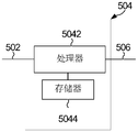
- the processing apparatus includes:
- a processor for executing the program stored by the memory, the processing device for implementing various implementations of the encoding method of the first aspect or the second aspect or the third aspect when the program is executed example.
- the above memory may be a physically separate unit or may be integrated with the processor.
- Yet another aspect of an embodiment of the present application further provides a communication device for implementing a function of encoding, the communication device comprising: the processing device described in the various aspects above, and a transceiver.
- the transceiver is configured to send a rate matched sequence.
- Yet another aspect of an embodiment of the present application also provides a computer readable storage medium having stored therein instructions that, when run on a computer, cause the computer to perform the methods described in the above aspects .
- Yet another aspect of an embodiment of the present application also provides a computer program product comprising instructions that, when executed on a computer, cause the computer to perform the methods described in the various aspects above.
- 1 is a schematic structural diagram of a wireless communication system
- FIG. 2 is a schematic diagram of a basic flow of wireless communication
- FIG. 3 is a schematic flow chart of coding a cascading cyclic redundancy check bit of a Polar code
- FIG. 4 is a schematic diagram of a data structure of a cascading cyclic redundancy check bit of a Polar code
- FIG. 5 is a schematic diagram of a data structure of a policing check freeze bit of a Polar code
- FIG. 6 is a schematic diagram of a PC-Polar SCL decoding process
- Figure 7 (a) is a schematic flow chart of CA-Polar and PC-Polar cascade coding
- FIG. 7(b) is a schematic flowchart of decoding in a manner in which CA-Polar and PC-Polar are cascaded;
- FIG. 8 is a schematic flowchart diagram of an embodiment of an encoding method provided by the present application.
- FIG. 9 is a schematic diagram of a process of extracting Z bits to be encoded from a bit sequence to be encoded in an embodiment of the encoding method provided by the present application.
- FIG. 10 is a schematic flowchart diagram of another embodiment of an encoding method provided by the present application.
- FIG. 11 is a schematic flowchart diagram of another embodiment of an encoding method provided by the present application.
- FIG. 12 is a schematic structural diagram of a processing apparatus for encoding provided by the present application.
- FIG. 13 is a schematic structural diagram of another processing apparatus for encoding provided by the present application.
- FIG. 14 is a schematic structural diagram of still another processing apparatus for encoding provided by the present application.
- 15 is a schematic structural diagram of a communication device provided by the present application.
- FIG. 16 is a schematic structural diagram of a terminal provided by the present application.
- the wireless communication system may include at least one network device that communicates with one or more terminals.
- the network device may be a base station, or may be a device integrated with a base station controller, or may be another device having similar communication functions.
- the wireless communication system mentioned in the embodiments of the present application includes, but is not limited to, a narrowband Internet of Things system (English: Narrow Band-Internet of Things, referred to as NB-IoT), and a global mobile communication system (English: Global System) For Mobile Communications (GSM), Enhanced Data Rate for GSM Evolution (EDGE), Wideband Code Division Multiple Access (WCDMA) , Code Division Multiple Access (English: Code Division Multiple Access, CDMA2000 for short), Time Division-Synchronization Code Division Multiple Access (TD-SCDMA), Long Term Evolution ( English: Long Term Evolution (LTE), the three major application scenarios of next-generation 5G mobile communication systems, eMBB, URLLC and eMTC, or new communication systems that will appear in the future.
- GSM Global System
- EDGE Enhanced Data Rate for GSM Evolution
- WCDMA Wideband Code Division Multiple Access
- CDMA2000 Code Division Multiple Access
- TD-SCDMA Time Division-Synchronization Code Division Multiple Access
- LTE Long Term Evolution
- the terminals involved in the embodiments of the present application may include various handheld devices having wireless communication functions, in-vehicle devices, wearable devices, computing devices, or other processing devices connected to a wireless modem.
- the terminal may be an MS (English: Mobile Station), a subscriber unit (English: subscriber unit), a cellular phone (English: cellular phone), a smart phone (English: smart phone), a wireless data card, a personal digital assistant (English: Personal Digital Assistant, referred to as: PDA) computer, tablet computer, wireless modem (English: modem), handheld device (English: handset), laptop (English: laptop computer), machine type communication (English: Machine Type Communication , referred to as: MTC) terminal.
- MS International: Mobile Station
- PDA Personal Digital Assistant
- PDA Personal Digital Assistant
- tablet computer tablet computer
- wireless modem English: modem
- handheld device English: handset
- laptop English: laptop computer
- machine type communication English: Machine Type Communication
- the network device in FIG. 1 communicates with the terminal using wireless technology.
- the network device sends a signal, it is the transmitting end.
- the network device receives the signal, it is the receiving end; the terminal is also the same.
- the terminal sends a signal, it is the transmitting end.
- the terminal receives the signal, it is the receiving end.
- . 2 is a basic flow of communication using wireless technology.
- the source of the transmitting end is sequentially transmitted on the channel after source coding, channel coding, rate matching, and modulation. After receiving the signal, the receiving end undergoes demodulation, de-rate matching, and A channel is obtained after channel decoding and source decoding.
- Channel codec is one of the core technologies in the field of wireless communication, and its performance improvement will directly improve network coverage and user transmission rate.
- the polarization code is a channel coding technology that can theoretically prove to reach the Shannon limit and has practical linear complexity coding and decoding capabilities.
- the core of the polarization code structure is the processing of "channel polarization".
- the coding method is used to make each subchannel exhibit different reliability.
- some channels will tend to be close to the capacity.
- the no-noise channel of 1 and the other part of the channel tend to be a full-noise channel with a capacity close to zero, and the information is directly transmitted on a channel having a capacity close to 1 to approximate the channel capacity.
- the encoding strategy of the Polar code is the characteristic that applies this phenomenon.
- the non-noise channel is used to transmit the useful information of the user, and the full-noise channel transmits the agreed information or does not transmit the information.
- the Polar code is also a linear block code whose encoding matrix is G N and the encoding process is among them Is a binary line vector of length N (ie code length); G N is an N ⁇ N matrix, and Defined as the Kronecker product of log 2 N matrices F 2 . Above matrix
- GN.(A) is a collection in GN.
- the sub-matrices obtained from those rows corresponding to the index, GN.(AC) is the set in GN.
- the encoded output of the Polar code can be simplified to:
- indicates the number of elements in the collection, and K is the size of the information block.
- the construction process of the Polar code is a collection
- the selection process determines the performance of the Polar code.
- the construction process of the Polar code is generally: determining that there are N polarized channels in total according to the length N of the mother code, respectively corresponding to N rows of the coding matrix, calculating the reliability of the polarized channel, and the first K polarizations with higher reliability.
- Channel index as a collection Element
- the index corresponding to the remaining (NK) polarized channels as the index set of fixed bits Elements. set Determine the location of the information bits, the collection The position of the fixed bit is determined.
- FIG. 2 is a schematic diagram of a basic flow of a commonly used wireless communication.
- the source is sequentially transmitted after source coding, channel coding, and digital modulation.
- digital demodulation, channel decoding, and source decoding are sequentially outputted to the sink.
- the channel coding can use a Polar code, and in the case of channel decoding, SC decoding, SCL decoding, etc. can be used.
- many techniques have been proposed to improve on the basis of the Polar code, such as CA-Polar code, PC-Polar code, CA-PC-Polar and the like.
- CA-Polar the encoding method of the Polar code cascading Cyclic Redundancy Check bit is referred to as CA-Polar.
- CRC check Cyclic Redundancy Check
- CA-SCL CRC-Aided Successive Cancellation List
- the construction process of the CA-Polar code includes a process of determining the position of the information bits. Assuming that the information block size is Kinfo, the CRC length is Kcrc, and the encoded mother code length is N, only Kinfo+Kcrc with the highest reliability is selected as the information bits from the N polarized channels, and the rest are used as static freeze bits. (or called a frozen bit).
- the information block is first CRC-encoded, then the CRC-encoded bits are mapped to the information bits, the static freeze bits are placed at the fixed values agreed upon at both ends, and finally Arikan Polar coding is performed.
- CA-Polar coding block The CRC bits may be concatenated at the front end or the back end of the information block or distributed inside the information block.
- the information block and CRC bits are unknown, and are decoded according to normal SCL.
- L path-expanded width
- candidate decoding results are obtained, the candidate decoding results including information blocks and CRC bits.
- a CRC check is performed on each candidate decoding result, and if the check passes, the information block of the path is output as a decoding. Otherwise, the information block of the candidate decoding result of the path with the smallest PM is used as the decoding output, or the decoding failure is directly indicated.
- CA-Polar can achieve a lower Block Error Rate (BLER) than SCL.
- the CRC bits are treated as information bits and are used to select the path only at the end of SCL decoding.
- the Polar code cascading check (Parity-check) bit referred to as PC-Polar
- PC-Polar is another cascading code method for improving the performance of the Polar code.
- the main idea of PC-Polar is to select some parity bits (Parity-check-frozen), also known as Dynamic Frozen bits or check freeze bits, which are distributed into information blocks, and the value of the check bits is determined by The previous information bits are determined according to the check equation.
- PC-Polar mainly enhances the performance of Polar code by increasing the minimum code distance of the Polar code by PC coding the information block.
- the structure of PC-Polar mainly includes two points, one is the position of the check bit, usually needs to be located in a highly reliable polarized channel; the other is the check equation, that is, which check bits are determined by the preceding information bits.
- the encoding process of the PC-Polar code is similar to that of CA-Polar, including PC encoding and Arikan encoding.
- the PC encoding determines the value of the check bit according to the check equation and the value of the information block, and the static freeze bit is still placed. The value known at both ends of the transceiver.
- the decoding algorithm of PC-Polar is based on the SCL decoding algorithm.
- the processing of information bits and static freeze bits is the same as that of the SCL decoding algorithm.
- the difference is the processing of dynamic freeze bits. Since the dynamic freeze bit is not an unknown information bit but is determined by its preceding information bits, its processing is similar to a static freeze bit, except that the value of the dynamic freeze bit is calculated from the previously decoded information bits.
- the dynamic freeze bit actually assists in the verification of the information bit decoding result due to the correlation with the previous information bits.
- the PC-SCL decodes the path that ultimately outputs the smallest PM.
- the arrow between the dynamic freeze bit and the information bit indicates the check relationship between the dynamic freeze bit and the information bit.
- the value of the decoded information bit is calculated according to the check relationship to obtain the value of the dynamic freeze bit, and is used for decoding.
- the location of the dynamic freeze bits in PC-Polar plays an important role in performance and needs to be carefully selected during construction.
- Figure 7 (a) is a schematic flow chart of the commonly used CA-Polar and PC-Polar cascade coding, as shown in Figure 7 (a), (1) the bit sequence a 0 , a 1 , a 2 , .. to be encoded. , a A-1 first performs Cyclic Redundancy Check (CRC) encoding to obtain b0, b1, ...
- CRC Cyclic Redundancy Check
- the implementation of the Polar coding method with a cascaded CRC is to first determine the location of the information bits, the static freeze bits, and the check bits. Then, the bit sequence to be encoded is subjected to CRC encoding, that is, CRC calculation is performed (where A represents the length of the information bit, B represents the sum of the lengths of the information bits and the CRC check bits), and the input of the CRC calculation is the information bit a 0 . a 1 , a 2 , ..., a A-1 , the generated check bits are p 0 , p 1 , p 2 , ..., p Kcrc-1 .
- the CRC is encoded in the following manner to obtain b0, b1, ... bB-1, where
- the values of the information bits, the static freeze bits, and the check freeze bits are set in the CRC code sequences b0, b1, ... bB-1 obtained by the CRC coding.
- the information bit, the static freeze bit, and the value of the check freeze bit may be set in the following manner to obtain a sequence c 0 , c 1 , . . . , c C-1 (C indicates that the information bit is set, the static freeze bit is set, and The length of the sequence after checking the value of the frozen bit, that is, C is equal to the length of the mother code N), where
- rate matching is performed.
- the sequence that is not transmitted is removed from the sequence of d 0 , d 1 , d 2 ..., d D-1 to obtain transmission sequences e 0 , e 1 , e 2 ..., e E-1 , and E represents rate matching.
- the length of the sequence ie the code length. After the encoding is completed, the obtained transmission sequence can be transmitted to the receiving device.
- CRC encoding and PC encoding checking the frozen bit value and the determination of the check equation
- FIG. 7(b) is a schematic diagram of decoding of commonly used CA-Polar and PC-Polar concatenated coding.
- SCL decodes the Polar code and outputs L surviving paths (L is One parameter), then perform CRC check on these surviving paths, and select the path through which the CRC passes as the decoded output.
- L is One parameter
- the application of the coding method and the decoding method provided by the present application may be a network device or a terminal in the process of information interaction between the network device and the terminal; correspondingly, the decoding side may be the terminal. It can be a network device. Optionally, it can also be applied to the information interaction process between the terminals, which is not limited in this application.
- the auxiliary bits refer to bits that are dynamically generated at the encoding end and used to assist decoding at the decoding end, and the auxiliary decoding refers to error correction, error detection, or Help to determine whether to terminate decoding in advance.
- the auxiliary bits may include check freeze bits (which may also be referred to as freeze check bits, PC-frozen bits, Parity-check-frozen bits, pre-frozen bits, parity bits, Dynamic Frozen bits, or PC schools) A bit check), at least one of a HASH check bit, a distributed CRC bit, and a CRC check bit.
- FIG. 8 is a schematic flowchart of an embodiment of an encoding method provided by the present application. As shown in FIG. 8 , the encoding method specifically includes:
- S101 Receive a bit sequence to be encoded.
- S102 Initialize a state space value in the state space module, and obtain a set of Z to-be-coded bits consisting of Z information bits from the bit sequence to be encoded;
- step S105 encode the Z to-be-coded bits obtained in step S102, where there are auxiliary bits in the bit sequence to be encoded, where each auxiliary information bit is located between the information bits of the Z information bits, And in the case that the auxiliary bit is located between the Z information bits and the next information bit, the value obtained from the new state space value is assigned to the auxiliary bit; Then performing step S106;
- S106 Acquire, from the bit sequence to be encoded, a next group of Z to be coded bits consisting of Z information bits after the group of Z to be coded bits, and the next group of Z to be coded bits and The set of Z to be coded bits are adjacent, and the next group of Z code to be coded is used as the input of the step S104, and the step S104 is performed, and the step S105 is performed, and the loop is continued until the The next set of Z to-be-coded bits is the last bit to be encoded in the bit sequence to be encoded.
- Z information bits are processed each time until the information bits in the bit sequence to be encoded are processed.
- the auxiliary bit coding is performed on the encoding end, so that the decoding end can perform auxiliary decoding operations such as error correction, error detection, or early stop on the encoded bit sequence by using the auxiliary bits.
- the block processing is used to perform auxiliary bit coding, which is convenient for hardware implementation, and can effectively improve coding efficiency and throughput.
- the next group after acquiring the set of Z to-be-coded bits from the bit sequence to be encoded is composed of Z information bits.
- Z coded bits, the next group of Z coded bits consisting of Z information bits and the set of Z code bits to be coded by Z information bits are adjacent to each other: Shown in Figure 9, a series of bit sequences to be encoded, where F represents a frozen bit, I represents an information bit, and PF represents an auxiliary bit.
- the preceding and following order between the Z information bits in the acquired Z coded bits and the Z information bits are in the The order in the encoded bit sequence is consistent.
- FIG. 9 shows a series of bit sequences to be encoded, where F represents a frozen bit, I represents an information bit, and PF represents an auxiliary bit.
- F represents a frozen bit
- I represents an information bit
- PF represents an auxiliary bit.
- Z 2
- the case where Z is 2 information bits are successively extracted from the bit sequence to be encoded.
- the case where the auxiliary bit is located between the information bits of the Z information bits in the bit sequence to be encoded means: as shown in FIG.
- auxiliary bit between the two information bits is skipped, and a value obtained from the new state space value is assigned to the one auxiliary bit. If there are two or more auxiliary bits between the two information bits, the value to be obtained from the new state space value is assigned to the two or more auxiliary bits.
- the case where the auxiliary bit is located between the Z information bits and the next information bit in the bit sequence to be encoded means that two pieces of information are obtained from the bit sequence to be encoded, as shown in FIG. After the bit, when two information bits are acquired from the bit sequence to be encoded, one auxiliary bit is skipped, and a value obtained from the new state space value is assigned to the one auxiliary bit. If there are two or more auxiliary bits between the information bits acquired twice, then the values to be obtained from the new state space values are assigned to the two or more auxiliary bits.
- obtaining a value from the new state space value is assigned to the auxiliary bit, including: respectively from the new The obtained value in the state space value is assigned to the auxiliary bit located between each of the Z information bits, and the auxiliary bit located between the Z information bits and the next information bit.
- a value assigned to an auxiliary bit between each of the Z information bits, and a value assigned to an auxiliary bit located between the Z information bits and a next information bit may be from the new The same location in the state space value is obtained, or is obtained from a different location in the new state space value.
- the values assigned to the two auxiliary bits can be the same or different.
- the next group of Z to be coded bits is the last bit to be encoded in the bit sequence to be encoded, which means:
- the bit sequence to be encoded finally has less than or equal to Z information bits.
- the insufficient portion is filled with a fixed value of 0 or 1.
- step S104 may be performed before step S105.
- the method further includes:
- the coding mode used in the precoding is consistent with the coding mode used in the coding described in the step S105, and the precoding is the preprocessing process of the coding described in the step S105.
- the pre-coded result may refer to a pre-encoded value
- the pre-encoded value is stored as an index value in the index module.
- the index values in the index module can be stored in the form of an index table.
- the index value may be stored in the index module in an offline storage manner.
- the coding mode of the coding in the step S105 can be regarded as the target coding method of the coding method embodiment, that is, the coding mode of the coding in the step S105 can be considered as the implementation of the coding method.
- the encoding in the embodiment of the encoding method shown in FIG. 8, in the step S105, in the step of encoding the Z to-be-coded bits acquired in the step S102, the encoding refers to:
- the coding of the coding mode or the coding of the information digest coding method or the coding of the linear operation mode is checked.
- the code for checking the coding mode may be CRC coding or PC coding.
- the encoding of the message digest encoding method may be HASH (Hash) encoding or the like.
- the coding of the linear operation mode may be the coding using the coding matrix.
- the step S104 according to the value in the Z to-be-coded bits acquired in the step S102, and the state in the state space module.
- the spatial value is obtained from the index module, including:
- the operation of performing the operation according to the index value and the state space value includes:
- the index value and the state space value are subjected to bitwise logical operations.
- the specific bitwise logical operation mode may be a bitwise exclusive OR operation, or a bitwise AND operation, a bitwise OR operation, or a bitwise AND non-operation.
- performing the bitwise logical operation on the index value and the state space value may be: performing a bitwise logical operation on the index value and a low Z bit of the state space value.
- the operations of performing operations according to the index value and the state space value include:
- the index value and the state space value are subjected to a bitwise exclusive OR (XOR) operation.
- the step S104 according to the value in the Z to-be-coded bits acquired in the step S102, and the state in the state space module.
- the spatial value is obtained from the index module, including:
- step S1041 cyclically shift the state space value by Z bits in a fixed direction (for example, to the left or the right), and then, the lower Z bits of the state space value are compared with the location obtained in step S102.
- the values of the Z bits to be encoded are operated to obtain an index ID, and the index value stored in the index module is obtained by the index ID.
- the operation of performing the operation according to the index value and the state space value includes:
- S1042 Perform bitwise logical operations on the index value and the state space value. For example, the index value is subjected to a bitwise logical operation with the lower Z bits of the state space value.
- the state space module may specifically be a CRC register group.
- the storage space of the CRC register group is determined.
- the storage space of the CRC register group can be twice the length of the CRC. If the length of the CRC is Z bits, the storage space of the CRC register group. It can be 2Z bits and can process Z bits to be encoded at a time.
- the corresponding index value is obtained from the index module according to the value in the Z to-be-coded bits acquired in the step S102 and the state space value in the state space module, and include:
- the operation of performing the operation according to the index value and the state space value includes:
- S1044 cyclically shift all the bits in the CRC register group by Z bits in a fixed direction (for example, left or right), and then perform an exclusive OR operation on the index value with the lower Z bits of the CRC register group to obtain an XOR operation.
- the new state space value for example, left or right
- the auxiliary bit refers to a PC check bit.
- FIG. 10 is a schematic flowchart of another embodiment of an encoding method provided by the present application. As shown in FIG. 10, the encoding method specifically includes:
- S201 Receive a bit sequence to be encoded.
- S202 Initialize the state space value in the state space module, and obtain a set of Z to be encoded bits composed of information bits and auxiliary bits from the bit sequence to be encoded, and then perform step S203;
- step S203 The position of the auxiliary bit in the Z to be encoded bits is set to a fixed value, and then step S204 is performed;
- S206 Acquire, from the bit sequence to be encoded, a next set of Z to-be-coded bits consisting of information bits and auxiliary bits after the set of Z to-be-coded bits, the next group of Z to-be-coded bits Adjacent to the set of Z to-be-coded bits, and the next set of Z to-be-coded bits as an input of the step S203, and performing the step S203, the step S204, and the step S205 And continuously looping until the next set of Z to-be-coded bits is the last bit to be encoded in the bit sequence to be encoded.
- the Z bits to be encoded each time include both information bits and auxiliary bits, and are consecutive Extracting the information bits and the auxiliary bits in the bit sequence to be encoded until the information bits and the auxiliary bits in the bit sequence to be encoded are processed.
- the auxiliary bit coding is performed on the encoding end, so that the decoding end can perform auxiliary decoding operations such as error correction, error detection, or early stop on the encoded bit sequence by using the auxiliary bit.
- the block processing is used to perform auxiliary bit coding, which is convenient for hardware implementation, and can effectively improve coding efficiency and throughput.
- the preceding and succeeding order between the information bits and the auxiliary bits in the acquired Z to-be-coded bits and the information bits and the The order of the auxiliary bits in the bit sequence to be encoded is consistent. Specifically, as shown in FIG. 9, in the case where Z is 4, the information bits and the auxiliary bits are successively extracted from the bit sequence to be encoded.
- the next group of information bits and after the set of Z to-be-coded bits are obtained from the bit sequence to be encoded.
- the Z bits to be encoded formed by the auxiliary bits, the next group of Z to be coded bits being adjacent to the group of Z to be coded bits, as shown in FIG.
- the next group of Z to be coded bits is the last bit to be encoded in the bit sequence to be encoded, which means:
- the total number of information bits and auxiliary bits in the last remaining bits of the bit sequence to be encoded is equal to Z or less than Z.
- the insufficient portion is filled with a fixed value of 0 or 1.
- step S203 the value of the position of the information bit does not need to be changed.
- step S204 may be performed before step S205.
- the method further includes:
- the coding mode used in the precoding is consistent with the coding mode used in the coding described in the step S205, and the precoding is the preprocessing process of the coding described in the step S205.
- the pre-coded result may refer to a pre-encoded value
- the pre-encoded value is stored as an index value in the index module.
- the index values in the index module can be stored in the form of an index table.
- the index value may be stored in the index module in an offline storage manner.
- the precoding is processed for Z bits to be encoded that have not been processed in step S203.
- the encoding mode of the encoding in the step S205 can be regarded as the target encoding method of the encoding method embodiment, that is, the encoding mode of the encoding described in the step S205 can be considered as the embodiment of the encoding method.
- the encoding in the step S205, in the step of performing the encoding of the Z to-be-coded bits output after step S203, the encoding refers to: Coding of coding methods or coding of information digest coding or coding of linear operation.
- the code for checking the coding mode may be CRC coding or PC coding.
- the encoding of the message digest encoding method may be HASH (Hash) encoding or the like.
- the coding of the linear operation mode may be the coding using the coding matrix.
- the value in the Z to-be-coded bits output after the step S203 is performed, and the state space in the state space module.
- the corresponding index value is obtained from the index module, including:
- the operation of performing the operation according to the index value and the state space value includes:
- the index value and the state space value are subjected to bitwise logical operations.
- the specific bitwise logical operation mode may be a bitwise exclusive OR operation, or a bitwise AND operation, a bitwise OR operation, or a bitwise AND non-operation.
- performing the bitwise logical operation on the index value and the state space value may be: performing a bitwise logical operation on the index value and a low Z bit of the state space value.
- the operations of performing operations according to the index value and the state space value include:
- the index value and the state space value are subjected to a bitwise exclusive OR (XOR) operation.
- the value in the Z to-be-coded bits output after the step S203 is performed, and the state space in the state space module.
- the corresponding index value is obtained from the index module, including:
- S2041 cyclically shift the state space value by Z bits in a fixed direction (for example, left or right), and then output the lower Z bits of the state space value to the output after performing step S203.
- the values of the Z to-be-coded bits are operated to obtain an index ID, and the index value stored in the index module is obtained by the index ID.
- the operation of performing the operation according to the index value and the state space value includes:
- S2042 Perform bitwise logical operations on the index value and the state space value. For example, the index value is subjected to a bitwise logical operation with the lower Z bits of the state space value.
- the state space module may specifically be a CRC register group.
- the storage space of the CRC register group is determined.
- the storage space of the CRC register group can be twice the length of the CRC. If the length of the CRC is Z bits, the storage space of the CRC register group. It can be 2Z bits and can process Z bits to be encoded at a time.
- the corresponding index value is obtained from the index module according to the value of the Z code to be encoded and the state space value in the state space module, which may be included in the step S203.
- the operation of performing the operation according to the index value and the state space value includes:
- S2044 cyclically shifting all the bits in the CRC register group by Z bits in a fixed direction (for example, to the left or right), and then performing an exclusive OR operation on the index value with the lower Z bits of the CRC register group to obtain an XOR operation.
- the new state space value for example, to the left or right
- the auxiliary bit refers to a PC check bit.
- FIG. 11 is a schematic flowchart of another embodiment of an encoding method provided by the present application. As shown in FIG. 11, the encoding method specifically includes:
- S301 Receive a bit sequence to be encoded.
- S302 Initialize the state space value in the state space module, and obtain a set of adjacent Z code to be encoded bits from the bit sequence to be encoded, and then perform step S303;
- the Z to-be-coded bits include at least one of information bits, freeze bits, and auxiliary bits.
- the Z to-be-coded bits include auxiliary bits, set the position of the auxiliary bits to a fixed value, in the case where the Z bits to be encoded include a frozen bit, the position of the frozen bit is set to a fixed value, and then step S304 is performed;
- S304 Obtain a corresponding index value from the index module according to the value in the Z to-be-coded bits outputted after performing step S303, and the state space value in the state space module, according to the index value and the The state space value is operated to obtain a new state space value, and the state space value in the state space module is updated to the new state space value;
- the bits and the auxiliary bits are frozen, and Z bits are successively extracted from the bit sequence to be encoded for processing. Until the bits in the bit sequence to be encoded are processed.
- the Z bits to be encoded may include one or more of the information bits, the freeze bits, and the auxiliary bits.
- the auxiliary bit coding is performed on the encoding end, so that the decoding end can perform auxiliary decoding operations such as error correction, error detection, or early stop on the encoded bit sequence by using the auxiliary bit.
- the block processing is used to perform auxiliary bit coding, which is convenient for hardware implementation, and can effectively improve coding efficiency and throughput.
- the information bits in the acquired Z to-be-coded bits, the preceding and succeeding order between the auxiliary bits and the frozen bits, and the information Bits, the auxiliary bits and the frozen bits are consistent in the order of the bit sequences to be encoded.
- the information bits, the auxiliary bits and the frozen bits are successively extracted from the bit sequence to be encoded.
- the next set of adjacent Z code to be coded bits is the last bit to be coded in the bit sequence to be encoded is Means:
- the bit sequence to be encoded finally has less than or equal to Z bits to be encoded, and in the case that there are not enough Z bits to be encoded at the end of the bit sequence to be encoded, the insufficient portion is filled with a fixed value. 0 or 1.
- the position of the frozen bit is set to a fixed value, wherein the fixed value refers to an encoding end (or an encoding side). And fixed values agreed with the decoding end (or decoding side).
- step S303 the value of the position of the information bit does not need to be changed.
- step S304 may be performed before step S305.
- the position of the auxiliary bit is set to the encoding end (or encoding side) and the decoding end. (or the decoding side) the agreed value may be 0 or 1 .
- the transmitting device encodes the bit sequence to be encoded to obtain an encoded bit sequence, where the encoded bit sequence includes information bits, frozen bits, and auxiliary bits, wherein the auxiliary bits are included.
- the value is obtained by the state space value.
- Z is an even number greater than zero.
- the form of the state space module may specifically be a register, such as a register group.
- the values in the state space module are initialized: the encoding side (or encoding side) and the translation The agreed value between the code side (or the decoding side).
- the initialized value may be all "0", or any fixed sequence agreed upon by the encoding side and the decoding side.
- the state space module may be implemented by a register group, and when the state of the register group is initialized to all 1, the value is obtained from the new state space value in steps S105, S205, and S305. In the operation of the auxiliary bit, the new state space value should be inverted, and then the value of at least one of the new state space values is assigned to the auxiliary bit.
- the value assignment is obtained from the new state space value.
- the step of describing the auxiliary bits may include assigning a value of at least one of the new state space values to the auxiliary bits.
- the steps S105, S205, and S305 are performed multiple times for different Z code-coded bits, multiple times from the
- the step of obtaining a value in the new state space value to the auxiliary bit may include: assigning a value to the auxiliary bit from a fixed position of the state space module each time; or adopting a rotation rotation manner, according to a fixed direction, Starting from a certain position, successively selecting a value in the state space module to assign the value to the auxiliary bit; or adopting some pseudo-random manner, selecting a value from the state space module to assign the auxiliary bit; or adopting a certain function (e.g., a function of the relationship between the size of the storage space of the state space module and the sequence number of the auxiliary bits), the selected value is assigned to the auxiliary bit at the calculated position in the state space module.
- a certain function e.g., a function of the relationship between the size of the storage space of the state space module and the sequence number of the auxiliary bits
- the method further includes:
- the coding mode used in the precoding is consistent with the coding mode used in the coding described in the step S305, and the precoding is the preprocessing process of the coding described in the step S305.
- the pre-coded result may refer to a pre-encoded value
- the pre-encoded value is stored as an index value in the index module.
- the index values in the index module can be stored in the form of an index table.
- the index value may be stored in the index module in an offline storage manner.
- the precoding is processed for the Z to be encoded bits that have not been processed in step S303.
- the encoding mode of the encoding in the step S305 can be regarded as the target encoding method of the encoding method embodiment, that is, the encoding mode of the encoding described in the step S305 can be considered as the embodiment of the encoding method.
- the encoding in the embodiment of the encoding method shown in FIG. 11, in the step S305, in the step of performing encoding of the Z to-be-coded bits output after step S303, the encoding refers to: Coding of coding methods or coding of information digest coding or coding of linear operation.
- the code for checking the coding mode may be CRC coding or PC coding.
- the encoding of the message digest encoding method may be HASH (Hash) encoding or the like.
- the coding of the linear operation mode may be the coding using the coding matrix.
- the value in the Z to-be-coded bits output after the step S303 is performed, and the state space in the state space module.
- the corresponding index value is obtained from the index module, including:
- the operation of performing the operation according to the index value and the state space value includes:
- the index value and the state space value are subjected to bitwise logical operations.
- the specific bitwise logical operation mode may be a bitwise exclusive OR operation, or a bitwise AND operation, a bitwise OR operation, or a bitwise AND non-operation.
- the bitwise logical operation of the index value and the state space value may be: performing a bitwise logical operation on the index value and the low Z bit of the state space value.
- the operations of performing operations according to the index value and the state space value include:
- the index value and the state space value are subjected to a bitwise exclusive OR (XOR) operation.
- the value in the Z to-be-coded bits output after the step S303 is performed, and the state space in the state space module.
- the corresponding index value is obtained from the index module, including:
- S3041 cyclically shift the state space value by Z bits in a fixed direction (for example, leftward or rightward), and then output the lower Z bits of the state space value to the output after performing step S303.
- the values of the Z to-be-coded bits are operated to obtain an index ID, and the index value stored in the index module is obtained by the index ID.
- the operation of performing the operation according to the index value and the state space value includes:
- the state space module may specifically be a CRC register group. According to the type of CRC used in the encoding, the storage space of the CRC register group is determined. Generally speaking, the storage space of the CRC register group can be twice the length of the CRC. If the length of the CRC is Z bits, the storage space of the CRC register group. It can be 2Z bits and can process Z bits to be encoded at a time.
- the corresponding index value is obtained from the index module according to the value of the Z code to be encoded and the state space value in the state space module, which may be included in the step S303.
- the operation of performing the operation according to the index value and the state space value includes:
- S3044 cyclically shift all the bits in the CRC register group by Z bits in a fixed direction (for example, left or right), and then perform an exclusive OR operation on the index value with the lower Z bits of the CRC register group to obtain an XOR operation.
- the new state space value for example, left or right
- the auxiliary bit in the process of obtaining a value from the new state space value assigned to the auxiliary bit, refers to a PC check bit.
- the method further includes:
- the last bit to be encoded in the bit sequence to be encoded is used as an input of the step S303, and the step S303 is performed, and after the step S304 and the step S305, the obtained state space module is obtained.
- the state space value is used as the CRC check bit and is CRC encoded.
- the auxiliary bit in the process of obtaining a value from the new state space value and assigning the auxiliary bit, the auxiliary bit may refer to a PC check. Bit.
- the foregoing embodiment of the present application can implement simultaneous coding of different types of auxiliary bits by the system, reduce hardware overhead, and improve coding efficiency.
- the method further includes:
- S307 Perform polarization coding and rate matching on the encoded bit sequence to obtain a rate matched sequence to be transmitted.
- S308 Send the sequence after the rate matching.
- the above-described steps S307 and S308 may be performed after the execution of the S3060.
- the state space value is generated using a 17-bit polynomial, and the state space value is in a state space module of 16-bit (double-byte) bits. In the process of updating the state space value, it is updated in units of 8 bits (in the case where Z in the above embodiment is 8), that is, in units of one byte.
- the update process for state space values includes:
- the state space value in the state space module is initialized to all "0", or any fixed sequence agreed upon by the encoding side and the decoding side.
- the state space value in the state space module is rotated left by 8 bits and the state space value is saved.
- the lower 8 bits of the state space value in the state space module are operated with the 8 bits to be encoded to obtain a corresponding index value in the index table.
- the index value in the index table is operated with the state space value in the state space module to obtain a new state space value, and the state space value in the state space module is updated to the new state space value.
- the register is a 16-bit register, and the result of the left shift or the right shift of the 8 bits is the same, and the register high 8 is exchanged with the lower 8 bits.
- PC encoding is performed while performing CRC encoding.
- Z is 8, and the state space module is a CRC register set.
- This example includes the following steps:
- the CRC value corresponding to all possible permutation combinations of the 8 bits of the bit to be encoded is made into an index table, and the index table is stored offline.
- the CRC register set is shifted 8 bits to the left and saved to the CRC register set.
- the upper 8 bits of the original CRC register group before the left shift of 8 bits are XORed with the 8 bits of the bits to be encoded to obtain an index to the table.
- the table value pointed to by the index is XORed with the CRC register set to obtain a new state space value.
- the obtained state space value is used as a CRC bit, and CRC coding is performed.
- processing device 504 for encoding, which may be implemented by hardware or by software.
- Processing device 504 includes:
- An input interface circuit 5142 configured to receive a bit sequence to be encoded
- a logic circuit 5144 configured to initialize a state space value in the state space module, and obtain a set of Z to-be-coded bits consisting of Z information bits from the bit sequence to be encoded; according to the obtained Z a bit to be coded, a new state space value is obtained, and a value is assigned to the auxiliary bit.
- a new state space value is obtained, and the auxiliary bit is assigned: according to the obtained a value of the Z to be coded bits, and a state space value in the state space module, obtaining a corresponding index value from the index module, and performing an operation according to the index value and the state space value to obtain a new state space a value, and updating the state space value in the state space module to the new state space value; encoding the obtained Z code to be encoded, and assisting in the bit sequence to be encoded Where the bit is located between each of the Z information bits, and wherein the auxiliary bit is located in the Z bit to be encoded and the next information bit In the case of a new state space value, the value is assigned to the auxiliary bit; the next group after the group of Z code to be encoded is obtained from the bit sequence to be encoded is Z.
- Z bits to be encoded consisting of information bits, the next group of Z coded bits being adjacent to the group of Z bits to be coded, and obtaining a new state according to the next group of Z bits to be coded
- the spatial value, and the auxiliary bit is assigned, continues to loop until the next set of Z to-be-coded bits is the last bit to be encoded in the bit sequence to be encoded.
- the processing device may be a chip or an integrated circuit.
- the processing device shown in FIG. 12 provided by the embodiment of the present invention can be used to execute various embodiments of the encoding method shown in FIG. 8 or FIG. 10 or FIG. 11 , and the implementation principle and technical effects are similar.
- the processing apparatus shown in FIG. 12 provided by the embodiment of the present invention in the case of performing various embodiments of the encoding method shown in FIG. 8, the encoding shown in FIG.
- Various specific implementations of the method S101 in the method can also be used as various embodied implementations of the functions of the input interface circuit 5142 of the processing device shown in FIG.
- the various specific implementations of steps S102, S104, S105, S106, S3060, and S307 in the encoding method shown in FIG. 8 can also be used as the logic circuit 5144 of the processing device shown in FIG. 12, respectively.
- Various implementations of the functionality are examples of the functionality.
- the processing device shown in FIG. 12 provided by the embodiment of the present invention, in the case of performing various embodiments of the encoding method shown in FIG. 10,
- the input interface circuit 5142 is configured to receive a bit sequence to be encoded
- the logic circuit 5144 is configured to initialize a state space value in the state space module, and obtain a set of Z to-be-coded bits consisting of information bits and auxiliary bits from the bit sequence to be encoded, according to the acquired
- the Z bits to be encoded a new state space value is obtained, and the auxiliary bit is assigned.
- a new state space value is obtained, and the auxiliary bit is assigned.
- Positions of the auxiliary bits in the Z to-be-coded bits are set to a fixed value, and then the corresponding index is obtained from the index module according to the values in the Z to-be-coded bits and the state space value in the state space module.
- the Z bits to be encoded after the position of the auxiliary bit in the bit to be coded is set to a fixed value, and the value obtained from the new state space value is assigned to the Z bit to be coded.
- the auxiliary bit then acquiring, from the bit sequence to be encoded, the next set of Z to-be-coded bits consisting of information bits and auxiliary bits after the set of Z to-be-coded bits, the next set of Z
- the to-be-coded bits are adjacent to the set of Z to-be-coded bits, and according to the next set of Z to-be-coded bits, a new state space value is obtained, and the auxiliary bits are assigned, and the loop is continuously looped until the next A set of Z to-be-coded bits is the last bit to be encoded in the bit sequence to be encoded.
- step S201 in the encoding method shown in FIG. 10 can also be variously embodied as functions of the input interface circuit 5142 of the processing device shown in FIG. The way to achieve it.
- the various specific implementations of steps S202, S203, S204, S205, S206, S3060, and S307 in the encoding method shown in FIG. 10 can also be used as the logic circuit of the processing device shown in FIG. 12, respectively.
- the various implementations of the various features can also be variously embodied as functions of the input interface circuit 5142 of the processing device shown in FIG. The way to achieve it.
- steps S202, S203, S204, S205, S206, S3060, and S307 in the encoding method shown in FIG. 10 can also be used as the logic circuit of the processing device shown in FIG. 12, respectively.
- the processing device shown in FIG. 12 provided by the embodiment of the present invention is used in the case of performing various embodiments of the encoding method shown in FIG.
- the input interface circuit 5142 is configured to receive a bit sequence to be encoded
- the logic circuit 5144 is configured to initialize a state space value in the state space module, and obtain a set of adjacent Z code to be encoded bits from the bit sequence to be encoded, according to the obtained Z to be encoded Encoding bits, obtaining a new state space value, and assigning a value to the auxiliary bit, the obtaining a new state space value according to the obtained Z code to be encoded, and assigning the auxiliary bit to include: the Z bits to be coded Including at least one of information bits, freeze bits, and auxiliary bits, where the Z bits to be encoded include auxiliary bits, the position of the auxiliary bits is set to a fixed value, and the Z The coded bit includes a frozen bit, the position of the frozen bit is set to a fixed value, and then according to the value in the Z code to be encoded, and the state space value in the state space module, the index module Obtaining a corresponding index value, performing an operation according to the index value and the state space value, obtaining a new state space value, and updating the state space
- step S301 in the encoding method shown in FIG. 11 can also be used as various functions of the input interface circuit 5142 of the processing device shown in FIG. Concrete implementation.
- steps S302, S303, S304, S305, S306, S3060, and S307 in the encoding method shown in FIG. 11 can also be used as the logic circuit of the processing device shown in FIG. 12, respectively.
- the various implementations of the various features can also be used as the logic circuit of the processing device shown in FIG. 12, respectively.
- the processing device 504 When the processing device 504 is implemented in software, see FIG. 13, the processing device 504 includes:
- a memory 5044 configured to store a program
- a processor 5042 configured to execute the program stored by the memory, when the program is executed, the processing apparatus is configured to implement various implementations of the encoding method illustrated in FIG. 8 or FIG. 10 or FIG. example.
- the above memory 5044 may be a physically separate unit or may be integrated with the processor 5042, as shown in FIG.
- the communication device 500 includes: the processing device 504 in the foregoing embodiments, and a transceiver.
- the transceiver is configured to send a rate matched sequence.
- the above communication device may be a terminal or a network device.
- the terminal 600 may further include a power source 512 for providing power to various devices or circuits in the terminal; the terminal may further include an antenna 510 for transmitting the transceiver
- the output uplink data is transmitted through a wireless signal, or the received wireless signal is output to the transceiver.
- the terminal may further include one or more of an input unit 514, a display unit 516, an audio circuit 518, a camera 520, a sensor 522, and the like, and the audio circuit 518 may include Speaker 5182, microphone 5184, and the like.
- the above functions are implemented in the form of software and sold or used as stand-alone products, they can be stored in a computer readable storage medium.
- the part of the technical solution of the present application which contributes in essence or to the prior art, or part of the technical solution, may be embodied in the form of a software product stored in a storage medium.
- a number of instructions are included to cause a computer device (which may be a personal computer, server, or network device, etc.) to perform all or part of the steps of the methods described in various embodiments of the present application.
- the foregoing storage medium includes: a U disk, a mobile hard disk, a read-only memory (ROM), a random access memory (RAM), a magnetic disk, or an optical disk, and the like. .
Landscapes
- Engineering & Computer Science (AREA)
- Computer Networks & Wireless Communication (AREA)
- Signal Processing (AREA)
- Physics & Mathematics (AREA)
- Probability & Statistics with Applications (AREA)
- Theoretical Computer Science (AREA)
- Compression Or Coding Systems Of Tv Signals (AREA)
- Compression, Expansion, Code Conversion, And Decoders (AREA)
Abstract
本发明实施例公开了一种编码方法,该方法包括:根据获取的所述Z个待编码比特中的值,以及所述状态空间模块中的状态空间值,从索引模块中获取对应的索引值,根据所述索引值和所述状态空间值进行运算,得到新的状态空间值,对获取的所述Z个待编码比特进行编码,从所述新的状态空间值中获取数值赋给辅助比特。
Description
本申请要求于2017年5月2日提交中国专利局、申请号为201710301564.2、发明名称为“一种编码的方法和装置”的中国专利申请的优先权,其全部内容通过引用结合在本申请中。
本发明涉及通信技术领域,尤其涉及一种编码的方法和装置。
极化码(Polar Codes)是2008年提出的一种新型的信道编码方式。极化码基于信道极化(Channel Polarization)进行设计,是第一种能够通过严格的数学方法证明达到信道容量的构造性编码方案,Polar码是一种线性块码。
但是采用何种编码方式,能使得解码端在对编码后的比特序列进行译码的过程中起到辅助译码的作用,现有技术中还没有解决方案。
发明内容
本发明实施例提供了一种编码的方法和装置,用于解决如何通过编码,以使得解码端在对编码后的比特序列进行译码的过程中能够辅助译码的问题。
第一方面,本发明实施例提供一种编码方法,所述方法包括:
S101:接收待编码的比特序列;
S102:将状态空间模块中的状态空间值进行初始化,并从所述待编码的比特序列中获取一组由Z个信息比特组成的Z个待编码比特;
S104:根据所述步骤S102中获取的所述Z个待编码比特中的值,以及所述状态空间模块中的状态空间值,从索引模块中获取对应的索引值,根据所述索引值和所述状态空间值进行运算,得到新的状态空间值,并将所述状态空间模块中的状态空间值更新为所述新的状态空间值;
S105:对所述步骤S102中获取的所述Z个待编码比特进行编码,在所述待编码的比特序列中有辅助比特位于所述Z个信息比特中的各个信息比特之间的情况下,以及,在所述待编码的比特序列中有辅助比特位于所述Z个信息比特与下一个信息比特之间的情况下,从所述新的状态空间值中获取数值赋给所述辅助比特;然后执行步骤S106;
S106:从所述待编码的比特序列中获取所述一组Z个待编码比特之后的下一组由Z个信息比特组成的Z个待编码比特,所述下一组Z个待编码比特与所述一组Z个待编码比特相邻,并将所述下一组Z个待编码比特作为所述步骤S104的输入,并执行所述步骤S104, 及所述步骤S105,不断循环,直至所述下一组Z个待编码比特为所述待编码的比特序列中最后的待编码比特。
在上述编码方法的实施例中,通过在编码端进行辅助比特编码,使得解码端能够采用辅助比特对编码后的比特序列进行纠错、检错或者早停等辅助译码操作。并且由于每次针对Z个待编码比特进行编码,采用这种块处理的方式进行辅助比特编码,方便硬件实施,可以有效提升编码效率与吞吐量。
在第一方面的第一种可能的实现方式中,辅助比特是指在编码端动态生成的,并且在解码端用于辅助译码的比特,所述的辅助译码是指进行纠错、进行检错或帮助判断是否提前终止译码等。
结合第一方面或第一方面前述的各种可能的实现方式,在第二种可能的实现方式中,在所述步骤S102中,所述获取的Z个待编码比特中Z个信息比特之间的前后次序与所述Z个信息比特在所述待编码的比特序列中的前后次序是一致的。
结合第一方面或第一方面前述的各种可能的实现方式,在第三种可能的实现方式中,在所述待编码的比特序列中有辅助比特位于所述Z个信息比特中的各个信息比特之间的情况下,以及,在所述待编码的比特序列中有辅助比特位于所述Z个信息比特与下一个信息比特之间的情况下,从所述新的状态空间值中获取数值赋给所述辅助比特,包括:分别从所述新的状态空间值中获取数值赋给位于所述Z个信息比特中的各个信息比特之间的辅助比特,以及位于所述Z个信息比特与下一个信息比特之间的辅助比特。赋给所述Z个信息比特中的各个信息比特之间的辅助比特的数值,以及赋给位于所述Z个信息比特与下一个信息比特之间的辅助比特的数值,可以从所述新的状态空间值中的同一位置获取,或者是从所述新的状态空间值中的不同的位置获取。
结合第一方面或第一方面前述的各种可能的实现方式,在第四种可能的实现方式中,在所述步骤S106中,所述下一组Z个待编码比特为所述待编码的比特序列中最后的待编码比特是指:所述待编码的比特序列最后还剩下小于或等于Z个信息比特,在所述待编码的比特序列最后还剩下的信息比特不够Z个的情况下,将不足的部分填充固定值0或1。
结合第一方面或第一方面前述的各种可能的实现方式,在第五种可能的实现方式中,在所述步骤S104之前还包括:
对所述待编码的比特序列中的所述Z个待编码比特的2
z种排列组合进行预编码,将预编码后的结果作为索引值存储在所述索引模块中。所述预编码中所采用的编码方式与所述步骤S105中所述的编码中所采用的编码方式是一致的,所述预编码是所述步骤S105中所述的编码的预处理过程。
结合第一方面或第一方面前述的各种可能的实现方式,在第六种可能的实现方式中,在所述步骤S105中,对所述步骤S102中获取的所述Z个待编码比特进行编码的步骤中,所述的编码是指:检验编码方式的编码或信息摘要编码方式的编码或线性运算方式的编码。
结合第一方面或第一方面前述的各种可能的实现方式,在第七种可能的实现方式中,在所述步骤S104中,根据所述步骤S102中获取的所述Z个待编码比特中的值,以及所述状态空间模块中的状态空间值,从索引模块中获取对应的索引值,包括:
将所述状态空间值的低Z个比特位与所述步骤S102中获取的的所述Z个待编码比特中的值进行运算,得到索引ID,并通过该索引ID获得索引模块中存储的索引值。
结合第一方面或第一方面前述的各种可能的实现方式,在第八种可能的实现方式中,
在所述步骤S104中,根据所述索引值和所述状态空间值进行运算的操作,包括:
将所述索引值和所述状态空间值进行按位逻辑运算。
结合第一方面或第一方面前述的各种可能的实现方式,在第九种可能的实现方式中,将所述索引值和所述状态空间值进行按位逻辑运算具体可以包括:将所述索引值与所述状态空间值的低Z位进行按位逻辑运算。
结合第一方面或第一方面前述的各种可能的实现方式,在第十种可能的实现方式中,在所述步骤S104中,根据所述步骤S102中获取的所述Z个待编码比特中的值,以及所述状态空间模块中的状态空间值,从索引模块中获取对应的索引值,包括:
S1041:将所述状态空间值按照固定方向(例如:向左或向右)循环移Z个比特位,之后,将所述状态空间值的低Z个比特位与所述步骤S102中获取的所述Z个待编码比特中的值进行运算,得到索引ID,并通过该索引ID获得索引模块中存储的索引值;
相应地,在所述步骤S104中,根据所述索引值和所述状态空间值进行运算的操作,包括:
S1042:将所述索引值和所述状态空间值进行按位逻辑运算。例如:将所述状态空间值循环左移Z个比特位,之后,将所述索引值与状态空间值的低Z位进行按位逻辑运算。
结合第一方面或第一方面前述的各种可能的实现方式,在第十一种可能的实现方式中,所述状态空间模块具体可以为一个CRC寄存器组。在所述步骤S104中,根据所述步骤S102中获取的所述Z个待编码比特中的值,以及所述状态空间模块中的状态空间值,从索引模块中获取对应的索引值,还可以包括:
S1043:将CRC寄存器组高Z比特位与根据所述步骤S102中获取的所述Z个待编码比特中的值进行异或运算,得到索引ID,并通过该索引ID获得索引模块中对应的索引值。
相应地,在所述步骤S104中,根据所述索引值和所述状态空间值进行运算的操作,包括:
S1044:将CRC寄存器组中全部的比特位按照固定方向(例如:向左或向右)循环移Z个比特位,之后,将所述索引值与CRC寄存器组低Z位做异或运算,得到新的状态空间值。
相应地,在所述步骤S105中,从所述新的状态空间值中获取数值赋给所述辅助比特的处理中,所述辅助比特是指PC校验比特。
结合第一方面或第一方面前述的各种可能的实现方式,在第十二种可能的实现方式中,Z为大于0的偶数。
结合第一方面或第一方面前述的各种可能的实现方式,在第十三种可能的实现方式中,所述状态空间模块的形式具体可以为寄存器。
结合第一方面或第一方面前述的各种可能的实现方式,在第十四种可能的实现方式中,将状态空间模块中的状态空间值进行初始化的步骤中,所述状态空间模块中的值进行初始化后的值为:编码侧(或编码端)与译码侧(或译码端)之间约定的值。
结合第一方面或第一方面前述的各种可能的实现方式,在第十五种可能的实现方式中,所述状态空间模块由寄存器组实现,在将寄存器组的状态初始化为全1时,在步骤S105中的从所述新的状态空间值中获取数值赋给所述辅助比特的操作中,应将新的状态空间值取反后,再将所述新的状态空间值中的至少一个位置的数值赋给所述辅助比特。
结合第一方面或第一方面前述的各种可能的实现方式,在第十六种可能的实现方式中,在执行所述步骤S105的过程中,从所述新的状态空间值中获取数值赋给所述辅助比特的步骤可以包括:将所述新的状态空间值中的至少一个位置的数值赋给所述辅助比特。
结合第一方面或第一方面前述的各种可能的实现方式,在第十七种可能的实现方式中,多次针对不同的Z个待编码比特执行所述步骤S105的过程中,多次从所述新的状态空间值中获取数值赋给所述辅助比特的步骤可以包括:每次从状态空间模块的固定位置获取数值赋给所述辅助比特;或者采用轮回旋转的方式,按某一个固定方向,从某一位置开始,在状态空间模块中逐次更替位置选取数值赋给所述辅助比特;或者采用某种伪随机方式,从状态空间模块中选取数值赋给所述辅助比特;或者采用某种函数(例如状态空间模块的存储空间大小与辅助比特的序号之间关系的函数),在计算出的所述状态空间模块中的位置上选取数值赋给所述辅助比特。
结合第一方面或第一方面前述的各种可能的实现方式,在第十八种可能的实现方式中,在所述步骤S106之后还包括:
S3060:将所述待编码的比特序列中最后的待编码比特作为所述步骤S104的输入,并执行所述步骤S104,及所述步骤S105之后,得到的所述状态空间模块中的状态空间值作为CRC校验比特,并进行CRC编码。
并且,在所述步骤S105中,从所述新的状态空间值中获取数值赋给所述辅助比特的处理中,所述辅助比特可以是指PC校验比特。结合步骤S3060,这样,本申请的上述实施例可以实现系统对不同种类辅助比特的同时编码,减少硬件开销,提升编码效率。
结合第一方面或第一方面前述的各种可能的实现方式,在第十九种可能的实现方式中,在所述步骤S106之后还包括:
S307:对编码后的比特序列进行极化编码和速率匹配得到待发送的速率匹配后的序列。
S308:发送速率匹配后的序列。
结合第一方面或第一方面前述的各种可能的实现方式,在第二十种可能的实现方式中,可以在执行所述S3060之后执行上述的步骤S307和步骤S308。
第二方面,本发明实施例还提供一种编码方法,所述方法包括:
S201:接收待编码的比特序列;
S202:将状态空间模块中的状态空间值进行初始化,并从所述待编码的比特序列中获取一组由信息比特和辅助比特组成的Z个待编码比特,然后执行步骤S203;
S203:将所述Z个待编码比特中的辅助比特的位置置为固定值,然后执行步骤S204;
S204:根据执行步骤S203后输出的所述Z个待编码比特中的值,以及所述状态空间模块中的状态空间值,从索引模块中获取对应的索引值,根据所述索引值和所述状态空间值进行运算,得到新的状态空间值,并将所述状态空间模块中的状态空间值更新为所述新的状态空间值;
S205:对执行步骤S203后输出的所述Z个待编码比特进行编码,并从所述新的状态空间值中获取数值赋给所述Z个待编码比特中的所述辅助比特;然后执行步骤S206;
S206:从所述待编码的比特序列中获取所述一组Z个待编码比特之后的下一组由信息比特和辅助比特组成的Z个待编码比特,所述下一组Z个待编码比特与所述一组Z个待编码比特相邻,并将所述下一组Z个待编码比特作为所述步骤S203的输入,并执行所述步骤S203,所述步骤S204,及所述步骤S205,不断循环,直至所述下一组Z个待编码比特为所述待编码的比特序列中最后的待编码比特。
在上述的编码方法的实施例中,通过在编码端进行辅助比特编码,使得解码端能够采用辅助比特对编码后的比特序列进行纠错、检错或者早停等辅助译码操作。并且由于每次针对Z个待编码比特进行编码,采用这种块处理的方式进行辅助比特编码,方便硬件实施,可以有效提升编码效率与吞吐量。
在第二方面的第一种可能的实现方式中,辅助比特是指在编码端动态生成的,并且在解码端用于辅助译码的比特,所述的辅助译码是指进行纠错、进行检错或帮助判断是否提前终止译码等。
结合第二方面或第二方面前述的各种可能的实现方式,在第二种可能的实现方式中,在所述步骤S202中,所述获取的Z个待编码比特中信息比特和辅助比特之间的前后次序与所述信息比特和所述辅助比特在所述待编码的比特序列中的前后次序是一致的。
结合第二方面或第二方面前述的各种可能的实现方式,在第三种可能的实现方式中,在所述步骤S206中,所述下一组Z个待编码比特为所述待编码的比特序列中最后的待编码比特是指:
所述待编码的比特序列最后还剩下的比特中的信息比特和辅助比特的总数等于Z个或不足Z个,在所述待编码的比特序列最后还剩下的比特中的信息比特和辅助比特的总数不足Z个的情况下,将不足的部分填充固定值0或1。
结合第二方面或第二方面前述的各种可能的实现方式,在第四种可能的实现方式中,在所述步骤204之前还包括:
对所述待编码的比特序列中的所述Z个待编码比特的2
z种排列组合进行预编码,将预编码后的结果作为索引值存储在所述索引模块中。所述预编码中所采用的编码方式与所述步骤S205中所述的编码中所采用的编码方式是一致的,所述预编码是所述步骤S205中所述的编码的预处理过程。
结合第二方面或第二方面前述的各种可能的实现方式,在第五种可能的实现方式中,在所述步骤S205中,对执行步骤S203后输出的所述Z个待编码比特进行编码的步骤中,所述的编码是指:检验编码方式的编码或信息摘要编码方式的编码或线性运算方式的编码。
结合第二方面或第二方面前述的各种可能的实现方式,在第六种可能的实现方式中,在所述步骤S204中,根据执行步骤S203后输出的所述Z个待编码比特中的值,以及所述状态空间模块中的状态空间值,从索引模块中获取对应的索引值,包括:
将所述状态空间值的低Z个比特位与所述执行步骤S203后输出的所述Z个待编码比特中的值进行运算,得到索引ID,并通过该索引ID获得索引模块中存储的索引值。
结合第二方面或第二方面前述的各种可能的实现方式,在第七种可能的实现方式中,在所述步骤S204中,根据所述索引值和所述状态空间值进行运算的操作,包括:
将所述索引值和所述状态空间值进行按位逻辑运算。
结合第二方面或第二方面前述的各种可能的实现方式,在第八种可能的实现方式中,将所述索引值和所述状态空间值进行按位逻辑运算具体可以是:将所述索引值与所述状态空间值的低Z位进行按位逻辑运算。
结合第二方面或第二方面前述的各种可能的实现方式,在第九种可能的实现方式中,在所述步骤S204中,根据执行步骤S203后输出的所述Z个待编码比特中的值,以及所述状态空间模块中的状态空间值,从索引模块中获取对应的索引值,包括:
S2041:将所述状态空间值按照固定方向(例如:向左或向右)循环移Z个比特位,之后,将所述状态空间值的低Z个比特位与所述执行步骤S203后输出的所述Z个待编码比特中的值进行运算,得到索引ID,并通过该索引ID获得索引模块中存储的索引值;
相应地,在所述步骤S204中,根据所述索引值和所述状态空间值进行运算的操作,包括:
S2042:将所述索引值和所述状态空间值进行按位逻辑运算。例如:将所述索引值与状态空间值的低Z位进行按位逻辑运算。
结合第二方面或第二方面前述的各种可能的实现方式,在第十种可能的实现方式中,所述状态空间模块具体可以为一个CRC寄存器组。在所述步骤S204中,根据执行步骤S203后输出的所述Z个待编码比特中的值,以及所述状态空间模块中的状态空间值,从索引模块中获取对应的索引值,还可以包括:
S2043:将CRC寄存器组高Z比特位与所述执行步骤S203后输出的所述Z个待编码比特中的值进行异或运算,得到索引ID,并通过该索引ID获得索引模块中对应的索引值。
相应地,在所述步骤S204中,根据所述索引值和所述状态空间值进行运算的操作,包括:
S2044:将CRC寄存器组中全部的比特位按照固定方向(例如:向左或向右)循环移Z个比特位,之后,将所述索引值与CRC寄存器组低Z位做异或运算,得到新的状态空间值。
相应地,在所述步骤S205中,从所述新的状态空间值中获取数值赋给所述辅助比特的处理中,所述辅助比特是指PC校验比特。
结合第二方面或第二方面前述的各种可能的实现方式,在第十一种可能的实现方式中,在所述步骤S203中,将所述辅助比特的位置置为编码端(或编码侧)和译码端(或译码侧)约定的值即可,可以为0,也可以为1。
结合第二方面或第二方面前述的各种可能的实现方式,在第十二种可能的实现方式中,Z为大于0的偶数。
结合第二方面或第二方面前述的各种可能的实现方式,在第十三种可能的实现方式中,所述状态空间模块的形式具体可以为寄存器。
结合第二方面或第二方面前述的各种可能的实现方式,在第十四种可能的实现方式中,将状态空间模块中的状态空间值进行初始化的步骤中,所述状态空间模块中的值进行初始化后的值为:编码侧(或编码端)与译码侧(或译码端)之间约定的值。
结合第二方面或第二方面前述的各种可能的实现方式,在第十五种可能的实现方式中,所述状态空间模块可以由寄存器组实现,在将寄存器组的状态初始化为全1时,在步骤S205中的从所述新的状态空间值中获取数值赋给所述辅助比特的操作中,应将新的状态空间值取反后,再将所述新的状态空间值中的至少一个位置的数值赋给所述辅助比特。
结合第二方面或第二方面前述的各种可能的实现方式,在第十六种可能的实现方式中,在执行所述步骤S205的过程中,从所述新的状态空间值中获取数值赋给所述辅助比特的步骤可以包括:将所述新的状态空间值中的至少一个位置的数值赋给所述辅助比特。
结合第二方面或第二方面前述的各种可能的实现方式,在第十七种可能的实现方式中,多次针对不同的Z个待编码比特执行所述步骤S205的过程中,多次从所述新的状态空间值中获取数值赋给所述辅助比特的步骤可以包括:每次从状态空间模块的固定位置获取数值赋给所述辅助比特;或者采用轮回旋转的方式,按某一个固定方向,从某一位置开始,在状态空间模块中逐次更替位置选取数值赋给所述辅助比特;或者采用某种伪随机方式,从状态空间模块中选取数值赋给所述辅助比特;或者采用某种函数(例如状态空间模块的存储空间大小与辅助比特的序号之间关系的函数),在计算出的所述状态空间模块中的位置上选取数值赋给所述辅助比特。
结合第二方面或第二方面前述的各种可能的实现方式,在第十八种可能的实现方式中,在所述步骤S206之后还包括:
S3060:将所述待编码的比特序列中最后的待编码比特作为所述步骤S203的输入,并执行所述步骤S203,所述步骤S204及所述步骤S205之后,得到的所述状态空间模块中的状态空间值作为CRC校验比特,并进行CRC编码。
并且,在所述步骤S205中,从所述新的状态空间值中获取数值赋给所述辅助比特的处理中,所述辅助比特可以是指PC校验比特。结合步骤S3060,这样,本申请的上述实施例可以实现系统对不同种类辅助比特的同时编码,减少硬件开销,提升编码效率。
结合第二方面或第二方面前述的各种可能的实现方式,在第十九种可能的实现方式中,在所述步骤S206之后还包括:
S307:对编码后的比特序列进行极化编码和速率匹配得到待发送的速率匹配后的序列。
S308:发送速率匹配后的序列。
结合第二方面或第二方面前述的各种可能的实现方式,在第二十种可能的实现方式中,可以在执行所述S3060之后执行上述的步骤S307和步骤S308。
第三方面,本发明实施例再提供一种编码方法,所述方法包括:
S301:接收待编码的比特序列;
S302:将状态空间模块中的状态空间值进行初始化,并从所述待编码的比特序列中获取一组相邻的Z个待编码比特,然后执行步骤S303;
S303:所述Z个待编码比特包括信息比特,冻结比特,以及辅助比特中的至少一种,在所述Z个待编码比特包括有辅助比特的情况下,将所述辅助比特的位置置为固定值,在所述Z个待编码比特包括有冻结比特的情况下,将所述冻结比特的位置置为固定值,然后执行步骤S304;
S304:根据执行步骤S303后输出的所述Z个待编码比特中的值,以及所述状态空间模块中的状态空间值,从索引模块中获取对应的索引值,根据所述索引值和所述状态空间值进行运算,得到新的状态空间值,并将所述状态空间模块中的状态空间值更新为所述新的状态空间值;
S305:对执行步骤S303后输出的所述Z个待编码比特进行编码,在所述Z个待编码比特包括有所述辅助比特的情况下,从所述新的状态空间值中获取数值赋给所述辅助比特;然后执行步骤S306;
S306:从所述待编码的比特序列中获取所述一组Z个待编码比特之后的下一组相邻的Z个待编码比特,所述下一组Z个待编码比特与所述一组Z个待编码比特相邻,并将所述下一组Z个待编码比特作为所述步骤S303的输入,并执行所述步骤S303,所述步骤S304及所述步骤S305,不断循环,直至所述下一组Z个待编码比特为所述待编码的比特序列中最后的待编码比特。
本申请的上述实施例中,通过在编码端进行辅助比特编码,使得解码端能够采用辅助比特对编码后的比特序列进行纠错、检错或者早停等辅助译码操作。并且由于每次针对Z个待编码比特进行编码,采用这种块处理的方式进行辅助比特编码,方便硬件实施,可以有效提升编码效率与吞吐量。
在第三方面的第一种可能的实现方式中,辅助比特是指在编码端动态生成的,并且在解码端用于辅助译码的比特,所述的辅助译码是指进行纠错、进行检错或帮助判断是否提前终止译码等。
结合第三方面或第三方面前述的各种可能的实现方式,在第二种可能的实现方式中,在所述步骤S302中,所述获取的Z个待编码比特中的信息比特,辅助比特和冻结比特之间的前后次序与所述信息比特,所述辅助比特和所述冻结比特在所述待编码的比特序列中的前后次序是一致的。
结合第三方面或第三方面前述的各种可能的实现方式,在第三种可能的实现方式中,在所述步骤S306中,所述下一组相邻的Z个待编码比特为所述待编码的比特序列中最后的待编码比特是指:
所述待编码的比特序列最后还剩下小于或等于Z个待编码比特,在所述待编码的比特序列最后还剩下的待编码比特不够Z个的情况下,将不足的部分填充固定值0或1。
结合第三方面或第三方面前述的各种可能的实现方式,在第四种可能的实现方式中,在所述步骤S303中,所述将所述冻结比特的位置置为固定值,其中,所述固定值是指编码端(或编码侧)和译码端(或译码侧)约定的固定值。
结合第三方面或第三方面前述的各种可能的实现方式,在第五种可能的实现方式中,在所述步骤S303中,将所述辅助比特的位置置为编码端(或编码侧)和译码端(或译码侧)约定的值即可,可以为0,也可以为1。
结合第三方面或第三方面前述的各种可能的实现方式,在第六种可能的实现方式中,Z为大于0的偶数。
结合第三方面或第三方面前述的各种可能的实现方式,在第七种可能的实现方式中,所述状态空间模块的形式具体可以为寄存器。
结合第三方面或第三方面前述的各种可能的实现方式,在第八种可能的实现方式中,将状态空间模块中的状态空间值进行初始化的步骤中,所述状态空间模块中的值进行初始化后的值为:编码侧(或编码端)与译码侧(或译码端)之间约定的值。
结合第三方面或第三方面前述的各种可能的实现方式,在第九种可能的实现方式中,所述状态空间模块可以由寄存器组实现,在将寄存器组的状态初始化为全1时,在步骤S305中的从所述新的状态空间值中获取数值赋给所述辅助比特的操作中,应将新的状态空间值取反后,再将所述新的状态空间值中的至少一个位置的数值赋给所述辅助比特。
结合第三方面或第三方面前述的各种可能的实现方式,在第十种可能的实现方式中,在执行所述步骤S305的过程中,从所述新的状态空间值中获取数值赋给所述辅助比特的步骤可以包括:将所述新的状态空间值中的至少一个位置的数值赋给所述辅助比特。
结合第三方面或第三方面前述的各种可能的实现方式,在第十一种可能的实现方式中,多次针对不同的Z个待编码比特执行所述步骤S305的过程中,多次从所述新的状态空间值中获取数值赋给所述辅助比特的步骤可以包括:每次从状态空间模块的固定位置获取数值赋给所述辅助比特;或者采用轮回旋转的方式,按某一个固定方向,从某一位置开始,在状态空间模块中逐次更替位置选取数值赋给所述辅助比特;或者采用某种伪随机方式,从状态空间模块中选取数值赋给所述辅助比特;或者采用某种函数(例如状态空间模块的存储空间大小与辅助比特的序号之间关系的函数),在计算出的所述状态空间模块中的位置上选取数值赋给所述辅助比特。
结合第三方面或第三方面前述的各种可能的实现方式,在第十二种可能的实现方式中,在所述步骤S304之前还包括:
对所述待编码的比特序列中的所述Z个待编码比特的2
z种排列组合进行预编码,将预编码后的结果作为索引值存储在所述索引模块中。所述预编码中所采用的编码方式与所述步骤S305中所述的编码中所采用的编码方式是一致的,所述预编码是所述步骤S305中所述的编码的预处理过程。
结合第三方面或第三方面前述的各种可能的实现方式,在第十三种可能的实现方式中,在所述步骤S305中,对执行步骤S303后输出的所述Z个待编码比特进行编码的步骤中,所述的编码是指:检验编码方式的编码或信息摘要编码方式的编码或线性运算方式的编码。
结合第三方面或第三方面前述的各种可能的实现方式,在第十四种可能的实现方式中,在所述步骤S304中,根据执行步骤S303后输出的所述Z个待编码比特中的值,以及所述状态空间模块中的状态空间值,从索引模块中获取对应的索引值,包括:
将所述状态空间值的低Z个比特位与所述执行步骤S303后输出的所述Z个待编码比特中的值进行运算,得到索引ID,并通过该索引ID获得索引模块中存储的索引值。
结合第三方面或第三方面前述的各种可能的实现方式,在第十五种可能的实现方式中,在所述步骤S304中,根据所述索引值和所述状态空间值进行运算的操作,包括:
将所述索引值和所述状态空间值进行按位逻辑运算。
结合第三方面或第三方面前述的各种可能的实现方式,在第十六种可能的实现方式中,将所述索引值和所述状态空间值进行按位逻辑运算具体可以是:将所述索引值与状态空间值的低Z位进行按位逻辑运算。
结合第三方面或第三方面前述的各种可能的实现方式,在第十七种可能的实现方式中,在所述步骤S304中,根据执行步骤S303后输出的所述Z个待编码比特中的值,以及所述状态空间模块中的状态空间值,从索引模块中获取对应的索引值,包括:
S3041:将所述状态空间值按照固定方向(例如:向左或向右)循环移Z个比特位,之后,将所述状态空间值的低Z个比特位与所述执行步骤S303后输出的所述Z个待编码比特中的值进行运算,得到索引ID,并通过该索引ID获得索引模块中存储的索引值。
相应地,在所述步骤S304中,根据所述索引值和所述状态空间值进行运算的操作,包括:
S3042:将所述索引值和所述状态空间值进行按位逻辑运算。例如:将所述索引值与状态空间值的低Z位进行按位逻辑运算。
结合第三方面或第三方面前述的各种可能的实现方式,在第十八种可能的实现方式中,所述状态空间模块具体可以为一个CRC寄存器组。在所述步骤S304中,根据执行步骤S303后输出的所述Z个待编码比特中的值,以及所述状态空间模块中的状态空间值,从索引模块中获取对应的索引值,还可以包括:
S3043:将CRC寄存器组高Z比特位与所述执行步骤S303后输出的所述Z个待编码比特中的值进行异或运算,得到索引ID,并通过该索引ID获得索引模块中对应的索引值。
相应地,在所述步骤S304中,根据所述索引值和所述状态空间值进行运算的操作,包括:
S3044:将CRC寄存器组中全部的比特位按照固定方向(例如:向左或向右)循环移Z个比特位,之后,将所述索引值与CRC寄存器组低Z位做异或运算,得到新的状态空间值。
相应地,在所述步骤S305中,从所述新的状态空间值中获取数值赋给所述辅助比特的处理中,所述辅助比特是指PC校验比特。
结合第三方面或第三方面前述的各种可能的实现方式,在第十九种可能的实现方式中,在所述步骤S306之后还包括:
S3060:将所述待编码的比特序列中最后的待编码比特作为所述步骤S303的输入,并执行所述步骤S303,所述步骤S304及所述步骤S305之后,得到的所述状态空间模块中的状态空间值作为CRC校验比特,并进行CRC编码。
并且,在所述步骤S305中,从所述新的状态空间值中获取数值赋给所述辅助比特的处理中,所述辅助比特可以是指PC校验比特。结合步骤S3060,这样,本申请的上述实施例可以实现系统对不同种类辅助比特的同时编码,减少硬件开销,提升编码效率。
结合第三方面或第三方面前述的各种可能的实现方式,在第二十种可能的实现方式中,在所述步骤S306之后还包括:
S307:对编码后的比特序列进行极化编码和速率匹配得到待发送的速率匹配后的序列。
S308:发送速率匹配后的序列。
结合第三方面或第三方面前述的各种可能的实现方式,在第二十一种可能的实现方式中,可以在执行所述S3060之后执行上述的步骤S307和步骤S308。
第四方面,本发明实施例还提供了一种用于编码的处理装置,该处理装置可以通过硬件实现也可以通过软件实现,当通过硬件实现时,该处理装置包括:
输入接口电路,用于接收待编码的比特序列;
逻辑电路,用于将状态空间模块中的状态空间值进行初始化,并从所述待编码的比特序列中获取一组由Z个信息比特组成的Z个待编码比特;根据获取的所述Z个待编码比特,得到新的状态空间值,并为辅助比特赋值,所述根据获取的所述Z个待编码比特,得到新的状态空间值,并为辅助比特赋值包括:根据获取的所述Z个待编码比特中的值,以及所述状态空间模块中的状态空间值,从索引模块中获取对应的索引值,根据所述索引值和所述状态空间值进行运算,得到新的状态空间值,并将所述状态空间模块中的状态空间值更新为所述新的状态空间值;对所述获取的所述Z个待编码比特进行编码,在所述待编码的比特序列中有辅助比特位于所述Z个信息比特中的各个信息比特之间的情况下,以及,在所述待编码的比特序列中有辅助比特位于所述Z个信息比特与下一个信息比特之间的情况下,从所述新的状态空间值中获取数值赋给所述辅助比特;从所述待编码的比特序列中获取所述一组Z个待编码比特之后的下一组由Z个信息比特组成的Z个待编码比特,所述下一组Z个待编码比特与所述一组Z个待编码比特相邻,并根据所述下一组Z个待编码比特,得到新的状态空间值,并为辅助比特赋值,不断循环,直至所述下一组Z个待编码比特为所述待编码的比特序列中最后的待编码比特。
在上述处理装置的实施例中,通过在编码端进行辅助比特编码,使得解码端能够采用辅助比特对编码后的比特序列进行纠错、检错或者早停等辅助译码操作。并且由于每次针对Z个待编码比特进行编码,采用这种块处理的方式进行辅助比特编码,方便硬件实施,可以有效提升编码效率与吞吐量。
在第四方面的第一种可能的实现方式中,辅助比特是指在编码端动态生成的,并且在解码端用于辅助译码的比特,所述的辅助译码是指进行纠错、进行检错或帮助判断是否提前终止译码等。
结合第四方面或第四方面前述的各种可能的实现方式,在第二种可能的实现方式中,所述获取的Z个待编码比特中Z个信息比特之间的前后次序与所述Z个信息比特在所述待编码的比特序列中的前后次序是一致的。
结合第四方面或第四方面前述的各种可能的实现方式,在第三种可能的实现方式中,在所述待编码的比特序列中有辅助比特位于所述Z个信息比特中的各个信息比特之 间的情况下,以及,在所述待编码的比特序列中有辅助比特位于所述Z个信息比特与下一个信息比特之间的情况下,从所述新的状态空间值中获取数值赋给所述辅助比特,包括:分别从所述新的状态空间值中获取数值赋给位于所述Z个信息比特中的各个信息比特之间的辅助比特,以及位于所述Z个信息比特与下一个信息比特之间的辅助比特。赋给所述Z个信息比特中的各个信息比特之间的辅助比特的数值,以及赋给位于所述Z个信息比特与下一个信息比特之间的辅助比特的数值,可以从所述新的状态空间值中的同一位置获取,或者是从所述新的状态空间值中的不同的位置获取。
结合第四方面或第四方面前述的各种可能的实现方式,在第四种可能的实现方式中,所述下一组Z个待编码比特为所述待编码的比特序列中最后的待编码比特是指:所述待编码的比特序列最后还剩下小于或等于Z个信息比特,在所述待编码的比特序列最后还剩下的信息比特不够Z个的情况下,将不足的部分填充固定值0或1。
结合第四方面或第四方面前述的各种可能的实现方式,在第五种可能的实现方式中,所述逻辑电路进一步用于:
对所述待编码的比特序列中的所述Z个待编码比特的2
z种排列组合进行预编码,将预编码后的结果作为索引值存储在所述索引模块中。
结合第四方面或第四方面前述的各种可能的实现方式,在第六种可能的实现方式中,对所述获取的所述Z个待编码比特进行编码中,所述的编码是指:检验编码方式的编码或信息摘要编码方式的编码或线性运算方式的编码。
结合第四方面或第四方面前述的各种可能的实现方式,在第七种可能的实现方式中,根据所述获取的所述Z个待编码比特中的值,以及所述状态空间模块中的状态空间值,从索引模块中获取对应的索引值,包括:
将所述状态空间值的低Z个比特位与所述获取的的所述Z个待编码比特中的值进行运算,得到索引ID,并通过该索引ID获得索引模块中存储的索引值。
结合第四方面或第四方面前述的各种可能的实现方式,在第八种可能的实现方式中,所述根据所述索引值和所述状态空间值进行运算,包括:
将所述索引值和所述状态空间值进行按位逻辑运算。
结合第四方面或第四方面前述的各种可能的实现方式,在第九种可能的实现方式中,将所述索引值和所述状态空间值进行按位逻辑运算具体可以包括:将所述索引值与所述状态空间值的低Z位进行按位逻辑运算。
结合第四方面或第四方面前述的各种可能的实现方式,在第十种可能的实现方式中,根据所述获取的所述Z个待编码比特中的值,以及所述状态空间模块中的状态空间值,从索引模块中获取对应的索引值,包括:
将所述状态空间值按照固定方向(例如:向左或向右)循环移Z个比特位,之后,将所述状态空间值的低Z个比特位与所述Z个待编码比特中的值进行运算,得到索引ID,并通过该索引ID获得索引模块中存储的索引值;
相应地,根据所述索引值和所述状态空间值进行运算,包括:
将所述索引值和所述状态空间值进行按位逻辑运算。例如:将所述状态空间值循环左移Z个比特位,之后,将所述索引值与状态空间值的低Z位进行按位逻辑运算。
结合第四方面或第四方面前述的各种可能的实现方式,在第十一种可能的实现方式中,所述状态空间模块具体可以为一个CRC寄存器组。所述根据所述步骤S102中获取的所述Z个待编码比特中的值,以及所述状态空间模块中的状态空间值,从索引模块中获取对应的索引值,还可以包括:
将CRC寄存器组高Z比特位与根据所述步骤S102中获取的所述Z个待编码比特中的值进行异或运算,得到索引ID,并通过该索引ID获得索引模块中对应的索引值。
相应地,根据所述索引值和所述状态空间值进行运算的操作,包括:
将CRC寄存器组中全部的比特位按照固定方向(例如:向左或向右)循环移Z个比特位,之后,将所述索引值与CRC寄存器组低Z位做异或运算,得到新的状态空间值。
相应地,从所述新的状态空间值中获取数值赋给所述辅助比特中,所述辅助比特是指PC校验比特。
结合第四方面或第四方面前述的各种可能的实现方式,在第十二种可能的实现方式中,Z为大于0的偶数。
结合第四方面或第四方面前述的各种可能的实现方式,在第十三种可能的实现方式中,所述状态空间模块的形式具体可以为寄存器。
结合第四方面或第四方面前述的各种可能的实现方式,在第十四种可能的实现方式中,所述状态空间模块中的值进行初始化后的值为:编码侧(或编码端)与译码侧(或译码端)之间约定的值。
结合第四方面或第四方面前述的各种可能的实现方式,在第十五种可能的实现方式中,所述状态空间模块由寄存器组实现,在将寄存器组的状态初始化为全1时,在从所述新的状态空间值中获取数值赋给所述辅助比特时,应将新的状态空间值取反后,再将所述新的状态空间值中的至少一个位置的数值赋给所述辅助比特。
结合第四方面或第四方面前述的各种可能的实现方式,在第十六种可能的实现方式中,从所述新的状态空间值中获取数值赋给所述辅助比特可以包括:将所述新的状态空间值中的至少一个位置的数值赋给所述辅助比特。
结合第四方面或第四方面前述的各种可能的实现方式,在第十七种可能的实现方式中,多次针对不同的Z个待编码比特,多次从所述新的状态空间值中获取数值赋给所述辅助比特可以包括:每次从状态空间模块的固定位置获取数值赋给所述辅助比特;或者采用轮回旋转的方式,按某一个固定方向,从某一位置开始,在状态空间模块中逐次更替位置选取数值赋给所述辅助比特;或者采用某种伪随机方式,从状态空间模块中选取数值赋给所述辅助比特;或者采用某种函数(例如状态空间模块的存储空间大小与辅助比特的序号之间关系的函数),在计算出的所述状态空间模块中的位置上选取数值赋给所述辅助比特。
结合第四方面或第四方面前述的各种可能的实现方式,在第十八种可能的实现方式中,所述逻辑电路进一步用于:
根据所述待编码的比特序列中最后的待编码比特得到新的状态空间值,并为辅助比特赋值,之后,得到的所述状态空间模块中的状态空间值作为CRC校验比特,并进行CRC编码。
并且,在从所述新的状态空间值中获取数值赋给所述辅助比特时,所述辅助比特可以是指PC校验比特。这样,本申请的上述实施例可以实现系统对不同种类辅助比特的同时编码,减少硬件开销,提升编码效率。
结合第四方面或第四方面前述的各种可能的实现方式,在第十九种可能的实现方式中,上述处理装置可以是芯片或者集成电路。
第五方面,本发明实施例还提供一种用于编码的处理装置,该处理装置可以通过硬件实现也可以通过软件实现,当通过硬件实现时,该处理装置包括:
所述输入接口电路,用于接收待编码的比特序列;
所述逻辑电路,用于将状态空间模块中的状态空间值进行初始化,并从所述待编码的比特序列中获取一组由信息比特和辅助比特组成的Z个待编码比特,根据获取的所述Z个待编码比特,得到新的状态空间值,并为辅助比特赋值,所述根据获取的所述Z个待编码比特,得到新的状态空间值,并为辅助比特赋值包括:将所述Z个待编码比特中的辅助比特的位置置为固定值,然后根据所述Z个待编码比特中的值,以及所述状态空间模块中的状态空间值,从索引模块中获取对应的索引值,根据所述索引值和所述状态空间值进行运算,得到新的状态空间值,并将所述状态空间模块中的状态空间值更新为所述新的状态空间值;针对将所述Z个待编码比特中的辅助比特的位置置为固定值之后的所述Z个待编码比特进行编码,并从所述新的状态空间值中获取数值赋给所述Z个待编码比特中的所述辅助比特;然后从所述待编码的比特序列中获取所述一组Z个待编码比特之后的下一组由信息比特和辅助比特组成的Z个待编码比特,所述下一组Z个待编码比特与所述一组Z个待编码比特相邻,并根据所述下一组Z个待编码比特,得到新的状态空间值,并为辅助比特赋值,不断循环,直至所述下一组Z个待编码比特为所述待编码的比特序列中最后的待编码比特。
在上述的处理装置的实施例中,通过在编码端进行辅助比特编码,使得解码端能够采用辅助比特对编码后的比特序列进行纠错、检错或者早停等辅助译码操作。并且由于每次针对Z个待编码比特进行编码,采用这种块处理的方式进行辅助比特编码,方便硬件实施,可以有效提升编码效率与吞吐量。
在第五方面的第一种可能的实现方式中,辅助比特是指在编码端动态生成的,并且在解码端用于辅助译码的比特,所述的辅助译码是指进行纠错、进行检错或帮助判断是否提前终止译码等。
结合第五方面或第五方面前述的各种可能的实现方式,在第二种可能的实现方式中,所述获取的Z个待编码比特中信息比特和辅助比特之间的前后次序与所述信息比特和所述辅助比特在所述待编码的比特序列中的前后次序是一致的。
结合第五方面或第五方面前述的各种可能的实现方式,在第三种可能的实现方式中,所述下一组Z个待编码比特为所述待编码的比特序列中最后的待编码比特是指:
所述待编码的比特序列最后还剩下的比特中的信息比特和辅助比特的总数等于Z个或不足Z个,在所述待编码的比特序列最后还剩下的比特中的信息比特和辅助比特的总数不足Z个的情况下,将不足的部分填充固定值0或1。
结合第五方面或第五方面前述的各种可能的实现方式,在第四种可能的实现方式中,所述逻辑电路进一步用于:对所述待编码的比特序列中的所述Z个待编码比特的2
z种排列组合进行预编码,将预编码后的结果作为索引值存储在所述索引模块中。
结合第五方面或第五方面前述的各种可能的实现方式,在第五种可能的实现方式中,对所述Z个待编码比特进行编码中,所述的编码是指:检验编码方式的编码或信息摘要编码方式的编码或线性运算方式的编码。
结合第五方面或第五方面前述的各种可能的实现方式,在第六种可能的实现方式中,根据所述Z个待编码比特中的值,以及所述状态空间模块中的状态空间值,从索引模块中获取对应的索引值,包括:
将所述状态空间值的低Z个比特位与所述Z个待编码比特中的值进行运算,得到索引ID,并通过该索引ID获得索引模块中存储的索引值。
结合第五方面或第五方面前述的各种可能的实现方式,在第七种可能的实现方式中,根据所述索引值和所述状态空间值进行运算的操作,包括:
将所述索引值和所述状态空间值进行按位逻辑运算。
结合第五方面或第五方面前述的各种可能的实现方式,在第八种可能的实现方式中,将所述索引值和所述状态空间值进行按位逻辑运算具体可以是:将所述索引值与所述状态空间值的低Z位进行按位逻辑运算。
结合第五方面或第五方面前述的各种可能的实现方式,在第九种可能的实现方式中,根据所述Z个待编码比特中的值,以及所述状态空间模块中的状态空间值,从索引模块中获取对应的索引值,包括:
将所述状态空间值按照固定方向(例如:向左或向右)循环移Z个比特位,之后,将所述状态空间值的低Z个比特位与所述Z个待编码比特中的值进行运算,得到索引ID,并通过该索引ID获得索引模块中存储的索引值;
相应地,根据所述索引值和所述状态空间值进行运算的操作,包括:
将所述索引值和所述状态空间值进行按位逻辑运算。例如:将所述索引值与状态空间值的低Z位进行按位逻辑运算。
结合第五方面或第五方面前述的各种可能的实现方式,在第十种可能的实现方式中,所述状态空间模块具体可以为一个CRC寄存器组。根据所述Z个待编码比特中的值,以及所述状态空间模块中的状态空间值,从索引模块中获取对应的索引值,还可以包括:
将CRC寄存器组高Z比特位与所述执行步骤S203后输出的所述Z个待编码比特中的值进行异或运算,得到索引ID,并通过该索引ID获得索引模块中对应的索引值。
相应地,根据所述索引值和所述状态空间值进行运算,包括:
将CRC寄存器组中全部的比特位按照固定方向(例如:向左或向右)循环移Z个比特位,之后,将所述索引值与CRC寄存器组低Z位做异或运算,得到新的状态空间值。
相应地,在从所述新的状态空间值中获取数值赋给所述辅助比特时,所述辅助比特是指PC校验比特。
结合第五方面或第五方面前述的各种可能的实现方式,在第十一种可能的实现方式中,将所述辅助比特的位置置为编码端(或编码侧)和译码端(或译码侧)约定的值即可,可以为0,也可以为1。
结合第五方面或第五方面前述的各种可能的实现方式,在第十二种可能的实现方式中,Z为大于0的偶数。
结合第五方面或第五方面前述的各种可能的实现方式,在第十三种可能的实现方式中,所述状态空间模块的形式具体可以为寄存器。
结合第五方面或第五方面前述的各种可能的实现方式,在第十四种可能的实现方式中,将状态空间模块中的状态空间值进行初始化中,所述状态空间模块中的值进行初始化后的值为:编码侧(或编码端)与译码侧(或译码端)之间约定的值。
结合第五方面或第五方面前述的各种可能的实现方式,在第十五种可能的实现方式中,所述状态空间模块可以由寄存器组实现,在将寄存器组的状态初始化为全1时,在从所述新的状态空间值中获取数值赋给所述辅助比特时,应将新的状态空间值取反后,再将所述新的状态空间值中的至少一个位置的数值赋给所述辅助比特。
结合第五方面或第五方面前述的各种可能的实现方式,在第十六种可能的实现方式中,从所述新的状态空间值中获取数值赋给所述辅助比特可以包括:将所述新的状态空间值中的至少一个位置的数值赋给所述辅助比特。
结合第五方面或第五方面前述的各种可能的实现方式,在第十七种可能的实现方式中,多次针对不同的Z个待编码比特,多次从所述新的状态空间值中获取数值赋给所述辅助比特可以包括:每次从状态空间模块的固定位置获取数值赋给所述辅助比特;或者采用轮回旋转的方式,按某一个固定方向,从某一位置开始,在状态空间模块中逐次更替位置选取数值赋给所述辅助比特;或者采用某种伪随机方式,从状态空间模块中选取数值赋给所述辅助比特;或者采用某种函数(例如状态空间模块的存储空间大小与辅助比特的序号之间关系的函数),在计算出的所述状态空间模块中的位置上选取数值赋给所述辅助比特。
结合第五方面或第五方面前述的各种可能的实现方式,在第十八种可能的实现方式中,所述逻辑电路进一步用于:
根据所述待编码的比特序列中最后的待编码比特得到新的状态空间值,并为辅助比特赋值,之后,得到的所述状态空间模块中的状态空间值作为CRC校验比特,并进行CRC编码。
并且,在从所述新的状态空间值中获取数值赋给所述辅助比特时,所述辅助比特可以是指PC校验比特。这样,本申请的上述实施例可以实现系统对不同种类辅助比特的同时编码,减少硬件开销,提升编码效率。
结合第五方面或第五方面前述的各种可能的实现方式,在第十九种可能的实现方式中,上述处理装置可以是芯片或者集成电路。
第六方面,本发明实施例还提供一种用于编码的处理装置,该处理装置可以通过硬件实现也可以通过软件实现,当通过硬件实现时,该处理装置包括:
所述输入接口电路,用于接收待编码的比特序列;
所述逻辑电路,用于将状态空间模块中的状态空间值进行初始化,并从所述待编码的比特序列中获取一组相邻的Z个待编码比特,根据获取的所述Z个待编码比特,得到新的状态空间值,并为辅助比特赋值,所述根据获取的所述Z个待编码比特,得到新的状态空间值,并为辅助比特赋值包括:所述Z个待编码比特包括信息比特,冻结比特,以及辅助比特中的至少一种,在所述Z个待编码比特包括有辅助比特的情况下,将所述辅助比特的位置置为固定值,在所述Z个待编码比特包括有冻结比特的情况下,将所述冻结比特的位置置为固定值,然后根据所述Z个待编码比特中的值,以及所述状态空间模块中的状态空间值,从索引模块中获取对应的索引值,根据所述索引值和所述状态空间值进行运算,得到新的状态空间值,并将所述状态空间模块中的状态空间值更新为所述新的状态空间值;针对将所述Z个待编码比特中的辅助比特和冻结比特的位置置为固定值之后的所述Z个待编码比特进行编码,在所述Z个待编码比特包括有所述辅助比特的情况下,从所述新的状态空间值中获取数值赋给所述辅助比特;然后从所述待编码的比特序列中获取所述一组Z个待编码比特之后的下一组相邻的Z个待编码比特,所述下一组Z个待编码比特与所述一组Z个待编码比特相邻,并根据所述下一组Z个待编码比特,得到新的状态空间值,并为辅助比特赋值,不断循环,直至所述下一组Z个待编码比特为所述待编码的比特序列中最后的待编码比特。
本申请的上述实施例中,通过在编码端进行辅助比特编码,使得解码端能够采用辅助比特对编码后的比特序列进行纠错、检错或者早停等辅助译码操作。并且由于每次针对Z个待编码比特进行编码,采用这种块处理的方式进行辅助比特编码,方便硬件实施,可以有效提升编码效率与吞吐量。
在第六方面的第一种可能的实现方式中,辅助比特是指在编码端动态生成的,并且在解码端用于辅助译码的比特,所述的辅助译码是指进行纠错、进行检错或帮助判断是否提前终止译码等。
结合第六方面或第六方面前述的各种可能的实现方式,在第二种可能的实现方式中,所述获取的Z个待编码比特中的信息比特,辅助比特和冻结比特之间的前后次序与所述信息比特,所述辅助比特和所述冻结比特在所述待编码的比特序列中的前后次序是一致的。
结合第六方面或第六方面前述的各种可能的实现方式,在第三种可能的实现方式中,所述下一组相邻的Z个待编码比特为所述待编码的比特序列中最后的待编码比特是指:
所述待编码的比特序列最后还剩下小于或等于Z个待编码比特,在所述待编码的比特序列最后还剩下的待编码比特不够Z个的情况下,将不足的部分填充固定值0或1。
结合第六方面或第六方面前述的各种可能的实现方式,在第四种可能的实现方式中,所述将所述冻结比特的位置置为固定值,其中,所述固定值是指编码端(或编码侧)和译码端(或译码侧)约定的固定值。
结合第六方面或第六方面前述的各种可能的实现方式,在第五种可能的实现方式中,将所述辅助比特的位置置为编码端(或编码侧)和译码端(或译码侧)约定的值即可,可以为0,也可以为1。
结合第六方面或第六方面前述的各种可能的实现方式,在第六种可能的实现方式中,Z为大于0的偶数。
结合第六方面或第六方面前述的各种可能的实现方式,在第七种可能的实现方式中,所述状态空间模块的形式具体可以为寄存器。
结合第六方面或第六方面前述的各种可能的实现方式,在第八种可能的实现方式中,将所述状态空间模块中的值进行初始化后的值为:编码侧(或编码端)与译码侧(或译码端)之间约定的值。
结合第六方面或第六方面前述的各种可能的实现方式,在第九种可能的实现方式中,所述状态空间模块可以由寄存器组实现,在将寄存器组的状态初始化为全1时,在从所述新的状态空间值中获取数值赋给所述辅助比特时,应将新的状态空间值取反后,再将所述新的状态空间值中的至少一个位置的数值赋给所述辅助比特。
结合第六方面或第六方面前述的各种可能的实现方式,在第十种可能的实现方式中,从所述新的状态空间值中获取数值赋给所述辅助比特可以包括:将所述新的状态空间值中的至少一个位置的数值赋给所述辅助比特。
结合第六方面或第六方面前述的各种可能的实现方式,在第十一种可能的实现方式中,多次针对不同的Z个待编码比特,多次从所述新的状态空间值中获取数值赋给所述辅助比特可以包括:每次从状态空间模块的固定位置获取数值赋给所述辅助比特;或者采用轮回旋转的方式,按某一个固定方向,从某一位置开始,在状态空间模块中逐次更替位置选取数值赋给所述辅助比特;或者采用某种伪随机方式,从状态空间模块中选取数值赋给所述辅助比特;或者采用某种函数(例如状态空间模块的存储空间大小与辅助比特的序号之间关系的函数),在计算出的所述状态空间模块中的位置上选取数值赋给所述辅助比特。
结合第六方面或第六方面前述的各种可能的实现方式,在第十二种可能的实现方式中,所述逻辑电路进一步用于:
对所述待编码的比特序列中的所述Z个待编码比特的2
z种排列组合进行预编码,将预编码后的结果作为索引值存储在所述索引模块中。
结合第六方面或第六方面前述的各种可能的实现方式,在第十三种可能的实现方式中,对所述Z个待编码比特进行编码时,所述的编码是指:检验编码方式的编码或信息摘要编码方式的编码或线性运算方式的编码。
结合第六方面或第六方面前述的各种可能的实现方式,在第十四种可能的实现方式中,根据所述Z个待编码比特中的值,以及所述状态空间模块中的状态空间值,从索引模块中获取对应的索引值,包括:
将所述状态空间值的低Z个比特位与所述Z个待编码比特中的值进行运算,得到索引ID,并通过该索引ID获得索引模块中存储的索引值。
结合第六方面或第六方面前述的各种可能的实现方式,在第十五种可能的实现方式中,根据所述索引值和所述状态空间值进行运算,包括:
将所述索引值和所述状态空间值进行按位逻辑运算。
结合第六方面或第六方面前述的各种可能的实现方式,在第十六种可能的实现方式中,将所述索引值和所述状态空间值进行按位逻辑运算具体可以是:将所述索引值与状态空间值的低Z位进行按位逻辑运算。
结合第六方面或第六方面前述的各种可能的实现方式,在第十七种可能的实现方式中,根据所述Z个待编码比特中的值,以及所述状态空间模块中的状态空间值,从索引模块中获取对应的索引值,包括:
将所述状态空间值按照固定方向(例如:向左或向右)循环移Z个比特位,之后,将所述状态空间值的低Z个比特位与所述Z个待编码比特中的值进行运算,得到索引ID,并通过该索引ID获得索引模块中存储的索引值。
相应地,根据所述索引值和所述状态空间值进行运算,包括:
将所述索引值和所述状态空间值进行按位逻辑运算。例如:将所述索引值与状态空间值的低Z位进行按位逻辑运算。
结合第六方面或第六方面前述的各种可能的实现方式,在第十八种可能的实现方式中,所述状态空间模块具体可以为一个CRC寄存器组。根据所述Z个待编码比特中的值,以及所述状态空间模块中的状态空间值,从索引模块中获取对应的索引值,还可以包括:
将CRC寄存器组高Z比特位与所述Z个待编码比特中的值进行异或运算,得到索引ID,并通过该索引ID获得索引模块中对应的索引值。。
相应地,根据所述索引值和所述状态空间值进行运算的操作,包括:
将CRC寄存器组中全部的比特位按照固定方向(例如:向左或向右)循环移Z个比特位,之后,将所述索引值与CRC寄存器组低Z位做异或运算,得到新的状态空间值。
相应地,从所述新的状态空间值中获取数值赋给所述辅助比特时,所述辅助比特是指PC校验比特。
结合第六方面或第六方面前述的各种可能的实现方式,在第十九种可能的实现方式中,所述逻辑电路进一步用于:
根据所述待编码的比特序列中最后的待编码比特得到新的状态空间值,并为辅助比特赋值,之后,得到的所述状态空间模块中的状态空间值作为CRC校验比特,并进行CRC编码。
并且,在从所述新的状态空间值中获取数值赋给所述辅助比特时,所述辅助比特可以是指PC校验比特。这样,本申请的上述实施例可以实现系统对不同种类辅助比特的同时编码,减少硬件开销,提升编码效率。
结合第六方面或第六方面前述的各种可能的实现方式,在第二十种可能的实现方式中,上述处理装置可以是芯片或者集成电路。
当上述第四方面,第五方面,以及第六方面中的处理装置通过软件实现时,该处理装置包括:
存储器,用于存储程序;
处理器,用于执行所述存储器存储的所述程序,当所述程序被执行时,所述处理装置用于实现第一方面或第二方面或第三方面中所述编码方法的各种实施例。
上述存储器可以是物理上独立的单元,也可以与处理器集成在一起。
本申请的实施例的又一方面还提供了一种通信设备,用于实现编码的功能,该通信设备包括:上述各个方面中所述的处理装置,以及收发器。
所述收发器,用于发送速率匹配后的序列。
本申请的实施例的又一方面还提供了一种计算机可读存储介质,所述计算机可读存储介质中存储有指令,当其在计算机上运行时,使得计算机执行上述各方面所述的方法。
本申请的实施例的又一方面还提供了一种包含指令的计算机程序产品,当其在计算机上运行时,使得计算机执行上述各方面所述的方法。
图1为无线通信系统的结构示意图;
图2为无线通信的基本流程示意图;
图3为对Polar码级联循环冗余校验比特的编码方式的流程示意图;
图4为对Polar码级联循环冗余校验比特的数据结构的示意图;
图5为对Polar码级联校验冻结比特的数据结构的示意图;
图6为PC-Polar的SCL译码过程的示意图;
图7(a)为CA-Polar和PC-Polar级联编码的流程示意图;
图7(b)为CA-Polar和PC-Polar级联的方式中,译码的流程示意图;
图8为本申请提供的一种编码方法的实施例的流程示意图;
图9本申请提供的编码方法的实施例中,从待编码的比特序列提取Z个待编码比特的过程示意图;
图10为本申请提供的另一种编码方法的实施例的流程示意图;
图11为本申请提供的再一种编码方法的实施例的流程示意图;
图12为本申请提供的一种用于编码的处理装置的结构示意图;
图13为本申请提供的另一种用于编码的处理装置的结构示意图;
图14为本申请提供的再一种用于编码的处理装置的结构示意图;
图15为本申请提供的一种通信设备的结构示意图;
图16为本申请提供的一种终端的结构示意图。
下面结合附图对本发明具体实施例作进一步的详细描述。
图1本申请实施例所适用的无线通信系统,该无线通信系统中可以包括至少一个网络设备,该网络设备与一个或多个终端进行通信。该网络设备可以是基站,也可以是基站与基站控制器集成后的设备,还可以是具有类似通信功能的其它设备。
需要说明的是,本申请实施例提及的无线通信系统包括但不限于:窄带物联网系统(英文:Narrow Band-Internet of Things,简称:NB-IoT)、全球移动通信系统(英文:Global System for Mobile Communications,简称:GSM)、增强型数据速率GSM演进系统(英文:Enhanced Data rate for GSM Evolution,简称:EDGE)、宽带码分多址系统(英文:Wideband Code Division Multiple Access,简称:WCDMA)、码分 多址2000系统(英文:Code Division Multiple Access,简称:CDMA2000)、时分同步码分多址系统(英文:Time Division-Synchronization Code Division Multiple Access,简称:TD-SCDMA),长期演进系统(英文:Long Term Evolution,简称:LTE)、下一代5G移动通信系统的三大应用场景eMBB,URLLC和eMTC或者将来出现的新的通信系统。
本申请实施例中所涉及到的终端可以包括各种具有无线通信功能的手持设备、车载设备、可穿戴设备、计算设备或连接到无线调制解调器的其它处理设备。所述终端可以是MS(英文:Mobile Station)、用户单元(英文:subscriber unit)、蜂窝电话(英文:cellular phone)、智能电话(英文:smart phone)、无线数据卡、个人数字助理(英文:Personal Digital Assistant,简称:PDA)电脑、平板型电脑、无线调制解调器(英文:modem)、手持设备(英文:handset)、膝上型电脑(英文:laptop computer)、机器类型通信(英文:Machine Type Communication,简称:MTC)终端等。
图1中的网络设备与终端之间采用无线技术进行通信。当网络设备发送信号时,其为发送端,当网络设备接收信号时,其为接收端;终端也是一样的,当终端发送信号时,其为发送端,当终端接收信号时,其为接收端。图2是采用无线技术进行通信的基本流程,发送端的信源依次经过信源编码、信道编码、速率匹配和调制后在信道上发出,接收端收到信号后依次经过解调、解速率匹配、信道解码和信源解码后获得信宿。
信道编解码是无线通信领域的核心技术之一,其性能的改进将直接提升网络覆盖及用户传输速率。目前,极化码是可理论证明达到香农极限,并且具有可实用的线性复杂度编译码能力的信道编码技术。极化码构造的核心是通过“信道极化”的处理,在编码侧,采用编码的方法使各个子信道呈现出不同的可靠性,当码长持续增加时,一部分信道将趋向于容量接近于1的无噪信道,另一部分信道趋向于容量接近于0的全噪信道,选择在容量接近于1的信道上直接传输信息以逼近信道容量。
Polar码的编码策略正是应用了这种现象的特性,利用无噪信道传输用户有用的信息,全噪信道传输约定的信息或者不传信息。Polar码也是一种线性块码,其编码矩阵为G
N,编码过程为
 其中
其中
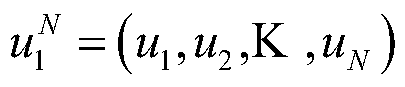 是一个二进制的行矢量,长度为N(即码长);G
N是一个N×N的矩阵,且
是一个二进制的行矢量,长度为N(即码长);G
N是一个N×N的矩阵,且
 定义为log
2N个矩阵F
2的克罗内克(Kronecker)乘积。上述矩阵
定义为log
2N个矩阵F
2的克罗内克(Kronecker)乘积。上述矩阵

Polar码的编码过程中,
 中的一部分比特用来携带信息,称为信息比特集合,这些比特的索引的集合记作
 另外的一部分比特设置为接收端和发送端预先约定的固定值,称之为固定比特集合或冻结比特集合(frozen bits),其索引的集合用
 的补集
的补集
 表示。Polar码的编码过程相当于:
 这里,GN.(A)是GN.中由集合
 中的索引对应的那些行得到的子矩阵,GN.(AC)是GN.中由集合
 中的索引 对应的那些行得到的子矩阵。
 为
为
 中的信息比特集合,数量为K;
 为
为
 中的固定比特集合,其数量为(N-K),是已知比特。这些固定比特通常被设置为0,但是只要接收端和发送端预先约定,固定比特可以被任意设置。从而,Polar码的编码输出可简化为:
 这里
这里
 为
为
 中的信息比特集合,
 为长度K的行矢量,即
 |·|表示集合中元素的个数,K为信息块大小,
 是矩阵G
N中由集合
是矩阵G
N中由集合
 中的索引对应的那些行得到的子矩阵,
 是一个K×N的矩阵。
Polar码的构造过程即集合
 的选取过程,决定了Polar码的性能。Polar码的构造过程通常是,根据母码码长N确定共存在N个极化信道,分别对应编码矩阵的N个行,计算极化信道可靠度,将可靠度较高的前K个极化信道的索引作为集合
 的元素,剩余(N-K)个极化信道对应的索引作为固定比特的索引集合
 的元素。集合
 决定了信息比特的位置,集合
 决定了固定比特的位置。
图2为常用的无线通信的基本流程示意图,如图2所示,在发送端,信源依次经过信源编码、信道编码、数字调制后发出。在接收端,依次经过数字解调、信道译码、信源解码输出信宿。信道编码可以采用Polar码,而在信道译码的时候,可以采用SC译码、SCL译码等。为了提高Polar码的性能,现在又提出了很多在Polar码的基础上进行改进的技术,例如,CA-Polar码,PC-Polar码,CA-PC-Polar等等。
如图3及图4所示,对Polar码级联循环冗余校验(Cyclic Redundancy Check)比特的编码方式,简称CA-Polar。在译码过程中,通过CRC校验(Cyclic Redundancy Check,循环冗余校验),在SCL译码输出的候选路径中选择CRC通过的路径作为译码输出,这种译码算法称为CA-SCL(CRC-Aided Successive Cancellation List)译码算法,CA-SCL译码算法能显著提高Polar码的性能。
CA-Polar码的构造过程包括确定信息比特位置的过程。假设信息块大小为Kinfo,CRC长度为Kcrc,编码的母码码长为N,则只需要从N个极化信道中选择Kinfo+Kcrc个可靠度最高的作为信息比特,其余的作为静态冻结比特(或称为冻结比特)。在CA-Polar码的构造过程中,先对信息块进行CRC编码,然后将CRC编码后的比特映射到信息比特,在静态冻结比特放置收发两端约定的固定值,最后进行Arikan Polar编码,得到CA-Polar的编码块。所述CRC比特可以级联在所述信息块的前端或后端,或者分布在所述信息块的内部。
译码时,信息块和CRC比特均未知,按照正常的SCL译码。在SCL译码结束后,得到L(路径扩展的宽度)个候选译码结果,所述候选译码结果包括信息块和CRC比特。从PM最小的路径的候选译码结果开始,对每个候选译码结果进行CRC校验,如果校验通过,则将该路径的信息块作为译码输出。否则,将PM最小的路径的候选译码结果的信息块作为译码输出,或者直接指示译码失败。CA-Polar可以取得比SCL更低的误块率(Block Error Rate,BLER)。
在SCL译码过程中,CRC比特均作为信息比特处理,只在SCL译码结束时用于选择路径。
如图5所示,对Polar码级联校验(Parity-check)比特,简称为PC-Polar,是另一种提升Polar码性能的级联码方法。PC-Polar的主要思想是选择一些校验比特(Parity-check-frozen),也称为动态冻结(Dynamic Frozen)比特或校验冻结比特,分布到信息块中,并且校验比特的值由其前面的信息比特根据校验方程确定。
PC-Polar主要是通过对信息块进行PC编码提升Polar码的最小码距,从而提升Polar码的性能。PC-Polar的构造主要包括两点,一是校验比特的位置,通常需要位于可靠度较高的极化信道;二是校验方程,即各校验比特由其前面的哪些信息比特确定。一旦构造完成,PC-Polar码的编码过程与CA-Polar类似,包括PC编码和Arikan编码两步,PC编码即根据校验方程和信息块的值确定校验比特的值,静态冻结比特仍然放置收发两端已知的值。PC-Polar的译码算法基于SCL译码算法,信息比特和静态冻结比特的处理与SCL译码算法的处理一样,不同是动态冻结比特的处理。由于动态冻结比特并不是未知的信息比特,而是由其前面的信息比特确定,其处理与静态冻结比特类似,不同的是动态冻结比特的值由前面译码的信息比特计算获得。动态冻结比特由于与前面的信息比特相关,实际上辅助了信息比特译码结果的校验。具体来说,如果前面译码的信息比特有错,计算得到动态冻结比特的值与其LLR(Log likelihood ratio对数似然比)不符的可能性更大,相应的路径PM会加惩罚值,从而在排序时会更可能把该错误路径删除。PC-SCL译码最终输出PM最小的路径。
图6是一个PC-Polar的SCL译码示例,动态冻结比特与信息比特之间的箭头表示的是动态冻结比特与信息比特之间的校验关系。在译码到动态冻结比特时,在各译码路径,根据校验关系将译码得到的信息比特的值计算得到该动态冻结比特的值,并用于译码。PC-Polar中动态冻结比特的位置对性能起到重要作用,构造时需要仔细挑选。
图7(a)为常用的CA-Polar和PC-Polar级联编码的流程示意图,如图7(a)所示,(1)对待编码的比特序列a
0,a
1,a
2,...,a
A-1先进行级联循环冗余校验(Cyclic Redundancy Check,CRC)编码得到b0,b1,……bB-1;(2)再进行PC编码,根据确定的信息比特、静态冻结比特(或称为冻结比特)和校验冻结比特的位置分别设置信息比特、静态冻结比特和校验冻结比特的值,生成序列c
0,c
1,...,c
C-1;(3)然后进行Polar编码(即极化编码)得到序列d
0,d
1,d
2...,d
D-1,最后进行速率匹配得到序列e
0,e
1,e
2...,e
E-1进行发送。CRC编码矩阵由如下参数唯一确定:CRC校验比特的数量、CRC校验比特的位置和CRC校验方程。而PC编码是由如下参数确定:校验冻结比特的位置和校验方程。
有一种级联CRC的Polar编码方法的实现步骤为:首先确定信息比特、静态冻结比特和校验比特的位置。然后将待编码的比特序列进行CRC编码,即进行CRC计算(其中,A表示信息比特的长度,B表示信息比特和CRC校验比特的长度之和),CRC计算的输入是信息比特a
0,a
1,a
2,...,a
A-1,生成的校验比特是p
0,p
1,p
2,...,p
Kcrc-1。采用如下方式进行CRC编码得到b0,b1,……bB-1,其中,
b
k=a
k for k=0,1,2,...,A-1;
b
k=p
k-A for k=A,A+1,A+2,...,B-1;
在CRC编码得到的CRC编码序列b0,b1,……bB-1中设置信息比特、静态冻结比特和校验冻结比特的值。具体可采用如下方式进行信息比特、静态冻结比特以及校验冻结比特的值的设置,得到序列c
0,c
1,...,c
C-1(C表示设置完信息比特、静态冻结比特以及校验冻结比特的值之后的序列长度,即C等于母码长度N),其中,
c
i=b
j for i∈信息比特;
c
i=0 for i∈冻结比特;
c
i=f(b
j) for i∈校验冻结比特,f(.)表示校验方程;
然后进行Arikan Polar编码,其中(D表示Arikan Polar编码后的序列长度,与N相等):
最后进行速率匹配。从d
0,d
1,d
2...,d
D-1序列中去除不传输的序列,得到传输序列e
0,e
1,e
2...,e
E-1,E表示速率匹配后的序列长度,即码长。完成编码后可将得到的传输序列发送给接收设备。
然而,该编码方法中CRC编码与PC编码(校验冻结比特值与校验方程的确定)是分别进行的。
图7(b)为常用的CA-Polar和PC-Polar级联编码的译码示意图,如图7(b)所示,首先SCL对Polar码进行译码,并输出L个幸存路径(L是一个参数),然后对这些幸存路径进行CRC校验,选择CRC通过的路径为译码输出。这里如果没有路径通过CRC校验,译码失败,可以选择最大概率路径作为输出;如果多于一个路径通过CRC校验,选择其中概率最大的路径作为输出。
上述介绍的各种概念或实施方式适用于下述的任意一个实施例中。
本申请提供的编码方法和译码方法的应用在网络设备与终端之间的信息交互过程中,编码侧既可以是网络设备也可以是终端;与之相应的,译码侧既可以是终端也可以是网络设备。可选的,也可以应用在终端之间的信息交互过程中,对此本申请不做限制。
在下述的各个编码方法的实施例中,辅助比特是指在编码端动态生成的,并且在解码端用于辅助译码的比特,所述的辅助译码是指进行纠错、进行检错或帮助判断是否提前终止译码等。所述辅助比特可以包括校验冻结比特(也可以称为冻结校验比特、PC—frozen比特、Parity-check-frozen比特、预冻结比特、校验比特、动态冻结(Dynamic Frozen)比特或PC校验比特),HASH(哈希)校验比特,分布式CRC比特以及CRC校验比特中的至少一种。
图8为本申请提供的编码方法的实施例的流程示意图,如图8所示,该编码方法具体包括:
S101:接收待编码的比特序列;
S102:将状态空间模块中的状态空间值进行初始化,并从所述待编码的比特序列中获取一组由Z个信息比特组成的Z个待编码比特;
S104:根据所述步骤S102中获取的所述Z个待编码比特中的值,以及所述状态空间模块中的状态空间值,从索引模块中获取对应的索引值,根据所述索引值和所述状态空间值进行运算,得到新的状态空间值,并将所述状态空间模块中的状态空间值更新为所述新的状态空间值;
S105:对所述步骤S102中获取的所述Z个待编码比特进行编码,在所述待编码的比特序列中有辅助比特位于所述Z个信息比特中的各个信息比特之间的情况下,以及,在所述待编码的比特序列中有辅助比特位于所述Z个信息比特与下一个信息比特之间的情况下,从所述新的状态空间值中获取数值赋给所述辅助比特;然后执行步骤S106;
S106:从所述待编码的比特序列中获取所述一组Z个待编码比特之后的下一组由Z个信息比特组成的Z个待编码比特,所述下一组Z个待编码比特与所述一组Z个待编码比特相邻,并将所述下一组Z个待编码比特作为所述步骤S104的输入,并执行所述步骤S104,及所述步骤S105,不断循环,直至所述下一组Z个待编码比特为所述待编码的比特序列中最后的待编码比特。
在图8所示的编码方法的实施例中,针对所述待编码的比特序列中的信息比特,每次处理Z个信息比特,直到将所述待编码的比特序列中的信息比特处理完毕。
在图8所示的编码方法的实施例中,通过在编码端进行辅助比特编码,使得解码端能够采用辅助比特对编码后的比特序列进行纠错、检错或者早停等辅助译码操作。并且由于每次针对Z个待编码比特进行编码,采用这种块处理的方式进行辅助比特编码,方便硬件实施,可以有效提升编码效率与吞吐量。
在图8所示的编码方法的实施例中,在所述步骤S106中:从所述待编码的比特序列中获取所述一组Z个待编码比特之后的下一组由Z个信息比特组成的Z个待编码比特,所述下一组由Z个信息比特组成的Z个待编码比特与所述一组由Z个信息比特组成的Z个待编码比特相邻是指:如图9所示,图9表示的一串待编码的比特序列,其中F表示冻结比特,I表示信息比特,PF表示辅助比特。在Z为2的情况下,从所述待编码的比特序列中连续的提取信息比特,在从所述待编码的比特序列中获取2个信息比特之后,接着再从所述待编码的比特序列中获取2个信息比特时,在所述待编码的比特序列中两次获取的信息比特之间不存在信息比特。
在图8所示的编码方法的实施例中,在所述步骤S102中,所述获取的Z个待编码比特中Z个信息比特之间的前后次序与所述Z个信息比特在所述待编码的比特序列中的前后次序是一致的。具体来讲,如图9所示,图9表示的是一串待编码的比特序列,其中F表示冻结比特,I表示信息比特,PF表示辅助比特。在Z为2的情况下,从所述待编码的比特序列中连续的提取信息比特。在所述步骤S105中:在所述待编码的比特序列中有辅助比特位于所述Z个信息比特中的各个信息比特之间的情况是指:如图9中所示,从所述待编码的比特序列中获取2个信息比特的过程中,跳过了这2个信息比特之间的1个辅助比特,则要从所述新的状态空间值中获取数值赋给这1个辅助比特。如果这2个信息比特之 间存在2个或多个辅助比特的情况下,则要从所述新的状态空间值中获取数值赋给这2个或多个辅助比特。在所述待编码的比特序列中有辅助比特位于所述Z个信息比特与下一个信息比特之间的情况是指:如图9所示,从所述待编码的比特序列中获取2个信息比特之后,接着再从所述待编码的比特序列中获取2个信息比特时,跳过了1个辅助比特,则要从所述新的状态空间值中获取数值赋给这1个辅助比特。如果两次获取的信息比特之间存在2个或多个辅助比特的情况下,则要从所述新的状态空间值中获取数值赋给这2个或多个辅助比特。
在图8所示的编码方法的实施例中,在所述待编码的比特序列中有辅助比特位于所述Z个信息比特中的各个信息比特之间的情况下,以及,在所述待编码的比特序列中有辅助比特位于所述Z个信息比特与下一个信息比特之间的情况下,从所述新的状态空间值中获取数值赋给所述辅助比特,包括:分别从所述新的状态空间值中获取数值赋给位于所述Z个信息比特中的各个信息比特之间的辅助比特,以及位于所述Z个信息比特与下一个信息比特之间的辅助比特。赋给所述Z个信息比特中的各个信息比特之间的辅助比特的数值,以及赋给位于所述Z个信息比特与下一个信息比特之间的辅助比特的数值,可以从所述新的状态空间值中的同一位置获取,或者是从所述新的状态空间值中的不同的位置获取。一般来讲,赋给这两种辅助比特的数值可以是相同的,或者是不同的。
在所述图8所示的编码方法的实施例中,在所述步骤S106中,所述下一组Z个待编码比特为所述待编码的比特序列中最后的待编码比特是指:
所述待编码的比特序列最后还剩下小于或等于Z个信息比特。
在所述待编码的比特序列最后还剩下的信息比特不够Z个的情况下,将不足的部分填充固定值0或1。
在所述图8所示的编码方法的实施例中,步骤S104可以在步骤S105之前执行。
在图8所示的所述编码方法的实施例中,在所述步骤S104之前还包括:
对所述待编码的比特序列中的所述Z个待编码比特的2z种排列组合进行预编码,将预编码后的结果存储在所述索引模块中。所述预编码中所采用的编码方式与所述步骤S105中所述的编码中所采用的编码方式是一致的,所述预编码是所述步骤S105中所述的编码的预处理过程。具体来讲,所述预编码后的结果可以是指预编码值,所述预编码值作为索引值存储在所述索引模块中。所述索引模块中的索引值可以以索引表格的形式存储。具体来讲,所述索引值可以以离线存储的方式存储在所述索引模块中。
其中,所述步骤S105中所述的编码的编码方式可以认为是该编码方法实施例的目标编码方法,也就是说,所述步骤S105中所述的编码的编码方式可以认为是该编码方法实施例打算采用的编码方法。
在图8所示的所述编码方法的实施例中,在所述步骤S105中,对所述步骤S102中获取的所述Z个待编码比特进行编码的步骤中,所述的编码是指:检验编码方式的编码或信息摘要编码方式的编码或线性运算方式的编码。其中,检验编码方式的编码可以是CRC 编码或PC编码。信息摘要编码方式的编码可以是HASH(哈希)编码等。线性运算方式的编码可以为采用编码矩阵的方式的编码。
在图8所示的所述编码方法的实施例中,在所述步骤S104中,根据所述步骤S102中获取的所述Z个待编码比特中的值,以及所述状态空间模块中的状态空间值,从索引模块中获取对应的索引值,包括:
将所述状态空间值的低Z个比特位与所述步骤S102中获取的的所述Z个待编码比特中的值进行运算,得到索引ID,并通过该索引ID获得索引模块中存储的索引值。
在图8所示的所述编码方法的实施例中,在所述步骤S104中,根据所述索引值和所述状态空间值进行运算的操作,包括:
将所述索引值和所述状态空间值进行按位逻辑运算。
具体的按位逻辑运算方式可以为按位异或运算,或者按位与运算、或者按位或运算、或者按位与非运算等。
将所述索引值和所述状态空间值进行按位逻辑运算具体可以是:将所述索引值与所述状态空间值的低Z位进行按位逻辑运算。
在图8所示的所述编码方法的实施例中,在采用CRC编码或PC编码的情况下,在所述步骤S104中,根据所述索引值和所述状态空间值进行运算的操作包括:将所述索引值和所述状态空间值进行按位异或(XOR)运算。
在图8所示的所述编码方法的实施例中,在所述步骤S104中,根据所述步骤S102中获取的所述Z个待编码比特中的值,以及所述状态空间模块中的状态空间值,从索引模块中获取对应的索引值,包括:
S1041:将所述状态空间值按照固定方向(例如:向左或向右)循环移Z个比特位,之后,将所述状态空间值的低Z个比特位与所述步骤S102中获取的所述Z个待编码比特中的值进行运算,得到索引ID,并通过该索引ID获得索引模块中存储的索引值。
相应地,在所述步骤S104中,根据所述索引值和所述状态空间值进行运算的操作,包括:
S1042:将所述索引值和所述状态空间值进行按位逻辑运算。例如:将所述索引值与状态空间值的低Z位进行按位逻辑运算。
在图8所示的所述编码方法的实施例中,所述状态空间模块具体可以为一个CRC寄存器组。根据编码中采用的CRC的类型,确定CRC寄存器组的存储空间,一般来讲,CRC寄存器组的储存空间可以为CRC长度的两倍,如果CRC的长度为Z比特,那么CRC寄存器组的存储空间可以为2Z比特,每次可以处理Z个待编码比特。
在所述步骤S104中,根据所述步骤S102中获取的所述Z个待编码比特中的值,以及所述状态空间模块中的状态空间值,从索引模块中获取对应的索引值,还可以包括:
S1043:将CRC寄存器组高Z比特位与根据所述步骤S102中获取的所述Z个待编码比特中的值进行异或运算,得到索引ID,并通过该索引ID获得索引模块中对应的索引值。
相应地,在所述步骤S104中,根据所述索引值和所述状态空间值进行运算的操作,包括:
S1044:将CRC寄存器组中全部的比特位按照固定方向(例如:向左或向右)循环移Z个比特位,之后,将所述索引值与CRC寄存器组低Z位做异或运算,得到新的状态空间值。
相应地,在所述步骤S105中,从所述新的状态空间值中获取数值赋给所述辅助比特的处理中,所述辅助比特是指PC校验比特。
图10为本申请提供的另一种编码方法的实施例的流程示意图,如图10所示,该编码方法具体包括:
S201:接收待编码的比特序列;
S202:将状态空间模块中的状态空间值进行初始化,并从所述待编码的比特序列中获取一组由信息比特和辅助比特组成的Z个待编码比特,然后执行步骤S203;
S203:将所述Z个待编码比特中的辅助比特的位置置为固定值,然后执行步骤S204;
S204:根据执行步骤S203后输出的所述Z个待编码比特中的值,以及所述状态空间模块中的状态空间值,从索引模块中获取对应的索引值,根据所述索引值和所述状态空间值进行运算,得到新的状态空间值,并将所述状态空间模块中的状态空间值更新为所述新的状态空间值;
S205:对执行步骤S203后输出的所述Z个待编码比特进行编码,并从所述新的状态空间值中获取数值赋给所述Z个待编码比特中的所述辅助比特;然后执行步骤S206;
S206:从所述待编码的比特序列中获取所述一组Z个待编码比特之后的下一组由信息比特和辅助比特组成的Z个待编码比特,所述下一组Z个待编码比特与所述一组Z个待编码比特相邻,并将所述下一组Z个待编码比特作为所述步骤S203的输入,并执行所述步骤S203,所述步骤S204,及所述步骤S205,不断循环,直至所述下一组Z个待编码比特为所述待编码的比特序列中最后的待编码比特。
在图10所示的编码方法的实施例中,针对所述待编码的比特序列中的信息比特和辅助比特,每次处理的Z个待编码比特中既包括信息比特也包括辅助比特,并且连续的提取所述所述待编码的比特序列中的信息比特和辅助比特,直到将所述待编码的比特序列中的信息比特和辅助比特处理完毕。
在图10所示的编码方法的实施例中,通过在编码端进行辅助比特编码,使得解码端能够采用辅助比特对编码后的比特序列进行纠错、检错或者早停等辅助译码操作。并且由于每次针对Z个待编码比特进行编码,采用这种块处理的方式进行辅助比特编码,方便硬件实施,可以有效提升编码效率与吞吐量。
在图10所示的所述编码方法的实施例中,在所述步骤S202中,所述获取的Z个待编码比特中信息比特和辅助比特之间的前后次序与所述信息比特和所述辅助比特在所述待编码的比特序列中的前后次序是一致的。具体来讲,如图9所示,在Z为4的情况下,从所述待编码的比特序列中连续的提取所述信息比特和所述辅助比特。
在图10所示的所述编码方法的实施例中,在所述步骤S206中,从所述待编码的比特序列中获取所述一组Z个待编码比特之后的下一组由信息比特和辅助比特组成的的Z个待编码比特,所述下一组Z个待编码比特与所述一组Z个待编码比特相邻,是指:如图9所 示,在Z为4的情况下,从所述待编码的比特序列中连续的提取信息比特和辅助比特,从所述待编码的比特序列中连续的获取信息比特和辅助比特之后,接着再从所述待编码的比特序列中获取信息比特和辅助比特时,在所述待编码的比特序列中,两次获取的4个待编码比特之间不存在信息比特,也不存在辅助比特。
在所述图10所示的编码方法的实施例中,在所述步骤S206中,所述下一组Z个待编码比特为所述待编码的比特序列中最后的待编码比特是指:
所述待编码的比特序列最后还剩下的比特中的信息比特和辅助比特的总数等于Z个或不足Z个。
在所述待编码的比特序列最后还剩下的比特中的信息比特和辅助比特的总数不足Z个的情况下,将不足的部分填充固定值0或1。
在所述图10所示的编码方法的实施例中,在所述步骤S203中,所述信息比特的位置的值不需要改变。
在所述图10所示的编码方法的实施例中,步骤S204可以在步骤S205之前执行。
在图10所示的所述编码方法的实施例中,在所述步骤204之前还包括:
对所述待编码的比特序列中的所述Z个待编码比特的2z种排列组合进行预编码,将预编码后的结果存储在所述索引模块中。所述预编码中所采用的编码方式与所述步骤S205中所述的编码中所采用的编码方式是一致的,所述预编码是所述步骤S205中所述的编码的预处理过程。具体来讲,所述预编码后的结果可以是指预编码值,所述预编码值作为索引值存储在所述索引模块中。所述索引模块中的索引值可以以索引表格的形式存储。具体来讲,所述索引值可以以离线存储的方式存储在所述索引模块中。
其中,所述的预编码是针对未经过步骤S203处理的Z个待编码比特进行处理的。所述步骤S205中所述的编码的编码方式可以认为是该编码方法实施例的目标编码方法,也就是说,所述步骤S205中所述的编码的编码方式可以认为是该编码方法实施例打算采用的编码方法。
在图10所示的所述编码方法的实施例中,在所述步骤S205中,对执行步骤S203后输出的所述Z个待编码比特进行编码的步骤中,所述的编码是指:检验编码方式的编码或信息摘要编码方式的编码或线性运算方式的编码。其中,检验编码方式的编码可以是CRC编码或PC编码。信息摘要编码方式的编码可以是HASH(哈希)编码等。线性运算方式的编码可以为采用编码矩阵的方式的编码。
在图10所示的所述编码方法的实施例中,在所述步骤S204中,根据执行步骤S203后输出的所述Z个待编码比特中的值,以及所述状态空间模块中的状态空间值,从索引模块中获取对应的索引值,包括:
将所述状态空间值的低Z个比特位与所述执行步骤S203后输出的所述Z个待编码比特中的值进行运算,得到索引ID,并通过该索引ID获得索引模块中存储的索引值。
在图10所示的所述编码方法的实施例中,在所述步骤S204中,根据所述索引值和所述状态空间值进行运算的操作,包括:
将所述索引值和所述状态空间值进行按位逻辑运算。
具体的按位逻辑运算方式可以为按位异或运算,或者按位与运算、或者按位或运算、或者按位与非运算等。
将所述索引值和所述状态空间值进行按位逻辑运算具体可以是:将所述索引值与所述状态空间值的低Z位进行按位逻辑运算。
在图10所示的所述编码方法的实施例中,在采用CRC编码或PC编码的情况下,在所述步骤S204中,根据所述索引值和所述状态空间值进行运算的操作包括:将所述索引值和所述状态空间值进行按位异或(XOR)运算。
在图10所示的所述编码方法的实施例中,在所述步骤S204中,根据执行步骤S203后输出的所述Z个待编码比特中的值,以及所述状态空间模块中的状态空间值,从索引模块中获取对应的索引值,包括:
S2041:将所述状态空间值按照固定方向(例如:向左或向右)循环移Z个比特位,之后,将所述状态空间值的低Z个比特位与所述执行步骤S203后输出的所述Z个待编码比特中的值进行运算,得到索引ID,并通过该索引ID获得索引模块中存储的索引值。
相应地,在所述步骤S204中,根据所述索引值和所述状态空间值进行运算的操作,包括:
S2042:将所述索引值和所述状态空间值进行按位逻辑运算。例如:将所述索引值与状态空间值的低Z位进行按位逻辑运算。
在图10所示的所述编码方法的实施例中,所述状态空间模块具体可以为一个CRC寄存器组。根据编码中采用的CRC的类型,确定CRC寄存器组的存储空间,一般来讲,CRC寄存器组的储存空间可以为CRC长度的两倍,如果CRC的长度为Z比特,那么CRC寄存器组的存储空间可以为2Z比特,每次可以处理Z个待编码比特。
在所述步骤S204中,根据执行步骤S203后输出的所述Z个待编码比特中的值,以及所述状态空间模块中的状态空间值,从索引模块中获取对应的索引值,还可以包括:
S2043:将CRC寄存器组高Z比特位与所述执行步骤S203后输出的所述Z个待编码比特中的值进行异或运算,得到索引ID,并通过该索引ID获得索引模块中对应的索引值。
相应地,在所述步骤S204中,根据所述索引值和所述状态空间值进行运算的操作,包括:
S2044:将CRC寄存器组中全部的比特位按照固定方向(例如:向左或向右)循环移动Z个比特位,之后,将所述索引值与CRC寄存器组低Z位做异或运算,得到新的状态空间值。
相应地,在所述步骤S205中,从所述新的状态空间值中获取数值赋给所述辅助比特的处理中,所述辅助比特是指PC校验比特。
图11为本申请提供的再一种编码方法的实施例的流程示意图,如图11所示,该编码方法具体包括:
S301:接收待编码的比特序列;
S302:将状态空间模块中的状态空间值进行初始化,并从所述待编码的比特序列中获取一组相邻的Z个待编码比特,然后执行步骤S303;
S303:所述Z个待编码比特包括信息比特,冻结比特,以及辅助比特中的至少一种,在所述Z个待编码比特包括有辅助比特的情况下,将所述辅助比特的位置置为固定值,在所述Z个待编码比特包括有冻结比特的情况下,将所述冻结比特的位置置为固定值,然后执行步骤S304;
S304:根据执行步骤S303后输出的所述Z个待编码比特中的值,以及所述状态空间模块中的状态空间值,从索引模块中获取对应的索引值,根据所述索引值和所述状态空间值进行运算,得到新的状态空间值,并将所述状态空间模块中的状态空间值更新为所述新的状态空间值;
S305:对执行步骤S303后输出的所述Z个待编码比特进行编码,在所述Z个待编码比特包括有所述辅助比特的情况下,从所述新的状态空间值中获取数值赋给所述辅助比特;然后执行步骤S306;
S306:从所述待编码的比特序列中获取所述一组Z个待编码比特之后的下一组相邻的Z个待编码比特,所述下一组Z个待编码比特与所述一组Z个待编码比特相邻,并将所述下一组Z个待编码比特作为所述步骤S303的输入,并执行所述步骤S303,所述步骤S304及所述步骤S305,不断循环,直至所述下一组Z个待编码比特为所述待编码的比特序列中最后的待编码比特。
在图11所示的编码方法的实施例中,针对所述待编码的比特序列中的信息比特,冻结比特以及辅助比特,每次从待编码的比特序列中连续的提取Z个比特进行处理,直到将所述待编码的比特序列中的比特处理完毕。所述Z个待编码比特可能包括所述信息比特,所述冻结比特,以及所述辅助比特中的一种或多种。
本申请的上述实施例中,通过在编码端进行辅助比特编码,使得解码端能够采用辅助比特对编码后的比特序列进行纠错、检错或者早停等辅助译码操作。并且由于每次针对Z个待编码比特进行编码,采用这种块处理的方式进行辅助比特编码,方便硬件实施,可以有效提升编码效率与吞吐量。
在图11所示的所述编码方法的实施例中,在所述步骤S302中,所述获取的Z个待编码比特中的信息比特,辅助比特和冻结比特之间的前后次序与所述信息比特,所述辅助比特和所述冻结比特在所述待编码的比特序列中的前后次序是一致的。具体来讲,如图9所示,在Z为4的情况下,从所述待编码的比特序列中连续的提取所述信息比特,所述辅助比特和所述冻结比特。
在所述图11所示的编码方法的实施例中,在所述步骤S306中,所述下一组相邻的Z个待编码比特为所述待编码的比特序列中最后的待编码比特是指:
所述待编码的比特序列最后还剩下小于或等于Z个待编码比特,在所述待编码的比特序列最后还剩下的待编码比特不够Z个的情况下,将不足的部分填充固定值0或1。
在所述图11所示的编码方法的实施例中,在所述步骤S303中,所述将所述冻结比特的位置置为固定值,其中,所述固定值是指编码端(或编码侧)和译码端(或译码侧)约定的固定值。
在所述图11所示的编码方法的实施例中,在所述步骤S303中,所述信息比特的位置的值不需要改变。
在所述图11所示的编码方法的实施例中,所述步骤S304可以在步骤S305之前执行。
在所述图10及图11所示的编码方法的实施例中,在所述步骤S203以及所述步骤S303中,将所述辅助比特的位置置为编码端(或编码侧)和译码端(或译码侧)约定的值即可,可以为0,也可以为1。
在上述的各个编码方法的实施例中,发送设备对待编码的比特序列进行编码得到编码后的比特序列,编码后的比特序列中包括信息比特,冻结比特,以及辅助比特,其中,所述辅助比特的值通过所述状态空间值获取。
在上述的各个编码方法的实施例中,Z为大于0的偶数。
在上述的各个编码方法的实施例中,所述状态空间模块的形式具体可以为寄存器,例如:寄存器组。
在上述的各个编码方法的实施例中,将状态空间模块中的状态空间值进行初始化的步骤中,所述状态空间模块中的值进行初始化后的值为:编码侧(或编码端)与译码侧(或译码端)之间约定的值。例如:初始化后的值可以为全“0”,或者编码侧与译码侧约定好的任意一种固定序列。具体的来讲,所述状态空间模块可以由寄存器组实现,在将寄存器组的状态初始化为全1时,在步骤S105,S205,以及S305中的从所述新的状态空间值中获取数值赋给所述辅助比特的操作中,应将新的状态空间值取反后,再将所述新的状态空间值中的至少一个位置的数值赋给所述辅助比特。
在所述图8,图10及图11所述的编码方法的实施例中,在执行所述步骤S105,S205,以及S305的过程中,从所述新的状态空间值中获取数值赋给所述辅助比特的步骤可以包括:将所述新的状态空间值中的至少一个位置的数值赋给所述辅助比特。
在所述图8,图10及图11所述的编码方法的实施例中,多次针对不同的Z个待编码比特执行所述步骤S105,S205,以及S305的过程中,多次从所述新的状态空间值中获取数值赋给所述辅助比特的步骤可以包括:每次从状态空间模块的固定位置获取数值赋给所述辅助比特;或者采用轮回旋转的方式,按某一个固定方向,从某一位置开始,在状态空间模块中逐次更替位置选取数值赋给所述辅助比特;或者采用某种伪随机方式,从状态空间模块中选取数值赋给所述辅助比特;或者采用某种函数(例如状态空间模块的存储空间大小与辅助比特的序号之间关系的函数),在计算出的所述状态空间模块中的位置上选取数值赋给所述辅助比特。
在图11所示的所述编码方法的实施例中,在所述步骤S304之前还包括:
对所述待编码的比特序列中的所述Z个待编码比特的2z种排列组合进行预编码,将预编码后的结果存储在所述索引模块中。所述预编码中所采用的编码方式与所述步骤S305中所述的编码中所采用的编码方式是一致的,所述预编码是所述步骤S305中所述的编码的预处理过程。具体来讲,所述预编码后的结果可以是指预编码值,所述预编码值作为索引值存储在所述索引模块中。所述索引模块中的索引值可以以索引表格的形式存储。具体来讲,所述索引值可以以离线存储的方式存储在所述索引模块中。
其中,所述的预编码是针对未经过步骤S303处理的Z个待编码比特进行处理的。所述步骤S305中所述的编码的编码方式可以认为是该编码方法实施例的目标编码方法,也就 是说,所述步骤S305中所述的编码的编码方式可以认为是该编码方法实施例打算采用的编码方法。
在图11所示的所述编码方法的实施例中,在所述步骤S305中,对执行步骤S303后输出的所述Z个待编码比特进行编码的步骤中,所述的编码是指:检验编码方式的编码或信息摘要编码方式的编码或线性运算方式的编码。其中,检验编码方式的编码可以是CRC编码或PC编码。信息摘要编码方式的编码可以是HASH(哈希)编码等。线性运算方式的编码可以为采用编码矩阵的方式的编码。
在图11所示的所述编码方法的实施例中,在所述步骤S304中,根据执行步骤S303后输出的所述Z个待编码比特中的值,以及所述状态空间模块中的状态空间值,从索引模块中获取对应的索引值,包括:
将所述状态空间值的低Z个比特位与所述执行步骤S303后输出的所述Z个待编码比特中的值进行运算,得到索引ID,并通过该索引ID获得索引模块中存储的索引值。
在图11所示的所述编码方法的实施例中,在所述步骤S304中,根据所述索引值和所述状态空间值进行运算的操作,包括:
将所述索引值和所述状态空间值进行按位逻辑运算。
具体的按位逻辑运算方式可以为按位异或运算,或者按位与运算、或者按位或运算、或者按位与非运算等。
将所述索引值和所述状态空间值进行按位逻辑运算具体可以是:将所述索引值与状态空间值的低Z位进行按位逻辑运算。
在图11所示的所述编码方法的实施例中,在采用CRC编码或PC编码的情况下,在所述步骤S304中,根据所述索引值和所述状态空间值进行运算的操作包括:将所述索引值和所述状态空间值进行按位异或(XOR)运算。
在图11所示的所述编码方法的实施例中,在所述步骤S304中,根据执行步骤S303后输出的所述Z个待编码比特中的值,以及所述状态空间模块中的状态空间值,从索引模块中获取对应的索引值,包括:
S3041:将所述状态空间值按照固定方向(例如:向左或向右)循环移Z个比特位,之后,将所述状态空间值的低Z个比特位与所述执行步骤S303后输出的所述Z个待编码比特中的值进行运算,得到索引ID,并通过该索引ID获得索引模块中存储的索引值。
相应地,在所述步骤S304中,根据所述索引值和所述状态空间值进行运算的操作,包括:
S3042:将所述索引值和所述状态空间值进行按位逻辑运算。例如:将所述索引值与状态空间值的低Z位进行按位逻辑运算。在图11所示的所述编码方法的实施例中,所述状态空间模块具体可以为一个CRC寄存器组。根据编码中采用的CRC的类型,确定CRC寄存器组的存储空间,一般来讲,CRC寄存器组的储存空间可以为CRC长度的两倍,如果CRC的长度为Z比特,那么CRC寄存器组的存储空间可以为2Z比特,每次可以处理Z个待编码比特。
在所述步骤S304中,根据执行步骤S303后输出的所述Z个待编码比特中的值,以及所述状态空间模块中的状态空间值,从索引模块中获取对应的索引值,还可以包括:
S3043:将CRC寄存器组高Z比特位与所述执行步骤S303后输出的所述Z个待编码比特中的值进行异或运算,得到索引ID,并通过该索引ID获得索引模块中对应的索引值。。
相应地,在所述步骤S304中,根据所述索引值和所述状态空间值进行运算的操作,包括:
S3044:将CRC寄存器组中全部的比特位按照固定方向(例如:向左或向右)循环移Z个比特位,之后,将所述索引值与CRC寄存器组低Z位做异或运算,得到新的状态空间值。
相应地,在所述步骤S305中,从所述新的状态空间值中获取数值赋给所述辅助比特的处理中,所述辅助比特是指PC校验比特。
在所述图8,图10及图11所述的编码方法的实施例中,在所述步骤S106或所述步骤S206或所述步骤S306之后还包括:
S3060:将所述待编码的比特序列中最后的待编码比特作为所述步骤S303的输入,并执行所述步骤S303,所述步骤S304及所述步骤S305之后,得到的所述状态空间模块中的状态空间值作为CRC校验比特,并进行CRC编码。
并且,在所述步骤S305或所述步骤S205或所述步骤S105中,从所述新的状态空间值中获取数值赋给所述辅助比特的处理中,所述辅助比特可以是指PC校验比特。结合步骤S3060,这样,本申请的上述实施例可以实现系统对不同种类辅助比特的同时编码,减少硬件开销,提升编码效率。
在所述图8,图10及图11所述的编码方法的实施例中,在所述步骤S106或所述步骤S206或所述步骤S306之后还包括:
S307:对编码后的比特序列进行极化编码和速率匹配得到待发送的速率匹配后的序列。
S308:发送速率匹配后的序列。
在所述图8,图10及图11所述的编码方法的实施例中,可以在执行所述S3060之后执行上述的步骤S307和步骤S308。
下面举一个具体的例子,在这个例子中的各种具体特征均可独立的并入上述的实施例。
在该例子中是利用一个17位比特的多项式生成所述状态空间值,并且所述所述状态空间值是位于16位(双字节)比特的状态空间模块中。在更新状态空间值的过程中,是以8个比特位(就是上述实施例中的Z为8的情况),也就是一个字节为单位来更新的。
状态空间值的更新过程包括:
将状态空间模块中的状态空间值初始化为全“0”,或者编码侧与译码侧约定好的任一种固定序列。
将状态空间模块中的状态空间值循环左移8位,并保存该状态空间值。
将状态空间模块中的状态空间值的低8位与8个待编码比特进行运算,得出一个指向索引表中相应的索引值。
将索引表中的索引值与状态空间模块中的状态空间值进行运算,得到新的状态空间值,并将所述状态空间模块中的状态空间值更新为所述新的状态空间值。
在上述的步骤2)中,采用寄存器是16位的寄存器,循环左移或循环右移8位的结果是一致的,都是实现寄存器高8为与低8位的交换。
下面再举一个具体的例子,在这个例子中的各种具体特征均可独立的并入上述的实施例。
在所述例子中,在进行CRC编码的同时,进行PC编码。并且在下面所述的例子中,Z为8,并且所述状态空间模块为一个CRC寄存器组。
该例子包括如下步骤:
将8个比特位的待编码比特所有可能的排列组合对应的CRC值制成索引表格,并将所述索引表格进行离线存储。
将CRC寄存器组的状态初始化为全"0"(0x0000)。(注意:CRC寄存器组初始化全为1时,最后得到的CRC比特应取反。)
将CRC寄存器组向左移8位,并保存到所述CRC寄存器组。
将左移8位之前的原CRC寄存器组高8位与所述8个比特位的待编码比特进行异或运算,得出一个指向表的索引。
索引所指的表值与CRC寄存器组做异或运算,得到新的状态空间值。
从所述新的状态空间值中获得PC比特的值,并针对下一个所述8个比特位的待编码比特执行前述的4),不断重复,直到处理完所述待编码的比特序列中最后的待编码比特。
所述待编码的比特序列中最后的待编码比特处理完之后,得出的状态空间值作为CRC比特,并进行CRC编码。
如图12所示,本发明实施例还提供了一种用于编码的处理装置504,该处理装置504可以通过硬件实现也可以通过软件实现,当通过硬件实现时,参见图12所示,该处理装置504包括:
输入接口电路5142,用于接收待编码的比特序列;
逻辑电路5144,用于将状态空间模块中的状态空间值进行初始化,并从所述待编码的比特序列中获取一组由Z个信息比特组成的Z个待编码比特;根据获取的所述Z个待编码比特,得到新的状态空间值,并为辅助比特赋值,所述根据获取的所述Z个待编码比特,得到新的状态空间值,并为辅助比特赋值包括:根据获取的所述Z个待编码比特中的值,以及所述状态空间模块中的状态空间值,从索引模块中获取对应的索引值,根据所述索引值和所述状态空间值进行运算,得到新的状态空间值,并将所述状态空间模块中的状态空间值更新为所述新的状态空间值;对所述获取的所述Z个待编码比特进行编码,在所述待编码的比特序列中有辅助比特位于所述Z个信息比特中的各个信息比特之间的情况下,以及,在所述待编码的比特序列中有辅助比特位于所述Z个信息比特与下一个信息比特之间的情况下,从所述新的状态空间值中获取数值赋给所述辅助比特;从所述待编码的比特序列中获取所述一组Z个待编码比特之后的下一组由Z个信息比特组成的Z个 待编码比特,所述下一组Z个待编码比特与所述一组Z个待编码比特相邻,并根据所述下一组Z个待编码比特,得到新的状态空间值,并为辅助比特赋值,不断循环,直至所述下一组Z个待编码比特为所述待编码的比特序列中最后的待编码比特。
在具体实现时,上述处理装置可以是芯片或者集成电路。
本发明实施例所提供的图12所示的所述处理装置可用于执行图8或图10或图11所示的所述编码方法的各种实施例,其实现原理和技术效果类似。具体来讲,本发明实施例所提供的图12所示的所述处理装置在用于执行图8所示的所述编码方法的各种实施例的情况下,图8所示的所述编码方法中关于步骤S101的各种具体实现方式,也相应地可以作为图12所示的所述处理装置的输入接口电路5142的功能的各种具体化的实现方式。图8所示的所述编码方法中关于步骤S102,S104,S105,S106,S3060,以及S307的各种具体实现方式,也相应地可以作为图12所示的所述处理装置的逻辑电路5144的功能的各种具体化的实现方式。
本发明实施例所提供的图12所示的所述处理装置在用于执行图10所示的所述编码方法的各种实施例的情况下,
所述输入接口电路5142,用于接收待编码的比特序列;
所述逻辑电路5144,用于将状态空间模块中的状态空间值进行初始化,并从所述待编码的比特序列中获取一组由信息比特和辅助比特组成的Z个待编码比特,根据获取的所述Z个待编码比特,得到新的状态空间值,并为辅助比特赋值,所述根据获取的所述Z个待编码比特,得到新的状态空间值,并为辅助比特赋值包括:将所述Z个待编码比特中的辅助比特的位置置为固定值,然后根据所述Z个待编码比特中的值,以及所述状态空间模块中的状态空间值,从索引模块中获取对应的索引值,根据所述索引值和所述状态空间值进行运算,得到新的状态空间值,并将所述状态空间模块中的状态空间值更新为所述新的状态空间值;针对将所述Z个待编码比特中的辅助比特的位置置为固定值之后的所述Z个待编码比特进行编码,并从所述新的状态空间值中获取数值赋给所述Z个待编码比特中的所述辅助比特;然后从所述待编码的比特序列中获取所述一组Z个待编码比特之后的下一组由信息比特和辅助比特组成的Z个待编码比特,所述下一组Z个待编码比特与所述一组Z个待编码比特相邻,并根据所述下一组Z个待编码比特,得到新的状态空间值,并为辅助比特赋值,不断循环,直至所述下一组Z个待编码比特为所述待编码的比特序列中最后的待编码比特。
具体来讲,图10所示的所述编码方法中关于步骤S201的各种具体实现方式,也相应地可以作为图12所示的所述处理装置的输入接口电路5142的功能的各种具体化的实现方式。图10所示的所述编码方法中关于步骤S202,S203,S204,S205,S206,S3060,以及S307的各种具体实现方式,也相应地可以作为图12所示的所述处理装置的逻辑电路的功能的各种具体化的实现方式。
本发明实施例所提供的图12所示的所述处理装置在用于执行图11所示的所述编码方法的各种实施例的情况下,
所述输入接口电路5142,用于接收待编码的比特序列;
所述逻辑电路5144,用于将状态空间模块中的状态空间值进行初始化,并从所述待编码的比特序列中获取一组相邻的Z个待编码比特,根据获取的所述Z个待编码比特,得到新的状态空间值,并为辅助比特赋值,所述根据获取的所述Z个待编码比特,得到新的状态空间值,并为辅助比特赋值包括:所述Z个待编码比特包括信息比特,冻结比特,以及辅助比特中的至少一种,在所述Z个待编码比特包括有辅助比特的情况下,将所述辅助比特的位置置为固定值,在所述Z个待编码比特包括有冻结比特的情况下,将所述冻结比特的位置置为固定值,然后根据所述Z个待编码比特中的值,以及所述状态空间模块中的状态空间值,从索引模块中获取对应的索引值,根据所述索引值和所述状态空间值进行运算,得到新的状态空间值,并将所述状态空间模块中的状态空间值更新为所述新的状态空间值;针对将所述Z个待编码比特中的辅助比特和冻结比特的位置置为固定值之后的所述Z个待编码比特进行编码,在所述Z个待编码比特包括有所述辅助比特的情况下,从所述新的状态空间值中获取数值赋给所述辅助比特;然后从所述待编码的比特序列中获取所述一组Z个待编码比特之后的下一组相邻的Z个待编码比特,所述下一组Z个待编码比特与所述一组Z个待编码比特相邻,并根据所述下一组Z个待编码比特,得到新的状态空间值,并为辅助比特赋值,不断循环,直至所述下一组Z个待编码比特为所述待编码的比特序列中最后的待编码比特。
具体来讲,图11所示的所述编码方法中关于步骤S301的各种具体实现方式,也相应地可以作为图12所示的所述处理装置的所述输入接口电路5142的功能的各种具体化的实现方式。图11所示的所述编码方法中关于步骤S302,S303,S304,S305,S306,S3060,以及S307的各种具体实现方式,也相应地可以作为图12所示的所述处理装置的逻辑电路的功能的各种具体化的实现方式。
当该处理装置504通过软件实现时,参见参见图13所示,该处理装置504包括:
存储器5044,用于存储程序;
处理器5042,用于执行所述存储器存储的所述程序,当所述程序被执行时,所述处理装置用于实现图8或图10或图11所示的所述编码方法的各种实施例。
上述存储器5044可以是物理上独立的单元,也可以与处理器5042集成在一起,具体参见图14所示。
参见图15所示,为本申请还提供一种通信设备500的实施例,用于实现编码的功能,该通信设备500包括:上述各个实施例中的处理装置504,以及收发器。
所述收发器,用于发送速率匹配后的序列。
上述通信设备可以是终端,也可以是网络设备。当该通信设备是终端时,参见图16所示,该终端600还可以包括电源512、用于给终端中的各种器件或电路提供电源;该终端还可以包括天线510,用于将收发器输出的上行数据通过无线信号发送出去,或者将收到的无线信号输出给收发器。
除此之外,为了使得终端的功能更加完善,该终端还可以包括输入单元514,显示单元516,音频电路518,摄像头520和传感器522等中的一个或多个,所述音频电路518可以包括扬声器5182,麦克风5184等。
结合前面的描述,本领域的技术人员可以意识到,本文实施例的方法,可以通过硬件(例如,逻辑电路),或者软件,或者硬件与软件的结合来实现。这些方法究竟以硬件还是软件方式来执行,取决于技术方案的特定应用和设计约束条件。专业技术人员可以对每个特定的应用来使用不同方法来实现所描述的功能,但是这种实现不应认为超出本申请的范围。
当上述功能通过软件的形式实现并作为独立的产品销售或使用时,可以存储在一个计算机可读取存储介质中。在这种情况下,本申请的技术方案本质上或者说对现有技术做出贡献的部分或者该技术方案的部分可以以软件产品的形式体现出来,该计算机软件产品存储在一个存储介质中,包括若干指令用以使得一台计算机设备(可以是个人计算机,服务器,或者网络设备等)执行本申请各个实施例所述方法的全部或部分步骤。而前述的存储介质包括:U盘、移动硬盘、只读存储器(ROM,Read-Only Memory)、随机存取存储器(RAM,Random Access Memory)、磁碟或者光盘等各种可以存储程序代码的介质。
以上所述,仅为本申请的具体实施方式,但本申请的保护范围并不局限于此,任何熟悉本技术领域的技术人员在本申请揭露的技术范围内,可轻易想到变化或替换,都应涵盖在本申请的保护范围之内。因此,本申请的保护范围应以所述权利要求的保护范围为准。
Claims (24)
- 一种编码方法,其特征在于,所述方法包括:S101:接收待编码的比特序列;S102:将状态空间模块中的状态空间值进行初始化,并从所述待编码的比特序列中获取一组由Z个信息比特组成的Z个待编码比特;S104:根据所述步骤S102中获取的所述Z个待编码比特中的值,以及所述状态空间模块中的状态空间值,从索引模块中获取对应的索引值,根据所述索引值和所述状态空间值进行运算,得到新的状态空间值,并将所述状态空间模块中的状态空间值更新为所述新的状态空间值;S105:对所述步骤S102中获取的所述Z个待编码比特进行编码,在所述待编码的比特序列中有辅助比特位于所述Z个信息比特中的各个信息比特之间的情况下,以及,在所述待编码的比特序列中有辅助比特位于所述Z个信息比特与下一个信息比特之间的情况下,从所述新的状态空间值中获取数值赋给所述辅助比特;然后执行步骤S106;S106:从所述待编码的比特序列中获取所述一组Z个待编码比特之后的下一组由Z个信息比特组成的Z个待编码比特,所述下一组Z个待编码比特与所述一组Z个待编码比特相邻,并将所述下一组Z个待编码比特作为所述步骤S104的输入,并执行所述步骤S104,及所述步骤S105,不断循环,直至所述下一组Z个待编码比特为所述待编码的比特序列中最后的待编码比特。
- 如权利要求1所述的编码方法,其特征在于,在所述步骤S104中,根据所述索引值和所述状态空间值进行运算的操作,包括:将所述索引值和所述状态空间值进行按位逻辑运算。
- 如权利要求1所述的编码方法,其特征在于,在所述步骤S104中,根据所述步骤S102中获取的所述Z个待编码比特中的值,以及所述状态空间模块中的状态空间值,从索引模块中获取对应的索引值,包括:S1041:将所述状态空间值按照固定方向循环移Z个比特位,之后,将所述状态空间值的低Z个比特位与所述步骤S102中获取的所述Z个待编码比特中的值进行运算,得到索引ID,并通过该索引ID获得索引模块中存储的索引值;相应地,在所述步骤S104中,根据所述索引值和所述状态空间值进行运算的操作,包括:S1042:将所述索引值和所述状态空间值进行按位逻辑运算。
- 如权利要求1所述的编码方法,其特征在于,在所述步骤S106之后还包括:S3060:将所述待编码的比特序列中最后的待编码比特作为所述步骤S104的输入,并执行所述步骤S104,及所述步骤S105之后,得到的所述状态空间模块中的状态空间值作为CRC校验比特,并进行CRC编码。并且,在所述步骤S105中,从所述新的状态空间值中获取数值赋给所述辅助比特的处理中,所述辅助比特是指PC校验比特。
- 一种编码方法,其特征在于,所述方法包括:S201:接收待编码的比特序列;S202:将状态空间模块中的状态空间值进行初始化,并从所述待编码的比特序列中 获取一组由信息比特和辅助比特组成的Z个待编码比特,然后执行步骤S203;S203:将所述Z个待编码比特中的辅助比特的位置置为固定值,然后执行步骤S204;S204:根据执行步骤S203后输出的所述Z个待编码比特中的值,以及所述状态空间模块中的状态空间值,从索引模块中获取对应的索引值,根据所述索引值和所述状态空间值进行运算,得到新的状态空间值,并将所述状态空间模块中的状态空间值更新为所述新的状态空间值;S205:对执行步骤S203后输出的所述Z个待编码比特进行编码,并从所述新的状态空间值中获取数值赋给所述Z个待编码比特中的所述辅助比特;然后执行步骤S206;S206:从所述待编码的比特序列中获取所述一组Z个待编码比特之后的下一组由信息比特和辅助比特组成的Z个待编码比特,所述下一组Z个待编码比特与所述一组Z个待编码比特相邻,并将所述下一组Z个待编码比特作为所述步骤S203的输入,并执行所述步骤S203,所述步骤S204,及所述步骤S205,不断循环,直至所述下一组Z个待编码比特为所述待编码的比特序列中最后的待编码比特。
- 如权利要求5所述的编码方法,其特征在于,在所述步骤S204中,根据所述索引值和所述状态空间值进行运算的操作,包括:将所述索引值和所述状态空间值进行按位逻辑运算。
- 如权利要求5所述的编码方法,其特征在于,在所述步骤S204中,根据执行步骤S203后输出的所述Z个待编码比特中的值,以及所述状态空间模块中的状态空间值,从索引模块中获取对应的索引值,包括:S2041:将所述状态空间值按照固定方向循环移Z个比特位,之后,将所述状态空间值的低Z个比特位与所述执行步骤S203后输出的所述Z个待编码比特中的值进行运算,得到索引ID,并通过该索引ID获得索引模块中存储的索引值;相应地,在所述步骤S204中,根据所述索引值和所述状态空间值进行运算的操作,包括:S2042:将所述索引值和所述状态空间值进行按位逻辑运算。
- 如权利要求5所述的编码方法,其特征在于,在所述步骤S206之后还包括:S3060:将所述待编码的比特序列中最后的待编码比特作为所述步骤S203的输入,并执行所述步骤S203,所述步骤S204及所述步骤S205之后,得到的所述状态空间模块中的状态空间值作为CRC校验比特,并进行CRC编码;并且,在所述步骤S205中,从所述新的状态空间值中获取数值赋给所述辅助比特的处理中,所述辅助比特是指PC校验比特。
- 一种编码方法,其特征在于,所述方法包括:S301:接收待编码的比特序列;S302:将状态空间模块中的状态空间值进行初始化,并从所述待编码的比特序列中获取一组相邻的Z个待编码比特,然后执行步骤S303;S303:所述Z个待编码比特包括信息比特,冻结比特,以及辅助比特中的至少一种,在所述Z个待编码比特包括有辅助比特的情况下,将所述辅助比特的位置置为固定值,在所述Z个待编码比特包括有冻结比特的情况下,将所述冻结比特的位置置为固定值,然后执行步骤S304;S304:根据执行步骤S303后输出的所述Z个待编码比特中的值,以及所述状态空间模块中的状态空间值,从索引模块中获取对应的索引值,根据所述索引值和所述状态空间值进行运算,得到新的状态空间值,并将所述状态空间模块中的状态空间值更新为所述新的状态空间值;S305:对执行步骤S303后输出的所述Z个待编码比特进行编码,在所述Z个待编码比特包括有所述辅助比特的情况下,从所述新的状态空间值中获取数值赋给所述辅助比特;然后执行步骤S306;S306:从所述待编码的比特序列中获取所述一组Z个待编码比特之后的下一组相邻的Z个待编码比特,所述下一组Z个待编码比特与所述一组Z个待编码比特相邻,并将所述下一组Z个待编码比特作为所述步骤S303的输入,并执行所述步骤S303,所述步骤S304及所述步骤S305,不断循环,直至所述下一组Z个待编码比特为所述待编码的比特序列中最后的待编码比特。
- 如权利要求9所述的编码方法,其特征在于,在所述步骤S304中,根据所述索引值和所述状态空间值进行运算的操作,包括:将所述索引值和所述状态空间值进行按位逻辑运算。
- 如权利要求9所述的编码方法,其特征在于,在所述步骤S304中,根据执行步骤S303后输出的所述Z个待编码比特中的值,以及所述状态空间模块中的状态空间值,从索引模块中获取对应的索引值,包括:S3041:将所述状态空间值按照固定方向循环移Z个比特位,之后,将所述状态空间值的低Z个比特位与所述执行步骤S303后输出的所述Z个待编码比特中的值进行运算,得到索引ID,并通过该索引ID获得索引模块中存储的索引值;相应地,在所述步骤S304中,根据所述索引值和所述状态空间值进行运算的操作,包括:S3042:将所述索引值和所述状态空间值进行按位逻辑运算。
- 如权利要求9所述的编码方法,其特征在于,在所述步骤S306之后还包括:S3060:将所述待编码的比特序列中最后的待编码比特作为所述步骤S303的输入,并执行所述步骤S303,所述步骤S304及所述步骤S305之后,得到的所述状态空间模块中的状态空间值作为CRC校验比特,并进行CRC编码;并且,在所述步骤S305中,从所述新的状态空间值中获取数值赋给所述辅助比特的处理中,所述辅助比特是指PC校验比特。
- 一种用于编码的处理装置,其特征在于,该处理装置包括:输入接口电路,用于接收待编码的比特序列;逻辑电路,用于将状态空间模块中的状态空间值进行初始化,并从所述待编码的比特序列中获取一组由Z个信息比特组成的Z个待编码比特;根据获取的所述Z个待编码比特,得到新的状态空间值,并为辅助比特赋值,所述根据获取的所述Z个待编码比特,得到新的状态空间值,并为辅助比特赋值包括:根据获取的所述Z个待编码比特中的值,以及所述状态空间模块中的状态空间值,从索引模块中获取对应的索引值,根据所述索引值和所述状态空间值进行运算,得到新的状态空间值,并将所述状态空间模块中的状态空间值更新为所述新的状态空间值;对所述获取的所述Z个待编码比特进行编码,在所 述待编码的比特序列中有辅助比特位于所述Z个信息比特中的各个信息比特之间的情况下,以及,在所述待编码的比特序列中有辅助比特位于所述Z个信息比特与下一个信息比特之间的情况下,从所述新的状态空间值中获取数值赋给所述辅助比特;从所述待编码的比特序列中获取所述一组Z个待编码比特之后的下一组由Z个信息比特组成的Z个待编码比特,所述下一组Z个待编码比特与所述一组Z个待编码比特相邻,并根据所述下一组Z个待编码比特,得到新的状态空间值,并为辅助比特赋值,不断循环,直至所述下一组Z个待编码比特为所述待编码的比特序列中最后的待编码比特。
- 如权利要求13所述的处理装置,其特征在于,所述根据所述索引值和所述状态空间值进行运算,包括:将所述索引值和所述状态空间值进行按位逻辑运算。
- 如权利要求13所述的处理装置,其特征在于,根据所述获取的所述Z个待编码比特中的值,以及所述状态空间模块中的状态空间值,从索引模块中获取对应的索引值,包括:将所述状态空间值按照固定方向循环移Z个比特位,之后,将所述状态空间值的低Z个比特位与所述获取的所述Z个待编码比特中的值进行运算,得到索引ID,并通过该索引ID获得索引模块中存储的索引值;相应地,根据所述索引值和所述状态空间值进行运算,包括:将所述索引值和所述状态空间值进行按位逻辑运算。
- 如权利要求13所述的处理装置,其特征在于,所述逻辑电路进一步用于:根据所述待编码的比特序列中最后的待编码比特得到新的状态空间值,并为辅助比特赋值,之后,得到的所述状态空间模块中的状态空间值作为CRC校验比特,并进行CRC编码。并且,在从所述新的状态空间值中获取数值赋给所述辅助比特时,所述辅助比特是指PC校验比特。
- 一种用于编码的处理装置,其特征在于,该处理装置包括:所述输入接口电路,用于接收待编码的比特序列;所述逻辑电路,用于将状态空间模块中的状态空间值进行初始化,并从所述待编码的比特序列中获取一组由信息比特和辅助比特组成的Z个待编码比特,根据获取的所述Z个待编码比特,得到新的状态空间值,并为辅助比特赋值,所述根据获取的所述Z个待编码比特,得到新的状态空间值,并为辅助比特赋值包括:将所述Z个待编码比特中的辅助比特的位置置为固定值,然后根据所述Z个待编码比特中的值,以及所述状态空间模块中的状态空间值,从索引模块中获取对应的索引值,根据所述索引值和所述状态空间值进行运算,得到新的状态空间值,并将所述状态空间模块中的状态空间值更新为所述新的状态空间值;针对将所述Z个待编码比特中的辅助比特的位置置为固定值之后的所述Z个待编码比特进行编码,并从所述新的状态空间值中获取数值赋给所述Z个待编码比特中的所述辅助比特;然后从所述待编码的比特序列中获取所述一组Z个待编码比特之后的下一组由信息比特和辅助比特组成的Z个待编码比特,所述下一组Z个待编码比特与所述一组Z个待编码比特相邻,并根据所述下一组Z个待编码比特,得到新的状态空间值,并为辅助比特赋值,不断循环,直至所述下一组Z个待编码比特为所述待编码的比特序列中最后的待编码比特。
- 如权利要求17所述的处理装置,其特征在于,根据所述索引值和所述状态空间值进行运算的操作,包括:将所述索引值和所述状态空间值进行按位逻辑运算。
- 如权利要求17所述的处理装置,其特征在于,根据所述Z个待编码比特中的值,以及所述状态空间模块中的状态空间值,从索引模块中获取对应的索引值,包括:将所述状态空间值按照固定方向循环移Z个比特位,之后,将所述状态空间值的低Z个比特位与所述Z个待编码比特中的值进行运算,得到索引ID,并通过该索引ID获得索引模块中存储的索引值;相应地,根据所述索引值和所述状态空间值进行运算,包括:将所述索引值和所述状态空间值进行按位逻辑运算。
- 如权利要求17所述的处理装置,其特征在于,所述逻辑电路进一步用于:根据所述待编码的比特序列中最后的待编码比特得到新的状态空间值,并为辅助比特赋值,之后,得到的所述状态空间模块中的状态空间值作为CRC校验比特,并进行CRC编码;并且,在从所述新的状态空间值中获取数值赋给所述辅助比特时,所述辅助比特是指PC校验比特。
- 一种用于编码的处理装置,其特征在于,该处理装置包括:所述输入接口电路,用于接收待编码的比特序列;所述逻辑电路,用于将状态空间模块中的状态空间值进行初始化,并从所述待编码的比特序列中获取一组相邻的Z个待编码比特,根据获取的所述Z个待编码比特,得到新的状态空间值,并为辅助比特赋值,所述根据获取的所述Z个待编码比特,得到新的状态空间值,并为辅助比特赋值包括:所述Z个待编码比特包括信息比特,冻结比特,以及辅助比特中的至少一种,在所述Z个待编码比特包括有辅助比特的情况下,将所述辅助比特的位置置为固定值,在所述Z个待编码比特包括有冻结比特的情况下,将所述冻结比特的位置置为固定值,然后根据所述Z个待编码比特中的值,以及所述状态空间模块中的状态空间值,从索引模块中获取对应的索引值,根据所述索引值和所述状态空间值进行运算,得到新的状态空间值,并将所述状态空间模块中的状态空间值更新为所述新的状态空间值;针对将所述Z个待编码比特中的辅助比特和冻结比特的位置置为固定值之后的所述Z个待编码比特进行编码,在所述Z个待编码比特包括有所述辅助比特的情况下,从所述新的状态空间值中获取数值赋给所述辅助比特;然后从所述待编码的比特序列中获取所述一组Z个待编码比特之后的下一组相邻的Z个待编码比特,所述下一组Z个待编码比特与所述一组Z个待编码比特相邻,并根据所述下一组Z个待编码比特,得到新的状态空间值,并为辅助比特赋值,不断循环,直至所述下一组Z个待编码比特为所述待编码的比特序列中最后的待编码比特。
- 如权利要求21所述的处理装置,其特征在于,根据所述索引值和所述状态空间值进行运算,包括:将所述索引值和所述状态空间值进行按位逻辑运算。
- 如权利要求21所述的处理装置,其特征在于,根据所述Z个待编码比特中的值,以及所述状态空间模块中的状态空间值,从索引模块中获取对应的索引值,包括:将所述状态空间值按照固定方向循环移Z个比特位,之后,将所述状态空间值的低Z个比特位与所述Z个待编码比特中的值进行运算,得到索引ID,并通过该索引ID获得 索引模块中存储的索引值;相应地,根据所述索引值和所述状态空间值进行运算,包括:将所述索引值和所述状态空间值进行按位逻辑运算。
- 如权利要求21所述的处理装置,其特征在于,所述逻辑电路进一步用于:根据所述待编码的比特序列中最后的待编码比特得到新的状态空间值,并为辅助比特赋值,之后,得到的所述状态空间模块中的状态空间值作为CRC校验比特,并进行CRC编码;并且,在从所述新的状态空间值中获取数值赋给所述辅助比特时,所述辅助比特是指PC校验比特。
Priority Applications (2)
| Application Number | Priority Date | Filing Date | Title |
|---|---|---|---|
| EP18794539.9A EP3614592A4 (en) | 2017-05-02 | 2018-05-02 | CODING METHOD AND DEVICE |
| US16/672,309 US11075715B2 (en) | 2017-05-02 | 2019-11-01 | Encoding method and apparatus |
Applications Claiming Priority (2)
| Application Number | Priority Date | Filing Date | Title |
|---|---|---|---|
| CN201710301564.2A CN108809485B (zh) | 2017-05-02 | 2017-05-02 | 一种编码的方法和装置 |
| CN201710301564.2 | 2017-05-02 |
Related Child Applications (1)
| Application Number | Title | Priority Date | Filing Date |
|---|---|---|---|
| US16/672,309 Continuation US11075715B2 (en) | 2017-05-02 | 2019-11-01 | Encoding method and apparatus |
Publications (1)
| Publication Number | Publication Date |
|---|---|
| WO2018202054A1 true WO2018202054A1 (zh) | 2018-11-08 |
Family
ID=64016465
Family Applications (1)
| Application Number | Title | Priority Date | Filing Date |
|---|---|---|---|
| PCT/CN2018/085368 WO2018202054A1 (zh) | 2017-05-02 | 2018-05-02 | 一种编码的方法和装置 |
Country Status (4)
| Country | Link |
|---|---|
| US (1) | US11075715B2 (zh) |
| EP (1) | EP3614592A4 (zh) |
| CN (1) | CN108809485B (zh) |
| WO (1) | WO2018202054A1 (zh) |
Families Citing this family (2)
| Publication number | Priority date | Publication date | Assignee | Title |
|---|---|---|---|---|
| CN108574560B (zh) | 2017-03-13 | 2020-07-24 | 华为技术有限公司 | 一种编码方法、译码方法、装置和设备 |
| CN111193519B (zh) * | 2020-01-09 | 2023-06-09 | 广西大学 | 一种基于辅助译码比特的Polar码编译码方法 |
Citations (4)
| Publication number | Priority date | Publication date | Assignee | Title |
|---|---|---|---|---|
| CN102122966A (zh) * | 2011-04-15 | 2011-07-13 | 北京邮电大学 | 基于信道极化的交错结构重复码的编码器及其编译码方法 |
| US8381083B2 (en) * | 2009-10-22 | 2013-02-19 | Arm Limited | Error control coding for single error correction and double error detection |
| CN104079370A (zh) * | 2013-03-27 | 2014-10-01 | 华为技术有限公司 | 信道编译码方法及装置 |
| CN105811998A (zh) * | 2016-03-04 | 2016-07-27 | 深圳大学 | 一种基于密度演进的极化码构造方法及极化码编译码系统 |
Family Cites Families (5)
| Publication number | Priority date | Publication date | Assignee | Title |
|---|---|---|---|---|
| US6571361B1 (en) * | 1995-09-29 | 2003-05-27 | Kabushiki Kaisha Toshiba | Encoder and decoder |
| CN108712231B (zh) * | 2012-10-17 | 2019-04-19 | 华为技术有限公司 | 一种编译码的方法、装置及系统 |
| CN103873197B (zh) * | 2014-03-11 | 2017-06-16 | 重庆邮电大学 | 空间相关性与分簇相结合的3d mimo有限反馈开销降低方法 |
| WO2016119105A1 (zh) | 2015-01-26 | 2016-08-04 | 华为技术有限公司 | 极化Polar码的生成方法和设备 |
| WO2016173922A1 (en) | 2015-04-30 | 2016-11-03 | Telefonaktiebolaget Lm Ericsson (Publ) | Decoding of messages |
-
2017
- 2017-05-02 CN CN201710301564.2A patent/CN108809485B/zh active Active
-
2018
- 2018-05-02 WO PCT/CN2018/085368 patent/WO2018202054A1/zh unknown
- 2018-05-02 EP EP18794539.9A patent/EP3614592A4/en active Pending
-
2019
- 2019-11-01 US US16/672,309 patent/US11075715B2/en active Active
Patent Citations (4)
| Publication number | Priority date | Publication date | Assignee | Title |
|---|---|---|---|---|
| US8381083B2 (en) * | 2009-10-22 | 2013-02-19 | Arm Limited | Error control coding for single error correction and double error detection |
| CN102122966A (zh) * | 2011-04-15 | 2011-07-13 | 北京邮电大学 | 基于信道极化的交错结构重复码的编码器及其编译码方法 |
| CN104079370A (zh) * | 2013-03-27 | 2014-10-01 | 华为技术有限公司 | 信道编译码方法及装置 |
| CN105811998A (zh) * | 2016-03-04 | 2016-07-27 | 深圳大学 | 一种基于密度演进的极化码构造方法及极化码编译码系统 |
Non-Patent Citations (1)
| Title |
|---|
| See also references of EP3614592A4 |
Also Published As
| Publication number | Publication date |
|---|---|
| EP3614592A4 (en) | 2020-04-29 |
| US20200067638A1 (en) | 2020-02-27 |
| CN108809485A (zh) | 2018-11-13 |
| CN108809485B (zh) | 2020-02-21 |
| EP3614592A1 (en) | 2020-02-26 |
| US11075715B2 (en) | 2021-07-27 |
Similar Documents
| Publication | Publication Date | Title |
|---|---|---|
| JP6584036B2 (ja) | 署名対応Polarエンコーダ及びデコーダ | |
| KR20190052054A (ko) | 극성 코드를 이용하여 데이터를 인코딩하기 위한 방법 및 장치 | |
| CN107659381B (zh) | 编译码方法及装置 | |
| WO2017193716A1 (zh) | 一种极化码的编码和速率匹配方法、装置及设备 | |
| US11171741B2 (en) | Polar code transmission method and apparatus | |
| WO2018137635A1 (zh) | Polar码编译码方法及装置 | |
| WO2019201269A1 (zh) | 极化码的编译码方法和装置 | |
| US11184028B2 (en) | Coding method, decoding method, apparatus, and device | |
| WO2017121334A1 (zh) | 一种数据处理的方法和装置 | |
| KR102289928B1 (ko) | 데이터 프로세싱 방법 및 디바이스 | |
| WO2018202166A1 (zh) | 一种Polar码传输方法及装置 | |
| TWI392267B (zh) | 提供線性消除碼之方法與裝置 | |
| WO2019001436A1 (zh) | 一种Polar码的编码方法及装置 | |
| US20230208554A1 (en) | Encoding and Decoding Method and Apparatus | |
| WO2018202054A1 (zh) | 一种编码的方法和装置 | |
| CN111446969A (zh) | 一种级联crc码的极化码编码方法及装置 | |
| WO2012109872A1 (zh) | 通信系统中的循环冗余校验处理方法、装置和lte终端 | |
| CN116491083A (zh) | 具有共享数据和协作解码的并行极化码 | |
| CN109088698B (zh) | 一种编码方法及通信设备 | |
| Dolev et al. | Multiplication free holographic coding | |
| CN109474383B (zh) | 编码方法及装置 | |
| CN109474376B (zh) | 编码方法及装置 | |
| CN109495208B (zh) | 编码方法及装置 | |
| CN109474378B (zh) | 编码方法及装置 | |
| CN109474380B (zh) | 编码方法及装置 |
Legal Events
| Date | Code | Title | Description |
|---|---|---|---|
| 121 | Ep: the epo has been informed by wipo that ep was designated in this application |
Ref document number: 18794539 Country of ref document: EP Kind code of ref document: A1 |
|
| NENP | Non-entry into the national phase |
Ref country code: DE |
|
| ENP | Entry into the national phase |
Ref document number: 2018794539 Country of ref document: EP Effective date: 20191118 |