WO2018201211A1 - Dispositif de retenue de câbles - Google Patents
Dispositif de retenue de câbles Download PDFInfo
- Publication number
- WO2018201211A1 WO2018201211A1 PCT/BR2018/050136 BR2018050136W WO2018201211A1 WO 2018201211 A1 WO2018201211 A1 WO 2018201211A1 BR 2018050136 W BR2018050136 W BR 2018050136W WO 2018201211 A1 WO2018201211 A1 WO 2018201211A1
- Authority
- WO
- WIPO (PCT)
- Prior art keywords
- housing
- cable
- drop
- shoulder
- retaining
- Prior art date
Links
Images


Classifications
-
- G—PHYSICS
- G02—OPTICS
- G02B—OPTICAL ELEMENTS, SYSTEMS OR APPARATUS
- G02B6/00—Light guides; Structural details of arrangements comprising light guides and other optical elements, e.g. couplings
- G02B6/44—Mechanical structures for providing tensile strength and external protection for fibres, e.g. optical transmission cables
- G02B6/4439—Auxiliary devices
- G02B6/4471—Terminating devices ; Cable clamps
-
- G—PHYSICS
- G02—OPTICS
- G02B—OPTICAL ELEMENTS, SYSTEMS OR APPARATUS
- G02B6/00—Light guides; Structural details of arrangements comprising light guides and other optical elements, e.g. couplings
- G02B6/46—Processes or apparatus adapted for installing or repairing optical fibres or optical cables
- G02B6/48—Overhead installation
-
- G—PHYSICS
- G02—OPTICS
- G02B—OPTICAL ELEMENTS, SYSTEMS OR APPARATUS
- G02B6/00—Light guides; Structural details of arrangements comprising light guides and other optical elements, e.g. couplings
- G02B6/44—Mechanical structures for providing tensile strength and external protection for fibres, e.g. optical transmission cables
-
- G—PHYSICS
- G02—OPTICS
- G02B—OPTICAL ELEMENTS, SYSTEMS OR APPARATUS
- G02B6/00—Light guides; Structural details of arrangements comprising light guides and other optical elements, e.g. couplings
- G02B6/46—Processes or apparatus adapted for installing or repairing optical fibres or optical cables
- G02B6/48—Overhead installation
- G02B6/483—Installation of aerial type
-
- H—ELECTRICITY
- H02—GENERATION; CONVERSION OR DISTRIBUTION OF ELECTRIC POWER
- H02G—INSTALLATION OF ELECTRIC CABLES OR LINES, OR OF COMBINED OPTICAL AND ELECTRIC CABLES OR LINES
- H02G7/00—Overhead installations of electric lines or cables
- H02G7/05—Suspension arrangements or devices for electric cables or lines
- H02G7/053—Suspension clamps and clips for electric overhead lines not suspended to a supporting wire
- H02G7/056—Dead-end clamps
Definitions
- the present patent application relates to a cable retention device, more particularly a fiber optic cable retention, suspension and anchoring device.
- optical drop fiber optic cables
- optical drops are supported on poles and the connection to the user's home is made by air, starting from the pole.
- Current devices comprise a hollow body to accommodate the drop and a wedge-like element inserted into the hollow body until it presses the drop against the hollow body. Both the hollow body and the wedge-like element comprise a plurality of spaced shoulders between which the drop is positioned and is retained by pressure. These devices provide optical drop locking solely by establishing a pressure through the wedge system.
- Disproportionately spaced shoulders can cause drop attenuation, which is the loss of signal when fiber is crushed. This can be because the pressure on the drop is concentrated in the bumps, which can crush the drop.
- the present innovation aims to provide a cable retention device which comprises a housing for drop placement, preventing its displacement upon attachment to the device.
- This constructive feature also has the advantage of distributing the pressure forces around the drop, allowing better retention of the optical drop in the device without requiring too much pressure.
- the present device further has a uniform structure, providing uniform pressure on the drop, preventing its crushing, as occurs in the prior art.
- the present innovation aims at an optical drop retention device that provides a homogeneous and uniform retention by locking the entire surface of the drop, including its side walls.
- Figure 1 is an exploded perspective view of an example of prior art tensioning device (4).
- Figure 2 is a bottom perspective view of the retaining element (1) of the device (6) of the present patent application.
- Figure 3 is a top perspective view of the retaining element (1) of the device (6).
- Figure 4 is a right side view of the retaining element (1) shown in Figure 3.
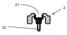
- Figure 5 is a top perspective view of the housing element (2) of the device (6).
- Figure 6 is a bottom perspective view of the housing element (2).
- Fig. 7 is a right side view of the housing element (2) shown in Fig. 5.
- Figure 8 is a perspective view of the device (6) composed of the retaining (1) and housing (2) elements.
- Figure 9 is a top perspective view of the device (6) with the retaining (1) and housing (2) elements coupled, enclosing a drop (3) between them.
- Figure 10 is a bottom perspective view of the device (6) with the retaining (1) and housing (2) elements coupled, enclosing a drop (3) between them.
- Figure 11 is a left side view of the device (6) shown in Figure 9.
- the present invention relates to a cable retaining device (6) comprising two elements, a retaining element (1) and a housing element (2).
- the housing element (2) is an elongate body (20) provided with a channel (21), particularly centered on one side of the body (20), said channel (21) extending along the elongate body (20). ) going from one end of the body to the other (20).
- the channel (21) of the housing element (2) has a locking system formed by grooved faces that secure the optical drop (3) by locking it.
- the retaining element (1) is an elongated body (10) in the form of a rail suitable for receiving the housing element (20) from the housing (2) by insertion into the body (10).
- the body (10) of the retaining element (1) has a substantially "C” shaped cross-section lying with a centralized inner shoulder (11), and the edges (12) of the "C” have shoulder (121) facing towards each other. the inner part of the elongate body (10), which ensures better attachment of the housing element (2) to the retaining element (1).
- the cross-section of the elongate body (10) is complementary to that of the housing element (20) body (2) with the exception of the shoulder (11) which is spaced from the channel (21), forming a space between them upon insertion of the body (20) of the housing element (2) in the body (10) of the retaining element (1).
- Said space is sufficiently smaller than the space occupied by an optical drop (3), so as to allow the positioning of the optical drop (3) in the channel (21) and its retention to the device (6) when inserting the housing element ( 2) in the retaining element (1), being retained in said space, pressed by the shoulder (11) and the channel (21).
- Said retaining element (1) comprises a shoulder (13) from its upper face which is provided with a hole (131) used to receive a hook (5) (see figures 9 and 10) which assists in securing the device ( 6) on post pulleys or guide rings (not shown).
- the retaining element (1) further comprises a housing (14) from the shoulder (13), the housing having an opening (141) (see figure 3).
- Said housing element (2) further comprises a cable (23) from one end of the body (20), and at the opposite end of the cable (23) there is a shoulder (24) in the form of a diametrical widening. of the cable (23), suitable for coupling in the housing (14) through the opening (141) of the retaining element (1), which allows to secure the housing element (2) to the retaining element (1), facilitating the use device (6) when attached to an optical drop (3).
- the housing element (2) further comprises a protrusion (22) on its lower face which is used to be depressed by the user when inserting and sliding the housing element (2) into the retaining element (1).
- the optical drop (3) is first positioned in the channel (21) of the housing element (2), after which the inserting element is inserted. housing (2) on the retaining element (1) until the drop (3) is retained within the device (6).
- the optical drop (3) is pressed between the grooves of the channel (21) and the shoulder ( 11), and thus is anchored to the device (6) by the pressure exerted along and around the entire outer surface of the optical drop (3) retained on the device (6).
Landscapes
- Physics & Mathematics (AREA)
- General Physics & Mathematics (AREA)
- Optics & Photonics (AREA)
- Light Guides In General And Applications Therefor (AREA)
- Cable Accessories (AREA)
Abstract
La présente demande de brevet concerne un dispositif de retenue de câbles (6) utile pour la retenue, la suspension et l'ancrage de câbles à fibre optique, du type drop optique (3), et comprenant un élément de retenue (1) et un élément de réception (2) qui, une fois accouplés, retiennent un drop (3) entre eux, permettant sa manipulation.
Priority Applications (5)
| Application Number | Priority Date | Filing Date | Title |
|---|---|---|---|
| EP18793749.5A EP3620835B1 (fr) | 2017-05-02 | 2018-04-27 | Dispositif de retenue de câbles |
| CA3062367A CA3062367C (fr) | 2017-05-02 | 2018-04-27 | Dispositif de retenue de cables |
| US16/610,832 US10955637B2 (en) | 2017-05-02 | 2018-04-27 | Cable-retention device |
| ES18793749T ES2928994T3 (es) | 2017-05-02 | 2018-04-27 | Dispositivo de retención de cable |
| DO2019000281A DOP2019000281A (es) | 2017-05-02 | 2019-11-05 | Dispositivo de retención de cables |
Applications Claiming Priority (2)
| Application Number | Priority Date | Filing Date | Title |
|---|---|---|---|
| BR202017009256-4U BR202017009256Y1 (pt) | 2017-05-02 | 2017-05-02 | Dispositivo de retenção de cabos |
| BR2020170092564 | 2017-05-02 |
Publications (1)
| Publication Number | Publication Date |
|---|---|
| WO2018201211A1 true WO2018201211A1 (fr) | 2018-11-08 |
Family
ID=64015912
Family Applications (1)
| Application Number | Title | Priority Date | Filing Date |
|---|---|---|---|
| PCT/BR2018/050136 WO2018201211A1 (fr) | 2017-05-02 | 2018-04-27 | Dispositif de retenue de câbles |
Country Status (9)
| Country | Link |
|---|---|
| US (1) | US10955637B2 (fr) |
| EP (1) | EP3620835B1 (fr) |
| AR (1) | AR111654A1 (fr) |
| BR (1) | BR202017009256Y1 (fr) |
| CA (1) | CA3062367C (fr) |
| DO (1) | DOP2019000281A (fr) |
| ES (1) | ES2928994T3 (fr) |
| PT (1) | PT3620835T (fr) |
| WO (1) | WO2018201211A1 (fr) |
Families Citing this family (3)
| Publication number | Priority date | Publication date | Assignee | Title |
|---|---|---|---|---|
| BR202017009256Y1 (pt) * | 2017-05-02 | 2020-03-24 | Valcir Fabris | Dispositivo de retenção de cabos |
| USD958750S1 (en) * | 2020-09-30 | 2022-07-26 | Molex, Llc | Connector |
| EP4252058A1 (fr) * | 2020-11-30 | 2023-10-04 | Corning Research & Development Corporation | Mécanisme de rupture de câble d'urgence |
Citations (6)
| Publication number | Priority date | Publication date | Assignee | Title |
|---|---|---|---|---|
| GB2178602A (en) * | 1985-07-26 | 1987-02-11 | Pfisterer Elektrotech Karl | Insulated anchor or suspension clamp |
| JPH08334630A (ja) * | 1995-06-09 | 1996-12-17 | Furukawa Electric Co Ltd:The | 光ファイバケーブルの緊線方法 |
| US5647046A (en) * | 1995-11-20 | 1997-07-08 | Alcoa Fujikura Limited | Wedge deadend to support aerial cables |
| FR2760144A1 (fr) * | 1997-02-24 | 1998-08-28 | France Telecom | Pince pour la fixation de cables dans des installations aeriennes |
| US6389213B1 (en) * | 2000-02-12 | 2002-05-14 | Alcoa Fujikura Limited | Deadend wedge design |
| CN206038986U (zh) * | 2016-08-10 | 2017-03-22 | 成都亨通光通信有限公司 | 一种轻型绝缘多向8字型自承光缆固定金具 |
Family Cites Families (11)
| Publication number | Priority date | Publication date | Assignee | Title |
|---|---|---|---|---|
| FR2820250B1 (fr) * | 2001-01-29 | 2003-04-11 | Fci Electr France | Pince d'ancrage pour ligne aerienne |
| US6581251B2 (en) * | 2001-10-26 | 2003-06-24 | Allied Bolt, Inc. | Drop wire clamp |
| US6732981B2 (en) * | 2002-08-22 | 2004-05-11 | Senior Industries, Inc. | Drop wire clamp |
| US7367534B2 (en) * | 2004-04-01 | 2008-05-06 | Senior Industries, Inc. | Drop wire clamp |
| US20100092147A1 (en) * | 2006-10-16 | 2010-04-15 | Christophe Desard | Optical fiber cable retention device |
| MX2010011062A (es) * | 2008-04-08 | 2010-11-10 | Afl Telecommunications Llc | Extremo muerto de cuña para soportar alambre de conexion a tierra optico. |
| MY179110A (en) * | 2013-02-28 | 2020-10-28 | Fujikura Ltd | Optical fiber splicing tool and optical fiber splicing method |
| US10095001B2 (en) * | 2016-07-29 | 2018-10-09 | Hubbell Incorporated | Spring assist cable clamps |
| US10338335B2 (en) * | 2016-11-16 | 2019-07-02 | Corning Research & Development Corporation | Mid-span clamp for aerial fiber optical cable system |
| US11105996B2 (en) * | 2017-02-27 | 2021-08-31 | CommScope Connectivity Belgium BVBA | Fiber optic cable fixation device and fiber optic cable mounting system comprising same |
| BR202017009256Y1 (pt) * | 2017-05-02 | 2020-03-24 | Valcir Fabris | Dispositivo de retenção de cabos |
-
2017
- 2017-05-02 BR BR202017009256-4U patent/BR202017009256Y1/pt active IP Right Grant
-
2018
- 2018-04-26 AR ARP180101080A patent/AR111654A1/es active IP Right Grant
- 2018-04-27 EP EP18793749.5A patent/EP3620835B1/fr active Active
- 2018-04-27 CA CA3062367A patent/CA3062367C/fr active Active
- 2018-04-27 WO PCT/BR2018/050136 patent/WO2018201211A1/fr unknown
- 2018-04-27 ES ES18793749T patent/ES2928994T3/es active Active
- 2018-04-27 PT PT187937495T patent/PT3620835T/pt unknown
- 2018-04-27 US US16/610,832 patent/US10955637B2/en active Active
-
2019
- 2019-11-05 DO DO2019000281A patent/DOP2019000281A/es unknown
Patent Citations (6)
| Publication number | Priority date | Publication date | Assignee | Title |
|---|---|---|---|---|
| GB2178602A (en) * | 1985-07-26 | 1987-02-11 | Pfisterer Elektrotech Karl | Insulated anchor or suspension clamp |
| JPH08334630A (ja) * | 1995-06-09 | 1996-12-17 | Furukawa Electric Co Ltd:The | 光ファイバケーブルの緊線方法 |
| US5647046A (en) * | 1995-11-20 | 1997-07-08 | Alcoa Fujikura Limited | Wedge deadend to support aerial cables |
| FR2760144A1 (fr) * | 1997-02-24 | 1998-08-28 | France Telecom | Pince pour la fixation de cables dans des installations aeriennes |
| US6389213B1 (en) * | 2000-02-12 | 2002-05-14 | Alcoa Fujikura Limited | Deadend wedge design |
| CN206038986U (zh) * | 2016-08-10 | 2017-03-22 | 成都亨通光通信有限公司 | 一种轻型绝缘多向8字型自承光缆固定金具 |
Non-Patent Citations (1)
| Title |
|---|
| See also references of EP3620835A4 * |
Also Published As
| Publication number | Publication date |
|---|---|
| CA3062367A1 (fr) | 2019-11-26 |
| AR111654A1 (es) | 2019-08-07 |
| BR202017009256Y1 (pt) | 2020-03-24 |
| EP3620835A4 (fr) | 2021-01-20 |
| DOP2019000281A (es) | 2020-02-28 |
| ES2928994T3 (es) | 2022-11-24 |
| CA3062367C (fr) | 2023-01-24 |
| EP3620835B1 (fr) | 2022-08-03 |
| US20200073072A1 (en) | 2020-03-05 |
| EP3620835A1 (fr) | 2020-03-11 |
| US10955637B2 (en) | 2021-03-23 |
| PT3620835T (pt) | 2022-10-03 |
| BR202017009256U2 (pt) | 2018-11-21 |
Similar Documents
| Publication | Publication Date | Title |
|---|---|---|
| WO2018201211A1 (fr) | Dispositif de retenue de câbles | |
| KR101683146B1 (ko) | 원터치식 철근 커플러 | |
| US7367534B2 (en) | Drop wire clamp | |
| BR112019028047A2 (pt) | conjuntos de múltiplas portas que incluem recursos de retenção | |
| US8584323B2 (en) | Device for securing resilient cord | |
| US11314030B2 (en) | Cable fixation devices and methods | |
| BR0201727A (pt) | Conector com mola para conexão elétrica | |
| ITFI20090152A1 (it) | Morsetto per connessioni elettriche | |
| NZ520952A (en) | Suspending equipment | |
| KR20180061129A (ko) | 장거리 케이블 체인용 케이블 지지블록 | |
| KR102151253B1 (ko) | 건축용 단열재 고정장치 | |
| ES2218371T3 (es) | Terminal para elemento de tension flexible plano. | |
| CN106163877A (zh) | 用于将装置可拆卸地安置在机动车座椅的两个间隔的头枕杆上的固定装置 | |
| ES2235071T3 (es) | Suspension de material. | |
| MXPA97003709A (es) | Separador de soporte para cable aereo. | |
| WO2013133600A1 (fr) | Lunettes de plongée comprenant un pont de nez réglable | |
| US1928622A (en) | Conductor and ground wire support | |
| CN209115003U (zh) | 一种淋浴房用缓冲器的新型安装结构 | |
| EP3171471A1 (fr) | Adaptateur pour chemin de câbles, et système de répartition de câbles | |
| CN213367279U (zh) | 一种通信工程电缆安装锁环 | |
| US1679969A (en) | Detachable connection for the cables of lightning-arrester systems | |
| KR101668108B1 (ko) | 통신용 케이블 행거 | |
| US1257135A (en) | Guying-pole. | |
| ES2251437T3 (es) | Dispositivo de suspension para linea electrica. | |
| CN211790429U (zh) | 一种耐张串更换装置 |
Legal Events
| Date | Code | Title | Description |
|---|---|---|---|
| 121 | Ep: the epo has been informed by wipo that ep was designated in this application |
Ref document number: 18793749 Country of ref document: EP Kind code of ref document: A1 |
|
| NENP | Non-entry into the national phase |
Ref country code: DE |
|
| ENP | Entry into the national phase |
Ref document number: 2018793749 Country of ref document: EP Effective date: 20191202 |