WO2018199181A1 - Matériau de rétrécissement d'espace libre, composite de matériau de rétrécissement d'espace libre et article l'utilisant - Google Patents
Matériau de rétrécissement d'espace libre, composite de matériau de rétrécissement d'espace libre et article l'utilisant Download PDFInfo
- Publication number
- WO2018199181A1 WO2018199181A1 PCT/JP2018/016855 JP2018016855W WO2018199181A1 WO 2018199181 A1 WO2018199181 A1 WO 2018199181A1 JP 2018016855 W JP2018016855 W JP 2018016855W WO 2018199181 A1 WO2018199181 A1 WO 2018199181A1
- Authority
- WO
- WIPO (PCT)
- Prior art keywords
- gap
- polymer
- polymer chain
- narrowing material
- gap narrowing
- Prior art date
Links
- 0 *C(C1*=C)N(*)C(*)(C2CCCCCCC2)N1O* Chemical compound *C(C1*=C)N(*)C(*)(C2CCCCCCC2)N1O* 0.000 description 1
Images


Classifications
-
- C—CHEMISTRY; METALLURGY
- C08—ORGANIC MACROMOLECULAR COMPOUNDS; THEIR PREPARATION OR CHEMICAL WORKING-UP; COMPOSITIONS BASED THEREON
- C08F—MACROMOLECULAR COMPOUNDS OBTAINED BY REACTIONS ONLY INVOLVING CARBON-TO-CARBON UNSATURATED BONDS
- C08F292/00—Macromolecular compounds obtained by polymerising monomers on to inorganic materials
-
- C—CHEMISTRY; METALLURGY
- C08—ORGANIC MACROMOLECULAR COMPOUNDS; THEIR PREPARATION OR CHEMICAL WORKING-UP; COMPOSITIONS BASED THEREON
- C08L—COMPOSITIONS OF MACROMOLECULAR COMPOUNDS
- C08L101/00—Compositions of unspecified macromolecular compounds
-
- C—CHEMISTRY; METALLURGY
- C09—DYES; PAINTS; POLISHES; NATURAL RESINS; ADHESIVES; COMPOSITIONS NOT OTHERWISE PROVIDED FOR; APPLICATIONS OF MATERIALS NOT OTHERWISE PROVIDED FOR
- C09K—MATERIALS FOR MISCELLANEOUS APPLICATIONS, NOT PROVIDED FOR ELSEWHERE
- C09K3/00—Materials not provided for elsewhere
- C09K3/12—Materials for stopping leaks, e.g. in radiators, in tanks
-
- C—CHEMISTRY; METALLURGY
- C10—PETROLEUM, GAS OR COKE INDUSTRIES; TECHNICAL GASES CONTAINING CARBON MONOXIDE; FUELS; LUBRICANTS; PEAT
- C10M—LUBRICATING COMPOSITIONS; USE OF CHEMICAL SUBSTANCES EITHER ALONE OR AS LUBRICATING INGREDIENTS IN A LUBRICATING COMPOSITION
- C10M107/00—Lubricating compositions characterised by the base-material being a macromolecular compound
-
- F—MECHANICAL ENGINEERING; LIGHTING; HEATING; WEAPONS; BLASTING
- F16—ENGINEERING ELEMENTS AND UNITS; GENERAL MEASURES FOR PRODUCING AND MAINTAINING EFFECTIVE FUNCTIONING OF MACHINES OR INSTALLATIONS; THERMAL INSULATION IN GENERAL
- F16C—SHAFTS; FLEXIBLE SHAFTS; ELEMENTS OR CRANKSHAFT MECHANISMS; ROTARY BODIES OTHER THAN GEARING ELEMENTS; BEARINGS
- F16C33/00—Parts of bearings; Special methods for making bearings or parts thereof
- F16C33/02—Parts of sliding-contact bearings
- F16C33/04—Brasses; Bushes; Linings
- F16C33/20—Sliding surface consisting mainly of plastics
-
- C—CHEMISTRY; METALLURGY
- C08—ORGANIC MACROMOLECULAR COMPOUNDS; THEIR PREPARATION OR CHEMICAL WORKING-UP; COMPOSITIONS BASED THEREON
- C08F—MACROMOLECULAR COMPOUNDS OBTAINED BY REACTIONS ONLY INVOLVING CARBON-TO-CARBON UNSATURATED BONDS
- C08F2438/00—Living radical polymerisation
- C08F2438/01—Atom Transfer Radical Polymerization [ATRP] or reverse ATRP
Definitions
- the present invention relates to a gap narrowing material, a gap narrowing material composite, and an article using them.
- a combination portion formed by combining a pair of members that fit into each other such as a structure including a combination hole and a shaft fitted into the combination hole, is used in various devices.
- a pair of members that support each other and maintain the positional relationship between the pair of members and other members, or one member moves relative to the other member Contributes to the mechanical movement of
- some of these joints require that a gap between a pair of members mating with each other be sealed against a liquid or gas.
- one member is the other.
- various seal mechanisms have been developed for sealing between a pair of members in a mating member.
- a mechanical device that handles a fluid such as a pump, a stirrer, or a compressor has a shaft that transmits power of a drive unit to mechanical parts in a housing.
- the shaft is inserted into a mating hole formed in the housing, and rotates or reciprocates in the axial direction in the mating hole by the power of the drive unit. It is necessary to prevent the fluid in the housing from leaking out without interfering with the movement of the shaft in the joint portion composed of such a joint hole and a shaft.
- the mechanical seal which combined is used.
- a mechanical seal mechanism such as a mechanical seal is difficult to adjust due to its complicated structure. For example, a rotating ring attached to a shaft is sufficiently inclined to a fixed ring attached to a housing. Problems such as inability to obtain a sealing property and problems in shaft movement are likely to occur.
- a film having a relatively low coefficient of friction on the surfaces of the pair of members that constitute the mating portion, it is possible to narrow the gap between the pair of members and ensure the fluid tightness. It is being considered.
- Such membranes eliminate the need for mechanical adjustments such as mechanical seals, increase the durability by selecting membrane materials, eliminate maintenance, and use inexpensive membrane materials to maintain maintenance costs. Can be suppressed.
- a film having such a low friction coefficient a film made of hard DLC (Diamond Like Carbon) or a film formed by applying a self-lubricating resin such as polyoxymethylene can be considered.
- a hard material such as DLC is difficult to absorb a dimensional error because it is not flexible, and high dimensional accuracy and high mechanical accuracy are required for a pair of members in order to fill the gap with the film. For this reason, there is a disadvantage that the cost is rather increased.
- a film formed by applying a resin has a relatively low dimensional accuracy and mechanical accuracy of the joint member because the resin is relatively inexpensive and the dimensional error can be absorbed by the flexibility of the film. There is an advantage of being good.
- such a resin coating film is inevitably inferior in abrasion resistance, and particularly when it is slid on a member under conditions where there is no escape, such as a gap in a mating member, large damage is caused by the strong force generated there. As a result, there arises a problem that the function as the sealing material is lost.
- the sealing material disposed in the gap between the mating members is required to have excellent sealing properties and mechanical characteristics that do not disturb the relative movement of the pair of members and withstand sliding while receiving a strong force. In fact, no sealant that meets such requirements has been found so far.
- Patent Document 1 Japanese Patent No. 3422463 (Japanese Patent Laid-Open No. 11-263819)
- Patent Document 2 JP 2006-316169 JP
- Patent Document 3 JP 2014-169787 JP
- the present inventors have studied the performance of the polymer brush from various viewpoints.
- the polymer brush When the polymer brush is disposed in the gap (gap) of the joint portion to impregnate the liquid, the polymer brush Has been found to swell greatly, narrowing the gap space, and effectively suppressing fluid leakage through the gap.
- the above-mentioned patent documents describe the low friction and lubricity of the polymer brush, they do not describe the effect of suppressing fluid leakage. From these documents, the polymer brush is a fluid. It is unpredictable to have an effect of suppressing leakage of water.
- the present inventors have further investigated the usefulness of the polymer brush and a polymer material having a common structure as the gap narrowing material, effectively improving the sealing performance against the fluid in the gap, and To find a material that does not interfere with the relative movement of the members forming the gap, and to provide an article in which fluid leakage from the gap can be suppressed and the member forming the gap can operate smoothly. Aimed at research.
- a brush-like polymer chain assembly composed of a plurality of polymer chains fixed to a base material is excellent as a gap narrowing material. It was found to have the properties.
- this polymer chain assembly is arranged on the surfaces of the pair of members forming the gap, the fluid leakage through the gap is effectively suppressed and the gap is formed. It has been found that a smooth operation can be obtained when one member is moved relative to the other member.
- the present invention has been proposed based on these findings, and specifically has the following configuration.
- a gap narrowing material including a brush-like polymer chain assembly composed of a plurality of polymer chains fixed to a substrate.
- the base material is at least one member of a joining member configured by joining a pair of members to each other, and the plurality of polymer chains are at least the surface of the one member.
- the gap narrowing material according to [2] which is fixed to a surface of the pair of members facing the other member.
- a gap narrowing material composite comprising the gap narrowing material according to any one of [1] to [12] and a base material on which the gap narrowing material is fixed.
- the base material is at least one member of a sheet, fine particles, fibers, or a combination member formed by combining a pair of members with each other. .
- h represents a radial gap ( ⁇ m)
- Q is a case where a gap narrowing material is fixed to the surface of a member forming the gap and then liquid is placed on the opening of the gap.
- a represents a coefficient (mL / second ⁇ ⁇ m 3 ) determined from the experimental conditions (gap differential pressure, liquid viscosity, gap length, gap outer diameter)
- b represents the effective film thickness of the gap narrowing material in the gap.
- the gap space can be narrowed, and fluid leakage through the gap can be effectively suppressed, and one member forming the gap is the other member. Smooth movement can be obtained when relative movement is performed.
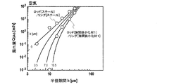
- N, N-diethyl-N which is an ionic liquid
- the radial gap h 6 is a graph showing the relationship of leakage amount of -methyl-N- (2-methoxyethyl) ammonium-bis (trifluoromethanesulfonyl) imide (DEME-TFSI).
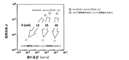
- the friction coefficient ⁇ between the radial gap h and the rod and the ring is It is a graph which shows a relationship. Graph showing the relationship between the amount of leakage of the ionic liquid DEME-TFSI and the friction coefficient for the system in which the gap narrowing material 1 is applied to both the rod and the ring and the system in which the gap narrowing material is not applied to the rod and the ring It is.
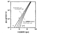
- a graph showing the relationship between the radial gap h and the leakage amount of n-hexadecane for the system in which the gap narrowing material 1 is applied to both the rod and the ring, and the system in which the gap narrowing material is not applied to the rod and the ring. is there.
- a numerical range expressed using “to” means a range including numerical values described before and after “to” as a lower limit value and an upper limit value.
- (meth) acrylic acid means both acrylic acid and methacrylic acid.
- the gap narrowing material of the present invention includes a brush-like polymer chain aggregate composed of a plurality of polymer chains fixed to a substrate.
- the “gap narrowing material” in the present invention is a material that is fixed to the surface of a member forming the gap, narrows the space of the gap, and exhibits an action of increasing the sealing performance against the fluid in the gap.
- narrowing the gap includes both the fact that the gap narrowing material is present and the gap space is narrowed and the gap space is completely filled with the gap narrowing material.
- “Sealing property” refers to the performance of suppressing fluid from leaking to the other through the gap when the fluid is supplied to one opening of the gap.
- Fluid refers to liquid and gas
- the gap narrowing material of the present invention may enhance the sealing performance against either liquid or gas, or increase the sealing performance against both liquid and gas. You may do.
- the polymer chain assembly used in the present invention has a brush-like shape as a whole, and is equipped with a tribology (Soft) and toughness (Resilient) derived from ultra-low friction properties (Tribology). ) System material (hereinafter also referred to as “SRT material”), which is completely different from an organic film formed by simply applying a polymer solution.
- each polymer chain expands and swells, forming a large amount of indentation and a high compressive modulus, and forming a low friction layer. Therefore, when this polymer chain aggregate is impregnated with a liquid substance and disposed in the gap, the space of the gap is narrowed and the sealing performance against the fluid is effectively improved.
- the polymer chain assembly layer absorbs the error even when the dimensional accuracy and mechanical accuracy of the member forming the gap are low due to the large indentation amount and compression elastic modulus. The space can be effectively narrowed.
- this polymer chain assembly layer has low friction and lubricity, so that even when one member forming a gap moves relative to the other member, the relative motion It is possible to contribute to the realization of smooth operation without disturbing the above. Furthermore, the polymer chain assembly layer is not easily worn even when the relative movement of the members forming the gap is repeated because each polymer chain is fixed to the substrate. Show excellent durability. Therefore, this polymer chain aggregate can be effectively used as a gap narrowing material.
- the polymer chain assembly included in the gap narrowing material of the present invention will be described.
- the polymer chain aggregate is composed of a plurality of polymer chains fixed to a base material, and has a brush-like shape as a whole.
- the “polymer chain” in the present invention refers to a molecule or a molecular part having a structure in which a plurality of structural units are linearly linked.
- the plurality of polymer chains constituting the polymer chain assembly may be the same as or different from each other.
- the polymer chain only needs to have a structure in which a plurality of structural units are linearly linked, and may have a side chain or a branched structure.
- a cross-linked structure may be formed between the polymer chain and the base material.
- the polymer chain constituting the polymer chain assembly may be a non-electrolyte polymer or an electrolyte polymer, and may be a hydrophobic polymer or a hydrophilic polymer.
- non-electrolyte polymer poly (methyl methacrylate) (PMMA) or the like is preferable.
- electrolyte polymer poly (sodium sulfonated glycidyl methacrylate) (PSGMA) or ionic liquid type polymer is used. preferable.
- hydrophobic polymer poly (alkyl (meth) acrylate) such as poly (methyl methacrylate) is preferable.
- hydrophilic polymer poly (hydroxyalkyl (meth) acrylate) such as poly (2-hydroxyethyl methacrylate) (PHEMA), poly (meth) acrylate having a polyethylene glycol side chain, and the like are preferable.
- the hydrophilic polymer may be synthesized using a hydrophilic monomer, or may be synthesized by synthesizing a polymer using a hydrophobic monomer and then introducing a hydrophilic group into the polymer.
- the polymer chain may be a homopolymer obtained by polymerizing one kind of monomer or a copolymer obtained by polymerizing two or more kinds of monomers.
- Examples of the copolymer include a random copolymer, a block copolymer, and a gradient copolymer.
- the monomer used for the production of the polymer chain is preferably a monomer capable of binding the polymer chain obtained by the polymerization as a graft chain to the substrate.
- a monomer having at least one addition polymerizable double bond examples include a monomer having at least one addition polymerizable double bond, and a monofunctional monomer having one addition polymerizable double bond is preferable.
- the monofunctional monomer having one addition polymerizable double bond include (meth) acrylic acid monomers and styrene monomers.
- (Meth) acrylic acid monomers include (meth) acrylic acid, methyl (meth) acrylate, ethyl (meth) acrylate, propyl (meth) acrylate, isopropyl (meth) acrylate, butyl (meth) acrylate, isobutyl (meth) Preferred are acrylate, tert-butyl (meth) acrylate, pentyl (meth) acrylate, hexyl (meth) acrylate, cyclohexyl (meth) acrylate, and the like.
- (meth) acrylic acid monomers heptyl (meth) acrylate, octyl (meth) acrylate, 2-ethylhexyl (meth) acrylate, nonyl (meth) acrylate, decyl (meth) acrylate, dodecyl (meth) acrylate, phenyl (meth) ) Acrylate, toluyl (meth) acrylate, benzyl (meth) acrylate and the like are also preferred.
- (meth) acrylic acid monomers 2-methoxyethyl (meth) acrylate, 3-methoxypropyl (meth) acrylate, 3-methoxybutyl (meth) acrylate, 2-hydroxyethyl (meth) acrylate, 2-hydroxypropyl ( Also preferred are (meth) acrylate, stearyl (meth) acrylate, glycidyl (meth) acrylate, 3-ethyl-3- (meth) acryloyloxymethyloxetane and the like.
- (meth) acrylic acid monomers 2- (meth) acryloyloxyethyl isocyanate, (meth) acrylate-2-aminoethyl, 2- (2-bromopropionyloxy) ethyl (meth) acrylate, 2- (2-bromo Isobutyryloxy) ethyl (meth) acrylate and the like are also preferable.
- (meth) acrylic acid monomers 1- (meth) acryloxy-2-phenyl-2- (2,2,6,6-tetramethyl-1-piperidinyloxy) ethane, 1- (4-(( 4- (Meth) acryloxy) ethoxyethyl) phenylethoxy) piperidine, ⁇ - (methacryloyloxypropyl) trimethoxysilane and the like are also preferable.
- (meth) acrylic acid monomer 3-[(3,5,7,9,11,13,15-heptaisobutylpentacyclo [9.5.1.13,9.15,15.17,13] octasiloxane-1-yloxy) dimethyl Silyl] propyl (meth) acrylate, 3-[(3,5,7,9,11,13,15-heptaisooctylpentacyclo [9.5.1.13,9.15,15.17,13] octasiloxane-1-yloxy) dimethyl Silyl] propyl (meth) acrylate and the like are also preferable.
- (meth) acrylic acid monomers 2-perfluoromethyl-2-perfluoroethylethyl (meth) acrylate, 2-perfluorohexylethyl (meth) acrylate, 2-perfluorodecylethyl (meth) acrylate, 2-perfluorohexadecylethyl (Meth) acrylate and the like are also preferable.
- Styrene monomers include styrene, vinyltoluene, ⁇ -methylstyrene, p-chlorostyrene, p-chloromethylstyrene, m-chloromethylstyrene, o-aminostyrene, p-styrene chlorosulfonic acid, styrenesulfonic acid and its Salt, vinylphenylmethyldithiocarbamate, 2- (2-bromopropionyloxy) styrene, 2- (2-bromoisobutyryloxy) styrene and the like are preferable.
- styrene monomers 1- (2-((4-vinylphenyl) methoxy) -1-phenylethoxy) -2,2,6,6-tetramethylpiperidine, 1- (4-vinylphenyl) -3,5 , 7,9,11,13,15-heptaethylpentacyclo [9.5.1.13,9.15,15.17,13] octasiloxane, 1- (4-vinylphenyl) -3,5,7,9,11,13, 15-heptaisobutylpentacyclo [9.5.1.13, 9.15, 15.17,13] octasiloxane and the like are also preferable.
- styrenic monomer 1- (4-vinylphenyl) -3,5,7,9,11,13,15-heptaisooctylpentacyclo [9.5.1.13,9.15,15.17,13] octasiloxane, 1- ( 4-vinylphenyl) -3,5,7,9,11,13,15-heptacyclopentylpentacyclo [9.5.1.13,9.15,15.17,13] octasiloxane, 1- (4-vinylphenyl) -3,5 , 7,9,11,13,15-heptaphenylpentacyclo [9.5.13.13,9.15,15.17,13] octasiloxane and the like are also preferable.
- the monofunctional monomer which has one addition polymerizable double bond illustrated below can also be used for the production
- monofunctional monomers having one addition polymerizable double bond fluorine-containing vinyl monomers (perfluoroethylene, perfluoropropylene, vinylidene fluoride, etc.), silicon-containing vinyl monomers (vinyltrimethoxysilane, vinyltriethoxysilane) Etc.), maleic anhydride, maleic acid, monoalkyl esters and dialkyl esters of maleic acid, fumaric acid, monoalkyl esters and dialkyl esters of fumaric acid, and the like are also preferred.
- maleimide monomers maleimide, methylmaleimide, ethylmaleimide, propylmaleimide, butylmaleimide, hexylmaleimide, octylmaleimide, dodecylmaleimide, stearylmaleimide, phenylmaleimide) Cyclohexyl maleimide, etc.
- maleimide monomers maleimide, methylmaleimide, ethylmaleimide, propylmaleimide, butylmaleimide, hexylmaleimide, octylmaleimide, dodecylmaleimide, stearylmaleimide, phenylmaleimide
- Cyclohexyl maleimide etc.
- Monofunctional monomers having one addition-polymerizable double bond include nitrile group-containing monomers (acrylonitrile, methacrylonitrile, etc.), amide group-containing monomers (acrylamide, methacrylamide, etc.), vinyl ester monomers (vinyl acetate) , Vinyl propionate, vinyl pivalate, vinyl benzoate, vinyl cinnamate, etc.) are also preferred.
- Monofunctional monomers having one addition-polymerizable double bond include olefins (ethylene, propylene, etc.), conjugated diene monomers (butadiene, isoprene, etc.), vinyl halides (vinyl chloride, etc.), vinylidene halides (Vinylidene chloride and the like), allyl halide (such as allyl chloride) and the like are also preferable.
- monofunctional monomers having one addition polymerizable double bond allyl alcohol, vinyl pyrrolidone, vinyl pyridine, N-vinyl carbazole, methyl vinyl ketone, vinyl isocyanate and the like are also preferable.
- a macromonomer having one polymerizable double bond in one molecule and having a main chain derived from styrene, (meth) acrylic acid ester, siloxane or the like is also preferable.
- hydrophobic monomer and a hydrophilic monomer for the production of the polymer chain.
- hydrophobic monomers examples include acrylic acid esters (eg, methyl acrylate, ethyl acrylate, propyl acrylate, butyl acrylate, cyclohexyl acrylate, hexafluoroisopropyl acrylate, etc. alkyl esters; aryl acrylates such as phenyl acrylate; benzyl acrylate, etc. Arylalkyl acrylate; alkoxyalkyl acrylate such as methoxymethyl acrylate) and the like are preferable.
- Methacrylic acid esters eg, methyl methacrylate, ethyl methacrylate, propyl methacrylate, butyl methacrylate, cyclohexyl methacrylate, hexafluoroisopropyl methacrylate, etc .
- alkyl methacrylates such as phenyl methacrylate
- aryl methacrylates such as benzyl methacrylate
- aryls such as benzyl methacrylate
- alkoxyalkyl methacrylate such as methoxymethyl methacrylate
- fumaric acid esters eg, alkyl esters of fumaric acid such as dimethyl fumarate, diethyl fumarate, diallyl fumarate, etc.
- maleic acid esters eg, dimethyl maleate, diethyl maleate, diallyl maleate, etc.
- alkyl esters of maleic acid and the like are particularly preferred.
- Hydrophobic monomers include itaconic acid esters (eg, itaconic acid alkyl esters), crotonic acid esters (eg, crotonic acid alkyl esters), methyl vinyl ether, ethoxyethyl vinyl ether, vinyl acetate, vinyl propionate, vinyl benzoate Styrene and the like are also preferable.
- As the hydrophobic monomer alkyl styrene, vinyl chloride, vinyl methyl ketone, vinyl stearate, vinyl alkyl ether, and a mixture thereof are also preferable.
- Hydrophilic monomers include hydroxy substituted alkyl acrylates (eg, 2-hydroxyethyl acrylate, 2-hydroxypropyl acrylate, 2-hydroxypropyl acrylate, 2,3-dihydroxypropyl acrylate, polyethoxyethyl acrylate, polyethoxypropyl acrylate, etc.) Etc. are preferred.
- Hydroxy monomers such as hydroxy-substituted alkyl methacrylates (eg, 2-hydroxyethyl methacrylate, 2-hydroxypropyl methacrylate, 2-hydroxypropyl methacrylate, 2,3-dihydroxypropyl methacrylate, polyethoxyethyl methacrylate, polyethoxypropyl methacrylate) Is also preferable.
- hydroxy-substituted alkyl methacrylates eg, 2-hydroxyethyl methacrylate, 2-hydroxypropyl methacrylate, 2-hydroxypropyl methacrylate, 2,3-dihydroxypropyl methacrylate, polyethoxyethyl methacrylate, polyethoxypropyl methacrylate
- hydrophilic monomer acrylamide, N-alkyl acrylamide (eg, N-methyl acrylamide, N, N-dimethyl acrylamide, etc.), N-alkyl methacrylamide (eg, N-methyl methacryl
- hydrophilic monomer polyethylene glycol monoacrylate, polyethylene glycol monomethacrylate, alkoxy polyethylene glycol acrylate, alkoxy polyethylene glycol methacrylate, phenoxy polyethylene glycol acrylate, phenoxy polyethylene glycol methacrylate, 2-glucosiloxyethyl methacrylate and the like are also preferable.
- hydrophilic monomer acrylic acid, methacrylic acid, fumaric acid, maleic acid, itaconic acid, crotonic acid, methacrylamide, allyl alcohol, N-vinylpyrrolidone and N, N-dimethylaminoethyl acrylate, and mixtures thereof are also preferable. .
- a monomer having a specific group in the side chain can also be suitably used.
- a monomer that has a carboxyl group or a group that can be easily converted to a carboxyl group salt in the side chain can be rendered hydrophilic by converting the side chain group of the resulting polymer chain to a carboxyl group or a salt of the carboxyl group. It is preferable in that it can be performed.
- the monomer having a carboxyl group or a group that can be easily converted into a carboxyl group salt in the side chain include 1-methoxyethyl acrylate, 1-ethoxyethyl acrylate, 1-propoxyethyl acrylate, and 1- (1-methylethoxy).
- Ethyl acrylate, 1-butoxyethyl acrylate, 1- (2-methylpropoxy) ethyl acrylate, 1- (2-ethylhexoxy) ethyl acrylate and the like are preferable.
- Monomers having a side chain having a carboxyl group or a group that can be easily converted to a salt of a carboxyl group include pyranyl acrylate, 1-methoxyethyl methacrylate, 1-ethoxyethyl methacrylate, 1-propoxyethyl methacrylate, 1- (1 -Methylethoxy) ethyl methacrylate, 1-butoxyethyl methacrylate, 1- (2-methylpropoxy) ethyl methacrylate, 1- (2-ethylhexoxy) ethyl methacrylate and the like are also preferable.
- Monomers having a side chain having a carboxyl group or a group that can be easily converted to a carboxyl group salt include pyranyl methacrylate, di-1-methoxyethyl malate, di-1-ethoxyethyl maleate, di-1-propoxyethyl Malate, di-1- (1-methylethoxy) ethyl maleate, di-1-butoxyethyl maleate, di-1- (2-methylpropoxy) ethyl maleate, dipyranyl malate and the like are also preferable.
- These monomers used for the production of polymer chains may be used alone or in combination of two or more.
- the polymer chain may be an electrolyte polymer such as an ionic liquid type polymer.
- an ionic liquid type polymer for example, the polymer etc. which superpose
- m represents an integer of 1 to 10
- n represents an integer of 1 to 5.
- R 1 represents a hydrogen atom or an alkyl group having 1 to 3 carbon atoms
- R 2 , R 3 and R 4 each independently represents an alkyl group having 1 to 5 carbon atoms.
- the alkyl group in R 2, R 3 and R 4, the carbon and hydrogen atoms, an oxygen atom, a sulfur atom may be substituted by 1 or more hetero atoms selected from fluorine atom, R 2 , R 3 and R 4 may be linked together to form a cyclic structure.
- Y represents a monovalent anion.
- the monovalent anion represented by Y is not particularly limited.
- BF 4 ⁇ , PF 6 ⁇ , AsF 6 ⁇ , SbF 6 ⁇ , AlCl 4 ⁇ , NbF 6 ⁇ , HSO 4 ⁇ , ClO 4 ⁇ , CH 3 SO 3 ⁇ , CF 3 SO 3 ⁇ , CF 3 CO 2 ⁇ , (CF 3 SO 2 ) 2 N ⁇ , Cl ⁇ , Br ⁇ , I ⁇ and the like can be mentioned.
- BF 4 ⁇ , PF 6 ⁇ , (CF 3 SO 2 ) 2 N ⁇ , CF 3 SO 3 ⁇ , or CF 3 CO 2 ⁇ is preferable.
- the ionic liquid type polymer is preferably a polymer obtained by polymerizing a compound represented by any one of the following general formulas (2) to (9) among the compounds represented by the general formula (1). .
- a crosslinked structure In the polymer chain assembly, a crosslinked structure may be formed between the polymer chains or between the polymer chain and the substrate. Thereby, the elastic modulus of the polymer chain aggregate can be controlled.
- the crosslinked structure formed between the polymer chains may be either a physical crosslinked structure or a chemically crosslinked structure.
- the cross-linked structure may be formed simultaneously with the polymerization reaction for generating the polymer chain, or may be formed after the polymer chain is generated.
- the formation of a cross-linked structure that is performed simultaneously with the polymerization reaction for generating the polymer chain can be carried out by adding a monofunctional monomer for generating the polymer chain to the polymerization reaction solution as well as a divinyl monomer such as ethylene glycol dimethacrylate.
- the formation of a crosslinked structure between the generated polymer chains or between the polymer chain and the base material is achieved by introducing a crosslinking group into the polymer chain using a monomer having a crosslinking group, And a reaction with a reactive group of another polymer chain, and a reaction of the crosslinking group with a reactive group of a substrate.
- the crosslinking group include an azide group and a halogen group (preferably a bromo group).
- a reactive group remaining at the end of the graft chain can be used as a crosslinking group.
- Whether or not the crosslinked structure is sufficiently formed can be determined by whether or not the solubility in a good solvent is lowered. For example, a free polymer formed by adding 1 mol% of a divinyl monomer to a monofunctional monomer swells in a good solvent but hardly dissolves. On the other hand, the polymer brush described below swells in a good solvent even if it is crosslinked.
- the polymer chains constituting the polymer chain aggregate are each fixed to a substrate.
- the substrate may be a carrier made of a substance different from the polymer chain assembly, or may be a polymer chain as a main chain in which the polymer chain is bound as a side chain.
- the polymer chain assembly constitutes a “polymer brush”.
- the base material is a carrier
- the whole of the main chain constituting the polymer chain and the polymer chain (side chain) bonded to the main chain is a “polymer having a bottle brush structure”.
- the formation method of the polymer chain aggregate is demonstrated about each of the polymer which has a polymer brush and a bottle brush structure.
- the polymer chain aggregate of a polymer brush can be obtained by a graft polymerization method in which a plurality of polymer chains are bonded to a substrate as graft chains.
- This graft polymerization can be performed by a Grafting-from method or a Grafting-to method, and among these, the Grafting-from method is preferably used.
- the Grafting-from method is a method in which a polymerization initiating group is introduced into a base material and a graft chain is grown from the polymerization initiating group.
- the Grafting-to method is a method in which a graft chain synthesized in advance is used as a base material. This is a method of bonding to the introduced reaction point.
- the polymer chain assembly has a hydrophobic part of a polymer having a hydrophobic block and a hydrophilic block (diblock copolymer) on the surface of a hydrophobic substrate or a hydrophobic substrate. It can also be obtained by a method of bonding.
- the diblock copolymer include a copolymer having a polymethyl methacrylate (PMMA) structure as a hydrophobic block and a poly (sodium sulfonated glycidyl methacrylate) (PSGMA) structure as a hydrophilic block.
- PMMA polymethyl methacrylate
- PSGMA poly (sodium sulfonated glycidyl methacrylate)
- Another polymer structure may be interposed between the PMMA structure and the PSGMA structure. For details of this method, see Nature, 425, 163-165 (2003) and the like.
- the polymer chain generation method used in the graft polymerization method is not particularly limited, but is preferably a radical polymerization method, more preferably a living radical polymerization method (LRP) method, and an atom transfer radical. More preferably, the polymerization (ATRP) method is used.
- the living radical polymerization method grafts various types of copolymers (eg, random copolymers, block copolymers, composition gradient copolymers, etc.) that can easily control the molecular weight and molecular weight distribution of polymer chains.
- a dense polymer brush described later can be produced by precisely controlling the density and thickness by using a high-pressure condition or an ionic liquid solvent.
- the graft polymerization method when the living radical polymerization method is used may be either the Grafting-from method or the Grafting-to method, but the Grafting-from method is preferable.
- the graft polymerization method combining the living radical polymerization method and the Grafting-from method reference can be made to JP-A-11-263819.
- the atom transfer radical polymerization method see J. Am. Chem. Soc., 117, 5614 (1995), Macromolecules, 28, 7901 (1995), Science, 272, 866 (1996), Macromolecules, 31, Reference can be made to 5934-5936 (1998).
- Polymer chains can also be generated by nitroxide-mediated polymerization (NMP), reversible addition-fragmentation chain transfer (RAFT) polymerization, reversible transfer catalytic polymerization (RTCP), reversible complexation-mediated polymerization (RCMP), etc. can do.
- NMP nitroxide-mediated polymerization
- RAFT reversible addition-fragmentation chain transfer
- RTCP reversible transfer catalytic polymerization
- RCMP complexation-mediated polymerization
- the catalyst used in the radical polymerization method may be any catalyst that can control radical polymerization, and is preferably a transition metal complex.
- the transition metal complex include metal complexes having a central metal of Group 7, 8, 9, 10, or 11 of the periodic table. Among them, copper complexes, ruthenium complexes, iron It is preferable to use a complex or a nickel complex, and it is more preferable to use a copper complex.
- the copper complex is preferably a complex of a monovalent copper compound and an organic ligand. Examples of the monovalent copper compound include cuprous chloride, cuprous bromide, cuprous iodide, cuprous cyanide, cuprous oxide, cuprous perchlorate and the like.
- organic ligands 2,2′-bipyridyl or a derivative thereof, 1,10-phenanthroline or a derivative thereof, polyamine (tetramethylethylenediamine, pentamethyldiethylenetriamine, hexamethyltris (2-aminoethyl) amine, etc.), L- And polycyclic alkaloids such as ( ⁇ )-spartein.
- a tristriphenylphosphine complex of divalent ruthenium chloride (RuCl 2 (PPh 3 ) 3 ) is also suitable as a catalyst. When a ruthenium compound is used as a catalyst, it is preferable to add an aluminum alkoxide as an activator.
- Bivalent iron bistriphenylphosphine complex FeCl 2 (PPh 3 ) 2
- divalent nickel bistriphenylphosphine complex NiCl 2 (PPh 3 ) 2
- divalent nickel bistributylphosphine complex NiBr 2 (PBu 3 ) 2
- PBu 3 nickel bistributylphosphine complex
- Solvents include hydrocarbon solvents (benzene, toluene, etc.), ether solvents (diethyl ether, tetrahydrofuran, diphenyl ether, anisole, dimethoxybenzene, etc.), halogenated hydrocarbon solvents (methylene chloride, chloroform, chlorobenzene, etc.), ketones Solvent (acetone, methyl ethyl ketone, methyl isobutyl ketone, etc.), alcohol solvent (methanol, ethanol, propanol, isopropanol, butyl alcohol, t-butyl alcohol, etc.), nitrile solvent (acetonitrile, propionitrile, benzonitrile, etc.), ester Solvents (ethyl acetate, butyl acetate, etc.), carbonate solvents (ethylene carbonate, propylene carbonate, etc.), amide solvents (N, N-dimethyl
- a polymerization initiating group that is a starting point of the polymerization reaction is introduced into the base material, and the above polymerization is initiated from this polymerization initiating group.
- the polymer chains are grafted using the method.
- the polymerization initiating group include a halogenated alkyl group and a halogenated sulfonyl group.
- the polymerization initiating group can accurately control the density of the graft chain (graft density) and the primary structure (molecular weight, molecular weight distribution, monomer arrangement pattern) of the polymer chain obtained by graft polymerization, it can be physically or chemically attached to the substrate surface. Are preferably bonded together.
- the method for introducing (bonding) the polymerization initiating group to the substrate surface include a chemical adsorption method and a Langmuir-Blodget (LB) method.
- introduction of a chlorosulfonyl group (polymerization initiating group) into the surface of a silicon wafer (base material) by chemical bonding may be performed by 2- (4-chlorosulfonylphenyl) ethyltrimethoxysilane or 2- (4-chlorosulfonylphenyl) ethyl. It can be performed by reacting trichlorosilane or the like with the oxide layer on the silicon wafer surface.
- a film forming material containing the polymerization initiating group is dissolved in an appropriate solvent (eg, chloroform, benzene, etc.).
- an appropriate solvent eg, chloroform, benzene, etc.
- a small amount of this solution is developed on a clean liquid surface, preferably on the surface of pure water, and then the solvent is evaporated or diffused into the adjacent aqueous phase to cause low density due to film-forming molecules on the water surface.
- the film is formed.
- the partition plate is mechanically swept over the water surface to reduce the surface area of the water surface on which the film-forming molecules are expanded, thereby compressing the membrane and increasing the density, thereby obtaining a dense monomolecular film on the water surface. .
- a group binding to the substrate and a group having affinity with the substrate at least one of a group binding to the substrate and a group having affinity with the substrate, a group binding to the polymerization initiating group, and a group having affinity with the polymerization initiating group are required. It is preferable to treat the substrate surface with a surface treating agent having one.
- This surface treatment agent may be a low molecular compound or a high molecular compound. Examples of the surface treatment agent include those represented by the following general formula (10).
- n is an integer of 1 to 10, preferably an integer of 3 to 8, and most preferably 6.
- R 1 , R 2 and R 3 each independently represents a substituent. At least one of R 1 , R 2 and R 3 is preferably an alkoxyl group or a halogen atom, and it is particularly preferred that all of R 1 , R 2 and R 3 are methoxy groups or ethoxy groups.
- R 4 and R 5 each independently represents a substituent. R 4 and R 5 are preferably each independently an alkyl group having 1 to 3 carbon atoms or an aromatic functional group, and most preferably, for example, both R 4 and R 5 are methyl groups.
- X represents a halogen atom and is preferably a bromine atom.
- silane coupling agent containing a polymerization initiation group (polymerization initiation group containing silane coupling agent) as a surface treating agent.
- surface treatment and introduction of a polymerization initiating group can be performed simultaneously.
- polymerization initiating group-containing silane coupling agent examples include (2-bromo-2-methyl) propionyloxyhexyltriethoxysilane (BHE), (2-bromo-2-methyl) propionyloxypropyltriethoxysilane (BPE).
- BHE (2-bromo-2-methyl) propionyloxyhexyltriethoxysilane
- BPE (2-bromo-2-methyl) propionyloxypropyltriethoxysilane
- a silane coupling agent that does not contain a polymerization initiator group for example, a known alkylsilane coupling agent is used. It is preferable to use together.
- the graft density can be freely changed by adjusting the ratio of the polymerization initiating group-containing silane coupling agent and the silane coupling agent not containing the polymerization initiating group.
- the silane coupling agent is a polymerization initiating group-containing silane coupling agent
- the polymer chain can be formed with a surface occupancy exceeding 3%. Can be grown.
- the polymerization initiating group-containing silane coupling agent is hydrolyzed in the presence of water to form silanol, and partially condensed to an oligomer state.
- this oligomer may be adsorbed on a base material such as silica by hydrogen bonding, and then dried to cause a dehydration condensation reaction to introduce a polymerization initiating group into the base material.
- a base material such as silica by hydrogen bonding
- the base material as a carrier for fixing the polymer chain can be appropriately selected from organic materials, inorganic materials, metal materials, and the like, and may be a hydrophobic base material or a hydrophilic base material.
- Solids used as a substrate include polyurethane materials, polyvinyl chloride materials, polystyrene materials, polyolefin materials, poly (methyl methacrylate), polyethylene terephthalate, cellulose acetate, paper, plastic laminate films, ceramics (eg, alumina ceramics) Composite ceramics such as bioceramics and zirconia-alumina composite ceramics).
- metals eg, iron, cast iron, steel, stainless steel, carbon steel, high carbon chromium bearing steel (SUJ2) and other iron alloys, aluminum, zinc, copper, titanium and other non-ferrous and non-ferrous metals Alloys
- metal-deposited paper silicon such as polycrystalline silicon, silicon oxide, silicon nitride, various glasses, quartz, and composite materials thereof.
- hydrophobic organic material used as the base material examples include polyolefin (eg, polyethylene, polypropylene, polyisobutylene, ethylene alpha olefin copolymer), silicon polymer, acrylic polymer (eg, polyacrylonitrile, polymethyl). Methacrylate, polyethyl methacrylate, polyethyl acrylate, etc.) and copolymers thereof.
- Hydrophobic organic materials used as substrates include fluoropolymers (eg, polytetrafluoroethylene, chlorotrifluoroethylene, fluorinated ethylene-propylene, polyvinyl fluoride, etc.), vinyl polymers (eg, polyvinyl chloride, polyvinyl) Methyl ether, polystyrene, polyvinyl acetate, polyvinyl ketone, etc.) and copolymers thereof are also preferred.
- fluoropolymers eg, polytetrafluoroethylene, chlorotrifluoroethylene, fluorinated ethylene-propylene, polyvinyl fluoride, etc.
- vinyl polymers eg, polyvinyl chloride, polyvinyl) Methyl ether, polystyrene, polyvinyl acetate, polyvinyl ketone, etc.
- copolymers thereof are also preferred.
- Hydrophobic organic materials used as base materials include vinyl monomer-containing copolymers (eg, ABS), natural and synthetic rubbers (eg, latex rubber, butadiene-styrene copolymer, polyisoprene, polybutadiene, butadiene-acrylonitrile) Copolymer, polychloroprene polymer, polyisobutylene rubber, ethylene-propylene diene copolymer, polyisobutylene-isoprene, and the like, and copolymers thereof are also preferred.
- vinyl monomer-containing copolymers eg, ABS
- natural and synthetic rubbers eg, latex rubber, butadiene-styrene copolymer, polyisoprene, polybutadiene, butadiene-acrylonitrile
- polychloroprene polymer polyisobutylene rubber, ethylene-propylene diene copolymer, polyisobutylene-isoprene,
- Hydrophobic organic materials used as base materials include polyurethane (eg, polyether urethane, polyester urethane, polycarbonate urethane, polysiloxane urethane, etc.), polyamide (eg, nylon 6, nylon 66, nylon 10, nylon 11, etc.), Polyester, epoxy polymer, cellulose, modified cellulose, and copolymers thereof are also preferable.
- polyurethane eg, polyether urethane, polyester urethane, polycarbonate urethane, polysiloxane urethane, etc.
- polyamide eg, nylon 6, nylon 66, nylon 10, nylon 11, etc.
- Polyester epoxy polymer, cellulose, modified cellulose, and copolymers thereof are also preferable.
- hydrophilic organic materials used as the base material include hydrophilic acrylic polymers (eg, polyacrylamide, poly-2-hydroxyethyl acrylate, poly-N, N-dimethylacrylamide, polyacrylic acid, polymethacrylic acid, etc.) , And copolymers thereof are preferred.
- hydrophilic organic materials used as substrates hydrophilic vinyl polymers (eg, poly-N-vinyl pyrrolidone, polyvinyl pyridine, etc.), polymaleic acid, poly-2-hydroxyethyl fumarate, maleic anhydride, polyvinyl alcohol , And copolymers thereof are also preferred.
- the form of the substrate is not particularly limited, and examples thereof include tubes, sheets, fibers, strips, films, plates, foils, membranes, pellets, powders, fine particles, molded products (eg, extrusion molded products, cast molded products, etc.).
- the member itself to which the gap narrowing material is applied may be used as the base material.
- fine particles made of the following materials for the fine-particle base material may be either an inorganic substance or an organic substance.
- silicon oxide such as silica
- noble metals such as Au, Ag, Pt, Pd, Ti, Zr, Ta, Sn, Zn, Cu, V, Sb, In, Hf, Y, Ce, Sc, La, Eu
- Transition metals such as Ni, Co and Fe
- inorganic substances such as oxides and nitrides thereof, and organic substances such as polymers
- organic substances such as polymers
- the average particle size of the fine particles used for the substrate is preferably 5 nm to 30 ⁇ m, more preferably 10 nm to 10 ⁇ m, and even more preferably 10 nm to 1 ⁇ m.
- the average particle size of the fine particles (composite fine particles) having polymer chain aggregates formed on the surface is preferably 10 nm to 30 ⁇ m, more preferably 10 nm to 20 ⁇ m, and further preferably 15 nm to 10 ⁇ m.
- the thickness is preferably 20 nm to 3 ⁇ m.
- the composite fine particles are preferably composite fine particles having a narrow particle size distribution with a particle size variation of 20% or less. Variations in the average particle size and particle size of the fine particles used for the substrate and the fine particles formed on the surface of the polymer chain aggregate can be measured by dynamic light scattering (DLS) or the like.
- DLS dynamic light scattering
- the fibers used for the substrate include commercially available fibers such as cotton, regenerated cellulose, polyethylene terephthalate, and polyvinyl alcohol, nanofibers obtained by electrospinning, cellulose nanofibers that are naturally available, and bacterial cellulose.
- the material of the base material is a member that applies a gap narrowing material, such as a member that constitutes an assembly member, a member that defines a fluid flow path, or a member that constitutes a sliding mechanism
- the material of the base material is , Metals (iron, stainless steel, carbon steel, cast iron, steel, nonferrous and nonferrous alloys such as aluminum, zinc, copper and titanium), resins (polyethylene, polyphenylene sulfide, polytetrafluoroethylene, etc.), A silicon wafer, glass, quartz or the like is preferable.
- the number average molecular weight (M n ) of the polymer chains constituting the polymer chain aggregate is preferably 500 to 10,000,000, more preferably 100,000 to 10,000,000.
- the molecular weight distribution index (PDI M w / M n ) in the polymer chain assembly is preferably 1.5 or less, more preferably 1.01 to 1.5.
- the gap narrowing material exhibits a more excellent gap narrowing action, mechanical properties, and low friction properties. Become a thing.
- the number average molecular weight (M n ) and molecular weight distribution index (M w / M n ) of a polymer chain are determined by size exclusion chromatography using a polymer chain cut out from a substrate by hydrofluoric acid treatment.
- the free polymer produced during the polymerization reaction of the polymer chain has a molecular weight equal to that of the polymer chain immobilized on the substrate
- the free polymer is subjected to size-exclusion chromatography to determine the number average molecular weight (M n ) and molecular weight distribution index (M w / M n ) may be measured and used as they are as the number average molecular weight (M n ) and molecular weight distribution index (M w / M n ) of the polymer chain. it can.
- the free polymer is analyzed by size exclusion chromatography to determine the number average molecular weight (M n ) and molecular weight distribution index (M w / M n ).
- M n number average molecular weight
- M w / M n molecular weight distribution index
- the size exclusion chromatography analysis is a calibration method using a homogenous monodisperse standard sample having a known molecular weight and an absolute molecular weight evaluation using a multi-angle light scattering detector.
- the density of the polymer chain in the polymer chain assembly varies depending on the type of the polymer chain and the liquid substance to be impregnated, but is preferably in the following range. Thereby, the gap narrowing material exhibits a more excellent gap narrowing action, mechanical characteristics, and low friction.
- the density of the polymer chain in the polymer chain assembly is preferably 0.1 chain / nm 2 or more, more preferably 0.15 chain / nm 2 or more, and further preferably Is 0.2 chain / nm 2 or more, even more preferably 0.3 chain / nm 2 or more, particularly preferably 0.4 chain / nm 2 or more, and most preferably 0.45 chain / nm 2 or more.
- the density of the polymer chain in the polymer chain assembly is preferably 0.04 chain / nm 2 or more, more preferably 0.06 chain / nm 2 or more, and further preferably Is 0.08 chain / nm 2 or more, even more preferably 0.12 chain / nm 2 or more, particularly preferably 0.16 chain / nm 2 or more, and most preferably 0.18 chain / nm 2 or more.
- the density of the polymer chain is preferably 0.02 chain / nm 2 or more, more preferably 0.03 chain / nm 2 or more, further preferably 0.04 chain / nm 2 or more, even more preferably 0.06 chain / nm 2 or more, particularly preferably. 0.08 chain / nm 2 or more, most preferably 0.09 chain / nm 2 or more.
- the measurement of the density of the polymer chain is carried out according to the graft density described in, for example, Macromolecules, 31, 5934-5936 (1998), Macromolecules, 33, 5608-5612 (2000), Macromolecules, 38, 2137-2142 (2005), etc. It can be performed according to the measuring method. Specifically, the density of the polymer chain (chain / nm 2 ) can be determined by measuring the graft amount (W) and the number average molecular weight (M n ) of the graft chain and using the following formula.
- graft density (chain / nm 2 ) W (g / nm 2 ) / M n ⁇ (Avocado number)
- W represents the graft amount
- M n represents the number average molecular weight.
- the graft amount (W) is measured by measuring the film thickness in the dry state, that is, the thickness of the grafted polymer chain layer in the dry state by an ellipsometry method. It can obtain
- the graft amount (W) can be measured by infrared absorption spectroscopy (IR), thermogravimetric loss measurement (TG), elemental analysis measurement, or the like.
- IR infrared absorption spectroscopy
- TG thermogravimetric loss measurement
- elemental analysis measurement or the like.
- M n number average molecular weight
- the surface occupancy ratio of the polymer chain on the surface of the substrate is preferably 3% or more, more preferably 5% or more, and more preferably 10% or more. Further preferred.
- the surface occupancy means the proportion of the base material surface occupied by the graft points (first constituent unit), and is 100% in the closest packing.
- the description in the column can be referred to.
- the cross-sectional area of the polymer can be determined using the repeating unit length and the bulk density of the polymer in the extended form of the polymer.
- the polymer chain assembly having a surface occupancy of 3% or more is a concentrated polymer brush (CBP) that forms a concentrated solution when swollen with a good solvent, and has a narrower gap than a diluted polymer brush. It exhibits advantageous properties as a chemical. In other words, when a thick polymer brush is swollen with a good solvent, the polymer chain is stretched to a high degree by the large osmotic pressure effect due to the concentrated solution system, and the film thickness increases as the chain length becomes comparable. At the same time, it gives high compression resistance.
- CBP concentrated polymer brush
- this concentrated polymer brush has a very high effect of narrowing the gap and improving the sealing performance against the fluid, and is arranged in a gap (gap of the fitting portion) that receives a strong force such as a joint portion. Even when it is slid, it is difficult to wear and can contribute to the smooth operation of the member. Therefore, this concentrated polymer brush is extremely useful as a gap narrowing material, and in particular, a concentrated polymer brush having a molecular weight distribution index of 1.5 or less is particularly useful as a gap narrowing material.
- the surface occupation ratio of the polymer chain is preferably a high density of several percent or more, more preferably 5 to 50%, and still more preferably 10 to 40. %.
- the bottle brush structure refers to a branched polymer structure in which a plurality of side chains are branched from the main chain and form a bottle brush-like shape as a whole.
- the main chain constitutes the base material of the gap narrowing material
- the side chain constitutes the polymer chain of the gap narrowing material. It may be fixed to the substrate.
- this base material the preferred range, and specific examples, the description in the column of (base material) in the polymer brush can be referred to. In this case, both the polymer having a bottle brush structure and the polymer brush may be fixed to the substrate.
- the polymer brush is preferably a concentrated polymer brush.
- a polymer having a bottle brush structure can also be obtained by a graft polymerization method.
- This graft polymerization is based on a Grafting-to method in which a reactive side chain (graft chain) synthesized in advance is bonded to a main polymer as a main chain, from a polymerization initiator group of a macroinitiator (a main polymer into which a polymerization initiator group has been introduced).
- a Grafting-from method for growing a side chain (graft chain) and a Grafting-through method for polymerizing a macromonomer (a polymer having a polymerizable functional group at the terminal of a side chain constituent polymer) can be used.
- living anion polymerization ring-opening metathesis polymerization (ROMP), or a highly versatile living radical polymerization method (LRP) can be used for the synthesis of these side chains and trunk polymers.
- ring-opening metathesis polymerization ring-opening metathesis polymerization
- LRP highly versatile living radical polymerization method
- the polymer having a bottle brush structure include a compound represented by the following general formula (11).
- R 1 and R 2 each independently represent a hydrogen atom or a methyl group
- R 3 represents a substituent, and preferably an alkyl group having 1 to 10 carbon atoms
- R 4 and R 5 represent an end group composed of an atom or an atomic group, and examples thereof include a hydrogen atom, a halogen, and a functional group derived from a polymerization initiator.
- X represents O or NH
- Y represents a divalent organic group
- n represents an integer of 10 or more
- Polymer A represents a polymer chain.
- the repeating structure of the structural unit enclosed by n corresponds to the main chain of the bottle brush structure
- Polymer A corresponds to the side chain of the bottle brush structure.
- an alkylene group having 1 to 10 carbon atoms, an oxyalkylene group (RO) having 1 to 5 carbon atoms (R represents an alkylene group having 1 to 5 carbon atoms), and a plurality of these oxyalkylene groups are linked.
- a divalent organic compound composed of a combination of at least two of these organic groups an alkylene group having 1 to 10 carbon atoms, an oxyalkylene group having 1 to 5 carbon atoms, and an oxyalkylene group.
- the alkylene group and the alkylene group of the oxyalkylene group may be linear or branched, and may have a cyclic structure.
- alkylene group examples include an ethylene group, a propylene group, a butylene group, and a cyclohexylene group.
- the alkylene group and the alkylene group of the oxyalkylene group may be substituted with a substituent.
- substituents include an alkyl group having 1 to 10 carbon atoms, an aryl group having 6 to 40 carbon atoms, and a heteroaryl group having 3 to 40 carbon atoms. These substituents are further substituted with a substituent. Also good.
- Polymer A the preferred range, and specific examples, the description in the above (Polymer chain) column can be referred to.
- Polymer A is a structural unit of the main chain and may be the same as or different from each other.
- ⁇ represents the graft density obtained by the following formula (2), and the volume (v 0 [nm 3 ]) per repeating unit of the graft chain portion is obtained by the following formula (3). It is done.
- ⁇ represents the length of the repeating unit of the graft chain portion.
- the expression (1) when the graft chain portion is composed of a vinyl monomer, the length of the repeating unit of the graft chain portion is 0.25 nm. Therefore, in this case, the expression (1) can be converted into the following expression (1 ′).
- ⁇ represents the graft density determined by the following formula (2 ′).
- the graft density ( ⁇ ) determined by the formulas (2) and (2 ′) indicates the number of graft chains per unit area on the polymer side surface, and therefore the surface occupancy determined by the formulas (1) and (1 ′) ( ⁇ * ) is a value representing the ratio of the graft chain tip portion on the polymer side surface in a state where the graft chain extends linearly from the main chain in the vertical direction.
- the surface occupancy ( ⁇ * ) shows a value of 0 to 100%. The larger the numerical value, the larger the proportion of the graft chain tip on the side of the polymer, and the degree of freedom of the graft chain is limited. That is, the surface occupancy is a numerical value that reflects the degree of freedom of the graft chain.
- the polymer having a bottle brush structure preferably has a surface occupancy ( ⁇ * ) of 3% or more. Thereby, the polymer which has a bottle brush structure shows the characteristic similar to said concentrated polymer brush, and can be used effectively as a clearance gap narrowing material.
- the upper limit of the surface occupancy is not particularly limited, but is usually 100% or less.
- the surface occupation ratio of the polymer having a bottle brush structure is, for example, preferably 3% or more, more preferably 5% or more, and further preferably 10% or more.
- the gap narrowing material of the present invention may be composed only of a polymer having a polymer chain assembly or a bottle brush structure, or may contain other components.
- other components include a liquid substance that swells the polymer chain aggregate, and a lubricating liquid is preferably used as the liquid substance.
- the polymer chain aggregate expands the polymer chain when swollen with a liquid substance, and exhibits high gap narrowing action, excellent mechanical properties, and low friction.
- a good solvent can be used as the lubricating liquid. Since the good solvent varies depending on the type of polymer chain, it is preferable to select it appropriately according to the type of polymer chain contained in the gap narrowing material.
- the polymer chain constituting the polymer chain assembly is poly (methyl methacrylate)
- a nonpolar solvent such as toluene or a hydrophobic ionic liquid
- a polar solvent such as methanol
- an aqueous solvent containing water as the good solvent.
- An ionic liquid is a low melting point salt having ionic conductivity, also called an ionic liquid or a room temperature molten salt. Many of the ionic liquids have a relatively low melting point property obtained by combining an organic onium ion as a cation and an organic or inorganic anion as an anion.
- the melting point of the ionic liquid is usually 100 ° C. or lower, preferably room temperature (25 ° C.) or lower.
- the melting point of the ionic liquid can be measured by a differential scanning calorimeter (DSC) or the like.
- the melting point of the ionic liquid is preferably 50 ° C. or lower, and more preferably 25 ° C. or lower.
- R 3 , R 4 , R 5 and R 6 are each independently an alkyl group having 1 to 5 carbon atoms or an alkoxyalkyl represented by R′—O— (CH 2 ) n —.
- R ′ represents a methyl group or an ethyl group, and n is an integer of 1 to 4.
- R 3 , R 4 , R 5 and R 6 may be the same or different from each other. Further, any two of R 3 , R 4 , R 5 and R 6 may be bonded to each other to form a cyclic structure. However, at least one of R 3 , R 4 , R 5 and R 6 is an alkoxyalkyl group.
- X represents a nitrogen atom or a phosphorus atom
- Y represents a monovalent anion.
- alkyl group having 1 to 5 carbon atoms in R 3 , R 4 , R 5 and R 6 include a methyl group, an ethyl group, an n-propyl group, a 2-propyl group, an n-butyl group, and an n-pentyl group. It is done.
- the alkoxyalkyl group represented by R′—O— (CH 2 ) n — is a methoxymethyl group, ethoxymethyl group, 2-methoxyethyl group or 2- An ethoxyethyl group, a 3-methoxypropyl group, a 3-ethoxypropyl group, a 4-methoxybutyl group, a 4-ethoxybutyl group, or the like is preferable.
- any two of R 3 , R 4 , R 5 and R 6 are bonded to each other to form a cyclic structure
- a nitrogen atom is employed for X
- an aziridine ring an azetidine ring, a pyrrolidine ring
- a quaternary ammonium salt having a piperidine ring or the like is preferable
- a phosphorus atom is employed for X
- a quaternary phosphonium salt having a pentamethylenephosphine (phosphorinane) ring or the like is preferable.
- the quaternary ammonium salt preferably has at least one 2-methoxyethyl group in which R ′ is a methyl group and n is 2 as a substituent.
- a quaternary salt represented by the following general formula (11) having a methyl group, two ethyl groups and an alkoxyethyl group can also be suitably used.
- R ′ represents a methyl group or an ethyl group
- X represents a nitrogen atom or a phosphorus atom
- Y represents a monovalent anion.
- Me represents a methyl group
- Et represents an ethyl group.
- the monovalent anion Y in the general formulas (10) and (11) is not particularly limited.
- the anion Y monovalent, BF 4 -, PF 6 - , AsF 6 -, SbF 6 -, AlCl 4 -, NbF 6 -, HSO 4 -, ClO 4 -, CH 3 SO 3 -, CF 3 SO 3 It is preferable to use anions such as —, CF 3 CO 2 —, (CF 3 SO 2 ) 2 N—, Cl—, Br— and I—.
- quaternary ammonium salts represented by the general formulas (10) and (11) specific examples of the quaternary ammonium salt and quaternary phosphonium salt that are preferably used include any of the following formulas (12) to (20):
- the compound represented is mentioned (Me shows a methyl group, Et shows an ethyl group).
- Et shows an ethyl group.
- a quaternary ammonium salt represented by the following formula (17) from the viewpoint that the viscosity is low and the kinetic friction coefficient during sliding can be further reduced.
- An ionic liquid other than the compounds represented by the general formulas (10) and (11) may be used for the lubricating liquid.
- the other ionic liquid include an ionic liquid containing an imidazolium ion represented by the following general formula (21) and an ionic liquid containing an aromatic cation.
- an ionic liquid containing an imidazolium ion represented by the following general formula (21) and an ionic liquid containing an aromatic cation.
- counter anions that form ionic liquids containing imidazolium ions and ionic liquids containing other aromatic cations explanation and specific examples of Y in the above general formulas (10) and (11) You can refer to it.
- R 7 represents an alkyl group having 1 to 4 carbon atoms or a hydrogen atom, and is particularly preferably a methyl group.
- R 8 represents an alkyl group having 10 or less carbon atoms and may contain an ether bond.
- R 8 is particularly preferably an ethyl group.
- R 9 , R 10 and R 11 each independently represent a hydrogen atom or an alkyl group having 1 to 20 carbon atoms, and may contain an ether bond.
- an ionic liquid containing an aromatic cation such as a compound represented by any one of the following formulas (22) to (27) is preferable as the lubricating liquid.
- the method for swelling the polymer chain assembly with the liquid substance is not particularly limited.
- a method in which the liquid substance is applied to the surface of the polymer chain assembly and then allowed to stand to impregnate, or the polymer chain assembly is used.
- a method of immersing the base material on which the film is formed in a liquid substance is preferable.
- the dry film thickness of the polymer chain aggregate is preferably 200 nm or more, more preferably 500 nm or more, and further preferably 1000 nm or more.
- the film thickness (swelled film thickness) in the swollen state of the polymer chain assembly is preferably 500 nm or more, more preferably 700 nm or more, further preferably 800 nm or more, and 1,000 nm or more. It is particularly preferred.
- a preferable range of the dry film thickness and the swollen film thickness is a film thickness when the polymer chain assembly is applied to a silicon wafer substrate.
- the film thickness of the polymer chain assembly in the swollen state is preferably 1.5 times or more, more preferably 2 or more times, more preferably 3 or more times the dry film thickness of the polymer chain assembly. More preferably.
- the lubricating film thickness of the polymer chain assembly can be controlled by the chain length (number of structural units) and surface occupancy (density) of the polymer chain.
- the gap narrowing material is a polymer brush whose polymer chain aggregate is a thick polymer brush and has a film thickness in a swollen state of 500 nm or more.
- the dry film thickness of the polymer chain assembly can be measured by a spectroscopic ellipsometry method or the like.
- the swelling film thickness of the polymer chain assembly can be measured by the following method. Under atmospheric pressure at room temperature, the polymer chain assembly is impregnated with a good solvent to form a swollen layer. This swollen layer is applied to a flat plate substrate (model substrate) of the same type as the gap component, and an atomic force microscope ( AFM) Evaluated by colloid probe method.
- AFM atomic force microscope
- a silica probe particle having a diameter of 10 ⁇ m is fixed to the tip of an AFM cantilever, and a force curve (distance dependence of repulsive force) with respect to the swelling layer of the gap narrowing material is measured with an atomic force microscope.
- AFM imaging is performed with the maximum load at the time of force curve measurement, and the step profile is evaluated.
- a value obtained by adding a step near the boundary to the maximum pushing distance obtained from the force curve is defined as a swollen film thickness.
- the push-in amount of the polymer chain aggregate is preferably 100 nm or more, more preferably 120 nm or more, and further preferably 150 nm or more.
- the compressive elastic modulus of the polymer aggregate is preferably 0.1 MPa or more, preferably 1 MPa or more, and more preferably 10 MPa or more.
- the gap narrowing material when the gap narrowing material is disposed in the gap of the sliding mechanism, the surface pressure applied to the gap narrowing material is increased, so that the compression elastic modulus is in the above range is effective in terms of durability. .
- the indentation amount and compression modulus of the gap narrowing material can be measured by the AFM colloid probe method.
- silica probe particles (HIPERECICA SP, Ube Nitto Kasei, diameter 10 ⁇ m) having a diameter of 10 ⁇ m are fixed to the tip of an AFM cantilever (for example, OMCL-RC800, Olympus Corp., spring constant 0.1 N / m), and atoms are fixed.
- Force curve measurement is performed on polymer chain aggregates with an atomic force microscope (Nano-Wizard, JPK Instruments Inc.). At this time, in order to evaluate the distance from the substrate surface, the vicinity of the boundary where the gap narrowing material on the silicon substrate was scratched was observed (AFM imaging), the step profile was evaluated, and the offset correction of the force curve was performed. Do.
- a force curve over a wide load range can be obtained.
- an indentation amount of preferably 100 nm or more is ensured, and the compression elastic modulus can be estimated from this force curve.
- the compression elastic modulus (Young's modulus) is calculated using the following formula, assuming a force-distance curve from a force curve, assuming Hertz contact.
- the Poisson's ratio is 0.5. Details of the measurement procedure are described in Yamamoto, S. et al, Macromolecules, 33, 5602-5607, (2000) and Yamamoto, S. et al, Macromolecules, 33, 5608-5612, (2000).
- E represents the compression modulus
- ⁇ represents the indentation distance
- ⁇ represents the Poisson's ratio
- R represents the colloid radius
- F represents the force
- the friction coefficient ( ⁇ ) of the gap narrowing material of the present invention is preferably 0.1 or less, more preferably 0.01 or less, and further preferably 10 ⁇ 3 or less. Thereby, even when one member forming the gap moves relative to the other member, the gap narrowing material does not prevent the relative movement, and a smooth operation can be realized.
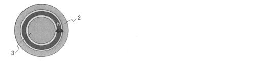
- the friction coefficient ( ⁇ ) of the gap narrowing material can be measured as follows using the narrow gap model tester shown in FIG. A polymer chain assembly as a gap narrowing material is applied to the inner peripheral surface of the ring and the outer peripheral surface of the rod, and the rod is inserted inside the ring.
- the inserted rod is positioned in a one-touch contact state where one side of the rod contacts the upper end of the inner peripheral surface of the ring and the other side of the rod contacts the lower end of the inner peripheral surface of the ring. Inject 0.5 mL of liquid. Subsequently, the rod is moved downward by 10 mm in the Z-axis direction at a speed of 1 mm / s. At this time, a sliding resistance is generated between the ring and the rod, and the ring receives a force. The translational force and moment received by the ring are measured with a 6-component dynamometer, and the friction coefficient ⁇ is calculated.
- the friction coefficient measurement method and the friction coefficient calculation method reference can be made to the column of Examples.
- the gap narrowing material preferably has a compression modulus of 1 MPa or more, a friction coefficient ( ⁇ ) of 0.1 or less, and a lubricating film thickness of 10% or more of the gap, preferably 20%. More preferably, it is more preferably 30% or more.
- the gap narrowing material of the present invention can be used by being fixed to the gap side surface of the member forming the gap.
- the member that forms the gap is referred to as a gap forming member, and the surface on the gap side of the member that forms the gap may be referred to as a “gap forming surface”.
- the surface on which the gap narrowing material is fixed may be either one or both of the surfaces facing each other across the gap (gap forming surface), but both are preferable.
- the gap can be effectively narrowed, and when the gap forming member is composed of a pair of members that move relative to each other, the friction coefficient therebetween can be drastically reduced.
- the gap narrowing material of the present invention is preferably used after being swollen with a liquid substance.
- the swelling with the liquid material may be performed before the gap narrowing material is fixed to the member, or after the gap narrowing material is fixed to the member.
- the corresponding description in the [Other components] column can be referred to.
- the method for fixing the gap narrowing material of the present invention to the gap forming member is not particularly limited, and can be performed, for example, as follows.
- the gap narrowing material can be produced, for example, by grafting polymer chains on the surface of a sheet-like substrate.
- the obtained sheet-like gap narrowing material composite can be fixed to the gap forming surface of the gap forming member by a known method such as adhesion or welding.
- the gap narrowing material can be produced, for example, by graft growth of a polymer chain on the surface of a particulate substrate.
- the obtained fine particle gap narrowing material composite can be fixed to the gap forming surface of the gap forming member by a known method such as adhesion or welding.
- the gap narrowing material can be produced, for example, by grafting a polymer chain on the surface of a fibrous base material.
- the obtained gap narrowing material composite can be fixed to the gap forming surface of the gap forming member by a known method such as adhesion or welding.
- the gap narrowing material may be produced by graft-growing a polymer chain on the gap forming surface using the gap forming member as a base material. In this case, since the gap narrowing material is manufactured in a state of being fixed to the gap forming member, it is not necessary to separately perform a step of fixing the gap narrowing material. Therefore, the process can be simplified.
- the gap narrowing material can be produced as an aggregate of bottle brush-like polymers by using a main chain composed of polymer chains as a base material and grafting a polymer chain as a side chain from the main chain.
- the aggregate of the obtained bottle brush-like polymer can be fixed by performing an annealing treatment after adhering to the gap forming surface of the gap forming member as a solution.
- the gap forming surface to which the solution is attached is surface-treated with a solution such as tetraethyl orthosilicate and the surface is coated with silica or the like.
- the bottle brush polymer solution can be attached to the gap forming surface by, for example, immersing the gap forming member in the solution.
- the width of the gap of the gap forming member to which the gap narrowing material of the present invention is applied is not particularly limited, but is preferably 15 ⁇ m or less, more preferably 10 ⁇ m or less, and even more preferably 5 ⁇ m or less.
- the effect of suppressing fluid leakage of the gap narrowing material is based on fixing the gap narrowing material to the gap forming member and using the effective film thickness b of the polymer chain assembly obtained from the amount of fluid leakage in the gap as an index. Can be evaluated.
- the effective film thickness of the polymer chain assembly refers to the effective film thickness b in the following formula (4).
- h represents a radial gap ( ⁇ m)
- Q is a DEME-TFSI formed in the opening of the gap after fixing the polymer chain assembly on the surface of the member forming the gap.
- This represents the leakage amount (mL) of the ionic liquid from the gap when the ionic liquid is placed
- a is a coefficient (mL / ml) determined from the experimental conditions (gap differential pressure, liquid viscosity, gap length, gap outer diameter).
- b represents the effective film thickness of the polymer chain aggregate in the gap.
- the effective film thickness b of the polymer chain assembly can be measured using a narrow gap model tester shown in FIG.
- the effective film thickness b of the polymer chain assembly in the swollen state is preferably 1.5 times or more, more preferably 2 times or more, and more preferably 3 times or more the dry film thickness of the polymer chain assembly. More preferably.
- the ratio of the effective film thickness b of the polymer chain assembly to the radial gap h is preferably 20% or more, and more preferably 50% or more. 80% or more is more preferable.
- the gap narrowing material composite of the present invention has the gap narrowing material of the present invention and a substrate on which the gap narrowing material is fixed.
- the description in the ⁇ Gap narrowing material> column can be referred to, and for the explanation of the base material, the description in the (base material) column in the gap narrowing material. You can refer to it.
- the usage mode of the gap narrowing material composite [use mode of gap narrowing material] in the gap narrowing material
- the description in the column can be referred to.
- the gap narrowing material of the present invention can be applied to gaps of various articles, and in particular, articles having gaps through which fluid can pass, and it is necessary to suppress leakage of fluid from the gaps. Also effective for articles in which one of a pair of members forming a gap moves relative to the other (particularly articles having a reciprocating sliding mechanism with a narrow gap), journal bearings, sealing, pistons, labyrinth seals, etc. Can be applied. Specifically, a gap between a pair of members of a mating member formed by mating a pair of members that fit into each other, particularly a shaft that is fitted into the mating hole and the shaft hole.
- the gap narrowing material of the present invention can be suitably applied to the gap between the joint hole and the shaft of the article having a mechanism in which the shaft reciprocates in the axial direction.
- the gap narrowing material of the present invention When the gap narrowing material of the present invention is applied to these articles, the gap can be narrowed to effectively suppress the leakage of fluid from the gap, and the relative motion can be prevented smoothly. Can contribute to the realization of simple operation.
- Test apparatus used for evaluation In this example, the narrow gap model tester shown in FIG. 1 was used, and the sealing performance and friction characteristics of the gap narrowing material were measured at room temperature of 25 ° C. and humidity of 20 to 40%. An evaluation test was conducted.
- This narrow gap model testing machine includes a ring 2 that is detachably fixed in the middle of a housing 1, a rod 3 that is inserted inside the ring 2, a rod that performs positioning of the rod 3 and reciprocation in the Z-axis direction.
- a moving mechanism 4 and a pressure measuring device 5 are provided.
- a space in the housing 1 is divided into upper and lower portions by a ring 2, and a lower space 1 a below the ring 2 and an upper space 1 b above the ring 2 are formed.
- the lower space 1b is connected to the vacuum vessel of the pressure measuring device 5 by a connecting pipe, and the upper space 1b constitutes a fluid storage space used for evaluating the sealing performance.
- the narrow gap between the inner circumferential surface of the ring 2 and the outer circumferential surface of the rod 3 corresponds to a gap for arranging the gap narrowing material.
- the width of the gap (the length in the radial direction) is referred to as “radial gap h”.
- the rod and ring conditions used in this example are shown below.
- rods with different outer diameters in the range of 9.92 to 9.99 mm are prepared, and the width of the gap between the ring and the rod (radius gap h) is changed by changing the outer diameter of the rod to be inserted. Adjustment was made within the range of 5 to 40 ⁇ m.
- Equation (1) is a calculation formula for the amount of fluid leakage derived by assuming that the volume change in the vacuum vessel due to fluid leakage is an isothermal change.
- V 0 Initial volume of air in the vacuum container
- P 0 Initial pressure in the vacuum container
- P Pressure change amount after opening the valve (pressure change amount due to liquid leaking)
- ⁇ t Elapsed time from when the valve is opened to when the pressure change is measured
- Formula (2) is a formula for calculating the friction coefficient ⁇ that is derived on the assumption that static balance is established for the ring. The operation for measuring the friction coefficient ⁇ was performed after a running-in operation in which the rod was reciprocated 100 times.
- F z, F x translational force is measured by a dynamometer M y: Moment Z 1 measured by the dynamometer: Distance from the point of force of the ring upper end to a dynamometer Z 2: point of action of the force of the ring lower end Distance from dynamometer
- Gap Narrowing Material 1 Production of Gap Narrowing Material 1 First, an ATRP solution for polymerizing methyl methacrylate (MMA) by an atom transfer radical polymerization method, Polymer, 49, 2008 , 2426-2429. A rod (each rod having a different outer diameter) and a ring serving as a base material were prepared, and surface-initiated living radical polymerization was performed on the surfaces thereof at 60 ° C. and 500 MPa using the above ATRP solution.
- MMA methyl methacrylate
- methyl methacrylate (29.0 g, 4.7 mol / L), Cu (I) Br (0.132 g, 0.015 mol / L), Cu (II) Br 2 (0.0279 g, 0.0020 mol / L), 4,
- 4'-dinonyl-2,2'-bipyridine (0.937g, 0.038mol / L) and anisole (30.00g)
- (2-bromoisobutoxy) propyltrimethoxy A steel rod, steel ring, and silicon wafer with silane immobilized on the surface were placed.
- the vessel was sealed and covered with an aluminum bag, placed in a high-pressure reactor, and a polymerization reaction was carried out at 400 MPa and 60 ° C. for 16 hours.
- the CPB grafted steel sample was washed several times with tetrahydrofuran using a shaker. Then, the rod and ring to which the polymer brush layer as the gap narrowing material 1 was fixed were obtained by drying.
- the sample was taken out from the reaction solution, and the molecular weight and the dry film thickness (graft amount) of the polymer brush layer were analyzed by gel permeation chromatography (elution solvent: tetrahydrofuran) and ellipsometry.
- the molecular weight of the graft chain was evaluated using a free graft membrane obtained by treating a graft membrane formed on a silicon wafer with 10% hydrofluoric acid.
- the polymer brush layer formed on each surface of the rod and ring has a dry film thickness of 1.8 ⁇ m, a number average molecular weight (Mn) of 4 million, a molecular weight distribution index (PDI) of 1.53, and a polymer chain.
- Mn number average molecular weight
- PDI molecular weight distribution index
- a polymer chain was 0.34 chain / nm 2 and the surface occupancy of the polymer chain was 19%.
- a polymer brush layer having a dry film thickness of 1,900 nm was formed on the silicon wafer in the same manner as described above, and was swollen with the ionic liquid DEME-TFSI.
- the equilibrium swollen film thickness was 6,400 nm and the indentation amount was 440 nm. If a cantilever with a larger spring constant is used, its compressive modulus is expected to exceed 1 MPa.
- the test is a combination of a rod formed with the gap narrowing material 1 and a ring formed with the gap narrowing material 1 (rod [gap narrowing material 1] / ring [gap narrowing material 1]), gap narrowing.
- Combination of rod formed with material 1 and ring not formed with gap narrowing material 1 (rod [gap narrowing material 1] / ring [steel]), rod not formed with gap narrowing material 1 and gap narrowing A combination of a ring in which the chemicalizing material 1 is formed (rod [steel] / ring [gap narrowing material 1]), or a ring in which the gap narrowing material 1 is not formed and a ring in which the gap narrowing material 1 is not formed.
- FIG. 3 shows the results of plotting the DEME-TFSI leakage amount Q against the radial gap h for each combination
- FIG. 4 shows the results of plotting the friction coefficient ⁇ against the radial gap h.
- the effective film thickness of the polymer brush was determined from FIG.
- the effective film thickness is the film thickness of the polymer brush obtained based on the leakage amount Q, and corresponds to the radius substantially filled with the polymer brush in the radius gap h. The larger the effective film thickness, the higher the sealing performance (the action of preventing fluid leakage).
- the effective film thickness of the polymer brush can be obtained by graphing a relational expression between the effective radial gap (hb) and the leakage amount Q represented by the following formula (4) and comparing the graph with the measurement result. That is, assuming that the liquid leakage in the gap of the narrow gap model testing machine is a laminar and viscous fluid flow in the concentric annular gap, the relationship between the leakage amount Q and the radial gap h is expressed by the following equation (3).
- the effective film thickness of the polymer brush in the rod [gap narrowing material 1] / ring [gap narrowing material 1] is 7.0 ⁇ m, and the rod [gap narrowing material 1] / ring [steel]) and the rod [
- the effective film thickness of the polymer brush in “steel” / ring [gap narrowing material 1] was 3.5 ⁇ m, and an effective film thickness more than twice that of the dry film thickness of 1.4 ⁇ m could be obtained. From the above, by using a gap narrowing material made of a polymer brush, it is possible to efficiently fill the gaps in the composite member by swelling the solid content (if at least, thereby reducing the gap narrowing material.
- the friction coefficient ⁇ is about 0.2 in the case of rod [steel] / ring [steel] regardless of the radial gap h.
- the gap narrowing material 1] / ring [gap narrowing material 1] it was about 0.003. Therefore, the gap narrowing material including the polymer brush has an excellent friction coefficient reducing action (lubricating effect) in addition to the gap narrowing action, and the friction coefficient reducing action is not dependent on the radial gap h.
- the friction coefficient ⁇ in the case of rod [gap narrowing material 1] / ring [steel] and the friction coefficient ⁇ in the case of rod [steel] / ring [gap narrowing material 1] are respectively the radial gap h.
- the gap narrowing material including the polymer brush exerted a sufficient friction coefficient reducing action even when applied to only one member of the composite member.
- the leak amount Q and the friction coefficient ⁇ in the case of rod [steel] / ring [steel] are both plotted in the upper right region in the figure, and the friction coefficient is high, and sealing It can be seen that the performance is low.
- the rod [gap narrowing material 1] / ring [gap narrowing material 1] especially the radial gap h is 15 ⁇ m, and both high sealing performance and low friction coefficient are compatible. From this, it was found that the width of the gap to which the gap narrowing material is applied is preferably 15 ⁇ m or less.
- Example 2 Production of gap narrowing material 2
- a methacrylate polymer having a living radical polymerization initiating group in the side chain, poly (2- (2-bromo-2-methylpropanoyloxy) ethyl methacrylate) is used as a macroinitiator. It was.
- the macro initiator had a main chain polymerization degree of 200 in terms of polymethyl methacrylate.
- a bottle brush in which methyl methacrylate (hereinafter abbreviated as MMA) and 3-methacryloxypropyltriethoxysilane (hereinafter abbreviated as MOPES) were introduced into the side chain was synthesized by living radical polymerization using the above macroinitiator.
- MMA methyl methacrylate
- MOPES 3-methacryloxypropyltriethoxysilane
- the conversion calculated from the rate of change in weight when heated until no change in weight at 180 ° C. for 90 seconds was determined to be 52.6%. Further, when the molecular weight was measured by GPC using THF solvent (apparatus name: GPC-1011 manufactured by Shodex, column: KF-606L, two coupled, eluent: THF, flow rate: 1.0 mL / min), polymethyl was measured. In terms of methacrylate, Mn was 281900 and PDI was 1.77. A polymer was precipitated with methanol, and purification by reprecipitation recovery was repeated to obtain a bottle brush 1 (hereinafter referred to as BB-1) having a polymethyl methacrylate chain in the side chain.
- BB-1 bottle brush 1
- the number average degree of polymerization of side chains is calculated as 33 from the conversion rate. It was.
- BB-1 was added under a nitrogen gas atmosphere and dissolved with stirring at room temperature.
- the number average degree of polymerization of the side chain was calculated to be 20.
- the surface occupation ratio of the graft side chain was calculated to be 5%.
- the rods (each rod having a different outer diameter) were ultrasonically cleaned and subjected to ultraviolet irradiation for 10 minutes under vacuum, and then ammonia (0.24 mol / L) and tetraethyl orthosilicate (0.03 mol / L). It was immersed in an ethanol solution and allowed to react overnight. The rod subjected to this treatment was immersed in a propylene glycol monomethyl ether acetate solution of a bottle brush (10% by weight), pulled up at 500 ⁇ m / second, allowed to stand and dried, and further under reduced pressure at 120 ° C. An annealing treatment was performed overnight. Through the above steps, the gap narrowing material 2 made of a bottle brush film was formed on the surface of the rod. When the film thickness of this bottle brush was measured using ellipsometry, it was 1442 nm.
- FIG. 9 shows the result of plotting the MEMP-TFSI leakage amount Q against the radial gap h for each combination.
- a curve obtained by graphing b in Formula (4) as 0 ⁇ m, 2 ⁇ m, 4 ⁇ m, and 6 ⁇ m is shown by a solid line.
- the test result of the leakage amount Q of (rod [gap narrowing material 2] / ring [steel]) is generally placed on a curve in which b in formula (4) is set to 2 ⁇ m, and this gap narrowing material.
- the gap narrowing material of the present invention fluid leakage through the gap can be effectively suppressed, and when one member forming the gap moves relative to the other member. In addition, it can contribute to the realization of smooth operation without hindering the movement. Therefore, the gap narrowing material of the present invention is an article having a gap through which a fluid can pass, and it is necessary to suppress the leakage of fluid from the gap, or a pair forming the gap. It can be effectively used as a sealing material disposed in the gap in an article in which these members reciprocate. Therefore, the gap narrowing material of the present invention has high industrial applicability.
Landscapes
- Chemical & Material Sciences (AREA)
- Engineering & Computer Science (AREA)
- Organic Chemistry (AREA)
- Chemical Kinetics & Catalysis (AREA)
- Materials Engineering (AREA)
- Health & Medical Sciences (AREA)
- Medicinal Chemistry (AREA)
- Polymers & Plastics (AREA)
- General Engineering & Computer Science (AREA)
- Inorganic Chemistry (AREA)
- Mechanical Engineering (AREA)
- General Chemical & Material Sciences (AREA)
- Oil, Petroleum & Natural Gas (AREA)
- Addition Polymer Or Copolymer, Post-Treatments, Or Chemical Modifications (AREA)
- Lubricants (AREA)
- Polymerisation Methods In General (AREA)
Abstract
La présente invention concerne un matériau de rétrécissement d'espace libre contenant un agrégat de chaînes polymères en forme de brosse constitué de multiples chaînes polymères immobilisées sur un substrat. L'invention concerne un matériau de rétrécissement d'espace libre qui supprime efficacement des fuites de fluide à travers l'espace libre, sans obstruer le mouvement relatif des éléments qui forment l'espace libre. Ce matériau permet d'obtenir un article dans lequel des éléments qui forment l'espace libre peuvent fonctionner sans à-coups, tout en supprimant les fuites de fluide à travers l'espace libre.
Priority Applications (2)
| Application Number | Priority Date | Filing Date | Title |
|---|---|---|---|
| US16/607,825 US11168170B2 (en) | 2017-04-25 | 2018-04-25 | Clearance narrowing material, clearance narrowing material composite, and article using same |
| JP2019514586A JP7246597B2 (ja) | 2017-04-25 | 2018-04-25 | 隙間狭小化材、隙間狭小化材複合体およびそれらを用いた物品 |
Applications Claiming Priority (2)
| Application Number | Priority Date | Filing Date | Title |
|---|---|---|---|
| JP2017086599 | 2017-04-25 | ||
| JP2017-086599 | 2017-04-25 |
Publications (1)
| Publication Number | Publication Date |
|---|---|
| WO2018199181A1 true WO2018199181A1 (fr) | 2018-11-01 |
Family
ID=63918436
Family Applications (1)
| Application Number | Title | Priority Date | Filing Date |
|---|---|---|---|
| PCT/JP2018/016855 WO2018199181A1 (fr) | 2017-04-25 | 2018-04-25 | Matériau de rétrécissement d'espace libre, composite de matériau de rétrécissement d'espace libre et article l'utilisant |
Country Status (3)
| Country | Link |
|---|---|
| US (1) | US11168170B2 (fr) |
| JP (1) | JP7246597B2 (fr) |
| WO (1) | WO2018199181A1 (fr) |
Cited By (5)
| Publication number | Priority date | Publication date | Assignee | Title |
|---|---|---|---|---|
| JP2019065284A (ja) * | 2017-09-29 | 2019-04-25 | 独立行政法人国立高等専門学校機構 | Srt材料、複合体およびその製造方法 |
| JP2020105460A (ja) * | 2018-12-28 | 2020-07-09 | 日清紡ホールディングス株式会社 | 複合材料 |
| JP2020178109A (ja) * | 2019-04-23 | 2020-10-29 | 新日本無線株式会社 | 圧電素子 |
| WO2021065621A1 (fr) * | 2019-09-30 | 2021-04-08 | 日清紡ホールディングス株式会社 | Matériau composite |
| WO2021200696A1 (fr) | 2020-03-31 | 2021-10-07 | Nok株式会社 | Structure d'étanchéité |
Citations (6)
| Publication number | Priority date | Publication date | Assignee | Title |
|---|---|---|---|---|
| JP2006316169A (ja) * | 2005-05-12 | 2006-11-24 | Chisso Corp | 固形潤滑材 |
| JP2008267572A (ja) * | 2007-04-24 | 2008-11-06 | Idemitsu Kosan Co Ltd | シール装置およびシール方法 |
| JP2014169787A (ja) * | 2013-02-07 | 2014-09-18 | Institute Of National Colleges Of Technology Japan | 摺動機構および摺動部材 |
| JP2014210129A (ja) * | 2013-04-22 | 2014-11-13 | 西島メディカル株式会社 | 人工関節摩擦摩耗試験機、人工関節摩擦摩耗試験機の制御方法 |
| WO2016042912A1 (fr) * | 2014-09-18 | 2016-03-24 | 住友ゴム工業株式会社 | Procédé de modification de surface et corps élastique modifié en surface |
| WO2017171071A1 (fr) * | 2016-03-31 | 2017-10-05 | 国立大学法人京都大学 | Lubrifiant et matériau srt |
Family Cites Families (5)
| Publication number | Priority date | Publication date | Assignee | Title |
|---|---|---|---|---|
| JP3422463B2 (ja) | 1998-03-16 | 2003-06-30 | 科学技術振興事業団 | グラフト表面固体とその製造方法 |
| US6692914B1 (en) * | 1999-07-02 | 2004-02-17 | Symyx Technologies, Inc. | Polymer brushes for immobilizing molecules to a surface or substrate, where the polymers have water-soluble or water-dispersible segments and probes bonded thereto |
| CH708539B1 (en) * | 2012-07-10 | 2017-03-31 | Swatch Group Res & Dev Ltd | Agent for the surface lubrication of an object. |
| JP2016210956A (ja) | 2015-05-11 | 2016-12-15 | 国立研究開発法人物質・材料研究機構 | 生体適合性材料、及び生体適合性コーティング剤 |
| JP7059510B2 (ja) * | 2015-05-26 | 2022-04-26 | エルジー ディスプレイ カンパニー リミテッド | 透明誘電性フィルム、静電容量式タッチパネル及びフレキシブルディスプレイ |
-
2018
- 2018-04-25 WO PCT/JP2018/016855 patent/WO2018199181A1/fr active Application Filing
- 2018-04-25 US US16/607,825 patent/US11168170B2/en active Active
- 2018-04-25 JP JP2019514586A patent/JP7246597B2/ja active Active
Patent Citations (6)
| Publication number | Priority date | Publication date | Assignee | Title |
|---|---|---|---|---|
| JP2006316169A (ja) * | 2005-05-12 | 2006-11-24 | Chisso Corp | 固形潤滑材 |
| JP2008267572A (ja) * | 2007-04-24 | 2008-11-06 | Idemitsu Kosan Co Ltd | シール装置およびシール方法 |
| JP2014169787A (ja) * | 2013-02-07 | 2014-09-18 | Institute Of National Colleges Of Technology Japan | 摺動機構および摺動部材 |
| JP2014210129A (ja) * | 2013-04-22 | 2014-11-13 | 西島メディカル株式会社 | 人工関節摩擦摩耗試験機、人工関節摩擦摩耗試験機の制御方法 |
| WO2016042912A1 (fr) * | 2014-09-18 | 2016-03-24 | 住友ゴム工業株式会社 | Procédé de modification de surface et corps élastique modifié en surface |
| WO2017171071A1 (fr) * | 2016-03-31 | 2017-10-05 | 国立大学法人京都大学 | Lubrifiant et matériau srt |
Cited By (7)
| Publication number | Priority date | Publication date | Assignee | Title |
|---|---|---|---|---|
| JP2019065284A (ja) * | 2017-09-29 | 2019-04-25 | 独立行政法人国立高等専門学校機構 | Srt材料、複合体およびその製造方法 |
| JP2020105460A (ja) * | 2018-12-28 | 2020-07-09 | 日清紡ホールディングス株式会社 | 複合材料 |
| JP7232045B2 (ja) | 2018-12-28 | 2023-03-02 | 日清紡ホールディングス株式会社 | 複合材料 |
| JP2020178109A (ja) * | 2019-04-23 | 2020-10-29 | 新日本無線株式会社 | 圧電素子 |
| WO2021065621A1 (fr) * | 2019-09-30 | 2021-04-08 | 日清紡ホールディングス株式会社 | Matériau composite |
| US11739284B2 (en) | 2019-09-30 | 2023-08-29 | Nisshinbo Holdings Inc. | Composite material |
| WO2021200696A1 (fr) | 2020-03-31 | 2021-10-07 | Nok株式会社 | Structure d'étanchéité |
Also Published As
| Publication number | Publication date |
|---|---|
| US20200181309A1 (en) | 2020-06-11 |
| JPWO2018199181A1 (ja) | 2020-05-14 |
| US11168170B2 (en) | 2021-11-09 |
| JP7246597B2 (ja) | 2023-03-28 |
Similar Documents
| Publication | Publication Date | Title |
|---|---|---|
| JP7246597B2 (ja) | 隙間狭小化材、隙間狭小化材複合体およびそれらを用いた物品 | |
| JP7002080B2 (ja) | 潤滑材及びsrt材料 | |
| JP2006316169A (ja) | 固形潤滑材 | |
| Sakata et al. | Tribological properties of poly (methyl methacrylate) brushes prepared by surface-initiated atom transfer radical polymerization | |
| Xiao et al. | Kinetics of surface-initiated atom transfer radical polymerization of acrylamide on silica | |
| US10882962B2 (en) | SRT material, composite and method for producing the same | |
| WO2000056795A1 (fr) | Procedes catalytiques de polymerisation controlee de monomeres (co)polymerisables par des radicaux libres et systemes de polymeres fonctionnels prepares de la sorte | |
| WO2021117538A1 (fr) | Matériau et système coulissant | |
| Kobayashi et al. | Tribological properties of cross-linked oleophilic polymer brushes on diamond-like carbon films | |
| JP6977964B2 (ja) | 圧縮機及び冷凍サイクル装置 | |
| WO2021117537A1 (fr) | Élément pour prévenir la formation de buée, éliminer l'adhérence des gouttelettes d'eau, éliminer la formation de givre ou éliminer la formation de noyaux glacigènes | |
| JP7435978B2 (ja) | 熱交換器及び冷凍サイクル装置 | |
| US20200056701A1 (en) | Seal Member | |
| JP7333239B2 (ja) | 複合材料 | |
| JP7190693B2 (ja) | 圧縮機及び冷凍サイクル装置 | |
| Okubo et al. | Super-low friction of thermal-treatment-concentrated polymer brushes (TT-CPBs) under boundary lubrication: A practical method to shorten the swelling time of CPBs in solvents | |
| WO2024053649A1 (fr) | Élément pour supprimer la formation de noyau de glace ou supprimer l'accrétion de neige/glace | |
| Tadokoro et al. | Concentrated polymer brush in reciprocating seal improves sealing performance with low friction even for rough surfaces and immiscible fluids | |
| JP7232045B2 (ja) | 複合材料 | |
| Zhang et al. | The electrostatic self‐assembly of microgels on polymer brushes and its effects on interfacial friction | |
| WO2021221057A1 (fr) | Compresseur et dispositif à cycle de réfrigération | |
| JP2021162144A (ja) | 密封装置 | |
| JP2022157406A (ja) | ウイルス不活化構造 |
Legal Events
| Date | Code | Title | Description |
|---|---|---|---|
| 121 | Ep: the epo has been informed by wipo that ep was designated in this application |
Ref document number: 18790536 Country of ref document: EP Kind code of ref document: A1 |
|
| DPE2 | Request for preliminary examination filed before expiration of 19th month from priority date (pct application filed from 20040101) | ||
| ENP | Entry into the national phase |
Ref document number: 2019514586 Country of ref document: JP Kind code of ref document: A |
|
| NENP | Non-entry into the national phase |
Ref country code: DE |
|
| 122 | Ep: pct application non-entry in european phase |
Ref document number: 18790536 Country of ref document: EP Kind code of ref document: A1 |