WO2018198687A1 - 複合材成形治具、複合材成形方法及び複合材 - Google Patents
複合材成形治具、複合材成形方法及び複合材 Download PDFInfo
- Publication number
- WO2018198687A1 WO2018198687A1 PCT/JP2018/014173 JP2018014173W WO2018198687A1 WO 2018198687 A1 WO2018198687 A1 WO 2018198687A1 JP 2018014173 W JP2018014173 W JP 2018014173W WO 2018198687 A1 WO2018198687 A1 WO 2018198687A1
- Authority
- WO
- WIPO (PCT)
- Prior art keywords
- mold
- composite material
- molds
- fibers
- forming
- Prior art date
Links
Images


Classifications
-
- B—PERFORMING OPERATIONS; TRANSPORTING
- B29—WORKING OF PLASTICS; WORKING OF SUBSTANCES IN A PLASTIC STATE IN GENERAL
- B29C—SHAPING OR JOINING OF PLASTICS; SHAPING OF MATERIAL IN A PLASTIC STATE, NOT OTHERWISE PROVIDED FOR; AFTER-TREATMENT OF THE SHAPED PRODUCTS, e.g. REPAIRING
- B29C33/00—Moulds or cores; Details thereof or accessories therefor
- B29C33/20—Opening, closing or clamping
- B29C33/26—Opening, closing or clamping by pivotal movement
-
- B—PERFORMING OPERATIONS; TRANSPORTING
- B29—WORKING OF PLASTICS; WORKING OF SUBSTANCES IN A PLASTIC STATE IN GENERAL
- B29C—SHAPING OR JOINING OF PLASTICS; SHAPING OF MATERIAL IN A PLASTIC STATE, NOT OTHERWISE PROVIDED FOR; AFTER-TREATMENT OF THE SHAPED PRODUCTS, e.g. REPAIRING
- B29C33/00—Moulds or cores; Details thereof or accessories therefor
- B29C33/44—Moulds or cores; Details thereof or accessories therefor with means for, or specially constructed to facilitate, the removal of articles, e.g. of undercut articles
- B29C33/48—Moulds or cores; Details thereof or accessories therefor with means for, or specially constructed to facilitate, the removal of articles, e.g. of undercut articles with means for collapsing or disassembling
-
- B—PERFORMING OPERATIONS; TRANSPORTING
- B29—WORKING OF PLASTICS; WORKING OF SUBSTANCES IN A PLASTIC STATE IN GENERAL
- B29C—SHAPING OR JOINING OF PLASTICS; SHAPING OF MATERIAL IN A PLASTIC STATE, NOT OTHERWISE PROVIDED FOR; AFTER-TREATMENT OF THE SHAPED PRODUCTS, e.g. REPAIRING
- B29C43/00—Compression moulding, i.e. applying external pressure to flow the moulding material; Apparatus therefor
- B29C43/02—Compression moulding, i.e. applying external pressure to flow the moulding material; Apparatus therefor of articles of definite length, i.e. discrete articles
- B29C43/04—Compression moulding, i.e. applying external pressure to flow the moulding material; Apparatus therefor of articles of definite length, i.e. discrete articles using movable moulds
-
- B—PERFORMING OPERATIONS; TRANSPORTING
- B29—WORKING OF PLASTICS; WORKING OF SUBSTANCES IN A PLASTIC STATE IN GENERAL
- B29C—SHAPING OR JOINING OF PLASTICS; SHAPING OF MATERIAL IN A PLASTIC STATE, NOT OTHERWISE PROVIDED FOR; AFTER-TREATMENT OF THE SHAPED PRODUCTS, e.g. REPAIRING
- B29C43/00—Compression moulding, i.e. applying external pressure to flow the moulding material; Apparatus therefor
- B29C43/02—Compression moulding, i.e. applying external pressure to flow the moulding material; Apparatus therefor of articles of definite length, i.e. discrete articles
- B29C43/10—Isostatic pressing, i.e. using non-rigid pressure-exerting members against rigid parts or dies
- B29C43/12—Isostatic pressing, i.e. using non-rigid pressure-exerting members against rigid parts or dies using bags surrounding the moulding material or using membranes contacting the moulding material
-
- B—PERFORMING OPERATIONS; TRANSPORTING
- B29—WORKING OF PLASTICS; WORKING OF SUBSTANCES IN A PLASTIC STATE IN GENERAL
- B29C—SHAPING OR JOINING OF PLASTICS; SHAPING OF MATERIAL IN A PLASTIC STATE, NOT OTHERWISE PROVIDED FOR; AFTER-TREATMENT OF THE SHAPED PRODUCTS, e.g. REPAIRING
- B29C43/00—Compression moulding, i.e. applying external pressure to flow the moulding material; Apparatus therefor
- B29C43/32—Component parts, details or accessories; Auxiliary operations
- B29C43/34—Feeding the material to the mould or the compression means
-
- B—PERFORMING OPERATIONS; TRANSPORTING
- B29—WORKING OF PLASTICS; WORKING OF SUBSTANCES IN A PLASTIC STATE IN GENERAL
- B29C—SHAPING OR JOINING OF PLASTICS; SHAPING OF MATERIAL IN A PLASTIC STATE, NOT OTHERWISE PROVIDED FOR; AFTER-TREATMENT OF THE SHAPED PRODUCTS, e.g. REPAIRING
- B29C43/00—Compression moulding, i.e. applying external pressure to flow the moulding material; Apparatus therefor
- B29C43/32—Component parts, details or accessories; Auxiliary operations
- B29C43/36—Moulds for making articles of definite length, i.e. discrete articles
- B29C43/3607—Moulds for making articles of definite length, i.e. discrete articles with sealing means or the like
-
- B—PERFORMING OPERATIONS; TRANSPORTING
- B29—WORKING OF PLASTICS; WORKING OF SUBSTANCES IN A PLASTIC STATE IN GENERAL
- B29C—SHAPING OR JOINING OF PLASTICS; SHAPING OF MATERIAL IN A PLASTIC STATE, NOT OTHERWISE PROVIDED FOR; AFTER-TREATMENT OF THE SHAPED PRODUCTS, e.g. REPAIRING
- B29C43/00—Compression moulding, i.e. applying external pressure to flow the moulding material; Apparatus therefor
- B29C43/32—Component parts, details or accessories; Auxiliary operations
- B29C43/36—Moulds for making articles of definite length, i.e. discrete articles
- B29C43/42—Moulds for making articles of definite length, i.e. discrete articles for undercut articles
-
- B—PERFORMING OPERATIONS; TRANSPORTING
- B29—WORKING OF PLASTICS; WORKING OF SUBSTANCES IN A PLASTIC STATE IN GENERAL
- B29C—SHAPING OR JOINING OF PLASTICS; SHAPING OF MATERIAL IN A PLASTIC STATE, NOT OTHERWISE PROVIDED FOR; AFTER-TREATMENT OF THE SHAPED PRODUCTS, e.g. REPAIRING
- B29C53/00—Shaping by bending, folding, twisting, straightening or flattening; Apparatus therefor
- B29C53/02—Bending or folding
- B29C53/04—Bending or folding of plates or sheets
-
- B—PERFORMING OPERATIONS; TRANSPORTING
- B29—WORKING OF PLASTICS; WORKING OF SUBSTANCES IN A PLASTIC STATE IN GENERAL
- B29C—SHAPING OR JOINING OF PLASTICS; SHAPING OF MATERIAL IN A PLASTIC STATE, NOT OTHERWISE PROVIDED FOR; AFTER-TREATMENT OF THE SHAPED PRODUCTS, e.g. REPAIRING
- B29C70/00—Shaping composites, i.e. plastics material comprising reinforcements, fillers or preformed parts, e.g. inserts
- B29C70/04—Shaping composites, i.e. plastics material comprising reinforcements, fillers or preformed parts, e.g. inserts comprising reinforcements only, e.g. self-reinforcing plastics
- B29C70/28—Shaping operations therefor
- B29C70/40—Shaping or impregnating by compression not applied
- B29C70/42—Shaping or impregnating by compression not applied for producing articles of definite length, i.e. discrete articles
- B29C70/44—Shaping or impregnating by compression not applied for producing articles of definite length, i.e. discrete articles using isostatic pressure, e.g. pressure difference-moulding, vacuum bag-moulding, autoclave-moulding or expanding rubber-moulding
- B29C70/446—Moulding structures having an axis of symmetry or at least one channel, e.g. tubular structures, frames
-
- B—PERFORMING OPERATIONS; TRANSPORTING
- B29—WORKING OF PLASTICS; WORKING OF SUBSTANCES IN A PLASTIC STATE IN GENERAL
- B29C—SHAPING OR JOINING OF PLASTICS; SHAPING OF MATERIAL IN A PLASTIC STATE, NOT OTHERWISE PROVIDED FOR; AFTER-TREATMENT OF THE SHAPED PRODUCTS, e.g. REPAIRING
- B29C70/00—Shaping composites, i.e. plastics material comprising reinforcements, fillers or preformed parts, e.g. inserts
- B29C70/04—Shaping composites, i.e. plastics material comprising reinforcements, fillers or preformed parts, e.g. inserts comprising reinforcements only, e.g. self-reinforcing plastics
- B29C70/28—Shaping operations therefor
- B29C70/40—Shaping or impregnating by compression not applied
- B29C70/42—Shaping or impregnating by compression not applied for producing articles of definite length, i.e. discrete articles
- B29C70/46—Shaping or impregnating by compression not applied for producing articles of definite length, i.e. discrete articles using matched moulds, e.g. for deforming sheet moulding compounds [SMC] or prepregs
- B29C70/461—Rigid movable compressing mould parts acting independently from opening or closing action of the main mould
-
- B—PERFORMING OPERATIONS; TRANSPORTING
- B29—WORKING OF PLASTICS; WORKING OF SUBSTANCES IN A PLASTIC STATE IN GENERAL
- B29C—SHAPING OR JOINING OF PLASTICS; SHAPING OF MATERIAL IN A PLASTIC STATE, NOT OTHERWISE PROVIDED FOR; AFTER-TREATMENT OF THE SHAPED PRODUCTS, e.g. REPAIRING
- B29C43/00—Compression moulding, i.e. applying external pressure to flow the moulding material; Apparatus therefor
- B29C43/02—Compression moulding, i.e. applying external pressure to flow the moulding material; Apparatus therefor of articles of definite length, i.e. discrete articles
- B29C43/04—Compression moulding, i.e. applying external pressure to flow the moulding material; Apparatus therefor of articles of definite length, i.e. discrete articles using movable moulds
- B29C2043/043—Compression moulding, i.e. applying external pressure to flow the moulding material; Apparatus therefor of articles of definite length, i.e. discrete articles using movable moulds rotating on their own axis without linear displacement
Definitions
- Embodiments of the present invention relate to a composite material forming jig, a composite material forming method, and a composite material.
- GFRP glass fiber reinforced plastic
- CFRP carbon fiber reinforced plastic
- a composite material having a shape that is difficult to release from the mold cannot be integrally molded using the mold.
- a composite material having a complicated shape must be divided into a plurality of parts and then assembled by fasteners after being heated and cured, or a laminated body of prepregs laminated for each part must be assembled and integrally cured (cocure). I don't get it.
- a method for producing a composite material having a complicated shape there is also known a method in which a pre-cured part is set on a prepreg before curing, and adhesive curing (co-bonding) is performed simultaneously with the prepreg curing. .
- a composite structure in which a reinforcing material such as a girder (spar), a small bone (rib), or a stringer (stringer) is attached to an outer panel (panel), which is typical as one of aircraft structures.
- a reinforcing material such as a girder (spar), a small bone (rib), or a stringer (stringer) is attached to an outer panel (panel), which is typical as one of aircraft structures.
- a reinforcing material such as a girder (spar), a small bone (rib), or a stringer (stringer) is attached to an outer panel (panel), which is typical as one of aircraft structures.
- the assembly work is performed by the fasteners.
- the laminate of the prepreg for the outer plate and the laminate of the prepreg for the reinforcing material are separately manufactured, and the laminate is assembled and then heat-cured.
- an object of the present invention is to make it possible to easily form a composite material having a complicated structure.
- a composite material forming jig according to an embodiment of the present invention is a plurality of forming dies capable of unfolding and tilting at least one forming die relative to other forming dies, , Laminating at least one of a plurality of sheet-like fibers impregnated with a resin and a plurality of sheet-like fibers before impregnating the resin, and relatively tilting the at least one mold and It has a plurality of molds for shaping the fiber and an inclination mechanism.
- the tilt mechanism expands the plurality of molds when performing the stacking, and tilts the at least one mold when performing the shaping.
- the composite material molding method includes a step of setting a plurality of molding dies that are capable of inclining at least one molding die relative to other molding dies in an unfolded state. Laminating at least one of a plurality of sheet-like fibers impregnated with resin and a plurality of sheet-like fibers before impregnating the resin with the plurality of molds in the unfolded state; and A step of shaping the fibers after lamination impregnated with the resin by relatively inclining a mold, and heat-curing the fibers after shaping impregnated with the resin under pressure A step of producing a composite product or semi-finished product in which the resin after curing is reinforced with the fiber.
- the composite material according to the embodiment of the present invention has a shape in which a laminate of fiber reinforced resin layers in which a resin after curing is reinforced with fibers is bent in the same direction at at least four locations.
- FIG. 2 is a top view of the composite material forming jig shown in FIG. 1.
- FIG. 4 is a top view of the composite material forming jig shown in FIG. 3.
- the perspective view which shows the structural example of the outer plate
- deployed the box structure shown in FIG. The figure explaining the method of forming a groove
- molding die by the moving mechanism shown in FIG. The flowchart which shows an example of the flow which shape
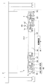
- FIG. 1 is a front view showing a configuration of a composite material forming jig according to a first embodiment of the present invention in an unfolded state
- FIG. 2 is a top view of the composite material forming jig shown in FIG. 1
- FIG. 4 is a top view of the composite material forming jig shown in FIG. 3.
- the composite material forming jig 1 is a jig for laminating a prepreg before curing by impregnating a sheet-like fiber bundle with a thermosetting resin, shaping the laminated prepreg, and heating and curing the prepreg laminate. It is.
- thermosetting resin instead of the sheet-like prepreg, sheet-like fibers are laminated using the composite material forming jig 1.
- a fiber reinforced resin layer (PLY) made of prepreg is laminated on the composite material forming jig 1.
- a fiber reinforced resin layer laminate made of prepreg or laminated.
- a laminated body of fiber reinforced resin layers obtained by impregnating the cured fibers with a thermosetting resin is shaped by the composite material forming jig 1.
- the sheet-like prepreg or the sheet-like fiber is not shown.
- the molding method of the composite material in which the resin is impregnated after the fibers are laminated is called an RTM (Resin Transfer Molding) method.
- RTM Resin Transfer Molding
- VaRTM Vauum Assisted Resin Transfer Molding
- the composite material forming jig 1 can be used for prepreg lamination and composite material forming by the hybrid forming method using the RTM method together.
- the hybrid molding method is a molding method of a composite material in which sheet-like fibers are laminated on a prepreg laminate, the laminated sheet-like fibers are impregnated with a resin, and then heat-cured. Therefore, when the composite material forming jig 1 is used for forming a composite material by the hybrid forming method, both the sheet-like prepreg and the sheet-like fiber are laminated.
- any method can be adopted as a method of heat-curing the composite material.
- a typical heat curing method for the composite material there is a method in which the composite material before curing is carried into an autoclave molding apparatus, vacuumed, and heat cured under pressure.
- various deautoclave (OoA: Autoclaving) molding methods for molding a composite material without using an autoclave molding apparatus are known.
- a method of heat-curing a composite material in an oven is known. Accordingly, the composite material forming jig 1 in which the composite material before curing and after shaping is set can be carried into a desired facility corresponding to the heat curing method of the composite material.
- the composite material forming jig 1 can change the structure between the unfolded state and the assembled state as illustrated in FIGS.
- the composite material forming jig 1 is set in an unfolded state as shown in FIGS.
- the composite material forming jig 1 is set in an assembled state as shown in FIGS. 3 and 4 at the time of shaping and heat curing of the fiber impregnated with the resin.
- a plurality of sheet-like fibers obtained by impregnating a resin in the unfolded composite material forming jig 1 either automatically with the automatic laminating apparatus 2 or manually without using the automatic laminating apparatus 2 That is, at least one of a plurality of sheet-like fibers before impregnation with the prepreg sheet and the resin can be laminated.
- the composite material forming jig 1 is folded and assembled to cure the fiber reinforced resin layer laminate composed of fibers impregnated with the resin before curing. It can be shaped according to the shape of the composite material later.
- the composite material forming jig 1 includes at least a plurality of forming dies 3 and an inclination mechanism 4.
- the plurality of molds 3 can be unfolded by the tilt mechanism 4 and at least one mold 3 can be tilted relative to the other molds 3.
- the tilt mechanism 4 has a structure capable of tilting at least one mold 3.
- Each mold 3 is a jig for laminating at least one of a plurality of sheet-like fibers impregnated with a resin and a plurality of sheet-like fibers before impregnating the resin in an unfolded state. Accordingly, each mold 3 has a plane for laminating prepregs or fibers or a curved surface with a small curvature. In other words, the laminated surface formed on the surface of each mold 3 is not limited to a flat surface but may be a curved surface as long as there is no problem in the lamination of prepregs or fibers.
- Each mold 3 can be composed of a composite material such as CFRP or a rigid body such as metal.
- the structure of each mold 3 can be a desired structure such as a plate shape, a block shape, or a hollow box structure.
- the respective molds 3 are arranged such that when the respective molds 3 are unfolded, the stacked surfaces of the respective molds 3 are substantially flat. For this reason, not only can the operator manually laminate sheet-like prepregs or fibers on each lamination surface of the plurality of molds 3 in the unfolded state, but also traveling such as wheels and crawlers as shown in the figure. Sheet-like prepregs or fibers can be automatically laminated using the automatic laminating apparatus 2 provided with a mechanism. Or you may make it laminate
- At least one of the plurality of molds 3 can be inclined relative to the other molds 3.
- stacking can be performed.
- it can heat-harden in the state which set the laminated body of the shaped fiber reinforced resin layer to the some shaping
- a composite material having a shape after shaping can be produced.
- the tilting mechanism 4 develops a plurality of molds 3 when laminating prepregs or fibers, while tilting at least one mold 3 when shaping a laminate of fiber reinforced resin layers. Instrument or device.
- the tilt mechanism 4 can be constituted by a hinge 4A having no power, for example, as shown in the figure.
- a hinge 4A having no power for example, as shown in the figure.
- at least one mold 3 to be tilted and the mold 3 adjacent to the mold 3 to be tilted can be rotatably connected by a plurality of hinges 4A.
- the tilting mechanism 4 can be a raising / lowering device for the mold 3 having power.
- an automatic raising / lowering device for the mold 3 can be configured by providing a motor for rotating the hinge 4 ⁇ / b> A that connects the molds 3.
- a plurality of hinges 4A for connecting the common molds 3 may be connected by a rotating shaft.
- the tilt mechanism 4 can be provided with a structure for regulating the tilt angle. That is, the inclination angle of the mold 3 to be inclined is changed only between the inclination angle with respect to the adjacent mold 3 in the unfolded state and the inclination angle with respect to the adjacent mold 3 in the assembled state.
- a stopper structure for limiting the tilt angle can be provided in the tilt mechanism 4 so as to be able to do so.
- FIG. 5 is a diagram showing an example in which a stopper structure having an inclination angle is provided on the hinge 4A used as the inclination mechanism 4 of the mold 3 to be tilted
- FIG. 6 is for tilting the mold 3 to be tilted. It is a figure in the state which moved hinge 4A shown in FIG.
- the tilt angle of the mold 3 to be tilted is 0 degree with respect to the adjacent mold 3 while the mold 3 is tilted when the mold 3 is assembled.
- the hinge 4A is capable of rotating one member relative to the other member in the range of 0 to 90 degrees.
- the tilting mechanism 4 can be configured using
- the rotation range of the hinge 4A can be limited to 0 degree to 90 degrees.
- a hinge 4 ⁇ / b> A in which two plate-like components 10, 11 are arranged so that the thickness direction is a rotation axis direction and are connected by a rotation shaft 12.
- the rotation range of the plate-like component 10 on the rotating side is limited to a range of 0 to 90 degrees by contacting the plate-like component 10 on the rotating side.
- the stopper 13 can be provided on the other plate-like component 11. Thereby, the shaping
- the molding die 3 is tilted at a plurality of different tilt angles to thereby provide a plurality of different assembled states.
- a plurality of molds 3 may be arranged. In that case, it is possible to mold composite materials having different shapes by using a plurality of common molds 3.
- a plurality of types of stringers having different flange inclination angles with respect to the web can be manufactured using a plurality of common molds 3.
- the composite material forming jig 1 is composed of two forming dies 3 having a substantially flat surface and at least one of the two forming dies 3 can be inclined relative to the other by the inclination mechanism 4,
- a composite material having a L-shaped cross section in which a laminate of fiber reinforced resin layers after curing is bent at one place can be formed.
- the composite material forming jig 1 is provided with three or more plural molds 3, and at least two of the plural molds 3 are relative to other molds 3 by the tilt mechanism 4. If it can be made to incline, the female shaping jig
- the composite material produced by the composite material forming jig 1 becomes a composite material without joints having a shape obtained by bending a laminated body of fiber reinforced resin layers after curing.
- the resin after curing is a fiber. It is possible to manufacture a composite material having a shape in which a laminate of fiber reinforced resin layers reinforced in 1 is bent in the same direction at at least three locations.
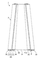
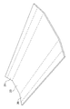
- FIG. 7 is a perspective view showing an example of the structure of the outer plate and the girder constituting the aircraft wing structure.
- the aircraft wing structure has a structure in which front and rear girders are provided on the outer plate. For this reason, conventionally, there are many cases in which the outer plate, the front girder and the rear girder are respectively manufactured and assembled by fasteners or the like. Alternatively, a laminated body of prepregs for outer plates, a laminated body of prepregs for front girders, and a laminated body of prepregs for rear girders are manufactured, and a wing structure is manufactured by integrally curing in a combined state. There is also a case.
- the composite material forming jig 1 illustrated in FIGS. 1 to 4 when used, the cross section in which the front beam 20 and the rear beam 21 are formed at both ends of the outer plate 23 as shown in FIG. A C-shaped box structure 24 can be manufactured.
- a typical box structure 24 constituting the main wing and the tail wing is a long structure that narrows toward the wing tip. Therefore, the composite material forming jig 1 is used not only for a long structure having a constant cross-sectional shape but also for a long structure whose cross-section changes like the box structure 24 shown in FIG. Can be produced.
- FIG. 8 is a perspective view showing a state where the box structure 24 shown in FIG. 7 is developed.
- the box structure 24 shown in FIG. 7 has a structure that can be developed in a planar manner although the cross section is not constant. That is, when the front beam 20 and the rear beam 21 are developed, the box structure 24 becomes a planar component. Therefore, a plurality of molds 3 are arranged in an unfolded state in accordance with the shape of the unfolded box structure 24, and a sheet-like prepreg or fiber is placed on the plurality of molds 3 in the unfolded state. It can be laminated by work.
- the box structure 24 shown in FIG. 7 has a structure in which a laminate of fiber reinforced resin layers is bent in the same direction at four locations. That is, the front girder 20 and the rear girder 21 are each a plate-like composite material bent at one place, and the front girder 20 and the rear girder 21 themselves are formed by being bent from a plate-like outer plate 23, respectively.
- the composite material forming jig 1 includes four molds 3A, 3B, 3C, and 3D for the front beam 20 and the rear beam 21 and 1 for the outer plate 23 as illustrated in FIGS.
- One mold 3E can be used.
- the four forming dies 3A, 3B, 3C, 3D for the front spar 20 and the rear spar 21 are developed to roughly form the respective forming dies 3A, 3B, 3C, 3D, 3E. It can be arranged flat.
- the shape of the outer plate 23 constituting the box structure 24 is not a rectangle, but is generally a trapezoid. For this reason, the shape of the surface of the mold 3E for the outer plate 23 is also substantially trapezoidal. Accordingly, the top view of the entire developed molds 3A, 3B, 3C, 3D, and 3E is not necessarily rectangular. That is, the shape of the surface of each mold 3 is determined according to the shape of the composite material before deployment. For this reason, if the shape of the outer plate 23 is rectangular, the shape of the surface of the molding die 3E for the outer plate 23 is also rectangular.
- the four molding dies 3A, 3B, 3C, and 3D for the front spar 20 and the rear spar 21 are respectively arranged on the inner side with respect to the adjacent molding dies 3.
- the mold 3B for use can be inclined approximately 90 degrees with respect to the mold 3E for the outer plate 23.
- the molding die 3C for the rear beam 21 on the end side is inclined by approximately 90 degrees with respect to the molding die 3D for the rear beam 21 on the outer plate 23 side, and the molding for the rear beam 21 on the outer plate 23 side.
- the mold 3D can be inclined by approximately 90 degrees with respect to the mold 3E for the outer plate 23.
- chamfering such as R chamfering or C chamfering is often performed. Therefore, as shown in FIGS. 3 and 4, the four molding dies 3A, 3B, 3C, and 3D for the front beam 20 and the rear beam 21 are inclined inward with respect to the adjacent molding tools 3, respectively.
- a chamfering mold 30 can be assembled in each gap between the molds 3A, 3B, 3C, 3D, and 3E.
- R chamfering molds 30 are arranged on the crest side of the laminated body of fiber reinforced resin layers bent at four locations, respectively. That is, the gap formed between the mold 3A for the front beam 20 on the end side and the mold 3B for the front beam 20 on the outer plate 23 side, the mold for the front beam 20 on the outer plate 23 side. 3B and the gap formed between the molding die 3E for the outer plate 23, the molding die 3C for the rear beam 21 on the end side, and the molding die 3D for the rear beam 21 on the outer plate 23 side.
- the chamfering mold 30 for R chamfering are disposed in the gap formed between the molding die 3D for the rear beam 21 and the molding die 3E for the outer plate 23 on the outer plate 23 side. Yes.
- the chamfering mold 30 can be connected to the adjacent mold 3 with bolts or the like.
- the tilt mechanism 4 when arranging the chamfering mold 30, it is necessary to prevent the chamfering mold 30 and the tilt mechanism 4 such as the hinge 4 ⁇ / b> A from interfering with each other. Therefore, as shown in the figure, when the tilt mechanism 4 is configured by a hinge 4A in which two plate-like parts 10 and 11 are arranged so that the thickness direction is substantially the rotation axis direction and connected by the rotation shaft 12.
- the tilting mechanism 4 can be provided at a position that does not interfere with the chamfering mold 30.
- the hinge 4A can be attached to the side surfaces of the two adjacent molds 3 without being attached to the gap between the two adjacent molds 3 to be installed with the chamfering mold 30. Accordingly, it is possible to install the chamfering mold 30 between the two adjacent molds 3 in a state where the two adjacent molds 3 are rotatably connected by the hinge 4A.
- a flat hinge is a hinge in which the edges of two plate-like parts are connected by a rotating shaft, and the length direction of the rotating shaft is substantially perpendicular to the thickness direction of the two plate-like parts. It is.
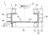
- the laminated body of prepregs set in the molding dies 3A, 3B, 3C, 3D, and 3E after assembly is bagged with vacuuming before heat curing.
- bagging with vacuuming is performed to impregnate the resin into the sheet-like fibers laminated on the assembled molds 3A, 3B, 3C, 3D, and 3E. Is called. That is, in the case of the VaRTM method, bagging is performed prior to resin impregnation.
- Bagging is performed by covering the prepreg or fiber laminate with the bagging film 31, attaching the end of the bagging film 31 to the surfaces of the molds 3A, 3B, 3C, 3D, and 3E with the sealant 32, and then using the bagging film 31. This can be done by depressurizing the covered area with the vacuum pump 33.
- a chamfering mold 30 and a chamfering mold 30 are provided by providing a groove in at least one of the molds 3A, 3B, 3C, 3D, and 3E and inserting a rubber packing 34A in the groove. 30 and each mold 3A, 3B, 3C, 3D, 3E can be sealed.
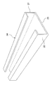
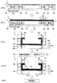
- FIG. 9 is a view for explaining a method of forming the groove 30A in the R chamfering mold 30 shown in FIG. 3 and sealing with the packing 34A.
- the illustration of the hinge 4A is omitted.
- the structure of the R chamfering mold 30 can be a hollow box structure having a curved surface 30B and two planes 30C sandwiching the curved surface 30B as surfaces.
- the curved surface 30B of the mold 30 for R chamfering is a surface for shaping the shape of the R chamfer.
- the two flat surfaces 30C sandwiching the curved surface 30B are surfaces for contacting and fixing the end surfaces of the two molds 3.
- a groove 30A for inserting the rubber packing 34A can be formed.
- the groove 30A is formed on the surface to be sealed of the mold 30 for R chamfering. Accordingly, the grooves 30A are formed on the two flat surfaces 30C of the R-chamfering mold 30 that contacts the end surfaces of the two molds 3.
- the packing 34A inserted into the groove 30A formed in the mold 30 for R chamfering into a ring shape In order to reduce the inflow of air into the bagging area, it is important to make the packing 34A inserted into the groove 30A formed in the mold 30 for R chamfering into a ring shape. That is, it is important not to form an end portion on the packing 34A. Therefore, as illustrated in FIG. 9A, the end of the groove 30A formed in the two flat surfaces 30C of the R chamfering mold 30 is used for R chamfering so that the ring-shaped packing 34A can be inserted.
- the curved surfaces 30B can be opposed to each other.
- the gap formed between the two molds 3 is used for R chamfering.
- the mold 30 can be installed.
- the curved surface 30B for R chamfering is shaped by the two molds 3 as shown in FIG. It will be exposed between the faces. Therefore, a part of the packing 34A along the curved surface 30B for R chamfering is exposed to the bagging film 31 side.
- the exposed portion of the packing 34A is sealed together with the end portion of the bagging film 31, as shown in FIG. It is preferable to seal with tape 35.
- region covered with the bagging film 31 can be made low, and the differential pressure
- the pressure difference between the pressure in the region covered with the bagging film 31 and the atmospheric pressure is applied to the sheet-like fiber laminate before impregnating the resin. Can be loaded.
- the bagging target is a prepreg laminate
- the prepreg itself since the prepreg itself has adhesive strength, it will not loosen or fall even if the prepreg laminate is placed below the mold 3 after assembly. .
- the bagging target is a laminated body of sheet-like fibers before impregnating the resin
- the fibers arranged below the mold 3 after assembly are loosened by the action of gravity before bagging. It is necessary to prevent falling. Therefore, when the bagging target is a laminated body of sheet-like fibers before impregnating the resin, it is appropriate to fix with a binder. Thereby, the laminated body of fibers can be attached to the mold 3. That is, it is possible to prevent the end portion of the fiber from dropping due to gravity before bagging.
- the target mold 3 is tilted by the tilt mechanism 4 such as the hinge 4A, so that the fiber-reinforced resin layer without wrinkles A laminated body can be shaped easily.
- the composite material forming jig 1 can be provided with a moving mechanism 40 that changes the gaps between the plurality of forming dies 3 in the unfolded state and a control device 41 of the moving mechanism 40.
- each mold 3A, 3B, 3C, 3D, 3E in the unfolded state is on the lower surface side so that the moving mechanism 40 can be attached to each mold 3A, 3B, 3C, 3D, 3E. It has a hollow box structure that is open without being closed.
- a ball screw 40A is used as the moving mechanism 40 for adjusting the gaps between the molds 3A, 3B, 3C, 3D, and 3E. That is, two adjacent molds 3 are connected by the ball screw 40A.
- the motor 40B is fixed inside one of the two adjacent molds 3.
- the output shaft of the motor 40B is integrated with a ball screw 40A penetrating both the two molds 3.
- a nut 40 ⁇ / b> C that is fastened to the ball screw 40 ⁇ / b> A is fixed inside the other of the two adjacent molds 3.
- the ball screw 40 ⁇ / b> A is arranged such that the length direction is the adjustment direction of the gap between the molds 3.
- molds 3A, 3B, 3C, and 3D for the front beam 20 and the rear beam 21 are placed on a traveling mechanism 42 such as a carriage having wheels.
- the mold 3E for the outer plate 23 is placed on a base 43 having no traveling function. Therefore, the molds 3A, 3B, 3C, and 3D for the front and rear girders 20 and 21 can be translated relative to the mold 3E for the outer plate 23 by rotational driving of each ball screw 40A.
- the two molds 3A and 3B for the front beam 20 and the mold 3E for the outer plate 23 are connected with a common ball screw and the ball screw is rotated, the two molds 3A for the front beam 20 are 3B may be translated relative to the molding die 3E for the outer plate 23 by the same distance.
- the two molding dies 3C and 3D for the rear girder 21 and the molding die 3E for the outer plate 23 are connected with a common ball screw and the ball screw is rotated, the two molding dies 3C for the rear girder 21 are obtained.
- 3D may be moved in parallel relative to the mold 3E for the outer plate 23 by the same distance.
- FIG. 10 is a diagram for explaining a method for adjusting the gap between the molds 3A, 3B, 3C, 3D, and 3E by the moving mechanism 40 shown in FIG.
- the gap between the molds 3 When the gap between the molds 3 can be adjusted by the moving mechanism 40 such as the ball screw 40A, the gap between the molds 3 is set at the time of assembling the mold 3 at the start of lamination of the sheet-like prepreg or the sheet-like fibers. It can be made longer than the gap. And as the number of prepregs or fibers laminated increases so that the length of the mountain side becomes longer than the length of the prepreg after lamination or the valley side of the fiber that is bent by inclining the mold 3 to be inclined. The gaps between the plurality of molds 3 can be gradually narrowed by driving the moving mechanism 40.
- the gap between the forming dies 3 can be adjusted to the length of the chamfered chamfer side.
- molding die 3 can be narrowed as the number of lamination
- FIG. 10 (D) the gap between the forming dies 3 is adjusted to the length on the valley side of the R chamfer.
- the thickness of the prepreg or fiber laminate is shown to be thicker than the actual thickness.
- the length of the prepreg or the fiber at the lowermost portion laminated on the mold 3 side becomes the length of the chamfered crest between the molds 3, and the most mold
- the length of the prepreg or fiber in the uppermost part laminated on the side away from 3 is the length of the valley side of the R chamfer between the molds 3. Therefore, when the prepreg or the fiber laminate is bent by inclining the mold 3, it can be formed into an R chamfered shape without generating wrinkles.
- a composite structure having a shape in which a plate is bent like a box structure 24 in which front and rear girders 20 and 21 are formed at both ends of an outer plate 23 as illustrated in FIG. It can be integrally molded with R chamfering at a high quality.
- the mold 3 is tilted by the tilt mechanism 4 with the gap between the molds 3 being the narrowest. Therefore, depending on the structure of the tilting mechanism 4 such as the hinge 4A, it is necessary to be detachable with a bolt or the like to the molding die 3 to be tilted and the molding die 3 adjacent to the molding die 3 to be tilted. For this reason, as shown in FIG. 10D, the hinge 4A is attached to the mold 3 with a bolt or the like after the last prepreg or fiber is laminated.
- the moving mechanism 40 such as the ball screw 40A needs to be detachable from the molding die 3 so that each molding die 3 after the adjustment of the gap can be tilted and assembled. For this reason, in the example shown in FIGS. 3 and 4, the moving mechanism 40 including the ball screw 40 ⁇ / b> A is removed from each mold 3.
- the moving mechanism 40 of the molding die 3 is not limited to the ball screw 40A, but may be configured by a linear movement mechanism such as a rack and pinion, a hydraulic cylinder or an air cylinder, or a traveling mechanism such as a crawler having power. it can.
- a linear movement mechanism such as a rack and pinion, a hydraulic cylinder or an air cylinder, or a traveling mechanism such as a crawler having power. It can.
- the positioning accuracy of the mold 3 affects the quality of the composite material. For this reason, it is preferable to configure the moving mechanism 40 for adjusting the gap between the forming dies 3 using a ball screw 40A with good positioning accuracy from the viewpoint of forming a composite material with good quality.
- the control device 41 is a device that controls the moving mechanism 40 so that the gap between the molds 3 becomes narrower as the number of laminated fibers before impregnating the resin, that is, the prepreg or the fiber before impregnating the resin, increases. In order to control the gap between the molds 3 more accurately, it is necessary to specify the number of laminated prepregs or fibers. For this reason, the control device 41 obtains information indicating the number of prepregs or fibers laminated from the automatic lamination device 2 that automatically laminates the prepregs or fibers on the mold 3, and determines the obtained number of prepregs or fibers laminated. The moving mechanism 40 can be controlled based on the information shown.
- information indicating the number of laminated prepregs or fibers can be acquired from the automatic laminating apparatus 2 as a potential signal in the control apparatus 41. Then, the relationship between the number of prepregs or fibers laminated and the length of the gap between the molds 3 is preset in the control device 41, and the appropriate gap between the molds 3 corresponding to the number of prepregs or fibers laminated is determined appropriately. The length can be specified. Then, a control signal can be output from the control device 41 to the moving mechanism 40 so that a gap having a specified length is formed between the molds 3.
- a control signal for controlling the amount of rotation is output from the control device 41 to the motor 40B as an electric signal.
- the moving mechanism 40 is configured by a non-electric device such as an air cylinder or a hydraulic cylinder, a control signal is output to the moving mechanism 40 as an air signal or the like according to the configuration of the moving mechanism 40.
- control device 41 can be configured by an electric circuit such as a computer loaded with a program. Further, in order to configure the control device 41, a signal circuit such as an air signal circuit or a hydraulic signal circuit that converts an electrical signal into an air signal or a hydraulic signal and outputs it to the moving mechanism 40 can be used as necessary. .
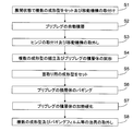
- FIG. 11 is a flowchart showing an example of a flow of forming a composite material using the composite material forming jig 1 shown in FIG.
- step S1 a plurality of molds 3 capable of inclining at least one mold 3 relative to other molds 3 are set in an unfolded state.
- FIG. 10 (A) in a state where the four molds 3A, 3B, 3C, 3D for the front beam 20 and the rear beam 21 and the mold 3E for the outer plate 23 are deployed. Arranged in the lamination area of the automatic lamination apparatus 2. At this time, the hinge 4A as the tilt mechanism 4 is removed from the respective molds 3A, 3B, 3C, 3D, and 3E.
- a moving mechanism 40 including a ball screw 40A is attached between the respective molds 3A, 3B, 3C, 3D, and 3E.
- the initial position of the relative position between the ball screw 40A and the nut 40C is a position where the gap between the molds 3A, 3B, 3C, 3D, and 3E is the length of the chamfered chamfer side.
- step S2 automatic prepreg lamination is performed. That is, the prepreg is stacked on the respective molds 3A, 3B, 3C, 3D, and 3E in the developed state by the automatic stacking apparatus 2.
- the moving mechanism 40 is driven so that the gaps between the molding dies 3A, 3B, 3C, 3D, and 3E are gradually narrowed as the number of prepreg laminations increases.
- the control device 41 acquires information indicating the number of prepregs stacked from the automatic stacking device 2. Based on the acquired information, the control device 41 has a length on the mountain side longer than a length on the valley side of the prepreg after being stacked by inclining each mold 3A, 3B, 3C, 3D. In this manner, as shown in FIGS. 10B and 10C, the moving mechanism 40 is controlled so that the gaps between the molding dies 3A, 3B, 3C, 3D, and 3E become narrower as the number of stacked prepregs increases.
- control value of the rotation amount of the motor 40B corresponding to the control value of the gap between the molds 3A, 3B, 3C, 3D, and 3E is output from the control device 41 to the motor 40B as a control signal.
- the motor 40B rotates, and the ball screw 40A has a length corresponding to the control value of the rotation amount of the motor 40B.
- the gap between the molds 3A, 3B, 3C, 3D, and 3E becomes a gap corresponding to the control value.
- the length of the prepreg in the lowermost part stacked on the most molding die 3A, 3B, 3C, 3D, 3E side is the length of the chamfered crest between the molding dies 3A, 3B, 3C, 3D, 3E.
- the length of the prepreg at the uppermost portion laminated on the side farthest from the molds 3A, 3B, 3C, 3D, and 3E is the length of the chamfered valley side between the molds 3A, 3B, 3C, 3D, and 3E. It becomes.
- the hinge 4A is attached and the moving mechanism 40 is removed in step S3.
- the hinge 4A and the moving mechanism 40 can be attached to and detached from the molds 3A, 3B, 3C, 3D, and 3E with bolts or the like.
- step S4 the prepreg laminate is shaped by assembling the molds 3A, 3B, 3C, 3D, and 3E. That is, the operator can lift the forming dies 3A, 3B, 3C, and 3D to be tilted by a crane such as an electric hoist or a forklift, and can tilt the rotating shaft 12 of the hinge 4A as a fulcrum. Alternatively, the molding dies 3A, 3B, 3C, and 3D to be tilted may be tilted using a dedicated tilting device.
- the female mold having a concave surface for shaping the prepreg laminate is formed.
- a shaping jig is formed.
- a female shaping jig having a concave surface for shaping the laminate of prepregs can be formed.
- the prepreg laminate is shaped according to the shape of the female shaping jig.
- step S5 a chamfering mold 30 is set. That is, the chamfering mold 30 is disposed in a gap formed between the mold 3 in an inclined state and the mold 3 adjacent to the mold 3 in an inclined state. Thereby, it is possible to perform shaping for forming chamfers in the prepreg laminate.
- Each chamfering mold 30 is set in a state in which the gap between the chamfering mold 30 and the mold 3 adjacent to the chamfering mold 30 is sealed by the seal member 34.
- the gap between the chamfering mold 30 and the molds 3A, 3B, 3C, 3D, and 3E is sealed with a packing 34A.
- step S6 bagging of the prepreg laminate is performed. Therefore, the prepreg laminate is covered with the bagging film 31.
- the end of the bagging film 31 is sealed with a sealant 32 to each mold 3A, 3B, 3C, 3D, 3E.
- the area covered with the bagging film 31 is connected to the vacuum pump 33 by a vacuum hose. Thereafter, the vacuum pump 33 is operated, and the region surrounded by the bagging film 31 covering the prepreg laminate and the respective molds 3A, 3B, 3C, 3D, and 3E is brought into a vacuum state.
- step S7 the prepreg laminate is heat-cured under pressure. That is, the laminated body of prepregs that has been shaped and bagged using the assembled molds 3A, 3B, 3C, 3D, and 3E is carried into a heating facility such as an autoclave molding apparatus or an oven. And the laminated body of the prepreg pressurized by the vacuum pressure is heated with heating equipment. As a result, a thermosetting resin is cured, and a composite product or semi-finished product in which the cured resin is reinforced with fibers can be manufactured.
- step S8 jigs such as the molding dies 3A, 3B, 3C, 3D, 3E and the bagging film 31 are removed. That is, the molding dies 3A, 3B, 3C, 3D, and 3E after assembly on which the composite product or semi-finished product after heat curing is placed are carried out of the heating facility.
- the molds 3A, 3B, 3C, and 3D can be lifted by a crane or a forklift, and can be deployed with the rotating shaft 12 of the hinge 4A as a fulcrum.
- the molds 3A, 3B, 3C, and 3D may be developed using a dedicated tilting device.
- other jigs such as the bagging film 31 are removed from the composite product or semi-finished product.
- the composite product or semi-finished product is produced using a female shaping jig having a shaping concave surface formed by bending the molding die 3, the resin after curing is reinforced with fibers. It becomes a composite product or semi-finished product having a shape in which the laminate of fiber reinforced resin layers is bent in at least two places. As shown in the figure, if the four shaping dies 3A, 3B, 3C, and 3D are bent to form a female shaping jig, a part of the upper surface and both sides as illustrated in FIG. The box structure 24 having a shape that is opened and the laminated body of the fiber reinforced resin layers is bent at four positions can be manufactured.
- FIG. 12 is a diagram showing an example of a flow in the case of forming a composite material by a hybrid forming method using the composite material forming jig 1 shown in FIG.
- step S10 When molding a composite material by the hybrid molding method, in step S10, a predetermined number of prepregs are stacked on each of the molding dies 3A, 3B, 3C, 3D, and 3E in the unfolded state.
- the moving mechanism 40 is driven so that the gaps between the molding dies 3A, 3B, 3C, 3D, and 3E gradually become narrower as the number of prepreg laminations increases.
- step S11 a plurality of sheet-like fibers before being impregnated with the resin are laminated on the prepreg laminate, which is a plurality of sheet-like fibers impregnated with the resin.
- Sheet-like fibers can also be automatically laminated in the same manner as the prepreg. Of course, at least one of the prepreg and the sheet-like fiber may be laminated manually.
- the moving mechanism 40 is driven so that the gaps between the molds 3A, 3B, 3C, 3D, and 3E gradually narrow as the number of laminated fibers increases.
- the moving mechanism 40 is removed and the hinge 4A is attached.
- step S12 the molds 3A, 3B, 3C, 3D, and 3E are assembled and the mold 30 for chamfering is assembled.
- the molds 3A, 3B, 3C, 3D, and 3E are assembled, one of the laminates placed on the mold 3A for the front beam 20 on the end side and the mold 3C for the rear beam 21 on the end side The portions are on the lower surface side of the mold 3A and the mold 3C, respectively.
- the prepreg adheres due to the adhesive strength of the resin layer before curing. Accordingly, the prepreg laminate is not peeled off by its own weight from the mold 3A for the front beam 20 on the end side and the mold 3C for the rear beam 21 on the end side.
- the sheet-like fibers before impregnating the resin have no adhesive force. Therefore, the end portions of the sheet-like fibers are fixed by a binder so that the end portions of the sheet-like fibers are not peeled off from the forming die 3A for the front beam 20 on the end side and the forming die 3C for the rear beam 21 on the end side. Thereby, the edge part of a sheet-like fiber can be affixed on the shaping
- the chamfering mold 30 is assembled. That is, the chamfering molds 30 are arranged in the four corner spaces formed between the molds 3A, 3B, 3C, 3D, and 3E. Each mold 30 and the adjacent molds 3A, 3B, 3C, 3D, and 3E are sealed with a seal member 34 such as a packing 34A.
- step S13 bagging of the fiber laminate before impregnation with the prepreg and resin and injection of the resin into the fiber laminate are performed. Specifically, a laminated body of prepregs and fibers placed on the assembled molds 3A, 3B, 3C, 3D, and 3E is covered with a bagging film 31 and attached with a sealant 32.
- the area covered with the bagging film 31 is connected to the vacuum pump 33 by a vacuum hose. Further, the region covered with the bagging film 31 is connected to the resin storage container 50 by a supply pipe. Thereafter, the vacuum pump 33 is operated, and the region surrounded by the bagging film 31 covering the prepreg and sheet-like fiber laminate and the respective molds 3A, 3B, 3C, 3D, and 3E is brought into a vacuum state.
- thermosetting resin is injected into the vacuum region in the bagging film 31 pressurized by evacuation from the resin storage container 50 through the supply pipe.
- a sheet-like fiber can be impregnated with resin.
- the sheet-like fibers are impregnated with the resin, a laminate of a plurality of fiber reinforced resin layers in which the fibers are impregnated with the resin before curing is formed in the vacuum region in the bagging film 31.
- the laminated body of the fiber reinforced resin layers is shaped by the vacuum pressure and the assembled molds 3A, 3B, 3C, 3D, and 3E. Further, the four corners of the laminated body of fiber reinforced resin layers are shaped by the chamfering mold 30 into a shape in which chamfering such as R chamfering is performed.
- step S14 the fiber laminate after impregnation with the resin is heat-cured under pressure. That is, heat curing of the laminated body of fiber reinforced resin layers after shaping is performed.
- a composite product or semi-finished product having a shape as illustrated in FIG. 7 in which the cured resin is reinforced with fibers can be produced.
- Semi-finished products can also be manufactured.
- the molds 3A, 3B, and 3C are assembled after the sheet-like fibers are laminated on the molds 3A, 3B, 3C, 3D, and 3E in the unfolded state, and the mold 30 for chamfering is assembled. Bagging and resin injection are performed on sheet-like fibers set in 3D and 3E.
- the product of a composite material or a semi-finished product is manufactured by the heat-hardening of the laminated body of the fiber reinforced resin layer after the shaping manufactured by injection
- a complicated structure such as a box structure 24 having front and rear beams 20 and 21 formed at both ends of the outer plate 23 as illustrated in FIG.
- a composite material having a shape can be integrally formed. That is, by simply laminating sheet-like prepregs or sheet-like fibers, a composite material having a complicated shape can be easily formed without assembling each part. For this reason, if the automatic laminating apparatus 2 is used, the work labor required for molding a composite material having a complicated shape can be drastically reduced.
- the gap between the molds 3 with the moving mechanism 40 such as the ball screw 40A, it is possible to prevent wrinkles from being generated in the prepreg or fiber that is bent due to the inclination of the mold 3. As a result, the quality of the composite material after curing can be maintained even if the prepreg or fiber is deformed after lamination.
- FIG. 13 is a partially enlarged view showing the configuration of the composite material forming jig according to the second embodiment of the present invention.
- the forming dies 3 are connected by a flexible sheet 60 such as silicon.
- a step is provided at the surface end of the mold 3 so that the surfaces of the developed molds 3 are smoothly connected in a state where the sheet 60 is attached. Can do. For this reason, at least one of a sheet-like prepreg and a sheet-like fiber can be laminated on the plurality of molds 3 in the unfolded state.
- FIG. 14 is a diagram showing an example in which the gap formed between the molds 3 shown in FIG. 13 is narrowed.
- the moving mechanism 40 such as a ball screw 40A or the like moves between the molds 3.
- the gap in can be narrowed. That is, according to the shape of the R chamfer of the composite material after molding, the prepreg or fiber closer to the molding die 3 can be loosened more greatly. Thereby, it can prevent that a wrinkle generate
- the hinge 4A can be attached.
- FIG. 15 is a view showing a state where the mold 3 shown in FIG. 14 is assembled.
- the mold 3 can be assembled as shown in FIG. 15 by attaching the hinge 4A. If it does so, the sheet
- the composite material forming jig 1A and the composite material forming method in the second embodiment as described above are obtained when the forming die 3 is inclined by connecting the forming dies 3 with a flexible sheet 60.
- the composite material before curing can be chamfered.
- the composite material forming jig 1A and the composite material forming method in the second embodiment in addition to the effects obtained by the composite material forming jig 1 and the composite material forming method in the first embodiment, for chamfering.
- the effect that the molding die 30 and the sealing member 34 can be eliminated can be obtained. Therefore, the mounting work of the chamfering mold 30 and the seal member 34 is not required, and it becomes possible to manufacture a composite material having a complicated shape with a simpler work.
Landscapes
- Engineering & Computer Science (AREA)
- Mechanical Engineering (AREA)
- Chemical & Material Sciences (AREA)
- Composite Materials (AREA)
- Moulding By Coating Moulds (AREA)
- Moulds For Moulding Plastics Or The Like (AREA)
Priority Applications (5)
| Application Number | Priority Date | Filing Date | Title |
|---|---|---|---|
| CN201880024169.7A CN110520267A (zh) | 2017-04-28 | 2018-04-02 | 复合材料成型夹具、复合材料成型方法和复合材料 |
| JP2019515188A JP6778817B2 (ja) | 2017-04-28 | 2018-04-02 | 複合材成形治具及び複合材成形方法 |
| EP18789888.7A EP3616873B1 (de) | 2017-04-28 | 2018-04-02 | Formwerkzeug für verbundstoff, formverfahren für verbundstoff und verbundstoff |
| ES18789888T ES2954715T3 (es) | 2017-04-28 | 2018-04-02 | Plantilla de conformado de material compuesto, método de conformado de material compuesto y material compuesto |
| US16/665,088 US11584042B2 (en) | 2017-04-28 | 2019-10-28 | Composite material forming jig, composite material forming method and composite material |
Applications Claiming Priority (2)
| Application Number | Priority Date | Filing Date | Title |
|---|---|---|---|
| JP2017-089546 | 2017-04-28 | ||
| JP2017089546 | 2017-04-28 |
Related Child Applications (1)
| Application Number | Title | Priority Date | Filing Date |
|---|---|---|---|
| US16/665,088 Continuation US11584042B2 (en) | 2017-04-28 | 2019-10-28 | Composite material forming jig, composite material forming method and composite material |
Publications (1)
| Publication Number | Publication Date |
|---|---|
| WO2018198687A1 true WO2018198687A1 (ja) | 2018-11-01 |
Family
ID=63919753
Family Applications (1)
| Application Number | Title | Priority Date | Filing Date |
|---|---|---|---|
| PCT/JP2018/014173 WO2018198687A1 (ja) | 2017-04-28 | 2018-04-02 | 複合材成形治具、複合材成形方法及び複合材 |
Country Status (6)
| Country | Link |
|---|---|
| US (1) | US11584042B2 (de) |
| EP (1) | EP3616873B1 (de) |
| JP (1) | JP6778817B2 (de) |
| CN (1) | CN110520267A (de) |
| ES (1) | ES2954715T3 (de) |
| WO (1) | WO2018198687A1 (de) |
Cited By (1)
| Publication number | Priority date | Publication date | Assignee | Title |
|---|---|---|---|---|
| CN109571992A (zh) * | 2018-11-22 | 2019-04-05 | 北京理工大学 | 一种纤维增强复合材料连接件的加工方法 |
Families Citing this family (7)
| Publication number | Priority date | Publication date | Assignee | Title |
|---|---|---|---|---|
| WO2018047869A1 (ja) * | 2016-09-07 | 2018-03-15 | 三菱重工業株式会社 | 複合材の成形方法及び複合材の成形用治具 |
| US11207808B1 (en) * | 2020-06-29 | 2021-12-28 | Thermwood Corporation | Systems and methods for producing parts at elevated temperatures |
| CN112046030A (zh) * | 2020-08-26 | 2020-12-08 | 安庆柯麦机电科技有限公司 | 通讯设备箱体成型系统 |
| CN112046033A (zh) * | 2020-08-26 | 2020-12-08 | 安庆柯麦机电科技有限公司 | 通讯设备箱体成型方法 |
| CN112046034A (zh) * | 2020-08-26 | 2020-12-08 | 安庆柯麦机电科技有限公司 | 通讯设备箱体成型模具 |
| CN113650316B (zh) * | 2021-08-13 | 2022-08-09 | 东华大学 | 一种连续折叠式减振拉胀纺织复合材料的加工装置与方法 |
| CN114438892A (zh) * | 2022-02-11 | 2022-05-06 | 中铁四局集团有限公司 | 一种钢梁组拼用多功能抄垫工装 |
Citations (8)
| Publication number | Priority date | Publication date | Assignee | Title |
|---|---|---|---|---|
| JPS4010719B1 (de) * | 1962-10-22 | 1965-05-29 | ||
| JP2006335049A (ja) | 2005-06-06 | 2006-12-14 | Mitsubishi Heavy Ind Ltd | 複合材シート加工装置、複合構造材の形成方法 |
| WO2007102573A1 (ja) * | 2006-03-08 | 2007-09-13 | Toray Industries, Inc. | 強化繊維成形体の製造方法および製造装置 |
| JP2010115867A (ja) * | 2008-11-13 | 2010-05-27 | Fuji Heavy Ind Ltd | 折曲成形装置 |
| JP2014051065A (ja) | 2012-09-10 | 2014-03-20 | Mitsubishi Heavy Ind Ltd | プリプレグ積層材の成形装置および成形方法 |
| JP2015142993A (ja) * | 2014-01-31 | 2015-08-06 | 三菱重工業株式会社 | Frp成形治具及びfrp構造体の成形方法 |
| JP2015157481A (ja) | 2014-02-18 | 2015-09-03 | ザ・ボーイング・カンパニーTheBoeing Company | 複合充填材 |
| JP2015229304A (ja) * | 2014-06-05 | 2015-12-21 | 富士重工業株式会社 | 成形治具及び成形方法 |
Family Cites Families (8)
| Publication number | Priority date | Publication date | Assignee | Title |
|---|---|---|---|---|
| GB2244453A (en) * | 1990-04-04 | 1991-12-04 | Dowty Aerospace Gloucester | Laying up table |
| WO2013046452A1 (ja) * | 2011-09-30 | 2013-04-04 | 富士重工業株式会社 | 繊維強化樹脂複合材及びその製造方法 |
| US9248613B2 (en) * | 2012-10-30 | 2016-02-02 | The Boeing Company | Method for forming thick thermoplastic composite structures |
| CN105014987A (zh) * | 2014-04-29 | 2015-11-04 | 哈尔滨飞机工业集团有限责任公司 | 一种复合材料共固化盒段结构加强肋r角的成型方法 |
| CN106458131A (zh) * | 2014-06-16 | 2017-02-22 | 沙特基础工业全球技术有限公司 | 制备层压板的方法、吸能装置、吸能装置组合物及成形工具 |
| GB201507414D0 (en) * | 2015-04-30 | 2015-06-17 | Composite Technology & Applic Ltd | A method of Manufacturing a Composite Component |
| JP6914035B2 (ja) * | 2016-12-28 | 2021-08-04 | スリーエム イノベイティブ プロパティズ カンパニー | シート状積層体の製造方法、シート状積層体を成形する金型、及びシート状積層体 |
| JP7450560B2 (ja) | 2021-01-08 | 2024-03-15 | 三菱電機株式会社 | リソース決定装置、リソース決定方法及びリソース決定プログラム |
-
2018
- 2018-04-02 WO PCT/JP2018/014173 patent/WO2018198687A1/ja active Application Filing
- 2018-04-02 ES ES18789888T patent/ES2954715T3/es active Active
- 2018-04-02 CN CN201880024169.7A patent/CN110520267A/zh active Pending
- 2018-04-02 EP EP18789888.7A patent/EP3616873B1/de active Active
- 2018-04-02 JP JP2019515188A patent/JP6778817B2/ja active Active
-
2019
- 2019-10-28 US US16/665,088 patent/US11584042B2/en active Active
Patent Citations (8)
| Publication number | Priority date | Publication date | Assignee | Title |
|---|---|---|---|---|
| JPS4010719B1 (de) * | 1962-10-22 | 1965-05-29 | ||
| JP2006335049A (ja) | 2005-06-06 | 2006-12-14 | Mitsubishi Heavy Ind Ltd | 複合材シート加工装置、複合構造材の形成方法 |
| WO2007102573A1 (ja) * | 2006-03-08 | 2007-09-13 | Toray Industries, Inc. | 強化繊維成形体の製造方法および製造装置 |
| JP2010115867A (ja) * | 2008-11-13 | 2010-05-27 | Fuji Heavy Ind Ltd | 折曲成形装置 |
| JP2014051065A (ja) | 2012-09-10 | 2014-03-20 | Mitsubishi Heavy Ind Ltd | プリプレグ積層材の成形装置および成形方法 |
| JP2015142993A (ja) * | 2014-01-31 | 2015-08-06 | 三菱重工業株式会社 | Frp成形治具及びfrp構造体の成形方法 |
| JP2015157481A (ja) | 2014-02-18 | 2015-09-03 | ザ・ボーイング・カンパニーTheBoeing Company | 複合充填材 |
| JP2015229304A (ja) * | 2014-06-05 | 2015-12-21 | 富士重工業株式会社 | 成形治具及び成形方法 |
Non-Patent Citations (1)
| Title |
|---|
| See also references of EP3616873A4 |
Cited By (1)
| Publication number | Priority date | Publication date | Assignee | Title |
|---|---|---|---|---|
| CN109571992A (zh) * | 2018-11-22 | 2019-04-05 | 北京理工大学 | 一种纤维增强复合材料连接件的加工方法 |
Also Published As
| Publication number | Publication date |
|---|---|
| ES2954715T3 (es) | 2023-11-23 |
| JP6778817B2 (ja) | 2020-11-04 |
| US11584042B2 (en) | 2023-02-21 |
| CN110520267A (zh) | 2019-11-29 |
| JPWO2018198687A1 (ja) | 2020-02-27 |
| EP3616873A1 (de) | 2020-03-04 |
| US20200055266A1 (en) | 2020-02-20 |
| EP3616873B1 (de) | 2023-05-31 |
| EP3616873A4 (de) | 2021-01-20 |
Similar Documents
| Publication | Publication Date | Title |
|---|---|---|
| WO2018198687A1 (ja) | 複合材成形治具、複合材成形方法及び複合材 | |
| CN111452947B (zh) | 成形复合桁条 | |
| US10442153B2 (en) | Stiffened stringer panel with integral indexing laminate stacks | |
| EP3213907B1 (de) | Dynamische formwerkzeuge für verbundteile | |
| JP6774571B2 (ja) | 複合材成形治具及び複合材成形方法 | |
| US10647408B2 (en) | Composite structure with integrated hinge | |
| JP7066430B2 (ja) | 一体化複合構造製造システム | |
| WO2019049411A1 (ja) | プリフォーム賦形装置 | |
| US11873093B2 (en) | Composite plank support for stringer panel | |
| EP3501804A1 (de) | Versteifte längsträgerplatte mit integrierten indexierungslaminatstapeln | |
| JP7156851B2 (ja) | 最小限に加工されたストリンガーの現場製造のためのシステム及び方法 | |
| EP3744627A1 (de) | Stringerlose-sandwich-rumpfplatten | |
| CN110406082A (zh) | 制造用于交通工具的复合桁梁的方法 | |
| JP2003071864A (ja) | 複合材補強板の製造方法 | |
| US9221236B1 (en) | Systems and methods for assembling stiffened composite structures | |
| CN110104202B (zh) | 使用铰接式芯轴的复合飞机制造工具 | |
| US10434687B2 (en) | Composite laminate tooling and method of forming a composite part using the tooling | |
| US6565690B1 (en) | Process for manufacturing structures of composite material | |
| US11981426B2 (en) | Composite spars with integrated sacrificial surfaces |
Legal Events
| Date | Code | Title | Description |
|---|---|---|---|
| 121 | Ep: the epo has been informed by wipo that ep was designated in this application |
Ref document number: 18789888 Country of ref document: EP Kind code of ref document: A1 |
|
| ENP | Entry into the national phase |
Ref document number: 2019515188 Country of ref document: JP Kind code of ref document: A |
|
| NENP | Non-entry into the national phase |
Ref country code: DE |
|
| WWE | Wipo information: entry into national phase |
Ref document number: 2018789888 Country of ref document: EP |
|
| ENP | Entry into the national phase |
Ref document number: 2018789888 Country of ref document: EP Effective date: 20191128 |