WO2018198613A1 - ホログラフィー再生方法及びプログラム - Google Patents
ホログラフィー再生方法及びプログラム Download PDFInfo
- Publication number
- WO2018198613A1 WO2018198613A1 PCT/JP2018/011397 JP2018011397W WO2018198613A1 WO 2018198613 A1 WO2018198613 A1 WO 2018198613A1 JP 2018011397 W JP2018011397 W JP 2018011397W WO 2018198613 A1 WO2018198613 A1 WO 2018198613A1
- Authority
- WO
- WIPO (PCT)
- Prior art keywords
- particle beam
- image
- charged particle
- diffraction
- wave
- Prior art date
- Legal status (The legal status is an assumption and is not a legal conclusion. Google has not performed a legal analysis and makes no representation as to the accuracy of the status listed.)
- Ceased
Links
Images













Classifications
-
- H—ELECTRICITY
- H01—ELECTRIC ELEMENTS
- H01J—ELECTRIC DISCHARGE TUBES OR DISCHARGE LAMPS
- H01J37/00—Discharge tubes with provision for introducing objects or material to be exposed to the discharge, e.g. for the purpose of examination or processing thereof
- H01J37/02—Details
- H01J37/22—Optical, image processing or photographic arrangements associated with the tube
-
- G—PHYSICS
- G03—PHOTOGRAPHY; CINEMATOGRAPHY; ANALOGOUS TECHNIQUES USING WAVES OTHER THAN OPTICAL WAVES; ELECTROGRAPHY; HOLOGRAPHY
- G03H—HOLOGRAPHIC PROCESSES OR APPARATUS
- G03H1/00—Holographic processes or apparatus using light, infrared or ultraviolet waves for obtaining holograms or for obtaining an image from them; Details peculiar thereto
- G03H1/04—Processes or apparatus for producing holograms
- G03H1/0443—Digital holography, i.e. recording holograms with digital recording means
-
- G—PHYSICS
- G03—PHOTOGRAPHY; CINEMATOGRAPHY; ANALOGOUS TECHNIQUES USING WAVES OTHER THAN OPTICAL WAVES; ELECTROGRAPHY; HOLOGRAPHY
- G03H—HOLOGRAPHIC PROCESSES OR APPARATUS
- G03H1/00—Holographic processes or apparatus using light, infrared or ultraviolet waves for obtaining holograms or for obtaining an image from them; Details peculiar thereto
- G03H1/0005—Adaptation of holography to specific applications
-
- G—PHYSICS
- G03—PHOTOGRAPHY; CINEMATOGRAPHY; ANALOGOUS TECHNIQUES USING WAVES OTHER THAN OPTICAL WAVES; ELECTROGRAPHY; HOLOGRAPHY
- G03H—HOLOGRAPHIC PROCESSES OR APPARATUS
- G03H1/00—Holographic processes or apparatus using light, infrared or ultraviolet waves for obtaining holograms or for obtaining an image from them; Details peculiar thereto
- G03H1/04—Processes or apparatus for producing holograms
- G03H1/08—Synthesising holograms, i.e. holograms synthesized from objects or objects from holograms
- G03H1/0866—Digital holographic imaging, i.e. synthesizing holobjects from holograms
-
- G—PHYSICS
- G03—PHOTOGRAPHY; CINEMATOGRAPHY; ANALOGOUS TECHNIQUES USING WAVES OTHER THAN OPTICAL WAVES; ELECTROGRAPHY; HOLOGRAPHY
- G03H—HOLOGRAPHIC PROCESSES OR APPARATUS
- G03H1/00—Holographic processes or apparatus using light, infrared or ultraviolet waves for obtaining holograms or for obtaining an image from them; Details peculiar thereto
- G03H1/04—Processes or apparatus for producing holograms
- G03H1/16—Processes or apparatus for producing holograms using Fourier transform
-
- G—PHYSICS
- G03—PHOTOGRAPHY; CINEMATOGRAPHY; ANALOGOUS TECHNIQUES USING WAVES OTHER THAN OPTICAL WAVES; ELECTROGRAPHY; HOLOGRAPHY
- G03H—HOLOGRAPHIC PROCESSES OR APPARATUS
- G03H5/00—Holographic processes or apparatus using particles or using waves other than those covered by groups G03H1/00 or G03H3/00 for obtaining holograms; Processes or apparatus for obtaining an optical image from them
-
- H—ELECTRICITY
- H01—ELECTRIC ELEMENTS
- H01J—ELECTRIC DISCHARGE TUBES OR DISCHARGE LAMPS
- H01J37/00—Discharge tubes with provision for introducing objects or material to be exposed to the discharge, e.g. for the purpose of examination or processing thereof
- H01J37/02—Details
- H01J37/20—Means for supporting or positioning the object or the material; Means for adjusting diaphragms or lenses associated with the support
-
- H—ELECTRICITY
- H01—ELECTRIC ELEMENTS
- H01J—ELECTRIC DISCHARGE TUBES OR DISCHARGE LAMPS
- H01J37/00—Discharge tubes with provision for introducing objects or material to be exposed to the discharge, e.g. for the purpose of examination or processing thereof
- H01J37/02—Details
- H01J37/22—Optical, image processing or photographic arrangements associated with the tube
- H01J37/222—Image processing arrangements associated with the tube
-
- H—ELECTRICITY
- H01—ELECTRIC ELEMENTS
- H01J—ELECTRIC DISCHARGE TUBES OR DISCHARGE LAMPS
- H01J37/00—Discharge tubes with provision for introducing objects or material to be exposed to the discharge, e.g. for the purpose of examination or processing thereof
- H01J37/26—Electron or ion microscopes; Electron or ion diffraction tubes
- H01J37/295—Electron or ion diffraction tubes
-
- G—PHYSICS
- G03—PHOTOGRAPHY; CINEMATOGRAPHY; ANALOGOUS TECHNIQUES USING WAVES OTHER THAN OPTICAL WAVES; ELECTROGRAPHY; HOLOGRAPHY
- G03H—HOLOGRAPHIC PROCESSES OR APPARATUS
- G03H1/00—Holographic processes or apparatus using light, infrared or ultraviolet waves for obtaining holograms or for obtaining an image from them; Details peculiar thereto
- G03H1/0005—Adaptation of holography to specific applications
- G03H2001/005—Adaptation of holography to specific applications in microscopy, e.g. digital holographic microscope [DHM]
-
- G—PHYSICS
- G03—PHOTOGRAPHY; CINEMATOGRAPHY; ANALOGOUS TECHNIQUES USING WAVES OTHER THAN OPTICAL WAVES; ELECTROGRAPHY; HOLOGRAPHY
- G03H—HOLOGRAPHIC PROCESSES OR APPARATUS
- G03H1/00—Holographic processes or apparatus using light, infrared or ultraviolet waves for obtaining holograms or for obtaining an image from them; Details peculiar thereto
- G03H1/04—Processes or apparatus for producing holograms
- G03H1/0443—Digital holography, i.e. recording holograms with digital recording means
- G03H2001/0452—Digital holography, i.e. recording holograms with digital recording means arranged to record an image of the object
-
- G—PHYSICS
- G03—PHOTOGRAPHY; CINEMATOGRAPHY; ANALOGOUS TECHNIQUES USING WAVES OTHER THAN OPTICAL WAVES; ELECTROGRAPHY; HOLOGRAPHY
- G03H—HOLOGRAPHIC PROCESSES OR APPARATUS
- G03H2222/00—Light sources or light beam properties
- G03H2222/40—Particular irradiation beam not otherwise provided for
- G03H2222/44—Beam irradiating the object at recording stage
-
- G—PHYSICS
- G03—PHOTOGRAPHY; CINEMATOGRAPHY; ANALOGOUS TECHNIQUES USING WAVES OTHER THAN OPTICAL WAVES; ELECTROGRAPHY; HOLOGRAPHY
- G03H—HOLOGRAPHIC PROCESSES OR APPARATUS
- G03H2223/00—Optical components
- G03H2223/23—Diffractive element
-
- H—ELECTRICITY
- H01—ELECTRIC ELEMENTS
- H01J—ELECTRIC DISCHARGE TUBES OR DISCHARGE LAMPS
- H01J2237/00—Discharge tubes exposing object to beam, e.g. for analysis treatment, etching, imaging
- H01J2237/22—Treatment of data
- H01J2237/221—Image processing
- H01J2237/223—Fourier techniques
-
- H—ELECTRICITY
- H01—ELECTRIC ELEMENTS
- H01J—ELECTRIC DISCHARGE TUBES OR DISCHARGE LAMPS
- H01J2237/00—Discharge tubes exposing object to beam, e.g. for analysis treatment, etching, imaging
- H01J2237/22—Treatment of data
- H01J2237/226—Image reconstruction
-
- H—ELECTRICITY
- H01—ELECTRIC ELEMENTS
- H01J—ELECTRIC DISCHARGE TUBES OR DISCHARGE LAMPS
- H01J2237/00—Discharge tubes exposing object to beam, e.g. for analysis treatment, etching, imaging
- H01J2237/22—Treatment of data
- H01J2237/226—Image reconstruction
- H01J2237/228—Charged particle holography
-
- H—ELECTRICITY
- H01—ELECTRIC ELEMENTS
- H01J—ELECTRIC DISCHARGE TUBES OR DISCHARGE LAMPS
- H01J2237/00—Discharge tubes exposing object to beam, e.g. for analysis treatment, etching, imaging
- H01J2237/26—Electron or ion microscopes
- H01J2237/2614—Holography or phase contrast, phase related imaging in general, e.g. phase plates
Definitions
- the present invention relates to a particle beam apparatus using a diffraction effect, and particularly to a reproduction technique effective for holography using a diffraction grating.
- Charged particle beams such as electron beams and ion beams must be propagated in a vacuum, the wavelength is as short as several pm, the deflection angle is small, and there is no effective beam splitter like a half mirror in optics. For this reason, it is difficult to create an optical system independently by creating a plurality of optical paths like a Mach-Zehnder interferometer on an optical bench. In addition, it is difficult to construct an effective optical element because of its good transmittance with electromagnetic waves with short wavelengths such as ultraviolet rays and X-rays, and there is no optical element in the first place with particle beams such as neutron beams, molecular beams, and heavy particle beams. .
- a sample is arranged between the light source and the detector, and only observation of a scattering / absorption image on the sample by path propagation or observation of a diffraction pattern based on interference / diffraction effects is performed. That is, in any of the above electromagnetic wave devices and particle beam devices, a one-path optical system is used, and the same lens and the same deflector are used for the transmitted beam that has passed through the sample and the scattered / diffracted beam. Measurement methods using the same optical conditions must be used.
- Non-Patent Document 1 that discloses a method of creating two irradiation conditions in one lens barrel as a Fourier transform holography using an electron beam and a lens
- Patent document 1 which disclosed the possibility of producing irradiation conditions.
- Non-Patent Document 1 uses a back focal plane of an objective lens of an electron beam transmitted through a diffusion plate made of an amorphous thin film as a sample surface.
- the electron beam transmitted without being scattered by the diffusion plate is on the optical axis.
- the electron beam that is connected to the spot and is randomly scattered by the amorphous film uses the phenomenon of spreading on the plane at the back focal plane, and uses the interference between the spot on the optical axis and the electron beam in the planar portion.
- Patent Document 1 uses a zone plate provided with holes instead of the diffusion plate of Non-Patent Document 1, and the focal point due to the lens effect of the zone plate becomes a spot, and X-rays transmitted through the hole become a plane wave. None of these examples are practical and not widespread as holography. In addition, the configuration cannot be realized with a particle beam device without a lens.
- a single path optical system that is, the same lens or the same deflector for a transmitted beam transmitted through a sample, a scattered / diffracted beam, etc. Since only the measurement method applying the same optical conditions can be used, it is difficult to create the density of particle beam irradiation by two optical states in the same field of view, and the brightness is increased by locally increasing the irradiation amount while irradiating a wide area. In high-magnification observation, or by observing changes in the dose dependence of the local sample state with reference to the peripheral part, and in processing, etc. It was difficult to carry out processing and adjustment by applying local high-density irradiation to the points.
- the present inventor has proposed a particle beam apparatus, an observation method, and a diffraction grating capable of solving the above-described problems and creating the density of particle beam irradiation by two optical states in the same field of view (PCT / JP2017 / 014393).
- a particle beam apparatus that acquires a particle beam source that generates a particle beam, an irradiation unit that irradiates the sample with the particle beam, a sample holding unit that holds the sample, and a particle beam that has passed through the sample
- a diffraction grating composed of a material that is provided on the downstream side in the traveling direction of the particle beam in the traveling direction and upstream in the traveling direction of the particle beam of the sample and that is permeable to the particle beam;
- a holding device that enables attachment and detachment and movement of the grating on the optical axis of the apparatus, a particle beam apparatus having a configuration in which an opening area of the diffraction grating is smaller than an irradiation area of the particle beam to the diffraction grating, an observation method, And invented a diffraction grating.
- Fourier transform holography using an electron microscope that realizes a plurality of holograms while maintaining coherence between a transmitted wave and
- the incident electron beam is subjected to Bragg diffraction and separated into a plurality of beams.
- the phase distribution of the diffracted waves is reversed across the optical axis, but the other conditions are exactly the same and pass through the electron optical system. For this reason, the state of aberration and noise given by the optical system is completely the same, and these same conditions and temporal synchrony are completely ensured.
- An object of the present invention is to provide a method for reproducing holography and a program utilizing the feature of simultaneous recording of a plurality of holograms using a plurality of charged particle beams based on diffraction by such a charged particle beam apparatus. .
- a method for reproducing holography using a charged particle beam device comprising: an irradiation optical system for irradiating a charged particle beam; A diffraction grating made of a material that is provided downstream in the traveling direction and is permeable to charged particle beams, a sample holder that can hold a sample on the diffraction surface of the diffraction grating, and a charged particle beam that has passed through the diffraction surface
- An imaging optical system that forms an image, an image detection unit that detects image formation by the imaging optical system, and a control unit that processes image data detected by the image detection unit.
- the irradiation area of the charged particle beam diffracted by the diffraction grating is in the irradiation area of the charged particle beam that has passed through the diffraction grating.
- Duplicates based on data Less of the hologram also select one, it provides a holographic reproduction method of controlling such a Fourier transform hologram selected.
- an irradiation optical system for irradiating a charged particle beam and a downstream side in the traveling direction of the charged particle beam to be irradiated are provided and have transparency to the charged particle beam.
- a diffraction grating made of material, a sample holder that can hold a sample on the diffraction surface of the diffraction grating, an imaging optical system that forms an image of a charged particle beam that has passed through the diffraction surface, and an image formed by the imaging optical system are detected.
- a holographic reproduction program executed by a control unit that processes image data obtained from an image detection unit, wherein the control unit is configured such that the opening area of the diffraction grating is smaller than the irradiation area of the charged particle beam to the diffraction grating.
- the charged particle beam irradiation region diffracted by the diffraction grating is in the irradiation region of the charged particle beam transmitted through the diffraction grating, and at least one of the plurality of holograms obtained based on the image data is selected.
- The-option and hologram provides a holographic reproduction program controls to Fourier transform.
- the present invention it is possible to provide a reproduction method capable of improving the accuracy of a reproduced image by comparing and referring to reproduced images from a plurality of holograms using a plurality of charged particle beams based on diffraction.
- FIG. 2 is a diagram illustrating an example of lensless Fourier transform holography according to Embodiment 1.
- FIG. 3 is a flowchart illustrating a procedure of a lensless Fourier transform holography reproducing method according to the first embodiment. It is a figure which shows an example of the reproduction
- FIG. 6 is a diagram illustrating a processing flow of a method for reproducing Fourier transform holography according to a second embodiment.
- FIG. 10 is a diagram illustrating a processing flow (continued) of a Fourier transform holography reproducing method according to the second embodiment.
- FIG. 10 is a diagram illustrating a processing flow (continued) of a Fourier transform holography reproducing method according to the second embodiment. It is a figure which shows an example of the hologram which concerns on Example 3, a reproduction amplitude image, and a reproduction phase image.
- FIG. 10 is a diagram illustrating a processing flow of a lensless Fourier transform holography reproducing method according to a third embodiment.
- FIG. 10 is a diagram illustrating a processing flow (continued) of the lensless Fourier transform holography reproducing method according to the third embodiment.
- FIG. 10 is a diagram for explaining a method of reproducing Fourier transform holography capable of defocus correction from a diffractive surface according to Example 4;
- FIG. 10 is a diagram illustrating a processing flow of a lensless Fourier transform holography reproducing method according to a fourth embodiment.
- FIG. 10 is a diagram illustrating a processing flow (continued) of the lensless Fourier transform holography reproducing method according to the fourth embodiment. It is a figure which shows the processing flow of the sideband center (calculation center) determination which concerns on each Example and Example 5.
- FIG. 12 is a schematic diagram for explaining lensless Fourier transform holography according to Embodiment 6.
- FIG. 10 is a diagram illustrating a subroutine of a method for reproducing lensless Fourier transform holography according to a sixth embodiment.
- FIG. 22 is a diagram illustrating a subroutine (continuation) of the method for reproducing lensless Fourier transform holography according to the sixth embodiment.
- FIG. 10 is a diagram illustrating a processing flow of a method for reproducing Fourier transform holography according to a sixth embodiment.
- FIG. 10 is a diagram illustrating a processing flow (continued) of the Fourier transform holography reproducing method according to the sixth embodiment.
- FIG. 10 is a diagram for explaining summation of reproduced images according to a seventh embodiment. It is a figure which shows one structural example of the particle beam apparatus system utilized in common with each Example.
- FIG. 1 is a diagram for explaining an electron microscope and its observation method when coherence is maintained between a transmitted wave and a diffracted wave from the diffraction grating 16.
- holography can be realized using either the transmitted wave or the diffracted wave as the object wave and the other as the reference wave. That is, if this configuration using a diffraction grating is employed in an electron microscope, electron holography can be realized without using an electron biprism.
- the figure shows the state of interference between the transmitted wave 21 and the diffracted wave 22.
- the diffraction grating 16 to be inserted is an edge dislocation grating 45 for generating a helical wave,
- the ring-shaped diffraction spot 26 is an object of description, the present invention is not limited to the case where a spiral wave is used.
- a spiral wave is a general term for a wave whose wavefront (equal phase surface) has a spiral shape, and when considered in terms of particle trajectory, a charged particle beam such as an electron beam propagating in space makes a vortex. It is a propagating beam, and it is considered that the orbital angular momentum is held at the core of the spiral wavefront or at the center of the spiral beam.
- Non-Patent Document 2 Holography is the most effective method for detecting the phase distribution of a wave, and in the inverse space, which is a practical space for using a spiral wave, the present inventor will start as a method for obtaining a reference wave that is essential for phase measurement.
- the defocus method described, that is, lensless Fourier transform holography was realized.
- the position (height) on the optical axis 2 that connects the crossover 26 is the wave transmitted through the portion of the edge dislocation grating 45 in FIG.
- the crossover 26 plane is an image plane of the light source and corresponds to the diffraction plane 301 which is an inverse space for the diffraction grating 16. Therefore, when the diffraction grating 16 is an edge dislocation grating 45 for generating a helical wave, a ring-shaped diffraction spot 26 is generated in addition to the transmitted wave spot 26.
- An underfocus surface 302 and an overfocus surface 303 are provided above and below the diffraction surface 301.
- the incident wave 25 that irradiates a wider area than the edge dislocation grating 45 has a large convergence angle.
- the incident wave 25 When propagating along the optical axis 2, the incident wave 25 is rapidly reduced after passing through the edge dislocation grating 45 and spotted on the diffraction surface 301. tie. Then it expands rapidly.
- the diffracted wave 22 Similar to the transmitted wave 21, the diffracted wave 22 is also reduced by propagation, and is expanded after connecting the diffraction spot 26 of the minimum size on the diffractive surface 301.
- the degree of change in the size of the diffracted wave 22 is much smaller than that of the transmitted wave 21.
- lensless Fourier transform holography can be realized using defocusing from an inverse space (diffraction space).
- a reference wave light source in principle, a point light source
- a hologram in which an object wave propagating from a reference wave and a reference wave propagating from a point light source are superimposed is recorded.
- the object waves scattered at various positions of the object can be considered as a collection of point light sources each having the position as an emission point and having various initial phases.
- the present optical system is an optical system that superimposes a wave from a single point light source as a reference wave on this wave assembly, that is, an object wave.
- Non-Patent Document 3 discloses lensless Fourier transform holography in the case of laser light.
- Non-Patent Document 1 discloses electron beam Fourier transform holography using an electron beam and a lens.
- Electron holography using a conventional lens is classified as image holography, and is characterized by an interference microscope image in which interference fringes are superimposed on a microscope image.
- a hologram is an interference microscope image as it is, and is recorded as a shift of an interference fringe on which phase modulation of an electron wave is superimposed.
- Visualizing the distribution of the interference fringe shift amount is a method for reproducing image holography. Since the hologram is an image, the hologram itself does not have an imaging capability, and in the case of optical reproduction using laser light, an imaging optical system using a lens is required.
- the conventional Fourier transform reproduction method is a method that has been transferred from the laser optical system to the computer as it is, and has been used from the earliest stage of the electron beam holography arithmetic processing reproduction method. Is the method.
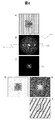
- FIG. 2 shows a schematic diagram of a reproduction procedure of the Fourier transform reproduction method
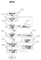
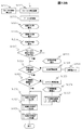
- FIGS. 3A and 3B show a reproduction flowchart of the Fourier transform reproduction method composed of steps S301 to S325.
- a in FIG. 2 is an interference microscope image that is an input / displayed hologram (S301, S302).
- B in FIG. 2 is a Fourier transform image of the hologram A that has been converted and displayed (S303, S304).
- a white distribution 35 in the center of the image is the power spectrum of the sample image, and two sidebands 36 on the left and right sides in the direction orthogonal to the stripes, that is, in the Fourier transform image B, include reproduced waves (including phase information).
- the phase information of the object wave is included as the first-order diffracted wave) and its conjugate wave (-1st-order diffracted wave).
- One of the two side bands 36 is selected (S305 to S307), and the image moved to the center of the image is C in the figure (S308 to S311).
- This movement to the center of the image corresponds to the movement of the origin of the calculation processing, and determination of the spot center (calculation center) of the sideband (S308) is performed by coordinate detection of the maximum value in the X-axis direction (S323), Y-axis direction. This can be done by detecting the maximum coordinate value (S324) and outputting the coordinate value (S325).
- phase distribution image E is clearly shown as an interference microscope image, a reference wave is given again to form an interference image.
- F it is also possible to display the phase distribution with equiphase lines in different directions as indicated by F in FIG.
- the Fourier transform reproduction method it is necessary to separate the power spectrum and sideband of the sample image from the Fourier transform image B, and the interval between the interference fringes can reduce the spatial resolution of the reproduced image (both amplitude distribution and phase distribution). decide.
- phase distribution is only a relative one, and in order to accurately indicate the physical quantity indicated by the phase distribution detected by holography, for example, the potential distribution or the magnetic field distribution, the entire phase distribution image including the background is appropriately It needs to be adjusted. For this purpose, it is necessary to repeat fine adjustments to the phase distribution while confirming the phase distribution image (S315, S316), and it is general that the reproduction method based on arithmetic processing is designed so that this method can be implemented. It is.
- step S317 cosine calculation processing is performed (S318), and the interference microscope image is displayed (S319). Amplitude distribution image data, phase distribution image data, and interference microscope image data obtained as necessary are stored (S320, 321, 322).
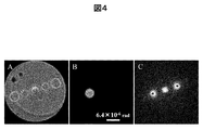
- FIG. 4A is a hologram of an electron spiral wave obtained by defocusing the diffraction image of the edge dislocation grating 45 of FIG. 1 and interfering with a transmitted wave up to ⁇ second order diffraction waves.
- the following edge dislocation lattice 45 is used.
- the hologram image data is input and displayed (S501 to S502). Then, a hologram is selected, for example, the left hologram is selected (S503 to S505).
- B in FIG. 4 is a hologram obtained by extracting only the hologram of the left-first order diffraction spot by mask processing (before centering), and C in FIG. 4 is a Fourier transform image of B (S506 to S511).
- a ring-shaped spiral wave diffraction spot is reproduced symmetrically.
- the left side corresponds to the direct image and the right side corresponds to the conjugate image.
- C in the figure is not the reproduced image of A, but reproduces one of the diffraction spots of the ring-shaped spiral wave on the diffraction surface (the left ring-shaped spot of C and its conjugate image (corresponding to the right)). is doing.
- a double ring (Bessel ring) is also observed outside the C ring. That is, the reproduction of the electron wave is completed by only one Fourier transform.
- an irradiation optical system is provided on the upper side of the sample, that is, on the upstream side in the direction in which the particle beam flows, and an imaging optical system is provided on the lower side of the sample, that is, on the downstream side in the direction in which the particle beam flows.
- the configuration of the interference type electron microscope as the particle beam apparatus system is listed in this example because the interference electron microscope is not only being developed as the most complicated system among particle beam apparatus systems, but also This is because the usage method is also versatile. For example, if all the lenses of the irradiation optical system are turned off in the system of the charged particle beam apparatus 1904 in FIG. 19, the electron beam from the particle source is directly irradiated onto the sample, and if the imaging optical system is also turned off, The simplest electron diffraction device. That is, the apparatus can be configured as a form simulating a neutron beam apparatus, a heavy particle beam, or an X-ray apparatus. However, the application target of each embodiment is not limited to the interference electron microscope having the configuration of FIG.
- an electron gun 1901 as a particle source is positioned at the most upstream part in the direction in which the electron beam flows, and the emitted electron beam is accelerated by the control of the particle beam control unit 1919 and the control unit 1949 of the acceleration tube 1940.
- the tube 1940 After accelerating the tube 1940 to a predetermined speed, it passes through condenser lenses 1941 and 1942 of the irradiation optical system controlled by the control units 1947 and 1948, and is adjusted to a predetermined intensity and irradiation region so that the diffraction grating 1935 above the sample. Is irradiated.
- the diffraction grating 1935 corresponds to the diffraction grating 16 shown in FIG.
- a transmitted wave and a diffracted wave transmitted through the diffraction grating 1935 are irradiated to the sample 1903.
- the electron beam that has passed through the sample 1903 is imaged by the objective lens 1905 controlled by the control unit 1959.
- This imaging action is taken over by the imaging lens systems 1961, 1962, 1963, 1964, which are controlled by control units 1969, 1968, 1967, 1966 after the objective lens 1905, and finally the observation recording of the electron beam apparatus.
- a final image 1908 is formed on the surface 1975.
- the image passes through an image detector 1979 such as a CCD camera and an image data controller 1978, and is observed on the screen of an image data monitor 1976, for example, or stored as image data in an image data recording device 1977.
- the transmitted wave and diffracted wave transmitted through the diffraction grating 1935 are irradiated to the sample 1903 without passing through the optical system, but the position of the crossover, which is the position of the image of the light source, can be arbitrarily selected by the irradiation optical system. is there.
- FIG. 19 depicts the case where the crossover is located between the diffraction grating and the sample.
- the image of the sample 1903 is magnified by the imaging lens systems 1961, 1962, 1963, and 1964 at the latter stage of the objective lens and formed on the observation recording surface 1975.
- the system control computer 1951 is used for diffraction.
- the electron gun 191 an acceleration tube 1940, each lens sample 1903, diffraction grating 1935, it controls the image detector 1979.
- the system control computer 1951 can also function as an image processing computer that performs various processes on previously stored image data.
- the system control computer 1951 and the control units 1938 to 1978 controlled by the system control computer 1951, the monitor 1952, and the interface 1953 may be collectively referred to as a control unit.
- the system control computer 1951 of the control unit executes various programs in order to realize the processing flowchart corresponding to each embodiment.
- the control units 1938 to 1978 are appropriately controlled, and further image data is processed.
- the particle beam system has been described based on a transmission electron microscope, charged particle beam devices such as ion microscopes, molecular beam devices, heavy particle beam devices, neutron beam devices, and broadly to electromagnetic wave devices such as X-rays. It may be used. Needless to say, the configuration of the optical system is changed based on the characteristics of each device. Many of the assumed particle beam devices are equipped with a vacuum exhaust system for evacuating the device to a vacuum because the propagation of the particle beam is limited to a vacuum, but there is a direct relationship with the present invention. Since there is no figure, illustration and description are omitted.
- a lensless Fourier transform holography reproducing method effective for electron spiral waves using the above-described transmission electron microscope system. That is, a lensless Fourier transform holography reproducing method using a charged particle beam device, the charged particle beam device being provided on the downstream side in the traveling direction of the irradiated charged particle beam and the irradiation optical system that irradiates the charged particle beam.
- a diffraction grating made of a material having transparency to a charged particle beam, a sample holder that can hold a sample on the diffraction surface of the diffraction grating, and an imaging optical system that forms an image of the charged particle beam that has passed through the diffraction surface
- an image detection unit that detects image formation by the imaging optical system, and a control unit that processes image data detected by the image detection unit.
- the control unit defines the opening area of the diffraction grating as the charged particle beam.
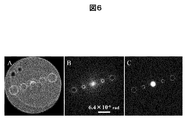
- FIG. 6 shows a reproduction image of the lensless Fourier transform holography of Example 1.
- a plurality of holograms can be recorded in a state where the same condition and the same time are sufficiently satisfied because they are based on the diffraction method by the diffraction grating 16. . That is, all holograms are recorded under the same conditions, and all information is considered equivalent. Therefore, in this embodiment, a reproducing method in which all holograms under the same recording conditions are collected will be described.
- A is a hologram
- B is a Fourier transform image (corresponding to a reproduced image in lensless Fourier transform holography)
- C is an electron diffraction image.
- FIG. 6B shows the result of Fourier transform of all the holograms in FIG. 6A, which is the same hologram as in FIG. 4A.
- FIG. 6C shows an in-focus image of A which is an electron diffraction pattern.
- B in FIG. 6 has a better SN ratio than C in FIG. 4, and the Bessel ring outside the ring-shaped diffraction spot is also observed well.
- the position and size of each ring-shaped diffraction spot in FIG. 6B and the vessel ring outside the diffraction spot coincide with C in FIG. From this, it can be seen that the lensless Fourier transform holography reproducing method in the present example can reproduce with higher accuracy than the conventional method.
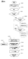
- FIG. 7 shows a flowchart (S701 to S705) of the procedure of the reproduction method in this embodiment.
- data recorded as a hologram is input and displayed as it is (S701, S702).
- Fourier transform of the hologram is performed (S703).
- a reproduction intensity distribution image B is obtained from the real part and the imaginary part of the obtained calculation result, displayed and stored (S704, S705).
- the reproduction method is lensless Fourier transform holography, it is possible to reproduce an image at a reverse space position and correct defocus. Furthermore, since the method based on the Fourier transform reproduction method, which is a conventional holographic reproduction method using a diffraction grating, can be implemented, image reproduction in the hologram recording space is also possible. Furthermore, by using an aberration correction method that is possible with the conventional reproduction method, it is possible to reproduce an image in a diffraction grating installation space. That is, according to the reproducing method of the present embodiment, as described above, it is possible to reproduce an image in three convenient spaces with one hologram.
- Example 2 is an example of a reproduction method in which the conventional Fourier transform reproduction method described above is applied to a spiral wave. That is, the charged particle beam diffracted by the diffraction grating is a spiral wave, and the control unit selects a part of the plurality of holograms and performs Fourier transform, and one of the plurality of sidebands in the obtained intensity distribution image.
- This is an embodiment of a method for reproducing lensless Fourier transform holography in which the selected sideband is subjected to inverse Fourier transform of the selected sideband and control is performed to display the obtained amplitude distribution image and phase distribution image.
- the hologram when a part is cut out as shown in FIG. 4B, the hologram has a form similar to a conventional electron beam holography hologram. That is, the two interference fringes of the diffracted wave and the transmitted wave from the diffraction grating are modulated by the phase distribution of the wave transmitted through the object (that is, the diffracted wave corresponds in this specification).
- the object corresponding to this object is a spiral wave.
- the interference fringes are superimposed on a ring-shaped image peculiar to the spiral wave.
- FIG. 8 shows the superimposed image as a hologram, and shows the result together with a reproduction result obtained by performing a conventional Fourier transform reproduction method.
- FIG. 8A shows a hologram obtained by cutting out only the ⁇ 1st order ring-shaped diffraction spot (the ⁇ 1st order diffraction spot on the left side of FIG. 4A), FIG. 8B shows the reproduced amplitude distribution image, and FIG. It is a reproduction phase image.
- the specific method of reproduction is as described with reference to FIG. 2, and the left side of the sideband after Fourier transform is selected at the time of reproduction.
- the determination method peculiar to the spiral wave must be used for determining the center point of the sideband, that is, the origin of the arithmetic processing at the time of reproduction. This will be described in a fifth embodiment, which will be described later, as a new calculation center determination method by the present inventors.
- the contrast (color density) indicating the phase distribution is a spiral wave having a topological number of 5 (spiral degree of 5) because the contrast modulation from white to black is repeated five times when it rotates clockwise.
- the amplitude distribution of B of FIG. 8 corresponds to the intensity distribution of A of FIG. 8, the intensity is almost lost at the center of the ring, but the phase is reproduced to almost the center of the ring. This point also shows the superiority of measuring the spiral wave with phase distribution.
- the hologram reproduction is also possible in exactly the same way for the + 1st order ring-shaped diffraction spot, that is, the + 1st order diffraction spot on the right side of FIG. D, E, and F in FIG. 8 show the hologram, reproduction amplitude distribution, and reproduction phase distribution, respectively.
- the right side is selected as the side band after Fourier transform during reproduction. This is because the angular relationship between the object wave and the reference wave is matched. That is, this is performed in order to make the left and right relationship between the object wave and the diffracted wave coincide with each other in FIGS.
- FIG. 8C and F in FIG. 8 indicate that the vortex winding direction is reversed, which also shows the relationship between the conjugate wave and the direct wave.
- the winding direction of the vortex is reversed depending on whether defocusing is positive or negative during hologram recording, that is, whether the focus is removed above or below the diffraction surface. This is whether the spherical wave state of the transmitted wave used as the reference wave is convex upward (under focus, ie, above the diffractive surface) or convex downward (over focus, ie, below the diffractive surface).
- the reference wave is a plane wave
- the vortex distribution itself as shown in FIG. 8 does not occur in the phase distribution.
- the generation of vortices is due to defocusing, and the manner in which the vortex-like phase distribution disappears by correcting defocusing on the diffraction surface will be described in Example 4 later.
- a predetermined area of data recorded as a hologram is input and displayed (S901, S902).
- a hologram is selected (A and D in FIG. 8), moved to the calculation origin, and subjected to Fourier transform to display an intensity distribution image (S903 to S911).
- a side band is selected and the center of a predetermined side band is extracted (S912 to S915). The determination of the center of the sideband (calculation center) (S915) will be described later with reference to FIG.
- Example 3 an example in which lensless Fourier transform holography is applied to a spiral wave and a Fourier transform reproduction method is applied to the hologram will be described.
- the present embodiment is an embodiment in the case where a spiral wave is used as an observation object as in the first and second embodiments. However, it is not limited to spiral waves.
- FIG. 10A is a hologram.
- the fifth-order edge dislocation grating used in FIGS. 4 and 6 is used as a diffraction grating.
- the diffracted wave up to ⁇ 2nd order interferes with the transmitted wave, and interference fringes are superimposed on each ring-shaped diffraction spot.
- the interval between the interference fringes reflects the angle between each diffracted wave and the transmitted wave, and the interference fringe interval on the ⁇ 2nd order diffraction spot is 1/2 of the interference fringe interval on the ⁇ 1st order diffraction spot. It has become. For this reason, even if the holograms of the ⁇ 1st order and ⁇ 2nd order diffraction spots are combined into an input image, they can be separated by filtering at the time of reproduction (corresponding to the mask process of B in FIG. 4).
- 10B is a Fourier transform image of A in FIG.
- This Fourier transform image matches the reproduced image on the diffraction surface shown in the first embodiment.
- the reproduced amplitude distribution image is shown in C of FIG. 10, and the reproduced phase distribution image is shown in D of FIG.
- the amplitude distribution image of C in FIG. 10 forms a ring-shaped distribution similarly to the hologram in A of FIG. 10 and can reproduce the characteristics of the spiral wave.
- the left diffraction spot recorded in the hologram A in FIG. 10 is a direct wave with a + 1st order diffracted wave diffracted by the edge dislocation grating
- the left diffraction spot becomes a conjugated wave with a ⁇ 1st order diffracted wave. .
- the phase change should have been reversed in these two waves.
- the left and right relationship between the diffracted wave and the transmitted wave is switched. That is, in the right side + 1st order diffracted wave, the right side has a diffracted wave (object wave) and the left side has a transmitted wave (reference wave), and the left side -1st order diffracted wave has a left side in FIG.
- the first-order diffracted wave is a conjugate wave.
- the conjugation was performed twice by selecting the ⁇ 1st order sideband (corresponding to the reproduced wave), and as a result, the phase distribution of the direct wave was restored. It is a thing. For this reason, the gradient of the phase change of the reproduction phase image of D in FIG. That is, the two reproduced waves D in FIG. 10 are completely identical in principle, including the amplitude and phase. By comparing and referring to each other using these two reproduced phase images, it is possible to improve the phase measurement accuracy.
- a predetermined area of data recorded as a hologram is input (S1101, S1102).
- Perform a Fourier transform A reproduction intensity distribution image B in FIG. 10 is obtained on the diffraction surface.
- S1103, S1104 The center of a predetermined side band is extracted (S1105 to S1108).
- the center point of the extracted sideband is moved to the origin of the calculation process (S1109 to S1111).
- the inverse Fourier transform is performed (S1112), and the reproduction amplitude image of C, the reproduction phase image of D, and the reproduction intensity distribution image of FIG. 10 can be obtained from the real part and the imaginary part of the calculation result (S1113 to S1124). .
- Example 4 is an example of a lensless Fourier transform holography reproducing method capable of defocus correction from a diffractive surface.
- defocusing from the diffraction surface is indispensable in order to superimpose the zeroth-order transmitted wave and the spiral wave (diffracted wave). Due to this defocusing, the reproduced wave (reproduced image) reproduced in Examples 2 and 3 faithfully reproduces the electron wave on the surface on which the hologram is recorded. It is also a wave in a state that is not a surface on which a diffraction grating is installed.
- both the amplitude distribution and the phase distribution can be reproduced according to the first embodiment.
- the surface on which the diffraction grating is arranged can be reproduced by using the aberration correction method in the conventional electron beam holography.
- a highly approximate theoretical formula is given for the modulation that the defocus or spherical aberration, astigmatism, etc. gives to the amplitude distribution and the phase distribution.
- Scherzer's formula The mathematical filter function using this equation is deconvolved immediately before the inverse Fourier transform is performed in the reconstruction method using the Fourier transform method. This is a method of correcting modulation such as focus distribution or correction of amplitude distribution and phase distribution.
- FIG. 12 shows a reproduction amplitude distribution (upper part of the figure) and a reproduction phase distribution (lower part of the figure) which are reproduction wave fields on the diffraction surface by the defocus correction method of the present embodiment.
- 13A and 13B are flowcharts illustrating the processing flow of the regeneration method according to the fourth embodiment.
- the phase distribution in the lower part of FIG. 12 shows that the contrast modulation from white to black is repeated three times when turning clockwise around the center of the spiral contrast, and the topological number is 3 (helicalness is 3). Is shown. This is different from the third embodiment because the third-order edge dislocation grating is used as a diffraction grating for producing the hologram of FIG.
- FIG. 12A is a reproduction amplitude distribution image at the hologram recording position
- FIG. 12B is a reproduction amplitude image in which the left diffraction wave is focused on the surface where the diffraction grating is arranged
- C is a diffraction grating for the right diffraction wave. It is the reproduction
- D, E, and F in the figure are reproduction phase images. 10A and 10B show no defocus correction, B and E correct the left spot, and C and F correct the right spot.
- the description from S1301 to S1311 overlaps with the description from S910 to S918 in FIG. 9A and FIG.
- a focus correction amount is input and focus correction calculation is executed (S1311, S1312), and an intensity distribution image, an amplitude distribution image, and a phase distribution image are displayed. This is performed (S1314 to S1316). Then, it is determined whether or not it is necessary to correct the focus correction (S1317). If necessary, the correction is performed, and the following processing (S1318 to S1328) is executed, but this is the same as S922 to S930, and the description is omitted. To do.
- the defocusing is further deepened in the opposite spot due to the conjugate wave. That is, since the left and right diffracted waves are in a conjugate relationship as described above, when one of the defocuses is corrected, the other defocus amount is increased by the same amount.
- the large defocus amount is apparent from the fact that both the amplitude image and the phase image are largely observed due to the image blur due to the image being out of focus. Note that in both B and C in FIG. 12, the central portion of the amplitude image is black after the defocus amount correction, but this is the core portion of the spiral wave, because the wave intensity was not propagated.
- the present embodiment is an embodiment of a lensless Fourier transform holography reproducing method for reproducing a spiral wave with high accuracy.
- the present invention relates to a sideband extraction method during hologram reproduction described in Embodiments 2 and 3 and a method of determining the center (computation center) of sidebands such as S915 and S1108.
- the calculation center (the calculation origin) at the time of extraction is not determined.
- the calculation center is shifted from the center of the sideband, a large change appears in the reproduced phase image. That is, the rotational center of the phase of the spiral wave is shifted, resulting in a distorted vortex-like reproduced phase image. That is, there is a possibility that a large artifact is introduced into the reproduced image by the arithmetic processing.
- An ideal reproduced phase image has a shape that is shifted in phase at every equal azimuth angle from the center of the helical wave.
- the reproduction phase images in FIGS. 8, 10, and 12 have shapes that are shifted in phase by equal azimuth angles from the center of the helical wave, and are almost ideal reproduction images.
- the pixel having the maximum intensity of the sideband (or the sub-pixel unit by image processing) can be determined as the center of the sideband in the reproduction calculation.
- the sideband has a ring shape and is not the maximum intensity. Since the intensity is canceled as a result of interference from each ring-shaped point, there is a theory that the point of the minimum intensity is selected in the reverse of the conventional method in theory.
- the diffracted wave after irradiating the sample with the spiral wave includes the sample information, and thus does not always have a ring shape with good symmetry. For this reason, considering an application for observing an actual sample, it is not realistic to set the pixel having the minimum intensity as the calculation center.
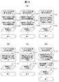
- the simplest method for determining the calculation center of the sideband is (1) a method of determining the center of symmetry of the ring shape as the calculation center, as shown in FIG. If the ring is circular (S1401 to S1403), elliptical (S1404 to S1406), or slightly deviated from them, the center position is based on the circular (including elliptical) fitting. Are determined (S1407 to S1408).
- This example is an example of a high-precision reproduction method using a reference hologram. That is, either one of the positive and negative of the diffraction spot of the diffracted charged particle beam, which is a spiral wave, is irradiated to the sample placed on the diffraction surface of the diffraction grating, and the hologram by the other diffraction spot is Fourier transformed to produce a side
- a phase distribution image is obtained.
- FIG. 14 (d) (4) a method (S1413 to S1415) of obtaining a calculation center using a conjugate wave hologram is suitable.
- the spiral wave irradiated to the sample 3 is set to one of the positive and negative diffraction spots.
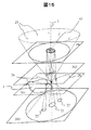
- the left-hand spot 26 in FIG. 15 is referred to as a conjugate spiral wave, and the right-hand spot 26 is referred to as a direct spiral wave.
- the phase information of the irradiation spiral wave in which the interaction with the sample 3 is not recorded is recorded in the conjugate wave.
- Only the hologram (right ring) by the right spot is extracted and subjected to Fourier transform, the calculation center is obtained by the above-described method, and applied to the Fourier transform pattern of the hologram (left ring) interacting with the sample. Since the Fourier transform is symmetric with respect to the origin, it can be implemented.
- the conjugate wave hologram not only determines the calculation origin of the object wave hologram, but also reproduces the phase distribution that directly reflects the incident spiral wave from the conjugate wave hologram.
- the conjugate wave hologram By taking the difference between the wavefront and the phase distribution of the object wave interacting with the sample, it is possible to reproduce the state of interaction between the sample and the spiral wave as a highly accurate and reliable process.
- the reproduction method of this embodiment can experimentally obtain highly accurate and reliable phase modulation of a helical wave without relying on simulation.
- Coordinate values (x, y) at the center of the ring that is, the center of the sideband (calculation center) are mathematically obtained by circular fitting of this ring-shaped pattern and recorded (S1612 to S1616).
- the calculation accuracy at this time is preferably as high as possible, but, for example, 1/10 of the pixel is used and the processing is performed in the sub-pixel.
- the ring center obtained here is the calculation origin in the reproduction processing of the present embodiment described next (S1705 in FIG. 17A).
- a direct wave is reproduced for a direct wave hologram and a conjugate wave is reproduced for a conjugate wave hologram. That is, two reproduction waves are obtained at a time.
- the phase modulation applied to the spiral wave (direct wave) by the object can be known by comparing and referring to the reproduced phase distribution.
- the obtained phase modulation is replaced with physical information by separate knowledge, and high-precision physical property measurement using a spiral wave is completed.
- the intensity of the central portion of the amplitude distribution is extremely small in the ring-shaped diffracted wave or the reproduced image in FIG. May be difficult to use practically.
- the fringe spacing of the interference fringes is twice different between the ⁇ 1st order and the ⁇ 2nd order of the diffracted wave. Therefore, even if four holograms are input simultaneously, the Fourier transform method simultaneously performs spatial frequency filtering, so that a reproduced image can be obtained individually. Therefore, in order to obtain a reproduced image of the entire input hologram, it is necessary to add up the obtained reproduced images.
- This example is also shown as G in FIG.
- control unit has been described using an example of a system control computer in which a program that realizes a part or all of them is used. It goes without saying that it may be realized by hardware by designing or the like. That is, all or part of the functions of the control unit may be realized by an integrated circuit such as ASIC (Application Specific Integrated Circuit) or FPGA (Field Programmable Gate Array) instead of the program.
- ASIC Application Specific Integrated Circuit
- FPGA Field Programmable Gate Array
Landscapes
- Physics & Mathematics (AREA)
- General Physics & Mathematics (AREA)
- Chemical & Material Sciences (AREA)
- Analytical Chemistry (AREA)
- Engineering & Computer Science (AREA)
- Computing Systems (AREA)
- Theoretical Computer Science (AREA)
- Mathematical Physics (AREA)
- Computer Vision & Pattern Recognition (AREA)
- Holo Graphy (AREA)
- Analysing Materials By The Use Of Radiation (AREA)
Abstract
荷電粒子線装置よるレンズレス・フーリエ変換ホログラフィーの高精度な再生方法を提供する。荷電粒子線の進行方向下流側に備えられ、荷電粒子線に対して透過性を有する材料からなる回折格子の回折面に試料を保持可能とし、回折面を通過した荷電粒子線を結像して、結像を検出する。回折格子の開口領域を、荷電粒子線の回折格子への照射領域よりも小さくして、回折格子により回折された荷電粒子線の照射領域が、回折格子を透過した荷電粒子線の照射領域内にある状態として画像データを得(S701、S702)、この画像データに基づき得られる複数のホログラムをフーリエ変換し(S703)、強度分布像を表示、記憶する(S703、S704)。
Description
本発明は、回折効果を利用する粒子線装置、特に回折格子を用いたホログラフィーに有効な再生技術に関する。
電子線やイオンビームなどの荷電粒子線は、真空中を伝搬させなければならないこと、波長が数pmの桁と短く、偏向角度が小さいこと、光学におけるハーフミラーの様な有効なビームスプリッターがないことなどから、光学ベンチにおけるマッハツェンダー干渉計のごとく複数の光学経路を作り出してそれぞれ独立に光学系を構成することは難しい。また、紫外線やX線など短波長の電磁波では、その良透過性から有効な光学素子を構成することが難しく、さらには中性子線や分子線・重粒子線などの粒子線ではそもそも光学素子がない。そのため、光源から検出器までの間に試料を配し、経路伝搬による試料での散乱・吸収像の観察か、あるいは干渉・回折効果に基づく回折パターンの観察が実施されているのみである。すなわち、上記いずれの電磁波装置、粒子線装置においても、1経路の光学系が用いられており、試料を透過した透過ビームにも散乱・回折ビームにも同一のレンズや同一の偏向器などを用いなければならず、同一の光学条件を適用した計測法が用いられている。
上記装置類の中では、電子線を用いた電子顕微鏡が最も開発が進んでおり、電子レンズ、偏向器、電子線バイプリズムなど様々な光学素子が実現されているが、原理的に電子線の伝搬は真空中でなければならず、1つの真空排気された鏡筒内に1経路の光学系で構成されているのみである。電子線干渉において唯一有効なビームスプリッターである電子線バイプリズムを利用した場合でも、その偏向角度は最大でも10-3 radと小さく、2つの経路に対して、同一のレンズ、偏向器を用いなければならないという制約は、他の粒子線装置類と何ら変わらない。そのため、同一視野内に電子線照射の粗密を作り出すことは難しく、電子線照射に起因した試料の帯電効果や試料損傷の程度を2つの照射条件を同時に比較参照しながら観察すること、とりわけその変化の過程を観察することは困難であった。
このような課題に対する対策ではないが、電子線を用い、レンズを使用するフーリエ変換ホログラフィーとして、1鏡筒内に2つの照射条件を作り出す手法を開示する非特許文献1と、X線で2つの照射条件を作り出す可能性を開示した特許文献1がある。非特許文献1は、アモルファス薄膜からなる拡散板を透過した電子線の対物レンズの後焦点面を試料面として利用する手法で、拡散板で散乱を受けずに透過した電子線は光軸上にスポットを結び、アモルファス膜でランダムに散乱された電子線は後焦点面で平面上に広がる現象を利用したもので、光軸上のスポットと平面状部分の電子線との干渉を利用する。
特許文献1は非特許文献1の拡散板に変わり、孔を設けたゾーンプレートを利用するもので、ゾーンプレートのレンズ効果による焦点がスポットとなり、孔を透過したX線が平面波となる。いずれの例もホログラフィーとしては実用的でなく普及していない。また、レンズの存在しない粒子線装置では、実現不可能な構成である。
R. Lauer; Optik, 67 (1984) 291.
B. J. McMorran et al., Science 331 (2011) 192.
G. W. Stroke et al., J. Opt. Soc. Am. 55 (1965) 1327.
上述のように紫外線やX線などの短波長の電磁波装置や粒子線装置では、1経路の光学系、すなわち、試料を透過した透過ビームにも散乱・回折ビームにも同じレンズや同じ偏向器など同一の光学条件を適用した計測法しか利用できないため、同一視野内に2つの光学状態による粒子線照射の粗密を作り出すことは難しく、広範囲を照射しながら、局所的に照射量を増やして明るさを稼ぎ高倍率観察すること、あるいは局所的な試料状態の照射量依存性を、周辺部を参照してその変化を観察すること、また加工などにおいては、全体を一定の低量照射しながらピンポイントに局所高密度照射を施し、加工・調整などを実施することは困難であった。
本発明者は、上述の課題を解決し、同一視野内に二つの光学状態による粒子線照射の粗密を作り出すことが可能な粒子線装置、観察法、及び回折格子を提案した(PCT/JP2017/014393)。すなわち、粒子線装置であって、粒子線を発生する粒子線源と、粒子線を試料に照射する照射部と、試料を保持するための試料保持部と、試料を透過した粒子線を取得するための検出部と、照射部における粒子線の進行方向下流側で、試料の粒子線の進行方向上流側に備えられ、粒子線に対して透過性を有する材料で構成される回折格子と、回折格子の当該装置の光軸上への着脱と移動を可能とする保持装置とを備え、回折格子の開口領域は粒子線の回折格子への照射領域よりも小さい構成の粒子線装置、観察法、および回折格子を発明した。また、その一実施態様として、回折格子からの透過波と回折波との間に可干渉性を保持して複数のホログラムを得る、電子顕微鏡によるフーリエ変換ホログラフィーを実現して開示した。
上記の構成にあっては、試料への照射光学系中に回折格子を用いることにより、入射電子線がブラッグ回折を受けて複数のビームに分離する。この回折波同士は光軸を挟んで位相分布が反転しているが、その他の条件は全く等しく電子光学系を通過する。そのため、光学系の与える収差やノイズなどの状態は全く同じであり、これらの同一条件性も、時間的な同時性も完全に確保されている。この複数の電子線を試料の各部位、あるいは試料の無い部分に照射・通過させ記録することにより、一鏡体複数ビーム光学系が実現できる。このようにして得られた複数の画像を比較参照することにより、極めて高い計測精度を得ることが可能となる。
本願発明の目的は、このような荷電粒子線装置よる、回折に基づく複数の荷電粒子線を利用した複数のホログラムの同時記録という特徴を活かしたホログラフィーの再生方法、並びにプログラムを提供することにある。
上記の目的を達成するため、本発明においては、荷電粒子線装置よるホログラフィーの再生方法であって、荷電粒子線装置は、荷電粒子線を照射する照射光学系と、照射される荷電粒子線の進行方向下流側に備えられ、荷電粒子線に対して透過性を有する材料からなる回折格子と、回折格子の回折面に試料を保持可能な試料保持部と、回折面を通過した荷電粒子線を結像する結像光学系と、結像光学系による結像を検出する画像検出部と、画像検出部が検出した画像データを処理する制御部とを備え、制御部は、回折格子の開口領域を、荷電粒子線の回折格子への照射領域よりも小さくして、回折格子により回折される荷電粒子線の照射領域が、回折格子を透過した荷電粒子線の照射領域内にある状態とし、画像データに基づき得られる複数のホログラムの少なくも一つを選択し、選択したホログラムをフーリエ変換するよう制御するホログラフィーの再生方法を提供する。
また、上記目的を達成するため、本発明においては、荷電粒子線を照射する照射光学系と、照射される荷電粒子線の進行方向下流側に備えられ、荷電粒子線に対して透過性を有する材料からなる回折格子と、回折格子の回折面に試料を保持可能な試料保持部と、回折面を通過した荷電粒子線を結像する結像光学系と、結像光学系による結像を検出する画像検出部から得られる画像データを処理する制御部で実行されるホログラフィーの再生プログラムであって、制御部を、回折格子の開口領域を、荷電粒子線の回折格子への照射領域よりも小さくし、回折格子により回折された荷電粒子線の照射領域が、回折格子を透過した荷電粒子線の照射領域内にある状態とし、画像データに基づき得られる複数のホログラムの少なくも一つを選択し、選択したホログラムをフーリエ変換するよう制御するホログラフィーの再生プログラムを提供する。
本発明によれば、回折に基づく複数の荷電粒子線を利用した複数のホログラムからの再生像を比較参照することにより、再生像の精度向上を可能とする再生方法を提供することができる。
以下、本発明の種々の実施例を説明するに先立ち、その理解を容易にするため、上述した国際特許出願の明細書で、本発明者が開示した電子顕微鏡におけるレンズレス・フーリエ変換ホログラフィーの原理とその再生法を説明する。なお、以下の説明においては、電子線を用いた透過型電子顕微鏡でのホログラム再生を例示して説明するが、Heイオン顕微鏡などの荷電粒子線装置に対しても適用できる。
図1は、回折格子16からの透過波と回折波との間に可干渉性が保持されている場合の電子顕微鏡、及びその観察法を説明するための図である。この場合には、透過波と回折波のいずれか一方を物体波、他方を参照波として、ホログラフィーを実現できる。すなわち、電子顕微鏡において回折格子を用いた本構成を採用すると、電子線バイプリズムなどを使用しなくても電子線ホログラフィーが実現できる。
同図では透過波21と回折波22との干渉の様子を示している。回折波22に空間的な広がりを持たせ、透過波21との干渉縞84を例示しやすくするため、挿入する回折格子16をらせん波生成用の刃状転位格子45とし、回折波22としてはリング状の回折スポット26を説明の対象とするが、らせん波を用いる場合に限定するものではない。
ここで、らせん波とは、波面(等位相面)がらせん形状をした波の総称で、粒子の軌道で考えた場合には空間を伝搬する電子線などの荷電粒子線が渦を巻くように伝搬するビームであり、らせん状波面のコア、もしくは渦状ビームの中心には軌道角運動量が保持されていると考えられている。
このらせん波の観察には粒子描像の考え方が先行しており、ビーム形状が逆空間でリング状になることを利用した観察方法が主流となっている。一方、試料との相互作用を計測する手法としては、試料透過後の、ビームの強度分布の変化、エネルギー分布のシフト、あるいは照射による試料形状の変化、などの報告があるがまだ一般的にはなっていない。その大きな理由は、らせん波の試料との相互作用が小さく、照射の効果を十分に検出できていない点にある。
らせん波は、その波面形状に特徴を持つ波であるため、計測対象の特徴は波面にこそ反映されているはずで、そのためにはらせん波の位相を計測する必要がある。しかし、現在までのところ、らせん波の位相計測に関する報告は、実用的な意味おいてはまだない(非特許文献2参照)。ホログラフィーは波の位相分布を検出する最も実効的な手法であり、実用的ならせん波の利用空間である逆空間においては、位相計測に必須となる参照波を得る方法として、本発明者がこれから説明するデフォーカスによる方法、すなわちレンズレス・フーリエ変換ホログラフィーを実現した。
図1の刃状転位格子45の格子を刻んだ部分とその外側を透過した波も、刃状転位格子45で回折された波もクロスオーバー26を結ぶ光軸2上の位置(高さ)は同じである。このクロスオーバー26面は光源の像面であって、回折格子16にとっての逆空間である回折面301に対応している。そのため、回折格子16がらせん波生成用の刃状転位格子45である場合、透過波のスポット26に加えてリング状の回折スポット26が生成される。なお回折面301の上下にアンダーフォーカス面302、オーバーフォーカス面303がある。
刃状転位格子45よりも広範囲を照射した入射波25は収束角も大きく、光軸2に沿って伝搬すると、刃状転位格子45を透過してから急速に縮小され回折面301上でスポットを結ぶ。その後、急速に拡大される。透過波21と同様に回折波22も伝搬によって縮小され、回折面301で最小サイズの回折スポット26を結んだ後、拡大される。しかし、この回折波22のサイズの変化の程度は、透過波21の変化と比較するとはるかに小さい。従って、回折面301からの距離を適切に選びデフォーカス面を作り出せば、透過波21と回折波22との重畳する空間を観察することができる。この透過波21と回折波22とが、空間的に可干渉距離の範囲内であるとき、これら2波の干渉が観察される。すなわち、逆空間(回折空間)からのデフォーカスを利用してレンズレス・フーリエ変換ホログラフィーが実現できる。
この光学系の特徴は、物体と同じ位置、ただし物体の存する光軸に垂直な平面内で、かつ光軸から離れた位置に参照波の光源(原理的には点光源)を配置し、物体から伝搬していく物体波と点光源から伝搬していく参照波を重ね合わせたホログラムを記録するところにある。物体の様々な位置で散乱を受けた物体波は、それぞれがその位置を射出点とし、様々な初期位相を持った点光源の集合体と考えられる。本光学系は、この波の集合体すなわち物体波に、単一の点光源からの波を参照波として重畳する光学系である。それぞれの波は伝搬に基づくフーリエ変換を経ているため、レンズを用いずとも物体波と参照波は逆空間(回折空間あるいは回折面、すなわちフーリエ変換面)で重畳することになり、フーリエ変換ホログラフィーと等価な干渉像(ホログラム)を記録できることから、「レンズレス・フーリエ変換ホログラフィー」の名称が与えられている。非特許文献3には、レーザー光の場合のレンズレス・フーリエ変換ホログラフィーについて開示されている。
このフーリエ変換ホログラフィーを含むレンズレス・フーリエ変換ホログラフィーの再生法の特徴は、一回のフーリエ変換で再生像が得られる点、および光軸を挟んで相対する位置に直接像と共役像が向かい合わせで再生される点にある。非特許文献1には、電子線を用い、レンズを使用する電子線フーリエ変換ホログラフィーが開示されている。
以下に、電子線ホログラフィーの再生方法として主流となっているフーリエ変換再生法の概要について説明する。従来のレンズを使用した電子線ホログラフィーはイメージホログラフィーに分類され、顕微鏡像に干渉縞が重畳された干渉顕微鏡像であることを特徴としている。ホログラムがそのまま干渉顕微鏡像であり、電子波の位相変調が重畳された干渉縞のシフトとして記録されている。この干渉縞のシフト量の分布を可視化することがイメージホログラフィーの再生方法である。ホログラムが像になっているため、ホログラム自体には結像能力は無く、レーザー光を使った光学再生の場合には、レンズを用いた結像光学系が必要となる。
従来のフーリエ変換再生法は、レーザー光学系による再生方法をそのまま計算機上に移し変えた手法で、電子線ホログラフィーにおける演算処理再生法の最も初期から用いられてきた方法であり、現在でも主流の再生方法である。
図2にフーリエ変換再生法の再生手順の模式図を、図3A、図3BにステップS301~S325からなるフーリエ変換再生法の再生フローチャート図を示す。図2のAは入力・表示されたホログラムである干渉顕微鏡像である(S301、S302)。図2のBは変換・表示されたホログラムAのフーリエ変換像である(S303、S304)。像の中心部にある白い分布35が試料像のパワースペクトルであり、縞と直交する方向、すなわちフーリエ変換像B中の左右にある2つのサイドバンド36が、位相情報を含んでいる再生波(1次回折波)とその共役波(-1次回折波)として物体波の位相情報を含んでいる。
この2つのサイドバンド36のいずれか一方を選択し(S305~S307)、画像の中心部に移動させた像が同図のCである(S308~S311)。この画像中心部への移動は、演算処理の原点の移動に該当し、サイドバンドのスポット中央(演算中央)の決定(S308)は、X軸方向最大値の座標検出(S323)、Y軸方向最大値の座標検出(S324)、座標値の出力(S325)で行うことができる。
続いて、同図のCをフーリエ逆変換し(S312)、計算結果の実部と虚部より、それぞれ振幅分布像Dと位相分布像Eを得、表示することができる(S313、S314)。位相分布像Eを干渉顕微鏡像として明示する場合には、改めて参照波を与えて干渉像とする。例えば、同図のFの様に位相分布を別方向の等位相線で表示することも可能である。いずれにしてもフーリエ変換再生法では、フーリエ変換像Bで試料像のパワースペクトルとサイドバンドの分離を行う必要があり、干渉縞の間隔が再生像(振幅分布、位相分布とも)の空間分解能を決定する。
なお、位相分布はあくまでも相対的なものであり、ホログラフィーにより検出される位相分布が示す物理量、例えば、電位分布や磁場分布などを的確に示すために、位相分布像の背景を含む全体を適切に調整する必要がある。このためには、位相分布像を確認しながら位相分布に対する微調整を繰り返す(S315、S316)必要があり、演算処理による再生法にはこの方法が実施できるように配慮されていることが一般的である。
さらに、このフーリエ変換再生法では、ホログラムを記録した際に用いられたレンズの球面収差や非点収差、および試料像のデフォーカスを補正することが可能である。これは結像の理論式(収差関数)が既知の場合に、同図のCに収差関数をデコンボリューションして相殺し、その後フーリエ逆変換を実施して、上記収差やデフォーカスの無い再生像である振幅分布像Dと位相分布像Eをともに得る手法である。この手法は、電子線ホログラフィーでは、一般的な収差補正法として利用されている。
また、ステップS317で干渉顕微鏡像要の場合、コサイン演算処理し(S318)、干渉顕微鏡像の表示を行う(S319)。必要に応じて得られた振幅分布像データ、位相分布像データ、干渉顕微鏡像データをそれぞれ記憶する(S320、321、322)。
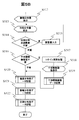
続いて、レンズレス・フーリエ変換ホログラフィーの再生手法について説明する。フーリエ変換ホログラフィーやレンズレス・フーリエ変換ホログラフィーにおける再生方法は、一回のフーリエ変換のみである。この手順を図4の電子らせん波のホログラム、図5A、図5BのステップS501~S525からなる再生処理フローチャートを用いて説明する。なお、図5BのステップS512~S522については、強度分布像データ記憶(S520)以外は、図3BのステップS313~S322と重複するので説明を省略する。
図4のAは、図1の刃状転位格子45の回折像をデフォーカスし、±2次の回折波までの透過波と干渉させて得た電子らせん波のホログラムであり、回折格子として5次の刃状転位格子45を用いている。このホログラムの画像データが入力され、表示される(S501~S502)。そして、ホログラムの選択を行い、例えば左側のホログラムを選択する(S503~S505)。図4のBは左側-1次の回折スポットのホログラムのみをマスク処理により抽出したホログラム(センタリング前)、同図のCはBのフーリエ変換像である(S506~S511)。左右対称にリング状のらせん波の回折スポットが再生されていることがわかる。図4のCの場合には、左側が直接像、右側が共役像に該当する。なお、同図のCはAの再生像ではなく、回折面でのリング状のらせん波の回折スポットのうちの一つ(Cの左側リング状スポットとその共役像(右側に該当))を再生している。これはCのリングの外側にも2重のリング(ベッセルリング)が観察されているところからも明らかである。すなわち、1回のフーリエ変換のみにて、電子波の再生が完了している。
以上概説した本発明者が先に発明した回折格子を用いたレンズレス・フーリエ変換ホログラフィーの原理を踏まえ、レンズレス・フーリエ変換ホログラフィーの再生方法、及びそのプログラムの各種の実施例について順次説明する。まず各実施例の再生方法に共通して用いられる粒子線装置システムとして、透過型電子顕微鏡を使った構成例について図19を用いて説明する。
図19の荷電粒子線装置1904として、100kVから300kV程度の加速電圧を持つ汎用型の電子顕微鏡を想定している。そのため試料の上側、すなわち粒子線の流れる方向の上流側には照射光学系を、試料の下側、すなわち粒子線の流れる方向の下流側には結像光学系を備えている。
粒子線装置システムとして干渉型の電子顕微鏡の構成を本実施例に挙げたのは、粒子線装置システムの中では干渉型電子顕微鏡が最も複雑なシステムとして開発が進んでいるだけでなく、装置の利用手法においても汎用性を併せ持っているためである。例えば、図19の荷電粒子線装置1904のシステムで照射光学系のレンズをすべてオフすれば、粒子源からの電子線を直接試料に照射する形態となり、合わせて結像光学系もオフすれば、最もシンプルな電子回折装置となる。すなわち、中性子線装置や重粒子線、X線装置を模擬する形態として装置を構成することができる。ただし、各実施例の適用対象を図19の構成を持つ干渉型電子顕微鏡に限定するものではない。
図19において、粒子源である電子銃1901が電子線の流れる方向の最上流部に位置し、粒子線の制御ユニット1919と加速管1940の制御ユニット1949の制御により、放出された電子線は加速管1940にて所定の速度に加速された後、制御ユニット1947、1948に制御される照射光学系のコンデンサレンズ1941、1942を経て、所定の強度、照射領域に調整されて試料上部の回折格子1935に照射される。この回折格子1935は、図1に示した回折格子16に対応している。回折格子1935を透過した透過波と回折波は試料1903に照射される。試料1903を透過した電子線は、制御ユニット1959に制御される対物レンズ1905にて結像される。この結像作用は、対物レンズ1905よりも後段の制御ユニット1969、1968、1967、1966に制御される結像レンズ系1961、1962、1963、1964に引き継がれ、最終的に電子線装置の観察記録面1975に最終像1908が結像される。その像はCCDカメラなど画像検出器1979と画像データコントローラ1978を経て、例えば画像データモニタ1976の画面上で観察したり、画像データ記録装置1977に画像データとして格納される。
回折格子1935を透過した透過波と回折波は、光学系を介さずに試料1903に照射されるが、光源の像の位置であるクロスオーバーの位置は、照射光学系によって任意に選択が可能である。図19は、クロスオーバーが回折格子と試料との間に位置する場合を描いている。これにより、試料1903の像は対物レンズ後段の結像レンズ系1961、1962、1963、1964で拡大され、観察記録面1975に結像される。
これら装置は、全体としてシステム化されており、オペレータはモニタ1952の画面上で装置の制御状態を確認するとともに、インターフェース1953を介して、各種プログラムが実行され、システム制御コンピュータ1951を用いて、回折格子1935の制御ユニット1938、試料1903の制御ユニット1939、第2照射レンズ1942の制御ユニット1947、第1照射レンズ1941の制御ユニット1948、加速管1940の制御ユニット1949、対物レンズ1905の制御ユニット1959、第4結像レンズ1964の制御ユニット1966、第3結像レンズ1963の制御ユニット1967、第2結像レンズ1962の制御ユニット1968、第1結像レンズ1961の制御ユニット1969、画像検出器1979の制御ユニット1978を制御することにより、電子銃191、加速管1940、各レンズ、試料1903、回折格子1935、画像検出器1979などを制御できる。また、システム制御コンピュータ1951は、先に記憶した画像データに対して種々の処理を行う画像処理コンピュータとして機能することも可能である。本明細書において、システム制御コンピュータ1951と、それにより制御される各制御ユニット1938~1978、更にはモニタ1952、インターフェース1953を総称して制御部と呼ぶ場合がある。これから詳述する各種のレンズレス・フーリエ変換ホログラフィーの再生方法においては、各実施例に対応する処理フローチャートを実現するために、制御部のシステム制御コンピュータ1951は各種プログラムを実行することにより制御部の各制御ユニット1938~1978を適宜制御し、更に画像データの処理を行う。
なお、粒子線装置システムとして透過型電子顕微鏡に基づいて説明したが、イオン顕微鏡などの荷電粒子線装置、および分子線装置、重粒子線装置、中性子線装置、そして広くはX線など電磁波装置に用いてもよい。その際に、それぞれの装置の特性に基づいて光学系の構成が変更されるのは、言うまでもない。なお、想定される粒子線装置の多くのものは、粒子線の伝搬が真空内に限られるため装置を真空に排気するための真空排気系などを備えているが、本発明と直接の関係が無いため、図示、および説明は省略した。
次に実施例1として、上述した透過型電子顕微鏡システムを用いて、電子らせん波に効果的なレンズレス・フーリエ変換ホログラフィーの再生方法の実施例を説明する。すなわち、荷電粒子線装置よるレンズレス・フーリエ変換ホログラフィー再生方法であって、荷電粒子線装置は、荷電粒子線を照射する照射光学系と、照射される荷電粒子線の進行方向下流側に備えられ、荷電粒子線に対して透過性を有する材料からなる回折格子と、回折格子の回折面に試料を保持可能な試料保持部と、回折面を通過した荷電粒子線を結像する結像光学系と、結像光学系による結像を検出する画像検出部と、画像検出部が検出した画像データを処理する制御部と、を備え、制御部は、回折格子の開口領域を、荷電粒子線の回折格子への照射領域よりも小さくし、回折面に作られる回折格子により回折された荷電粒子線の照射領域が、回折格子を透過した荷電粒子線の照射領域内にある状態とし、画像データに基づき得られる複数のホログラムをフーリエ変換するよう制御するレンズレス・フーリエ変換ホログラフィー再生方法の実施例である。
図6に実施例1のレンズレス・フーリエ変換ホログラフィーの再生像を示す。図1を使って説明した電子顕微鏡によるレンズレス・フーリエ変換ホログラフィーでは、回折格子16による回折法に基づくため複数のホログラムが、同一条件性、同一時間性を十分に満たした状態で記録できている。すなわち、全ホログラムが同一条件下での記録によるもので、すべての情報は等価だと考えられる。そこで本実施例では、これら同一記録条件下のホログラム全部をまとめた再生法について説明する。同図において、Aはホログラム、Bはフーリエ変換像(レンズレス・フーリエ変換ホログラフィーにおいては再生像に該当する)、Cは電子回折像を示す。
図4のAと同じホログラムである図6のAのホログラム全部をまとめてフーリエ変換した結果を図6のBに示す。また、図6のCには電子回折パターンであるAのインフォーカス像を示す。同図に明らかなように、図6のBはCとよく一致している。さらに図6のBは、図4のCと比較してSN比もよく、リング状回折スポットの外側のベッセルリングも良く観察されている。図6のBの各リング状回折スポット、および回折スポット外側のベッセルリングの位置とサイズは図6のCと一致している。このことから、本実施例におけるレンズレス・フーリエ変換ホログラフィーの再生方法は、従来よりも高い精度で再生ができていることがわかる。
図7に、本実施例での再生方法の手順のフローチャート(S701~S705)を示す。まず、ホログラムとして記録されたデータをそのまま入力して表示する(S701、S702)。そしてホログラムのフーリエ変換を実施する(S703)。そして、得られた計算結果の実部と虚部より、再生強度分布像Bを得て、表示して記憶する(S704、S705)。
このように、実施例1のレンズレス・フーリエ変換ホログラフィーの再生法によれば、複数のホログラムからの再生像を比較参照することにより再生像の精度向上が可能となる。また、回折波に基づくため、ホログラム記録時の直接波と共役波の分離と再生時の直接波と共役波の分離を任意に実施できる。すなわち、
(1)直接波(記録時)→直接波(再生時)=直接波の位相分布、
(2)共役波(記録時)→共役波(再生時)=直接波の位相分布、という2波の再生が可能である。
(1)直接波(記録時)→直接波(再生時)=直接波の位相分布、
(2)共役波(記録時)→共役波(再生時)=直接波の位相分布、という2波の再生が可能である。
すなわち、理論的には完全同時刻に記録した直接波を2つ再生できるため、互いに比較参照することにより、位相計測精度の向上が可能である。また、レンズレス・フーリエ変換ホログラフィーとしての再生方法なので、逆空間位置での像再生、デフォーカスの補正が可能である。更に回折格子を用いた従来のホログラフィー再生手法であるフーリエ変換再生法に基づいた手法も実施可能な構成であるため、ホログラム記録空間での像再生も可能である。また更に、従来の再生法で可能な収差補正法を利用することにより、回折格子設置空間での像再生も可能である。すなわち、本実施例の再生法によれば、上述の通り1枚のホログラムにより都合3つの空間での像再生が可能となる。
実施例2は、先に説明した従来のフーリエ変換再生法をらせん波に適用した再生方法の実施例である。すなわち、回折格子により回折された荷電粒子線がらせん波であり、制御部は、複数のホログラムの一部を選択してフーリエ変換し、得られた強度分布像中の複数のサイドバンドの一つを選択し、選択したサイドバンドをフーリエ逆変換し、得られる振幅分布像と位相分布像を表示するよう制御するレンズレス・フーリエ変換ホログラフィーの再生方法の実施例である。
図4、図6のAで示したホログラムは、図4のBのごとく一部を切り出した場合には、従来の電子線ホログラフィーによるホログラムと類似の形態をしている。すなわち、回折格子からの回折波と透過波との2波の干渉縞が、物体を透過した波(すなわち、本明細書では回折波が該当する)の位相分布で変調を受けた形状である。図4、図6ではこの物体に該当するものがらせん波ということになる。すなわち、図4、図6のAに見るように、らせん波に特有のリング状の像に対して干渉縞が重畳された像となっている。図8にこの重畳された像をホログラムととらえ、従来のフーリエ変換再生法を実施した再生結果と共に示した。
図8のAが-1次のリング状回折スポット(図4のAの左側の-1次回折スポット)のみを切り出したホログラム、図8のBが再生された振幅分布像、図8のCが再生位相像である。再生の具体的な方法は図2で説明した通りであり、再生時にはフーリエ変換後のサイドバンドは、左側を選択したものである。但し、サイドバンドの中心点、すなわち再生時の演算処理の原点の定め方は、らせん波に特有の決定方法を用いなければならない。これについては、本発明者による新しい演算中心決定の手法として後述の実施例5で説明する。
図8のBはリング状の分布を持ち、図8のCは外側から内側への流れと見たときに時計回りの渦状の形状を成している。一方、位相分布を示すコントラスト(色の濃度)は、時計方向に周回すると白から黒へのコントラストの変調が5回繰り返されており、トポロジカル数5(らせん度5)のらせん波となっていることがわかる。図8のBの振幅分布は、図8のAの強度分布に対応するため、リング中央部で強度がほとんど失われているが、位相はリングのほぼ中央部まで再生されている。この点もらせん波を位相分布で計測することの優位性を示している。
+1次のリング状回折スポット、すなわち、図4のAの右側の+1次の回折スポットについても、全く同様にホログラム再生が可能である。図8のD、E、Fにそのホログラム、再生振幅分布、再生位相分布各々を示す。但し、この時は再生時にはフーリエ変換後のサイドバンドは、右側を選択している。これは物体波と参照波との角度関係を一致させるためである。すなわち、物体波と回折波との左右の関係を図8のA、B、Cと図8のD、E、Fで一致させるために行ったものである。
また、図8のFの再生位相分布では時計方向に周回したときのコントラストが黒から白に変調している。このコントラストの変調は、図8のCと図8のFとでは反転している。これは再生されたらせん波の渦の巻き形状が反転していることを示しており、記録時の図8のCを共役波とすると、図8のFが直接波の関係になっていることを示している。
図8のCとFとで渦の巻き方向が反転しているが、これも共役波と直接波との関係を示すものである。なお、この渦の巻き方向は、ホログラム記録時のデフォーカスの正負、すなわち、回折面の上下どちらにフォーカスを外したかにより反転する。これは、参照波として用いている透過波の球面波状態が上に凸(アンダーフォーカス、すなわち回折面の上側の場合)か、下に凸(オーバーフォーカス、すなわち回折面の下側の場合)かに依存している。参照波が平面波の場合には、位相分布に図8に示したような渦状の分布自体は発生しない。渦の発生はデフォーカスによるもので、回折面に対する、デフォーカスの補正により渦状の位相分布が消える様子は、後の実施例4で説明する。
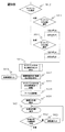
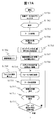
以下に、本実施例の再生方法の手順を図9A~図9Cの処理フローチャート(S901~S930)を参照して説明する。
(1)ホログラムとして記録されたデータの所定の領域を入力して表示する(S901、S902)。
(2)ホログラムを選択(図8のA、D)して演算原点へ移動しフーリエ変換を実施して、強度分布像表示する(S903~S911)。
(3)サイドバンドを選択し、所定のサイドバンドの中央を抽出する(S912~S915)。なお、このサイドバンドの中央(演算中央)の決定(S915)については、後に図14を用いて説明する。
(4)抽出されたサイドバンドの中央点を演算処理の原点に異動させる(S916~S919)。
(5)フーリエ逆変換を実施する(S920)。
(6)計算結果の実部と虚部より、再生振幅像(図8のB、E)、再生位相像(図8のC、F)、および再生強度分布像を得て表示並びに記憶する(S921~S930)。
(1)ホログラムとして記録されたデータの所定の領域を入力して表示する(S901、S902)。
(2)ホログラムを選択(図8のA、D)して演算原点へ移動しフーリエ変換を実施して、強度分布像表示する(S903~S911)。
(3)サイドバンドを選択し、所定のサイドバンドの中央を抽出する(S912~S915)。なお、このサイドバンドの中央(演算中央)の決定(S915)については、後に図14を用いて説明する。
(4)抽出されたサイドバンドの中央点を演算処理の原点に異動させる(S916~S919)。
(5)フーリエ逆変換を実施する(S920)。
(6)計算結果の実部と虚部より、再生振幅像(図8のB、E)、再生位相像(図8のC、F)、および再生強度分布像を得て表示並びに記憶する(S921~S930)。
実施例3として、レンズレス・フーリエ変換ホログラフィーをらせん波に適用し、そのホログラムに対してフーリエ変換再生法を適用する実施例を説明する。本実施例は、実施例1、2と同様に観察対象としてらせん波を用いた場合の実施例である。但し、らせん波に限定するものではない。
図10のAはホログラムである。これまでと同じ図4、図6で用いた5次の刃状転位格子を回折格子として用いている。図10のAに明らかなように、この±2次までの回折波が透過波と干渉しており、各々のリング状の回折スポットに干渉縞が重畳されている。この干渉縞の間隔は各回折波と透過波との角度を反映したものであり、±2次の回折スポット上の干渉縞間隔は、±1次の回折スポット上の干渉縞間隔の1/2になっている。このため、±1次、±2次の回折スポットのホログラムをまとめて入力画像としても、再生時にフィルタリング(図4のBのマスク処理に対応)して、分離が可能である。
図10のBは図10のAのフーリエ変換像である。このフーリエ変換像は、実施例1で示した回折面での再生像に一致する。再生された4つのらせん波の回折パターンのうち、例として+1次のフーリエ変換スポット(右側1次のサイドバンド)を選択し、演算原点への移動を行った後、フーリエ逆変換により得られた再生振幅分布像を図10のC、再生位相分布像を図10のDに示す。図10のCの振幅分布像は、図10のAのホログラムと同様にリング状の分布を成しており、らせん波の特徴を再現できている。また、図10のDの位相分布像は、図8のCに示した実施例2と同様にリングのほぼ中央部まで再生されている。なお、図10のDの位相分布は、渦状コントラストの中央を中心に時計方向に周回した際の白から黒へのオントラストの変調は5回繰り返されており、トポロジカル数5(らせん度5)であることを示している。
図10のDの左右2つの再生位相像では、渦状コントラストの中央を中心に周回した際の位相変化の勾配(白から黒への色の変化の方向)はいずれも時計方向に回っており、一致している。この原因を簡単に説明すると、以下の通りである。
図10のAのホログラムに記録された右側の回折スポットを刃状転位格子により回折された+1次の回折波で直接波とすると、左側の回折スポットは-1次の回折波で共役波となる。位相変化は、この2つの波では反転していたはずである。ところで、この2つの波と透過波との干渉が記録される際、回折波と透過波との左右の関係は入れ替わっている。すなわち、右側の+1次回折波では、図に向かって右側が回折波(物体波)で左側が透過波(参照波)の関係にあり、左側の-1次回折波では、図に向かって左側が回折波(物体波)で右側が透過波(参照波)の関係になっている。この状態でまとめてフーリエ変換すると(図10のB)-1次の回折波は共役波となっている。この共役波のホログラムを再生するときに、-1次の側のサイドバンド(再生波に該当する)を選択したことにより都合2回の共役化が実施された結果、直接波の位相分布に戻ったものである。このため、図10のDの再生位相像の位相変化の勾配は、左右の回折波で一致している。すなわち、図10のDの2つの再生波は、振幅も位相も含めて原理的には全く同一のものである。この2つの再生位相像を用いて互いに比較参照することにより、位相計測精度の向上が可能である。
以下に本実施例での再生法の手順を図11A、図11Bのフローチャートに示す。ホログラムとして記録されたデータの所定の領域を入力する(S1101、S1102)。
フーリエ変換を実施する。回折面で図10のBの再生強度分布像が得られる。(S1103、S1104)
所定のサイドバンドの中央を抽出する(S1105~S1108)。
抽出されたサイドバンドの中央点を演算処理の原点に異動させる(S1109~S1111)。
フーリエ逆変換を実施し(S1112)、計算結果の実部と虚部より、図10のCの再生振幅像、Dの再生位相像、および再生強度分布像を得ることができる(S1113~S1124)。
フーリエ変換を実施する。回折面で図10のBの再生強度分布像が得られる。(S1103、S1104)
所定のサイドバンドの中央を抽出する(S1105~S1108)。
抽出されたサイドバンドの中央点を演算処理の原点に異動させる(S1109~S1111)。
フーリエ逆変換を実施し(S1112)、計算結果の実部と虚部より、図10のCの再生振幅像、Dの再生位相像、および再生強度分布像を得ることができる(S1113~S1124)。
実施例4は、回折面からのデフォーカス補正が可能なレンズレス・フーリエ変換ホログラフィーの再生方法の実施例である。先に説明した各実施例におけるホログラムでは、0次透過波とらせん波(回折波)を重畳させるために、回折面からのデフォーカスが必須であった。このデフォーカスにより、実施例2、実施例3で再生された再生波(再生像)は、ホログラムを記録した面での、電子波を忠実に再生してはいるが、この波は回折面でもなく回折格子を設置した面でもない状態の波である。
回折面については、実施例1により振幅分布、位相分布、ともに再生が可能である。一方、回折格子を配した面についても、従来の電子線ホログラフィーにおける収差補正法を用いることにより再生が可能である。この手法は、デフォーカスあるいは球面収差、非点収差などが振幅分布と位相分布に与える変調については、高い近似の理論式が与えられている。例えばシェルツァーの式などである。この式を用いた数学的なフィルター関数を、フーリエ変換法による再生法の中で、フーリエ逆変換を実施する直前に、上記フィルター関数をデコンボリューションすることにより、ホログラムに記録されていた収差、デフォーカスなどの振幅分布と位相分布の変調を補正、あるいは追加等の修正をする方法である。
図12に本実施例のデフォーカス補正法による回折面での再生波動場である再生振幅分布(同図の上段)と、再生位相分布(同図の下段)を示す。図13A、図13Bは、実施例4の再生法の処理フローを示すフローチャート図である。図12の下段の位相分布は、渦状コントラストの中央を中心に時計方向に周回した際の白から黒へのコントラストの変調は3回繰り返されており、トポロジカル数3(らせん度3)であることを示している。これは実施例3までと異なり、図12のホログラムの作成に3次の刃状転位格子を回折格子として用いていることによる。
図12のAはホログラム記録位置での再生振幅分布像、図12のBは左側の回折波について回折格子を配置した面にフォーカスを合わせた再生振幅像、Cは右側の回折波について回折格子を配置した面にフォーカスを合わせた再生振幅像である。同図のD、E、Fは再生位相像である。図10のA、Dはデフォーカス補正無し、B、Eは左スポットを補正、C、Fは右スポットを補正したものである。
図13A、図13Bのフローチャートにおいて、S1301~S1311までの説明は、図9A、図9BのS910~S918の説明と重複するので説明を省略する。本実施例においては、フォーカス補正が必要と判断された場合に、フォーカス補正量が入力され、フォーカス補正演算が実行され(S1311、S1312)、強度分布像、振幅分布像、位相分布像の表示が行われる(S1314~S1316)。そして、フォーカス補正の修正の要不要が判断され(S1317)、要の場合に修正が行われ、以下の処理(S1318~S1328)が実行されるが、S922~S930と同じであり、説明を省略する。
本実施例において補正を実施すると共役波のため、対向するスポットはデフォーカスがさらに深くなる。すなわち、左右の回折波は、先述の通り互いに共役な関係にあるため、どちらか一方のデフォーカスを補正したときには、他方のフォーカス外れ量は同じ量だけ大きくなっている。デフォーカス量が大きくなっていることは、振幅像、位相像ともに大きくフォーカス外れによる像のボケにより、像のサイズが大きく観察されることから明らかである。なお、図12のB、Cともに、振幅像の中央部がデフォーカス量補正後も黒くなっているが、これはらせん波のコアの部分であり、波の強度が伝播されなかったことによる。らせん波では、最も波面のらせん性を示すこのコアの部分の強度が極端に小さくなっていることが、らせん波の実用を考える際には課題となる。ホログラムには位相と振幅の両方が記録されているため、本実施例で説明したように、後から任意のフォーカス外れ量、すなわち、らせん波の伝搬する空間の任意の位置の波面を再生することが可能である。
本実施例は、らせん波を高精度に再生するレンズレス・フーリエ変換ホログラフィーの再生方法の実施例である。特に、実施例2、3で述べたホログラム再生時のサイドバンドの抽出方法、S915、S1108等のサイドバンドの中央(演算中央)の決定法に関する。
サイドバンドの一つを抽出する際に、従来のホログラムからの再生手法と大きく異なる点は、抽出時の演算中心(計算の原点)が決まらないことである。演算中心がサイドバンドの中心からずれた場合、再生位相像には大きな変化が現れる。すなわち、らせん波の位相の回転中心がずれるため、歪んだ渦状の再生位相像となってしまう。すなわち、演算処理により、再生像に大きなアーティファクトを導入してしまう可能性がある。理想的な再生位相像は、らせん波中心からの等方位角ごとに等位相ずれる形状である。図8、図10、図12の再生位相像は、らせん波中心からの等方位角ごとに等位相ずれる形状であり、ほぼ理想的な再生像となっている。
サイドバンドの中央点の定め方については、従来は、サイドバンドの最大強度を持つ画素(あるいは画像処理によりsub画素単位)を、再生演算の際のサイドバンド中心と定めることができた。らせん波の場合には、サイドバンドがリング形状を成しており最大強度ではない。リング状各点からの干渉の結果、強度が打ち消される点であるから、理論上は従来法の逆に最小強度の点を選択する考え方もある。
しかし、小さい強度にはノイズの影響が強く現れることから、実際の実験に際しては実用的でない。さらに、らせん波を試料に照射した後の回折波は、試料の情報を包含しているため、対称性の良いリング状になるとは限らない。そのため、実際の試料を観察する応用を考えると最小強度の画素を演算中心と定めることは現実的ではない。
サイドバンドの演算中心を定める最も簡単な方法は、図14の(a)に示すように、(1)リング形状の対称中心を演算中心と定める方法である。リングが円形の場合(S1401~S1403)、楕円形の場合(S1404~S1406)、それらから少し外れた形状の場合など、少しのずれの場合には、円形(楕円を含む)フィッティングに基づき中心位置を定める(S1407~S1408)。
その他、いろいろな手法を考えることもできる。例えば、図14の(b)、(c)に示すように、(2)リング強度の重心点(S1409、S1410)、(3)リングまでの距離の最小総和点(S1411、1412)などを演算して求めることも可能である。現在のコンピュータと演算処理技術では、いずれも困難なものではない。
本実施例は、参照ホログラムを用いた高精度再生方法の実施例である。すなわち、らせん波である、回折された荷電粒子線の回折スポットの正負いずれか一方を、回折格子の回折面に設置された試料に照射し、他方の回折スポットによるホログラムをフーリエ変換して、サイドバンドの中央を決定する実施例である。上述した実施例5のいずれかの方法で演算中心が求まった後、位相分布像が得られる。しかし、らせん波と試料との相互作用の様子は前例がないため、どのような相互作用があり、結果として入射らせん波の位相がどのように変調を受けるのかまだよくわかっていない。そこで、図14の(d)のように、(4)共役波のホログラムを利用して演算中心を求める方法(S1413~S1415)が好適となる。
図15に示す通り、試料3に照射するらせん波を、回折スポットの正負いずれか一方とする。図15の左側のスポット26を試料に照射した共役らせん波、右側のスポット26を直接らせん波と呼ぶ。ここで、共役波には試料3との相互作用が記録されていない照射らせん波の位相情報が記録されることになる。この右側のスポットによるホログラム(右リング)のみを抽出してフーリエ変換を施し、先述の方法にて演算中心を求め、試料と相互作用したホログラム(左リング)のフーリエ変換パターンに対して適用する。フーリエ変換は原点に対して対称であるため、実施可能である。
さらに、共役波ホログラムは、物体波ホログラムの演算原点を定めるだけでなく、共役波ホログラムからは入射らせん波をそのまま反映した位相分布が再生される。その波面と試料と相互作用した物体波の位相分布との差分を取ることによって、試料とらせん波との相互作用の様子を高い精度で、かつ信頼できる処理として再生することが可能である。
ここで実施例2の再生方法によって、共役波のホログラムと物体波のホログラムとを同時にフーリエ変換法に依って再生した場合、直接波の位相分布と共役波の位相分布とには反転が生じていないため、直ちに2つの波の位相成分の差分を取ることが可能である。以上の手法を用いることにやり、本実施例の再生法ではシミュレーションに頼らずとも、実験的に精度と信頼度の高いらせん波の位相変調を求めることが可能である。
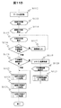
以下に、本実施例の共役波のホログラムを利用して得た演算中心を使った再生処理の手順を図16A、図16B、図17A、図17Bのフローチャートを用いて説明する。まず、図16A、図16Bのフローチャートに示したサイドバンド中央点(演算中央)を求めるサブルーチンについて説明する。このサブルーチンは、図17Aのサイドバンド中央(演算中央)の決定(S1705)に対応する。
図16Aにおいて、(1)複数のホログラムが記録されたデータをコンピュータに入力、表示する(S1601、S1602)。(2)入力画像データの内、参照ホログラムの領域のみを残し、他のデータを消去した画像データを作成する(S1603~S1609)。(3)この参照ホログラムのみデータにフーリエ変換を施し、リング状回折パターンを得る(S1610、S1611)。(4)得られたリング状回折パターンは、空間のみを透過し変調を受けないらせん波によるものであるので、理想的に完全な円形をしているはずである。(5)このリング状パターンを円形形状フィッティングすることによりリング中心、すなわち、サイドバンド中央(演算中央)の座標値(x、y)を数学的に求め、記録する(S1612~S1616)。この時の演算精度は、高いほど望ましいが、例えば、画素の1/10としサブ画素での処理とする。ここで求められたリング中心が、次に説明する本実施例の再生処理における演算原点となる(図17AのS1705)。
図17A、図17Bの処理フローにより、元ホログラムの再生処理を行う。(6)複数のホログラムが記録されたデータをコンピュータに入力する(S1701、S1702、上記の(1)の繰り返し)。(7)フーリエ変換を施したのち、上記の(5)で求めたリング中心を演算処理の原点として再生処理を継続する(S1706~S1708)。なお、S1709~S1725については、図13BのS1311~S1328と同じ処理であり説明を省略する。
本実施例においては、(8)直接波のホログラムについては直接波を、共役波のホログラムについては共役波を再生する。すなわち、一度に2つの再生波が得られている。(9)上記2つの再生波、特に位相分布(S1725)については、再生位相分布を比較参照することによって、物体がらせん波(直接波)に与えた位相変調を知ることができる。(10)得られた位相変調を、別途の知識により物理情報に置きなおし、らせん波による高精度物性計測を完了する。
先にも述べたように、らせん波では、リング状の回折波、あるいはデフォーカスを補正した図12の再生像についても、振幅分布の中央部の強度が極端に小さくなっており、位相を得られても実用的には利用することが困難な可能性もある。
そこで、実施例7では、位相分布の利用可能な範囲を明示するため、図18のA、Bの振幅分布と、図18のC、Dの位相分布についての合算像を利用することが合理的である。図18のE、Fに振幅分布と位相分布の合算像を示す。図18のE、Fに明らかなように、リングの上に渦状の位相分布像が重畳され、位相の値とともにその位相分布の得られる範囲が捻じれた紐の様に表示されている。
また、本実施例で述べたホログラムは、回折波の±1次と±2次とでは、干渉縞の縞間隔が2倍異なっている。そのため、4つのホログラムを同時に入力していても、フーリエ変換法では空間周波数フィルタリングが同時に実施されるため、各々個別に再生像をえることができる。そこで、入力ホログラム全体の再生像を得るためには、得られた再生像を合算することが必要になる。この例も図18のGとして示した。
以上詳述したレンズレス・フーリエ変換ホログラフィーと、本発明のホログラフィーの再生方法によれば、従来の電子線ホログラフィーでは実現できなかった電子らせん波と電子線ホログラフィーを合わせた手法が実現可能であり、多くの有効な情報を得ることが可能となる。
なお、上述した種々の実施例は本発明のより良い理解のために説明したのであり、必ずしも説明の全ての構成を備えるものに限定されものではない。また、ある実施例の構成の一部を他の実施例の構成に置き換えることが可能であり、また、ある実施例の構成に他の実施例の構成を加えることが可能である。また、各実施例の構成の一部について、他の構成の追加・削除・置換をすることが可能である。
更に、上述した各構成、機能、制御部等は、それらの一部又は全部を実現するプログラムが動作するシステム制御コンピュータを使用する例を説明したが、それらの一部又は全部を例えば集積回路で設計する等によりハードウェアで実現しても良いことは言うまでもない。すなわち、制御部の全部または一部の機能は、プログラムに代え、例えば、ASIC(Application Specific Integrated Circuit)、FPGA(Field Programmable Gate Array)などの集積回路などにより実現してもよい。
2、1902 光軸
3、1903 試料
16、1935 回折格子
21 透過波
22 回折波
25 入射粒子線
26 クロスオーバー、スポット
35 白い部分
36 サイドバンド
45 刃状転位格子
301 回折面
84 干渉縞
301 回折面
302 アンダーフォーカス面
303 オーバーフォーカス面
1901 電子銃もしくは粒子源
1904 荷電粒子線装置
1905 対物レンズ
1908 最終像
1938 回折格子の制御ユニット
1939 試料保持装置の制御ユニット
1940 加速管
1941 第1コンデンサレンズ
1942 第2コンデンサレンズ
1947 第2コンデンサレンズの制御ユニット
1948 第1コンデンサレンズの制御ユニット
1949 加速管の制御ユニット
1951 システム制御コンピュータ
1952 モニタ
1953 インターフェース
1959 対物レンズの制御ユニット
1961 第1結像レンズ
1962 第2結像レンズ
1963 第3結像レンズ
1964 第4結像レンズ
1966 第4結像レンズの制御ユニット
1967 第3結像レンズの制御ユニット
1968 第2結像レンズの制御ユニット
1969 第1結像レンズの制御ユニット
1975 像検出面
1976 画像データモニタ
1977 画像データ記録装置
1978 画像データコントローラ
1979 画像検出器
3、1903 試料
16、1935 回折格子
21 透過波
22 回折波
25 入射粒子線
26 クロスオーバー、スポット
35 白い部分
36 サイドバンド
45 刃状転位格子
301 回折面
84 干渉縞
301 回折面
302 アンダーフォーカス面
303 オーバーフォーカス面
1901 電子銃もしくは粒子源
1904 荷電粒子線装置
1905 対物レンズ
1908 最終像
1938 回折格子の制御ユニット
1939 試料保持装置の制御ユニット
1940 加速管
1941 第1コンデンサレンズ
1942 第2コンデンサレンズ
1947 第2コンデンサレンズの制御ユニット
1948 第1コンデンサレンズの制御ユニット
1949 加速管の制御ユニット
1951 システム制御コンピュータ
1952 モニタ
1953 インターフェース
1959 対物レンズの制御ユニット
1961 第1結像レンズ
1962 第2結像レンズ
1963 第3結像レンズ
1964 第4結像レンズ
1966 第4結像レンズの制御ユニット
1967 第3結像レンズの制御ユニット
1968 第2結像レンズの制御ユニット
1969 第1結像レンズの制御ユニット
1975 像検出面
1976 画像データモニタ
1977 画像データ記録装置
1978 画像データコントローラ
1979 画像検出器
Claims (15)
- 荷電粒子線装置よるホログラフィーの再生方法であって、
前記荷電粒子線装置は、荷電粒子線を照射する照射光学系と、照射される前記荷電粒子線の進行方向下流側に備えられ、前記荷電粒子線に対して透過性を有する材料からなる回折格子と、前記回折格子の回折面に試料を保持可能な試料保持部と、前記回折面を通過した前記荷電粒子線を結像する結像光学系と、前記結像光学系による結像を検出する画像検出部と、前記画像検出部が検出した画像データを処理する制御部と、を備え、
前記制御部は、
前記回折格子の開口領域を、前記荷電粒子線の前記回折格子への照射領域よりも小さくして、前記回折格子により回折された前記荷電粒子線の照射領域が、前記回折格子を透過した前記荷電粒子線の照射領域内にある状態とし、
前記画像データに基づき得られる複数のホログラムの少なくも一つを選択し、選択した前記ホログラムをフーリエ変換する、よう制御する、
ことを特徴とするホログラフィーの再生方法。 - 請求項1に記載のホログラフィーの再生方法であって、
前記回折格子により回折された前記荷電粒子線がらせん波である、
ことを特徴とするホログラフィーの再生方法。 - 請求項2に記載のホログラフィーの再生方法であって、
前記制御部は、
複数の前記ホログラムの一部を選択してフーリエ変換し、得られた強度分布像中の複数のサイドバンドの一つを選択し、
選択したサイドバンドをフーリエ逆変換し、得られる振幅分布像と位相分布像を表示する、よう制御する、
ことを特徴とするホログラフィーの再生方法。 - 請求項1に記載のホログラフィーの再生方法であって、
前記制御部は、
複数の前記ホログラムをフーリエ変換し、得られた強度分布像のサイドバンドの一つを選択し、
選択した前記サイドバンドをフーリエ逆変換し、
得られた振幅分布像と位相分布像を表示する、よう制御する、
ことを特徴とするホログラフィーの再生方法。 - 請求項4に記載のホログラフィーの再生方法であって、
前記回折格子により回折された前記荷電粒子線がらせん波である、
ことを特徴とするホログラフィーの再生方法。 - 請求項5に記載のホログラフィーの再生方法であって、
前記制御部は、
選択した前記サイドバンドの中央を決定し、
当該サイドバンドの中央点を演算原点に移動した後、前記フーリエ逆変換を行う、
ことを特徴とするホログラフィーの再生方法。 - 請求項6に記載のホログラフィーの再生方法であって、
前記制御部は、
演算原点に移動した前記サイドバンドに対し、フォーカス補正演算を行った後、前記フーリエ逆変換を行う、
ことを特徴とするホログラフィーの再生方法。 - 請求項6に記載のホログラフィーの再生方法であって、
前記制御部は、
前記らせん波である、回折された前記荷電粒子線の回折スポットの正負いずれか一方が、前記回折格子の回折面に設置される前記試料に照射されたスポットを処理する、
ことを特徴とするホログラフィーの再生方法。 - 請求項8に記載のホログラフィーの再生方法であって、
前記制御部は、
他方の前記回折スポットによる前記ホログラムをフーリエ変換して、前記サイドバンドの中央を決定する、
ことを特徴とするホログラフィーの再生方法。 - 請求項5に記載のホログラフィーの再生方法であって、
らせん波である、回折された前記荷電粒子線の回折スポットの複数の次数に対応する複数の再生像を合算して表示する
ことを特徴とするホログラフィーの再生方法。 - 荷電粒子線を照射する照射光学系と、照射される前記荷電粒子線の進行方向下流側に備えられ、前記荷電粒子線に対して透過性を有する材料からなる回折格子と、前記回折格子の回折面に試料を保持可能な試料保持部と、前記回折面を通過した前記荷電粒子線を結像する結像光学系と、前記結像光学系による結像を検出する画像検出部とを備える荷電粒子線装置で得られる画像データを処理する制御部で実行されるホログラフィーの再生プログラムであって、
前記制御部を、
前記回折格子の開口領域を、前記荷電粒子線の前記回折格子への照射領域よりも小さくして、前記回折格子により回折された前記荷電粒子線の照射領域が、前記回折格子を透過した前記荷電粒子線の照射領域内にある状態とし、
前記画像データに基づき得られる複数のホログラムの少なくも一つを選択し、選択した前記ホログラムをフーリエ変換する、よう制御する、
ホログラフィーの再生プログラム。 - 請求項11に記載のホログラフィーの再生プログラムであって、
前記回折格子により回折された前記荷電粒子線がらせん波であり、
前記制御部を、
複数の前記ホログラムをフーリエ変換し、得られた強度分布像のサイドバンドの一つを選択し、
選択した前記サイドバンドの中央を決定し、
当該サイドバンドの中央点を演算原点に移動した後、フーリエ逆変換を行う、よう制御する
ことを特徴とするホログラフィーの再生プログラム。 - 請求項12に記載のホログラフィーの再生プログラムであって、
前記制御部を、
演算原点に移動した前記サイドバンドに対し、フォーカス補正演算を行った後、前記フーリエ逆変換を行う、よう制御する
ことを特徴とするホログラフィーの再生プログラム。 - 請求項13に記載のホログラフィーの再生プログラムであって、
前記制御部を、
前記らせん波である、回折された前記荷電粒子線の回折スポットの正負いずれか一方を、前記回折格子の回折面に設置された前記試料に照射する、よう制御する、
ことを特徴とするホログラフィーの再生プログラム。 - 請求項14に記載のホログラフィーの再生プログラムであって、
前記制御部を、
他方の回折スポットによる前記ホログラムをフーリエ変換して、前記サイドバンドの中央を決定する、よう制御する、
ことを特徴とするホログラフィーの再生プログラム。
Priority Applications (1)
| Application Number | Priority Date | Filing Date | Title |
|---|---|---|---|
| US16/497,738 US11024482B2 (en) | 2017-04-28 | 2018-03-22 | Holography reconstruction method and program |
Applications Claiming Priority (2)
| Application Number | Priority Date | Filing Date | Title |
|---|---|---|---|
| JP2017090408A JP6844777B2 (ja) | 2017-04-28 | 2017-04-28 | ホログラフィー再生方法及びプログラム |
| JP2017-090408 | 2017-04-28 |
Publications (1)
| Publication Number | Publication Date |
|---|---|
| WO2018198613A1 true WO2018198613A1 (ja) | 2018-11-01 |
Family
ID=63920225
Family Applications (1)
| Application Number | Title | Priority Date | Filing Date |
|---|---|---|---|
| PCT/JP2018/011397 Ceased WO2018198613A1 (ja) | 2017-04-28 | 2018-03-22 | ホログラフィー再生方法及びプログラム |
Country Status (3)
| Country | Link |
|---|---|
| US (1) | US11024482B2 (ja) |
| JP (1) | JP6844777B2 (ja) |
| WO (1) | WO2018198613A1 (ja) |
Families Citing this family (7)
| Publication number | Priority date | Publication date | Assignee | Title |
|---|---|---|---|---|
| JP6844777B2 (ja) * | 2017-04-28 | 2021-03-17 | 国立研究開発法人理化学研究所 | ホログラフィー再生方法及びプログラム |
| KR102577707B1 (ko) * | 2018-04-30 | 2023-09-14 | 한국전자통신연구원 | 진폭 변조 홀로그램을 위한 홀로그램 인코딩 및 홀로그램 화질 평가 장치 및 그 방법 |
| KR102732451B1 (ko) * | 2019-04-01 | 2024-11-21 | 삼성전자주식회사 | 홀로그램 영상 데이터를 처리하는 장치 및 방법 |
| CN111445554B (zh) * | 2020-05-09 | 2022-09-23 | 南京大学 | 一种多会聚角混合扫描电子显微成像方法 |
| US12380638B2 (en) | 2020-07-14 | 2025-08-05 | National Institute Of Information And Communications Technology | Non-transitory storage medium storing thereon optical aberration correction program and non-transitory storage medium storing thereon optical wavefront estimation |
| JP7642524B2 (ja) * | 2021-12-24 | 2025-03-10 | 株式会社日立製作所 | 干渉走査透過型電子顕微鏡 |
| CN115144371B (zh) * | 2022-07-19 | 2025-05-02 | 南京理工大学 | 基于波长扫描的无透镜傅里叶叠层衍射层析显微成像方法 |
Citations (4)
| Publication number | Priority date | Publication date | Assignee | Title |
|---|---|---|---|---|
| US20130168577A1 (en) * | 2011-12-16 | 2013-07-04 | Consiglio Nazionale Delle Ricerche | Converter of orbital momentum into spin momentum for the polarization of particle beams |
| WO2014167884A1 (ja) * | 2013-04-12 | 2014-10-16 | 株式会社日立製作所 | 回折格子、または回折格子素子、またはそれらを備えた荷電粒子線装置 |
| WO2015118624A1 (ja) * | 2014-02-05 | 2015-08-13 | 株式会社日立製作所 | 荷電粒子線装置、光学装置、照射方法、回折格子システム、及び回折格子 |
| WO2017183472A1 (ja) * | 2016-04-19 | 2017-10-26 | 国立研究開発法人理化学研究所 | 粒子線装置、観察法、および回折格子 |
Family Cites Families (10)
| Publication number | Priority date | Publication date | Assignee | Title |
|---|---|---|---|---|
| EP0866943B1 (de) * | 1995-12-15 | 2001-07-04 | Fraunhofer-Gesellschaft Zur Förderung Der Angewandten Forschung E.V. | Verfahren und vorrichtung zur hochauflösenden bestimmung von abständen im fokussierten bild eines linsen-pupillen-systems |
| EP1452894A3 (en) * | 1996-09-02 | 2005-02-09 | Nippon Telegraph and Telephone Corporation | Optical signal processing apparatus and optical signal processing method |
| US6987911B2 (en) * | 2000-03-16 | 2006-01-17 | Lightsmyth Technologies, Inc. | Multimode planar waveguide spectral filter |
| US6879441B1 (en) * | 2000-03-16 | 2005-04-12 | Thomas Mossberg | Holographic spectral filter |
| DE10345898A1 (de) * | 2003-07-11 | 2005-01-27 | Tesa Scribos Gmbh | Verfahren zum Berechnen und zum Erzeugen eines computergenerierten Hologramms sowie ein Speichermedium mit einem computergenerierten Hologramm und eine Lesevorrichtung |
| JP4795974B2 (ja) * | 2004-01-27 | 2011-10-19 | ディスプレイテック,インコーポレイテッド | ホログラフィックデータストレージに使用するための書き込みヘッド |
| US20090052619A1 (en) | 2005-04-20 | 2009-02-26 | Hisamitsu Endoh | Fresnel zone plate and x-ray microscope using the fresnel zone plate |
| US8680488B2 (en) * | 2012-02-14 | 2014-03-25 | Benjamin McMorran | System and method for producing and using multiple electron beams with quantized orbital angular momentum in an electron microscope |
| JP6844777B2 (ja) * | 2017-04-28 | 2021-03-17 | 国立研究開発法人理化学研究所 | ホログラフィー再生方法及びプログラム |
| WO2019203876A2 (en) * | 2017-08-17 | 2019-10-24 | The Trustees Of Columbia University In The City Of New York | Systems and methods for controlling electromagnetic radiation |
-
2017
- 2017-04-28 JP JP2017090408A patent/JP6844777B2/ja not_active Expired - Fee Related
-
2018
- 2018-03-22 WO PCT/JP2018/011397 patent/WO2018198613A1/ja not_active Ceased
- 2018-03-22 US US16/497,738 patent/US11024482B2/en not_active Expired - Fee Related
Patent Citations (4)
| Publication number | Priority date | Publication date | Assignee | Title |
|---|---|---|---|---|
| US20130168577A1 (en) * | 2011-12-16 | 2013-07-04 | Consiglio Nazionale Delle Ricerche | Converter of orbital momentum into spin momentum for the polarization of particle beams |
| WO2014167884A1 (ja) * | 2013-04-12 | 2014-10-16 | 株式会社日立製作所 | 回折格子、または回折格子素子、またはそれらを備えた荷電粒子線装置 |
| WO2015118624A1 (ja) * | 2014-02-05 | 2015-08-13 | 株式会社日立製作所 | 荷電粒子線装置、光学装置、照射方法、回折格子システム、及び回折格子 |
| WO2017183472A1 (ja) * | 2016-04-19 | 2017-10-26 | 国立研究開発法人理化学研究所 | 粒子線装置、観察法、および回折格子 |
Non-Patent Citations (1)
| Title |
|---|
| J. VERBEECK ET AL.: "Production and application of electron vortex beams", NATURE, vol. 467, no. 7313, 16 September 2010 (2010-09-16), pages 301 - 304, XP055037887 * |
Also Published As
| Publication number | Publication date |
|---|---|
| JP6844777B2 (ja) | 2021-03-17 |
| US20200105498A1 (en) | 2020-04-02 |
| US11024482B2 (en) | 2021-06-01 |
| JP2018190550A (ja) | 2018-11-29 |
Similar Documents
| Publication | Publication Date | Title |
|---|---|---|
| JP6844777B2 (ja) | ホログラフィー再生方法及びプログラム | |
| JP7161777B2 (ja) | ホログラフィック撮像装置および同装置に用いるデータ処理方法 | |
| JP6424313B2 (ja) | ホログラフィック顕微鏡および高分解能ホログラム画像用のデータ処理方法 | |
| Bowman et al. | Efficient generation of Bessel beam arrays by means of an SLM | |
| EP2919061B1 (en) | Phase modulation method and phase modulating device | |
| JP6040469B2 (ja) | デジタルホログラフィ装置 | |
| US8946628B2 (en) | Electron beam interference device and electron beam interferometry | |
| Rosi et al. | Theoretical and practical aspects of the design and production of synthetic holograms for transmission electron microscopy | |
| JP5382695B2 (ja) | 電子線干渉装置、および電子線干渉顕微方法 | |
| JP6931931B2 (ja) | 粒子線装置、観察法、および回折格子 | |
| JP7244829B2 (ja) | 干渉電子顕微鏡 | |
| Ishii et al. | Soft-x-ray vortex beam detected by inline holography | |
| KR102502586B1 (ko) | 라이트필드 데이터 변환을 이용한 왜곡 없는 홀로그램 생성 방법 및 장치 | |
| Clark et al. | Symmetry-constrained electron vortex propagation | |
| CN107526278A (zh) | 一种基于衍射光栅的数字全息成像方法、系统 | |
| WO2014167884A1 (ja) | 回折格子、または回折格子素子、またはそれらを備えた荷電粒子線装置 | |
| Pozzi | Electron holography of long-range electromagnetic fields: A tutorial | |
| JPWO2012115042A1 (ja) | デジタルホログラフィ装置、及びデジタルホログラフィによる3次元像再生方法 | |
| Mudassar | A simplified holography based superresolution system | |
| WO2015118624A1 (ja) | 荷電粒子線装置、光学装置、照射方法、回折格子システム、及び回折格子 | |
| Brady et al. | Design and implementation of a snapshot ptychographic wavefront camera array | |
| JP2007121883A (ja) | 三次元像表示システムおよび三次元像表示方法 | |
| Keimpema et al. | Electron holography image simulation of nanoparticles | |
| WO2017022093A1 (ja) | 電子線干渉装置および電子線干渉方法 | |
| Cowley et al. | Principles and theory of electron holography |
Legal Events
| Date | Code | Title | Description |
|---|---|---|---|
| 121 | Ep: the epo has been informed by wipo that ep was designated in this application |
Ref document number: 18791449 Country of ref document: EP Kind code of ref document: A1 |
|
| NENP | Non-entry into the national phase |
Ref country code: DE |
|
| 122 | Ep: pct application non-entry in european phase |
Ref document number: 18791449 Country of ref document: EP Kind code of ref document: A1 |