WO2018198548A1 - 複合材の成形方法及び複合材の成形装置 - Google Patents
複合材の成形方法及び複合材の成形装置 Download PDFInfo
- Publication number
- WO2018198548A1 WO2018198548A1 PCT/JP2018/009033 JP2018009033W WO2018198548A1 WO 2018198548 A1 WO2018198548 A1 WO 2018198548A1 JP 2018009033 W JP2018009033 W JP 2018009033W WO 2018198548 A1 WO2018198548 A1 WO 2018198548A1
- Authority
- WO
- WIPO (PCT)
- Prior art keywords
- resin
- laminate
- composite material
- film
- molding
- Prior art date
- Legal status (The legal status is an assumption and is not a legal conclusion. Google has not performed a legal analysis and makes no representation as to the accuracy of the status listed.)
- Ceased
Links
Images



Classifications
-
- B—PERFORMING OPERATIONS; TRANSPORTING
- B29—WORKING OF PLASTICS; WORKING OF SUBSTANCES IN A PLASTIC STATE IN GENERAL
- B29C—SHAPING OR JOINING OF PLASTICS; SHAPING OF MATERIAL IN A PLASTIC STATE, NOT OTHERWISE PROVIDED FOR; AFTER-TREATMENT OF THE SHAPED PRODUCTS, e.g. REPAIRING
- B29C70/00—Shaping composites, i.e. plastics material comprising reinforcements, fillers or preformed parts, e.g. inserts
- B29C70/04—Shaping composites, i.e. plastics material comprising reinforcements, fillers or preformed parts, e.g. inserts comprising reinforcements only, e.g. self-reinforcing plastics
- B29C70/28—Shaping operations therefor
- B29C70/40—Shaping or impregnating by compression not applied
- B29C70/42—Shaping or impregnating by compression not applied for producing articles of definite length, i.e. discrete articles
- B29C70/44—Shaping or impregnating by compression not applied for producing articles of definite length, i.e. discrete articles using isostatic pressure, e.g. pressure difference-moulding, vacuum bag-moulding, autoclave-moulding or expanding rubber-moulding
- B29C70/443—Shaping or impregnating by compression not applied for producing articles of definite length, i.e. discrete articles using isostatic pressure, e.g. pressure difference-moulding, vacuum bag-moulding, autoclave-moulding or expanding rubber-moulding and impregnating by vacuum or injection
-
- B—PERFORMING OPERATIONS; TRANSPORTING
- B29—WORKING OF PLASTICS; WORKING OF SUBSTANCES IN A PLASTIC STATE IN GENERAL
- B29C—SHAPING OR JOINING OF PLASTICS; SHAPING OF MATERIAL IN A PLASTIC STATE, NOT OTHERWISE PROVIDED FOR; AFTER-TREATMENT OF THE SHAPED PRODUCTS, e.g. REPAIRING
- B29C43/00—Compression moulding, i.e. applying external pressure to flow the moulding material; Apparatus therefor
- B29C43/02—Compression moulding, i.e. applying external pressure to flow the moulding material; Apparatus therefor of articles of definite length, i.e. discrete articles
- B29C43/10—Isostatic pressing, i.e. using non-rigid pressure-exerting members against rigid parts or dies
- B29C43/12—Isostatic pressing, i.e. using non-rigid pressure-exerting members against rigid parts or dies using bags surrounding the moulding material or using membranes contacting the moulding material
-
- B—PERFORMING OPERATIONS; TRANSPORTING
- B29—WORKING OF PLASTICS; WORKING OF SUBSTANCES IN A PLASTIC STATE IN GENERAL
- B29C—SHAPING OR JOINING OF PLASTICS; SHAPING OF MATERIAL IN A PLASTIC STATE, NOT OTHERWISE PROVIDED FOR; AFTER-TREATMENT OF THE SHAPED PRODUCTS, e.g. REPAIRING
- B29C43/00—Compression moulding, i.e. applying external pressure to flow the moulding material; Apparatus therefor
- B29C43/32—Component parts, details or accessories; Auxiliary operations
-
- B—PERFORMING OPERATIONS; TRANSPORTING
- B29—WORKING OF PLASTICS; WORKING OF SUBSTANCES IN A PLASTIC STATE IN GENERAL
- B29C—SHAPING OR JOINING OF PLASTICS; SHAPING OF MATERIAL IN A PLASTIC STATE, NOT OTHERWISE PROVIDED FOR; AFTER-TREATMENT OF THE SHAPED PRODUCTS, e.g. REPAIRING
- B29C70/00—Shaping composites, i.e. plastics material comprising reinforcements, fillers or preformed parts, e.g. inserts
- B29C70/04—Shaping composites, i.e. plastics material comprising reinforcements, fillers or preformed parts, e.g. inserts comprising reinforcements only, e.g. self-reinforcing plastics
- B29C70/28—Shaping operations therefor
- B29C70/30—Shaping by lay-up, i.e. applying fibres, tape or broadsheet on a mould, former or core; Shaping by spray-up, i.e. spraying of fibres on a mould, former or core
- B29C70/34—Shaping by lay-up, i.e. applying fibres, tape or broadsheet on a mould, former or core; Shaping by spray-up, i.e. spraying of fibres on a mould, former or core and shaping or impregnating by compression, i.e. combined with compressing after the lay-up operation
- B29C70/345—Shaping by lay-up, i.e. applying fibres, tape or broadsheet on a mould, former or core; Shaping by spray-up, i.e. spraying of fibres on a mould, former or core and shaping or impregnating by compression, i.e. combined with compressing after the lay-up operation using matched moulds
Definitions
- the present invention relates to a composite material forming method and a composite material forming apparatus.
- a reinforcing fiber base material laminated on a mold is air-tightly covered with a vacuum film and vacuum sucked, and then a resin material is injected, impregnated, and cured to form a composite material.
- VaRTM molding is known (for example, see Patent Document 1).
- the deaeration part is arrange
- a plurality of resin supply portions are arranged on the molded body on both sides of the deaeration portion.
- the deaeration part is a deaeration bag having a cloth having a semi-permeable membrane (semi-permeable membrane) and a ventilation means, and allows passage of a gas such as air while passing resin. Is impossible.
- the impregnation rate of the resin is slower in the plate thickness direction than the in-plane direction orthogonal to the plate thickness direction (stacking direction) of the to-be-molded body.
- the resin supplied from both sides flows toward the deaeration part, There is a possibility that the deaeration part is covered with resin. If the deaeration part is covered with the resin, it becomes difficult to suck air, so that the deaeration becomes insufficient on the side of the molding die opposite to the deaeration part of the molded body. Unimpregnated regions can be formed.
- the molded body is degassed and the resin is discharged, thereby adjusting the injection amount of the resin. That is, in this molding method, the degassing line and the resin discharging line are the same line.
- the resin thickness changes from a portion where the plate thickness is thin due to the difference in resin impregnation speed in the plate thickness direction and in-plane direction. By moving forward toward the thick part, there is a possibility that an unimpregnated region of the resin is formed in the thick part.
- the present invention can suitably form a composite material by suppressing the formation of an unimpregnated region even when the thickness of the composite material changes in one direction within the surface of the composite material. It is an object of the present invention to provide a composite material molding method and composite material molding apparatus.
- the composite material molding method of the present invention is a composite material molding method for molding a composite material in which reinforcing fiber base materials are laminated, on the molding surface of a molding jig for molding the composite material, A laminated body in which the reinforcing fiber base material is laminated is disposed, the laminated body is covered with a film and hermetically sealed, and from the resin supply unit provided on the film side of the laminated body, toward the laminated body
- the resin in the film is supplied from a deaeration waterproofing portion provided on the molding surface side of the laminate and extending in one direction in a plane orthogonal to the lamination direction of the laminate.
- the atmosphere in the film is sucked so that the laminate is impregnated with the resin, and after impregnation of the resin into the laminate, the resin discharged on the film side of the laminate is discharged.
- the resin in the film is discharged from the section And features.
- the composite material molding apparatus of the present invention is a composite material molding device for molding a composite material in which reinforcing fiber base materials are laminated, and has a molding surface for molding the composite material, and the reinforcing fiber
- sucks the atmosphere of this, and the resin discharge part which is provided in the said film side of the said laminated body, and discharges the resin in the said film is characterized by the above-mentioned.
- the laminate is characterized in that the thickness in the laminating direction is changed over the one direction in a plane orthogonal to the laminating direction.
- the resin can be supplied from the film side of the laminate, and the atmosphere in the film can be sucked from the molding surface side of the laminate.
- the resin is suitably impregnated also in the laminating direction where the impregnation speed is slow.
- the deaeration waterproof part is provided in one direction of the laminate, in the composite material in which the plate thickness changes in one direction, the impregnation of the thin part where the thickness of the laminate is thin is completed.
- the resin supply unit is preferably a resin diffusion supply unit that diffuses and supplies the resin in the one direction of the laminate.
- the resin can be diffused and supplied in one direction of the laminate, the resin can be supplied in one direction in which the plate thickness changes. For this reason, by diffusing the resin from the film side of the laminate, it is possible to suppress the formation of an unimpregnated region due to a change in plate thickness.
- the deaeration waterproof part is provided on the downstream side in the circulation direction of the atmosphere, and a ventilation waterproof film that allows passage of the atmosphere in the film while blocking passage of the resin in the film. It is preferable to have a vacuum suction medium through which the atmosphere that has passed through the waterproof waterproof membrane circulates, and a vacuum suction line connected to the vacuum suction medium.
- the atmosphere in the film can be sucked from the vacuum suction line through the vacuum suction medium and the ventilation waterproof film.
- the deaeration waterproof part further includes a vacuum gauge that is provided on one of the vacuum suction medium and the vacuum suction line and measures a degree of vacuum.
- the degree of vacuum in the film can be measured by the vacuum gauge.
- the resin discharge unit also serves as the resin supply unit.
- the deaeration waterproof part is provided in a non-use area where the composite material after molding is not used as a product.
- the deaeration waterproof part is provided on the molding surface side of the laminate, it is possible to suppress the influence that the molding surface of the product is poorly formed by providing it in the unused area.
- the unused area is, for example, an area that is cut during processing.
- the resin supply unit is provided on one side of the orthogonal direction, and the deaeration waterproof unit is the orthogonal direction It is preferable to be provided on the other side.
- the laminate can be suitably impregnated with the resin.
- the resin supply unit is provided in the center of the orthogonal direction, and the deaeration waterproof unit is arranged in the orthogonal direction. It is preferable to be provided on both sides.
- the laminate can be suitably impregnated with the resin.
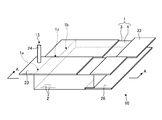
- FIG. 1 is a schematic configuration diagram illustrating a part of a molding apparatus for a composite material according to a first embodiment.
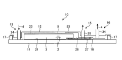
- FIG. 2 is a cross-sectional view schematically illustrating the composite material forming apparatus according to the first embodiment.
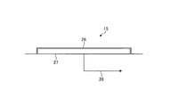
- FIG. 3 is a schematic diagram illustrating an example of a deaeration waterproofing unit.
- FIG. 4 is a schematic diagram illustrating an example of the deaeration waterproofing unit.
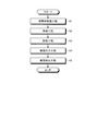
- FIG. 5 is a flowchart relating to a method for forming a composite material according to the first embodiment.
- FIG. 6 is a schematic configuration diagram illustrating a part of the composite material forming apparatus according to the second embodiment.
- FIG. 7 is a schematic diagram illustrating an example of a deaeration waterproof unit of the composite material molding apparatus according to the third embodiment.
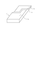
- FIG. 8 is a perspective view schematically showing an example of a composite material.
- the molding apparatus and the molding method of the composite material 1 according to the first embodiment are, for example, apparatuses for molding a structure constituting an aircraft body or the like.
- the structure includes a wing body such as a main wing, a horizontal wing or a tail wing, and an airframe.
- the structure is not particularly limited, and the composite material 1 will be described.
- FIG. 1 is a schematic configuration diagram showing a part of a composite material forming apparatus according to the first embodiment.
- FIG. 2 is a cross-sectional view schematically showing the composite material forming apparatus according to the first embodiment, and is a cross-sectional view taken along the line AA of FIG.
- FIG. 3 is a schematic diagram illustrating an example of a deaeration waterproofing unit.
- FIG. 4 is a schematic diagram illustrating an example of the deaeration waterproofing unit.
- FIG. 5 is a flowchart relating to a method for forming a composite material according to the first embodiment.
- the composite material 1 molded in Embodiment 1 is configured using, for example, carbon fiber reinforced plastic (CFRP: Carbon Fiber Reinforced Plastic).
- CFRP Carbon Fiber Reinforced Plastic
- This composite material 1 is formed by laminating a sheet-like reinforcing fiber base material 2 to form a laminate 3, and then molding the laminate 3 by impregnating the resin 4 with a resin 4 and curing the laminate 3.
- Transfer Molding Vacuum impregnation method
- the composite material 1 has a plate thickness in the stacking direction that changes in a predetermined in-plane direction (one direction) in a plane orthogonal to the stacking direction of the reinforcing fiber base 2. ing.
- the composite material 1 includes, in one direction, a thick part 1a that is a thick part, a thin part 1b that is a thin part, and a thick part 1a and a thin part 1b. It is molded including a step portion 1c that becomes a portion where the plate thickness changes.
- the longitudinal direction in which the composite material 1 extends is defined as one direction
- the direction orthogonal to the longitudinal direction and the stacking direction is defined as the width direction (orthogonal direction).
- FIG. 8 is a perspective view schematically showing an example of a composite material.
- board thickness of the composite material 1 is changing over the longitudinal direction and the width direction.
- the thick portion 1a is a part formed close to one side in the longitudinal direction (lower side in FIG. 8) and a part formed close to the other side in the width direction (right side in FIG. 8). It is formed in an L shape in plan view.
- the thin-walled portion 1b is a plan view of a part formed close to the other side in the longitudinal direction (upper side in FIG. 8) and a part formed close to one side in the width direction (left side in FIG. 8). It is formed in an L shape and has a shape complementary to the thick part 1a.
- the step portion 1c is formed between the thick portion 1a and the thin portion 1b, and includes a portion where the plate thickness changes in the longitudinal direction and a portion where the plate thickness changes in the width direction. In the following description, the description is applied to the composite material 1 shown in FIG.
- a molding apparatus 10 for molding the composite material 1 includes a molding jig 11, a bagging film (film) 12, a resin supply unit 13, a deaeration waterproof unit 15, And a resin discharge part 16.
- a peel ply 5 that is peeled off to activate the surface of the laminate 3 may be disposed on the surface layer on the upper surface side of the laminate 3.
- the bagging film 12 covers the laminate 3 arranged on the molding surface 21 of the molding jig 11 and is provided with a sealing material 17 between the molding jig 11 so that the inside thereof is hermetically sealed. is doing.
- Resin supply unit 13 supplies resin 4 to laminate 3.
- the resin supply unit 13 is provided on the bagging film 12 side of the laminate 3 and is provided on one side in the width direction of the laminate 3 (left side in FIGS. 1 and 2).
- the resin supply unit 13 includes a resin diffusion medium 23 and a resin supply line 24.
- Resin diffusion media 23 is provided inside the bagging film 12 and disposed on the upper surface of the laminate 3. Further, the resin diffusion media 23 does not extend to the other end of the laminated body 3, is provided close to one side in the width direction of the laminated body 3, and is disposed over the longitudinal direction of the laminated body 3. .
- the resin diffusion medium 23 for example, a mesh, a nonwoven fabric, or the like is used.
- One end of the resin supply line 24 is connected to the resin diffusion medium 23 and is provided across the bagging film 12.
- the resin supply line 24 supplies the resin 4 from the outside of the bagging film 12 toward the resin diffusion media 23 in the bagging film 12.
- the resin supply line 24 is provided with an on-off valve (not shown). The resin is supplied by opening the on-off valve, while the resin supply is stopped by closing the on-off valve.
- the resin supply unit 13 supplies the resin 4 from the resin supply line 24 toward the resin diffusion media 23, the resin diffusion media 23 diffuses the resin 4 in the longitudinal direction of the laminate 3, Resin 4 is supplied from one side in the width direction on the upper surface.
- the resin supply unit 13 functions as a resin diffusion supply unit that diffuses and supplies the resin 4 in the longitudinal direction of the laminate 3.
- the resin diffusion media 23 are not extended to the other end portion of the multilayer body 3, it is possible to prevent the resin from going to the other side (suction side) of the multilayer body 3.
- the deaeration waterproof part 15 sucks the atmosphere in the bagging film 12 while blocking the inflow of the resin 4.
- the deaeration waterproof part 15 is provided between the laminated body 3 and the molding jig 11, that is, on the lower surface (molding surface 21) side of the laminated body 3, and the other side in the width direction of the laminated body 3 (FIG. 1 and FIG. It is provided on the right side of FIG.
- the other side in the width direction of the laminate 3 is a non-use area in which the molded composite material 1 is not used as a product, and the deaeration waterproof part 15 is provided in this non-use area.
- Examples of the non-use area include an area that is cut during processing.
- the deaeration waterproof unit 15 includes a ventilation waterproof film 26, a vacuum suction medium 27, and a vacuum suction line 28.
- FIG.3 and FIG.4 is illustrated.
- the breathable waterproof film 26 has semi-permeability and allows passage of the atmosphere in the bagging film 12 while blocking the passage of the resin 4 in the bagging film 12.
- Gore-Tex (registered trademark) Etc. are used.
- the ventilation waterproof film 26 is provided inside the bagging film 12 and is provided on the uppermost stream side in the circulation direction of the atmosphere in the bagging film 12.
- the vacuum suction medium 27 is provided inside the bagging film 12, and is provided downstream of the ventilation waterproof film 26 in the direction of circulation of the atmosphere. That is, the vacuum suction medium 27 is provided between the ventilation waterproof film 26 and the molding jig 11.
- the vacuum suction medium 27 for example, a mesh, a nonwoven fabric, a groove, a duct, or the like is applied.
- FIG. 3 shows a case where a sheet-like member such as a mesh or a nonwoven fabric is applied as the vacuum suction medium 27.
- the deaeration waterproof unit 15 shown in FIG. 3 is provided so that the ventilation waterproof film 26 covers the vacuum suction medium 27 when the vacuum suction medium 27 is a sheet-like member.
- FIG. 4 shows a case where a duct is applied as the vacuum suction medium 27.
- the deaeration waterproof unit 15 shown in FIG. 4 is provided so that the ventilation waterproof film 26 covers the opening of the vacuum suction medium 27 when the vacuum suction medium 27 is a duct.
- the air permeable waterproof film 26 and the vacuum suction medium 27 are provided close to the other side in the width direction of the laminated body 3 and are arranged in the longitudinal direction of the laminated body 3.
- the vacuum suction line 28 sucks the atmosphere in the bagging film 12 through the vacuum suction medium 27.
- the vacuum suction line 28 is provided over the inside and outside of the bagging film 12, but the vacuum suction line 28 may be provided inside the forming jig 11, and the arrangement is not particularly limited.
- the vacuum suction line 28 is provided with an opening / closing valve (not shown). The opening of the opening / closing valve sucks the atmosphere, and the opening / closing valve closes the atmosphere suction.
- the degassing waterproof unit 15 When the degassing waterproof unit 15 sucks the atmosphere in the bagging film 12 from the vacuum suction line 28 via the vacuum suction medium 27, the vacuum suction medium 27 moves the atmosphere from the other side in the width direction of the laminate 3. By sucking in the longitudinal direction, the bagging film 12 is degassed.
- the deaeration waterproof part 15 blocks the inflow of the resin 4 by the ventilation waterproof film 26, and therefore suppresses the inflow of the resin 4 to the vacuum suction medium 27 and the vacuum suction line 28.
- the ventilation waterproofing film 26 is covered with the resin 4
- the deaeration waterproof unit 15 blocks the circulation of the atmosphere. For this reason, the deaeration waterproof part 15 also stops the suction of the atmosphere when the breathable waterproof film 26 is covered with the resin 4.
- the resin discharge unit 16 discharges the resin 4 supplied to the laminate 3.
- the resin discharger 16 is provided on the bagging film 12 side of the laminate 3 and is provided on the other side in the width direction of the laminate 3 (right side in FIGS. 1 and 2). For this reason, the resin discharge part 16 is provided on the same side as the deaeration waterproof part 15 in the width direction, and is provided in a position facing the deaeration waterproof part 15 with the laminate 3 interposed therebetween in the stacking direction.
- the resin discharge unit 16 includes a resin discharge medium 33 and a resin discharge line 34.
- the resin discharge medium 33 is provided inside the bagging film 12 and disposed on the upper surface of the laminate 3. Further, the resin discharge medium 33 is provided close to the other side in the width direction of the multilayer body 3 and is disposed over the longitudinal direction of the multilayer body 3.
- the resin discharge medium 33 for example, a mesh, a nonwoven fabric, or the like is used.
- the resin discharge line 34 is connected to the resin discharge medium 33 and is provided across the bagging film 12.
- the resin discharge line 34 discharges the resin 4 in the bagging film 12 through the resin discharge medium 33.
- the resin discharge line 34 is provided with an open / close valve (not shown), and the resin is discharged by opening the open / close valve, while the resin discharge is stopped by closing the open / close valve.
- the resin discharge unit 16 discharges the resin 4 from the resin discharge line 34 through the resin discharge medium 33
- the resin discharge medium 33 discharges the resin 4 over the longitudinal direction of the stacked body 3 and the stacked body.
- the resin 4 is discharged from the other side in the width direction on the upper surface of 3.
- the molding jig 11 of the molding apparatus 10 is preliminarily provided with a ventilation waterproof film 26 and a vacuum suction medium 27 of the deaeration waterproof part 15.
- the reinforcing fiber base material 2 is laminated
- positioning process S1 the reinforced fiber base material 2 is laminated
- the laminated body 3 is arranged so that the deaeration waterproof part 15 is located between the other side in the width direction of the laminated body 3 and the forming jig 11.
- step S2 preparation process
- the laminate 3 is covered with the bagging film 12, and the sealing material 17 is disposed between the bagging film 12 and the molding jig 11 on the outside of the bagging film 12 to be hermetically sealed.
- the resin supply unit 13 is disposed on one side in the width direction, and the resin discharge unit 16 is disposed on the other side in the width direction.
- step S3 deaeration step
- the open / close valves provided in the resin supply line 24 and the resin discharge line 34 are closed, and the open / close valves provided in the vacuum suction line 28 are opened, whereby the laminated body Perform 3 deaeration.
- step S4 resin injection step. Specifically, in the resin injection step S4, the open / close valve provided in the resin discharge line 34 is closed, and the open / close valves provided in the resin supply line 24 and the vacuum suction line 28 are opened, so that the laminated body The resin 4 is supplied to 3.
- the resin injection step S4 when the resin 4 is injected into the laminated body 3, the resin 4 is impregnated in the in-plane direction and the laminating direction on the upper surface of the laminated body 3.
- the impregnation rate of the resin 4 in the laminating direction is slower than the impregnation rate of the resin 4 in the in-plane direction, the resin 4 is easy to spread in the in-plane direction and difficult to impregnate in the laminating direction.
- the resin 4 impregnated in the laminating direction has a faster impregnation of the thin portion 1b than the thick portion 1a of the laminate 3, the resin 4 reaches the molding surface 21 in the thin portion 1b.
- the resin 4 that has reached the molding surface 21 covers the ventilation waterproof film 26 of the deaeration waterproof part 15 from the thin part 1 b side to the thick part 1 a side in the longitudinal direction of the laminate 3. Then, when the resin 4 covers the entire surface of the ventilation waterproof film 26 of the deaeration waterproof part 15, the suction of the atmosphere in the bagging film 12 is stopped.
- step S5 resin discharge step
- the open / close valves provided in the resin discharge line 34 and the vacuum suction line 28 are opened, and the open / close valves provided in the resin supply line 24 are closed, so that the laminated body 3 is discharged.
- the on-off valve provided in the vacuum suction line 28 is in the open state, as described above, since the entire surface of the ventilation waterproof film 26 of the deaeration waterproof part 15 is covered with the resin 4, the atmosphere in the bagging film 12 is reduced. No suction is performed.
- the open / close valve provided in the vacuum suction line 28 may be closed.
- the laminate 3 impregnated with the resin 4 shifts to a thermosetting process.
- the resin 4 can be supplied from the bagging film 12 side of the laminate 3 and the atmosphere in the bagging film 12 can be sucked from the molding surface 21 side of the laminate 3. At this time, since the atmosphere in the bagging film 12 is sucked from the bagging film 12 side to the molding surface 21 side, the resin 4 is suitably impregnated also in the laminating direction where the impregnation speed is slow.
- the deaeration waterproof part 15 is provided over one direction of the laminated body 3, the impregnation of the thin part 1b is complete
- the resin 4 in the bagging film 12 can be discharged from the resin discharge portion 16 provided on the bagging film 12 side of the laminate 3. Therefore, the injection amount of the resin 4 can be adjusted so that the plate thickness or fiber content required for the composite material 1 is obtained.
- the resin supply part 13 can supply the resin 4 by diffusing in the longitudinal direction of the laminated body 3, it can supply the resin 4 over the longitudinal direction where board thickness changes. . For this reason, by diffusing the resin 4 from the bagging film 12 side of the laminate 3, it is possible to suppress the formation of the unimpregnated region due to the change in the plate thickness.
- the atmosphere in the bagging film 12 can be sucked from the vacuum suction line 28 through the vacuum suction medium 27 and the ventilation waterproof film 26 in the deaeration waterproof unit 15.
- the deaeration waterproof part 15 is provided in the molding surface 21 side of the laminated body 3, it has the influence that the molding surface 21 of a product becomes poor formation by providing in a non-use area
- the bagging film 12 is supplied from the other side in the width direction of the laminate 3 in the deaeration waterproofing unit 15 while the resin 4 is supplied from the one side in the width direction of the laminate 3 in the resin supply unit 13. Since the inner atmosphere can be sucked, the laminate 3 can be suitably impregnated with the resin 4.
- the resin diffusion media 23 is not extended to the other end portion of the laminate 3, and therefore, on the other side in the width direction of the laminate 3, the molding surface is formed from the bagging film 12 side. Since it is possible to prevent the resin 4 from moving forward to the 21 side, the impregnation of the resin 4 into the laminate 3 can be suitably performed.
- the resin supply unit 13 and the resin discharge unit 16 are provided as independent systems, but the resin supply unit 13 and the resin discharge unit 16 may be combined. According to this configuration, by combining the resin supply unit 13 and the resin discharge unit 16, the configuration of the apparatus can be simplified, and an increase in apparatus cost can be suppressed.
- FIG. 6 is a schematic configuration diagram illustrating a part of the composite material forming apparatus according to the second embodiment.
- the molding apparatus 10 according to the second embodiment is obtained by changing the arrangement of the resin supply unit 13 and the deaeration waterproof unit 15 of the first embodiment.
- the resin supply unit 13 is provided on the bagging film 12 side of the laminate 3 and at the center in the width direction of the laminate 3. For this reason, when the resin supply unit 13 supplies the resin 4 from the resin supply line 24 toward the resin diffusion medium 23, the resin diffusion medium 23 diffuses the resin 4 in the longitudinal direction of the laminate 3, while the laminate 3.
- the resin 4 is supplied from the center in the width direction on the upper surface of the substrate.
- the deaeration waterproof unit 15 is provided between the laminate 3 and the molding jig 11, that is, on the lower surface (molding surface 21) side of the laminate 3. A pair is provided on both sides in the width direction. For this reason, when the deaeration waterproof unit 15 sucks the atmosphere in the bagging film 12 from the vacuum suction line 28 via the vacuum suction medium 27, the vacuum suction medium 27 removes the atmosphere from both sides in the width direction of the laminate 3. By sucking in the longitudinal direction, the bagging film 12 is degassed.
- the resin supply unit 13 supplies the resin 4 from the center in the width direction of the laminate 3, while the degassing waterproof unit 15 provides the bagging film from both sides in the width direction of the laminate 3. Since the atmosphere in 12 can be sucked, the laminate 4 can be preferably impregnated with the resin 4.
- FIG. 7 is a schematic diagram illustrating an example of a deaeration waterproof unit of the composite material molding apparatus according to the third embodiment.
- the molding apparatus 10 according to the third embodiment is a device in which a vacuum gauge 41 is disposed in the deaeration waterproof unit 15 of the first embodiment.
- the vacuum gauge 41 is, for example, a vacuum gauge 41a (solid line) provided in the vacuum suction line 28 of the deaeration waterproofing unit 15 and the degree of vacuum in the vacuum suction line 28. Is measured.
- the vacuum gauge 41 may be the vacuum gauge 41b (dotted line) provided in the vacuum suction medium 27 of the deaeration waterproof part 15 as an example, and measures the vacuum degree in the vacuum suction medium 27.
- the vacuum gauge 41b is provided in the vacuum suction medium 27, the vacuum gauge 41b is provided at the position of the vacuum suction medium 27 corresponding to the part (for example, the thick portion 1a) where the impregnation of the resin 4 into the laminate 3 is the slowest. preferable.
- the vacuum degree in the bagging film 12 can be measured by the vacuum gauge 41.
- the arrangement relationship between the resin supply unit 13 and the deaeration waterproof unit 15 shown in FIGS. 1 and 6 is not particularly limited, and the deaeration waterproof unit 15 is arranged on the molding surface 21 side and the length of the laminate 3 It suffices if it is provided over the direction and the laminate 4 can be suitably impregnated with the resin 4. For this reason, as an example, while providing the resin supply part 13 in the bagging film 12 side of the laminated body 3 and providing it on both sides of the laminated body 3 in the width direction, the deaeration waterproof part 15 is provided on the molding surface 21 side of the laminated body 3. And may be provided at the center in the width direction of the laminate 3.
Landscapes
- Engineering & Computer Science (AREA)
- Mechanical Engineering (AREA)
- Chemical & Material Sciences (AREA)
- Composite Materials (AREA)
- Casting Or Compression Moulding Of Plastics Or The Like (AREA)
- Moulding By Coating Moulds (AREA)
Abstract
Description
実施形態1に係る複合材1の成形装置及び成形方法は、例えば、航空機の機体等を構成する構造体を成形するための装置である。構造体としては、主翼、水平翼または尾翼等の翼体、及び機体等がある。なお、実施形態1では、特に構造体を限定せず、単に複合材1として説明する。
次に、図6を参照して、実施形態2に係る複合材1の成形装置10について説明する。なお、実施形態2では、重複した記載を避けるべく、実施形態1と異なる部分について説明し、実施形態1と同様の構成である部分については、同じ符号を付して説明する。図6は、実施形態2に係る複合材の成形装置の一部を示す概略構成図である。
次に、図7を参照して、実施形態3に係る複合材1の成形装置10について説明する。なお、実施形態3でも、重複した記載を避けるべく、実施形態1及び2と異なる部分について説明し、実施形態1及び2と同様の構成である部分については、同じ符号を付して説明する。図7は、実施形態3に係る複合材の成形装置の脱気防水部の一例を示す模式図である。
1a 厚肉部
1b 薄肉部
1c 段部
2 強化繊維基材
3 積層体
4 樹脂
5 ピールプライ
10 成形装置
11 成形用治具
12 バギングフィルム
13 樹脂供給部
15 脱気防水部
16 樹脂排出部
17 シール材
18 シールテープ
21 成形面
23 樹脂拡散メディア
24 樹脂供給ライン
26 通気防水膜
27 真空吸引メディア
28 真空吸引ライン
33 樹脂排出メディア
34 樹脂排出ライン
41 真空計
41a 真空計
41b 真空計
Claims (10)
- 強化繊維基材が積層されてなる複合材を成形する複合材の成形方法であって、
前記複合材を成形するための成形用治具の成形面に、前記強化繊維基材が積層された積層体を配置し、
前記積層体をフィルムで覆って気密に封止し、
前記積層体の前記フィルム側に設けられた樹脂供給部から、前記積層体へ向けて樹脂を供給し、
前記積層体の前記成形面側に設けられると共に前記積層体の積層方向に直交する面内の一方向に亘って設けられた脱気防水部から、前記フィルム内の樹脂の通過を遮断しつつ、前記フィルム内の雰囲気を吸引して、前記積層体に前記樹脂を含浸させ、
前記積層体への前記樹脂の含浸後、前記積層体の前記フィルム側に設けられた樹脂排出部から、前記フィルム内の樹脂を排出させることを特徴とする複合材の成形方法。 - 前記積層体は、前記積層方向に直交する面内の前記一方向に亘って前記積層方向の板厚が変化していることを特徴とする請求項1に記載の複合材の成形方法。
- 強化繊維基材が積層されてなる複合材を成形する複合材の成形装置であって、
前記複合材を成形する成形面を有し、前記強化繊維基材が積層された積層体が配置される成形用治具と、
前記積層体を覆って気密に封止するフィルムと、
前記積層体の前記フィルム側に設けられ、樹脂を供給する樹脂供給部と、
前記積層体の前記成形面側に設けられると共に前記積層体の積層方向に直交する面内の一方向に亘って設けられ、前記フィルム内の前記樹脂の通過を遮断しつつ、前記フィルム内の雰囲気を吸引する脱気防水部と、
前記積層体の前記フィルム側に設けられ、前記フィルム内の樹脂を排出する樹脂排出部と、を備えることを特徴とする複合材の成形装置。 - 前記樹脂供給部は、前記樹脂を前記積層体の前記一方向に拡散して供給する樹脂拡散供給部であることを特徴とする請求項3に記載の複合材の成形装置。
- 前記脱気防水部は、
前記フィルム内の前記雰囲気の通過を許容する一方で、前記フィルム内の前記樹脂の通過を遮断する通気防水膜と、
前記雰囲気の流通方向の下流側に設けられ、前記通気防水膜を通過した前記雰囲気が流通する真空吸引メディアと、
前記真空吸引メディアに接続された真空吸引ラインと、を有することを特徴とする請求項3または4に記載の複合材の成形装置。 - 前記脱気防水部は、
前記真空吸引メディア及び前記真空吸引ラインの一方に設けられ、真空度を計測する真空計を、さらに有することを特徴とする請求項5に記載の複合材の成形装置。 - 前記樹脂排出部は、前記樹脂供給部を兼ねていることを特徴とする請求項3から6のいずれか1項に記載の複合材の成形装置。
- 前記脱気防水部は、成形後の前記複合材が製品として利用されない領域である不使用領域に設けられることを特徴とする請求項3から7のいずれか1項に記載の複合材の成形装置。
- 前記積層体の前記面内において、前記一方向に直交する方向を直交方向とすると、
前記樹脂供給部は、前記直交方向の一方側に設けられ、
前記脱気防水部は、前記直交方向の他方側に設けられることを特徴とする請求項3から8のいずれか1項に記載の複合材の成形装置。 - 前記積層体の前記面内において、前記一方向に直交する方向を直交方向とすると、
前記樹脂供給部は、前記直交方向の中央に設けられ、
前記脱気防水部は、前記直交方向の両側に設けられることを特徴とする請求項3から8のいずれか1項に記載の複合材の成形装置。
Priority Applications (3)
| Application Number | Priority Date | Filing Date | Title |
|---|---|---|---|
| BR112019022454-8A BR112019022454B1 (pt) | 2017-04-28 | 2018-03-08 | Método para moldagem de material compósito e dispositivo para moldagem de material compósito |
| CA3061458A CA3061458C (en) | 2017-04-28 | 2018-03-08 | Composite material molding method and composite material molding device |
| US16/607,294 US11498289B2 (en) | 2017-04-28 | 2018-03-08 | Composite material molding method and composite material molding device |
Applications Claiming Priority (2)
| Application Number | Priority Date | Filing Date | Title |
|---|---|---|---|
| JP2017090328A JP7085803B2 (ja) | 2017-04-28 | 2017-04-28 | 複合材の成形方法及び複合材の成形装置 |
| JP2017-090328 | 2017-04-28 |
Publications (1)
| Publication Number | Publication Date |
|---|---|
| WO2018198548A1 true WO2018198548A1 (ja) | 2018-11-01 |
Family
ID=63918294
Family Applications (1)
| Application Number | Title | Priority Date | Filing Date |
|---|---|---|---|
| PCT/JP2018/009033 Ceased WO2018198548A1 (ja) | 2017-04-28 | 2018-03-08 | 複合材の成形方法及び複合材の成形装置 |
Country Status (5)
| Country | Link |
|---|---|
| US (1) | US11498289B2 (ja) |
| JP (1) | JP7085803B2 (ja) |
| BR (1) | BR112019022454B1 (ja) |
| CA (1) | CA3061458C (ja) |
| WO (1) | WO2018198548A1 (ja) |
Citations (2)
| Publication number | Priority date | Publication date | Assignee | Title |
|---|---|---|---|---|
| JP2013154494A (ja) * | 2012-01-27 | 2013-08-15 | Yashima Co Ltd | 真空成形法およびそれによって成形された繊維強化樹脂製品 |
| JP2016151007A (ja) * | 2015-02-19 | 2016-08-22 | 三菱航空機株式会社 | 繊維基材を積層する方法、繊維基材群ロールの製造方法、繊維基材群、および航空機 |
Family Cites Families (6)
| Publication number | Priority date | Publication date | Assignee | Title |
|---|---|---|---|---|
| US20080136060A1 (en) * | 2006-12-08 | 2008-06-12 | Gkn Westland Aerospace, Inc. | System and method for forming and curing a composite structure |
| DE102010062871A1 (de) * | 2009-12-29 | 2011-06-30 | Airbus Operations GmbH, 21129 | Infusionsverfahren und Aufbau eines Infusionsverfahrens |
| US8940213B2 (en) * | 2010-06-25 | 2015-01-27 | The Boeing Company | Resin infusion of composite parts using a perforated caul sheet |
| JP5533743B2 (ja) * | 2010-09-24 | 2014-06-25 | 東レ株式会社 | 繊維強化プラスチックの製造方法 |
| JP2012228800A (ja) | 2011-04-25 | 2012-11-22 | Universal Shipbuilding Corp | Frpパネルの製造方法及び製造装置 |
| US20140327190A1 (en) * | 2013-05-02 | 2014-11-06 | Gulfstream Aerospace Corporation | Vacuum bag molding assembly and methods |
-
2017
- 2017-04-28 JP JP2017090328A patent/JP7085803B2/ja active Active
-
2018
- 2018-03-08 CA CA3061458A patent/CA3061458C/en active Active
- 2018-03-08 US US16/607,294 patent/US11498289B2/en active Active
- 2018-03-08 WO PCT/JP2018/009033 patent/WO2018198548A1/ja not_active Ceased
- 2018-03-08 BR BR112019022454-8A patent/BR112019022454B1/pt not_active IP Right Cessation
Patent Citations (2)
| Publication number | Priority date | Publication date | Assignee | Title |
|---|---|---|---|---|
| JP2013154494A (ja) * | 2012-01-27 | 2013-08-15 | Yashima Co Ltd | 真空成形法およびそれによって成形された繊維強化樹脂製品 |
| JP2016151007A (ja) * | 2015-02-19 | 2016-08-22 | 三菱航空機株式会社 | 繊維基材を積層する方法、繊維基材群ロールの製造方法、繊維基材群、および航空機 |
Also Published As
| Publication number | Publication date |
|---|---|
| CA3061458A1 (en) | 2019-10-24 |
| JP2018187806A (ja) | 2018-11-29 |
| BR112019022454B1 (pt) | 2023-01-10 |
| US20200047432A1 (en) | 2020-02-13 |
| US11498289B2 (en) | 2022-11-15 |
| BR112019022454A2 (pt) | 2020-05-12 |
| JP7085803B2 (ja) | 2022-06-17 |
| CA3061458C (en) | 2021-07-27 |
Similar Documents
| Publication | Publication Date | Title |
|---|---|---|
| US10807321B2 (en) | Apparatus and method for infiltration of fiber material with resin for the production of a fiber composite component | |
| JP5322920B2 (ja) | 真空rtm成形方法 | |
| US9205602B2 (en) | Method for producing fiber-reinforced plastic | |
| EP2346674B1 (en) | Reusable infusion bag | |
| CN103003057B (zh) | 用于制造纤维增强的构件的模制工具 | |
| US20190118420A1 (en) | Composite forming jig and composite forming method | |
| US9339976B2 (en) | Method for producing a fiber composite component | |
| JP5476916B2 (ja) | 繊維強化プラスチックの製造方法 | |
| EP2644365A2 (en) | Method of RTM molding | |
| JP2018114721A (ja) | 複合材の修理方法 | |
| BRPI0906380B1 (pt) | material plano flexível com diversas camadas | |
| JP2004181627A (ja) | Rtm成形方法 | |
| CN108284623A (zh) | 叶片部件的制造工艺 | |
| JP6758385B2 (ja) | 繊維強化樹脂成形品の製造方法 | |
| JP4542588B2 (ja) | Rtm成形方法 | |
| CN104139529A (zh) | 一种夹芯结构复合材料成型方法 | |
| JP7085803B2 (ja) | 複合材の成形方法及び複合材の成形装置 | |
| JP2013154494A (ja) | 真空成形法およびそれによって成形された繊維強化樹脂製品 | |
| JP2009143172A (ja) | 繊維強化プラスチックの成形方法及びその製造装置 | |
| JP2004130598A (ja) | Rtm成形方法 | |
| JP2006192628A (ja) | 複合材構造物形成装置、複合材構造物の形成方法 | |
| JP2009512571A (ja) | 複合構造の外皮を修復するための方法 | |
| JP5906082B2 (ja) | 樹脂含浸材の製造方法 | |
| WO2024048125A1 (ja) | 複合材の成形方法及び成形装置 | |
| JPH01259912A (ja) | 熱硬化樹脂系複合材の成形方法 |
Legal Events
| Date | Code | Title | Description |
|---|---|---|---|
| 121 | Ep: the epo has been informed by wipo that ep was designated in this application |
Ref document number: 18790517 Country of ref document: EP Kind code of ref document: A1 |
|
| NENP | Non-entry into the national phase |
Ref country code: DE |
|
| REG | Reference to national code |
Ref country code: BR Ref legal event code: B01A Ref document number: 112019022454 Country of ref document: BR |
|
| 122 | Ep: pct application non-entry in european phase |
Ref document number: 18790517 Country of ref document: EP Kind code of ref document: A1 |
|
| ENP | Entry into the national phase |
Ref document number: 112019022454 Country of ref document: BR Kind code of ref document: A2 Effective date: 20191025 |