WO2018198397A1 - 空気調和機 - Google Patents
空気調和機 Download PDFInfo
- Publication number
- WO2018198397A1 WO2018198397A1 PCT/JP2017/035904 JP2017035904W WO2018198397A1 WO 2018198397 A1 WO2018198397 A1 WO 2018198397A1 JP 2017035904 W JP2017035904 W JP 2017035904W WO 2018198397 A1 WO2018198397 A1 WO 2018198397A1
- Authority
- WO
- WIPO (PCT)
- Prior art keywords
- heat exchanger
- indoor heat
- air conditioner
- freezing
- indoor
- Prior art date
- Legal status (The legal status is an assumption and is not a legal conclusion. Google has not performed a legal analysis and makes no representation as to the accuracy of the status listed.)
- Ceased
Links
Images





Classifications
-
- F—MECHANICAL ENGINEERING; LIGHTING; HEATING; WEAPONS; BLASTING
- F24—HEATING; RANGES; VENTILATING
- F24F—AIR-CONDITIONING; AIR-HUMIDIFICATION; VENTILATION; USE OF AIR CURRENTS FOR SCREENING
- F24F1/00—Room units for air-conditioning, e.g. separate or self-contained units or units receiving primary air from a central station
-
- F—MECHANICAL ENGINEERING; LIGHTING; HEATING; WEAPONS; BLASTING
- F24—HEATING; RANGES; VENTILATING
- F24F—AIR-CONDITIONING; AIR-HUMIDIFICATION; VENTILATION; USE OF AIR CURRENTS FOR SCREENING
- F24F11/00—Control or safety arrangements
-
- F—MECHANICAL ENGINEERING; LIGHTING; HEATING; WEAPONS; BLASTING
- F24—HEATING; RANGES; VENTILATING
- F24F—AIR-CONDITIONING; AIR-HUMIDIFICATION; VENTILATION; USE OF AIR CURRENTS FOR SCREENING
- F24F11/00—Control or safety arrangements
- F24F11/30—Control or safety arrangements for purposes related to the operation of the system, e.g. for safety or monitoring
-
- F—MECHANICAL ENGINEERING; LIGHTING; HEATING; WEAPONS; BLASTING
- F24—HEATING; RANGES; VENTILATING
- F24F—AIR-CONDITIONING; AIR-HUMIDIFICATION; VENTILATION; USE OF AIR CURRENTS FOR SCREENING
- F24F11/00—Control or safety arrangements
- F24F11/30—Control or safety arrangements for purposes related to the operation of the system, e.g. for safety or monitoring
- F24F11/41—Defrosting; Preventing freezing
-
- F—MECHANICAL ENGINEERING; LIGHTING; HEATING; WEAPONS; BLASTING
- F24—HEATING; RANGES; VENTILATING
- F24F—AIR-CONDITIONING; AIR-HUMIDIFICATION; VENTILATION; USE OF AIR CURRENTS FOR SCREENING
- F24F11/00—Control or safety arrangements
- F24F11/50—Control or safety arrangements characterised by user interfaces or communication
- F24F11/52—Indication arrangements, e.g. displays
-
- F—MECHANICAL ENGINEERING; LIGHTING; HEATING; WEAPONS; BLASTING
- F24—HEATING; RANGES; VENTILATING
- F24F—AIR-CONDITIONING; AIR-HUMIDIFICATION; VENTILATION; USE OF AIR CURRENTS FOR SCREENING
- F24F11/00—Control or safety arrangements
- F24F11/50—Control or safety arrangements characterised by user interfaces or communication
- F24F11/52—Indication arrangements, e.g. displays
- F24F11/526—Indication arrangements, e.g. displays giving audible indications
-
- F—MECHANICAL ENGINEERING; LIGHTING; HEATING; WEAPONS; BLASTING
- F24—HEATING; RANGES; VENTILATING
- F24F—AIR-CONDITIONING; AIR-HUMIDIFICATION; VENTILATION; USE OF AIR CURRENTS FOR SCREENING
- F24F11/00—Control or safety arrangements
- F24F11/50—Control or safety arrangements characterised by user interfaces or communication
- F24F11/56—Remote control
-
- F—MECHANICAL ENGINEERING; LIGHTING; HEATING; WEAPONS; BLASTING
- F25—REFRIGERATION OR COOLING; COMBINED HEATING AND REFRIGERATION SYSTEMS; HEAT PUMP SYSTEMS; MANUFACTURE OR STORAGE OF ICE; LIQUEFACTION SOLIDIFICATION OF GASES
- F25B—REFRIGERATION MACHINES, PLANTS OR SYSTEMS; COMBINED HEATING AND REFRIGERATION SYSTEMS; HEAT PUMP SYSTEMS
- F25B13/00—Compression machines, plants or systems, with reversible cycle
-
- F—MECHANICAL ENGINEERING; LIGHTING; HEATING; WEAPONS; BLASTING
- F25—REFRIGERATION OR COOLING; COMBINED HEATING AND REFRIGERATION SYSTEMS; HEAT PUMP SYSTEMS; MANUFACTURE OR STORAGE OF ICE; LIQUEFACTION SOLIDIFICATION OF GASES
- F25B—REFRIGERATION MACHINES, PLANTS OR SYSTEMS; COMBINED HEATING AND REFRIGERATION SYSTEMS; HEAT PUMP SYSTEMS
- F25B47/00—Arrangements for preventing or removing deposits or corrosion, not provided for in another subclass
- F25B47/02—Defrosting cycles
- F25B47/022—Defrosting cycles hot gas defrosting
- F25B47/025—Defrosting cycles hot gas defrosting by reversing the cycle
Definitions
- the present invention relates to an air conditioner.
- Patent Document 1 describes an "air conditioner including a moisture applying means for causing water to adhere to the surface of the fin after heating operation". ing.
- the above-mentioned water provision means makes water adhere to the fin surface of the indoor heat exchanger by performing the cooling operation after the heating operation.
- Patent Document 1 does not describe the function of canceling the process of the water application means.
- moisture-content provision means the drive noise of an air conditioner may be generated, or cold air may be blown out indoors. Therefore, it is desirable to avoid that the treatment by the hydration means is performed against the user's intention.
- this invention makes it a subject to provide the air conditioner which can cancel washing
- the present invention is characterized in that the control means cancels the freezing or condensation of the indoor heat exchanger, or the cooling operation after the heating operation based on a signal from a remote control or a portable terminal.
- “cancellation” of freezing and the like (washing) of the indoor heat exchanger includes cancellation (cancellation) when freezing and the like are performed, as well as cancellation before freezing and the like.
- the air conditioner which can cancel washing
- the air conditioner concerning a 1st embodiment of the present invention is a flow chart which shows processing of a control part at the time of starting washing processing.
- the air conditioner concerning a 2nd embodiment of the present invention is a flow chart which shows processing of a control part under washing processing.
- the air conditioner concerning a 3rd embodiment of the present invention is a flow chart which shows processing of a control part under washing processing or after washing processing.
- FIG. 1 is a front view of an indoor unit 10, an outdoor unit 30, and a remote control 40 provided in the air conditioner 100 according to the first embodiment.
- the air conditioner 100 is a device that performs air conditioning by circulating a refrigerant in a refrigeration cycle (heat pump cycle). As shown in FIG. 1, the air conditioner 100 includes an indoor unit 10 installed indoors (air conditioned space), an outdoor unit 30 installed outdoors, and a remote control 40 operated by the user. There is.
- the indoor unit 10 includes the communication unit 11.
- the communication unit 11 performs predetermined communication with the remote control 40 by infrared communication or the like. For example, the communication unit 11 receives, from the remote control 40, signals such as an operation / stop command, a change of a set temperature, a change of an operation mode, and a setting of a timer. In addition, the communication unit 11 transmits the detected value of the room temperature and the like to the remote control 40.
- the communication unit 11 can also communicate with a portable terminal 50 (see FIG. 4) such as a cellular phone, a smartphone, or a tablet.
- the indoor unit 10 and the outdoor unit 30 are connected via a refrigerant pipe and connected via a communication line.
- FIG. 2 is a longitudinal sectional view of the indoor unit 10.
- the indoor unit 10 includes the indoor heat exchanger 12, the drain pan 13, the indoor fan 14, the housing base 15, the filters 16 and 16, and the front panel 17 in addition to the communication unit 11 (see FIG. 1) described above. And a left and right wind direction plate 18 and an up and down wind direction plate 19.
- the indoor heat exchanger 12 is a heat exchanger in which heat exchange is performed between the refrigerant flowing through the heat transfer tube 12 a and the indoor air.
- the drain pan 13 receives water dripping from the indoor heat exchanger 12 and is disposed below the indoor heat exchanger 12. The water dropped to the drain pan 13 is discharged to the outside through a drain hose (not shown).
- the indoor fan 14 is, for example, a cylindrical cross flow fan, and is driven by an indoor fan motor 14a (see FIG. 4).
- the housing base 15 is a housing in which devices such as the indoor heat exchanger 12 and the indoor fan 14 are installed.
- the filters 16, 16 are for removing dust from the air taken in through the air inlet h1 etc., and are installed on the upper side and the front side of the indoor heat exchanger 12.
- the front panel 17 is a panel installed so as to cover the filter 16 on the front side, and can be pivoted to the front side with the lower end as an axis. The front panel 17 may not be rotated.
- the left and right wind direction plate 18 is a plate-like member that adjusts the flow direction of the air blown out toward the room in the left and right direction.
- the left and right wind direction plate 18 is disposed on the downstream side of the indoor fan 14 and is configured to rotate in the left and right direction by the left and right wind direction plate motor 23 (see FIG. 4).
- the vertical wind direction plate 19 is a plate-like member that adjusts the flow direction of air blown out toward the room in the vertical direction.
- the vertical wind direction plate 19 is disposed downstream of the indoor fan 14 and is configured to be vertically rotated by a vertical wind direction plate motor 24 (see FIG. 4).
- the air sucked in through the air suction port h1 exchanges heat with the refrigerant flowing through the heat transfer pipe 12a, and the heat-exchanged air is guided to the blowoff air path h2. Then, the air flowing through the blowout air path h2 is guided in a predetermined direction by the left and right wind direction plates 18 and the up and down wind direction plates 19 and further blown out into the room through the air outlet h3.
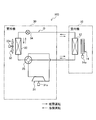
- FIG. 3 is an explanatory view showing the refrigerant circuit Q of the air conditioner 100.
- the solid line arrow of FIG. 3 has shown the flow of the refrigerant
- the broken line arrow in FIG. 3 indicates the flow of the refrigerant during the cooling operation.
- the outdoor unit 30 includes a compressor 31, an outdoor heat exchanger 32, an outdoor fan 33, an outdoor expansion valve 34 (expansion valve), and a four-way valve 35.
- the compressor 31 is a device that compresses a low-temperature low-pressure gas refrigerant and discharges it as a high-temperature high-pressure gas refrigerant by driving the compressor motor 31 a.
- the outdoor heat exchanger 32 is a heat exchanger in which heat exchange is performed between the refrigerant flowing through the heat transfer pipe (not shown) and the outside air fed from the outdoor fan 33.
- the outdoor fan 33 is a fan that sends outside air to the outdoor heat exchanger 32 by the outdoor fan motor 33 a, and is installed near the outdoor heat exchanger 32.
- the outdoor expansion valve 34 has a function of decompressing the refrigerant condensed by the “condenser” (one of the outdoor heat exchanger 32 and the indoor heat exchanger 12). The refrigerant decompressed in the outdoor expansion valve 34 is led to the “evaporator” (the other of the outdoor heat exchanger 32 and the indoor heat exchanger 12).
- the four-way valve 35 is a valve that switches the flow path of the refrigerant according to the operation mode of the air conditioner 100. That is, during the cooling operation (see the broken arrow in FIG. 3), the compressor 31, the outdoor heat exchanger 32 (condenser), the outdoor expansion valve 34, and the indoor heat exchanger 12 (evaporator) are four-way valves.
- the refrigerant circulates in the refrigeration cycle in the refrigerant circuit Q sequentially connected in an annular fashion via the reference numeral 35.
- the compressor 31, the indoor heat exchanger 12 (condenser), the outdoor expansion valve 34, and the outdoor heat exchanger 32 (evaporator) are four-way valves.
- the refrigerant circulates in the refrigeration cycle in the refrigerant circuit Q sequentially connected in an annular fashion via the reference numeral 35.
- one of the "condenser” and the “evaporator” is the outdoor heat exchanger 32, and the other is the indoor heat exchanger 12.
- FIG. 4 is a functional block diagram of the air conditioner 100.
- the indoor unit 10 includes an environment detection unit 21, an indoor control circuit 22, a notification sound generation unit 25 (notification unit), and a display lamp 26 (notification unit), in addition to the above-described configuration.
- the environment detection unit 21 has a function of detecting the state of the room (air conditioned space), and includes an indoor temperature sensor 21a and the like.
- the indoor temperature sensor 21a is a sensor that detects the temperature in the room.
- the detection value of each sensor including the indoor temperature sensor 21 a is output to the indoor control circuit 22.
- the indoor control circuit 22 is configured to include electronic circuits such as a central processing unit (CPU), a read only memory (ROM), a random access memory (RAM), and various interfaces. Then, the program stored in the ROM is read and expanded in the RAM, and the CPU executes various processing.
- CPU central processing unit
- ROM read only memory
- RAM random access memory
- the indoor control circuit 22 includes a storage unit 22 a and an indoor control unit 22 b.
- the storage unit 22a stores, in addition to a predetermined program, the detection result of the environment detection unit 21, data received via the communication unit 11, and the like.
- the indoor control unit 22b executes predetermined control based on the data stored in the storage unit 22a. The processing executed by the indoor control unit 22b will be described later.
- the notification sound generation unit 25 has a function of generating a predetermined notification sound from the indoor unit 10 in which the indoor heat exchanger 12 is accommodated. That is, the notification sound generation unit 25 performs a predetermined notification regarding air conditioning by generating a notification sound such as a buzzer or a voice.
- the display lamp 26 is, for example, an LED (Light Emitting Diode), and performs a predetermined notification regarding air conditioning by lighting (or blinking) in a predetermined color.
- the sound generated by the notification sound generation unit 25 and the color of the display lamp 26 are stored in advance in the storage unit 22a in association with the notification content.
- the outdoor unit 30 shown in FIG. 4 includes an outdoor control circuit 36 in addition to the above-described configuration.
- the outdoor control circuit 36 includes electronic circuits such as a CPU, a ROM, a RAM, and various interfaces, and is connected to the indoor control circuit 22 via a communication line.
- the outdoor control circuit 36 includes a storage unit 36 a and an outdoor control unit 36 b.
- a plurality of sensors an outside air temperature sensor not shown in FIG. 4, a suction pressure sensor of the compressor 31, a discharge pressure sensor The detected values of the discharge temperature sensor etc. are stored.
- the outdoor control unit 36b controls the compressor motor 31a, the outdoor fan motor 33a, the outdoor expansion valve 34, and the like based on the data stored in the storage unit 36a.
- control unit K control means
- the control unit K has a function of controlling the compressor 31 (see FIG. 3), the outdoor expansion valve 34, and the like based on a signal from the remote control 40 or the portable terminal 50.
- the filter 16 for collecting dust and dirt is disposed on the upper side and the front side (air suction side) of the indoor heat exchanger 12 (see FIG. 2).
- the filter 16 for collecting dust and dirt since fine dust and dirt may pass through the filter 16 and adhere to the indoor heat exchanger 12, it is desirable to periodically clean the indoor heat exchanger 12. Therefore, in the present embodiment, the water contained in the air taken into the indoor unit 10 is frozen by the indoor heat exchanger 12, and then the ice of the indoor heat exchanger 12 is melted. Since the dust and dirt adhering to the indoor heat exchanger 12 are washed away by this, the indoor heat exchanger 12 is cleaned. Such a series of processes is referred to as "cleaning process" of the indoor heat exchanger 12.
- FIG. 5 is a flowchart of processing executed by the control unit K of the air conditioner 100 (see FIGS. 3 and 4 as appropriate). It is assumed that a predetermined air conditioning operation (cooling operation, heating operation, etc.) has been performed until "START” in FIG. In addition, it is assumed that the start condition of the cleaning process of the indoor heat exchanger 12 is satisfied at the time of “START” in FIG.
- the “start condition” is, for example, a condition that a value obtained by integrating the execution time of the air conditioning operation from the end time of the previous cleaning process has reached a predetermined value.
- step S101 the control unit K stops the air conditioning operation for a predetermined time (for example, several minutes).
- the aforementioned predetermined time is a time for stabilizing the refrigeration cycle, and is set in advance.
- the control unit K is reverse to the heating operation (same as the cooling operation) Control the four-way valve 35 so that the refrigerant flows.
- the air conditioning operation is stopped for a predetermined time (S101) prior to freezing of the indoor heat exchanger 12 (S102).
- step S101 may be omitted. This is because the direction in which the refrigerant flows during the cooling operation (at the time of “START” in FIG. 5) is the same as the direction in which the refrigerant flows during freezing of the indoor heat exchanger 12 (S102).
- step S102 the control unit K freezes the indoor heat exchanger 12. That is, the control unit K causes the outdoor heat exchanger 32 to function as a condenser, and causes the indoor heat exchanger 12 to function as an evaporator. Thus, the water contained in the air taken into the indoor unit 10 can be frozen by the indoor heat exchanger 12.
- predetermined range is a range in which the moisture contained in the air taken into the indoor unit 10 can be frozen by the indoor heat exchanger 12, and is set in advance.
- control unit K may stop the indoor fan 14 or drive the indoor fan 14. May be
- step S103 the control unit K thaws the indoor heat exchanger 12.
- the control unit K causes the indoor heat exchanger 12 to function as a condenser and causes the outdoor heat exchanger 32 to function as an evaporator.
- the high-temperature refrigerant flows through the indoor heat exchanger 12, which is a condenser, so the ice of the indoor heat exchanger 12 melts.
- dust and dirt adhering to the indoor heat exchanger 12 are washed away.
- the dust and the water containing the dust fall to the drain pan 13 (see FIG. 2), and are discharged to the outside through the drain hose (not shown).
- the controller K may drive the indoor fan 14 while the indoor heat exchanger 12 is being thawed. By this, it can suppress that the temperature of the indoor heat exchanger 12 (condenser) becomes high too much.
- the indoor heat exchanger 12 may be thawed by the control unit K performing the air blowing operation or keeping the stopped state of the device including the compressor 31 and the indoor fan 14 (S103). This is because the ice of the indoor heat exchanger 12 naturally thaws at room temperature even if the control unit K does not cause the indoor heat exchanger 12 to function as a condenser. By this, the power consumption required for thawing the indoor heat exchanger 12 can be reduced.
- step S104 the control unit K dries the indoor heat exchanger 12.
- the control unit K causes the indoor heat exchanger 12 to function as a condenser and causes the outdoor heat exchanger 32 to function as an evaporator.
- the control unit K ends the series of "cleaning process" (END).
- the indoor heat exchanger 12 may be dried by the control unit K performing a blowing operation (that is, driving the indoor fan 14 that feeds air to the indoor heat exchanger 12) (S104). Next, the operation at the time of starting the cleaning process of the indoor heat exchanger 12 will be described in detail.
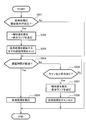
- FIG. 6 is a flowchart showing the process of the control unit K when starting the cleaning process (see FIGS. 3 and 4 as appropriate).
- step S201 the control unit K determines whether the start condition of the cleaning process is satisfied.
- the "cleaning process start condition" is, for example, a condition that a value obtained by integrating the air conditioning operation time from the end of the previous cleaning process has reached a predetermined value.
- step S201: Yes the start condition of the cleaning process is satisfied in step S201 (S201: Yes)
- the process of the control unit K proceeds to step S202.
- the control unit K ends the series of processes (END).
- step S202 the control unit K causes the notification sound generation unit 25 to generate a predetermined notification sound, and turns on the display lamp 26. That is, before starting the cleaning process such as freezing of the indoor heat exchanger 12, the control unit K notifies that the cleaning process is to be performed by the notification sound generation unit 25 and the display lamp 26. Thus, the user can be notified in advance that the cleaning process is to be started.
- step S203 the control unit K sets a delay time (ie, standby time) until the cleaning process of the indoor heat exchanger 12 is started.
- This delay time (for example, several seconds to several tens of seconds) is a time from when the user is notified in advance that cleaning processing is to be started in step S202 to when the cleaning operation is actually started, and is set in advance. There is.
- step S204 the control unit K determines in advance whether or not the user is notified of the start of the cleaning process (S202), and then determines whether a predetermined delay time has elapsed. If the predetermined delay time has elapsed (S204: Yes), the process of the control unit K proceeds to step S205. The lighting of the display lamp 26 (S202) may be continued until the delay time elapses.
- step S205 the control unit K executes the cleaning process (S101 to S104 in FIG. 5) of the indoor heat exchanger 12.
- step S204 the process of the control unit K proceeds to step S206.
- step S206 the control unit K determines whether or not there is an instruction to cancel the cleaning process by the operation of the remote control 40 or the portable terminal 50.
- the processing of the control unit K returns to step S204.
- step S207 the process of the control unit K proceeds to step S207.
- step S207 the control unit K causes the notification sound generation unit 25 to generate a predetermined notification sound, and turns on the display lamp 26.
- the user can be notified that the cleaning operation is actually canceled in response to the operation of the remote control 40 or the like.
- the notification sound and the like (S207) be different from the notification sound and the like (S202) for notifying the cleaning process in advance. This is because the user can be informed in an easy-to-understand manner that the cleaning process is actually canceled.
- step S208 the control unit K cancels the cleaning process of the indoor heat exchanger 12. That is, the control unit K cancels the cleaning process including the freezing of the indoor heat exchanger 12 based on the signal from the remote control 40 or the portable terminal 50. More specifically, when a predetermined cancel instruction is received from the remote control 40 or the portable terminal 50 until a predetermined delay time (predetermined time) elapses from the start of notification (S202) before the cleaning process (S204: No, S206: Yes), the control unit K does not perform the cleaning process including freezing of the indoor heat exchanger 12 (S208). Thus, the control unit K can appropriately cancel the cleaning process of the indoor heat exchanger 12 in accordance with the user's intention. Then, after performing the process of step S208, the control unit K ends the series of processes (END).
- END the series of processes
- control unit K notifies that the cleaning process is to be performed prior to the cleaning process of the indoor heat exchanger 12 (S202). Thus, the user can be informed in advance that the cleaning process is to be performed thereafter.
- the control unit K cancels the cleaning process (S208) .
- This can prevent the cleaning process from being performed against the user's intention.
- the cleaning process of the indoor heat exchanger 12 can be performed according to the user's intention.
- the second embodiment is different from the first embodiment in that processing in the case where there is a cancel instruction during cleaning processing of the indoor heat exchanger 12 (see FIG. 2) is described.
- the other points (the configuration of the air conditioner 100 shown in FIGS. 1 to 4 and the flowchart of the cleaning process shown in FIG. 5) are the same as in the first embodiment. Therefore, only the parts different from the first embodiment will be described, and the descriptions of the overlapping parts will be omitted.
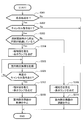
- FIG. 7 is a flowchart showing the process of the control unit K during the cleaning process (see FIGS. 3 and 4 as appropriate).
- the control unit K determines whether the cleaning process is being performed at the present time. The cleaning process is as described in the first embodiment (see FIG. 5).
- the control unit K uses the notification sound generation unit 25 or the display lamp 26 to indicate that the cleaning process is in progress. You may make it alert
- step S301 When the cleaning process is currently performed at step S301 in FIG. 7 (S301: Yes), the process of the control unit K proceeds to step S302. On the other hand, when the cleaning process has not been performed at the present time (S301: No), the control unit K ends the process (END).
- step 302 the control unit K determines whether or not there is an instruction to cancel the cleaning process by the operation of the remote control 40 or the portable terminal 50. If there is no cancellation command for the cleaning process (S302: No), the control unit K continues the cleaning process and then ends the series of processes (END). On the other hand, when there is a cancel instruction of the cleaning process (S302: Yes), the process of the control unit K proceeds to step S303.
- step S303 the control unit K determines whether a predetermined time has elapsed from the start of freezing of the indoor heat exchanger 12.
- a predetermined time for example, several minutes
- the indoor heat exchanger 12 functioning as an evaporator is sufficiently cooled (moisture contained in the air is cooled to the extent that it is frozen by the indoor heat exchanger 12) It is time and is preset.
- step S303 When the predetermined time has elapsed from the start of freezing of the indoor heat exchanger 12 in step S303 (S303: Yes), the process of the control unit K proceeds to step S304. Specifically, control is performed when thawing (S103 in FIG. 5) or drying (S104 in FIG. 5) of the indoor heat exchanger 12 is being performed other than when freezing of the indoor heat exchanger 12 is in progress. The process of part K proceeds to step S304.
- step S304 the control unit K causes the notification sound generation unit 25 to generate a predetermined notification sound, and turns on the display lamp 26.
- the control unit K causes the notification sound generation unit 25 to generate a predetermined notification sound, and turns on the display lamp 26.
- step S305 the control unit K dries the indoor heat exchanger 12. For example, if a predetermined time or more has passed during freezing (S303: Yes), ice may be adhered to the surface of the indoor heat exchanger 12. By evaporating the water after the ice melts at room temperature and further drying it (S305), the anti-bacterial and anti-fungal effect is exhibited. In addition, during thawing of the indoor heat exchanger 12 (S303: Yes), the ice of the indoor heat exchanger 12 melts, a part thereof drips into the drain pan 13 (see FIG. 2), and the rest is the indoor heat exchanger Adhere to 12 By drying the water attached in this manner (S305), the effects of anti-bacterial and anti-mildew are exhibited. Further, during the drying of the indoor heat exchanger 12 (S303: Yes), the drying is continued (S305) to keep the indoor heat exchanger 12 clean.
- step S305 The contents of processing in step S305 are the same as step S104 (see FIG. 5) described in the first embodiment.
- the control unit K dries the indoor heat exchanger 12 by performing a heating operation (making the indoor heat exchanger 12 function as a condenser).
- step S306 the control unit K determines whether or not there is another cancel instruction. That is, the control unit K determines whether or not the predetermined cancel instruction has been received again from the remote controller 40 or the portable terminal 50 while the indoor heat exchanger 12 is drying after receiving the cancel instruction.
- step S306: No When there is no cancel command again in step S306 (S306: No), the process of the control unit K returns to step S305. In this case, the drying of the indoor heat exchanger 12 is continued as it is. On the other hand, when there is a second cancel instruction in step S306 (S306: Yes), the process of the control unit K proceeds to step S307.
- step S307 the control unit K causes the notification sound generation unit 25 to generate a predetermined notification sound, and turns on the display lamp 26. Accordingly, it is possible to notify the user that the cleaning process (that is, the drying of the indoor heat exchanger 12) is actually stopped (S308) according to the cancellation instruction of the cleaning process.
- step S308 the control unit K stops the drying of the indoor heat exchanger 12. By this, even during the drying of the indoor heat exchanger 12, it is possible to appropriately reflect the user's intention to stop the process. After performing the process of step S308, the control unit K ends the series of processes (END).
- step S303 When the predetermined time has not elapsed from the start of freezing of the indoor heat exchanger 12 in step S303 (S303: No), the processing of the control unit K proceeds to step S309.
- step S309 the control unit K causes the notification sound generation unit 25 to generate a predetermined notification sound, and turns on the display lamp 26. Thus, the user can be notified that freezing of the indoor heat exchanger 12 is to be canceled (S310).
- step S310 the control unit K cancels the freezing of the indoor heat exchanger 12.
- the control unit K cancels the freezing of the indoor heat exchanger 12.
- the control unit K cancels the freezing (S310). After performing the process of step S310, the control unit K ends the series of processes (END).
- the control unit K stops the drying of the indoor heat exchanger 12 (S308).
- the third embodiment is different from the first embodiment in that the process when the operation command of the air conditioning operation is received during the cleaning process of the indoor heat exchanger 12 is described.
- the other points (the configuration of the air conditioner 100 shown in FIGS. 1 to 4 and the flowchart of the cleaning process shown in FIG. 5) are the same as in the first embodiment. Therefore, only the parts different from the first embodiment will be described, and the descriptions of the overlapping parts will be omitted.
- FIG. 8 is a flowchart showing processing of the control unit K during or after the cleaning processing (see FIGS. 3 and 4 as appropriate).
- the control unit K determines whether or not an operation command of air conditioning operation (heating operation, cooling operation, and the like) is received from the remote control 40 or the portable terminal 50 during the cleaning process of the indoor heat exchanger 12.
- the process of the control unit K proceeds to step S403.
- the process of the control unit K proceeds to step S402.
- step S402 the control unit K determines whether or not the operation command of the air conditioning operation has been received within a predetermined time from the time of cancellation of the cleaning process of the indoor heat exchanger 12. If the operation command has not been received within the predetermined time since the cancellation of the cleaning process (S402: No), the control unit K ends the series of processes (END).
- step S403 the process of the control unit K proceeds to step S403.
- the cleaning process since the cleaning process is stopped halfway, the ice frozen in the indoor heat exchanger 12 may be melted thereafter and the surface of the indoor heat exchanger 12 may be wet.
- step S403 the control unit K causes the notification sound generation unit 25 to generate a predetermined notification sound, and turns on the display lamp 26.
- the control unit K causes the notification sound generation unit 25 to generate a predetermined notification sound, and turns on the display lamp 26.
- the user can be notified that the operation command of the air conditioning operation has been received.
- step S404 the control unit K stops (or cancels) the cleaning process of the indoor heat exchanger 12. That is, the control unit K stops each device including the compressor 31 and the indoor fan 14.
- step S405 the control unit K determines whether or not a predetermined time has elapsed since the stop (or stop) of the cleaning process.
- the “predetermined time” is a time required to dry the indoor heat exchanger 12 (to evaporate the water adhering to the surface) by continuing the stopped state of each device, and is set in advance.
- step S405: Yes When the predetermined time has elapsed from the stop time of the cleaning process in step S405 (S405: Yes), the process of the control unit K proceeds to step S406. On the other hand, when the predetermined time has not elapsed since the stop of the cleaning process (S405: No), the process of the control unit K returns to step S404.
- step S406 the control unit K sets an execution time for drying the indoor heat exchanger 12. For example, the control unit K sets an execution time of the heating operation or the blowing operation to dry the indoor heat exchanger 12.
- step S407 the control unit K executes drying of the indoor heat exchanger 12.
- the control unit K dries the indoor heat exchanger 12 by performing a heating operation or a blowing operation.
- the indoor heat exchanger 12 may be dried by performing a heating operation and then performing a blowing operation.
- step S408 the control unit K determines whether or not a predetermined execution time (set in S406) has elapsed from the start of the drying of the indoor heat exchanger 12. If the predetermined execution time has elapsed (S408: Yes), the process of the control unit K proceeds to step S409. In this case, the interior of the indoor unit 10 including the indoor heat exchanger 12 is sufficiently dried. On the other hand, if the predetermined execution time has not elapsed from the start of the drying of the indoor heat exchanger 12 (S408: No), the process of the control unit K returns to step S407.
- step S409 the control unit K executes a predetermined air conditioning operation based on the operation command received in step S401 or S402. After performing the process of step S409, the control unit K ends the series of processes (END).
- the control unit K stops the cleaning process and After drying of the indoor heat exchanger 12 is sequentially performed (S404 to S408), the air conditioning operation is performed (S409).
- each embodiment demonstrated the process which wash
- the indoor heat exchanger 12 may be cleaned by condensing the indoor heat exchanger 12.
- the control unit K causes the evaporation temperature of the refrigerant to be lower than that of the normal cooling operation or the dehumidifying operation.
- the control unit K calculates the dew point of the indoor air based on the detection value of the indoor temperature sensor 21a (see FIG. 4) and the detection value of the humidity sensor (not shown).
- the controller K adjusts the degree of opening of the outdoor expansion valve 34 and the like so that the temperature of the indoor heat exchanger 12 is lower than the above-described dew point and higher than a predetermined freezing temperature.
- the above-mentioned "freezing temperature” is a temperature at which the water contained in the room air starts to freeze in the room heat exchanger 12 when the temperature of the room air is lowered.
- control unit K may dry the indoor heat exchanger 12. That is, when the indoor heat exchanger 12 is condensed, the control unit K causes the indoor heat exchanger 12 to function as a condenser, or performs a blowing operation to dry the indoor heat exchanger 12.
- control unit K may perform freezing or condensation of the indoor heat exchanger 12 after the heating operation, the cooling operation, or the dehumidifying operation.
- the indoor heat exchanger 12 can be cleaned after the air conditioning operation such as the heating operation, the cooling operation, the dehumidifying operation and the like.
- the indoor heat exchanger 12 may be cleaned by performing a cooling operation after the heating operation. As a result, moisture adheres to the indoor heat exchanger 12 cooled with the refrigerant, and the indoor heat exchanger 12 is washed away by the moisture.
- each embodiment demonstrated the process which performs the predetermined alerting
- a display (not shown) for performing the above-mentioned notification may be provided in the indoor unit 10, and a predetermined pattern, characters or the like may be displayed on this display.
- predetermined notification may be performed using the remote control 40 (see FIG. 4) or the portable terminal 50 (see FIG. 4). That is, the "notification means" may perform predetermined notification on air conditioning by performing predetermined display on the indoor unit 10, the remote controller 40, or the portable terminal 50.
- a predetermined notification may be performed using one of the notification sound generation unit 25 and the display lamp 26, and the processing of the notification may be omitted as appropriate.
- the notification sound generation unit 25 may not generate the notification sound in a predetermined time zone. For example, it is possible to prevent the user's comfort from being impaired by not generating the notification sound in the night time zone.
- the control unit K make the upper and lower wind direction plates 19 upward than horizontal. This can prevent cold air from directly hitting the user.
- 3rd Embodiment demonstrated the case where the control part K performed each process of step S406-S408 in order to dry the indoor heat exchanger 12, these processes were abbreviate
- the control unit K cancels (stops) the cleaning process (S404). Then, the control unit K starts air conditioning operation based on the operation command after a predetermined time has elapsed after stopping the cleaning process. While the washing process is stopped and each device is stopped, the ice of the indoor heat exchanger 12 is naturally thawed and the water is evaporated. Thereby, thawing and drying of the indoor heat exchanger 12 can be performed.
- the control unit K may perform the following processing. That is, the control unit K may start the air conditioning operation based on the operation command after the predetermined time has elapsed after stopping the cleaning process. This is because the ice of the indoor heat exchanger 12 is naturally thawed and the water is evaporated while the cleaning process is stopped and each device is stopped.
- step S401 or S402 even when the conditions of step S401 or S402 are satisfied, when the operation command received by the control unit K is a heating operation command, the process of steps S406 to S408 (indoor heat exchange) Drying of the vessel 12 may be omitted. This is because the indoor heat exchanger 12 is dried by the subsequent heating operation.
- control unit K may lower the evaporation temperature of the refrigerant when freezing or condensing the indoor heat exchanger 12 than the evaporation temperature of the refrigerant in the dehumidifying operation.
- controller K may set the evaporation temperature of the refrigerant when freezing or condensation of the indoor heat exchanger 12 is below the freezing point.
- each embodiment demonstrated the structure in which the indoor unit 10 (refer FIG. 3) and the outdoor unit 30 (refer FIG. 3) are provided 1 each, it does not restrict to this. That is, a plurality of indoor units connected in parallel may be provided, and a plurality of outdoor units connected in parallel may be provided.
- each embodiment is described in detail for easy understanding of the present invention, and the present invention is not necessarily limited to one having all the configurations described. Moreover, it is possible to add, delete, and replace other configurations for part of the configurations of the respective embodiments. Further, the mechanisms and configurations described above indicate what is considered to be necessary for the description, and not all the mechanisms and configurations of the product are necessarily shown.
Landscapes
- Engineering & Computer Science (AREA)
- Chemical & Material Sciences (AREA)
- Combustion & Propulsion (AREA)
- Mechanical Engineering (AREA)
- General Engineering & Computer Science (AREA)
- Human Computer Interaction (AREA)
- Air Conditioning Control Device (AREA)
- Air Filters, Heat-Exchange Apparatuses, And Housings Of Air-Conditioning Units (AREA)
Abstract
室内熱交換器の洗浄をキャンセルすることが可能な空気調和機を提供する。空気調和機(100)は、圧縮機(31)、凝縮器、室外膨張弁(34)、及び蒸発器を順次に介して、冷凍サイクルで冷媒が循環する冷媒回路(Q)と、少なくとも圧縮機(31)及び室外膨張弁(34)を制御する制御手段と、を備え、前記凝縮器及び前記蒸発器の一方は室外熱交換器(32)であり、他方は室内熱交換器(12)であり、前記制御手段は、室内熱交換器(12)の凍結若しくは結露、又は暖房運転後の冷房運転を、リモコン又は携帯端末からの信号に基づいてキャンセルする。
Description
本発明は、空気調和機に関する。
空気調和機の室内熱交換器を清潔な状態にする技術として、例えば、特許文献1には、「暖房運転後に、前記フィン表面に水を付着させる水分付与手段を備える」空気調和機について記載されている。なお、前記した水付与手段は、暖房運転後に冷房運転を行うことによって、室内熱交換器のフィン表面に水を付着させる。
しかしながら、特許文献1には、水分付与手段の処理をキャンセルする機能については記載されていない。なお、水分付与手段の処理中には、空気調和機の駆動音が発生したり、室内に冷風が吹き出されたりする可能性がある。したがって、水分付与手段による処理がユーザの意図に反して行われることを回避することが望ましい。
そこで、本発明は、室内熱交換器の洗浄をキャンセルすることが可能な空気調和機を提供することを課題とする。
前記課題を解決するために、本発明は、制御手段が、室内熱交換器の凍結若しくは結露、又は暖房運転後の冷房運転を、リモコン又は携帯端末からの信号に基づいてキャンセルすることを特徴とする。
なお、室内熱交換器の凍結等(洗浄)の「キャンセル」とは、凍結等を行う前のキャンセルの他、凍結等を行っているときのキャンセル(中止)も含まれる。
なお、室内熱交換器の凍結等(洗浄)の「キャンセル」とは、凍結等を行う前のキャンセルの他、凍結等を行っているときのキャンセル(中止)も含まれる。
本発明によれば、室内熱交換器の洗浄をキャンセルすることが可能な空気調和機を提供できる。
≪第1実施形態≫
<空気調和機の構成>
図1は、第1実施形態に係る空気調和機100が備える室内機10、室外機30、及びリモコン40の正面図である。
空気調和機100は、冷凍サイクル(ヒートポンプサイクル)で冷媒を循環させることによって、空調を行う機器である。図1に示すように、空気調和機100は、室内(被空調空間)に設置される室内機10と、屋外に設置される室外機30と、ユーザによって操作されるリモコン40と、を備えている。
<空気調和機の構成>
図1は、第1実施形態に係る空気調和機100が備える室内機10、室外機30、及びリモコン40の正面図である。
空気調和機100は、冷凍サイクル(ヒートポンプサイクル)で冷媒を循環させることによって、空調を行う機器である。図1に示すように、空気調和機100は、室内(被空調空間)に設置される室内機10と、屋外に設置される室外機30と、ユーザによって操作されるリモコン40と、を備えている。
室内機10は、通信部11を備えている。この通信部11は、赤外線通信等によって、リモコン40との間で所定の通信を行う。例えば、通信部11は、運転/停止指令、設定温度の変更、運転モードの変更、タイマの設定等の信号をリモコン40から受信する。また、通信部11は、室内温度の検出値等をリモコン40に送信する。なお、通信部11は、携帯電話、スマートフォン、タブレット等の携帯端末50(図4参照)との間で通信を行うことも可能である。
また、図1では省略しているが、室内機10と室外機30とは冷媒配管を介して接続されるとともに、通信線を介して接続されている。
図2は、室内機10の縦断面図である。
室内機10は、前記した通信部11(図1参照)の他に、室内熱交換器12と、ドレンパン13と、室内ファン14と、筐体ベース15と、フィルタ16,16と、前面パネル17と、左右風向板18と、上下風向板19と、を備えている。
室内機10は、前記した通信部11(図1参照)の他に、室内熱交換器12と、ドレンパン13と、室内ファン14と、筐体ベース15と、フィルタ16,16と、前面パネル17と、左右風向板18と、上下風向板19と、を備えている。
室内熱交換器12は、伝熱管12aを通流する冷媒と、室内空気と、の熱交換が行われる熱交換器である。
ドレンパン13は、室内熱交換器12から滴り落ちる水を受けるものであり、室内熱交換器12の下側に配置されている。なお、ドレンパン13に落下した水は、ドレンホース(図示せず)を介して外部に排出される。
ドレンパン13は、室内熱交換器12から滴り落ちる水を受けるものであり、室内熱交換器12の下側に配置されている。なお、ドレンパン13に落下した水は、ドレンホース(図示せず)を介して外部に排出される。
室内ファン14は、例えば、円筒状のクロスフローファンであり、室内ファンモータ14a(図4参照)によって駆動する。
筐体ベース15は、室内熱交換器12や室内ファン14等の機器が設置される筐体である。
筐体ベース15は、室内熱交換器12や室内ファン14等の機器が設置される筐体である。
フィルタ16,16は、空気吸込口h1等を介して取り込まれる空気から塵埃を除去するものであり、室内熱交換器12の上側・前側に設置されている。
前面パネル17は、前側のフィルタ16を覆うように設置されるパネルであり、下端を軸として前側に回動可能になっている。なお、前面パネル17が回動しない構成であってもよい。
前面パネル17は、前側のフィルタ16を覆うように設置されるパネルであり、下端を軸として前側に回動可能になっている。なお、前面パネル17が回動しない構成であってもよい。
左右風向板18は、室内に向けて吹き出される空気の通流方向を、左右方向において調整する板状部材である。左右風向板18は、室内ファン14の下流側に配置され、左右風向板用モータ23(図4参照)によって左右方向に回動するようになっている。
上下風向板19は、室内に向けて吹き出される空気の通流方向を、上下方向において調整する板状部材である。上下風向板19は、室内ファン14の下流側に配置され、上下風向板用モータ24(図4参照)によって上下方向に回動するようになっている。
上下風向板19は、室内に向けて吹き出される空気の通流方向を、上下方向において調整する板状部材である。上下風向板19は、室内ファン14の下流側に配置され、上下風向板用モータ24(図4参照)によって上下方向に回動するようになっている。
空気吸込口h1を介して吸い込まれた空気は、伝熱管12aを通流する冷媒と熱交換し、熱交換した空気が吹出風路h2に導かれる。そして、吹出風路h2を通流する空気は、左右風向板18及び上下風向板19によって所定方向に導かれ、さらに、空気吹出口h3を介して室内に吹き出される。
図3は、空気調和機100の冷媒回路Qを示す説明図である。
なお、図3の実線矢印は、暖房運転時における冷媒の流れを示している。
また、図3の破線矢印は、冷房運転時における冷媒の流れを示している。
図3に示すように、室外機30は、圧縮機31と、室外熱交換器32と、室外ファン33と、室外膨張弁34(膨張弁)と、四方弁35と、を備えている。
なお、図3の実線矢印は、暖房運転時における冷媒の流れを示している。
また、図3の破線矢印は、冷房運転時における冷媒の流れを示している。
図3に示すように、室外機30は、圧縮機31と、室外熱交換器32と、室外ファン33と、室外膨張弁34(膨張弁)と、四方弁35と、を備えている。
圧縮機31は、圧縮機モータ31aの駆動によって、低温低圧のガス冷媒を圧縮し、高温高圧のガス冷媒として吐出する機器である。
室外熱交換器32は、その伝熱管(図示せず)を通流する冷媒と、室外ファン33から送り込まれる外気と、の間で熱交換が行われる熱交換器である。
室外熱交換器32は、その伝熱管(図示せず)を通流する冷媒と、室外ファン33から送り込まれる外気と、の間で熱交換が行われる熱交換器である。
室外ファン33は、室外ファンモータ33aによって、室外熱交換器32に外気を送り込むファンであり、室外熱交換器32の付近に設置されている。
室外膨張弁34は、「凝縮器」(室外熱交換器32及び室内熱交換器12の一方)で凝縮した冷媒を減圧する機能を有している。なお、室外膨張弁34において減圧された冷媒は、「蒸発器」(室外熱交換器32及び室内熱交換器12の他方)に導かれる。
室外膨張弁34は、「凝縮器」(室外熱交換器32及び室内熱交換器12の一方)で凝縮した冷媒を減圧する機能を有している。なお、室外膨張弁34において減圧された冷媒は、「蒸発器」(室外熱交換器32及び室内熱交換器12の他方)に導かれる。
四方弁35は、空気調和機100の運転モードに応じて、冷媒の流路を切り替える弁である。すなわち、冷房運転時(図3の破線矢印を参照)には、圧縮機31、室外熱交換器32(凝縮器)、室外膨張弁34、及び室内熱交換器12(蒸発器)が、四方弁35を介して環状に順次接続されてなる冷媒回路Qにおいて、冷凍サイクルで冷媒が循環する。
また、暖房運転時(図3の実線矢印を参照)には、圧縮機31、室内熱交換器12(凝縮器)、室外膨張弁34、及び室外熱交換器32(蒸発器)が、四方弁35を介して環状に順次接続されてなる冷媒回路Qにおいて、冷凍サイクルで冷媒が循環する。
すなわち、冷媒回路Qにおいて、前記した「凝縮器」及び「蒸発器」の一方は室外熱交換器32であり、他方は室内熱交換器12である。
図4は、空気調和機100の機能ブロック図である。
室内機10は、前記した構成の他に、環境検出部21と、室内制御回路22と、報知音発生部25(報知手段)と、表示ランプ26(報知手段)と、を備えている。
室内機10は、前記した構成の他に、環境検出部21と、室内制御回路22と、報知音発生部25(報知手段)と、表示ランプ26(報知手段)と、を備えている。
環境検出部21は、室内(被空調空間)の状態を検出する機能を有し、室内温度センサ21a等を備えている。
室内温度センサ21aは、室内の温度を検出するセンサである。室内温度センサ21aを含む各センサの検出値は、室内制御回路22に出力される。
室内温度センサ21aは、室内の温度を検出するセンサである。室内温度センサ21aを含む各センサの検出値は、室内制御回路22に出力される。
室内制御回路22は、図示はしないが、CPU(Central Processing Unit)、ROM(Read Only Memory)、RAM(Random Access Memory)、各種インタフェース等の電子回路を含んで構成されている。そして、ROMに記憶されたプログラムを読み出してRAMに展開し、CPUが各種処理を実行するようになっている。
図4に示すように、室内制御回路22は、記憶部22aと、室内制御部22bと、を備えている。
記憶部22aには、所定のプログラムの他、環境検出部21の検出結果や、通信部11を介して受信したデータ等が記憶される。
室内制御部22bは、記憶部22aに記憶されているデータに基づいて、所定の制御を実行する。なお、室内制御部22bが実行する処理については後記する。
記憶部22aには、所定のプログラムの他、環境検出部21の検出結果や、通信部11を介して受信したデータ等が記憶される。
室内制御部22bは、記憶部22aに記憶されているデータに基づいて、所定の制御を実行する。なお、室内制御部22bが実行する処理については後記する。
報知音発生部25は、室内熱交換器12が収容されている室内機10から所定の報知音を発生させる機能を有している。すなわち、報知音発生部25は、ブザーや音声といった報知音を発生させることによって、空調に関する所定の報知を行う。
表示ランプ26は、例えば、LED(Light Emitting Diode)であり、所定の色で点灯(又は点滅)することによって、空調に関する所定の報知を行う。
なお、報知音発生部25が発生する音や、表示ランプ26の色は、報知内容に対応付けて、予め記憶部22aに記憶されている。
表示ランプ26は、例えば、LED(Light Emitting Diode)であり、所定の色で点灯(又は点滅)することによって、空調に関する所定の報知を行う。
なお、報知音発生部25が発生する音や、表示ランプ26の色は、報知内容に対応付けて、予め記憶部22aに記憶されている。
図4に示す室外機30は、前記した構成の他に、室外制御回路36を備えている。
室外制御回路36は、図示はしないが、CPU、ROM、RAM、各種インタフェース等の電子回路を含んで構成され、通信線を介して室内制御回路22に接続されている。図4に示すように、室外制御回路36は、記憶部36aと、室外制御部36bと、を備えている。
室外制御回路36は、図示はしないが、CPU、ROM、RAM、各種インタフェース等の電子回路を含んで構成され、通信線を介して室内制御回路22に接続されている。図4に示すように、室外制御回路36は、記憶部36aと、室外制御部36bと、を備えている。
記憶部36aには、所定のプログラムや、室内制御回路22から受信したデータの他、複数のセンサ(図4では図示を省略している外気温度センサ、圧縮機31の吸入圧力センサ、吐出圧力センサ、吐出温度センサ等)の検出値が記憶される。
室外制御部36bは、記憶部36aに記憶されているデータに基づいて、圧縮機モータ31a、室外ファンモータ33a、室外膨張弁34等を制御する。
室外制御部36bは、記憶部36aに記憶されているデータに基づいて、圧縮機モータ31a、室外ファンモータ33a、室外膨張弁34等を制御する。
以下では、室内制御回路22及び室外制御回路36を「制御部K」(制御手段)という。制御部Kは、リモコン40又は携帯端末50からの信号に基づき、圧縮機31(図3参照)や室外膨張弁34等を制御する機能を有している。
次に、室内熱交換器12を洗浄するための処理について説明する。
前記したように、室内熱交換器12(図2参照)の上側・前側(空気の吸込側)には、塵や埃を捕集するためのフィルタ16が設置されている。しかしながら、細かい塵や埃がフィルタ16を通り抜けて室内熱交換器12に付着することがあるため、室内熱交換器12を定期的に洗浄することが望まれる。そこで、本実施形態では、室内機10に取り込まれた空気に含まれる水分を室内熱交換器12で凍結させ、その後、室内熱交換器12の氷を溶かすようにしている。これによって、室内熱交換器12に付着した塵や埃が洗い流されるため、室内熱交換器12が洗浄される。このような一連の処理を、室内熱交換器12の「洗浄処理」という。
前記したように、室内熱交換器12(図2参照)の上側・前側(空気の吸込側)には、塵や埃を捕集するためのフィルタ16が設置されている。しかしながら、細かい塵や埃がフィルタ16を通り抜けて室内熱交換器12に付着することがあるため、室内熱交換器12を定期的に洗浄することが望まれる。そこで、本実施形態では、室内機10に取り込まれた空気に含まれる水分を室内熱交換器12で凍結させ、その後、室内熱交換器12の氷を溶かすようにしている。これによって、室内熱交換器12に付着した塵や埃が洗い流されるため、室内熱交換器12が洗浄される。このような一連の処理を、室内熱交換器12の「洗浄処理」という。
図5は、空気調和機100の制御部Kが実行する処理のフローチャートである(適宜、図3、図4を参照)。なお、図5の「START」時までは、所定の空調運転(冷房運転、暖房運転等)が行われていたものとする。
また、室内熱交換器12の洗浄処理の開始条件が、図5の「START」時に成立したものとする。この「開始条件」とは、例えば、前回の洗浄処理の終了時から空調運転の実行時間を積算した値が所定値に達したという条件である。
また、室内熱交換器12の洗浄処理の開始条件が、図5の「START」時に成立したものとする。この「開始条件」とは、例えば、前回の洗浄処理の終了時から空調運転の実行時間を積算した値が所定値に達したという条件である。
ステップS101において制御部Kは、空調運転を所定時間(例えば、数分間)停止させる。前記した所定時間は、冷凍サイクルを安定させるための時間であり、予め設定されている。例えば、「START」時まで行われていた暖房運転を中断して、室内熱交換器12を凍結させる際(S102)、制御部Kは、暖房運転時とは逆向き(冷房運転時と同様の向き)に冷媒が流れるように四方弁35を制御する。ここで、仮に、冷媒の流れる向きを急に変えると、圧縮機31に過負荷がかかり、また、冷凍サイクルの不安定化を招く可能性がある。そこで、本実施形態では、室内熱交換器12の凍結(S102)に先立って所定時間、空調運転を停止させるようにしている(S101)。
なお、冷房運転を中断して室内熱交換器12を凍結させる場合には、ステップS101の処理を省略してもよい。冷房運転中(図5の「START」時)に冷媒が流れる向きと、室内熱交換器12の凍結中(S102)に冷媒が流れる向きと、は同じだからである。
次に、ステップS102において制御部Kは、室内熱交換器12を凍結させる。すなわち、制御部Kは、室外熱交換器32を凝縮器として機能させ、室内熱交換器12を蒸発器として機能させる。これによって、室内機10に取り込まれた空気に含まれる水分を室内熱交換器12で凍結させることができる。
室内熱交換器12を凍結させているときには、圧縮機31の回転速度が適宜に調整され、また、室内熱交換器12の温度が所定範囲に収まるように室外膨張弁34の開度が調整される。前記した「所定範囲」とは、室内機10に取り込まれた空気に含まれる水分が、室内熱交換器12で凍結し得る範囲であり、予め設定されている。
なお、室内熱交換器12を凍結させているとき(つまり、所定の凍結時間が経過するまで)、制御部Kは、室内ファン14を停止させてもよいし、また、室内ファン14を駆動させてもよい。
ステップS103において制御部Kは、室内熱交換器12を解凍する。例えば、制御部Kは、室内熱交換器12を凝縮器として機能させ、室外熱交換器32を蒸発器として機能させる。これによって、凝縮器である室内熱交換器12を介して高温の冷媒が流れるため、室内熱交換器12の氷が溶ける。その結果、室内熱交換器12に付着していた塵や埃が洗い流される。そして、塵や埃を含む水がドレンパン13(図2参照)に落下し、ドレンホース(図示せず)を介して外部に排出される。
なお、室内熱交換器12の解凍中、制御部Kが室内ファン14を駆動させるようにしてもよい。これによって、室内熱交換器12(凝縮器)の温度が高くなり過ぎることを抑制できる。
なお、室内熱交換器12の解凍中、制御部Kが室内ファン14を駆動させるようにしてもよい。これによって、室内熱交換器12(凝縮器)の温度が高くなり過ぎることを抑制できる。
また、制御部Kが送風運転を行ったり、圧縮機31や室内ファン14を含む機器の停止状態を継続させたりすることで、室内熱交換器12を解凍するようにしてもよい(S103)。制御部Kが室内熱交換器12を凝縮器として機能させずとも、室内熱交換器12の氷が室温で自然に解凍するからである。これによって、室内熱交換器12の解凍に要する消費電力を低減できる。
ステップS104において制御部Kは、室内熱交換器12を乾燥させる。例えば、制御部Kは、室内熱交換器12を凝縮器として機能させ、室外熱交換器32を蒸発器として機能させる。このように、暖房運転時と同様の制御を行うことで、室内熱交換器12に付着した水分が蒸発するため、防菌・防黴の効果が奏される。ステップS104の処理を行った後、制御部Kは、一連の「洗浄処理」を終了する(END)。
なお、制御部Kが送風運転(つまり、室内熱交換器12に空気を送り込む室内ファン14の駆動)を行うことで、室内熱交換器12を乾燥させるようにしてもよい(S104)。次に、室内熱交換器12の洗浄処理を開始する際の動作について詳細に説明する。
図6は、洗浄処理を開始する際の制御部Kの処理を示すフローチャートである(適宜、図3、図4を参照)。
ステップS201において制御部Kは、洗浄処理の開始条件が成立したか否かを判定する。前記したように、「洗浄処理の開始条件」とは、例えば、前回の洗浄処理の終了時から空調運転の時間を積算した値が所定値に達したという条件である。ステップS201において洗浄処理の開始条件が成立した場合(S201:Yes)、制御部Kの処理はステップS202に進む。一方、洗浄処理の開始条件が成立していない場合(S201:No)、制御部Kは一連の処理を終了する(END)。
ステップS201において制御部Kは、洗浄処理の開始条件が成立したか否かを判定する。前記したように、「洗浄処理の開始条件」とは、例えば、前回の洗浄処理の終了時から空調運転の時間を積算した値が所定値に達したという条件である。ステップS201において洗浄処理の開始条件が成立した場合(S201:Yes)、制御部Kの処理はステップS202に進む。一方、洗浄処理の開始条件が成立していない場合(S201:No)、制御部Kは一連の処理を終了する(END)。
ステップS202において制御部Kは、報知音発生部25によって所定の報知音を発生させ、また、表示ランプ26を点灯させる。すなわち、制御部Kは、室内熱交換器12の凍結等の洗浄処理を開始する前に、この洗浄処理を行う旨を、報知音発生部25及び表示ランプ26によって報知する。これによって、洗浄処理が開始されることをユーザに対して事前に報知できる。
次に、ステップS203において制御部Kは、室内熱交換器12の洗浄処理を開始するまでの遅延時間(つまり、待機時間)を設定する。この遅延時間(例えば、数秒~数十秒)は、ステップS202において洗浄処理を開始する旨をユーザに事前に報知してから、実際に洗浄運転を開始するまでの時間であり、予め設定されている。
ステップS204において制御部Kは、洗浄処理を開始する旨をユーザに事前に報知(S202)してから、所定の遅延時間が経過したか否かを判定する。所定の遅延時間が経過した場合(S204:Yes)、制御部Kの処理はステップS205に進む。この遅延時間が経過するまでの間、表示ランプ26の点灯等(S202)を継続するようにしてもよい。
ステップS205において制御部Kは、室内熱交換器12の洗浄処理(図5のS101~S104)を実行する。
ステップS205において制御部Kは、室内熱交換器12の洗浄処理(図5のS101~S104)を実行する。
一方、ステップS204において所定の遅延時間が経過していない場合(S204:No)、制御部Kの処理はステップS206に進む。
ステップS206において制御部Kは、リモコン40又は携帯端末50の操作によって、洗浄処理のキャンセル指令があったか否かを判定する。洗浄処理のキャンセル指令がない場合(S206:No)、制御部Kの処理はステップS204に戻る。一方、洗浄処理のキャンセル指令があった場合(S204:Yes)、制御部Kの処理はステップS207に進む。
ステップS206において制御部Kは、リモコン40又は携帯端末50の操作によって、洗浄処理のキャンセル指令があったか否かを判定する。洗浄処理のキャンセル指令がない場合(S206:No)、制御部Kの処理はステップS204に戻る。一方、洗浄処理のキャンセル指令があった場合(S204:Yes)、制御部Kの処理はステップS207に進む。
ステップS207において制御部Kは、報知音発生部25によって所定の報知音を発生させ、また、表示ランプ26を点灯させる。これによって、リモコン40等の操作に応じて洗浄運転が実際にキャンセルされることをユーザに報知できる。
なお、前記した報知音等(S207)は、洗浄処理を事前に報知するための報知音等(S202)とは別種類のものであることが望ましい。これによって、洗浄処理が実際にキャンセルされることを、ユーザにわかりやすく報知できるからである。
次に、ステップS208において制御部Kは、室内熱交換器12の洗浄処理をキャンセルする。すなわち、制御部Kは、室内熱交換器12の凍結を含む洗浄処理を、リモコン40又は携帯端末50からの信号に基づいてキャンセルする。さらに詳しく説明すると、洗浄処理前の報知(S202)が開始されてから所定の遅延時間(所定時間)が経過するまでに、リモコン40又は携帯端末50から所定のキャンセル指令を受信した場合(S204:No、S206:Yes)、制御部Kは、室内熱交換器12の凍結を含む洗浄処理を行わない(S208)。これによって、制御部Kは、室内熱交換器12の洗浄処理をユーザの意図に沿って、適切にキャンセルできる。そして、ステップS208の処理を行った後、制御部Kは一連の処理を終了する(END)。
<効果>
第1実施形態によれば、制御部Kは、室内熱交換器12の洗浄処理に先立って、洗浄処理を行う旨を報知する(S202)。これによって、その後に洗浄処理が行われることを、ユーザに対して事前に報知できる。
第1実施形態によれば、制御部Kは、室内熱交換器12の洗浄処理に先立って、洗浄処理を行う旨を報知する(S202)。これによって、その後に洗浄処理が行われることを、ユーザに対して事前に報知できる。
また、洗浄処理の事前の報知(S202)から所定の遅延時間が経過するまでにキャンセル指令があった場合(S204:No、S206:Yes)、制御部Kは、洗浄処理をキャンセルする(S208)。これによって、ユーザの意図に反して洗浄処理が行われることを回避できる。言い換えると、室内熱交換器12の洗浄処理を、ユーザの意図に沿って行うことができる。
≪第2実施形態≫
第2実施形態は、室内熱交換器12(図2参照)の洗浄処理中にキャンセル指令があった場合の処理について説明している点が、第1実施形態とは異なっている。なお、その他の点(図1~図4に示す空気調和機100の構成、図5に示す洗浄処理のフローチャート)については、第1実施形態と同様である。したがって、第1実施形態とは異なる部分について説明し、重複する部分については説明を省略する。
第2実施形態は、室内熱交換器12(図2参照)の洗浄処理中にキャンセル指令があった場合の処理について説明している点が、第1実施形態とは異なっている。なお、その他の点(図1~図4に示す空気調和機100の構成、図5に示す洗浄処理のフローチャート)については、第1実施形態と同様である。したがって、第1実施形態とは異なる部分について説明し、重複する部分については説明を省略する。
図7は、洗浄処理中における制御部Kの処理を示すフローチャートである(適宜、図3、図4を参照)。
ステップS301において制御部Kは、現時点で洗浄処理を行っているか否かを判定する。なお、洗浄処理については、第1実施形態(図5参照)で説明したとおりである。
ステップS301において制御部Kは、現時点で洗浄処理を行っているか否かを判定する。なお、洗浄処理については、第1実施形態(図5参照)で説明したとおりである。
なお、図7では省略しているが、室内熱交換器12の凍結を含む洗浄処理を行っているとき、制御部Kが、洗浄処理中であることを報知音発生部25や表示ランプ26によって報知するようにしてもよい。これによって、室内熱交換器12の洗浄処理が行われていることをユーザが把握しやすくなる。そして、例えば、洗浄処理の継続をユーザが希望しない場合には、リモコン40等の操作によって、所定のキャンセル指令が室内機10に送信される。
図7のステップS301において現時点で洗浄処理中である場合(S301:Yes)、制御部Kの処理はステップS302に進む。一方、現時点では洗浄処理を行っていない場合(S301:No)、制御部Kは処理を終了する(END)。
ステップ302において制御部Kは、リモコン40又は携帯端末50の操作によって、洗浄処理のキャンセル指令があったか否かを判定する。洗浄処理のキャンセル指令がない場合(S302:No)、制御部Kは洗浄処理を継続した後、一連の処理を終了する(END)。一方、洗浄処理のキャンセル指令があった場合(S302:Yes)、制御部Kの処理はステップS303に進む。
次に、ステップS303において制御部Kは、室内熱交換器12の凍結開始時から所定時間が経過したか否かを判定する。この「所定時間」(例えば、数分間)は、蒸発器として機能する室内熱交換器12が十分に冷やされる(空気に含まれる水分が、室内熱交換器12で凍る程度に冷やされる)までの時間であり、予め設定されている。
ステップS303において室内熱交換器12の凍結開始時から所定時間が経過した場合(S303:Yes)、制御部Kの処理はステップS304に進む。具体的に説明すると、室内熱交換器12の凍結が進んでいる場合の他、室内熱交換器12の解凍(図5のS103)や乾燥(図5のS104)が行われているとき、制御部Kの処理はステップS304に進む。
ステップS304において制御部Kは、報知音発生部25によって所定の報知音を発生させ、また、表示ランプ26を点灯させる。これによって、後記するように、洗浄処理のキャンセル指令があったものの(S302:Yes)、敢えて洗浄処理(S305の「乾燥」)を継続する旨をユーザに報知できる。
次に、ステップS305において制御部Kは、室内熱交換器12を乾燥させる。例えば、凍結中に所定時間以上が経過している場合には(S303:Yes)、室内熱交換器12の表面に氷が付着している可能性がある。この氷が室温で溶けた後の水を蒸発させ、さらに乾燥させることで(S305)、防菌・防黴の効果が奏される。
また、室内熱交換器12の解凍中には(S303:Yes)、室内熱交換器12の氷が溶けて、その一部はドレンパン13(図2参照)に滴り落ち、残りは室内熱交換器12に付着する。このように付着した水を乾燥させることで(S305)、防菌・防黴の効果が奏される。
また、室内熱交換器12の乾燥中には(S303:Yes)、その乾燥を継続させて(S305)、室内熱交換器12を清潔な状態にするようにしている。
また、室内熱交換器12の解凍中には(S303:Yes)、室内熱交換器12の氷が溶けて、その一部はドレンパン13(図2参照)に滴り落ち、残りは室内熱交換器12に付着する。このように付着した水を乾燥させることで(S305)、防菌・防黴の効果が奏される。
また、室内熱交換器12の乾燥中には(S303:Yes)、その乾燥を継続させて(S305)、室内熱交換器12を清潔な状態にするようにしている。
このように、室内熱交換器12の凍結を含む洗浄処理を開始してから所定時間が経過した後に(S303:Yes)、リモコン40又は携帯端末50から洗浄処理のキャンセル指令を受信した場合(S302:Yes)、制御部Kは、室内熱交換器12を乾燥させる(S305)。
なお、ステップS305の処理内容については、第1実施形態で説明したステップS104(図5参照)と同様である。その一例を挙げると、制御部Kは、暖房運転を行う(室内熱交換器12を凝縮器として機能させる)ことで、室内熱交換器12を乾燥させる。
次に、ステップS306において制御部Kは、再度のキャンセル指令があったか否かを判定する。すなわち、制御部Kは、キャンセル指令の受信後であって室内熱交換器12の乾燥中、リモコン40又は携帯端末50から所定のキャンセル指令を再び受信したか否かを判定する。
ステップS306において再度のキャンセル指令がない場合(S306:No)、制御部Kの処理はステップS305に戻る。この場合には、室内熱交換器12の乾燥がそのまま継続される。
一方、ステップS306において再度のキャンセル指令があった場合(S306:Yes)、制御部Kの処理はステップS307に進む。
一方、ステップS306において再度のキャンセル指令があった場合(S306:Yes)、制御部Kの処理はステップS307に進む。
ステップS307において制御部Kは、報知音発生部25によって所定の報知音を発生させ、また、表示ランプ26を点灯させる。これによって、洗浄処理のキャンセル指令に応じて実際に洗浄処理(つまり、室内熱交換器12の乾燥)が中止される(S308)ことをユーザに報知できる。
ステップS308において制御部Kは、室内熱交換器12の乾燥を中止する。これによって、室内熱交換器12の乾燥中であっても、その処理を中止させたいというユーザの意図を適切に反映できる。ステップS308の処理を行った後、制御部Kは一連の処理を終了する(END)。
また、ステップS303において室内熱交換器12の凍結開始時から所定時間が経過していない場合(S303:No)、制御部Kの処理はステップS309に進む。
ステップS309において制御部Kは、報知音発生部25によって所定の報知音を発生させ、また、表示ランプ26を点灯させる。これによって、室内熱交換器12の凍結を中止(S310)する旨をユーザに報知できる。
ステップS309において制御部Kは、報知音発生部25によって所定の報知音を発生させ、また、表示ランプ26を点灯させる。これによって、室内熱交換器12の凍結を中止(S310)する旨をユーザに報知できる。
ステップS310において制御部Kは、室内熱交換器12の凍結を中止する。この場合には、室内熱交換器12には氷がほとんど付着していないため、室内熱交換器12の凍結を中止しても支障が生じるおそれはない。つまり、室内熱交換器12の表面に多量の水分が付着して菌や黴が発生するおそれは、ほとんどない。
このように、室内熱交換器12の凍結を開始してから所定時間が経過する前に(S303:No)、リモコン40又は携帯端末50から、前記した凍結のキャンセル指令を受信した場合(S302:Yes)、制御部Kは、その凍結を中止する(S310)。ステップS310の処理を行った後、制御部Kは一連の処理を終了する(END)。
<効果>
第2実施形態によれば、室内熱交換器12の洗浄処理中にキャンセル指令を受信した場合において(S302:Yes)、凍結開始時から所定時間が経過したとき(S303:Yes)、制御部Kは、室内熱交換器12の乾燥を敢えて実行する(S305)。これによって、室内熱交換器12の表面に多量の水が付着することが防止し、防菌・防黴の効果が奏される。
第2実施形態によれば、室内熱交換器12の洗浄処理中にキャンセル指令を受信した場合において(S302:Yes)、凍結開始時から所定時間が経過したとき(S303:Yes)、制御部Kは、室内熱交換器12の乾燥を敢えて実行する(S305)。これによって、室内熱交換器12の表面に多量の水が付着することが防止し、防菌・防黴の効果が奏される。
また、室内熱交換器12の乾燥中に再度のキャンセル指令があった場合(S306:Yes)、制御部Kは、室内熱交換器12の乾燥を中止する(S308)。これによって、室内熱交換器12の乾燥中であっても、その処理を中止させたいというユーザの意図を適切に反映できる。
また、室内熱交換器12の洗浄処理中にキャンセル指令を受信した場合において(S302:Yes)、凍結開始時から所定時間が経過していない場合(S303:No)、制御部Kは、室内熱交換器12の凍結を中止する(S310)。これによって、洗浄処理(凍結)をキャンセルしたいというユーザの意図を適切に反映できる。
≪第3実施形態≫
第3実施形態は、室内熱交換器12の洗浄処理中に空調運転の運転指令を受信した場合の処理について説明している点が、第1実施形態とは異なっている。なお、その他の点(図1~図4に示す空気調和機100の構成、図5に示す洗浄処理のフローチャート)については、第1実施形態と同様である。したがって、第1実施形態とは異なる部分について説明し、重複する部分については説明を省略する。
第3実施形態は、室内熱交換器12の洗浄処理中に空調運転の運転指令を受信した場合の処理について説明している点が、第1実施形態とは異なっている。なお、その他の点(図1~図4に示す空気調和機100の構成、図5に示す洗浄処理のフローチャート)については、第1実施形態と同様である。したがって、第1実施形態とは異なる部分について説明し、重複する部分については説明を省略する。
図8は、洗浄処理中又は洗浄処理後における制御部Kの処理を示すフローチャートである(適宜、図3、図4を参照)。
ステップS401において制御部Kは、室内熱交換器12の洗浄処理中に、リモコン40又は携帯端末50から、空調運転(暖房運転、冷房運転等)の運転指令を受信したか否かを判定する。洗浄処理中に空調運転の運転指令を受信した場合(S401:Yes)、制御部Kの処理はステップS403に進む。この場合には、室内熱交換器12で凍結した氷がその後に溶けたり、解凍後の水が室内熱交換器12に付着していたりする可能性がある。一方、洗浄処理中に空調運転の運転指令を受信していない場合(S401:No)、制御部Kの処理はステップS402に進む。
ステップS401において制御部Kは、室内熱交換器12の洗浄処理中に、リモコン40又は携帯端末50から、空調運転(暖房運転、冷房運転等)の運転指令を受信したか否かを判定する。洗浄処理中に空調運転の運転指令を受信した場合(S401:Yes)、制御部Kの処理はステップS403に進む。この場合には、室内熱交換器12で凍結した氷がその後に溶けたり、解凍後の水が室内熱交換器12に付着していたりする可能性がある。一方、洗浄処理中に空調運転の運転指令を受信していない場合(S401:No)、制御部Kの処理はステップS402に進む。
ステップS402において制御部Kは、室内熱交換器12の洗浄処理のキャンセル時から所定時間内に、空調運転の運転指令を受信したか否かを判定する。洗浄処理のキャンセル時から所定時間内に運転指令を受信していない場合(S402:No)、制御部Kは、一連の処理を終了する(END)。
一方、洗浄処理のキャンセル時から所定時間内に運転指令を受信した場合(S402:Yes)、制御部Kの処理はステップS403に進む。この場合には、洗浄処理が途中で中止されているため、室内熱交換器12で凍結した氷がその後に溶けて、室内熱交換器12の表面が濡れている可能性がある。
ステップS403において制御部Kは、報知音発生部25によって所定の報知音を発生させ、また、表示ランプ26を点灯させる。これによって、空調運転の運転指令を受信した旨をユーザに報知できる。
ステップS404において制御部Kは、室内熱交換器12の洗浄処理を停止(又は中止)させる。つまり、制御部Kは、圧縮機31や室内ファン14を含む各機器を停止させる。
ステップS405において制御部Kは、洗浄処理の停止時(又は中止時)から所定時間が経過したか否かを判定する。この「所定時間」は、各機器の停止状態を継続させることで、室内熱交換器12を乾燥させる(その表面に付着した水分を蒸発させる)のに要する時間であり、予め設定されている。
ステップS405において制御部Kは、洗浄処理の停止時(又は中止時)から所定時間が経過したか否かを判定する。この「所定時間」は、各機器の停止状態を継続させることで、室内熱交換器12を乾燥させる(その表面に付着した水分を蒸発させる)のに要する時間であり、予め設定されている。
ステップS405において洗浄処理の停止時から所定時間が経過した場合(S405:Yes)、制御部Kの処理はステップS406に進む。一方、洗浄処理の停止時から所定時間が経過していない場合(S405:No)、制御部Kの処理はステップS404に戻る。
ステップS406において制御部Kは、室内熱交換器12の乾燥を行うための実行時間をセットする。例えば、制御部Kは、室内熱交換器12を乾燥させるために、暖房運転又は送風運転の実行時間をセットする。
ステップS407において制御部Kは、室内熱交換器12の乾燥を実行する。例えば、制御部Kは、暖房運転又は送風運転を行うことで室内熱交換器12を乾燥させる。なお、暖房運転を行い、さらにその後に送風運転を行うことで室内熱交換器12を乾燥させてもよい。
ステップS408において制御部Kは、室内熱交換器12の乾燥の開始時から所定の実行時間(S406で設定)が経過したか否かを判定する。所定の実行時間が経過した場合(S408:Yes)、制御部Kの処理はステップS409に進む。この場合には、室内熱交換器12を含めて、室内機10の内部が十分に乾燥されている。
一方、室内熱交換器12の乾燥の開始時から所定の実行時間が経過していない場合(S408:No)、制御部Kの処理はステップS407に戻る。
一方、室内熱交換器12の乾燥の開始時から所定の実行時間が経過していない場合(S408:No)、制御部Kの処理はステップS407に戻る。
そして、ステップS409において制御部Kは、ステップS401又はS402で受信した運転指令に基づいて、所定の空調運転を実行する。ステップS409の処理を行った後、制御部Kは一連の処理を終了する(END)。
<効果>
第3実施形態によれば、室内熱交換器12の洗浄処理中又はそのキャンセル時から所定時間内に運転指令を受信した場合(S401又はS402:Yes)、制御部Kは、洗浄処理の停止及び室内熱交換器12の乾燥を順次に行った後(S404~S408)、空調運転を実行する(S409)。これによって、室内熱交換器12が濡れている状態で空調運転の運転指令を受信した場合でも、室内機10の内部を十分に乾燥させた上で空調運転を実行できる。
第3実施形態によれば、室内熱交換器12の洗浄処理中又はそのキャンセル時から所定時間内に運転指令を受信した場合(S401又はS402:Yes)、制御部Kは、洗浄処理の停止及び室内熱交換器12の乾燥を順次に行った後(S404~S408)、空調運転を実行する(S409)。これによって、室内熱交換器12が濡れている状態で空調運転の運転指令を受信した場合でも、室内機10の内部を十分に乾燥させた上で空調運転を実行できる。
≪変形例≫
以上、本発明に係る空気調和機100について各実施形態で説明したが、本発明はこれらの記載に限定されるものではなく、種々の変更を行うことができる。
例えば、各実施形態では、「洗浄処理」として、室内熱交換器12の凍結・解凍・乾燥が順次に行われる場合について説明したが(図5のS102~S104)、これに限らない。例えば、室内熱交換器12の解凍・乾燥のうち一方又は両方を省略してもよい。この場合でも、室内熱交換器12が室温で自然に解凍され、その水によって室内熱交換器12が洗浄されるからである。また、各機器の停止状態の継続や、その後の空調運転等によって、室内熱交換器12が乾燥するからである。
以上、本発明に係る空気調和機100について各実施形態で説明したが、本発明はこれらの記載に限定されるものではなく、種々の変更を行うことができる。
例えば、各実施形態では、「洗浄処理」として、室内熱交換器12の凍結・解凍・乾燥が順次に行われる場合について説明したが(図5のS102~S104)、これに限らない。例えば、室内熱交換器12の解凍・乾燥のうち一方又は両方を省略してもよい。この場合でも、室内熱交換器12が室温で自然に解凍され、その水によって室内熱交換器12が洗浄されるからである。また、各機器の停止状態の継続や、その後の空調運転等によって、室内熱交換器12が乾燥するからである。
また、各実施形態では、室内熱交換器12を凍結させることによって、室内熱交換器12を洗浄する処理について説明したが、これに限らない。例えば、室内熱交換器12を結露させることによって、室内熱交換器12を洗浄するようにしてもよい。この場合において制御部Kは、通常の冷房運転や除湿運転よりも、冷媒の蒸発温度が低くなるようにする。具体的に説明すると、制御部Kは、室内温度センサ21a(図4参照)の検出値と、湿度センサ(図示せず)の検出値と、に基づいて、室内空気の露点を算出する。そして、制御部Kは、室内熱交換器12の温度が、前記した露点以下であり、かつ、所定の凍結温度よりも高くなるように、室外膨張弁34の開度等を調整する。
なお、前記した「凍結温度」とは、室内空気の温度を低下させたとき、室内空気に含まれる水分が、室内熱交換器12で凍結し始める温度である。このように室内熱交換器12を結露させることで、その結露水によって室内熱交換器12を洗浄できる。
なお、前記した「凍結温度」とは、室内空気の温度を低下させたとき、室内空気に含まれる水分が、室内熱交換器12で凍結し始める温度である。このように室内熱交換器12を結露させることで、その結露水によって室内熱交換器12を洗浄できる。
そして、室内熱交換器12を結露させた後、制御部Kが、室内熱交換器12を乾燥させるようにしてもよい。すなわち、室内熱交換器12を結露させた場合において制御部Kは、室内熱交換器12を凝縮器として機能させるか、又は、送風運転を実行することで、室内熱交換器12を乾燥させる。
また、制御部Kが、室内熱交換器12の凍結若しくは結露を、暖房運転、冷房運転、又は除湿運転の後に行うようにしてもよい。これによって、暖房運転、冷房運転、除湿運転等の空調運転後に室内熱交換器12を洗浄できる。
また、室内熱交換器12の凍結や結露の他、暖房運転後に冷房運転を行うことで、室内熱交換器12を洗浄するようにしてもよい。これによって、冷媒で冷やされた室内熱交換器12に水分が付着し、この水分によって室内熱交換器12が洗い流される。
なお、室内熱交換器12の結露や、暖房運転後の冷房運転によって、室内熱交換器12を洗浄するという事項は、各実施形態に適用できる。具体的には、図5のステップS102(凍結)及びステップS103(解凍)の処理に代えて、室内熱交換器12の結露、又は(暖房運転後の)冷房運転を行うようにすればよい。
また、各実施形態では、室内機10の表示ランプ26等(図4参照)によって、空調に関する所定の報知を行う処理について説明したが、これに限らない。例えば、前記した報知を行うためのディスプレイ(図示せず)を室内機10に設け、このディスプレイに所定の絵柄や文字等を表示するようにしてもよい。また、リモコン40(図4参照)又は携帯端末50(図4参照)を用いて、所定の報知を行うようにしてもよい。すなわち、「報知手段」が、室内機10、リモコン40、又は携帯端末50で所定の表示を行うことによって、空調に関する所定の報知を行うようにしてもよい。
また、各実施形態では、報知音発生部25及び表示ランプ26によって、空調運転に関する所定の報知を行う場合について説明したが、これに限らない。例えば、報知音発生部25及び表示ランプ26のうち一方を用いて所定の報知を行ってもよいし、また、報知の処理を適宜に省略してもよい。
また、所定の時間帯において、報知音発生部25が報知音を発生させないようにしてもよい。例えば、夜間の時間帯には報知音を発生させないことで、ユーザの快適性が損なわれることを防止できる。
その他、室内熱交換器12が収容されている室内機10の上下風向板19(図2参照)を開くことによって、凍結を含む洗浄処理がなされていることを報知するようにしてもよい。この場合において制御部Kは、上下風向板19を水平よりも上向きにすることが好ましい。これによって、冷風がユーザに直接あたることを防止できる。
また、第3実施形態(図8参照)では、室内熱交換器12を乾燥させるために、制御部KがステップS406~S408の各処理を行う場合について説明したが、これらの処理を省略してもよい。例えば、室内熱交換器12の凍結(若しくは結露、又は暖房運転後の冷房運転)を含む洗浄処理中、リモコン40又は携帯端末50から空調運転の運転指令を受信した場合(図8のS401:Yes)、制御部Kは、洗浄処理を中止(停止)する(S404)。そして、制御部Kは、洗浄処理を中止してから所定時間が経過した後、運転指令に基づく空調運転を開始する。洗浄処理を中止して各機器を停止させている間に、室内熱交換器12の氷が自然に解凍し、その水が蒸発する。これによって、室内熱交換器12の解凍・乾燥を行うことができる。
また、例えば、室内熱交換器12の凍結(若しくは結露、又は暖房運転後の冷房運転)を含む洗浄処理を、リモコン40又は携帯端末50からのキャンセル指令に基づいて中止してから所定時間が経過する前に、リモコン40又は携帯端末50から空調運転の運転指令を受信したとき(図8のS402:Yes)、制御部Kが次の処理を行うようにしてもよい。すなわち、制御部Kが、洗浄処理を中止してから前記所定時間が経過した後、運転指令に基づく空調運転を開始するようにしてもよい。洗浄処理を中止して各機器を停止させている間に、室内熱交換器12の氷が自然に解凍し、その水が蒸発するからである。
また、第3実施形態において、ステップS401又はS402の条件が成立した場合であっても、制御部Kが受信した運転指令が暖房運転の指令であるときには、ステップS406~S408の処理(室内熱交換器12の乾燥)を省略してもよい。その後の暖房運転によって、室内熱交換器12が乾燥するからである。
また、制御部Kが、室内熱交換器12を凍結又は結露させているときの冷媒の蒸発温度を、除湿運転における冷媒の蒸発温度よりも低くするようにしてもよい。また、制御部Kが、室内熱交換器12を凍結又は結露させているときの冷媒の蒸発温度を氷点下とするようにしてもよい。このような制御を行うことで、室内熱交換器12の凍結又は結露によって、室内熱交換器12に多くの水分(氷や露)が付着する。その結果、室内熱交換器12に付着した水分によって、室内熱交換器12を効果的に洗浄できる。
また、各実施形態では、室内機10(図3参照)及び室外機30(図3参照)が一台ずつ設けられる構成について説明したが、これに限らない。すなわち、並列接続された複数台の室内機を設けてもよいし、また、並列接続された複数台の室外機を設けてもよい。
また、各実施形態は本発明を分かりやすく説明するために詳細に記載したものであり、必ずしも説明した全ての構成を備えるものに限定されない。また、各実施形態の構成の一部について、他の構成の追加・削除・置換をすることが可能である。
また、前記した機構や構成は説明上必要と考えられるものを示しており、製品上必ずしも全ての機構や構成を示しているとは限らない。
また、前記した機構や構成は説明上必要と考えられるものを示しており、製品上必ずしも全ての機構や構成を示しているとは限らない。
100 空気調和機
10 室内機
11 通信部
12 室内熱交換器(蒸発器/凝縮器)
14 室内ファン
18 左右風向板
19 上下風向板
23 左右風向板用モータ
24 上下風向板用モータ(報知手段)
25 報知音発生部(報知手段)
26 表示ランプ(報知手段)
30 室外機
31 圧縮機
32 室外熱交換器(凝縮器/蒸発器)
33 室外ファン
34 室外膨張弁(膨張弁)
35 四方弁
40 リモコン
50 携帯端末
K 制御部(制御手段)
Q 冷媒回路
10 室内機
11 通信部
12 室内熱交換器(蒸発器/凝縮器)
14 室内ファン
18 左右風向板
19 上下風向板
23 左右風向板用モータ
24 上下風向板用モータ(報知手段)
25 報知音発生部(報知手段)
26 表示ランプ(報知手段)
30 室外機
31 圧縮機
32 室外熱交換器(凝縮器/蒸発器)
33 室外ファン
34 室外膨張弁(膨張弁)
35 四方弁
40 リモコン
50 携帯端末
K 制御部(制御手段)
Q 冷媒回路
Claims (15)
- 圧縮機、凝縮器、膨張弁、及び蒸発器を順次に介して、冷凍サイクルで冷媒が循環する冷媒回路と、
少なくとも前記圧縮機及び前記膨張弁を制御する制御手段と、を備え、
前記凝縮器及び前記蒸発器の一方は室外熱交換器であり、他方は室内熱交換器であり、
前記制御手段は、前記室内熱交換器の凍結若しくは結露、又は暖房運転後の冷房運転を、リモコン又は携帯端末からの信号に基づいてキャンセルすること
を特徴とする空気調和機。 - 前記室内熱交換器の凍結又は結露は、暖房運転、冷房運転、又は除湿運転の後に行われること
を特徴とする請求項1に記載の空気調和機。 - 空調に関する所定の報知を行う報知手段を備え、
前記報知手段は、前記室内熱交換器の凍結若しくは結露、又は暖房運転後の冷房運転の処理を開始する前に、当該処理を行う旨の報知を行うこと
を特徴とする請求項1に記載の空気調和機。 - 空調に関する所定の報知を行う報知手段を備え、
前記報知手段は、前記室内熱交換器の凍結若しくは結露、又は暖房運転後の冷房運転の処理を行っているとき、当該処理を行っている旨の報知を行うこと
を特徴とする請求項1に記載の空気調和機。 - 前記報知手段は、前記室内熱交換器が収容されている室内機から所定の報知音を発生させる報知音発生部を有し、
所定の時間帯において前記報知音発生部は、前記報知を行うための報知音を発生させないこと
を特徴とする請求項3又は請求項4に記載の空気調和機。 - 前記報知手段は、前記室内熱交換器が収容されている室内機、前記リモコン、又は前記携帯端末で所定の表示を行うことによって、前記報知を行うこと
を特徴とする請求項3又は請求項4に記載の空気調和機。 - 前記報知手段は、前記室内熱交換器が収容されている室内機の上下風向板を開くことによって、前記報知を行うこと
を特徴とする請求項3又は請求項4に記載の空気調和機。 - 前記制御手段は、前記報知手段による前記報知が開始されてから所定時間が経過するまでに、前記リモコン又は前記携帯端末から所定のキャンセル指令を受信した場合、前記処理を行わないこと
を特徴とする請求項3に記載の空気調和機。 - 前記室内熱交換器の凍結若しくは結露、又は暖房運転後の冷房運転の処理を開始してから所定時間が経過する前に、前記リモコン又は前記携帯端末から当該処理のキャンセル指令を受信した場合、前記制御手段は、当該処理を中止すること
を特徴とする請求項1に記載の空気調和機。 - 前記室内熱交換器の凍結若しくは結露、又は暖房運転後の冷房運転の処理を開始してから所定時間が経過した後に、前記リモコン又は前記携帯端末から当該処理のキャンセル指令を受信した場合、前記制御手段は、前記室内熱交換器の乾燥を行い、
前記乾燥は、前記室内熱交換器に空気を送り込む室内ファンの駆動、又は、前記室内熱交換器を凝縮器として機能させることによって行われること
を特徴とする請求項1に記載の空気調和機。 - 前記キャンセル指令の受信後であって前記室内熱交換器の乾燥中、前記リモコン又は前記携帯端末から所定のキャンセル指令を再び受信した場合、前記制御手段は、前記室内熱交換器の乾燥を中止すること
を特徴とする請求項10に記載の空気調和機。 - 前記室内熱交換器の凍結若しくは結露、又は暖房運転後の冷房運転を含む洗浄処理中、前記リモコン又は前記携帯端末から空調運転の運転指令を受信した場合、前記制御手段は、前記洗浄処理を中止し、さらに、前記洗浄処理を中止してから所定時間が経過した後、前記運転指令に基づく空調運転を開始すること
を特徴とする請求項1に記載の空気調和機。 - 前記室内熱交換器の凍結若しくは結露、又は暖房運転後の冷房運転を含む洗浄処理を、前記リモコン又は前記携帯端末からのキャンセル指令に基づいて中止してから所定時間が経過する前に、前記リモコン又は前記携帯端末から空調運転の運転指令を受信した場合、前記制御手段は、前記所定時間が経過した後、前記運転指令に基づく空調運転を開始すること
を特徴とする請求項1に記載の空気調和機。 - 前記制御手段は、前記室内熱交換器を凍結又は結露させているときの冷媒の蒸発温度を、除湿運転における冷媒の蒸発温度よりも低くすること
を特徴とする請求項1に記載の空気調和機。 - 前記制御手段は、前記室内熱交換器を凍結又は結露させているときの冷媒の蒸発温度を氷点下とすること
を特徴とする請求項1に記載の空気調和機。
Priority Applications (2)
| Application Number | Priority Date | Filing Date | Title |
|---|---|---|---|
| CN201780003132.1A CN109154444B (zh) | 2017-04-28 | 2017-10-03 | 空调机 |
| ES201890016A ES2744324B2 (es) | 2017-04-28 | 2017-10-03 | Aire acondicionadocon sistema de limpieza |
Applications Claiming Priority (2)
| Application Number | Priority Date | Filing Date | Title |
|---|---|---|---|
| JP2017089849A JP6276450B1 (ja) | 2017-04-28 | 2017-04-28 | 空気調和機 |
| JP2017-089849 | 2017-04-28 |
Publications (1)
| Publication Number | Publication Date |
|---|---|
| WO2018198397A1 true WO2018198397A1 (ja) | 2018-11-01 |
Family
ID=61158435
Family Applications (1)
| Application Number | Title | Priority Date | Filing Date |
|---|---|---|---|
| PCT/JP2017/035904 Ceased WO2018198397A1 (ja) | 2017-04-28 | 2017-10-03 | 空気調和機 |
Country Status (7)
| Country | Link |
|---|---|
| JP (1) | JP6276450B1 (ja) |
| CN (1) | CN109154444B (ja) |
| ES (1) | ES2744324B2 (ja) |
| FR (1) | FR3065792B1 (ja) |
| MY (1) | MY168941A (ja) |
| TW (1) | TWI630352B (ja) |
| WO (1) | WO2018198397A1 (ja) |
Cited By (9)
| Publication number | Priority date | Publication date | Assignee | Title |
|---|---|---|---|---|
| WO2020100395A1 (ja) * | 2018-11-14 | 2020-05-22 | ダイキン工業株式会社 | 空気調和機 |
| JP6730536B1 (ja) * | 2019-06-25 | 2020-07-29 | 日立ジョンソンコントロールズ空調株式会社 | 空気調和装置、運転制御方法およびプログラム |
| JP2021038869A (ja) * | 2019-09-02 | 2021-03-11 | ダイキン工業株式会社 | 空調システム |
| CN113587361A (zh) * | 2020-04-30 | 2021-11-02 | 大金工业株式会社 | 空调系统的控制方法以及空调系统 |
| JP2022501561A (ja) * | 2019-08-23 | 2022-01-06 | 海信家電集団股▲ふん▼有限公司 | 空調機及び空調機洗浄方法 |
| WO2022044531A1 (ja) * | 2020-08-26 | 2022-03-03 | ダイキン工業株式会社 | 室内空調システム |
| CN114667421A (zh) * | 2019-11-15 | 2022-06-24 | 大金工业株式会社 | 空调装置 |
| EP3896350A4 (en) * | 2018-12-14 | 2022-08-31 | Qingdao Hisense Hitachi Air-Conditioning Systems Co., Ltd. | MULTISPLIT AIR CONDITIONING SYSTEM AND CONTROL UNIT THEREFOR |
| WO2024106707A1 (ko) * | 2022-11-18 | 2024-05-23 | 삼성전자주식회사 | 환기 시스템 및 그 제어 방법 |
Families Citing this family (9)
| Publication number | Priority date | Publication date | Assignee | Title |
|---|---|---|---|---|
| WO2019229933A1 (ja) * | 2018-05-31 | 2019-12-05 | 日立ジョンソンコントロールズ空調株式会社 | 空気調和機 |
| JP6552773B1 (ja) * | 2018-06-12 | 2019-07-31 | 日立ジョンソンコントロールズ空調株式会社 | 空気調和機 |
| JP7148808B2 (ja) * | 2019-09-02 | 2022-10-06 | ダイキン工業株式会社 | 空調システム |
| JP2021099190A (ja) * | 2019-12-23 | 2021-07-01 | 株式会社富士通ゼネラル | 空気調和装置 |
| CN113614459A (zh) * | 2020-03-05 | 2021-11-05 | 日立江森自控空调有限公司 | 空调机 |
| WO2021176638A1 (ja) * | 2020-03-05 | 2021-09-10 | 日立ジョンソンコントロールズ空調株式会社 | 空気調和機 |
| CN113587397B (zh) * | 2020-04-30 | 2023-06-23 | 大金工业株式会社 | 空调系统控制方法 |
| CN113587398A (zh) * | 2020-04-30 | 2021-11-02 | 大金工业株式会社 | 空调系统的控制方法以及空调系统 |
| JP7082306B1 (ja) * | 2021-05-31 | 2022-06-08 | ダイキン工業株式会社 | 空気調和機 |
Citations (4)
| Publication number | Priority date | Publication date | Assignee | Title |
|---|---|---|---|---|
| JP2001041545A (ja) * | 1999-08-03 | 2001-02-16 | Toshiba Kyaria Kk | 空気調和装置 |
| JP2004020118A (ja) * | 2002-06-19 | 2004-01-22 | Fujitsu General Ltd | 空気調和機の制御方法 |
| JP2010014288A (ja) * | 2008-07-01 | 2010-01-21 | Toshiba Carrier Corp | 空気調和機 |
| JP2012037178A (ja) * | 2010-08-10 | 2012-02-23 | Mitsubishi Electric Corp | 空気調和機の報知装置及び空気調和機 |
Family Cites Families (5)
| Publication number | Priority date | Publication date | Assignee | Title |
|---|---|---|---|---|
| CN102878640A (zh) * | 2012-09-26 | 2013-01-16 | 广东志高空调有限公司 | 一种自动清洁的空调控制方法 |
| CN104930669B (zh) * | 2015-07-07 | 2017-10-27 | 珠海格力电器股份有限公司 | 空调器运行方法 |
| CN105486164A (zh) * | 2016-02-02 | 2016-04-13 | 广东美的制冷设备有限公司 | 空调器室内换热器的清洁控制方法及空调器 |
| CN105757921A (zh) * | 2016-03-28 | 2016-07-13 | 广东志高空调有限公司 | 一种用于空调器的自动清洗提醒系统及其工作方法 |
| CN106545975A (zh) * | 2016-12-08 | 2017-03-29 | 美的集团武汉制冷设备有限公司 | 空调器的换热器清洗控制方法和装置 |
-
2017
- 2017-04-28 JP JP2017089849A patent/JP6276450B1/ja active Active
- 2017-10-03 MY MYPI2018701050A patent/MY168941A/en unknown
- 2017-10-03 CN CN201780003132.1A patent/CN109154444B/zh active Active
- 2017-10-03 ES ES201890016A patent/ES2744324B2/es active Active
- 2017-10-03 WO PCT/JP2017/035904 patent/WO2018198397A1/ja not_active Ceased
- 2017-11-07 TW TW106138403A patent/TWI630352B/zh active
-
2018
- 2018-03-15 FR FR1852218A patent/FR3065792B1/fr active Active
Patent Citations (4)
| Publication number | Priority date | Publication date | Assignee | Title |
|---|---|---|---|---|
| JP2001041545A (ja) * | 1999-08-03 | 2001-02-16 | Toshiba Kyaria Kk | 空気調和装置 |
| JP2004020118A (ja) * | 2002-06-19 | 2004-01-22 | Fujitsu General Ltd | 空気調和機の制御方法 |
| JP2010014288A (ja) * | 2008-07-01 | 2010-01-21 | Toshiba Carrier Corp | 空気調和機 |
| JP2012037178A (ja) * | 2010-08-10 | 2012-02-23 | Mitsubishi Electric Corp | 空気調和機の報知装置及び空気調和機 |
Cited By (22)
| Publication number | Priority date | Publication date | Assignee | Title |
|---|---|---|---|---|
| CN112823262A (zh) * | 2018-11-14 | 2021-05-18 | 大金工业株式会社 | 空调机 |
| JP2020079684A (ja) * | 2018-11-14 | 2020-05-28 | ダイキン工業株式会社 | 空気調和機 |
| WO2020100395A1 (ja) * | 2018-11-14 | 2020-05-22 | ダイキン工業株式会社 | 空気調和機 |
| EP3862642A4 (en) * | 2018-11-14 | 2021-12-01 | Daikin Industries, Ltd. | AIR CONDITIONER |
| CN112823262B (zh) * | 2018-11-14 | 2021-08-31 | 大金工业株式会社 | 空调机 |
| EP3896350A4 (en) * | 2018-12-14 | 2022-08-31 | Qingdao Hisense Hitachi Air-Conditioning Systems Co., Ltd. | MULTISPLIT AIR CONDITIONING SYSTEM AND CONTROL UNIT THEREFOR |
| CN113728205A (zh) * | 2019-06-25 | 2021-11-30 | 日立江森自控空调有限公司 | 空调装置、运转控制方法以及程序 |
| WO2020261360A1 (ja) * | 2019-06-25 | 2020-12-30 | 日立ジョンソンコントロールズ空調株式会社 | 空気調和装置、運転制御方法およびプログラム |
| JP6730536B1 (ja) * | 2019-06-25 | 2020-07-29 | 日立ジョンソンコントロールズ空調株式会社 | 空気調和装置、運転制御方法およびプログラム |
| JP7144463B2 (ja) | 2019-08-23 | 2022-09-29 | 海信家電集団股▲ふん▼有限公司 | 空調機及び空調機洗浄方法 |
| JP2022501561A (ja) * | 2019-08-23 | 2022-01-06 | 海信家電集団股▲ふん▼有限公司 | 空調機及び空調機洗浄方法 |
| WO2021044948A1 (ja) * | 2019-09-02 | 2021-03-11 | ダイキン工業株式会社 | 空調システム |
| JP2021038869A (ja) * | 2019-09-02 | 2021-03-11 | ダイキン工業株式会社 | 空調システム |
| CN114667421A (zh) * | 2019-11-15 | 2022-06-24 | 大金工业株式会社 | 空调装置 |
| CN114667421B (zh) * | 2019-11-15 | 2024-03-08 | 大金工业株式会社 | 空调装置 |
| CN113587361A (zh) * | 2020-04-30 | 2021-11-02 | 大金工业株式会社 | 空调系统的控制方法以及空调系统 |
| JP2022038322A (ja) * | 2020-08-26 | 2022-03-10 | ダイキン工業株式会社 | 室内空調システム |
| WO2022044531A1 (ja) * | 2020-08-26 | 2022-03-03 | ダイキン工業株式会社 | 室内空調システム |
| CN115885134A (zh) * | 2020-08-26 | 2023-03-31 | 大金工业株式会社 | 室内空调系统 |
| CN115885134B (zh) * | 2020-08-26 | 2023-09-22 | 大金工业株式会社 | 室内空调系统 |
| WO2024106707A1 (ko) * | 2022-11-18 | 2024-05-23 | 삼성전자주식회사 | 환기 시스템 및 그 제어 방법 |
| US12523383B2 (en) | 2022-11-18 | 2026-01-13 | Samsung Electronics Co., Ltd. | Ventilation system with cleaning mode and method for controlling the same |
Also Published As
| Publication number | Publication date |
|---|---|
| ES2744324A9 (es) | 2020-03-25 |
| JP6276450B1 (ja) | 2018-02-07 |
| ES2744324R1 (es) | 2020-02-25 |
| CN109154444B (zh) | 2020-01-07 |
| ES2744324A2 (es) | 2020-02-24 |
| ES2744324B2 (es) | 2021-10-08 |
| CN109154444A (zh) | 2019-01-04 |
| MY168941A (en) | 2019-01-10 |
| FR3065792A1 (fr) | 2018-11-02 |
| FR3065792B1 (fr) | 2021-01-29 |
| JP2018189262A (ja) | 2018-11-29 |
| TW201839325A (zh) | 2018-11-01 |
| TWI630352B (zh) | 2018-07-21 |
Similar Documents
| Publication | Publication Date | Title |
|---|---|---|
| JP6276450B1 (ja) | 空気調和機 | |
| JP2018189351A (ja) | 空気調和機 | |
| JP6400242B1 (ja) | 空気調和機 | |
| JP6517877B2 (ja) | 空気調和機 | |
| TWI645135B (zh) | air conditioner | |
| JP6349013B1 (ja) | 空気調和機 | |
| TWI721754B (zh) | 空調機 | |
| TWI681150B (zh) | 空調機 | |
| JP2018200167A (ja) | 空気調和機 | |
| JP6435443B1 (ja) | 空気調和機 | |
| WO2019043765A1 (ja) | 空気調和機 | |
| JP2016161207A (ja) | 空調機 | |
| WO2020070890A1 (ja) | 空気調和機 | |
| JPWO2019239493A1 (ja) | 空気調和機 | |
| WO2022168248A1 (ja) | 空気調和機 |
Legal Events
| Date | Code | Title | Description |
|---|---|---|---|
| WWE | Wipo information: entry into national phase |
Ref document number: P201890016 Country of ref document: ES |
|
| 121 | Ep: the epo has been informed by wipo that ep was designated in this application |
Ref document number: 17906850 Country of ref document: EP Kind code of ref document: A1 |
|
| NENP | Non-entry into the national phase |
Ref country code: DE |
|
| 122 | Ep: pct application non-entry in european phase |
Ref document number: 17906850 Country of ref document: EP Kind code of ref document: A1 |