WO2018198328A1 - 回転電機ユニット - Google Patents
回転電機ユニット Download PDFInfo
- Publication number
- WO2018198328A1 WO2018198328A1 PCT/JP2017/016965 JP2017016965W WO2018198328A1 WO 2018198328 A1 WO2018198328 A1 WO 2018198328A1 JP 2017016965 W JP2017016965 W JP 2017016965W WO 2018198328 A1 WO2018198328 A1 WO 2018198328A1
- Authority
- WO
- WIPO (PCT)
- Prior art keywords
- centrifugal fan
- control unit
- rotating electrical
- casing
- electrical machine
- Prior art date
- Legal status (The legal status is an assumption and is not a legal conclusion. Google has not performed a legal analysis and makes no representation as to the accuracy of the status listed.)
- Ceased
Links
Images

Classifications
-
- H—ELECTRICITY
- H02—GENERATION; CONVERSION OR DISTRIBUTION OF ELECTRIC POWER
- H02K—DYNAMO-ELECTRIC MACHINES
- H02K11/00—Structural association of dynamo-electric machines with electric components or with devices for shielding, monitoring or protection
- H02K11/30—Structural association with control circuits or drive circuits
-
- H—ELECTRICITY
- H02—GENERATION; CONVERSION OR DISTRIBUTION OF ELECTRIC POWER
- H02K—DYNAMO-ELECTRIC MACHINES
- H02K5/00—Casings; Enclosures; Supports
- H02K5/04—Casings or enclosures characterised by the shape, form or construction thereof
- H02K5/22—Auxiliary parts of casings not covered by groups H02K5/06-H02K5/20, e.g. shaped to form connection boxes or terminal boxes
-
- H—ELECTRICITY
- H02—GENERATION; CONVERSION OR DISTRIBUTION OF ELECTRIC POWER
- H02K—DYNAMO-ELECTRIC MACHINES
- H02K7/00—Arrangements for handling mechanical energy structurally associated with dynamo-electric machines, e.g. structural association with mechanical driving motors or auxiliary dynamo-electric machines
- H02K7/14—Structural association with mechanical loads, e.g. with hand-held machine tools or fans
-
- H—ELECTRICITY
- H02—GENERATION; CONVERSION OR DISTRIBUTION OF ELECTRIC POWER
- H02K—DYNAMO-ELECTRIC MACHINES
- H02K9/00—Arrangements for cooling or ventilating
- H02K9/02—Arrangements for cooling or ventilating by ambient air flowing through the machine
- H02K9/04—Arrangements for cooling or ventilating by ambient air flowing through the machine having means for generating a flow of cooling medium
- H02K9/06—Arrangements for cooling or ventilating by ambient air flowing through the machine having means for generating a flow of cooling medium with fans or impellers driven by the machine shaft
Definitions
- the present invention relates to a rotating electrical machine unit.
- a rotation shaft (for example, a crankshaft) of an engine provided in a vehicle or the like is connected to a starter motor that rotationally drives the rotation shaft of the engine with electric power or a rotating electrical machine that constitutes a generator that generates electric power by rotation of the rotation shaft of the engine. ing.
- the operation of this type of rotating electrical machine is controlled by a control unit. For example, when the engine is started by the rotating electrical machine, electric power is supplied from the control unit to the rotating electrical machine. Further, when power is generated in the rotating electrical machine, electric power is supplied from the rotating electrical machine to the control unit.
- Patent Document 1 discloses a configuration in which a control unit is arranged in an engine room so that the influence of heat generated in the engine and hot air due to self-heating of the control unit can be suppressed.
- the control unit when the control unit is arranged at a position away from the rotating electrical machine as in the prior art, the wiring connecting the control unit and the rotating electrical machine becomes long and the voltage loss in the wiring becomes large. is there.
- the engine when the engine is started by the rotating electrical machine, it is necessary to supply electric power from the control unit to the rotating electrical machine at a higher voltage, which increases the power consumption required for starting the engine.
- the electric power generated in the rotating electrical machine is wasted until the power reaches the control unit, and the actual power generation amount is reduced.
- the control unit must be provided with a connector for connecting the control unit to an external device such as a battery.
- the connector is provided so as to protrude from the control unit. However, if the connector is randomly provided to the control unit, the connector may hinder the air flow induced by the fan. In this case, the cooling of the control unit may be insufficient.
- An object of one aspect of the present invention is to provide a rotating electrical machine unit capable of suppressing voltage loss between the rotating electrical machine and a control unit and sufficiently cooling the control unit.
- a rotating electrical machine unit includes a stator, a rotating electrical machine having a rotor that is rotatably provided to the stator, a control unit that controls the operation of the rotating electrical machine, and a projection protruding from the control unit.
- the radial unit is arranged with an interval inside the centrifugal fan in the radial direction when viewed from the axial direction of the centrifugal fan, and the connector protrudes outside the control unit in the radial direction, and the casing Projecting in a direction different from that of the duct.
- a control unit can be arrange
- the protruding direction of the connector with respect to the control unit is different from the direction in which the duct extends in the circumferential direction of the casing, it is possible to suppress a reduction in the intake efficiency of the centrifugal fan. That is, it is possible to suppress the air flow induced by the centrifugal fan from being inhibited by the connector. Thereby, it can suppress suitably that cooling of a control unit becomes inadequate.
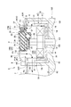
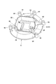
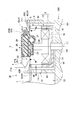
- FIG. 2 is a cross-sectional view taken along the line II-II in FIG. It is a schematic perspective view which shows the case and stay of a control unit which comprise the rotary electric machine unit of FIG. It is a schematic sectional drawing which shows the rotary electric machine unit which concerns on 2nd embodiment of this invention.
- the rotating electrical machine unit 1 includes a rotating electrical machine 2, a control unit 3, a connector 4, a centrifugal fan 5, a casing 6, and a duct 7.
- the rotating electrical machine 2 includes a stator 11 and a rotor 12 that is provided to be rotatable with respect to the stator 11.
- the stator 11 is configured by attaching a plurality of coils 14 to an iron core portion 13.
- the iron core portion 13 includes a plurality of teeth portions (not shown) arranged in a circumferential direction of the rotor body 15 (hereinafter also simply referred to as a circumferential direction).
- the plurality of coils 14 are wound around each tooth portion. That is, the plurality of coils 14 are arranged in the circumferential direction.
- the rotor 12 includes a rotor body 15 formed in a bottomed cylindrical shape, and a plurality of permanent magnets 16 fixed to the rotor body 15 so as to be arranged in the circumferential direction of the rotor body 15.
- the plurality of permanent magnets 16 are arranged so that, for example, the magnetic poles of the surface facing the radial direction of the rotor body 15 (hereinafter also simply referred to as the radial direction) appear alternately in the circumferential direction of the rotor body 15.
- the plurality of permanent magnets 16 are fixed to the inner peripheral surface of the rotor body 15.
- the stator 11 is accommodated in the rotor 12 such that the plurality of permanent magnets 16 face the plurality of coils 14 in the radial direction of the rotor body 15. That is, in the present embodiment, the stator 11 is an inner stator, and the rotor 12 is an outer rotor.
- the rotor 12 of this embodiment is provided so as to rotate together with the rotating shaft 102 (for example, a crankshaft) of the engine 100.
- the rotor 12 may be connected to the rotating shaft 102 via, for example, an endless belt or a gear (both not shown), but in this embodiment, the axis of the rotor 12 (the rotating electrical machine 2) is the axis L1 of the rotating shaft 102. Is directly attached to the rotating shaft 102 so as to coincide with.
- the rotor 12 is attached to a portion of the rotating shaft 102 that protrudes from the main body 101 (for example, an engine block) of the engine 100.
- the rotating electrical machine 2 of the present embodiment is configured as a starter motor that rotationally drives the rotating shaft 102 of the engine 100 with electric power.
- the rotating electrical machine 2 is configured as a generator that generates power by the rotation of the rotating shaft 102 of the engine 100.
- the control unit 3 controls the operation of the rotating electrical machine 2.
- the control unit 3 is electrically connected to the rotating electrical machine 2 (particularly the coil 14) by a wiring (not shown).
- the control unit 3 controls the power supplied to the rotating electrical machine 2 when the rotating electrical machine 2 functions as a starter motor, for example.
- the control unit 3 appropriately adjusts the voltage and current of the power generated by the rotating electrical machine 2 and then charges the generated power to a battery (not shown). Or directly supplied to various electrical components (not shown).
- the control unit 3 of the present embodiment includes a first electronic component 25 that generates a large amount of heat when energized and a second electronic component 26 that generates a smaller amount of heat when energized than the first electronic component 25.
- These electronic components 25 and 26 constitute a control circuit unit 21 for controlling the operation of the rotating electrical machine 2.
- the first electronic component 25 is, for example, a power system component.
- control unit 3 of the present embodiment includes a control circuit unit 21 for controlling the operation of the rotating electrical machine 2. Further, as shown in FIGS. 1 and 2, the control unit 3 of the present embodiment includes a case 22 that houses the control circuit unit 21 and a sealing resin 23 that seals the control circuit unit 21 in the case 22. Prepare.
- the control circuit unit 21 of the present embodiment includes a substrate 24 on which electronic components are mounted in addition to the electronic components 25 and 26 described above.
- the control circuit unit 21 also includes a capacitor 27 that is mounted on the substrate 24 in the same manner as the electronic components 25 and 26.
- the number of the substrates 24 constituting the control circuit unit 21 may be arbitrary, but is two in the present embodiment.
- the form of each substrate 24 (24A, 24B) may be arbitrary.
- the first substrate 24A is a plate-shaped rigid substrate.
- the second substrate 24B is a flexible substrate or a rigid flexible substrate, at least a part of which is flexible.
- the first electronic component 25 and the capacitor 27 described above are mounted on the first substrate 24A.
- a second electronic component 26 is mounted on the second substrate 24B.
- the first substrate 24A and the second substrate 24B are electrically connected to each other by pin terminals (not shown) or the like.
- the case 22 of the control unit 3 makes the appearance of the control unit 3.
- the case 22 is formed in a bottomed cylindrical shape that opens to one side in the thickness direction of the control unit 3.
- the shape of the case 22 viewed from the opening side of the case 22 is not limited to the polygon illustrated in FIG.
- the first electronic component 25, the capacitor 27, and the first substrate 24 ⁇ / b> A are disposed on the bottom of the case 22.
- the second electronic component 26 and the second substrate 24B are disposed above the first substrate 24A.
- the second electronic component 26 is disposed in the vicinity of the opening of the case 22 so as to be located farthest from the first electronic component 25 in the depth direction of the case 22 (vertical direction in FIG. 2).
- the connector 4 is for connecting the control unit 3 to an external device such as a battery or various electric parts.
- the connector 4 is provided so as to protrude from the control unit 3.
- the connector 4 protrudes to the side of the case 22 from the peripheral wall portion of the case 22 of the control unit 3.
- the mode of attaching the connector 4 to the control unit 3 may be arbitrary.
- the connector 4 is attached to the case 22 by being inserted into a cutout portion 28 formed in the peripheral wall portion of the case 22 as shown in FIG.
- the connector 4 is configured such that wiring for connecting the control unit 3 to an external device can be inserted and removed.
- the connector 4 of this embodiment includes a terminal 31 and a cylindrical portion 32.
- the terminal 31 is connected to the control circuit unit 21 of the control unit 3.
- the terminal 31 protrudes to the side of the control unit 3 (case 22).
- the cylindrical portion 32 covers the terminal 31 protruding from the control unit 3.
- the cylindrical portion 32 protrudes to the side of the control unit 3 (case 22), like the terminal 31.
- the protruding directions of the terminal 31 and the cylindrical portion 32 with respect to the control unit 3 coincide with each other.
- the rotating electrical machine unit 1 of this embodiment includes a plurality of connectors 4.
- some of the connectors 4 protrude in the same direction with respect to the control unit 3.
- another connector 4 protrudes in a direction different from the first and second connectors 4A and 4B with respect to the control unit 3.
- the centrifugal fan 5 is formed in a cylindrical shape, and rotates together with the rotor 12 to flow air from the inside to the outside of the centrifugal fan 5 in the radial direction of the centrifugal fan 5.
- the centrifugal fan 5 is configured by arranging the plurality of blades 41 for flowing air in the circumferential direction of the centrifugal fan 5 as described above.
- a symbol R1 in FIG. 1 indicates the rotation direction of the centrifugal fan in the present embodiment.
- the centrifugal fan 5 of the present embodiment is provided so as to rotate together with the rotating shaft 102 of the engine 100, similarly to the rotor 12 described above.
- the centrifugal fan 5 may be connected to the rotating shaft 102 via, for example, an endless belt (not shown) or a gear (not shown), or may be directly attached to the rotating shaft 102.
- the centrifugal fan 5 of the present embodiment is attached to the rotating shaft 102 of the engine 100 via the rotor 12.
- the centrifugal fan 5 and the rotor 12 are aligned in the axial direction and fixed integrally. More specifically, the centrifugal fan 5 and the rotor body 15 of the rotor 12 are formed in a cylindrical shape having the same diameter, and the centrifugal fan 5 and the rotor body 15 are aligned in the axial direction and formed integrally. Has been. For this reason, the axes of the centrifugal fan 5 and the rotor 12 coincide with each other. Further, the axis of centrifugal fan 5 coincides with axis L1 of rotating shaft 102 of engine 100. Further, the rotating electrical machine 2 and the centrifugal fan 5 are arranged in order in a direction away from the main body 101 of the engine 100 in the axial direction.
- the control unit 3 described above is arranged at an interval inside the centrifugal fan 5 in the radial direction when viewed from the axial direction of the centrifugal fan 5.
- an annular gap extending in the circumferential direction of the centrifugal fan 5 is formed between the outside of the control unit 3 and the inside of the centrifugal fan 5 when viewed from the axial direction of the centrifugal fan 5.
- the annular gap is an air inlet P ⁇ b> 1 that sucks air from the outside to the inside of the centrifugal fan 5 in the axial direction of the centrifugal fan 5 while the centrifugal fan 5 is rotating.
- the air inlet P ⁇ b> 1 is divided into a plurality in the circumferential direction of the centrifugal fan 5 by an arm portion 62 of the stay 9 described later.
- control unit 3 is connected to the rotor body 15 in the axial direction of the centrifugal fan 5 on the second end 5B side of the centrifugal fan 5 located on the side opposite to the first end 5A of the centrifugal fan 5 (in FIG. 2). Arranged on the upper side of the centrifugal fan 5.
- the intake port P1 described above is located at the second end portion 5B of the centrifugal fan 5 in the axial direction.
- the rotating electrical machine 2 of the centrifugal fan 5, and the control unit 3 are arranged in order in a direction away from the main body 101 of the engine 100.
- the entire control unit 3 may be disposed outside or inside the centrifugal fan 5 in the axial direction. That is, the entire control unit 3 may or may not be accommodated inside the centrifugal fan 5.
- a part of the control unit 3 is arranged inside the centrifugal fan 5 in the axial direction, and the remaining part of the control unit 3 is arranged outside the centrifugal fan 5 in the axial direction. That is, a part of the control unit 3 is accommodated inside the centrifugal fan 5.
- the first electronic component 25 of the control unit 3 is included in the portion of the control unit 3 disposed inside the centrifugal fan 5 in the axial direction. That is, the first electronic component 25 is disposed inside the centrifugal fan 5 in the axial direction.
- the second electronic component 26 of the control unit 3 is included in the portion of the control unit 3 arranged outside the centrifugal fan 5 in the axial direction. That is, the second electronic component 26 is disposed outside the centrifugal fan 5 in the axial direction.
- the control unit 3 is attached to the stator 11 of the rotating electrical machine 2.
- the control unit 3 may be directly attached to the stator 11, for example.
- the control unit 3 is attached to the stator 11 of the rotating electrical machine 2 via a columnar connection part (projection part) 29 extending in the axial direction of the centrifugal fan 5.
- the connection part 29 may be formed integrally with the case 22 of the control unit 3, for example, or may be formed separately.
- the casing 6 surrounds the outside of the centrifugal fan 5 in the radial direction of the centrifugal fan 5. Moreover, the casing 6 of the present embodiment also surrounds the outside of the rotating electrical machine 2 in the radial direction of the centrifugal fan 5. The casing 6 is located at a distance from the outer periphery of the centrifugal fan 5 and the rotating electrical machine 2 in the radial direction of the centrifugal fan 5.
- the casing 6 may be formed separately from the main body 101 of the engine 100 and attached to the main body 101, for example, but is formed integrally with the main body 101 in this embodiment.
- the casing 6 is formed in a cylindrical shape, but is not limited to this, and it is sufficient that the casing 6 is formed in at least a cylindrical shape.
- the center C1 (axial line L1) of the centrifugal fan 5 and the center (axial line) of the casing 6 are shifted from each other when viewed from the axial direction, and the outer periphery of the centrifugal fan 5 and the casing 6 in the radial direction Is changed in the circumferential direction of the centrifugal fan 5, but is not limited thereto.
- the duct 7 extends from a part of the casing 6 in the circumferential direction to the outside of the casing 6 in the radial direction of the centrifugal fan 5.
- the duct 7 flows the air that has flowed out of the centrifugal fan 5 in the radial direction of the centrifugal fan 5 along with the rotation of the centrifugal fan 5 toward the outside of the casing 6.
- the duct 7 of the present embodiment will be specifically described.
- the duct 7 of the present embodiment includes a through hole 51 formed in a part in the circumferential direction of the casing 6 so as to penetrate in the radial direction of the casing 6.
- the through hole 51 is opened only in a region of the inner peripheral surface of the casing 6 where the blades 41 of the centrifugal fan 5 are opposed, and is not opened in a region where the rotating electrical machine 2 is opposed.
- the duct 7 includes a flow path portion 52 that causes the air that has flowed out of the casing 6 through the through hole 51 to flow in a predetermined direction away from the centrifugal fan 5 and the casing 6.
- the end portion of the flow path portion 52 located on the casing 6 side is located so as to cover the entire region where the through hole 51 opens in the circumferential direction of the casing 6 on the outer peripheral surface of the casing 6.
- the flow path portion 52 may extend in any direction from the casing 6, but extends in the radial direction of the casing 6 in the present embodiment.
- the specific configuration of the flow path portion 52 may be arbitrary. In the present embodiment, a part of the flow path portion 52 is configured by the main body portion 101 of the engine 100. For this reason, the main body 101 of the engine 100 can be cooled by the air flowing out of the casing 6 through the through hole 51. In FIG. 1, the flow path portion 52 becomes thinner as the distance from the casing 6 increases, but the present invention is not limited to this.
- the above-mentioned connector 4 protrudes outside the control unit 3 in the radial direction of the centrifugal fan 5.
- the connector 4 covers a part of the air inlet P1 between the control unit 3 and the centrifugal fan 5 in the circumferential direction of the centrifugal fan 5 when viewed from the axial direction of the centrifugal fan 5.
- the distal end portion of the connector 4 in the protruding direction is located at a distance from the centrifugal fan 5 in the axial direction of the centrifugal fan 5.
- the connector 4 projects in a direction different from the duct 7 in the circumferential direction of the casing 6. For this reason, the region (first region P1A) corresponding to the region where the duct 7 is formed in the circumferential direction in the air inlet P1 between the control unit 3 and the centrifugal fan 5 is not covered by the connector 4.
- the connector 4 covers a region (second region P1B) that does not correspond to the formation region of the duct 7 in the circumferential direction in the air inlet P1.
- the connector 4 may cover the entire second region P1B of the air inlet P1, but in the present embodiment, only a part of the second region P1B is covered. Specifically, the connector 4 covers a portion of the second region P1B extending in the circumferential direction of the centrifugal fan 5 that is adjacent to the first region P1A on the front side in the rotational direction R1 of the centrifugal fan 5. The connector 4 does not cover a portion adjacent to the rear side in the rotation direction R1 of the centrifugal fan 5 with respect to the first region P1A in the second region P1B.
- the connector 4 may protrude from the control unit 3 so as not to interfere with at least the centrifugal fan 5, the casing 6, and a cover portion 8 described later.
- the protruding directions of the first and second connectors 4 ⁇ / b> A and 4 ⁇ / b> B are inclined with respect to the radial direction of the centrifugal fan 5.
- the first and second connectors 4 ⁇ / b> A and 4 ⁇ / b> B are separated from the centrifugal fan 5 in the axial direction of the centrifugal fan 5 toward the outside of the control unit 3 in the radial direction of the centrifugal fan 5 from the control unit 3. It protrudes so as to be inclined.
- the protruding direction of the third connector 4 ⁇ / b> C coincides with the radial direction of the centrifugal fan 5.
- the dimension (width dimension) of the air inlet P1 in the radial direction of the centrifugal fan 5 may be equal between the first region P1A and the second region P1B of the air inlet P1, for example.
- the center C2 of the control unit 3 may be aligned with the center C1 of the centrifugal fan 5, for example, when viewed from the axial direction of the centrifugal fan 5.
- the center C ⁇ b> 2 of the control unit 3 when viewed from the axial direction of the centrifugal fan 5, the center C ⁇ b> 2 of the control unit 3 is shifted from the center C ⁇ b> 1 of the centrifugal fan 5 in a direction away from the duct 7. For this reason, the width dimension of the first area P1A of the air inlet P1 in the radial direction of the centrifugal fan 5 is larger than the width dimension of the second area P1B of the air inlet P1.
- the center C2 of the control unit 3 when viewed from the axial direction of the centrifugal fan 5, the center C2 of the control unit 3 is directed to the portion where the connector 4 is provided in the circumferential direction of the control unit 3 with respect to the center C1 of the centrifugal fan 5. It is staggered. For this reason, the width dimension of the second region P1B of the air inlet P1 in the radial direction of the centrifugal fan 5 is larger than the portion covered by the connector 4 in the second region P1B of the air inlet P1. Is bigger.
- the rotating electrical machine unit 1 of the present embodiment includes a cover portion 8.
- the cover portion 8 may be formed in an arc shape (for example, a C shape) extending in the circumferential direction of the casing 6, for example, but is formed in a ring shape in the present embodiment.
- the cover portion 8 is fixed to the end portion of the casing 6 in the axial direction of the casing 6.
- the cover 8 covers the end of the centrifugal fan 5 in the axial direction of the centrifugal fan 5.
- the cover portion 8 is fixed to the distal end portion of the casing 6 that extends from the main body portion 101 of the engine 100. Moreover, the cover part 8 has covered the 2nd end part 5B of the centrifugal fan 5 located in the same side as the front-end
- the cover 8 is positioned outside the control unit 3 in the radial direction of the centrifugal fan 5 as viewed from the axial direction of the centrifugal fan 5. Further, when viewed from the axial direction of the centrifugal fan 5, the air inlet P ⁇ b> 1 between the control unit 3 and the centrifugal fan 5 is located adjacent to the inner edge of the cover portion 8. That is, the cover portion 8 does not cover the intake port P1.
- the distal end portion of the connector 4 that protrudes outside the control unit 3 in the radial direction of the centrifugal fan 5 is located at an interval in the axial direction of the centrifugal fan 5.
- the cover portion 8 is formed in a plate shape in which the axial direction of the centrifugal fan 5 is the plate thickness direction, but is not limited thereto.
- the rotating electrical machine unit 1 of the present embodiment includes a stay 9 for fixing the control unit 3 to the casing 6 as shown in FIG.
- the stay 9 includes a stay main body 61 fixed to the casing 6 and a plurality of arm portions 62 extending from the stay main body 61 to the case 22 of the control unit 3.
- the stay main body 61 constitutes the cover portion 8 described above.
- the stay main body 61 may be formed in a ring shape extending in the circumferential direction of the casing 6, for example. That is, the stay main body 61 may constitute the entire cover portion 8.
- the stay main body 61 of the present embodiment is formed in an arc shape extending in the circumferential direction of the casing 6. That is, the stay main body 61 of this embodiment constitutes a part of the cover portion 8.
- the remaining portion of the cover portion 8 is configured by an arc-shaped cover structure 63 that is formed separately from the stay main body 61.
- the stay main body 61 includes a plurality of fixing portions 64 for fixing the stay main body 61 to the casing 6.
- the plurality of fixing portions 64 are arranged at intervals in the circumferential direction of the stay main body 61.
- the fixing portion 64 may be arbitrarily configured, but is formed in a cylindrical shape that extends in the axial direction of the stay main body 61 in the present embodiment.
- the cylindrical fixing portion 64 is used for fixing the stay main body 61 to the casing 6 by screwing.
- Each arm portion 62 of the stay 9 projects inward from the inner edge of the stay body 61 in the radial direction of the stay body 61 and reaches the case 22.
- the air inlet P ⁇ b> 1 between the control unit 3 and the centrifugal fan 5 is divided into a plurality of circumferential directions of the centrifugal fan 5 by the plurality of arms 62 of the stay 9. Yes.
- Each arm 62 may be fixed to the case 22 after being formed separately from the case 22 of the control unit 3, for example.
- Each arm 62 in the present embodiment is formed integrally with the case 22 of the control unit 3.
- Each arm 62 is formed in a plate shape that extends in the axial direction of the stay main body 61.
- Each arm portion 62 is arranged on a surface of the stay main body 61 facing the outside of the centrifugal fan 5 in the axial direction (a surface facing the upper side in FIG. 2).
- the fixing portion 64 described above is provided at an end portion of each arm portion 62 on the stay main body 61 side.
- the above-described stay 9 and the case 22 of the control unit 3 formed integrally with the stay 9 may be made of a material having high thermal conductivity such as aluminum.
- control unit 3 the surface facing the outside of the centrifugal fan 5 in the axial direction of the centrifugal fan 5 (the upper surface in FIG. 2) or the outer peripheral surface of the control unit 3 (in the circumferential direction of the centrifugal fan 5). Air flows along the extending surface. Thereby, the control unit 3 is actively cooled by the air flow generated by the rotation of the centrifugal fan 5.
- the air passing through the region (for example, the second region P1B) covered by the connector 4 in the intake port P1 is, for example, as shown by the arrow F2, from the distal end portion in the protruding direction of the connector 4 from the outside of the centrifugal fan 5.
- the air flows through the gap between the cover portion 8 (centrifugal fan 5) and the intake port P1 in order and flows inside the centrifugal fan 5.
- the change of the direction through which air flows is larger than the air which passes through the area
- the intake efficiency of the air flowing into the inside of the centrifugal fan 5 from the intake port P1 as the centrifugal fan 5 rotates (hereinafter referred to as the intake efficiency of the centrifugal fan 5) is the connector 4 of the intake port P1. It is high in the area not covered by the connector and low in the area covered by the connector 4.
- the air that flows into the inside of the centrifugal fan 5 flows from the inside of the centrifugal fan 5 into the gap between the outside of the centrifugal fan 5 and the inside of the casing 6 in the radial direction of the centrifugal fan 5, and further into the casing 6 as indicated by an arrow F3. It flows out to the duct 7 through the formed through hole 51.
- the main body 101 since air flows along the main body 101 of the engine 100 in the duct 7, the main body 101 can be actively cooled.
- the control unit 3 can be actively cooled by the rotation of the centrifugal fan 5.
- the control unit 3 is disposed near the engine 100 together with the rotating electrical machine 2, the wiring connecting the rotating electrical machine 2 and the control unit 3 is shortened, and the voltage loss between the rotating electrical machine 2 and the control unit 3 is reduced. Can be suppressed.
- the electric power generation amount in the rotary electric machine 2 can be increased, or the engine can be started efficiently with low power consumption.
- the protruding direction of the connector 4 is different from the direction in which the duct 7 extends in the circumferential direction of the casing 6. Therefore, it can suppress that the intake efficiency of the centrifugal fan 5 falls.
- this point will be specifically described.
- the suction efficiency of the centrifugal fan 5 is high in the first region P1A corresponding to the formation region of the duct 7 in the circumferential direction of the casing 6 and low in the second region P1B not corresponding to the formation region of the duct 7 in the inlet port P1. That is, the air outside the centrifugal fan 5 is more efficiently introduced into the centrifugal fan 5 in the first region P1A than in the second region P1B of the intake port P1.
- the connector 4 protrudes in a direction different from the direction in which the duct 7 extends in the circumferential direction of the casing 6, thereby covering the second region P ⁇ b> 1 ⁇ / b> B of the air inlet P ⁇ b> 1. For this reason, even if the connector 4 covers a part of the intake port P1, it is possible to prevent the intake efficiency of the centrifugal fan 5 from decreasing.
- the connector 4 protrudes from the control unit 3 in the radial direction of the centrifugal fan 5
- the connector 4 protrudes from the control unit 3 in the axial direction of the centrifugal fan 5.
- the size of the rotating electrical machine unit 1 in the axial direction can be kept small. That is, the rotating electrical machine unit 1 can be reduced in size.
- the centrifugal fan 5 and the cover in the axial direction of the centrifugal fan 5 as the protruding direction of the connector 4 goes to the outside of the control unit 3 in the radial direction of the centrifugal fan 5. Inclined in a direction away from the portion 8. For this reason, in the axial direction of the centrifugal fan 5, the gap between the distal end portion of the connector 4 in the protruding direction and the centrifugal fan 5 can be widened. Thereby, the intake efficiency of the centrifugal fan 5 in the area
- the protruding direction of the connector 4 is inclined with respect to the radial direction of the centrifugal fan 5, the diameter of the centrifugal fan 5 is compared with the case where the protruding direction of the connector 4 matches the radial direction of the centrifugal fan 5.
- the length of the connector 4 in the direction can be substantially shortened. Thereby, size reduction of the rotary electric machine unit 1 can further be achieved.
- the control unit 3 is externally connected as compared with the case where the protruding direction of the connector 4 matches the radial direction of the centrifugal fan 5.
- Wiring for connecting to the device can be easily inserted into and removed from the connector 4. That is, it is possible to improve workability when connecting or disconnecting the control unit 3 and the external device.
- the center C2 of the control unit 3 is shifted in a direction away from the duct 7 with respect to the center C1 of the centrifugal fan 5 when viewed from the axial direction of the centrifugal fan 5. is doing.
- the first region P1A corresponding to the formation region of the duct 7 in the circumferential direction of the casing 6 can be formed wider than the second region P1B not corresponding to the formation region of the duct 7.
- the intake efficiency of the centrifugal fan 5 in the first region P1A of the intake port P1 can be further improved, and the control unit 3 can be cooled more efficiently.
- the second region P1B of the intake port P1 is formed to be smaller, a decrease in the intake efficiency of the centrifugal fan 5 based on the connector 4 covering the second region P1B of the intake port P1 can be further suppressed. .
- the first electronic component 25 having a large calorific value in the control unit 3 is arranged inside the centrifugal fan 5 in the axial direction of the centrifugal fan 5. Since the air flow inside the centrifugal fan 5 is faster than the outside of the centrifugal fan 5, the first electronic component 25 can be efficiently cooled.
- the first electronic component 25 is disposed inside the centrifugal fan 5, and the second electronic component 26 that generates less heat than the first electronic component 25 is a centrifugal fan. 5 is arranged outside.
- the first electronic component 25 and the second electronic component 26 of the control unit 3 are arranged in order in the air flow direction from the outside to the inside of the centrifugal fan 5 in the axial direction of the centrifugal fan 5.
- the heat of the first electronic component 25 can be prevented from reaching the second electronic component 26 through the air flowing around the control unit 3. That is, the second electronic component 26 can be prevented from being heated by the heat generated in the first electronic component 25, and the second electronic component 26 can be protected.
- the case 22 of the control unit 3 is formed integrally with the stay 9. For this reason, the heat generated in the control circuit unit 21 of the control unit 3 can be efficiently released from the case 22 to the stay 9 and can be efficiently dissipated from the stay 9 into the air. Therefore, the control unit 3 can be efficiently cooled.
- the rotating electrical machine unit 1D includes the rotating electrical machine 2, the control unit 3, the connector 4, the centrifugal fan 5, the casing 6, and the duct 7 similar to those in the first embodiment. Moreover, the rotary electric machine unit 1D of this embodiment is fixed to the end part (tip part) of the casing 6 in the axial direction, and the end part (second end part 5B) of the centrifugal fan 5 is fixed in the same manner as the first embodiment.
- a cover portion 8D for covering is provided.
- the cover portion 8D may be formed in an arc shape or a ring shape extending in the circumferential direction of the casing 6.
- a surface of the cover portion 8D that faces the outside of the centrifugal fan 5 in the axial direction of the centrifugal fan 5 (a surface that faces upward in FIG. 2) has an inclined surface 65D.
- the inclined surface 65D is inclined in a direction approaching the centrifugal fan 5 in the axial direction of the centrifugal fan 5 from the outer edge side to the inner edge of the cover portion 8D in the radial direction of the centrifugal fan 5.
- the inclined surface 65D of the cover portion 8D only needs to reach the inner edge of the cover portion 8D at least in the radial direction.
- the inclined surface 65D may reach the outer edge of the cover portion 8D in the radial direction as shown in FIG. 4, but may not reach the outer edge of the cover portion 8D, for example.
- the inclined surface 65D of the cover portion 8D may be formed, for example, on the entire circumferential direction of the cover portion 8D, or may be formed on a part of the cover portion 8D in the circumferential direction.
- the inclined surface 65D is formed in a portion of the cover portion 8D that faces the tip end portion of the connector 4 in the axial direction. Further, the inclined surface 65D is formed to extend outward from the distal end portion of the connector 4 in the radial direction.
- the inclination angle of the inclined surface 65D with respect to the radial direction of the centrifugal fan 5 may be arbitrary.
- the inclination angle of the inclined surface 65 ⁇ / b> D is set so that the inclined surface 65 ⁇ / b> D is parallel to the protruding direction of the connector 4 inclined with respect to the radial direction of the centrifugal fan 5.
- the rotating electrical machine unit 1D of the present embodiment air flows in the state where the centrifugal fan 5 is rotating as in the case of the first embodiment. Further, in the rotating electrical machine unit 1D of the present embodiment, when the centrifugal fan 5 is rotating, a part of the air flowing in the axial direction from the outside to the inside of the centrifugal fan 5 as indicated by an arrow F10, for example. Then, it reaches the inclined surface 65D of the cover portion 8D, flows from the outer edge side of the inclined surface 65D in the radial direction toward the inner edge along the inclined surface 65D, and then flows into the inside of the centrifugal fan 5 from the intake port P1.
- the centrifugal fan 5 when the centrifugal fan 5 is rotating, a part of the air that has reached the inclined surface 65D of the cover portion 8D outside the centrifugal fan 5 is indicated by an arrow F11, for example. As described above, after passing through the gap between the inclined surface 65 ⁇ / b> D and the connector 4, the air flows into the centrifugal fan 5 from the air inlet P ⁇ b> 1.
- the same effects as those of the first embodiment can be obtained. Further, according to the rotating electrical machine unit 1D of the present embodiment, a part of the air flowing from the outside to the inside of the centrifugal fan 5 on the inclined surface 65D of the cover portion 8D when the centrifugal fan 5 is rotating. The air then flows along the inside of the centrifugal fan 5 from the air inlet P1. For this reason, compared with the case where cover part 8D does not have inclined surface 65D, the air of the outer side of the centrifugal fan 5 can be smoothly introduce
- the inclined direction of the inclined surface 65 ⁇ / b> D is parallel to the protruding direction of the connector 4. For this reason, air can flow smoothly in the gap between the inclined surface 65 ⁇ / b> D and the connector 4. Therefore, the intake efficiency of the centrifugal fan 5 can be improved.
- the air that flows out to the duct is not limited to cooling the main body of the engine, but may be a radiator for cooling the engine with water cooling, for example.
- the rotating electrical machine is not limited to the radial gap type rotating electrical machine arranged so that the stator and the rotor face each other in the radial direction, and for example, the stator and the rotor face each other in the axial direction. It may be an axial gap type rotating electrical machine arranged in the above.
- the rotating electrical machine may constitute, for example, only a starter motor or only a generator.
Landscapes
- Engineering & Computer Science (AREA)
- Power Engineering (AREA)
- Motor Or Generator Cooling System (AREA)
- Motor Or Generator Frames (AREA)
- Connection Of Motors, Electrical Generators, Mechanical Devices, And The Like (AREA)
Abstract
回転電機ユニットは、ステータ及びロータを有する回転電機と、回転電機の動作を制御するコントロールユニットと、コントロールユニットから突出して設けられ、コントロールユニットを外部機器に接続するコネクタと、ロータと共に回転することで空気を径方向において内側から外側に流す円筒状の遠心ファンと、径方向において遠心ファンの外側を囲むケーシングと、ケーシングの周方向の一部からケーシングの外側に延びて形成され、遠心ファンの回転に伴って遠心ファンの外側に流れ出た空気をケーシングの外側に流すダクトと、を備える。コントロールユニットは、径方向において遠心ファンの内側に間隔をあけて配される。コネクタは、径方向においてコントロールユニットの外側に突出すると共に、周方向においてダクトと異なる方向に突出している。
Description
この発明は、回転電機ユニットに関する。
車両等に設けられるエンジンの回転軸(例えばクランクシャフト)には、エンジンの回転軸を電力によって回転駆動するスタータモータや、エンジンの回転軸の回転によって発電する発電機を構成する回転電機が接続されている。この種の回転電機の動作は、コントロールユニットによって制御される。例えば、回転電機によってエンジンを始動する際には、コントロールユニットから回転電機に電力が供給される。また、回転電機において発電する際には、回転電機からコントロールユニットに電力が供給される。
一般に、コントロールユニットは熱に弱い電子部品を有する。このため、従来では、回転電機はエンジンの近くに配されるが、コントロールユニットはエンジンから離れた位置に配される。
特許文献1には、エンジンにおいて生じる熱やコントロールユニットの自己発熱による熱気の影響を抑制できるように、エンジンルーム内にコントロールユニットを配置する構成が開示されている。
特許文献1には、エンジンにおいて生じる熱やコントロールユニットの自己発熱による熱気の影響を抑制できるように、エンジンルーム内にコントロールユニットを配置する構成が開示されている。
しかしながら、従来のようにコントロールユニットが回転電機から離れた位置に配されると、コントロールユニットと回転電機とを接続する配線が長くなってしまい、配線における電圧損失が大きくなってしまう、という問題がある。例えば、回転電機によってエンジンを始動する際には、電力をより高い電圧でコントロールユニットから回転電機に供給する必要があるため、エンジンの始動に要する消費電力が大きくなってしまう。また、回転電機において発電された電力が、コントロールユニットに到達するまでに無駄に消費され、実質的な発電量が減少してしまう。一方、上記配線を短くするためには、コントロールユニットも回転電機と同様にエンジンの近くに配する必要があるが、この場合には、コントロールユニットをファン等により積極的に冷却する必要がある。
また、コントロールユニットには、これをバッテリー等の外部機器に接続するためのコネクタを設ける必要がある。コネクタは、コントロールユニットから突出するように設けられる。しかしながら、コネクタをコントロールユニットに対して無作為に設けると、コネクタがファンによって誘起される空気の流れを阻害する可能性がある。この場合、コントロールユニットの冷却が不十分となる可能性がある。
本発明の一態様は、回転電機とコントロールユニットとの間における電圧損失を抑制できると共に、コントロールユニットを十分に冷却することが可能な回転電機ユニットを提供することを目的とする。
本発明の一態様としての回転電機ユニットは、ステータ、及び、該ステータに対して回転自在に設けられるロータを有する回転電機と、前記回転電機の動作を制御するコントロールユニットと、前記コントロールユニットから突出して設けられ、前記コントロールユニットを外部機器に接続するためのコネクタと、円筒状に形成され、前記ロータと共に回転することで空気を径方向において内側から外側に流す遠心ファンと、前記径方向において前記遠心ファンの外側を囲むケーシングと、前記ケーシングの周方向の一部から前記径方向において前記ケーシングの外側に延びて形成され、前記遠心ファンの回転に伴って前記径方向において前記遠心ファンの外側に流れ出た空気を前記ケーシングの外側に流すダクトと、を備え、前記コントロールユニットは、前記遠心ファンの軸方向から見て、前記径方向において前記遠心ファンの内側に間隔をあけて配され、前記コネクタは、前記径方向において前記コントロールユニットの外側に突出すると共に、前記ケーシングの周方向において前記ダクトと異なる方向に突出している。
本発明の一態様によれば、遠心ファンが回転することで、径方向において遠心ファンよりも内側に位置するコントロールユニットの周囲に空気が流れるため、コントロールユニットを積極的に冷却できる。これにより、コントロールユニットを回転電機と共にエンジンの近くに配置し、回転電機とコントロールユニットとの間における電圧損失を抑制することができる。
また、本発明の一態様によれば、コントロールユニットに対するコネクタの突出方向が、ケーシングの周方向においてダクトが延びる方向と異なるため、遠心ファンの吸気効率が低下することを抑制できる。すなわち、遠心ファンによって誘起される空気の流れが、コネクタによって阻害されることを抑制できる。これにより、コントロールユニットの冷却が不十分となることを好適に抑制できる。
〔第一実施形態〕
以下、図1~3を参照して本発明の第一実施形態について説明する。
図1,2に示すように、本実施形態に係る回転電機ユニット1は、回転電機2、コントロールユニット3、コネクタ4、遠心ファン5、ケーシング6及びダクト7を備える。
以下、図1~3を参照して本発明の第一実施形態について説明する。
図1,2に示すように、本実施形態に係る回転電機ユニット1は、回転電機2、コントロールユニット3、コネクタ4、遠心ファン5、ケーシング6及びダクト7を備える。
図2に示すように、回転電機2は、ステータ11、及び、ステータ11に対して回転自在に設けられるロータ12を備える。
ステータ11は、鉄心部13に複数のコイル14を取り付けて構成されている。鉄心部13は、後述するロータ本体15の周方向(以下、単に周方向とも呼ぶ。)に配列された複数のティース部(不図示)を備える。複数のコイル14は、各ティース部に巻き付けられている。すなわち、複数のコイル14は周方向に配列されている。
ステータ11は、鉄心部13に複数のコイル14を取り付けて構成されている。鉄心部13は、後述するロータ本体15の周方向(以下、単に周方向とも呼ぶ。)に配列された複数のティース部(不図示)を備える。複数のコイル14は、各ティース部に巻き付けられている。すなわち、複数のコイル14は周方向に配列されている。
ロータ12は、有底円筒状に形成されたロータ本体15と、ロータ本体15の周方向に配列されるようにロータ本体15に固定される複数の永久磁石16と、を備える。複数の永久磁石16は、例えば、ロータ本体15の径方向(以下、単に径方向とも呼ぶ。)に向く面の磁極がロータ本体15の周方向に交互に現れるように配列される。本実施形態において、複数の永久磁石16はロータ本体15の内周面に固定されている。
ステータ11は、複数の永久磁石16がロータ本体15の径方向において複数のコイル14に対向するように、ロータ12内に収容されている。すなわち、本実施形態において、ステータ11はインナーステータであり、ロータ12はアウターロータである。
ステータ11は、複数の永久磁石16がロータ本体15の径方向において複数のコイル14に対向するように、ロータ12内に収容されている。すなわち、本実施形態において、ステータ11はインナーステータであり、ロータ12はアウターロータである。
本実施形態のロータ12は、エンジン100の回転軸102(例えばクランクシャフト)と共に回転するように設けられる。ロータ12は、例えば無端ベルトやギヤ(いずれも不図示)を介して回転軸102に連結されてもよいが、本実施形態では、ロータ12(回転電機2)の軸線が回転軸102の軸線L1と一致するように、回転軸102に直接取り付けられる。具体的に、ロータ12は、回転軸102のうちエンジン100の本体部101(例えばエンジンブロック)から突出する部位に取り付けられる。
本実施形態の回転電機2は、エンジン100の回転軸102を電力によって回転駆動するスタータモータとして構成される。また、回転電機2は、エンジン100の回転軸102の回転によって発電する発電機として構成される。
コントロールユニット3は、回転電機2の動作を制御する。コントロールユニット3は、不図示の配線によって回転電機2(特にコイル14)に電気接続される。コントロールユニット3は、例えば回転電機2をスタータモータとして機能させる際に、回転電機2に供給する電力を制御する。また、コントロールユニット3は、例えば回転電機2が発電機として機能する際に、回転電機2において発電された電力の電圧や電流を適宜調整した上で、発電電力をバッテリー(不図示)に充電したり、各種電気部品(不図示)に直接供給したりする。
本実施形態のコントロールユニット3は、通電による発熱量が大きい第一電子部品25と、通電による発熱量が第一電子部品25よりも小さい第二電子部品26と、を備える。これら電子部品25,26は、回転電機2の動作を制御するための制御回路部21を構成する。第一電子部品25は、例えばパワー系部品である。
すなわち、本実施形態のコントロールユニット3は、回転電機2の動作を制御するための制御回路部21を備える。さらに、本実施形態のコントロールユニット3は、図1,2に示すように、制御回路部21を収容するケース22と、制御回路部21をケース22内において封止する封止樹脂23と、を備える。
本実施形態の制御回路部21は、上記の電子部品25,26の他に、電子部品を搭載する基板24を含む。また、制御回路部21は、電子部品25,26と同様に基板24に搭載されるコンデンサ27も含む。
制御回路部21を構成する基板24の数は、任意であってよいが、本実施形態では二つである。各基板24(24A,24B)の態様は任意であってよい。本実施形態において、第一基板24Aは、平板状のリジッド基板である。また、第二基板24Bは、少なくとも一部が可撓性を有するフレキシブル基板又はリジッドフレキシブル基板である。第一基板24Aには、前述した第一電子部品25やコンデンサ27が搭載されている。第二基板24Bには、第二電子部品26が搭載されている。第一基板24Aと第二基板24Bとは、ピン端子(不図示)等によって互いに電気接続されている。
コントロールユニット3のケース22は、コントロールユニット3の外観をなす。ケース22は、コントロールユニット3の厚さ方向の一方に開口する有底筒状に形成されている。ケース22の開口側から見たケース22の形状は、図1に例示する多角形に限らず、円形など任意であってよい。
第一電子部品25、コンデンサ27及び第一基板24Aは、ケース22の底部に配されている。第二電子部品26及び第二基板24Bは、第一基板24Aの上方に配されている。特に、第二電子部品26は、ケース22の深さ方向(図2の上下方向)において第一電子部品25から最も離れて位置するように、ケース22の開口近傍に配されている。
コネクタ4は、コントロールユニット3をバッテリーや各種電気部品等の外部機器に接続するためのものである。コネクタ4は、コントロールユニット3から突出して設けられている。本実施形態において、コネクタ4は、コントロールユニット3のケース22の周壁部からケース22の側方に突出している。
コネクタ4をコントロールユニット3に取り付ける態様は任意であってよい。本実施形態において、コネクタ4は、図3に示すように、ケース22の周壁部に形成された切欠部28に挿入することで、ケース22に取り付けられる。
コネクタ4をコントロールユニット3に取り付ける態様は任意であってよい。本実施形態において、コネクタ4は、図3に示すように、ケース22の周壁部に形成された切欠部28に挿入することで、ケース22に取り付けられる。
図1,2に示すように、コネクタ4は、コントロールユニット3を外部機器に接続するための配線を抜き差しできるように構成されている。本実施形態のコネクタ4は、端子31と、筒状部32と、を備える。端子31は、コントロールユニット3の制御回路部21に接続されている。端子31は、コントロールユニット3(ケース22)の側方に突出している。筒状部32は、コントロールユニット3から突出した端子31を覆う。筒状部32は、端子31と同様に、コントロールユニット3(ケース22)の側方に突出している。コントロールユニット3に対する端子31及び筒状部32の突出方向は、互いに一致している。
本実施形態の回転電機ユニット1は、コネクタ4を複数備える。本実施形態において、一部のコネクタ4(第一コネクタ4A、第二コネクタ4B)は、コントロールユニット3に対して同じ方向に突出している。また、別のコネクタ4(第三コネクタ4C)は、コントロールユニット3に対して第一、第二コネクタ4A,4Bと異なる方向に突出している。
遠心ファン5は、円筒状に形成され、ロータ12と共に回転することで空気を遠心ファン5の径方向において遠心ファン5の内側から外側に流す。遠心ファン5は、上記のように空気を流すための複数の羽根41を遠心ファン5の周方向に配列することで構成されている。図1における符号R1は、本実施形態における遠心ファンの回転方向を示している。
図2に示すように、本実施形態の遠心ファン5は、前述したロータ12と同様に、エンジン100の回転軸102と共に回転するように設けられる。遠心ファン5は、例えば、無端ベルト(不図示)やギヤ(不図示)を介して回転軸102に連結されたり、回転軸102に直接取り付けられたりしてもよい。本実施形態の遠心ファン5は、ロータ12を介してエンジン100の回転軸102に取り付けられている。
本実施形態において、遠心ファン5及びロータ12は、これらの軸方向に並べられて一体に固定されている。より具体的に説明すれば、遠心ファン5とロータ12のロータ本体15とが同じ径寸法の円筒状に形成された上で、遠心ファン5及びロータ本体15が軸方向に並べられて一体に形成されている。このため、遠心ファン5及びロータ12の軸線が、互いに一致する。また、遠心ファン5の軸線がエンジン100の回転軸102の軸線L1と一致する。また、回転電機2と遠心ファン5とが、軸方向においてエンジン100の本体部101から離れる方向に順番に並んでいる。
図1,2に示すように、前述したコントロールユニット3は、遠心ファン5の軸方向から見て、径方向において遠心ファン5の内側に間隔をあけて配されている。これにより、遠心ファン5の軸方向から見て、コントロールユニット3の外側と遠心ファン5の内側との間には、遠心ファン5の周方向に延びる環状の隙間が形成されている。
環状の隙間は、遠心ファン5が回転している状態で、空気を遠心ファン5の軸方向において遠心ファン5の外側から内側に吸い込む吸気口P1である。本実施形態において、吸気口P1は、後述するステー9の腕部62により、遠心ファン5の周方向に複数に分割されている。
環状の隙間は、遠心ファン5が回転している状態で、空気を遠心ファン5の軸方向において遠心ファン5の外側から内側に吸い込む吸気口P1である。本実施形態において、吸気口P1は、後述するステー9の腕部62により、遠心ファン5の周方向に複数に分割されている。
また、コントロールユニット3は、遠心ファン5の軸方向においてロータ本体15と接続される遠心ファン5の第一端部5Aと逆側に位置する遠心ファン5の第二端部5B側(図2において遠心ファン5の上側)に配されている。軸方向における遠心ファン5の第二端部5Bには、前述した吸気口P1が位置する。
上記により、本実施形態の回転電機ユニット1では、回転電機2と遠心ファン5とコントロールユニット3とが、エンジン100の本体部101から離れる方向に順番に並んでいる。
上記により、本実施形態の回転電機ユニット1では、回転電機2と遠心ファン5とコントロールユニット3とが、エンジン100の本体部101から離れる方向に順番に並んでいる。
コントロールユニット3は、例えばその全体が軸方向において遠心ファン5の外側又は内側に配されてもよい。すなわち、コントロールユニット3全体が、遠心ファン5の内側に収容されてもよいし、収容されなくてもよい。本実施形態では、コントロールユニット3の一部が軸方向において遠心ファン5の内側に配され、コントロールユニット3の残部が軸方向において遠心ファン5の外側に配されている。すなわち、コントロールユニット3の一部が遠心ファン5の内側に収容されている。
また、軸方向において遠心ファン5の内側に配されるコントロールユニット3の部分には、コントロールユニット3の第一電子部品25が含まれている。すなわち、第一電子部品25は、軸方向において遠心ファン5の内側に配されている。また、軸方向において遠心ファン5の外側に配されるコントロールユニット3の部分には、コントロールユニット3の第二電子部品26が含まれている。すなわち、第二電子部品26は、軸方向において遠心ファン5の外側に配されている。
また、コントロールユニット3は、回転電機2のステータ11に取り付けられている。コントロールユニット3は、例えばステータ11に直接取り付けられてもよい。本実施形態において、コントロールユニット3は、遠心ファン5の軸方向に延びる柱状の接続部(突起部)29を介して、回転電機2のステータ11に取り付けられている。接続部29は、例えばコントロールユニット3のケース22と一体に形成されてもよいし、別個に形成されてもよい。
ケーシング6は、遠心ファン5の径方向において遠心ファン5の外側を囲む。また、本実施形態のケーシング6は、遠心ファン5の径方向において回転電機2の外側も囲む。ケーシング6は、遠心ファン5の径方向において遠心ファン5や回転電機2の外周と間隔をあけて位置している。
ケーシング6は、例えばエンジン100の本体部101と別個に形成されて本体部101に取り付けられてもよいが、本実施形態では本体部101と一体に形成されている。
ケーシング6は、例えばエンジン100の本体部101と別個に形成されて本体部101に取り付けられてもよいが、本実施形態では本体部101と一体に形成されている。
本実施形態では、ケーシング6が円筒状に形成されているが、これに限ることはなく、少なくとも筒状に形成されていればよい。また、本実施形態では、軸方向から見て、遠心ファン5の中心C1(軸線L1)及びケーシング6の中心(軸線)が互いにずれて位置し、径方向における遠心ファン5の外周とケーシング6との間隔が遠心ファン5の周方向において変化しているが、これに限ることはない。
ダクト7は、ケーシング6の周方向の一部から遠心ファン5の径方向においてケーシング6の外側に延びて形成されている。ダクト7は、遠心ファン5の回転に伴って遠心ファン5の径方向において遠心ファン5の外側に流れ出た空気をケーシング6の外側に向けて流す。以下、本実施形態のダクト7について具体的に説明する。
本実施形態のダクト7は、ケーシング6の周方向の一部において、ケーシング6の径方向に貫通して形成された貫通孔51を含む。貫通孔51は、ケーシング6の内周面のうち遠心ファン5の羽根41が対向する領域にのみ開口し、回転電機2が対向する領域には開口しない。
また、ダクト7は、貫通孔51を通してケーシング6の外側に流れ出た空気を遠心ファン5やケーシング6から離れる所定の方向に流す流路部52を含む。ケーシング6側に位置する流路部52の端部は、ケーシング6の外周面のうちケーシング6の周方向において貫通孔51が開口する領域全体を覆うように位置している。流路部52は、ケーシング6から任意の方向に延びていてよいが、本実施形態ではケーシング6の径方向に延びている。
流路部52の具体的な構成は任意であってよい。本実施形態では流路部52の一部がエンジン100の本体部101によって構成されている。このため、貫通孔51を通してケーシング6の外側に流れ出た空気によってエンジン100の本体部101を冷却することができる。図1において流路部52はケーシング6から離れるにしたがって細くなっているが、これに限ることはない。
そして、本実施形態の回転電機ユニット1では、前述のコネクタ4が、遠心ファン5の径方向においてコントロールユニット3の外側に突出している。これにより、コネクタ4は、遠心ファン5の軸方向から見て、コントロールユニット3と遠心ファン5との間の吸気口P1のうち、遠心ファン5の周方向における一部を覆っている。また、コネクタ4の突出方向の先端部は、遠心ファン5の軸方向において遠心ファン5と間隔をあけて位置している。
また、コネクタ4は、ケーシング6の周方向においてダクト7と異なる方向に突出している。このため、コントロールユニット3と遠心ファン5との間の吸気口P1のうち周方向においてダクト7の形成領域に対応する領域(第一領域P1A)は、コネクタ4によって覆われない。コネクタ4は、吸気口P1のうち周方向においてダクト7の形成領域に対応しない領域(第二領域P1B)を覆っている。
コネクタ4は、例えば吸気口P1の第二領域P1B全体を覆ってもよいが、本実施形態では第二領域P1Bの一部のみ覆っている。具体的に、コネクタ4は、遠心ファン5の周方向に延びる第二領域P1Bのうち、第一領域P1Aに対して遠心ファン5の回転方向R1の前側に隣り合う部分を覆っている。コネクタ4は、第二領域P1Bのうち、第一領域P1Aに対して遠心ファン5の回転方向R1の後側に隣り合う部分を覆っていない。
コネクタ4は、少なくとも遠心ファン5やケーシング6、後述するカバー部8に干渉しないように、コントロールユニット3から突出すればよい。
本実施形態では、第一、第二コネクタ4A,4Bの突出方向が、遠心ファン5の径方向に対して傾斜している。具体的に、第一、第二コネクタ4A,4Bは、コントロールユニット3から、遠心ファン5の径方向においてコントロールユニット3の外側に向かうにしたがって、遠心ファン5の軸方向において遠心ファン5から離れる方向に傾斜するように、突出している。
また、本実施形態では、第三コネクタ4Cの突出方向が、遠心ファン5の径方向に一致している。
本実施形態では、第一、第二コネクタ4A,4Bの突出方向が、遠心ファン5の径方向に対して傾斜している。具体的に、第一、第二コネクタ4A,4Bは、コントロールユニット3から、遠心ファン5の径方向においてコントロールユニット3の外側に向かうにしたがって、遠心ファン5の軸方向において遠心ファン5から離れる方向に傾斜するように、突出している。
また、本実施形態では、第三コネクタ4Cの突出方向が、遠心ファン5の径方向に一致している。
回転電機ユニット1において、遠心ファン5の径方向における吸気口P1の寸法(幅寸法)は、例えば吸気口P1の第一領域P1Aと第二領域P1Bとの間で互いに同等であってもよい。この場合、遠心ファン5の軸方向から見て、コントロールユニット3の中心C2を、例えば遠心ファン5の中心C1と一致させればよい。
本実施形態では、遠心ファン5の軸方向から見て、コントロールユニット3の中心C2が、遠心ファン5の中心C1に対して、ダクト7から離れる方向にずれて位置している。このため、遠心ファン5の径方向における吸気口P1の第一領域P1Aの幅寸法が、吸気口P1の第二領域P1Bの幅寸法よりも大きくなっている。
また、本実施形態では、遠心ファン5の軸方向から見て、コントロールユニット3の中心C2が、遠心ファン5の中心C1に対して、コントロールユニット3の周方向においてコネクタ4を設けた部分に向けてずらして位置している。このため、遠心ファン5の径方向における吸気口P1の第二領域P1Bの幅寸法は、吸気口P1の第二領域P1Bのうちコネクタ4によって覆われる部分よりも、コネクタ4によって覆われない部分の方が大きい。
さらに、本実施形態の回転電機ユニット1は、カバー部8を備える。カバー部8は、例えばケーシング6の周方向に延びる弧状(例えばC字状)に形成されてもよいが、本実施形態ではリング状に形成されている。カバー部8は、ケーシング6の軸方向におけるケーシング6の端部に固定される。また、カバー部8は、遠心ファン5の軸方向における遠心ファン5の端部を覆う。
具体的に、カバー部8は、エンジン100の本体部101から延びるケーシング6の先端部に固定されている。また、カバー部8は、軸方向においてケーシング6の先端部と同じ側に位置する遠心ファン5の第二端部5Bを覆っている。これにより、カバー部8は、遠心ファン5の軸方向から見て、遠心ファン5とケーシング6との隙間を覆っている。
本実施形態において、カバー部8は、遠心ファン5の軸方向から見て、遠心ファン5の径方向においてコントロールユニット3の外側に間隔をあけて位置している。また、遠心ファン5の軸方向から見て、カバー部8の内縁には、コントロールユニット3と遠心ファン5との間の吸気口P1が隣り合せて位置している。すなわち、カバー部8は吸気口P1を覆わない。
本実施形態において、上記したカバー部8には、遠心ファン5の径方向においてコントロールユニット3の外側に突出するコネクタ4の先端部が、遠心ファン5の軸方向において間隔をあけて位置している。
本実施形態において、カバー部8は遠心ファン5の軸方向を板厚方向とする板状に形成されているが、これに限ることはない。
本実施形態において、カバー部8は遠心ファン5の軸方向を板厚方向とする板状に形成されているが、これに限ることはない。
また、本実施形態の回転電機ユニット1は、図1-3に示すように、コントロールユニット3をケーシング6に固定するためのステー9を備える。ステー9は、ケーシング6に固定されるステー本体61と、ステー本体61からコントロールユニット3のケース22まで延びる複数の腕部62と、を備える。
ステー本体61は、前述したカバー部8を構成している。ステー本体61は、例えばケーシング6の周方向に延びるリング状に形成されてもよい。すなわち、ステー本体61はカバー部8全体を構成してもよい。本実施形態のステー本体61はケーシング6の周方向に延びる弧状に形成されている。すなわち、本実施形態のステー本体61は、カバー部8の一部を構成している。本実施形態において、カバー部8の残部は、ステー本体61とは別個に形成された弧状のカバー構成体63によって構成されている。
ステー本体61は、これをケーシング6に固定するための複数の固定部64を含む。複数の固定部64は、ステー本体61の周方向に互いに間隔をあけて配列されている。固定部64は任意に構成されてよいが、本実施形態ではステー本体61の軸方向に延びる筒状に形成されている。筒状の固定部64は、ネジ止めによりステー本体61をケーシング6に固定するために利用される。
ステー9の各腕部62は、ステー本体61の径方向においてステー本体61の内縁から内側に突出し、ケース22に到達している。これにより、遠心ファン5の軸方向から見て、コントロールユニット3と遠心ファン5との間の吸気口P1は、ステー9の複数の腕部62によって遠心ファン5の周方向に複数に分割されている。
各腕部62は、例えばコントロールユニット3のケース22と別個に形成された上でケース22に固定されてもよい。本実施形態の各腕部62は、コントロールユニット3のケース22と一体に形成されている。
また、各腕部62は、ステー本体61の軸方向に延びる板状に形成されている。各腕部62は、ステー本体61のうち軸方向において遠心ファン5の外側に向く面(図2において上側に向く面)に配されている。各腕部62のうちステー本体61側の端部には、前述した固定部64が設けられている。
また、各腕部62は、ステー本体61の軸方向に延びる板状に形成されている。各腕部62は、ステー本体61のうち軸方向において遠心ファン5の外側に向く面(図2において上側に向く面)に配されている。各腕部62のうちステー本体61側の端部には、前述した固定部64が設けられている。
上記したステー9及びステー9と一体に形成されるコントロールユニット3のケース22は、例えばアルミニウムなど熱伝導率の高い材料によって構成されてよい。
以上のように構成される本実施形態の回転電機ユニット1において、遠心ファン5がエンジン100あるいは回転電機2から駆動力を得て回転している状態では、空気がコントロールユニット3と遠心ファン5との間の吸気口P1から遠心ファン5の内側に流れ込む。この際、径方向において遠心ファン5よりも内側に位置するコントロールユニット3の周囲に空気が流れる。
具体的には、コントロールユニット3のうち、遠心ファン5の軸方向において遠心ファン5の外側に向く面(図2において上側の面)や、コントロールユニット3の外周面(遠心ファン5の周方向に延びる面)に沿って空気が流れる。これにより、コントロールユニット3は、遠心ファン5の回転によって発生した空気の流れによって積極的に冷却される。
また、遠心ファン5が回転している状態において、吸気口P1のうちコネクタ4によって覆われてない領域(例えば第一領域P1A)を通る空気は、例えば矢印F1で示すように、単純に遠心ファン5の外側から内側まで遠心ファン5の軸方向に流れる。すなわち、吸気口P1のうちコネクタ4によって覆われてない領域を通る空気については、空気が流れる方向の変化が無い又は小さい。
一方、吸気口P1のうちコネクタ4によって覆われている領域(例えば第二領域P1B)を通る空気は、例えば矢印F2で示すように、遠心ファン5の外側からコネクタ4の突出方向の先端部とカバー部8(遠心ファン5)との隙間、及び、吸気口P1を順番に通って遠心ファン5の内側に流れる。このため、吸気口P1のうちコネクタ4によって覆われている領域を通る空気については、コネクタ4によって覆われていない領域を通る空気よりも、空気が流れる方向の変化が大きい。
以上のことから、遠心ファン5の回転に伴って吸気口P1から遠心ファン5の内側に流れ込む空気の吸気効率(以下、遠心ファン5の吸気効率と呼ぶ。)は、吸気口P1のうちコネクタ4によって覆われてない領域において高く、コネクタ4によって覆われている領域において低い。
遠心ファン5の内側に流れ込んだ空気は、遠心ファン5の径方向において遠心ファン5の内側から遠心ファン5の外側とケーシング6の内側との隙間に流れ出し、さらに矢印F3で示すようにケーシング6に形成された貫通孔51を通じてダクト7に流れ出す。本実施形態では、空気がダクト7においてエンジン100の本体部101に沿って流れるため、本体部101を積極的に冷却することができる。
以上説明したように、本実施形態の回転電機ユニット1によれば、遠心ファン5が回転することで、コントロールユニット3を積極的に冷却できる。これにより、コントロールユニット3を回転電機2と共にエンジン100の近くに配置し、回転電機2とコントロールユニット3とを接続する配線を短くして、回転電機2とコントロールユニット3との間における電圧損失を抑制することができる。これにより、回転電機2における発電量を増加したり、小さい消費電力で効率よくエンジンを始動したりすることができる。
また、本実施形態の回転電機ユニット1によれば、コネクタ4の突出方向が、ケーシング6の周方向においてダクト7が延びる方向と異なる。これにより、遠心ファン5の吸気効率が低下することを抑制できる。以下、この点について具体的に説明する。
遠心ファン5の吸気効率は、吸気口P1のうち、ケーシング6の周方向においてダクト7の形成領域に対応する第一領域P1Aにおいて高く、ダクト7の形成領域に対応しない第二領域P1Bにおいて低い。すなわち、遠心ファン5の外側の空気は、吸気口P1の第二領域P1Bよりも第一領域P1Aにおいて効率よく遠心ファン5の内側に導入される。
ここで、本実施形態の回転電機ユニット1では、コネクタ4が、ケーシング6の周方向においてダクト7が延びる方向と異なる方向に突出していることで、吸気口P1の第二領域P1Bを覆う。このため、コネクタ4が吸気口P1の一部を覆っても、遠心ファン5の吸気効率が低下することを抑制できる。
ここで、本実施形態の回転電機ユニット1では、コネクタ4が、ケーシング6の周方向においてダクト7が延びる方向と異なる方向に突出していることで、吸気口P1の第二領域P1Bを覆う。このため、コネクタ4が吸気口P1の一部を覆っても、遠心ファン5の吸気効率が低下することを抑制できる。
そして、コネクタ4が吸気口P1の一部を覆うことに基づく遠心ファン5の吸気効率の低下を抑制できることで、コントロールユニット3の周囲における空気の流れの低下を抑制できる。したがって、コントロールユニット3の冷却が不十分となることを好適に抑制できる。
また、本実施形態の回転電機ユニット1によれば、コネクタ4がコントロールユニット3から遠心ファン5の径方向に突出するため、コネクタ4がコントロールユニット3から遠心ファン5の軸方向に突出する場合と比較して、軸方向における回転電機ユニット1の寸法を小さく抑えることができる。すなわち、回転電機ユニット1の小型化を図ることができる。
また、本実施形態の回転電機ユニット1によれば、コネクタ4の突出方向が、遠心ファン5の径方向においてコントロールユニット3の外側に向かうにしたがって、遠心ファン5の軸方向において遠心ファン5やカバー部8から離れる方向に傾斜している。このため、遠心ファン5の軸方向において、コネクタ4の突出方向の先端部と遠心ファン5との隙間を広げることができる。これにより、吸気口P1のうちコネクタ4によって覆われている領域における遠心ファン5の吸気効率の向上を図ることができる。
また、コネクタ4の突出方向が遠心ファン5の径方向に対して傾斜していることで、コネクタ4の突出方向が遠心ファン5の径方向に一致する場合と比較して、遠心ファン5の径方向におけるコネクタ4の長さを実質的に短くできる。これにより、回転電機ユニット1の小型化をさらに図ることができる。
さらに、コネクタ4の突出方向が遠心ファン5の径方向に対して傾斜していることで、コントロールユニット3の一部が遠心ファン5の軸方向において遠心ファン5の内側に配されていても、コネクタ4が遠心ファン5やケーシング6、カバー部8に干渉することを防止できる。
また、コネクタ4の突出方向が遠心ファン5の径方向に対して傾斜していることで、コネクタ4の突出方向が遠心ファン5の径方向に一致する場合と比較して、コントロールユニット3を外部機器に接続するための配線をコネクタ4に対して容易に抜き差しすることができる。すなわち、コントロールユニット3と外部機器とを接続したり接続解除したりする際の作業性向上を図ることができる。
また、本実施形態の回転電機ユニット1によれば、遠心ファン5の軸方向から見て、コントロールユニット3の中心C2が、遠心ファン5の中心C1に対してダクト7から離れる方向にずれて位置している。このため、吸気口P1のうち、ケーシング6の周方向においてダクト7の形成領域に対応する第一領域P1Aを、ダクト7の形成領域に対応しない第二領域P1Bよりも広く形成できる。これにより、吸気口P1の第一領域P1Aにおける遠心ファン5の吸気効率をさらに向上して、コントロールユニット3をさらに効率よく冷却することが可能となる。
また、吸気口P1の第二領域P1Bがより小さく形成されるため、コネクタ4が吸気口P1の第二領域P1Bを覆うことに基づく、遠心ファン5の吸気効率の低下をさらに小さく抑えることができる。
また、吸気口P1の第二領域P1Bがより小さく形成されるため、コネクタ4が吸気口P1の第二領域P1Bを覆うことに基づく、遠心ファン5の吸気効率の低下をさらに小さく抑えることができる。
また、本実施形態の回転電機ユニット1によれば、遠心ファン5の軸方向において、コントロールユニット3のうち発熱量の大きい第一電子部品25が遠心ファン5の内側に配されている。遠心ファン5の内側における空気の流れは、遠心ファン5の外側よりも速いため、第一電子部品25を効率よく冷却できる。
さらに、本実施形態の回転電機ユニット1によれば、第一電子部品25が遠心ファン5の内側に配されると共に、第一電子部品25よりも発熱量の小さい第二電子部品26が遠心ファン5の外側に配されている。言い換えれば、コントロールユニット3の第一電子部品25と第二電子部品26とは、遠心ファン5の軸方向において遠心ファン5の外側から内側に向かう空気の流れ方向に順番に並んでいる。このため、第一電子部品25の熱がコントロールユニット3の周囲を流れる空気を介して第二電子部品26に到達することを防止できる。すなわち、第二電子部品26が第一電子部品25において生じる熱によって加熱されることを防止でき、第二電子部品26の保護を図ることができる。
また、本実施形態の回転電機ユニット1によれば、コントロールユニット3のケース22がステー9と一体に形成されている。このため、コントロールユニット3の制御回路部21において生じた熱を、ケース22からステー9に効率よく逃がし、ステー9から空気中に効率よく放散できる。したがって、コントロールユニット3を効率よく冷却できる。
〔第二実施形態〕
次に、本発明の第二実施形態について、図4を参照して第一実施形態との相違点を中心に説明する。なお、第一実施形態と共通する構成については、同一符号を付し、その説明を省略する。
次に、本発明の第二実施形態について、図4を参照して第一実施形態との相違点を中心に説明する。なお、第一実施形態と共通する構成については、同一符号を付し、その説明を省略する。
図4に示すように、本実施形態に係る回転電機ユニット1Dは、第一実施形態と同様の回転電機2、コントロールユニット3、コネクタ4、遠心ファン5、ケーシング6及びダクト7を備える。また、本実施形態の回転電機ユニット1Dは、第一実施形態と同様に、軸方向におけるケーシング6の端部(先端部)に固定され、遠心ファン5の端部(第二端部5B)を覆うカバー部8Dを備える。カバー部8Dは、ケーシング6の周方向に延びる弧状又はリング状に形成されてよい。
本実施形態の回転電機ユニット1Dでは、カバー部8Dのうち遠心ファン5の軸方向において遠心ファン5の外側に向く面(図2において上側に向く面)が、傾斜面65Dを有する。傾斜面65Dは、遠心ファン5の径方向においてカバー部8Dの外縁側から内縁に向かうにしたがって遠心ファン5の軸方向において遠心ファン5に近づく方向に傾斜している。
カバー部8Dの傾斜面65Dは、少なくとも径方向においてカバー部8Dの内縁に到達していればよい。傾斜面65Dは、図4のように径方向においてカバー部8Dの外縁に到達してもよいが、例えばカバー部8Dの外縁に到達しなくてもよい。
カバー部8Dの傾斜面65Dは、例えば、カバー部8Dの周方向全体に形成されてもよいし、カバー部8Dの周方向の一部に形成されてもよい。本実施形態において、傾斜面65Dは、軸方向においてコネクタ4の先端部に対向するカバー部8Dの部位に形成されている。また、傾斜面65Dは、径方向においてコネクタ4の先端部よりも外側に延長して形成されている。
遠心ファン5の径方向に対する傾斜面65Dの傾斜角度は、任意であってよい。本実施形態において、傾斜面65Dの傾斜角度は、傾斜面65Dが遠心ファン5の径方向に対して傾斜するコネクタ4の突出方向と平行するように設定されている。
本実施形態の回転電機ユニット1Dでは、遠心ファン5が回転している状態において、第一実施形態の場合と同様に空気が流れる。
また、本実施形態の回転電機ユニット1Dにおいて、遠心ファン5が回転している状態では、軸方向において遠心ファン5の外側から内側に向けて流れる空気の一部が、例えば矢印F10で示すように、カバー部8Dの傾斜面65Dに到達し、傾斜面65Dに沿って径方向における傾斜面65Dの外縁側から内縁に向けて流れた上で、吸気口P1から遠心ファン5の内側に流れ込む。
また、本実施形態の回転電機ユニット1Dにおいて、遠心ファン5が回転している状態では、軸方向において遠心ファン5の外側から内側に向けて流れる空気の一部が、例えば矢印F10で示すように、カバー部8Dの傾斜面65Dに到達し、傾斜面65Dに沿って径方向における傾斜面65Dの外縁側から内縁に向けて流れた上で、吸気口P1から遠心ファン5の内側に流れ込む。
また、本実施形態の回転電機ユニット1Dにおいて、遠心ファン5が回転している状態では、遠心ファン5の外側においてカバー部8Dの傾斜面65Dに到達した空気の一部が、例えば矢印F11で示すように、傾斜面65Dとコネクタ4との隙間を通った上で、吸気口P1から遠心ファン5の内側に流れ込む。
本実施形態の回転電機ユニット1Dによれば、第一実施形態と同様の効果を奏する。
また、本実施形態の回転電機ユニット1Dによれば、遠心ファン5が回転している状態において、遠心ファン5の外側から内側に向けて流れる空気の一部が、カバー部8Dの傾斜面65Dに沿って流れた上で、吸気口P1から遠心ファン5の内側に流れ込む。このため、カバー部8Dが傾斜面65Dを有さない場合と比較して、遠心ファン5の外側の空気をスムーズに遠心ファン5の内側に導入することができる。したがって、遠心ファン5の吸気効率の向上をさらに図ることができる。
また、本実施形態の回転電機ユニット1Dによれば、遠心ファン5が回転している状態において、遠心ファン5の外側から内側に向けて流れる空気の一部が、カバー部8Dの傾斜面65Dに沿って流れた上で、吸気口P1から遠心ファン5の内側に流れ込む。このため、カバー部8Dが傾斜面65Dを有さない場合と比較して、遠心ファン5の外側の空気をスムーズに遠心ファン5の内側に導入することができる。したがって、遠心ファン5の吸気効率の向上をさらに図ることができる。
また、本実施形態の回転電機ユニット1Dによれば、傾斜面65Dの傾斜方向がコネクタ4の突出方向と平行している。このため、傾斜面65Dとコネクタ4との隙間において空気をスムーズに流すことができる。したがって、遠心ファン5の吸気効率の向上を図ることができる。
以上、本発明の詳細について説明したが、本発明は上述した実施形態に限定されるものではなく、本発明の主旨を逸脱しない範囲において種々の変更を加えることができる。
本発明の回転電機ユニットにおいて、ダクトに流れ出た空気は、エンジンの本体部を冷却することに限らず、例えばエンジンを水冷で冷却するためのラジエータ等を冷却してもよい。
また、本発明の回転電機ユニットにおいて、回転電機は、径方向においてステータとロータとが対向するように配置されたラジアルギャップ型回転電機に限らず、例えば軸方向においてステータとロータとが対向するように配置されたアキシャルギャップ型回転電機であってもよい。
また、本発明の回転電機ユニットにおいて、回転電機は、例えば、スタータモータのみを構成してもよいし、発電機のみを構成してもよい。
1,1D 回転電機ユニット
2 回転電機
3 コントロールユニット
4 コネクタ
5 遠心ファン
6 ケーシング
7 ダクト
8,8D カバー部
11 ステータ
12 ロータ
25 第一電子部品
26 第二電子部品
65D 傾斜面
C1 遠心ファン5の中心
C2 コントロールユニット3の中心
L1 軸線
2 回転電機
3 コントロールユニット
4 コネクタ
5 遠心ファン
6 ケーシング
7 ダクト
8,8D カバー部
11 ステータ
12 ロータ
25 第一電子部品
26 第二電子部品
65D 傾斜面
C1 遠心ファン5の中心
C2 コントロールユニット3の中心
L1 軸線
Claims (5)
- ステータ、及び、該ステータに対して回転自在に設けられるロータを有する回転電機と、
前記回転電機の動作を制御するコントロールユニットと、
前記コントロールユニットから突出して設けられ、前記コントロールユニットを外部機器に接続するためのコネクタと、
円筒状に形成され、前記ロータと共に回転することで空気を径方向において内側から外側に流す遠心ファンと、
前記径方向において前記遠心ファンの外側を囲むケーシングと、
前記ケーシングの周方向の一部から前記径方向において前記ケーシングの外側に延びて形成され、前記遠心ファンの回転に伴って前記径方向において前記遠心ファンの外側に流れ出た空気を前記ケーシングの外側に流すダクトと、
を備え、
前記コントロールユニットは、前記遠心ファンの軸方向から見て、前記径方向において前記遠心ファンの内側に間隔をあけて配され、
前記コネクタは、前記径方向において前記コントロールユニットの外側に突出すると共に、前記ケーシングの周方向において前記ダクトと異なる方向に突出している回転電機ユニット。 - 前記コネクタは、前記コントロールユニットから、前記径方向において前記コントロールユニットの外側に向かうにしたがって前記軸方向において前記遠心ファンから離れる方向に傾斜するように、突出している請求項1に記載の回転電機ユニット。
- 前記軸方向から見て、前記コントロールユニットの中心は、前記遠心ファンの中心に対して、前記ダクトから離れる方向にずれて位置している請求項1又は請求項2に記載の回転電機ユニット。
- 前記ケーシングの周方向に延びる弧状又はリング状に形成され、前記軸方向における前記ケーシングの端部に固定されると共に、前記軸方向における前記遠心ファンの端部を覆うカバー部、を備え、
前記カバー部のうち前記軸方向において前記遠心ファンの外側に向く面が、前記径方向において前記カバー部の外縁側から内縁に向かうにしたがって前記軸方向において前記遠心ファンに近づく方向に傾斜する傾斜面を有する請求項1から請求項3のいずれか一項に記載の回転電機ユニット。 - 前記コントロールユニットは、通電による発熱量が大きい第一電子部品と、通電による発熱量が前記第一電子部品よりも小さい第二電子部品と、を備え、
前記第一電子部品が、前記軸方向において前記遠心ファンの内側に配され、
前記第二電子部品が、前記軸方向において前記遠心ファンの外側に配されている請求項1から請求項4のいずれか一項に記載の回転電機ユニット。
Priority Applications (2)
| Application Number | Priority Date | Filing Date | Title |
|---|---|---|---|
| JP2017555611A JP6402264B1 (ja) | 2017-04-28 | 2017-04-28 | 回転電機ユニット |
| PCT/JP2017/016965 WO2018198328A1 (ja) | 2017-04-28 | 2017-04-28 | 回転電機ユニット |
Applications Claiming Priority (1)
| Application Number | Priority Date | Filing Date | Title |
|---|---|---|---|
| PCT/JP2017/016965 WO2018198328A1 (ja) | 2017-04-28 | 2017-04-28 | 回転電機ユニット |
Publications (1)
| Publication Number | Publication Date |
|---|---|
| WO2018198328A1 true WO2018198328A1 (ja) | 2018-11-01 |
Family
ID=63788214
Family Applications (1)
| Application Number | Title | Priority Date | Filing Date |
|---|---|---|---|
| PCT/JP2017/016965 Ceased WO2018198328A1 (ja) | 2017-04-28 | 2017-04-28 | 回転電機ユニット |
Country Status (2)
| Country | Link |
|---|---|
| JP (1) | JP6402264B1 (ja) |
| WO (1) | WO2018198328A1 (ja) |
Citations (3)
| Publication number | Priority date | Publication date | Assignee | Title |
|---|---|---|---|---|
| JPH0637594U (ja) * | 1992-10-20 | 1994-05-20 | 日本電産株式会社 | シロッコファン |
| WO2016084199A1 (ja) * | 2014-11-27 | 2016-06-02 | 新電元工業株式会社 | 回転電機ユニット |
| WO2017022007A1 (ja) * | 2015-07-31 | 2017-02-09 | 新電元工業株式会社 | 回転電機ユニット |
-
2017
- 2017-04-28 WO PCT/JP2017/016965 patent/WO2018198328A1/ja not_active Ceased
- 2017-04-28 JP JP2017555611A patent/JP6402264B1/ja active Active
Patent Citations (3)
| Publication number | Priority date | Publication date | Assignee | Title |
|---|---|---|---|---|
| JPH0637594U (ja) * | 1992-10-20 | 1994-05-20 | 日本電産株式会社 | シロッコファン |
| WO2016084199A1 (ja) * | 2014-11-27 | 2016-06-02 | 新電元工業株式会社 | 回転電機ユニット |
| WO2017022007A1 (ja) * | 2015-07-31 | 2017-02-09 | 新電元工業株式会社 | 回転電機ユニット |
Also Published As
| Publication number | Publication date |
|---|---|
| JP6402264B1 (ja) | 2018-10-10 |
| JPWO2018198328A1 (ja) | 2019-06-27 |
Similar Documents
| Publication | Publication Date | Title |
|---|---|---|
| TWI413348B (zh) | 無刷式風扇馬達 | |
| CN105393439B (zh) | 电机、风扇、通风机 | |
| JP5726742B2 (ja) | 一体化した冷却手段を有する駆動モータ | |
| US10644569B2 (en) | Rotor and motor having an insulator for rotor teeth | |
| US20190234405A1 (en) | Pump device | |
| CN101090218B (zh) | 车辆用交流发电机 | |
| JP2011004501A (ja) | 回転電機 | |
| JP2008082328A (ja) | 遠心ファン | |
| JP2015122856A (ja) | 回転電機一体型制御装置 | |
| US7952242B2 (en) | Rotary electric machine integrated with control device | |
| JP6072199B1 (ja) | 回転電機 | |
| JP6950422B2 (ja) | 遠心ファン | |
| JP6007951B2 (ja) | 回転電機 | |
| JP2009250131A (ja) | 冷却装置 | |
| JP2016005377A (ja) | 電動送風機およびそれを用いた電気掃除機 | |
| JP6858794B2 (ja) | 冷却フィンを有する回転電気機械 | |
| JP6172877B2 (ja) | 回転電機ユニット | |
| JP5270718B2 (ja) | 電力供給ユニット一体型回転電機 | |
| JP6402264B1 (ja) | 回転電機ユニット | |
| JP2005273592A (ja) | 遠心ファン | |
| JP4871673B2 (ja) | Dcブラシレスモータの冷却構造 | |
| CN210889384U (zh) | 送风装置和热水提供装置 | |
| JP6069684B2 (ja) | 回転電機ユニット | |
| JP7008034B2 (ja) | 放熱器に少なくとも1つの通気開口を有する回転電気機械 | |
| KR20170078285A (ko) | 슬립 링, 모터 및 이를 구비하는 차량 |
Legal Events
| Date | Code | Title | Description |
|---|---|---|---|
| ENP | Entry into the national phase |
Ref document number: 2017555611 Country of ref document: JP Kind code of ref document: A |
|
| 121 | Ep: the epo has been informed by wipo that ep was designated in this application |
Ref document number: 17907573 Country of ref document: EP Kind code of ref document: A1 |
|
| NENP | Non-entry into the national phase |
Ref country code: DE |
|
| 122 | Ep: pct application non-entry in european phase |
Ref document number: 17907573 Country of ref document: EP Kind code of ref document: A1 |