WO2018194178A1 - ホットスタンピング箔および積層光学装飾体付印刷体 - Google Patents
ホットスタンピング箔および積層光学装飾体付印刷体 Download PDFInfo
- Publication number
- WO2018194178A1 WO2018194178A1 PCT/JP2018/016372 JP2018016372W WO2018194178A1 WO 2018194178 A1 WO2018194178 A1 WO 2018194178A1 JP 2018016372 W JP2018016372 W JP 2018016372W WO 2018194178 A1 WO2018194178 A1 WO 2018194178A1
- Authority
- WO
- WIPO (PCT)
- Prior art keywords
- resin
- hot stamping
- stamping foil
- control layer
- adhesive layer
- Prior art date
- Legal status (The legal status is an assumption and is not a legal conclusion. Google has not performed a legal analysis and makes no representation as to the accuracy of the status listed.)
- Ceased
Links
Images




Classifications
-
- B—PERFORMING OPERATIONS; TRANSPORTING
- B44—DECORATIVE ARTS
- B44C—PRODUCING DECORATIVE EFFECTS; MOSAICS; TARSIA WORK; PAPERHANGING
- B44C1/00—Processes, not specifically provided for elsewhere, for producing decorative surface effects
- B44C1/16—Processes, not specifically provided for elsewhere, for producing decorative surface effects for applying transfer pictures or the like
- B44C1/165—Processes, not specifically provided for elsewhere, for producing decorative surface effects for applying transfer pictures or the like for decalcomanias; sheet material therefor
- B44C1/17—Dry transfer
-
- B—PERFORMING OPERATIONS; TRANSPORTING
- B41—PRINTING; LINING MACHINES; TYPEWRITERS; STAMPS
- B41M—PRINTING, DUPLICATING, MARKING, OR COPYING PROCESSES; COLOUR PRINTING
- B41M5/00—Duplicating or marking methods; Sheet materials for use therein
- B41M5/26—Thermography ; Marking by high energetic means, e.g. laser otherwise than by burning, and characterised by the material used
- B41M5/382—Contact thermal transfer or sublimation processes
- B41M5/38207—Contact thermal transfer or sublimation processes characterised by aspects not provided for in groups B41M5/385 - B41M5/395
- B41M5/38214—Structural details, e.g. multilayer systems
-
- B—PERFORMING OPERATIONS; TRANSPORTING
- B41—PRINTING; LINING MACHINES; TYPEWRITERS; STAMPS
- B41M—PRINTING, DUPLICATING, MARKING, OR COPYING PROCESSES; COLOUR PRINTING
- B41M3/00—Printing processes to produce particular kinds of printed work, e.g. patterns
- B41M3/14—Security printing
-
- B—PERFORMING OPERATIONS; TRANSPORTING
- B41—PRINTING; LINING MACHINES; TYPEWRITERS; STAMPS
- B41M—PRINTING, DUPLICATING, MARKING, OR COPYING PROCESSES; COLOUR PRINTING
- B41M5/00—Duplicating or marking methods; Sheet materials for use therein
- B41M5/26—Thermography ; Marking by high energetic means, e.g. laser otherwise than by burning, and characterised by the material used
- B41M5/382—Contact thermal transfer or sublimation processes
- B41M5/392—Additives, other than colour forming substances, dyes or pigments, e.g. sensitisers, transfer promoting agents
-
- B—PERFORMING OPERATIONS; TRANSPORTING
- B41—PRINTING; LINING MACHINES; TYPEWRITERS; STAMPS
- B41M—PRINTING, DUPLICATING, MARKING, OR COPYING PROCESSES; COLOUR PRINTING
- B41M5/00—Duplicating or marking methods; Sheet materials for use therein
- B41M5/26—Thermography ; Marking by high energetic means, e.g. laser otherwise than by burning, and characterised by the material used
- B41M5/40—Thermography ; Marking by high energetic means, e.g. laser otherwise than by burning, and characterised by the material used characterised by the base backcoat, intermediate, or covering layers, e.g. for thermal transfer dye-donor or dye-receiver sheets; Heat, radiation filtering or absorbing means or layers; combined with other image registration layers or compositions; Special originals for reproduction by thermography
- B41M5/42—Intermediate, backcoat, or covering layers
- B41M5/44—Intermediate, backcoat, or covering layers characterised by the macromolecular compounds
-
- B—PERFORMING OPERATIONS; TRANSPORTING
- B41—PRINTING; LINING MACHINES; TYPEWRITERS; STAMPS
- B41M—PRINTING, DUPLICATING, MARKING, OR COPYING PROCESSES; COLOUR PRINTING
- B41M5/00—Duplicating or marking methods; Sheet materials for use therein
- B41M5/50—Recording sheets characterised by the coating used to improve ink, dye or pigment receptivity, e.g. for ink-jet or thermal dye transfer recording
- B41M5/52—Macromolecular coatings
- B41M5/5254—Macromolecular coatings characterised by the use of polymers obtained by reactions only involving carbon-to-carbon unsaturated bonds, e.g. vinyl polymers
-
- B—PERFORMING OPERATIONS; TRANSPORTING
- B44—DECORATIVE ARTS
- B44C—PRODUCING DECORATIVE EFFECTS; MOSAICS; TARSIA WORK; PAPERHANGING
- B44C1/00—Processes, not specifically provided for elsewhere, for producing decorative surface effects
- B44C1/16—Processes, not specifically provided for elsewhere, for producing decorative surface effects for applying transfer pictures or the like
- B44C1/165—Processes, not specifically provided for elsewhere, for producing decorative surface effects for applying transfer pictures or the like for decalcomanias; sheet material therefor
- B44C1/17—Dry transfer
- B44C1/1712—Decalcomanias applied under heat and pressure, e.g. provided with a heat activable adhesive
- B44C1/1729—Hot stamping techniques
-
- C—CHEMISTRY; METALLURGY
- C09—DYES; PAINTS; POLISHES; NATURAL RESINS; ADHESIVES; COMPOSITIONS NOT OTHERWISE PROVIDED FOR; APPLICATIONS OF MATERIALS NOT OTHERWISE PROVIDED FOR
- C09J—ADHESIVES; NON-MECHANICAL ASPECTS OF ADHESIVE PROCESSES IN GENERAL; ADHESIVE PROCESSES NOT PROVIDED FOR ELSEWHERE; USE OF MATERIALS AS ADHESIVES
- C09J123/00—Adhesives based on homopolymers or copolymers of unsaturated aliphatic hydrocarbons having only one carbon-to-carbon double bond; Adhesives based on derivatives of such polymers
Definitions
- a hot stamping foil is described.
- a method for hot stamping a hot stamping foil onto a transfer object is described. It describes a transfer object with a laminated optical decoration. The transfer object with the laminated optical decoration is obtained by hot stamping the hot stamping foil on the transfer object. Moreover, it describes about the method of hot stamping a hot stamping foil on a printing body.
- a printed body with a laminated optical decoration is described. The printed body with the laminated optical decorative body can be obtained by hot stamping a hot stamping foil on the printed body.
- the print can be printable paper, printable polymer film, printed paper, printed polymer film.
- the hot stamping foil is hot stamped on the transfer object.
- the transfer object can be a printed material.
- the printed body can be security printing.
- Security printing is printing that requires anti-counterfeiting technology.
- the forgery prevention technology is a technology that facilitates the prevention of fraud such as forgery, falsification, and theft of information that should be kept secret, and the determination of the presence or absence of fraud.
- the hot stamping foil can be a hot stamping foil that is hot stamped on security printing.
- Security printing includes tickets, banknotes, authentication cards, tags, stickers, authentication pages, game cards, gift certificates, certificates, posters, greeting cards, business cards, and the like.
- the hot stamping foil is affixed to the surface of security printing that requires authentication.
- hot stamping foil can be hot stamped and applied to articles and the like as proof of authenticity because there are many needs for application to generally expensive products such as grades. Hot stamping foil can effectively meet these requirements. Further, by hot stamping the hot stamping foil on the printed body, it is possible to impart a visual effect with excellent design to the printed body.
- OVD requires advanced manufacturing technology, has a unique visual effect, and can be used to determine authenticity at a glance. Therefore, OVD is formed on part or all of cards, securities, certificates, etc. as an effective counterfeiting measure. in use. Recently, in addition to securities, it can be affixed to sports equipment, computer parts and other electrical product software, etc., and can also be used as an authentication sticker to prove the authenticity of the product and as a seal sticker attached to the package of those products. It has come to be widely used.
- OVD is an anti-counterfeiting measure that is difficult to elaborate and easy to confirm.
- a thermal transfer method is often employed from the viewpoint of making it difficult to replace the OVD.
- OVD which is a laminated optical structure
- it is required to improve the thermal transfer throughput.
- a hot stamping foil that can be transferred to a transfer object with a small amount of heat is required.
- adhesives having strong tack and good adhesion, and hot-melt adhesives of thermoplastic resins having a low melting point that can be bonded with a small amount of heat are being used for the adhesive layer of hot stamping foils.
- Patent Document 1 The technique described in Patent Document 1 is expected to be effective in preventing blocking, but when applied to a hot stamping foil, unnecessary unevenness occurs in the OVD of the hot stamping foil that is thermally transferred by the added filler. Unnecessary scattering of light may occur due to unnecessary irregularities in the OVD of the foil. As a result, a white turbid defect may appear in which the OVD appears white and turbid. There is a problem that the optical effect inherent to OVD is lost or lost due to the white turbidity defect. Furthermore, if the thermal pressure is increased for the purpose of increasing the thermal transfer throughput, it is expected that unnecessary irregularities of the OVD are increased and the cloudiness defect is deteriorated.
- defects occur as the thermal transfer throughput improves. Therefore, there is a demand for a solution to defects while improving the thermal transfer throughput.
- Defects include blocking during storage and white turbid defects generated in the laminated optical structure (OVD), and resolution of these defects is required.
- the first aspect of the present invention is a hot stamping foil that is transferred to a transfer object by applying a transfer hot pressure.
- This hot stamping foil includes a base film or a coated base film carrier, a laminated optical decoration including a laminated optical structure formed on the carrier, a soft resin and a deformation limiting agent, and a laminated optical structure A subsidence control layer formed on the body, and an adhesive layer formed on the subsidence control layer.
- the adhesive layer contains a thermoplastic resin having a glass transition temperature lower than room temperature, has a resin component that defines the thickness of the adhesive layer, a particle size larger than the thickness of the adhesive layer, and a part protrudes from the resin component Spacer particles, and the spacer particles sink into the sink control layer after the transfer hot pressing.
- the second aspect of the present invention is a printed body with a laminated optical decoration body in which the laminated optical decoration body is thermally transferred to the printed body using the hot stamping foil of the present invention.
- the described hot stamping foil it is possible to achieve both the prevention of white turbidity defects due to surface irregularities after transfer and the prevention of blocking during storage.
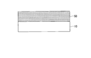
- FIG. 1 is a cross-sectional view schematically illustrating a hot stamping foil of an embodiment.
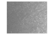
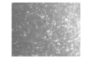
- the contact of the adhesive layer containing no particles with the carrier is schematically illustrated. It is a figure which shows typically the contact aspect of the contact bonding layer and carrier which contain only spacer particles. It is a figure which shows typically the contact aspect of the contact bonding layer containing a spacer particle and a powder filler, and a carrier. It is a conceptual diagram which shows the temperature change of a hot stamping foil. It is a photograph of the post-transfer laminated optical decorative body that does not cause white turbidity. It is a photograph of the post-transfer laminated optical decorative body causing white turbidity.
- FIG. 1 is a cross-sectional view schematically illustrating the hot stamping foil 1.
- the hot stamping foil holds the laminated optical decoration body 25 in a peelable manner.
- the hot stamping foil can transfer the laminated optical decoration body 25 to the transfer object by heat pressure.
- the hot stamping foil 1 includes a carrier 10 and a laminated optical decoration body 25 formed on the carrier 10.
- the carrier 10 and the laminated optical decoration body 25 are in contact with each other.
- the laminated optical decorative body 25 includes a laminated optical structure 20, a subduction control layer 30 formed on the laminated optical structure 20, and an adhesive layer 40 formed on the subduction control layer 30.
- the laminated optical structure 20 and the subsidence control layer 30 are in contact with each other or a covering layer is interposed therebetween.
- the sinking control layer 30 and the adhesive layer 40 are in contact with each other.
- the carrier 10 holds the laminated optical decoration body 25 until the hot stamping foil 1 is thermally transferred to the transfer target. After the hot stamping foil 1 is thermally transferred to the transfer target, it is peeled off at the boundary with the laminated optical structure 20. In other words, after the hot stamping foil 1 is thermally transferred to the transfer target, it is peeled off at the boundary with the laminated optical structure 20.
- the carrier 10 is a base film or a coated base film.
- the base film can be a single layer or a multilayer polymer film.
- the polymer film can be produced by an extrusion method, a solution casting method, or a calendar method. As the extrusion method, an inflation method or a T-die method can be applied.
- the polymer film can be a stretched or non-stretched film.
- the material of the polymer film can be a thermoplastic or a soluble resin.
- the thermoplastic can be a polyolefin or the like.
- the polyolefin may be PET (polyethylene terephthalate), PEN (polyethylene naphthalate), or PP (polypropylene).
- Polyolefin has moderate adhesiveness with the laminated optical structure 20.
- the polyolefin resin can hold the laminated optical structure 20 in a peelable manner.
- the base film can be a heat resistant film or a pressure resistant film. The heat-resistant material and pressure-resistant material can reduce deformation and alteration due to heat and pressure applied during transfer.
- the coated base film is coated on one side or both sides of the base film.
- This coat can be made by coating a resin alone or a resin containing powder. As this coating, a micro gravure coat, a gravure coat, a die coat, and a screen coat can be applied.
- the resin to be coated can be any one of acrylic resin, silicone resin, fluorine resin, any copolymer resin, any composite resin, and any composite resin of any copolymer resin.
- the powder contained in the resin can be silica powder, silicone powder, fluorine-based powder, or carbon powder.
- the thickness of the carrier 10 of the base film can be set to 4 ⁇ m or more, for example. When the thickness is less than 4 ⁇ m, the physical strength as a carrier becomes insufficient, and handling of the hot stamping foil becomes difficult.
- the thickness of the carrier 10 can be in the range of 12-50 ⁇ m.
- the base film can be paper, synthetic paper, plastic multilayer paper, or resin-impregnated paper depending on the application and purpose.
- the laminated optical structure 20 includes a top layer 21, a lacquer layer 22, and an inorganic deposition layer 23 in order from the carrier 10 side.
- the lacquer layer 22 is formed on the entire surface of the top layer 21, partially formed or omitted.
- the inorganic deposited layer 23 can be formed on the top layer 21.
- the inorganic deposition layer 23 can be formed on the lacquer layer 22.
- FIG. Although the basic configuration of the laminated optical structure 20 is well known, each layer will be described below.
- the top layer 21 supports the laminated optical structure 20 so as to be peelable from the carrier 10. After the transfer of the hot stamping foil 1, the top layer 21 of the laminated optical structure 20 is located on the opposite side of the transfer target and protects the laminated optical structure from external damage.
- the top layer 21 can be a layer containing a thermoplastic polymer and a surface modifier.
- the thermoplastic polymer of the top layer 21 can be a resin having a glass transition temperature of 90 ° C. or higher and 130 ° C.
- the thermoplastic polymer may be any composite of acrylic polymer, polyester, polyamide, polyimide, any copolymer, any composite, and any copolymer.
- the surface modifier can be a powder, wax, or oil. The powder can be heat resistant powder.
- the heat-resistant powder can be silica powder, polyethylene powder, fluorine-based powder, or silicone-based powder.
- the wax can be paraffin wax, silicone wax, or carnauba wax.
- the oil can be silicone oil.
- the top layer 21 may be colored. It can be colored by adding a pigment or dye to the resin of the top layer 21.
- the pigment can be an inorganic pigment, an organic pigment, or a mixture of an inorganic pigment and an organic pigment. Alternatively, the pigment may be a fluorescent pigment, a pearl pigment, a magnetic pigment alone, a blend of the same type, a mixture of different types, or a mixture of different types of the same blend.
- the dye can be a natural dye, a synthetic dye, or a mixture of a natural dye and a synthetic dye.
- the dye can be a fluorescent dye.
- the top layer 21 can be formed on the carrier 10 by printing and coating.
- the application may be gravure coating, micro gravure coating, or die coating.
- Printing can be gravure printing or screen printing.
- the thickness of the top layer 21 can be in the range of 0.5 ⁇ m to 5 ⁇ m.
- the top layer 21 can accept printing.
- Acrylic resin is easy to accept printing.
- a printed body with a laminated optical decorative body having a top layer capable of accepting printing is printable.
- the laminated optical decorative body-attached printed body having a top layer that can accept printing can be printed on both the laminated optical decorative body and the printed body.
- the lacquer layer 22 can have an uneven relief structure on one surface or both surfaces of the lacquer layer 22.
- the lacquer layer 22 may be an ultraviolet curable resin, a thermoplastic resin, or a thermosetting resin.
- the ultraviolet curable resin can be a monomer, oligomer, or polymer having an ethylenically unsaturated bond or an ethylenically unsaturated group, which is a cured resin.
- Examples of monomers having an ethylenically unsaturated bond or ethylenically unsaturated group include 1,6-hexanediol, neopentyl glycol diacrylate, trimethylolpropane triacrylate, pentaerythritol triacrylate, pentaerythritol tetraacrylate, and dipentaerythritol. Pentaacrylate and dipentaerythritol hexaacrylate can be used.
- the oligomer having an ethylenically unsaturated bond or ethylenically unsaturated group may be an epoxy acrylate, urethane acrylate, polyester acrylate oligomer or co-oligomer.
- the polymer may be a urethane-modified acrylic, epoxy-modified acrylic polymer or copolymer.
- UV curable resin acrylic resin, acrylic acrylate resin, epoxy acrylate resin, urethane acrylate resin, polyester acrylate resin, ethylene methacrylate resin, any copolymer resin, any composite resin, any copolymer Any composite resin can be used.
- the lacquer layer 21 may be colored. It can be colored by adding pigments and dyes to the resin of the lacquer layer 21.
- the pigment can be an inorganic pigment or an organic pigment. Alternatively, the pigment may be a fluorescent pigment, a pearl pigment, or a magnetic pigment.
- the dye can be a natural dye or a synthetic pigment. Alternatively, the dye can be a fluorescent dye.
- the thermoplastic resin of the lacquer layer 22 is any one of acrylic resin, epoxy resin, cellulose resin, vinyl resin, any copolymer resin, any composite resin, any copolymer resin. Composite resin.
- the thermosetting resin of the lacquer layer 22 is any one of urethane resin, melamine resin, epoxy resin, phenol resin, any copolymer resin, any composite resin, and any composite resin. It can be a resin.
- the thickness of the lacquer layer 22 can be in the range of 0.5 ⁇ m or more and 30 ⁇ m or less.
- the relief structure of the lacquer layer 22 has a concave portion or a convex portion, or a concave portion and a convex portion.
- the relief structure has optical properties such as optical diffraction, light reflection suppression, isotropic or anisotropic scattering effect, reflection, polarization selectivity, and wavelength selectivity.
- the optical effect of the relief structure can be detected by visual observation or mechanical detection.
- the optical properties of the relief structure are effective in preventing counterfeiting and tampering and improving design.
- the optical properties can be selected in combination with reliefs having one or more optical effects.
- the laminated optical structure 20 Due to the relief structure on the surface of the lacquer layer 22, the laminated optical structure 20 has diffraction, light reflection suppression, isotropic or anisotropic light scattering, refraction, polarization / wavelength selective reflection, transmission, light reflection suppression, etc.
- the optical function is provided.
- the laminated optical structure 20 can obtain the property of diffracting light by the relief structure.
- the pitch of the diffraction grating structure can be in the range of 0.5 ⁇ m to 2 ⁇ m.
- the depth of the diffraction grating structure may be in the range of 0.05 ⁇ m to 0.5 ⁇ m.
- the laminated optical structure 20 can obtain the light reflection suppressing property and the polarization / wavelength selective reflection, transmission, and light reflection suppression by the relief structure.
- the laminated optical structure 20 has isotropic or anisotropic scattered light.
- the relief structure provides the property of injecting.
- the average pitch of the scattering structure can be 0.5 ⁇ m or more and 3 ⁇ m or less.
- the depth may be 0.05 ⁇ m or more and 0.5 ⁇ m or less.
- the relief structure imparts the reflective property to the laminated optical structure 20 by providing the lacquer layer 22 with a region having a mirror structure and having a refractive index different from that of the adjacent layer.
- the average pitch of the mirror structure can be greater than 3 ⁇ m and 30 ⁇ m or less.
- the depth can be deeper than 0.5 ⁇ m and shallower than 20 ⁇ m.
- the optical properties of the laminated optical structure 20 can be perceived and detected by visual observation or mechanical detection. Thereby, the anti-counterfeiting performance and design properties can be improved.
- the relief structure on the surface of the lacquer layer 22 may have a plurality of relief structure regions.
- the relief structure region can display an image as a single unit or as a plurality of integrations.
- the image can be a picture, a photograph, a portrait, a landmark, a mark, a logo, a symbol alone or a combination thereof.
- the inorganic vapor deposition layer 23 has a function that makes it possible to easily observe the optical effect generated in the lacquer layer 22.
- the inorganic deposition layer 23 is formed on a part or the entire surface of the lacquer layer 22.
- advanced processing technology is required for manufacturing the laminated optical structure 20, and the hot stamping foil 1 has a higher counterfeit. It can have a preventive effect.
- the inorganic deposited layer 23 makes it possible to easily observe optical properties generated in the lacquer layer 22.
- the inorganic deposited layer 23 may display a structural color.
- the structural color is color development due to interference. Alternatively, the structural color changes depending on the observation angle and the illumination angle.
- the material of the inorganic deposited layer 23 can be a simple substance of metal or silicon, an alloy, or a compound thereof.
- the metal or silicon constituting the simple substance, the alloy, or these compounds can be any one or combination of Si, Al, Sn, Cr, Ni, Cu, and Ag.
- the thickness of the inorganic deposition layer 23 can be in the range of 10 to 500 nm.
- the inorganic deposition layer can be formed by depositing an inorganic material under reduced pressure.
- the inorganic deposition layer 23 can be deposited by vacuum evaporation, sputtering, or CVD.
- the inorganic deposition layer 23 is a single layer or a multilayer.
- the multi-layered inorganic deposition layer 23 can be formed by alternately laminating a single metal and a metal compound, alternately laminating dissimilar metals, or alternately laminating different metal compounds. .
- the inorganic deposition layer 23 in which a simple metal and a metal compound are alternately laminated is a multilayer in which a silicon dioxide layer is laminated on an aluminum layer.
- the coating layer 24 covers the entire surface or a part of the inorganic deposition layer 23.
- the coating layer 24 is provided as a resist on a part of the inorganic deposition layer 23, and the inorganic deposition layer 23 is selectively removed to remove the inorganic deposition layer 23 on the lacquer layer 22. Can be provided.
- the coating layer 24 may be provided corresponding to the inorganic deposition layer provided on a part.
- the inorganic deposition layer 23 can be coated with the coating layer 24 by printing, applying, and depositing the coating layer 24 on the inorganic deposition layer 23.
- a method of providing the coating layer 24 on a part of the inorganic deposition layer 23 a method of partially providing the coating layer 24 by printing, a coating layer 24 having different etching liquid permeability is deposited on the inorganic deposition layer 23, and the coating layer is formed.
- the coating layer 24 and the inorganic deposited layer 23 are selectively etched by the difference in the permeability of the etching solution, a resin material that is dissolved or hardly dissolved by ultraviolet exposure is applied, and ultraviolet rays are exposed in a pattern, and then the coating layer 24
- a method of selectively etching the inorganic deposited layer 23 with an etching solution, and forming a coating layer 24 after partially forming a soluble resin on the inorganic deposited layer 23 to form a soluble resin and a soluble resin A method of partially removing the upper coating layer with a solvent can be employed.
- Other known various processing techniques may be applied as long as the coating layer 24 is partially provided.
- the material of the coating layer 24 can be a resin, an inorganic material, or a composite of a resin and an inorganic material.
- the resin of the coating layer 24 can be a resin having etching resistance.
- the resin of the coating layer 24 can be a cured resin. The cured resin is easy to obtain etching resistance.
- the resin of the coating layer 24 is any one of vinyl resin, polystyrene resin, acrylic resin, polyurethane resin, polyamide resin, polyimide resin, any copolymer resin, any composite resin, any It can be any composite resin of copolymer resin.
- the vinyl resin can be vinyl chloride, polyvinylidene chloride, or polyvinyl alcohol.
- the polystyrene resin can be polystyrene-based polystyrene, styrene / acrylonitrile copolymer, polyethylene, or ethylene vinyl acetate copolymer.
- the acrylic resin can be polymethyl methacrylate.
- the resin which copolymerized at least 2 or more types among these may be sufficient.
- the molecule of the resin may contain an ester bond, a urethane bond, an ether bond, an amine bond, a silanol bond, and the like. You may bridge
- the curable resin may be a thermosetting resin such as a urethane resin or an epoxy resin, an ultraviolet curable resin such as an acrylate resin, or the like.
- the resin of the coating layer 24 may be other electron beam curable resin or moisture curable resin.
- the thickness of the coating layer 24 can be in the range of 0.1 ⁇ m to 5 ⁇ m.
- the sink control layer 30 adjusts the sink amount of spacer particles (described later) in the adhesive layer.
- the spacer particles hardly sink into the subsidence control layer, and maintain a gap between the adhesive layer and the carrier 10 when wound into a roll.
- the spacer particles 41 sink and moderately sink into the control layer.
- the sinking control layer 30 is in contact with the adhesive layer 40.
- the sinking control layer 30 contains a soft resin and a deformation limiting agent.
- the soft resin and the deformation limiting agent may have different flexibility.
- the mixing ratio of the soft resin and the deformation limiting agent can be in the range of 50: 1 to 1: 1. With the heat pressure, the soft resin in the sink control layer 30 is deformed and the spacer particles 41 sink.
- the deformation restricting agent suppresses deformation of the soft resin, and the spacer particles 41 are prevented from being excessively depressed, thereby adjusting the sinking of the spacer particles 41. Thereby, blocking due to excessive subsidence, and white turbidity defects of the laminated optical structure 20 due to the spacer particles 41 not submerging can be prevented. Since the subsidence control layer 30 has an appropriate hardness before hot pressing, the spacer particles 41 remain on the adhesive layer 40. In order to impart appropriate hardness to the subsidence control layer 30 before hot pressing, the soft resin is a crystalline resin, the deformation limiting agent is a high glass transition temperature polymer or a composite thereof, or the above-described configuration is combined be able to.
- the subsidence control layer 30 has an appropriate hardness.
- the deformation limiting agent is a high glass transition temperature polymer or a composite thereof, since the deformation limiting agent is in a glass state before hot pressing, the subsidence control layer 30 has an appropriate hardness.
- the glass transition temperature of the soft resin of the sink control layer 30 can be set to 80 ° C. or lower.
- the deformation limiting agent includes an inorganic powder filler having a particle size smaller than the thickness of the subsidence control layer 30, a high glass transition temperature polymer, an inorganic powder filler having a particle size smaller than the thickness of the adhesive layer, and a high glass transition temperature weight. Both can be combined.
- the glass transition point of the high glass transition temperature polymer can be 60 ° C. or higher or no glass transition point.
- the glass transition point of the high glass transition temperature polymer may be in the range of 60 ° C to 300 ° C.
- the high glass transition temperature polymer may be a polymer powder filler. When a high glass transition temperature polymer having a glass transition point of 60 ° C. or higher and a softening temperature of 90 ° C. or higher and 130 ° C.
- the high glass transition temperature polymer and the soft resin may have a two-phase phase separation structure.
- a phase separation structure in a two-phase state it can be obtained by applying a coating solution dissolved using a soft resin soluble in a solvent and a high glass transition temperature polymer.
- the high glass transition temperature polymer can be a continuous phase.
- the continuous phase forms a skeleton.
- the continuous phase is a porous structure or the like.
- the soft resin can be a dispersed phase or a continuous phase.
- the glass transition temperature of the high glass transition temperature polymer may be equal to or higher than the glass transition temperature of the soft resin.
- the high glass transition temperature polymer softens inside the outline of the thermal transfer area and does not soften outside the outline of the thermal transfer area, so the high glass transition temperature polymer of the outline of the thermal transfer area It is considered that the stress is concentrated on the resin and the resin is surely broken at the contour portion.
- the high glass transition temperature polymer may be mixed with the soft resin as a powder or dispersion.
- the soft resin may be a crystalline resin.
- High glass transition temperature polymer as a deformation inhibitor is vinyl chloride vinyl acetate copolymer, cellulose polymer, phenol polymer, fluorine polymer, silicone polymer, acrylic polymer, melamine polymer, epoxy polymer. be able to.
- the vinyl chloride vinyl acetate copolymer has good adhesion to other resins.
- the soft resin of the subsidence control layer 30 can be an acid-modified polyolefin resin.
- the acid-modified polyolefin resin may be a copolymer resin of ethylene and an acidic component.
- the ethylene / acidic copolymer may be ethylene (meth) acrylic acid copolymer resin (EMAA), ethylene-vinyl acetate copolymer resin, ethylene (meth) acrylic acid ester copolymer resin, or the like.
- a copolymer resin of ethylene and an acidic component is easy to obtain moderate flexibility and moderate adhesion with an adjacent layer.
- the acid-modified polyolefin resin can obtain adhesion with the adjacent inorganic vapor deposition layer, lacquer layer, and coating layer by acid modification. This is because the acid-modified polyolefin is bonded to the adjacent inorganic vapor-deposited layer and lacquer layer, and the organic silane compound and isocyanate of the coating layer.
- the soft resin in the subsidence control layer 30 can have a softening temperature lower than that of the vinyl chloride vinyl acetate copolymer in the subsidence control layer 30, and further has a softening temperature equal to or lower than the transfer temperature at the time of transfer. Can do.
- the softening temperature of the resin of the subsidence control layer 30 can be in the range of 60 ° C. or higher and 110 ° C. or lower. Since the transfer temperature (stamper plate surface temperature) of the hot stamping foil is generally in the range of 90 ° C. to 130 ° C., the softening temperature can be set to the above.
- the acid value of the acid-modified polyolefin can be measured by a commonly used FT-IR method or titration method. The acid value of the acid-modified polyolefin can be in the range of 0.5 to 200.
- a dispersion which is a dispersion of a soft resin may be used.
- the size of the dispersion particles can be about 30 ⁇ m.
- the soft resin and the vinyl chloride vinyl acetate copolymer may be different in flexibility. Usually, a soft resin is more flexible than a vinyl chloride vinyl acetate copolymer. The flexibility of each resin of the subduction control layer and the entire subduction control layer can be measured by a commonly used nano-intender.
- the softening temperature of the subsidence control layer 30 can be in the range of 60 ° C. or higher and 110 ° C. or lower.
- the softening temperature of the subsidence control layer 30 is a temperature at which the temperature at the time of transfer of the hot stamping foil is generally in the range of 90 ° C. to 130 ° C., and is softened at this transfer temperature.
- An auxiliary agent may be added to the subsidence control layer 30.
- the amount of auxiliary added can be in the range of 0.1 Wt% to 10 Wt%.
- a silane coupling agent or an isocyanate may be added.
- silane coupling agent By adding a silane coupling agent, even when a part of the subsidence control layer 30 is in contact with the inorganic vapor deposition layer 23 of the laminated optical structure 20, a silanol bond is generated to form a layer with the laminated optical structure 20. Adhesion stability is improved. Due to the silanol bond, the heat resistance and solvent resistance of the subduction control layer are also improved. Further, when a part of the subsidence control layer 30 is in contact with the lacquer layer 22 of the laminated optical structure 20, adhesion with the silane compound added to the lacquer layer 22 existing on the surface of the lacquer layer 22 is also improved. . Isocyanate may be added to the subduction control layer 30 as an auxiliary agent.
- the subduction control layer 30 may have fluorescence.
- the fluorescence can be realized by whether the resin or polymer has a fluorescent molecular structure, a fluorescent agent is added to the resin, or the resin or polymer has a fluorescent molecular structure and the fluorescent agent is added to the resin.
- the thickness of the subsidence control layer 30 can be in the range of 0.5 ⁇ m or more and 3 ⁇ m or less.
- the adhesive layer 40 includes a resin component that exhibits adhesion to the adherend, and spacer particles and a powder filler added to the resin component.
- a powder filler is not essential.
- the content ratio (weight ratio) of the powder filler in the adhesive layer 40 can be in the range of 0.1% to 100% of the resin component.
- As the resin component various known adhesives and pressure-sensitive adhesives can be used.
- An acrylic resin may be used as the resin component.
- the acrylic resin can be polymethyl methacrylate or the like.
- “short-time hot pressing” generally means hot pressing at 90 to 130 ° C. in less than 1 second. Therefore, as the resin component of the adhesive layer 40, a thermoplastic resin having a melting point between 60 ° C. and 130 ° C. other than the acrylic resin can be used. In this case, transfer can be performed by heat and pressure in a shorter time.
- thermoplastic resin other than the acrylic resin a vinyl resin, a polystyrene resin, a polyurethane resin, or the like can be used.
- the vinyl resin can be vinyl chloride, polyvinylidene chloride, polyvinyl alcohol, or the like.
- the polystyrene resin can be polystyrene, styrene / acrylonitrile copolymer, polyethylene, ethylene vinyl acetate copolymer, or the like, and may be a resin obtained by copolymerizing two or more of these.
- the resin may contain an ester bond, a urethane bond, an ether bond, an amine bond, a silanol bond, etc., and part of the chemical structure of two or more kinds of resins having functional groups related to these bonds. May be cross-linked. Molecular weight can be adjusted by these bonds, and softening temperature, viscoelasticity, solvent resistance, etc. can be adjusted.
- the thermoplastic resin may be a copolymer. Further, the thermoplastic resin may be modified.
- the adhesive layer 40 may have fluorescence. The fluorescence can be realized by whether the resin or polymer has a fluorescent molecular structure, a fluorescent agent is added to the resin, or the resin or polymer has a fluorescent molecular structure and the fluorescent agent is added to the resin.
- the thickness of the adhesive layer 40 defined by the resin component can be made thicker than the sinking control layer 30. The thickness of the adhesive layer 40 can be in the range of 2 ⁇ m or more and 10 ⁇ m or less.
- the spacer particles 41 have an average particle size larger than the thickness of the adhesive layer 40.
- the average particle diameter of the spacer particles 41 can be larger than the total thickness of the adhesive layer 40 and the subsidence control layer 30 and less than twice the total thickness.
- the average particle diameter of the spacer particles 41 can be in the range of 1 to 10 ⁇ m.
- the average particle diameter of the particles can be measured using a laser diffraction / scattering type particle size distribution measuring apparatus (such as manufactured by Microtrack BlueRaytrac Microtrack Bell Co., Ltd.) before application, Means diameter. If it is after application
- the spacer particles may be a blend of particles having two types of average particle sizes.
- the average particle diameter of the small spacer particles may be in the range of 1 to 10 ⁇ m, and the average particle diameter of the large spacer particles may be in the range of 10 ⁇ m to 30 ⁇ m.
- the volume ratio of the large spacer particles can be larger than the volume ratio of the small spacer particles.
- the volume ratio of the large spacer particle group to the small spacer particle group can be 1:50 or more and 1: 2 or less.
- the spacer particle 41 may be configured by blending two or more kinds of particle groups having an average particle diameter.
- the spacer particles 41 can be regular particles or irregular particles.
- the regular particles can be elliptical particles or spherical particles. Regular particles tend to maintain a stable gap.
- the spacer particles 41 can be inorganic, heat resistant resin, a composite of inorganic and heat resistant resin, or a natural material.
- the inorganic can be an inorganic compound or a pure substance.
- the inorganic compound can be silica, calcium carbonate, talc, barium sulfate, mica, aluminum hydroxide, magnesium hydroxide, kaolin clay, zeolite, mica and the like.
- the pure substance can be carbon black.
- the heat resistant resin as the material of the spacer particles 41 is a synthetic resin or the like.
- the synthetic resin can be an acrylic resin, a urethane resin, a polyethylene resin, a polypropylene resin, or the like.
- Natural materials can be wood flour, firewood, and the like.
- the inorganic and heat resistant resin composite of the spacer particles 41 can be made of the above-described materials of inorganic and heat resistant resin. Inorganic materials are easy to obtain heat resistance and chemical resistance. Synthetic resins are easy to obtain heat resistance and chemical resistance. Natural materials have a low environmental impact.
- the volume ratio of the spacer particles 41 to the resin component of the adhesive layer 40 can be in the range of 0.1% to 3%.
- the powder filler is a powder having an average particle size of nano level.
- silica various metals and oxides thereof can be used.
- the inorganic powder filler does not deteriorate with the solvent.
- the inorganic powder filler is low cost.
- the heat resistant resin powder filler is a powder having an average particle diameter of nano level.
- the heat resistant resin as the material of the heat resistant resin powder filler is a synthetic resin.
- the synthetic resin can be an acrylic resin, a urethane resin, a polyethylene resin, a polypropylene resin, or the like.
- the natural material can be cellulose, soot, zeolite, mica and the like. Synthetic resins are easy to obtain heat resistance and chemical resistance.
- the average particle diameter of the inorganic powder filler and the heat resistant resin powder filler can be 10 to 15 nanometers (nm).
- the average particle diameter of the inorganic powder filler and the heat resistant resin powder filler may be smaller than the film thickness of the adhesive layer 40.
- the average particle size of the nano-level filler in the present disclosure can be measured using a dynamic light scattering type particle size distribution measuring apparatus (such as Nanotrac Wave Microtrac Bell Co., Ltd.) before application, Mean average particle size. If it is after application
- the inorganic powder filler and the heat-resistant resin powder filler can be irregular particles.
- the thickness of the adhesive layer 40 is defined by the thickness of the resin component in the adhesive layer 40.
- the thickness of the adhesive layer 40 can be measured with a scanning electron microscope. Although the number of measurement points can be practically 5 points, it can be precisely 30 points, and the average value of measured actual values can be the thickness. Or you may measure similarly with an optical microscope.
- the thickness of the other layers of the hot stamping foil 1 can also be measured with a scanning electron microscope. The number of measurement points at this time can be practically 5 points, but can be precisely 30 points, and the average value of the measured actual values can be the thickness. Moreover, you may measure with an optical microscope similarly.
- the adhesive layer 40 may contain a polymer having a glass transition point of 60 ° C. or higher in addition to the thermoplastic resin, spacer particles, and powder filler.
- the glass transition point of the polymer can be 60 ° C. or higher and 150 ° C. or lower.
- the polymer one type of resin may be used, or a mixture of a plurality of resins may be used.
- a thermoplastic resin or a cured resin can be used.
- the polymer can be a polymer of one kind of monomer or a copolymer.
- acrylic, polyurethane, polyvinyl chloride, polyvinyl acetate, polystyrene or the like can be used.
- the copolymer vinyl chloride vinyl acetate copolymer or the like can be used.
- the polymer may contain a low molecular weight polymer such as a terpene resin, a rosin resin, or styrene maleic acid.
- the ratio of the thermoplastic resin of the resin component to the polymer having a glass transition point of 60 ° C. or higher can be in the range of 50: 1 to 5: 1, and further can be in the range of 40: 1 to 6: 1.
- the adhesive layer 40 may contain breakage promoting particles.
- the fracture accelerating particles are formed at the boundary between the transfer region and other regions when the transfer body including the laminated optical structure 20, the sink control layer 30, and the adhesive layer 40 is thermally transferred from the hot stamping foil 1 to the transfer target. Ensure that the transfer body breaks. When the transfer body is stretched and stretched out of the transfer region due to insufficient breakage, resin scraps are generated from the stretched portion.
- the breakage promoting particles particles having the same material, the same shape, and the same CV value as the spacer particles can be used, and particles having a particle diameter smaller than the combined thickness of the adhesive layer and the subsidence control layer can be used.
- the adhesive layer 40 can be formed by applying a coating liquid containing a resin component and spacer particles.
- the coating liquid may have a solid content completely dissolved, or may have a solid content dispersed like a dispersion or an emulsion.
- Application may be roll coating, reverse roll coating, gravure coating, reverse gravure coating, bar coating, rod coating, lip coating, die coating, and the like.
- Printing may also be applied to the application. Printing can be gravure or screen printing.
- the coating liquid is preferably dried at a temperature below the melting point of the solid content.
- the transfer target can be a printed body.
- the printed body is a film printed on the entire surface or a part thereof, a printed paper, a film to be printed, or a printing paper.
- the thickness of the printed body can be in the range of 0.05 mm or more and 4 mm or less.
- the printed film is a base film and an anchor layer coated on the entire surface or a part of the surface of the base film and printed on the coated anchor layer.
- the printed paper is printed on high-quality paper, medium-quality paper, coated paper, uncoated paper, film-laminated paper, resin-impregnated paper, or the like.
- the film to be printed is a plastic film with an anchor layer coated on the base film to accept printing. A plastic film can be applied to the printed film and the base film of the printed film.
- the plastic film can be a stretched film or an unstretched film.
- the stretched film or the unstretched film film can be a polyester film, a polycarbonate film, a polyethylene film, or a polypropylene film.
- the polymer film can be a single layer or a multilayer in which the same material or different materials are alternately laminated.
- the printing can be gravure printing, offset printing, screen printing, or the like.
- Printing can be ink printed.
- the ink can be a pigment ink, a dye ink, a pearl ink, or an invisible ink.
- Invisible ink can be fluorescent ink or infrared absorbing ink.
- the print object to be transferred can be security printing.
- Security printing can be banknotes, tickets, tags, stickers, game cards, authentication cards, authentication pages, gift certificates, certificates, posters, greeting cards, business cards, and the like.
- Security printing includes anti-counterfeiting measures such as counterfeiting, falsification, and theft of information that should be kept secret, measures that make it easy to determine the presence or absence of fraud, and anti-counterfeiting measures. It is printing required.
- the anchor layer used for the printable polymer film or the printed polymer film can be a thermoplastic resin, a thermosetting resin, or a thermoplastic thermosetting resin.
- the resin of the anchor layer can be a polymer or a copolymer.
- the polymer or copolymer of the anchor layer can be polyethylene, ethylene methacrylic acid, polyethyleneimine, or polyurethane.
- the + polar group or ⁇ polar group of polyethyleneimine brings about high adhesiveness with the laminated optical decoration body 25 by bonding with the + polar group or ⁇ polar group of the ethylene (meth) acrylic acid copolymer.
- the surface of the transfer target can be modified by a known surface modification treatment.
- the surface modification treatment of the transfer target provides high adhesion with the hot stamping foil 1.
- the surface modification treatment can be corona discharge treatment, flame treatment, ozone treatment, ultraviolet treatment, radiation treatment, roughening treatment, chemical treatment, plasma treatment, low temperature plasma treatment, and grafting treatment.
- the transfer object has high adhesiveness with the hot stamping foil 1.
- the hot stamping foil 1 is transferred so that the adhesive layer 40 is in contact with the transfer target, and after the transfer, the carrier 10 is peeled off.
- the laminated optical structure, or the printing object to be transferred, both the laminated optical structure and the printing object to be transferred can be printed.
- printing can be performed on the laminated optical structure or on the transfer target print body on both the multilayer optical structure and the transfer target print body.
- the laminated optical structure can be thermally transferred to the printed body to obtain a printed body with the laminated optical structure.
- FIG. 10 and FIG. 11 show examples of a printed body with a laminated optical decorative body.
- a printed body 100 with a laminated optical decorative body shown in a plan view in FIG. 10 is a laminated optical decorative body 25 of a banknote (printed body) 101 to be transferred, to which printing 101 a is applied, and a hot stamping foil 1 transferred to the banknote 101.
- the banknote 101 is transferred with two types of laminated optical decoration bodies, that is, a patch-shaped laminated optical decoration body 25A and a stripe-shaped laminated optical decoration body 25B. It's okay.
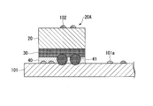
- FIG. 11 is a partial schematic cross-sectional view of FIG.
- the laminated optical decoration body 25 ⁇ / b> A is joined to the banknote 101 by the adhesive layer 40.
- the spacer particles 41 in the adhesive layer 40 are submerged in the subsidence control layer 30.
- a print 102 is formed on the lower surface of the adhesive layer 40 and the upper surface of the laminated optical decoration body 25A.
- the laminated optical decorative body can be printed on either side.
- the hot stamping foil 1 When the hot stamping foil 1 is industrially mass-produced, the laminated optical structure 20, the anchor layer 30, and the adhesive layer 40 are formed on the long carrier 10, so that the hot stamping is performed with the carrier 10 connected.
- the foil 1 is manufactured.
- the hot stamping foil 1 manufactured in this way is usually wound and stored in a roll until it is transferred to a transfer target.
- Blocking is a problem that occurs during storage of hot stamping foil.
- Blocking is a phenomenon in which hot stamping foils stick to each other during storage.
- the hot stamping foil wound in a roll is fed out, the top layer is peeled off from the carrier and the laminated optical structure A part or all of them remain on the carrier located on the lower side (the part wound inside). As a result, the hot stamping foil in which blocking has occurred becomes defective.
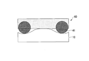
- the hot stamping foil 1 of the present embodiment blocking can be suppressed by mixing spacer particles in the adhesive layer 40. Details will be described below. As shown in FIG. 2, the adhesive layer 50 that does not contain spacer particles is likely to be blocked because the adhesive resin component contacts the lower carrier 10 over the entire surface. When spacer particles having a particle size larger than the thickness of the resin component are put in the adhesive layer, a part of the spacer particles protrudes on the adhesive layer, so that the contact area between the resin component of the adhesive layer and the carrier 10 decreases.
- FIG. 3 shows an adhesive layer 60 containing only the spacer particles 41.
- FIG. 4 shows an adhesive layer 40 of this embodiment containing spacer particles 41 and powder fillers 42.
- the particle size of the powder filler 42 is smaller than the thickness of the adhesive layer 40, the powder filler 42 is present in a larger amount than the spacer particles 41.
- the hot stamping foil 1 of this embodiment can suppress generation
- the weight ratio of the spacer particles to the powder filler is preferably 1:20 to 1: 100, and more preferably 1:30 to 1:50.
- Another problem that occurs in the hot stamping foil 1 is cloudiness. As described above, white turbidity is generated when irregularities are generated on the surface of the laminated optical structure 20 and light hitting the laminated optical structure 20 is scattered. The spacer particles added to the adhesive layer can cause unevenness on the surface of the laminated optical structure 20.
- a vinyl chloride-vinyl acetate copolymer having good adhesion to both resins and inorganic materials has been used.
- the vinyl chloride vinyl acetate copolymer is a resin having poor flexibility
- the spacer particles may break through the anchor layer at the time of transfer in combination with the adhesive layer to which the spacer particles are added. When the hard spacer particles penetrating the anchor layer deform the laminated optical structure, the surface of the laminated optical structure 20 becomes uneven, which causes white turbidity.
- the layer corresponding to the conventional anchor layer has some flexibility, but if it is too flexible, the spacer particles are excessively embedded in the anchor layer. , Blocking effect cannot be fully exhibited.
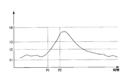
- FIG. 5 shows a conceptual diagram of a temperature change in the hot stamping foil 1. During storage of the temperature t from t1 to t2 shown in FIG. 5, since neither the soft resin nor the deformation inhibitor is softened, the spacer particles 41 prevent blocking appropriately.
- the temperature of the hot stamping foil 1 rapidly rises to a temperature close to the transfer temperature t4 in about 1 second until the time P2 when the transfer ends.
- the soft resin is softened, but the deformation inhibitor is not softened.
- the deformation suppressing agent is softened, and the spacer particles 41 are sunk into the control layer 30.
- the movement of the spacer particles 41 sinks, and the control layer 30 suitably absorbs and suitably prevents the occurrence of white turbidity.
- the subsidence control layer 30 hardly deforms even when pressed by the spacer particles. There is no sinking inside. As a result, the protruding amount of the spacer particles 41 from the resin component hardly changes before and after the heat pressure load. Since the maximum dimension in the thickness direction of the adhesive layer 40 is defined solely by the protruding amount of the spacer particles, in this case, the total thickness of the hot stamping foil hardly changes before and after the heat pressure load.
- the subsidence control layer 30 when the subsidence control layer 30 is sufficiently flexible during hot pressing, a part of the subsidence control layer 30 is pushed by the spacer particles 41 to be deformed, and a part of the spacer particles 41 is subsidized. Sink into 30.
- the protruding amount of the spacer particles 41 from the resin component after the heat and pressure load decreases according to the amount of sinking.
- the total thickness of the hot stamping foil also decreases after the hot pressure load. Therefore, by measuring the difference in the total thickness of the hot stamping foil before and after hot pressing, it is possible to specify the amount of sinking of the spacer particles during hot pressing.
- blocking effect and white turbidity prevention can be achieved by setting the amount of sinking of the spacer particle at the time of transfer hot pressure to 20% to 60% of the amount of sinking of the spacer particle at the time of overloading hot pressure. It was confirmed that the effects can be maximized. This is a new finding discovered by the inventor for the first time.
- the powder filler is not necessarily essential, and the adhesive layer may be configured to contain only spacer particles.
- the hot-pressing conditions for measuring the amount of filler sinking simulated the conditions in the warehouse during storage, temperature 40 ° C.
- the hot pressure condition is set within a range of a load of ⁇ 4 kg, and in particular, the evaluation can be performed with a 2 kg load at 60 ° C. This is set in consideration of the most severe conditions during storage.
- the hot stamping foil 1 can realize both the prevention of blocking and the prevention of white turbidity, which has been difficult in the past, by the configuration of the sinking control layer 30 and the adhesive layer 40.
- the hot stamping foil of the present embodiment will be further described using examples and comparative examples. However, the technical scope of the present invention is not limited by the specific contents of these examples.
- a method for producing a hot stamping foil is described below.
- the top layer forming ink was applied and dried on one surface of the carrier so that the film thickness after drying (dry film thickness) was 1 ⁇ m, thereby forming a top layer.
- the lacquer layer forming ink was applied and dried on the top layer so that the dry film thickness was 1 ⁇ m, and then a relief structure constituting a diffraction grating was formed on the surface of the lacquer layer by a roll embossing method.
- aluminum was vacuum-deposited to a thickness of 50 nm to form an inorganic deposition layer.
- the coating layer forming ink was applied and dried on the inorganic deposition layer so that the dry film thickness became 1 ⁇ m, thereby forming a coating layer.
- a laminated optical structure was formed on the carrier.
- the anchor layer forming ink A was applied and dried on the laminated optical structure so that the dry film thickness was 1 to 2 ⁇ m to form an anchor layer.
- the adhesive layer forming ink A was applied and dried on the anchor layer so that the dry film thickness of the solid content was 4 to 5 ⁇ m to form an adhesive layer.
- the hot stamping foil of Example 1 was produced.
- Example 2 A hot stamping foil of Example 2 was produced in the same manner as in Example 1 except that the following ink B for sinking control layer formation was used instead of the ink A for sinking control layer formation.
- (Sink control layer forming ink B) Polyester urethane resin (UR-8200 tg 73 ° C, manufactured by Toyobo Co., Ltd.) 31 parts Vinyl chloride vinyl acetate copolymer (E15 / 45M) 13.8 parts Methyl ethyl ketone 27.6 parts Toluene 27.6 parts
- Example 3 A hot stamping foil of Example 3 was produced in the same manner as in Example 1 except that the following ink C for forming subsidence control layer was used instead of ink A for forming subsidence control layer.
- ink control layer forming ink C Polyester urethane resin (UR-8300 tg, 23 ° C, manufactured by Toyobo Co., Ltd.) 31 parts Vinyl chloride vinyl acetate copolymer (E15 / 45M) 13.8 parts Methyl ethyl ketone 27.6 parts Toluene 27.6 parts
- Example 4 A hot stamping foil of Example 4 was produced in the same manner as in Example 1 except that the following ink D for formation control layer was used instead of ink A for formation control layer.
- Ink D for sinking control layer formation Polyester urethane resin (UR-8700 tg 22 ° C, manufactured by Toyobo Co., Ltd.) 31 parts Vinyl chloride vinyl acetate copolymer (E15 / 45M) 13.8 parts Methyl ethyl ketone 27.6 parts Toluene 27.6 parts
- Example 5 A hot stamping foil of Example 5 was produced in the same manner as in Example 1 except that the following ink E for forming a control layer was used instead of ink A for forming a control layer.
- ink control layer forming ink E EMAA (Dispersion (average particle size 30 ⁇ m), softening point 62 ° C.) 57 parts Vinyl chloride vinyl acetate copolymer (E15 / 45M) 8.6 parts Methyl ethyl ketone 17.2 parts Toluene 17.2 parts
- Example 6 A hot stamping foil of Example 6 was produced in the same manner as in Example 1 except that the following ink F for forming a control layer was used instead of ink A for forming a control layer.
- ink F for sinking control layer formation Crystalline polyester (dispersion, Tg ⁇ 14 ° C.) 40 parts Vinyl chloride vinyl acetate copolymer (E15 / 45M) 12 parts Methyl ethyl ketone 24 parts Toluene 24 parts
- Example 7 A hot stamping foil of Example 7 was produced in the same manner as in Example 1 except that the following ink G for formation of a control layer was used instead of ink A for formation of a control layer.
- ink control layer forming ink G Polyamide-based elastomer (softening temperature 142 ⁇ 5 ° C) 8 parts Vinyl chloride vinyl acetate copolymer (E15 / 45M) 12 parts Methyl ethyl ketone 40 parts Toluene 40 parts
- Example 8 A hot stamping foil of Example 8 was produced in the same manner as in Example 1 except that the following ink H for formation of a control layer was used instead of ink A for formation of a control layer.
- ink control layer forming ink H Polyamide elastomer (TPAE-12 manufactured by T & K TOKA) 8 parts Vinyl chloride vinyl acetate copolymer (E15 / 45M) 12 parts Methyl ethyl ketone 40 parts Toluene 40 parts
- Example 9 A hot stamping foil of Example 9 was produced in the same manner as in Example 1 except that the following ink I for forming control layer was used instead of ink A for forming control layer.
- ink control layer forming ink E Polyamide-based elastomer (TPAE-31, melting point 114 ° C., manufactured by T & K TOKA) 5.7 parts Vinyl chloride / vinyl acetate copolymer (E15 / 45M) 8.6 parts Methyl ethyl ketone 17.2 parts Toluene 42.85 parts Ethanol 25.65 parts
- Example 10 A hot stamping foil of Example 10 was produced in the same manner as in Example 1 except that the following ink J for forming a control layer was used instead of ink A for forming a control layer.
- ink J for forming subsidence control layer EMAA (dispersion, softening temperature 62 ° C.) 57 parts Cellulose acetate propionate (CAP-504-0.2 tg 159 ° C. manufactured by Eastman Chemical Co.) 8.6 parts Ethanol 17.2 parts Toluene 17.2 parts
- Example 11 A hot stamping foil of Example 11 was produced in the same manner as in Example 1 except that the following ink K for sinking control layer formation was used instead of the ink A for sinking control layer formation.
- Ink K for sinking control layer formation EMAA (dispersion, softening temperature 62 ° C.) 57 parts Terpene phenol resin (YS Polystar T160, softening point 160 ⁇ 5 ° C., manufactured by Yasuhara Chemical Co., Ltd.) 8.6 parts Methyl ethyl ketone 34.4 parts
- Example 12 A hot stamping foil of Example 12 was produced in the same manner as in Example 1 except that the following ink L for sinking control layer was used instead of the ink A for forming sinking control layer.
- (Sink control layer forming ink L) Acrylic resin (BPS6458 tg -37 ° C manufactured by Toyo Ink Co., Ltd.) 61.6 parts Vinyl chloride vinyl acetate copolymer (Solvine A tg 76 ° C manufactured by Nissin Chemical Industry Co., Ltd.) 3.1 parts Silica filler (Silo manufactured by Fuji Silysia Chemical Ltd.) Hovic 100) 4.6 parts Methyl ethyl ketone 20.7 parts Toluene 10.0 parts
- Example 13 A hot stamping foil of Example 13 was produced in the same manner as in Example 1 except that the following adhesive layer forming ink B was used instead of the adhesive layer forming ink A.
- Adhesive layer forming ink B Ethylene (meth) acrylic acid copolymer dispersion solution (Mitsui / DuPont Polychemical Nucrel AN4213C Melting point 88 ° C.
- Example 14 A hot stamping foil of Example 14 was produced in the same manner as in Example 1 except that the following adhesive layer forming ink C was used instead of the adhesive layer forming ink A.
- Acrylic resin 26.9 parts Polyester resin 0.7 parts Antifoam agent 0.1 part Silica 0.8 part Nano silica 23.5 parts Methyl ethyl ketone 6.9 parts
- Ethylene (meth) acrylic acid copolymer Dispersion Solution (Mitsui / DuPont Polychemical Nucrel AN4213C Melting point 88 ° C Dispersion solvent Toluene / ethyl acetate) 40 parts
- Comparative Example 1 A hot stamping foil of Comparative Example 2 was produced in the same manner as in Example 1 except that the following ink O for forming control layer was used instead of ink A for forming control layer.
- (Sink control layer forming ink O) Vinyl chloride vinyl acetate copolymer (E15 / 45M) 20 parts Methyl ethyl ketone 40 parts Toluene 40 parts
- Comparative Example 2 A hot stamping foil of Comparative Example 3 was produced in the same manner as in Example 1 except that the following ink P for forming a control layer was used instead of ink A for forming a control layer.
- Ink P for sinking control layer formation Vinyl chloride vinyl acetate copolymer (Sorvine A) 20 parts Methyl ethyl ketone 40 parts Toluene 40 parts
- the hot stamping foil of each example the following items were evaluated. (Measurement of spacer particle sinking amount during hot pressing) Eight hot stamping foils were stacked, and both sides in the thickness direction were sandwiched between PET sheets. In this state, hot pressure was applied for 20 minutes under the conditions of 2 kgf / cm 2 and 60 ° C. (using a heat seal tester TP-701C manufactured by Tester Sangyo). The total thickness of the hot stamping foil before and after hot pressing was measured at 5 randomly set locations, and the amount of subsidence was calculated by the following method. Reduction of film thickness when 8 samples of hot stamping foil are stacked and the same sample as above sandwiched between PET is subjected to hot pressure for 60 seconds under conditions of 115 ° C.
- Hot stamping foils of each example cut to a length of 100 mm and a width of 24 mm were arranged in the length direction on the outer peripheral surface of a roll-shaped PET wound 100 m, and a total of 100 m hot stamping foil was wound. This was stored at 60 ° C. for 24 hours, and further stored at room temperature for 12 hours, and then the hot stamping foil was taken out. Hot stamping foils stacked in the thickness direction were sequentially separated and evaluated in the following two stages. ⁇ (good): The laminated optical structure is not observed to be attached to the carrier of the lower hot stamping foil. X (bad): At least a part of the laminated optical structure is attached to the carrier of the lower hot stamping foil. Sticky items are allowed
- the hot stamping foil of each example was transferred under the conditions of a plate surface temperature of 115 ° C., a pressure of 1.05 t / cm 2, and a pressurization time of 0.3 seconds. Thereafter, the reflection density (absolute density, color channel K) of the surface of the laminated optical structure transferred using a reflection densitometer (RD918, manufactured by Macbeth, measurement area ⁇ 2 mm) was measured. Evaluation was made in the following two stages.
- the transfer thermal pressure of the spacer particles with respect to the subsidence amount at the time of overloading the spacer particles without using a vinyl chloride vinyl acetate copolymer in the subsidence control layer was shown that by making the amount of sinking at 20% or more and 60% or less, it is possible to achieve both blocking prevention and suppression of white turbidity during transfer.
- the subsidence control layer contains a high glass transition temperature polymer deformation limiting agent having a glass transition point of 110 ° C. or less.
- the hot stamping foil has a ribbon shape, and the roll width w1 is 20 mm.
- the laminated optical structure 20 to be transferred to the transfer object has an elliptical patch shape with a major axis of 15 mm and a minor axis of 12 mm.
- the interval p1 between the laminated optical structures 20 to be transferred is 3 mm.
- the area ratio of the laminated optical structure in the hot stamping foil of unit length u1 (15 mm) is 30 to 40%.
- Example 2-1 A hot stamping foil of Example 2-1 was produced in the same manner as in Example 1 except that the following ink BA for forming a control layer was used instead of ink A for forming a control layer.
- ink BA for sinking control layer formation Soft resin: Acrylic resin (tg -46 ° C) 63.0 parts
- Deformation limiting agent Vinyl chloride vinyl acetate copolymer (Solvine A tg 76 ° C) 2.0 parts silica filler (Silo Hovic 100 manufactured by Fuji Silysia Chemical Ltd.) 4.3 parts methyl ethyl ketone 20.7 parts toluene 10 parts
- Example 2-2 A hot stamping foil of Example 2-3 was produced in the same manner as in Example 2-1, except that the following sink control layer forming ink BC was used instead of the sink control layer forming ink BA. .
- (Sink control layer forming ink BC) Acrylic resin (tg -46 ° C) 64.0 parts Vinyl chloride vinyl acetate copolymer (Solvine A tg 76 ° C) 1.9 parts Silica filler (Silo Hovic 100 manufactured by Fuji Silysia Chemical Ltd.) 3.4 parts methyl ethyl ketone 20.7 parts toluene 10 parts
- Example 2-3 A hot stamping foil of Example 2-4 was produced in the same manner as in Example 2-1, except that the following sink control layer forming ink BD was used instead of the sink control layer forming ink BA. .
- Ink BD for sinking control layer formation Acrylic resin (tg -46 ° C) 62.5 parts Vinyl chloride vinyl acetate copolymer (Solvine A tg 76 ° C) 3.2 parts Silica filler (Silo Hovic 100 manufactured by Fuji Silysia Chemical Ltd.) 3.6 parts methyl ethyl ketone 20.7 parts toluene 10 parts
- Example 2-4 A hot stamping foil of Example 2-5 was produced in the same manner as in Example 2-1, except that the following sink control layer forming ink BE was used instead of the sink control layer forming ink BA. .
- (Sink control layer forming ink BE) Acrylic resin (tg -46 ° C) 63.3 parts Vinyl chloride vinyl acetate copolymer (Solvine A tg 76 ° C) 3.1 parts Silica filler (Silo Hovic 100 manufactured by Fuji Silysia Chemical Ltd.) 2.9 parts Methyl ethyl ketone 20.7 parts Toluene 10 parts
- Example 2-5 A hot stamping foil of Example 2-6 was produced in the same manner as in Example 2-1, except that the following sink control layer forming ink BF was used instead of the sink control layer forming ink BA. .
- Ink BF for sinking control layer formation Acrylic resin (tg -46 ° C) 63.6 parts Vinyl chloride vinyl acetate copolymer (Sorvain A tg 76 ° C) 3.2 parts Silica filler (Silo Hovic 100 manufactured by Fuji Silysia Chemical Ltd.) 2.5 parts methyl ethyl ketone 20.7 parts toluene 10 parts
- Example 2-6 A hot stamping foil of Example 2-7 was produced in the same manner as in Example 2-1, except that the following ink BG for formation control layer was used instead of the ink BA for formation control layer. .
- Ink BG for sinking control layer formation Acrylic resin (tg -46 ° C) 64.3 parts Vinyl chloride vinyl acetate copolymer (Solvine A tg 76 ° C) 3.1 parts Silica filler (Silo Hovic 100 manufactured by Fuji Silysia Chemical Ltd.) 1.9 parts methyl ethyl ketone 20.7 parts toluene 10 parts
- Example 2--7 A hot stamping foil of Example 2-8 was produced in the same manner as in Example 2-1, except that the following sink control layer forming ink BH was used instead of the sink control layer forming ink BA. .
- (Sink control layer forming ink BH) Acrylic resin (tg ⁇ 37 ° C.) 64.3 parts Vinyl chloride vinyl acetate copolymer (Solvine A tg 76 ° C.) 3.1 parts Silica filler (Silo Hovic 100 manufactured by Fuji Silysia Chemical Ltd.) 1.9 parts methyl ethyl ketone 20.7 parts toluene 10 parts
- Example 2-8 A hot stamping foil of Example 2-9 was produced in the same manner as in Example 2-1, except that the following sink control layer forming ink BI was used instead of the sink control layer forming ink BA. .
- (Sink control layer forming ink BI) Acrylic resin (tg 20 ° C.) 64.3 parts Vinyl chloride vinyl acetate copolymer (Sorvain A tg 76 ° C.) 3.1 parts Silica filler (Silo Hovic 100 manufactured by Fuji Silysia Chemical Ltd.) 1.9 parts methyl ethyl ketone 20.7 parts toluene 10 parts
- the transfer quality and white turbidity generated in the laminated optical structure were evaluated.
- the cloudiness was evaluated by the same procedure as in the first group (Examples 1 to 14 and Comparative Examples 1 to 3).
- the transfer quality was evaluated as follows. (Transfer quality) A high-quality paper having a thickness of about 200 ⁇ m was used as a transfer target.
- the hot stamping foil and the object to be transferred were cut into a width of 20 mm and a length of 200 mm, and transferred at intervals of 30 mm in the length direction under conditions of a plate surface temperature of 115 ° C., a pressure of 1.05 t / cm 2 , and a pressurization time of 0.3 seconds.
- Tensilon STA1225 (manufactured by ORIENTEC) was used to pull in the 90 ° direction at 1 kN 100% and 1000 mm / min, and the length of the burr portion generated around the laminated optical structure was measured. Evaluation was made in the following two stages. ⁇ (good): length of burr portion 5 mm or less ⁇ (bad): length of burr portion 5 mm or more The results are shown in Table 2. Although not shown in Table 2, the hot stamping foils according to the examples of the second group were all appropriately prevented from blocking.
- flat hot stamping When transferring a laminated optical decorative body partially formed by hot stamping to a transfer target, flat hot stamping is generally employed, and burrs are likely to occur at the periphery of the transfer region during hot stamping. Further, in flat hot stamping, the heat pressure is concentrated on the transfer area, so the pressure applied to the transfer area tends to increase, and white turbidity tends to occur.
- both the transfer quality and the white turbidity suppression were good.
- the deformation limiting agent of the subsidence control layer is a high glass transition temperature polymer having a softening temperature of 90 ° C. or higher and 130 ° C. or lower
- the high glass transition temperature polymer is softened inside the transfer region during hot stamping, resulting in high elasticity.
- the high glass transition temperature polymer does not soften, so the elasticity remains low. Therefore, when the carrier is peeled off in the final step of hot stamping and only the laminated optical structure in the transfer region is transferred, stress concentrates on the high glass transition temperature polymer at the boundary of the transfer region of the subsidence control layer. It is considered that the boundary of the transfer region of the subsidence control layer was surely broken and the burr at the time of transfer was suppressed.
- the deformation control agent of the subsidence control layer is a high glass transition temperature polymer
- the deformation control agent in the transfer region is also softened during hot stamping, thereby concentrating on the spacer particles of the adhesive layer in the transfer region. It is considered that the pressure was submerged and the control layer suitably absorbed and white turbidity was prevented.
- the soft resin of the sinking control layer is a crystalline resin.
- the mode of hot stamping foil in the following examples and comparative examples is shown in FIG.
- the width w1 of the hot stamping foil roll is 8 mm.
- the laminated optical structure 20 transferred to the transfer object is a rectangle having a short side of 8 mm and a long side of 60 mm, and the laminated optical structure 20 is formed over the width direction of the hot stamping foil.
- the interval p2 between the laminated optical structures 20 to be transferred is 15 mm.
- the area ratio of the laminated optical structure in the hot stamping foil having a unit length u2 (75 mm) is 80%.
- Example 3-1 In the same manner as in Example 1, except that the following sink control layer forming ink CA and adhesive layer forming ink CA were used instead of the sink control layer forming ink A and the adhesive layer forming ink A. A hot stamping foil of Example 3-1 was produced.
- Example 3-2 A hot stamping foil of Example 3-2 was produced in the same manner as in Example 3-1, except that the following sink control layer forming ink CB was used instead of the sink control layer forming ink CA. .
- (Sink control layer forming ink CB) Crystalline polyester (soft resin (melting point 100 ° C.), dispersion solution) 66.7 parts Vinyl chloride vinyl acetate copolymer 2.7 parts Silica filler (Silo Hovic 100 manufactured by Fuji Silysia Chemical Ltd.) 2.0 parts methyl ethyl ketone 28.6 parts
- Example 3-3 A hot stamping foil of Example 3-3 was produced in the same manner as in Example 3-1, except that the following sink control layer forming ink CC was used instead of the sink control layer forming ink CA. .
- Ink CC for sinking control layer formation Crystalline polyester (soft resin (melting point 100 ° C.), dispersion solution) 76.9 parts silica filler (Silo Hovic 100 manufactured by Fuji Silysia Chemical Ltd.) 2.3 parts methyl ethyl ketone 20.8 parts
- Example 3-4 A hot stamping foil of Example 3-4 was produced in the same manner as in Example 3-1, except that the following ink CD for forming the control layer was used instead of the ink CA for forming the control layer. .
- Ink CD for sinking control layer formation Crystalline polyester (soft resin (melting point 100 ° C.), dispersion solution) 62.4 parts silica filler (Silo Hovic 100 manufactured by Fuji Silysia Chemical Ltd.) 3.8 parts methyl ethyl ketone 33.8 parts
- Example 3-5 A hot stamping foil of Example 3-5 was produced in the same manner as in Example 3-1, except that the following ink CE for forming a control layer was used instead of the ink CA for forming a control layer. .
- ink CE for sinking control layer formation Crystalline polyester (soft resin (melting point 107 ° C), dispersion solution) 60.4 parts silica filler (Silo Hovic 100 manufactured by Fuji Silysia Chemical Ltd.) 5.8 parts Methyl ethyl ketone 33.8 parts
- Example 3-6 A hot stamping foil of Example 3-6 was prepared in the same manner as in Example 3-1, except that the following sink control layer forming ink CF was used instead of the sink control layer forming ink CA. .
- (Sink control layer forming ink CF) Crystalline polyester (soft resin (melting point 111 ° C.), dispersion solution) 62.4 parts silica filler (Silo Hovic 100 manufactured by Fuji Silysia Chemical Ltd.) 3.8 parts methyl ethyl ketone 33.8 parts
- Example 3--7 A hot stamping foil of Example 3-7 was produced in the same manner as in Example 3-1, except that the following adhesive layer forming ink CB was used instead of the adhesive layer forming ink CA.
- Adhesive layer forming ink CB Acrylic resin (resin component) 49.2 parts Polyester resin (resin component) 1.3 parts Antifoaming agent 0.3 part Silica (breaking accelerating particles, average particle size 3.4 to 5.5 ⁇ m, aspect ratio 30 to 50, 1.4 parts silica (spacer particles, average particle size 14.0 ⁇ m, measured by laser method) 0.9 parts Nano silica (inorganic powder filler, average particle size 10-15 nm, measured by laser method) 32.3 parts Methyl ethyl ketone 12.6 parts Toluene 2.0 parts
- Example 3-8 A hot stamping foil of Example 3-8 was produced in the same manner as in Example 3-1, except that the following adhesive layer forming ink CC was used instead of the adhesive layer forming ink CA.
- Acrylic resin (resin component) 49.2 parts
- Polyester resin (resin component) 1.3 parts
- Antifoaming agent 0.3 part
- Silica breaking accelerating particles, average particle size 2.7 ⁇ m, measured by laser method
- silica spacer particles, average particle size 14.0 ⁇ m, measured by laser method
- Nano silica inorganic powder filler, average particle size 10-15 nm, measured by laser method
- Methyl ethyl ketone 12.6 parts Toluene 2.0 parts
- Example 3-9 A hot stamping foil of Example 3-9 was produced in the same manner as in Example 3-1, except that the following adhesive layer forming ink CD was used instead of the adhesive layer forming ink CA.
- Adhesive layer forming ink BD Acrylic resin (resin component) 49.2 parts Polyester resin (resin component) 1.3 parts Antifoaming agent 0.3 part Silica (spacer particles, average particle size 5.3 ⁇ m, measured by laser method) 1.4 parts silica (spacer particles, average particle size 8.84 ⁇ m, measured by laser method) 0.9 parts Nanosilica (inorganic powder filler, average particle size 10-15 nm, measured by laser method) 32.3 parts Methyl ethyl ketone 12.6 parts Toluene 2.0 parts
- Example 3-10 A hot stamping foil of Example 3-10 was produced in the same manner as in Example 3-1, except that the following adhesive layer forming ink CE was used instead of the adhesive layer forming ink CA.
- Adhesive layer forming ink CE Acrylic resin (resin component) 49.2 parts Polyester resin (resin component) 1.3 parts Antifoaming agent 0.3 part Silica (spacer particles, average particle size 6.6 ⁇ m, measured by laser method) 1.4 parts silica (spacer particles, average particle size 8.0 ⁇ m, measured by laser method) 0.9 parts Nanosilica (inorganic powder filler, average particle size 10-15 nm, measured by laser method) 32.3 parts Methyl ethyl ketone 12.6 parts Toluene 2.0 parts
- Comparative Example 3-1 A hot stamping foil of Comparative Example 3-1 was produced in the same manner as in Example 3-1, except that the following adhesive layer forming ink CF was used instead of the adhesive layer forming ink CA.
- Adhesive layer forming ink CF Acrylic resin (resin component) 51.5 parts Polyester resin (resin component) 1.3 parts Defoamer 0.3 part Nano silica (inorganic powder filler, average particle size 10-15 nm, measured by laser method) 32.3 parts Methyl ethyl ketone 12.6 parts Toluene 2.0 parts
- the third group of Examples and Comparative Examples were evaluated for blocking under storage conditions and transfer adhesion under low temperature and low pressure conditions.
- Blocking under storage conditions was evaluated in the same procedure as the first group (Examples 1 to 14 and Comparative Examples 1 to 3).
- Transfer adhesion under low temperature and low pressure conditions was evaluated as follows. (Adhesion evaluation of low-temperature and low-pressure transfer) A high-quality paper having a thickness of about 200 ⁇ m was used as a transfer target, and the hot stamping foil of each example was transferred under conditions of a plate surface temperature of 100 ° C., a pressure of 0.4 t / cm 2, and a pressurization time of 0.3 seconds.
- a cellophane tape (Nichiban LP-24) was applied to the transfer location and pressure bonded, and then peeled off in a direction perpendicular to the transfer surface at a speed of 1 cm / 2.5 seconds.
- the cellophane tape after peeling was attached to a black PET film (Toray mirror 188 ⁇ 30), and the adhesion was visually evaluated.
- ⁇ there is a problem with adhesion
- ⁇ there is no problem with adhesion
- This standard is based on the fact that the scattered pattern has a small effect on the appearance of the transferred pattern, but the dense pattern has a large effect on the appearance of the transferred pattern.
- the third group of embodiments is an aspect that is sometimes referred to as “striped foil” among hot stamping foils.
- the striped foil is often formed such that the long side of the laminated optical structure is as long as 100 mm or more, or is transferred with a plurality of laminated optical structures arranged in the width direction, and the transfer area tends to be large. As a result, it is difficult to apply the heat pressure at the time of transfer, and it is important that the transfer is ensured with sufficient adhesion even under low temperature and low pressure conditions.
- the subsidence control layer contains a crystalline resin having a melting point. Therefore, by selecting a resin having an appropriate melting point in consideration of the temperature conditions at the time of transfer, the sinking control layer can be melted even in low-temperature and low-pressure transfer. As a result, the sinking control layer melts at the time of transfer, heat at the time of transfer is easily transmitted to the adhesive layer, and high adhesion can be realized.
- the sinking of the spacer particles in the adhesive layer can be appropriately controlled as described above, so that the blocking suppression effect can be obtained at the same time.
- Examples 3-1 and 3-7 to 3-10 which contain three types of particles having different particle diameters in the adhesive layer, also showed good blocking inhibition. This is due to the fact that even if a soft resin is applied to the subsidence control layer, the particles with a small particle size do not sink too much during storage even if the particles with a large particle size reduce the pressure applied to the particles with a small particle size. Conceivable.
- the configuration of the third group of examples is particularly suitable for the configuration of the stripe foil.
Landscapes
- Physics & Mathematics (AREA)
- Optics & Photonics (AREA)
- Chemical & Material Sciences (AREA)
- Organic Chemistry (AREA)
- Chemical Kinetics & Catalysis (AREA)
- Laminated Bodies (AREA)
- Decoration By Transfer Pictures (AREA)
- Credit Cards Or The Like (AREA)
- Diffracting Gratings Or Hologram Optical Elements (AREA)
Abstract
Description
本願は、2017年4月21日に日本に出願された特願2017-084548号に基づき優先権を主張し、その内容をここに援用する。
級品等の一般的に高価なものへの適用ニーズが多く、真正であることの証明として、ホットスタンピング箔を物品等にホットスタンプし適用できることが知られている。ホットスタンピング箔は、これらの要求に効果的に応えることができる。また、ホットスタンピング箔を、印刷体にホットスタンプすることで、印刷体に意匠性に優れた視覚効果を付与することができる。
図1は、本ホットスタンピング箔1を概略的に図解する断面図である。ホットスタンピング箔は積層光学装飾体25を剥離可能に保持する。ホットスタンピング箔は熱圧で転写対象に積層光学装飾体25を転写できる。ホットスタンピング箔1は、キャリア10と、キャリア10上に形成された積層光学装飾体25を備える。キャリア10と積層光学装飾体25は接している。積層光学装飾体25は、積層光学構造体20と、積層光学構造体20上に形成された沈み込み制御層30と、沈み込み制御層30上に形成された接着層40とを備える。積層光学構造体20と沈み込み制御層30とは接しているか、間に被覆層を介している。沈み込み制御層30と接着層40とは接している。
また、用途や目的に応じて、ベースフィルムは、紙や合成紙、プラスチック複層紙や樹脂含浸紙とすることができる。
トップ層21は、熱可塑ポリマーと表面改質剤を含有する層とできる。トップ層21の熱可塑ポリマーは、ガラス転移温度が90℃以上、130℃の樹脂とできる。熱可塑ポリマーは、アクリルポリマーやポリエステル、ポリアミド、ポリイミドのいずれか、いずれかの共重合、いずれかの複合、いずれかの共重合のいずれかの複合とできる。表面改質剤は、パウダー、ワックス、オイルとできる。パウダーは、耐熱パウダーとできる。耐熱パウダーは、シリカパウダー、ポリエチレンパウダー、フッ素系パウダー、シリコーン系パウダーとすることができる。ワックスは、パラフィンワックス、シリコーンワックス、カルナバロウとすることできる。オイルは、シリコーンオイルとできる。トップ層21は、着色されてもよい。トップ層21の樹脂に顔料、染料を添加することにより着色できる。顔料は、無機顔料、有機顔料、無機顔料と有機顔料の混合とすることができる。または、顔料は、蛍光性顔料、パール顔料、磁性顔料の単体、同種のブレンド、異種の混合、異種の同種のブレンドの混合とすることもできる。染料は、天然染料、合成染料、天然染料と合成染料の混合とすることができる。または、染料は、蛍光性染料とすることもできる。トップ層21は、キャリア10上に印刷、塗布によって形成することができる。塗布は、グラビアコートやマイクログラビアコート、ダイコートとすることができる。印刷は、グラビア印刷、スクリーン印刷とすることができる。トップ層21の厚みは、0.5μm以上5μm以下の範囲とできる。トップ層21は、印刷を受容できる。アクリル樹脂は、印刷を受容しやすい。印刷を受容可能なトップ層を有する積層光学装飾体付印刷体は、印刷可能である。印刷を受容可能なトップ層を有する積層光学装飾体付印刷体は、積層光学装飾体と印刷体がともに印刷が可能となる。
ラッカー層22の熱可塑性樹脂は、アクリル系樹脂、エポキシ系樹脂、セルロース系樹脂、ビニル系樹脂のいずれか、いずれかの共重合樹脂、いずれかの複合樹脂、いずれかの共重合樹脂のいずれかの複合樹脂とすることができる。ラッカー層22の熱硬化樹脂は、ウレタン樹脂、メラミン系樹脂、エポキシ樹脂、フェノール系樹脂のいずれか、いずれかの共重合樹脂、いずれかの複合樹脂、いずれかの共重合樹脂のいずれかの複合樹脂とすることができる。ラッカー層22の厚みは、0.5μm以上、30μm以下の範囲とできる。
ラッカー層22の表面のレリーフ構造により、積層光学構造体20は、回折、光反射抑制、等方性または異方性の光散乱、屈折、偏光・波長選択性の反射、透過、光反射抑制などの光学的機能を備える。ラッカー層22のレリーフ構造として、回折格子構造の領域を設けることで、積層光学構造体20は、光を回折させる性質をレリーフ構造により得られる。回折格子構造のピッチは、0.5μm以上2μm以下の範囲とすることができる。回折格子構造の深さは、0.05μm以上0.5μm以下の範囲としてもよい。ラッカー層22に、モスアイ構造や深い格子構造を設けることで、積層光学構造体20は光反射抑制の性質や、偏光・波長選択性の反射、透過、光反射抑制をレリーフ構造により得られる。ラッカー層22に、複数の線状部または複数のドット状部が非周期的に配置された散乱構造の領域を設けることで、積層光学構造体20は等方的なあるいは異方的な散乱光を射出する性質をレリーフ構造により得られる。散乱構造の平均ピッチは、0.5μm以上3μm以下とすることができる。深さは、0.05μm以上0.5μm以下としてもよい。ラッカー層22に、ミラー構造の領域を設け、隣接する層と異なる屈折率とすることで、レリーフ構造は反射の性質を積層光学構造体20に付与する。ミラー構造の平均ピッチは3μmより大きく、30μm以下とすることができる。深さは、0.5μmより深く、20μmより浅くすることができる。積層光学構造体20の光学的性質は、目視や機械検知によって、知覚、検知することができる。これにより偽造改ざん防止性能や意匠性を向上することができる。ラッカー層22の表面のレリーフ構造は、複数のレリーフ構造領域を有してもよい。レリーフ構造領域は、単体として、または複数の統合として画像を表示できる。画像は、絵、写真、肖像、ランドマーク、マーク、ロゴ、シンボルの単体またはそれらの組合せとできる。
無機堆積層23は、ラッカー層22上の一部または全面に形成される。無機堆積層23がラッカー層22上の一部に形成された場合、積層光学構造体20の製造により高度な加工技術が要求され、より精緻な意匠となる為、ホットスタンピング箔1はより高い偽造防止効果を有することができる。
無機堆積層23は、ラッカー層22で生じる光学的性質を容易に観察可能とする。無機堆積層23は、構造色を表示してもよい。構造色は、干渉による発色などである。または、構造色は、観察角度や照明角度により変化する。構造色は、虹色や高彩度の色である。無機堆積層23の材料としては、金属またはケイ素の単体、合金、またはこれらの化合物とすることができる。単体、合金、またはこれらの化合物を構成する金属またはケイ素は、Si、Al、Sn、Cr、Ni、Cu、Agのいずれか又はいずれかの組合せとすることができる。無機堆積層23の厚みは、10~500nmの範囲とすることができる。無機堆積層は、減圧下で無機材料を堆積することで形成できる。無機堆積層23の堆積には、真空蒸着やスパッタ、CVDにより形成できる。
無機堆積層23は単層または多層である。多層の無機堆積層23は、金属の単体と金属の化合物を交互に積層したもの、異種の金属の単体を交互に積層したもの、異種の金属の化合物を交互に積層したものとすることができる。金属の単体と金属の化合物を交互に積層した無機堆積層23は、アルミニウムの層に二酸化ケイ素の層を積層した多層などである。
被覆層24を無機堆積層23上に印刷、塗布、堆積することで無機堆積層23を被覆層24で被覆できる。被覆層24を無機堆積層23上の一部に設ける方法として、被覆層24を印刷で部分的に設ける方法、エッチング液の透過性の異なる被覆層24を無機堆積層23上に堆積させ被覆層24と無機堆積層23をエッチング液の透過性の差により選択的にエッチングする方法、紫外線露光によって溶解する或いは溶解し難くなる樹脂材料を塗布し、パターン状に紫外線を露光した後、被覆層24を現像し、エッチング液で無機堆積層23を選択的にエッチングする方法、無機堆積層23上に溶解性の樹脂を部分的に形成した後に被覆層24を形成し、溶解性樹脂および溶解性樹脂上の被覆層を溶剤で部分的に除去する方法を採用できる。被覆層24を部分的に設ける方法であれば、他の周知の各種加工技術を適用してもよい。
被覆層24の材料は、樹脂または無機材料または樹脂と無機材料のコンポジットとすることができる。被覆層24の樹脂はエッチング耐性を有する樹脂とすることができる。被覆層24の樹脂は硬化樹脂とできる。硬化樹脂は、エッチング耐性を得やすい。被覆層24の樹脂は、ビニル系樹脂、ポリスチレン系樹脂、アクリル系樹脂、ポリウレタン系樹脂、ポリアミド系樹脂、ポリイミド系樹脂のいずれか、いずれかの共重合樹脂、いずれかの複合樹脂、いずれかの共重合樹脂のいずれかの複合樹脂とできる。ビニル系樹脂は、塩化ビニル、ポリ塩化ビニリデン、ポリビニルアルコールとすることができる。ポリスチレン系樹脂は、ポリスチレン系ポリスチレン、スチレン・アクリロニトリル共重合体、ポリエチレン、エチレン酢酸ビニル共重合体とすることができる。アクリル系樹脂は、ポリメチルメタクリレートとすることができる。また、これらのうち少なくとも2種類以上を共重合した樹脂であってもよい。さらには、上記樹脂の分子には、エステル結合、ウレタン結合、エーテル結合、アミン結合、シラノール結合などを含んでいてもよい。これらの結合に関わる官能基を有する2種類以上の樹脂の化学構造の一部を架橋させてもよい。硬化系樹脂は、ウレタン樹脂やエポキシ樹脂などの熱硬化樹脂、アクリレート系樹脂などの紫外線硬化樹脂などとすることができる。被覆層24の樹脂は、その他電子線硬化樹脂、湿気硬化樹脂とすることもできる。
被覆層24の厚みは、0.1μm以上、5μm以下の範囲とできる。
沈み込み制御層30は、軟質樹脂と変形制限剤とを含有する。軟質樹脂と変形制限剤とは柔軟性が異なっていてもよい。軟質樹脂と変形制限剤の混合比は、50:1から1:1の範囲とできる。熱圧に伴って、沈み込み制御層30中の軟質樹脂が変形し、スペーサー粒子41が沈み込む。この際、変形制限剤が軟質樹脂の変形を抑制し、スペーサー粒子41が沈み込み過ぎることを抑制することで、スペーサー粒子41の沈み込みを調整する。これにより、過度に沈み込みが発生することによるブロッキング、スペーサー粒子41が沈み込まないことによる積層光学構造体20の白濁の欠陥を防止できる。
沈み込み制御層30は、熱圧前には適度な硬度を有するため、スペーサー粒子41は前記接着層40に留まる。熱圧前の沈み込み制御層30に適度な硬度を付与するために、軟質樹脂を結晶性樹脂とするか、変形制限剤を高ガラス転移温度重合体またはそのコンポジットとするか、上記構成を組み合わせることができる。軟質樹脂を結晶性樹脂とした場合、熱圧前は軟質樹脂が結晶状態であるため、沈み込み制御層30は、適度な硬度を有する。変形制限剤を高ガラス転移温度重合体またはそのコンポジットとした場合、熱圧前は変形制限剤がガラス状態であるため、沈み込み制御層30は適度な硬度を有する。上記構成を組み合わせた場合、熱圧前は軟質樹脂が結晶状態であり変形制限剤がガラス状態であるため、沈み込み制御層30は適度な硬度を有する。
沈み込み制御層30の軟質樹脂のガラス転移温度は80℃以下とすることができる。変形制限剤は、沈み込み制御層30の厚みよりも小さい粒径の無機粉体フィラー、高ガラス転移温度重合体、接着層の厚みよりも小さい粒径の無機粉体フィラーと高ガラス転移温度重合体の双方とすることができる。高ガラス転移温度重合体のガラス転移点は60℃以上またはガラス転移点が無いものとすることができる。高ガラス転移温度重合体のガラス転移点は、60℃以上300℃以下の範囲としてもよい。高ガラス転移温度重合体は、ポリマー粉体フィラーでもよい。
沈み込み制御層30の変形制限剤として、ガラス転移点が60℃以上であり、軟化温度が90℃以上130℃以上の高ガラス転移温度重合体を用いた場合、積層光学構造体20を部分的に転写対象に転写する際のバリ発生を防止できる。高ガラス転移温度重合体と軟質樹脂は2相状態の相分離構造でもよい。2相状態の相分離構造を形成するには、溶剤に可溶な軟性樹脂と高ガラス転移温度重合体を用い溶解した塗布液を塗布することで得ることができる。高ガラス転移温度重合体は、連続相とできる。連続相は骨格をなす。連続相としては、ポーラス構造等である。軟性樹脂は、分散相または連続相とできる。高ガラス転移温度重合体のガラス転移温度は、軟質樹脂のガラス転移温度以上でもよい。その結果、部分転写の際には、熱転写領域の輪郭の内側では、高ガラス転移温度重合体が軟化し、熱転写領域の輪郭の外側では軟化しないため、熱転写領域の輪郭の高ガラス転移温度重合体に応力が集中し、確実に輪郭部分で樹脂が破断すると考えられる。
高ガラス転移温度重合体は、粉体またはディスパージョンとして、軟質樹脂中と混合されてもよい。また、軟質樹脂は結晶性樹脂であってもよい。変形抑制剤としての高ガラス転移温度重合体は、塩化ビニル酢酸ビニル共重合体、セルロース重合体、フェノール重合体、フッ素系ポリマー、シリコーン系ポリマー、アクリル系ポリマー、メラミン系ポリマー、エポキシ系ポリマーとすることができる。塩化ビニル酢酸ビニル共重合体は、他の樹脂との密着性が良い。
沈み込み制御層30の軟質樹脂は、酸変性ポリオレフィン樹脂とすることができる。酸変性ポリオレフィン樹脂は、エチレンと酸性分との共重合樹脂であってもよい。エチレンと酸性分との共重合体は、エチレン(メタ)アクリル酸共重合樹脂(EMAA)、エチレン-酢酸ビニル共重合樹脂、エチレン(メタ)アクリル酸エステル共重合樹脂等とすることができる。エチレンと酸性分との共重合樹脂は、適度な柔軟性と隣接する層との適度な密着性が得やすい。
酸変性ポリオレフィン樹脂は、酸変性により、隣接する無機蒸着層およびラッカー層、被覆層との密着性を得ることができる。これは、酸変性ポリオレフィンが、隣接する無機蒸着層およびラッカー層、被覆層の有機シラン化合物およびイソシアネートと結合するためである。
酸変性ポリオレフィンの中でも、エチレン(メタ)アクリル酸共重合樹脂(EMAA)は、ブロッキングしづらい。沈み込み制御層30中の軟質樹脂は、沈み込み制御層30中の塩化ビニル酢酸ビニル共重合体よりも低い軟化温度とすることができ、さらに、転写時の転写温度以下の軟化温度とすることができる。沈み込み制御層30の樹脂の軟化温度としては、60℃以上110℃以下の範囲とできる。ホットスタンピング箔の転写温度(スタンパー版面温度)は、一般に90℃から130℃の範囲であるため、軟化温度を上記とすることができる。
酸変性ポリオレフィンの酸価の測定は、一般に使われるFT-IR法や、滴定法等とすることができる。酸変性ポリオレフィンの酸価は、0.5~200の範囲とできる。
軟質樹脂と塩化ビニル酢酸ビニル共重合体とは柔軟性が異なっていてもよい。通常は、塩化ビニル酢酸ビニル共重合体よりも軟質樹脂の方が柔軟性に優れる。沈み込み制御層の各樹脂および沈み込み制御層全体の柔軟性は、一般に使われるナノインテンダーにより測定可能である。
沈み込み制御層30には、助剤が添加されてもよい。助剤の添加量は、0.1Wt%から10Wt%の範囲とできる。助剤として、シランカップリング剤、イソシアネートが添加されてもよい。シランカップリング剤を添加することで、沈み込み制御層30の一部が積層光学構造体20の無機蒸着層23と接触している場合でも、シラノール結合を生じることにより積層光学構造体20との接着の安定性が向上する。シラノール結合により、沈み込み制御層の耐熱性、耐溶剤性も向上する。また、沈み込み制御層30の一部が積層光学構造体20のラッカー層22と接触している場合、ラッカー層22の表面に存在するラッカー層22に添加したシラン化合物との密着性も向上する。
沈み込み制御層30には、助剤としてイソシアネートが添加されてもよい。イソシアネートを添加することで、沈み込み制御層30のうちラッカー層22および被覆層24に接する部位でウレタン結合が生じ、密着性、耐熱性、耐溶剤性等が向上する。沈み込み制御層30は、蛍光性を有していてもよい。蛍光性は、樹脂やポリマーが蛍光分子構造を有するか、樹脂に蛍光剤が添加されるか、樹脂やポリマーが蛍光分子構造を有し樹脂に蛍光剤が添加されることで実現できる。
沈み込み制御層30の厚さは、0.5μm以上、3μm以下の範囲とできる。
樹脂成分としては、公知の各種接着剤や粘着剤等を使用することができる。樹脂成分として、アクリル樹脂が用いられてもよい。アクリル樹脂はポリメチルメタクリレート等とすることができる。ホットスタンピング箔1が有価証券等に適用される場合、転写対象の材質が紙、ポリプロピレン、ポリエチレン等となる場合が多い。樹脂成分をアクリル樹脂とした場合、少ない熱量で転写可能となり、これら転写対象に対する転写プロセスにおいて短時間の熱加圧で転写が行える。これにより転写のスループットが向上する。本発明に係る転写プロセスにおいて「短時間の熱加圧」とは、一般的に90~130℃にて1秒未満での熱加圧を意味する。したがって、接着層40の樹脂成分としては、アクリル樹脂以外の、融点が60℃から130℃の間である熱可塑樹脂を使用できる。この場合、さらに短時間での熱加圧で転写ができる。
樹脂成分により規定される接着層40の厚さは、沈み込み制御層30より厚くできる。接着層40の厚さは、2μm以上、10μm以下の範囲とできる。
スペーサー粒子は、2種類の平均粒子径の粒子群をブレンドしてもよい。このとき、小さいスペーサー粒子の平均粒子径は、1~10μmの範囲とし、大きいスペーサー粒子の平均粒子径は、10μm以上30μmの範囲としてもよい。2種類の平均粒子径の粒子群をブレンドする際に、大きいスペーサー粒子の粒子群の体積比率は、小さいスペーサー粒子の体積比率より大きくできる。大きいスペーサー粒子の粒子群との小さいスペーサー粒子の粒子群との体積比率は、1:50以上、1:2以下とすることができる。さらに、スペーサー粒子41は、2種類以上の平均粒子径の粒子群をブレンドして構成されてもよい。
スペーサー粒子41は、定形粒子または不定形粒子とすることができる。定形粒子は、楕円状粒子、球状粒子とすることができる。定型粒子は、安定したギャップを維持しやすい。楕円状粒子では、圧力に対してロバストである。球状粒子では、圧力に対して一定の反応が得られる。不定形粒子は、コストを低減することができる。また、粒子径の分散状態は、粒子径が揃っている単分散のものを用いるのが好ましい。本発明における単分散とは、一般的にCV値=(標準偏差/平均値)が10%以下であることを意味する。
スペーサー粒子41は、無機、耐熱樹脂、無機と耐熱樹脂のコンポジット、または天然素材とすることができる。無機は、無機化合物、純物質とすることができる。無機化合物は、シリカ、炭酸カルシウム、タルク、硫酸バリウム、マイカ、水酸化アルミニウム、水酸化マグネシウム、カオリンクレー、ゼオライト、雲母等とすることができる。純物質は、カーボンブラックとすることができる。スペーサー粒子41の材質としての耐熱樹脂は、合成樹脂等である。合成樹脂は、アクリル樹脂、ウレタン樹脂、ポリエチレン樹脂、ポリプロピレン樹脂等とすることができる。天然素材は木粉、琥珀等とすることができる。また、スペーサー粒子41の無機と耐熱樹脂のコンポジットは、上に挙げた材料を無機と耐熱樹脂のそれぞれとすることができる。無機材料は、耐熱性、耐薬品性を得やすい。合成樹脂は、耐熱性、耐薬品性を得やすい。天然素材は環境負荷が小さい。
スペーサー粒子41の接着層40の樹脂成分に対する体積比率は、0.1%以上、3%以下の範囲とできる。
無機粉体フィラー、耐熱樹脂粉体フィラーの平均粒径としては、10~15ナノメートル(nm)とすることができる。無機粉体フィラー、耐熱樹脂粉体フィラーの平均粒径は、接着層40の膜厚よりも小さくてよい。本開示におけるナノレベルのフィラーの平均粒子径は、塗布前であれば動的光散乱式の粒子径分布測定装置(ナノトラックNanotrac Wave マイクロトラック・ベル株式会社製など)を用いて測定でき、体積平均粒子径を意味する。塗布後であれば、電子顕微鏡の観察画像からの面積平均粒子径により求めることができる。
無機粉体フィラー、耐熱樹脂粉体フィラーは、不定形粒子とすることができる。また、無機粉体フィラーの粒子径の分散状態は、粒子径が揃っていない多分散のものを用いるのが好ましい。本発明における多分散とは、CV値=(標準偏差/平均値)が10%以上であることを意味する。
本明細書において、接着層40の厚みは、接着層40のうち、樹脂成分の厚みで規定される。接着層40の厚みは、走査型電子顕微鏡により計測できる。計測点の数は、実用的には、5点とすることができるが、精密には、30点とすることができ、計測した実測値の平均値を厚みとできる。または、光学顕微鏡で同様に測定してもよい。ホットスタンピング箔1の他の層の厚みも、走査型電子顕微鏡により計測できる。この際の計測点の数は、実用的には、5点とすることができるが、精密には、30点とすることができ、計測した実測値の平均値を厚みとできる。また、同様に光学顕微鏡で測定してもよい。
接着層40は、破断促進粒子を含有してもよい。破断促進粒子は、積層光学構造体20、沈み込み制御層30、接着層40を含む転写体を、ホットスタンピング箔1から転写対象に熱転写する際に、転写領域とそれ以外の領域との境界で転写体が破断するようにする。破断が不十分で転写体が延伸し転写領域外まで延伸した場合、延伸部分より樹脂クズが発生してしまう。破断促進粒子としては、スペーサー粒子と同じ材質、同じ形状、同じCV値のもので、接着層と沈み込み制御層とを合せた層厚より小さい粒子径の粒子とすることができる。
図10および図11に、積層光学装飾体付印刷体の例を示す。図10に平面図で示す積層光学装飾体付印刷体100は、印刷101aが施された転写対象の紙幣(印刷体)101と、紙幣101に転写されたホットスタンピング箔1の積層光学装飾体25とを備える。紙幣101には、パッチ形状の積層光学装飾体25Aと、ストライプ形状の積層光学装飾体25Bとの2種類の積層光学装飾体が転写されているが、これは一例であり、いずれか一方であってよい。
図11は、図10の部分模式断面図である。積層光学装飾体25Aは、接着層40により紙幣101に接合されている。接着層40内のスペーサー粒子41は、沈み込み制御層30内に沈み込んでいる。積層光学装飾体25Aには、接着層40の下面および積層光学装飾体25Aの上面に印刷102が形成されている。積層光学装飾体には、いずれの側にも印刷を施すことができる。
図2に示すように、スペーサー粒子を含有しない接着層50は、接着性を有する樹脂成分が全面にわたって下側のキャリア10と接触するため、ブロッキングが生じやすい。接着層に、樹脂成分の厚さより大きい粒径のスペーサー粒子を入れると、スペーサー粒子の一部が接着層上に突出するため、接着層の樹脂成分とキャリア10との接触面積が減少する。
上述した効果を奏するためには、スペーサー粒子41および粉体フィラー42の合計重量において、粉体フィラーの占める割合をスペーサー粒子よりも多くすることが必要である。具体的には、スペーサー粒子と粉体フィラーの重量比は、1:20から1:100が好ましく、1:30から1:50がより好ましい。
従来、ホットスタンピング箔におけるアンカー層には、樹脂および無機材料のいずれに対しても密着性が良い塩化ビニル酢酸ビニル共重合体が多く用いられている。しかし、塩化ビニル酢酸ビニル共重合体は柔軟性に乏しい樹脂であるため、スペーサー粒子を添加した接着層との組み合わせでは転写時にスペーサー粒子がアンカー層を突き破ることがある。アンカー層を突き抜けた硬質のスペーサー粒子が積層光学構造体を変形させると、積層光学構造体20の表面に凹凸が生じ、白濁の原因となる。
図5にホットスタンピング箔1における温度変化の概念図を示す。温度tが図5に示すt1~t2の保管中は、軟質樹脂、変形抑制剤のいずれも軟化していないため、スペーサー粒子41によって、ブロッキングが好適に防止される。時刻P1に転写が開始されると、ホットスタンピング箔1の温度は、転写が終了する時刻P2までの1秒前後の間に、転写温度t4に近い温度まで急激に上昇する。温度tが図5に示すt2~t3の転写初期は、軟質樹脂は軟化するが、変形抑制剤は軟化していない。その後、温度tが図5に示すt3を超える転写後期に達すると、変形抑制剤が軟化し、スペーサー粒子41が沈み込み制御層30内に沈み込める状態になる。その結果、スペーサー粒子41の移動を沈み込み制御層30が好適に吸収して、白濁の発生を好適に防止する。
フィラーの沈み込み量を測定するための熱圧条件は、保管中における倉庫内の状況を模した、気温40℃~80℃、保管中における巻き状態によりホットスタンピング箔に係る負荷を模した、1~4kgの荷重負荷の範囲内で熱圧条件が設定され、特に、60℃での2kg加重で評価することができる。これは、保管時の最も過酷な条件を考慮して設定されるものである。
まず、各層の材料について示す。以降の記載において、「部」は、特にことわりのない限り、質量部を意味する。
(キャリア)
PETフィルム(厚さ38μm)(商品名 ルミラー、東レ株式会社製)
(トップ層形成用インキ)
ポリアミドイミド樹脂 19.2部
ポリエチレンパウダー 0.8部
ジメチルアセトアミド 45.0部
トルエン 35.0部
(ラッカー層形成用インキ)
ウレタン樹脂 20.0部
メチルエチルケトン 50.0部
酢酸エチル 30.0部
(被覆層形成用インキ)
塩化ビニル酢酸ビニル共重合体 65.6部
ポリエチレン樹脂 2.9部
ポリウレタン樹脂 8.2部
ジメチルアセトアミド(DMAC) 23.3部
(沈み込み制御層形成用インキA)
EMAA(ディスパージョン、軟化温度62℃) 47.8部
塩化ビニル酢酸ビニル共重合体(巴工業社製 E15/45M tg 73℃) 7.1部
有機シラン化合物(シランカップリング剤) 2.4部
イソシアネート 1.4部
エタノール 11.9部
メチルエチルケトン 15.4部
トルエン 14.0部
(接着層形成用インキA)
アクリル樹脂(樹脂成分) 36.9部
ポリエステル樹脂(樹脂成分) 0.9部
消泡剤 0.2部
シリカ(スペーサー粒子、平均粒径8.0μm レーザー法による測定) 1.1部
ナノシリカ(無機粉体フィラー、平均粒径10~15nm レーザー法による測定)
50.1部
メチルエチルケトン 9.4部
トルエン 1.5部
次に、トップ層上に上記ラッカー層形成用インキをドライ膜厚が1μmとなるように塗布乾燥した後、ロールエンボス法にて回折格子を構成するレリーフ構造をラッカー層の表面に形成した。
続いて、ラッカー層上に、アルミニウムを50nmの膜厚となるよう真空蒸着して、無機堆積層を形成した。
続いて、無機堆積層上に、上記被覆層形成用インキを、ドライ膜厚が1μmとなるよう塗布乾燥し、被覆層を形成した。
以上により、キャリア上に積層光学構造体を形成した。
その後、積層光学構造体上に、上記アンカー層形成用インキAをドライ膜厚が1~2μmとなるよう塗布乾燥し、アンカー層を形成した。
さらに、アンカー層上に、上記接着層形成用インキAを、固形分のドライ膜厚が4~5μmとなるよう塗布乾燥し、接着層を形成した。
以上により、実施例1のホットスタンピング箔を作製した。
沈み込み制御層形成用インキAに代えて、下記沈み込み制御層形成用インキBを用いた点を除き、実施例1と同様の方法で実施例2のホットスタンピング箔を作製した。
(沈み込み制御層形成用インキB)
ポリエステルウレタン樹脂(東洋紡社製 UR-8200 tg 73℃) 31部
塩化ビニル酢酸ビニル共重合体(E15/45M) 13.8部
メチルエチルケトン 27.6部
トルエン 27.6部
沈み込み制御層形成用インキAに代えて、下記沈み込み制御層形成用インキCを用いた点を除き、実施例1と同様の方法で実施例3のホットスタンピング箔を作製した。
(沈み込み制御層形成用インキC)
ポリエステルウレタン樹脂(東洋紡社製 UR-8300 tg 23℃) 31部
塩化ビニル酢酸ビニル共重合体(E15/45M) 13.8部
メチルエチルケトン 27.6部
トルエン 27.6部
沈み込み制御層形成用インキAに代えて、下記沈み込み制御層形成用インキDを用いた点を除き、実施例1と同様の方法で実施例4のホットスタンピング箔を作製した。
(沈み込み制御層形成用インキD)
ポリエステルウレタン樹脂(東洋紡社製 UR-8700 tg 22℃) 31部
塩化ビニル酢酸ビニル共重合体(E15/45M) 13.8部
メチルエチルケトン 27.6部
トルエン 27.6部
沈み込み制御層形成用インキAに代えて、下記沈み込み制御層形成用インキEを用いた点を除き、実施例1と同様の方法で実施例5のホットスタンピング箔を作製した。
(沈み込み制御層形成用インキE)
EMAA(ディスパージョン(平均粒子径30μm)、軟化点 62℃) 57部
塩化ビニル酢酸ビニル共重合体(E15/45M) 8.6部
メチルエチルケトン 17.2部
トルエン 17.2部
沈み込み制御層形成用インキAに代えて、下記沈み込み制御層形成用インキFを用いた点を除き、実施例1と同様の方法で実施例6のホットスタンピング箔を作製した。
(沈み込み制御層形成用インキF)
結晶性ポリエステル(ディスパージョン、Tg -14℃) 40部
塩化ビニル酢酸ビニル共重合体(E15/45M) 12部
メチルエチルケトン 24部
トルエン 24部
沈み込み制御層形成用インキAに代えて、下記沈み込み制御層形成用インキGを用いた点を除き、実施例1と同様の方法で実施例7のホットスタンピング箔を作製した。
(沈み込み制御層形成用インキG)
ポリアミド系エラストマー(軟化温度 142±5℃) 8部
塩化ビニル酢酸ビニル共重合体(E15/45M) 12部
メチルエチルケトン 40部
トルエン 40部
沈み込み制御層形成用インキAに代えて、下記沈み込み制御層形成用インキHを用いた点を除き、実施例1と同様の方法で実施例8のホットスタンピング箔を作製した。
(沈み込み制御層形成用インキH)
ポリアミド系エラストマー(T&K TOKA社製 TPAE-12) 8部
塩化ビニル酢酸ビニル共重合体(E15/45M) 12部
メチルエチルケトン 40部
トルエン 40部
沈み込み制御層形成用インキAに代えて、下記沈み込み制御層形成用インキIを用いた点を除き、実施例1と同様の方法で実施例9のホットスタンピング箔を作製した。
(沈み込み制御層形成用インキE)
ポリアミド系エラストマー(T&K TOKA社製 TPAE-31 融点 114℃) 5.7部
塩化ビニル酢酸ビニル共重合体(E15/45M) 8.6部
メチルエチルケトン 17.2部
トルエン 42.85部
エタノール 25.65部
沈み込み制御層形成用インキAに代えて、下記沈み込み制御層形成用インキJを用いた点を除き、実施例1と同様の方法で実施例10のホットスタンピング箔を作製した。
(沈み込み制御層形成用インキJ)
EMAA(ディスパージョン、軟化温度62℃) 57部
セルロースアセテートプロピオネート(イーストマンケミカル社製 CAP-504-0.2 tg 159℃) 8.6部
エタノール 17.2部
トルエン 17.2部
沈み込み制御層形成用インキAに代えて、下記沈み込み制御層形成用インキKを用いた点を除き、実施例1と同様の方法で実施例11のホットスタンピング箔を作製した。
(沈み込み制御層形成用インキK)
EMAA(ディスパージョン、軟化温度62℃) 57部
テルペンフェノール樹脂(ヤスハラケミカル社製 YSポリスターT160 軟化点 160±5℃) 8.6部
メチルエチルケトン 34.4部
沈み込み制御層形成用インキAに代えて、下記沈み込み制御層形成用インキLを用いた点を除き、実施例1と同様の方法で実施例12のホットスタンピング箔を作製した。
(沈み込み制御層形成用インキL)
アクリル樹脂(東洋インキ社製 BPS6458 tg -37℃) 61.6部
塩化ビニル酢酸ビニル共重合体(日信化学工業社製 ソルバインA tg 76℃) 3.1部
シリカフィラー(富士シリシア化学社製 サイロホービック100) 4.6部
メチルエチルケトン 20.7部
トルエン 10.0部
接着層形成用インキAに代えて、下記接着層形成用インキBを用いた点を除き、実施例1と同様の方法で実施例13のホットスタンピング箔を作製した。
(接着層形成用インキB)
エチレン(メタ)アクリル酸共重合体 ディスパージョン溶液
(三井・デュポンポリケミカル製 ニュクレル AN4213C 融点88℃
分散溶剤 トルエン/酢酸エチル) 91.5部
シリカ(富士シリシア化学社製 サイロホービック4004) 0.2部
ナノシリカ分散液(日産化学製 MEK-ST) 6.1部
メチルエチルケトン 2.2部
接着層形成用インキAに代えて、下記接着層形成用インキCを用いた点を除き、実施例1と同様の方法で実施例14のホットスタンピング箔を作製した。
(接着層形成用インキC)
アクリル樹脂 26.9部
ポリエステル樹脂 0.7部
消泡剤 0.1部
シリカ 0.8部
ナノシリカ 23.5部
メチルエチルケトン 6.9部
トルエン 1.1部
エチレン(メタ)アクリル酸共重合体 ディスパージョン溶液
(三井・デュポンポリケミカル製 ニュクレル AN4213C 融点88℃
分散溶剤 トルエン/酢酸エチル) 40部
沈み込み制御層形成用インキAに代えて、下記沈み込み制御層形成用インキOを用いた点を除き、実施例1と同様の方法で比較例2のホットスタンピング箔を作製した。
(沈み込み制御層形成用インキO)
塩化ビニル酢酸ビニル共重合体(E15/45M) 20部
メチルエチルケトン 40部
トルエン 40部
沈み込み制御層形成用インキAに代えて、下記沈み込み制御層形成用インキPを用いた点を除き、実施例1と同様の方法で比較例3のホットスタンピング箔を作製した。
(沈み込み制御層形成用インキP)
塩化ビニル酢酸ビニル共重合体(ソルバインA) 20部
メチルエチルケトン 40部
トルエン 40部
(熱圧時スペーサー粒子沈み込み量の測定)
ホットスタンピング箔を8枚重ね、厚さ方向の両側をPETシートで挟んだ。この状態で、2kgf/cm2、60℃の熱圧条件で20分間熱圧をかけた(テスター産業製 ヒートシールテスターTP-701C使用)。
熱圧前後のホットスタンピング箔の合計厚さを、無作為に設定した5か所で測定し、以下の方法により沈み込み量を算出した。
ホットスタンピング箔を8枚重ね、さらにPETで挟んだ上記と同じサンプルを、115℃、0.42t/cm2の条件(過負荷熱圧)で60秒間熱圧をかけたときの膜厚の減少分を、100%の沈み込みの値とする。この値に対し、2kgf/cm2、60℃(転写熱圧)で熱圧をかけたときの膜厚の減少分を算出したものを、スペーサー粒子の沈み込み量の値とした。
上記算出は、5か所それぞれで行い、その平均値を採用した。
100m巻いたロール状のPETの外周面上に、長さ100mm、幅24mmに切った各例のホットスタンピング箔を長さ方向に1000枚並べ、計100mホットスタンピング箔を巻いた状態にした。これを60℃で24時間保管し、さらに室温下に12時間保管後、ホットスタンピング箔を取り出した。厚さ方向に重ねられたホットスタンピング箔を順次分離し、以下の2段階で評価した。
○(good):積層光学構造体が下側のホットスタンピング箔のキャリアに貼り付いたものが認められない
×(bad):積層光学構造体の少なくとも一部が下側のホットスタンピング箔のキャリアに貼り付いたものが認められる
厚み約200μmの上質紙を転写対象とし、各例のホットスタンピング箔を版面温度115℃、圧力1.05t/cm2、加圧時間0.3秒の条件にて転写した。その後、反射濃度計(RD918 マクベス製、測定面積φ2mm)を用いて転写された積層光学構造体の表面の反射濃度(絶対濃度、カラーチャンネルK)を測定した。評価は以下の2段階とした。
○(good):白濁の欠陥なし(反射濃度1.75以上)
×(bad):白濁の欠陥あり(反射濃度1.75未満)
参考として、白濁の欠陥なしの写真を図6に、白濁の欠陥ありの写真を図7に、それぞれ示す。

一方、スペーサー粒子の過負荷熱圧時の沈み込み量に対するスペーサー粒子の転写熱圧時の沈み込み量が20%未満である比較例1および2では、転写熱圧時も沈み込み制御層が硬いために、スペーサー粒子が沈み込み制御層を突き抜け、白濁が生じた。
また、実施例10および11に示されるように、沈み込み制御層に塩化ビニル酢酸ビニル共重合体を用いなくても、スペーサー粒子の過負荷熱圧時の沈み込み量に対するスペーサー粒子の転写熱圧時の沈み込み量を20%以上60%以下にすることで、ブロッキング防止と転写時白濁の抑制とを両立できることが示された。
沈み込み制御層形成用インキAに代えて、下記沈み込み制御層形成用インキBAを用いた点を除き、実施例1と同様の方法で実施例2-1のホットスタンピング箔を作製した。
(沈み込み制御層形成用インキBA)
軟質樹脂:アクリル樹脂(tg -46℃) 63.0部
変形制限剤:塩化ビニル酢酸ビニル共重合体(ソルバインA tg 76℃)
2.0部
シリカフィラー(富士シリシア化学社製 サイロホービック100)
4.3部
メチルエチルケトン 20.7部
トルエン 10部
沈み込み制御層形成用インキBAに代えて、下記沈み込み制御層形成用インキBCを用いた点を除き、実施例2-1と同様の方法で実施例2-3のホットスタンピング箔を作製した。
(沈み込み制御層形成用インキBC)
アクリル樹脂(tg -46℃) 64.0部
塩化ビニル酢酸ビニル共重合体(ソルバインA tg 76℃) 1.9部
シリカフィラー(富士シリシア化学社製 サイロホービック100)
3.4部
メチルエチルケトン 20.7部
トルエン 10部
沈み込み制御層形成用インキBAに代えて、下記沈み込み制御層形成用インキBDを用いた点を除き、実施例2-1と同様の方法で実施例2-4のホットスタンピング箔を作製した。
(沈み込み制御層形成用インキBD)
アクリル樹脂(tg -46℃) 62.5部
塩化ビニル酢酸ビニル共重合体(ソルバインA tg 76℃) 3.2部
シリカフィラー(富士シリシア化学社製 サイロホービック100)
3.6部
メチルエチルケトン 20.7部
トルエン 10部
沈み込み制御層形成用インキBAに代えて、下記沈み込み制御層形成用インキBEを用いた点を除き、実施例2-1と同様の方法で実施例2-5のホットスタンピング箔を作製した。
(沈み込み制御層形成用インキBE)
アクリル樹脂(tg -46℃) 63.3部
塩化ビニル酢酸ビニル共重合体(ソルバインA tg 76℃) 3.1部
シリカフィラー(富士シリシア化学社製 サイロホービック100)
2.9部
メチルエチルケトン 20.7部
トルエン 10部
沈み込み制御層形成用インキBAに代えて、下記沈み込み制御層形成用インキBFを用いた点を除き、実施例2-1と同様の方法で実施例2-6のホットスタンピング箔を作製した。
(沈み込み制御層形成用インキBF)
アクリル樹脂(tg -46℃) 63.6部
塩化ビニル酢酸ビニル共重合体(ソルバインA tg 76℃) 3.2部
シリカフィラー(富士シリシア化学社製 サイロホービック100)
2.5部
メチルエチルケトン 20.7部
トルエン 10部
沈み込み制御層形成用インキBAに代えて、下記沈み込み制御層形成用インキBGを用いた点を除き、実施例2-1と同様の方法で実施例2-7のホットスタンピング箔を作製した。
(沈み込み制御層形成用インキBG)
アクリル樹脂(tg -46℃) 64.3部
塩化ビニル酢酸ビニル共重合体(ソルバインA tg 76℃) 3.1部
シリカフィラー(富士シリシア化学社製 サイロホービック100)
1.9部
メチルエチルケトン 20.7部
トルエン 10部
沈み込み制御層形成用インキBAに代えて、下記沈み込み制御層形成用インキBHを用いた点を除き、実施例2-1と同様の方法で実施例2-8のホットスタンピング箔を作製した。
(沈み込み制御層形成用インキBH)
アクリル樹脂(tg -37℃) 64.3部
塩化ビニル酢酸ビニル共重合体(ソルバインA tg 76℃) 3.1部
シリカフィラー(富士シリシア化学社製 サイロホービック100)
1.9部
メチルエチルケトン 20.7部
トルエン 10部
沈み込み制御層形成用インキBAに代えて、下記沈み込み制御層形成用インキBIを用いた点を除き、実施例2-1と同様の方法で実施例2-9のホットスタンピング箔を作製した。
(沈み込み制御層形成用インキBI)
アクリル樹脂(tg 20℃) 64.3部
塩化ビニル酢酸ビニル共重合体(ソルバインA tg 76℃) 3.1部
シリカフィラー(富士シリシア化学社製 サイロホービック100)
1.9部
メチルエチルケトン 20.7部
トルエン 10部
(転写品質)
厚み約200μmの上質紙を転写対象とした。ホットスタンピング箔と転写対象を幅20mm×長さ200mmに切断し、版面温度115℃、圧力1.05t/cm2、加圧時間0.3秒の条件にて長さ方向30mmおきに転写した。テンシロンSTA1225(ORIENTEC製)を用いて、1kN100%、1000mm/minで90度方向に引っ張り、積層光学構造体の周囲に生じたバリ部分の長さを測定した。評価は以下の2段階とした。
○(good):バリ部分の長さ5mm以下
×(bad):バリ部分の長さ5mm以上
結果を表2に示す。なお、表2には示さないが、第二グループの実施例に係るホットスタンピング箔は、いずれもブロッキングが好適に防止されていた。
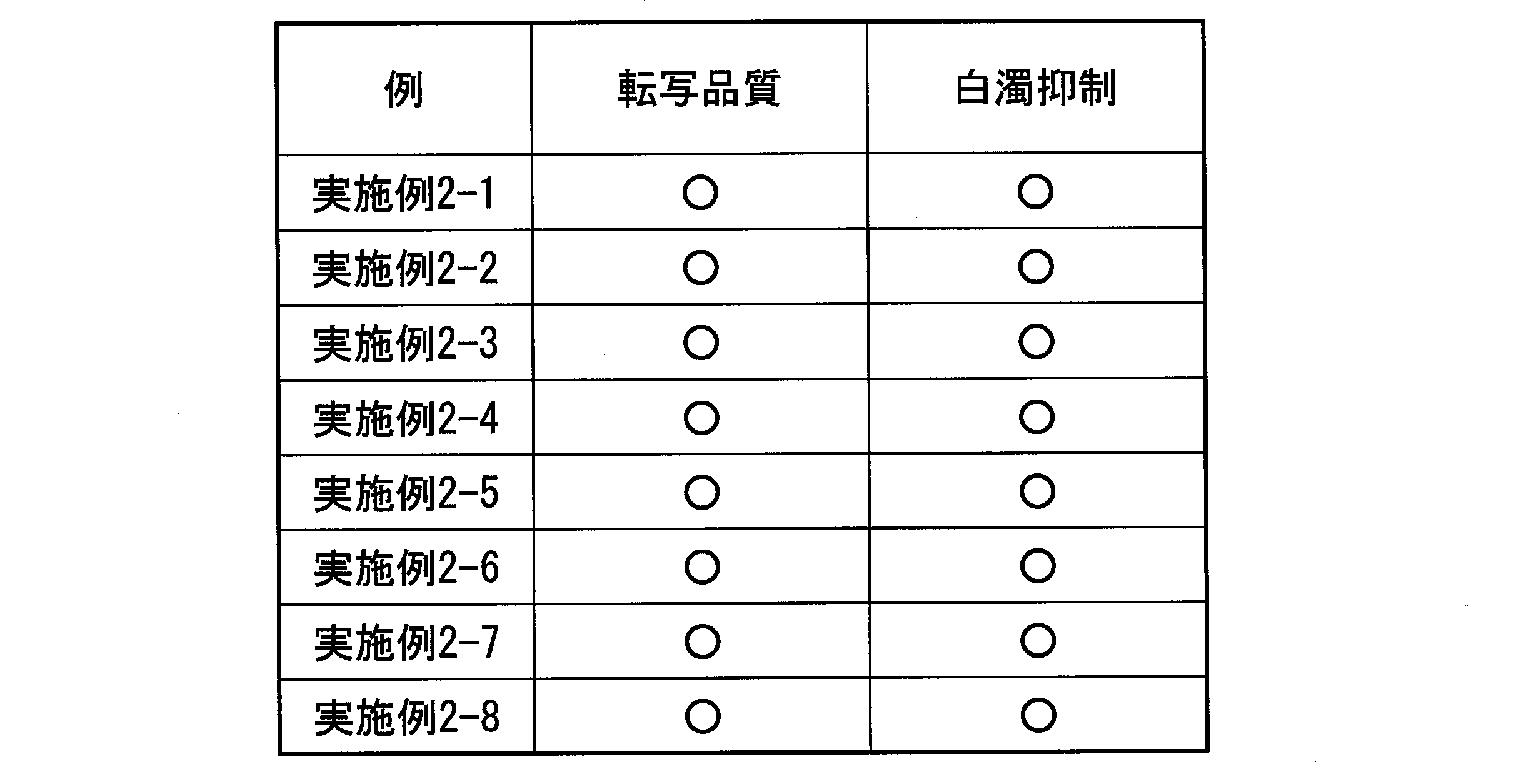
また、フラットホットスタンピングでは、転写領域に熱圧が集中するため、転写領域に掛かる圧力が大きくなりがちであり、白濁が生じやすい。
沈み込み制御層の変形制限剤が、軟化温度が90℃以上130℃以下の高ガラス転移温度重合体である場合、ホットスタンピング時に転写領域の内側では高ガラス転移温度重合体が軟化し、高弾性になるのに対し、転写領域の外側では、高ガラス転移温度重合体は軟化しないため弾性は低いままとなる。そのため、ホットスタンピングの最終工程でキャリアを剥離し、転写領域内の積層光学構造体のみ転写する際に、沈み込み制御層の転写領域の境界の高ガラス転移温度重合体に応力が集中することで、沈み込み制御層の転写領域の境界が確実に破断し、転写時のバリが抑えられたと考えられる。
沈み込み制御層形成用インキAおよび接着層形成用インキAに代えて、下記沈み込み制御層形成用インキCAおよび接着層形成用インキCAを用いた点を除き、実施例1と同様の方法で実施例3-1のホットスタンピング箔を作製した。
(沈み込み制御層形成用インキCA)
結晶性ポリエステル(軟質樹脂(融点100℃)、ディスパージョン溶液)
62.4部
シリカフィラー(富士シリシア化学社製 サイロホービック100)
3.8部
メチルエチルケトン 33.8部
(接着層形成用インキCA)
アクリル樹脂(樹脂成分) 49.2部
ポリエステル樹脂(樹脂成分) 1.3部
消泡剤 0.3部
シリカ(スペーサー粒子、平均粒径8.0μm レーザー法による測定)
1.4部
シリカ(スペーサー粒子、平均粒径14.0μm レーザー法による測定)
0.9部
ナノシリカ(無機粉体フィラー、平均粒径10~15nm レーザー法による測定) 32.3部
メチルエチルケトン 12.6部
トルエン 2.0部
沈み込み制御層形成用インキCAに代えて、下記沈み込み制御層形成用インキCBを用いた点を除き、実施例3-1と同様の方法で実施例3-2のホットスタンピング箔を作製した。
(沈み込み制御層形成用インキCB)
結晶性ポリエステル(軟質樹脂(融点100℃)、ディスパージョン溶液)
66.7部
塩化ビニル酢酸ビニル共重合体 2.7部
シリカフィラー(富士シリシア化学社製 サイロホービック100)
2.0部
メチルエチルケトン 28.6部
沈み込み制御層形成用インキCAに代えて、下記沈み込み制御層形成用インキCCを用いた点を除き、実施例3-1と同様の方法で実施例3-3のホットスタンピング箔を作製した。
(沈み込み制御層形成用インキCC)
結晶性ポリエステル(軟質樹脂(融点100℃)、ディスパージョン溶液)
76.9部
シリカフィラー(富士シリシア化学社製 サイロホービック100)
2.3部
メチルエチルケトン 20.8部
沈み込み制御層形成用インキCAに代えて、下記沈み込み制御層形成用インキCDを用いた点を除き、実施例3-1と同様の方法で実施例3-4のホットスタンピング箔を作製した。
(沈み込み制御層形成用インキCD)
結晶性ポリエステル(軟質樹脂(融点100℃)、ディスパージョン溶液)
62.4部
シリカフィラー(富士シリシア化学社製 サイロホービック100)
3.8部
メチルエチルケトン 33.8部
沈み込み制御層形成用インキCAに代えて、下記沈み込み制御層形成用インキCEを用いた点を除き、実施例3-1と同様の方法で実施例3-5のホットスタンピング箔を作製した。
(沈み込み制御層形成用インキCE)
結晶性ポリエステル(軟質樹脂(融点107℃)、ディスパージョン溶液)
60.4部
シリカフィラー(富士シリシア化学社製 サイロホービック100)
5.8部
メチルエチルケトン 33.8部
沈み込み制御層形成用インキCAに代えて、下記沈み込み制御層形成用インキCFを用いた点を除き、実施例3-1と同様の方法で実施例3-6のホットスタンピング箔を作製した。
(沈み込み制御層形成用インキCF)
結晶性ポリエステル(軟質樹脂(融点111℃)、ディスパージョン溶液)
62.4部
シリカフィラー(富士シリシア化学社製 サイロホービック100)
3.8部
メチルエチルケトン 33.8部
接着層形成用インキCAに代えて、下記接着層形成用インキCBを用いた点を除き、実施例3-1と同様の方法で実施例3-7のホットスタンピング箔を作製した。
(接着層形成用インキCB)
アクリル樹脂(樹脂成分) 49.2部
ポリエステル樹脂(樹脂成分) 1.3部
消泡剤 0.3部
シリカ(破断促進粒子、平均粒径3.4~5.5μm、アスペクト比30~50、レーザー法による測定) 1.4部
シリカ(スペーサー粒子、平均粒径14.0μm レーザー法による測定)
0.9部
ナノシリカ(無機粉体フィラー、平均粒径10~15nm レーザー法による測定) 32.3部
メチルエチルケトン 12.6部
トルエン 2.0部
接着層形成用インキCAに代えて、下記接着層形成用インキCCを用いた点を除き、実施例3-1と同様の方法で実施例3-8のホットスタンピング箔を作製した。
(接着層形成用インキCC)
アクリル樹脂(樹脂成分) 49.2部
ポリエステル樹脂(樹脂成分) 1.3部
消泡剤 0.3部
シリカ(破断促進粒子、平均粒径2.7μm、レーザー法による測定)
1.4部
シリカ(スペーサー粒子、平均粒径14.0μm レーザー法による測定)
0.9部
ナノシリカ(無機粉体フィラー、平均粒径10~15nm レーザー法による測定) 32.3部
メチルエチルケトン 12.6部
トルエン 2.0部
接着層形成用インキCAに代えて、下記接着層形成用インキCDを用いた点を除き、実施例3-1と同様の方法で実施例3-9のホットスタンピング箔を作製した。
(接着層形成用インキBD)
アクリル樹脂(樹脂成分) 49.2部
ポリエステル樹脂(樹脂成分) 1.3部
消泡剤 0.3部
シリカ(スペーサー粒子、平均粒径5.3μm、レーザー法による測定)
1.4部
シリカ(スペーサー粒子、平均粒径8.84μm レーザー法による測定)
0.9部
ナノシリカ(無機粉体フィラー、平均粒径10~15nm レーザー法による測定) 32.3部
メチルエチルケトン 12.6部
トルエン 2.0部
接着層形成用インキCAに代えて、下記接着層形成用インキCEを用いた点を除き、実施例3-1と同様の方法で実施例3-10のホットスタンピング箔を作製した。
(接着層形成用インキCE)
アクリル樹脂(樹脂成分) 49.2部
ポリエステル樹脂(樹脂成分) 1.3部
消泡剤 0.3部
シリカ(スペーサー粒子、平均粒径6.6μm、レーザー法による測定)
1.4部
シリカ(スペーサー粒子、平均粒径8.0μm レーザー法による測定)
0.9部
ナノシリカ(無機粉体フィラー、平均粒径10~15nm レーザー法による測定) 32.3部
メチルエチルケトン 12.6部
トルエン 2.0部
接着層形成用インキCAに代えて、下記接着層形成用インキCFを用いた点を除き、実施例3-1と同様の方法で比較例3-1のホットスタンピング箔を作製した。
(接着層形成用インキCF)
アクリル樹脂(樹脂成分) 51.5部
ポリエステル樹脂(樹脂成分) 1.3部
消泡剤 0.3部
ナノシリカ(無機粉体フィラー、平均粒径10~15nm レーザー法による測定) 32.3部
メチルエチルケトン 12.6部
トルエン 2.0部
(低温低圧転写の密着性評価)
厚み約200μmの上質紙を転写対象とし、各例のホットスタンピング箔を版面温度100℃、圧力0.4t/cm2、加圧時間0.3秒の条件にて転写した。転写箇所にセロハンテープ(ニチバンLP-24)を貼り付け圧着した後、1cm/2.5秒の速度にて、転写面に対し垂直方向に剥離した。剥離後のセロハンテープを黒PETフィルム(東レ ルミラー 188×30)に貼り付け、目視にて密着評価した。剥離した点状の積層光学構造体が、密集して付着している場合は、×(密着性に問題あり)、散在している場合または存在しない場合は、○(密着性に問題なし)とした。この基準は、散在した剥離では転写された絵柄の見た目に与える影響は小さいが、密集して剥離すると転写された絵柄の見た目に与える影響が大きいことに基づく。

ストライプ箔は、積層光学構造体の長辺が100mm以上と長く形成されたり、複数の積層光学構造体を幅方向に並べた状態で転写されたりすることが多く、転写面積が大きくなりやすい。その結果、転写時の熱圧がかかりにくく、低温低圧条件でも十分な密着性を確保して転写されることが重要になる。
転写対象に対する密着性を高める簡便な方法としては、接着層のタック性を高める方法や、接着層の融点を下げる方法等が考えられるが、これらの方法を採用すると、ブロッキングが生じやすくなるため、ブロッキング抑制との両立は非常に困難である。
第三グループの実施例では、いずれも沈み込み制御層が融点を有する結晶性樹脂を含有している。したがって、転写時の温度条件を考慮して適切な融点を有する樹脂を選択することにより、低温低圧転写においても沈み込み制御層を溶融させることができる。その結果、転写時に沈み込み制御層が溶融し、転写時の熱が接着層に伝わりやすくなり、高い密着性を実現することができる。
また、保管時に溶融しないような融点を有する樹脂を選択することで、上述したように接着層のスペーサー粒子の沈み込みを適正に制御することができるため、ブロッキングの抑制効果も同時に得ることができる。
接着層に粒子径の異なる3種類の粒子を含む実施例3-1、および3-7から3-10も、良好なブロッキング抑制を示した。これは、粒径の大きな粒子が粒径の小さな粒子にかかる圧力を低減し、沈み込み制御層にやわらかい樹脂を適用しても、保管中に粒径の小さな粒子が沈み込みすぎないことによると考えられる。径の大きな粒子には、圧力が集中しやすいが、粒子の数を少なくすることで、目視できる程度の白化の発生を抑えることができる。
以上より、第三グループの実施例の構成は、ストライプ箔の構成に特に好適であることが示された。
10 キャリア
20 積層光学構造体
25 積層光学装飾体
30 沈み込み制御層
40、60 接着層
41 スペーサー粒子
42 粉体フィラー
45 樹脂成分
100 積層光学装飾体付印刷体
101 紙幣(印刷体)
Claims (24)
- 転写熱圧を加えることにより転写対象に転写されるホットスタンピング箔であって、
ベースフィルムまたはコートされたベースフィルムのキャリアと、
前記キャリア上に形成された積層光学構造体を含む積層光学装飾体と、
軟質樹脂と変形制限剤とを含有し、前記積層光学構造体上に形成された沈み込み制御層と、
前記沈み込み制御層上に形成された接着層と、
を備え、
前記接着層は、
常温より低いガラス転移温度の熱可塑樹脂を含有し、前記接着層の厚みを規定する樹脂成分と、
前記接着層の厚みよりも大きい粒径を有し、一部が前記樹脂成分から突出するスペーサー粒子と、を含有し、
前記スペーサー粒子が、転写熱圧後に前記沈み込み制御層に沈み込む、ホットスタンピング箔。 - 前記変形制限剤は、前記接着層の厚みよりも小さい粒径の無機粉体フィラーおよび高ガラス転移温度重合体の少なくとも一方を含む、
請求項1に記載のホットスタンピング箔。 - 前記スペーサー粒子の平均粒径は、前記接着層の厚さと前記沈み込み制御層の厚さの和である総厚より大きく、前記総厚の2倍以下である、
請求項1または2に記載のホットスタンピング箔。 - 前記転写熱圧後における前記スペーサー粒子の沈み込み量が、過負荷熱圧時における前記スペーサー粒子の沈み込み量の20%以上60%以下である、
請求項1から3のいずれか一項に記載のホットスタンピング箔。 - 前記変形制限剤が塩化ビニル酢酸ビニル共重合体である、
請求項1に記載のホットスタンピング箔。 - 前記軟質樹脂が酸変性ポリオレフィン樹脂である、
請求項1から5のいずれか一項に記載のホットスタンピング箔。 - 前記酸変性ポリオレフィン樹脂は、ポリエチレンと(メタ)アクリル酸の共重合樹脂である、
請求項6に記載のホットスタンピング箔。 - 前記軟質樹脂は、アクリル樹脂である、
請求項1から7のいずれか一項に記載のホットスタンピング箔。 - 前記沈み込み制御層は、シラノール結合を含有する、
請求項1から8のいずれか一項に記載のホットスタンピング箔。 - 前記沈み込み制御層は、ウレタン結合を含有する、
請求項1から8のいずれか一項に記載のホットスタンピング箔。 - 前記変形制限剤は高ガラス転移温度重合体を含み、
前記高ガラス転移温度重合体と前記軟質樹脂は2相状態に相分離しており、
前記高ガラス転移温度重合体は連続相であり、前記高ガラス転移温度重合体のガラス転移温度は、前記軟質樹脂のガラス転移温度以上である、
請求項1に記載のホットスタンピング箔。 - 前記接着層は、前記接着層の厚みよりも小さい粒径の粉体フィラーを含有する、
請求項1から11のいずれか一項に記載のホットスタンピング箔。 - 転写熱圧を加えることにより転写対象に転写されるホットスタンピング箔であって、
ベースフィルムまたはコートされたベースフィルムのキャリアと、
前記キャリア上に形成された積層光学構造体を含む積層光学装飾体と、
前記積層光学構造体上に形成された沈み込み制御層と、
前記沈み込み制御層上に形成された接着層と、
を備え、
前記接着層は、
前記接着層の厚みを規定する樹脂成分と、
前記接着層の厚みよりも大きい粒径を有し、一部が前記樹脂成分から突出するスペーサー粒子と、を含有し、
前記転写熱圧後における前記スペーサー粒子の沈み込み量が、過負荷熱圧時における前記スペーサー粒子の沈み込み量の20%以上60%以下である、
ホットスタンピング箔。 - 前記接着層は、前記接着層の厚みよりも小さい粒径の粉体フィラーを含有する、
請求項13に記載のホットスタンピング箔。 - 前記沈み込み制御層は、塩化ビニル酢酸ビニル共重合樹脂を含有する、
請求項13または14に記載のホットスタンピング箔。 - 前記沈み込み制御層は、酸変性ポリオレフィン樹脂をさらに含有する、
請求項15に記載のホットスタンピング箔。 - 前記沈み込み制御層は、ポリエチレンと(メタ)アクリル酸の共重合樹脂をさらに含有する、
請求項15に記載のホットスタンピング箔。 - 前記沈み込み制御層は、シラノール結合を含有する、
請求項13から17のいずれか一項に記載のホットスタンピング箔。 - 前記沈み込み制御層は、ウレタン結合を含有する、
請求項13から18のいずれか一項に記載のホットスタンピング箔。 - 前記沈み込み制御層は、融点を持つ樹脂で形成されている、
請求項13に記載のホットスタンピング箔。 - 前記融点が120℃以下である、請求項20に記載のホットスタンピング箔。
- 前記沈み込み制御層がフィラーを含有する、請求項20に記載のホットスタンピング箔。
- 前記接着層がアクリル粘着剤を含有する、請求項20に記載のホットスタンピング箔。
- 請求項1から23のいずれか一項に記載のホットスタンピング箔を用い印刷体に前記積層光学装飾体が熱転写された積層光学装飾体付印刷体。
Priority Applications (5)
| Application Number | Priority Date | Filing Date | Title |
|---|---|---|---|
| KR1020197029855A KR102485172B1 (ko) | 2017-04-21 | 2018-04-20 | 핫 스탬핑박 및 적층 광학 장식체 구비 인쇄체 |
| AU2018254149A AU2018254149B2 (en) | 2017-04-21 | 2018-04-20 | Hot-stamping foil and printing body equipped with laminated optical decoration body |
| EP23175665.1A EP4230428B1 (en) | 2017-04-21 | 2018-04-20 | Hot-stamping foil |
| EP18787252.8A EP3613593B1 (en) | 2017-04-21 | 2018-04-20 | Hot-stamping foil and printing body equipped with laminated optical decoration body |
| US16/653,411 US11077693B2 (en) | 2017-04-21 | 2019-10-15 | Hot-stamping foil and print equipped with laminated optical decoration |
Applications Claiming Priority (2)
| Application Number | Priority Date | Filing Date | Title |
|---|---|---|---|
| JP2017-084548 | 2017-04-21 | ||
| JP2017084548 | 2017-04-21 |
Related Child Applications (1)
| Application Number | Title | Priority Date | Filing Date |
|---|---|---|---|
| US16/653,411 Continuation US11077693B2 (en) | 2017-04-21 | 2019-10-15 | Hot-stamping foil and print equipped with laminated optical decoration |
Publications (1)
| Publication Number | Publication Date |
|---|---|
| WO2018194178A1 true WO2018194178A1 (ja) | 2018-10-25 |
Family
ID=63855814
Family Applications (1)
| Application Number | Title | Priority Date | Filing Date |
|---|---|---|---|
| PCT/JP2018/016372 Ceased WO2018194178A1 (ja) | 2017-04-21 | 2018-04-20 | ホットスタンピング箔および積層光学装飾体付印刷体 |
Country Status (6)
| Country | Link |
|---|---|
| US (1) | US11077693B2 (ja) |
| EP (2) | EP4230428B1 (ja) |
| JP (2) | JP6922824B2 (ja) |
| KR (1) | KR102485172B1 (ja) |
| AU (1) | AU2018254149B2 (ja) |
| WO (1) | WO2018194178A1 (ja) |
Cited By (6)
| Publication number | Priority date | Publication date | Assignee | Title |
|---|---|---|---|---|
| CN112026420A (zh) * | 2020-09-09 | 2020-12-04 | 浙江驰怀烫印科技股份有限公司 | 一种高亮烫金箔 |
| WO2021039785A1 (ja) * | 2019-08-29 | 2021-03-04 | 凸版印刷株式会社 | ホットスタンピング箔および光学可変デバイス付印刷体 |
| JPWO2021256482A1 (ja) * | 2020-06-16 | 2021-12-23 | ||
| EP3922478A4 (en) * | 2019-03-29 | 2022-11-30 | Dai Nippon Printing Co., Ltd. | Intermediate transfer medium, recording medium, decorative sheet, and decorative product |
| JP2022178048A (ja) * | 2021-05-19 | 2022-12-02 | 凸版印刷株式会社 | ホットスタンピング箔 |
| KR20240059615A (ko) | 2021-08-30 | 2024-05-07 | 도판 홀딩스 가부시키가이샤 | 전사박, 전사물, 표시체, 표시체의 진정의 검증 방법 및 검증 장치, 그리고 개체 인증 방법 |
Families Citing this family (7)
| Publication number | Priority date | Publication date | Assignee | Title |
|---|---|---|---|---|
| JP6922824B2 (ja) * | 2017-04-21 | 2021-08-18 | 凸版印刷株式会社 | 転写箔およびovd部付印刷体 |
| US20220138305A1 (en) * | 2019-02-05 | 2022-05-05 | Tokyo Ohka Kogyo Co., Ltd. | Authentication object, authentication system, and authentication medium production method |
| JP6973537B2 (ja) * | 2020-03-16 | 2021-12-01 | 凸版印刷株式会社 | 転写箔 |
| EP4210965A2 (en) * | 2020-09-11 | 2023-07-19 | De La Rue International Limited | Security devices and methods of manufacture thereof |
| JP7010353B2 (ja) * | 2020-10-21 | 2022-01-26 | 凸版印刷株式会社 | 転写箔及びその製造方法 |
| CN113561465B (zh) * | 2021-07-28 | 2023-04-28 | 东莞市聚龙高科电子技术有限公司 | 一种塑胶产品表面3d纹理的形成方法及塑胶产品 |
| WO2023106247A1 (ja) * | 2021-12-06 | 2023-06-15 | タツタ電線株式会社 | 転写フィルム及び転写フィルム付き電磁波シールドフィルム |
Citations (9)
| Publication number | Priority date | Publication date | Assignee | Title |
|---|---|---|---|---|
| JPH08192566A (ja) * | 1995-01-19 | 1996-07-30 | Dainippon Printing Co Ltd | 転写シート |
| JP2001071698A (ja) | 1999-09-02 | 2001-03-21 | Toppan Printing Co Ltd | Ovd形成媒体の偽造防止方法及び偽造防止を施したovd転写箔及びovd形成媒体 |
| JP2003246194A (ja) * | 2002-02-27 | 2003-09-02 | Toppan Printing Co Ltd | 転写シート |
| JP2005070064A (ja) * | 2002-07-26 | 2005-03-17 | Dainippon Printing Co Ltd | 体積ホログラム転写箔 |
| JP2008006709A (ja) * | 2006-06-29 | 2008-01-17 | Dainippon Printing Co Ltd | 転写箔 |
| JP2009003197A (ja) * | 2007-06-21 | 2009-01-08 | Dainippon Printing Co Ltd | 体積ホログラム転写箔および体積ホログラム積層体 |
| JP2009291996A (ja) | 2008-06-04 | 2009-12-17 | Nissha Printing Co Ltd | 転写シート、転写シートの製造方法、転写成形品の製造方法および転写成形品 |
| JP2010240994A (ja) * | 2009-04-07 | 2010-10-28 | Dainippon Printing Co Ltd | ホログラム転写箔 |
| JP2017084548A (ja) | 2015-10-27 | 2017-05-18 | 日東電工株式会社 | 導電性フィルム |
Family Cites Families (7)
| Publication number | Priority date | Publication date | Assignee | Title |
|---|---|---|---|---|
| DE19531313A1 (de) * | 1995-08-25 | 1997-02-27 | Basf Magnetics Gmbh | Heißsiegelfolie |
| US6912089B2 (en) * | 2000-12-06 | 2005-06-28 | Fuji Photo Film Co., Ltd. | Optical diffusion film and process of producing optical diffusion film |
| US7491472B2 (en) * | 2002-07-26 | 2009-02-17 | Dai Nippon Printing Co., Ltd. | Volume hologram transfer foil |
| US20040023019A1 (en) * | 2002-08-02 | 2004-02-05 | 3M Innovative Properties Company | Particulate transfer film with improved bead carrier |
| US8559084B2 (en) * | 2007-06-19 | 2013-10-15 | Dai Nippon Printing Co., Ltd. | Volume hologram transfer foil, volume hologram laminate, and production method thereof |
| KR102190374B1 (ko) * | 2012-08-21 | 2020-12-11 | 쓰리엠 이노베이티브 프로퍼티즈 컴파니 | 바인더-결핍 슬립 코팅을 갖는 물품과 그 물품을 제조하기 위한 방법 |
| JP6922824B2 (ja) * | 2017-04-21 | 2021-08-18 | 凸版印刷株式会社 | 転写箔およびovd部付印刷体 |
-
2018
- 2018-04-20 JP JP2018081885A patent/JP6922824B2/ja active Active
- 2018-04-20 EP EP23175665.1A patent/EP4230428B1/en active Active
- 2018-04-20 JP JP2018081884A patent/JP6922823B2/ja active Active
- 2018-04-20 KR KR1020197029855A patent/KR102485172B1/ko active Active
- 2018-04-20 EP EP18787252.8A patent/EP3613593B1/en active Active
- 2018-04-20 WO PCT/JP2018/016372 patent/WO2018194178A1/ja not_active Ceased
- 2018-04-20 AU AU2018254149A patent/AU2018254149B2/en active Active
-
2019
- 2019-10-15 US US16/653,411 patent/US11077693B2/en active Active
Patent Citations (9)
| Publication number | Priority date | Publication date | Assignee | Title |
|---|---|---|---|---|
| JPH08192566A (ja) * | 1995-01-19 | 1996-07-30 | Dainippon Printing Co Ltd | 転写シート |
| JP2001071698A (ja) | 1999-09-02 | 2001-03-21 | Toppan Printing Co Ltd | Ovd形成媒体の偽造防止方法及び偽造防止を施したovd転写箔及びovd形成媒体 |
| JP2003246194A (ja) * | 2002-02-27 | 2003-09-02 | Toppan Printing Co Ltd | 転写シート |
| JP2005070064A (ja) * | 2002-07-26 | 2005-03-17 | Dainippon Printing Co Ltd | 体積ホログラム転写箔 |
| JP2008006709A (ja) * | 2006-06-29 | 2008-01-17 | Dainippon Printing Co Ltd | 転写箔 |
| JP2009003197A (ja) * | 2007-06-21 | 2009-01-08 | Dainippon Printing Co Ltd | 体積ホログラム転写箔および体積ホログラム積層体 |
| JP2009291996A (ja) | 2008-06-04 | 2009-12-17 | Nissha Printing Co Ltd | 転写シート、転写シートの製造方法、転写成形品の製造方法および転写成形品 |
| JP2010240994A (ja) * | 2009-04-07 | 2010-10-28 | Dainippon Printing Co Ltd | ホログラム転写箔 |
| JP2017084548A (ja) | 2015-10-27 | 2017-05-18 | 日東電工株式会社 | 導電性フィルム |
Cited By (11)
| Publication number | Priority date | Publication date | Assignee | Title |
|---|---|---|---|---|
| EP3922478A4 (en) * | 2019-03-29 | 2022-11-30 | Dai Nippon Printing Co., Ltd. | Intermediate transfer medium, recording medium, decorative sheet, and decorative product |
| WO2021039785A1 (ja) * | 2019-08-29 | 2021-03-04 | 凸版印刷株式会社 | ホットスタンピング箔および光学可変デバイス付印刷体 |
| JPWO2021039785A1 (ja) * | 2019-08-29 | 2021-03-04 | ||
| EP4024095A4 (en) * | 2019-08-29 | 2023-10-04 | Toppan Inc. | HOT STAMPING FOIL AND PRINTED ITEM WITH OPTICALLY VARIABLE DEVICE |
| JP7476902B2 (ja) | 2019-08-29 | 2024-05-01 | Toppanホールディングス株式会社 | ホットスタンピング箔および光学可変デバイス付印刷体 |
| JPWO2021256482A1 (ja) * | 2020-06-16 | 2021-12-23 | ||
| WO2021256482A1 (ja) * | 2020-06-16 | 2021-12-23 | 凸版印刷株式会社 | ホットスタンピング箔 |
| JP7283637B2 (ja) | 2020-06-16 | 2023-05-30 | 凸版印刷株式会社 | ホットスタンピング箔 |
| CN112026420A (zh) * | 2020-09-09 | 2020-12-04 | 浙江驰怀烫印科技股份有限公司 | 一种高亮烫金箔 |
| JP2022178048A (ja) * | 2021-05-19 | 2022-12-02 | 凸版印刷株式会社 | ホットスタンピング箔 |
| KR20240059615A (ko) | 2021-08-30 | 2024-05-07 | 도판 홀딩스 가부시키가이샤 | 전사박, 전사물, 표시체, 표시체의 진정의 검증 방법 및 검증 장치, 그리고 개체 인증 방법 |
Also Published As
| Publication number | Publication date |
|---|---|
| KR102485172B1 (ko) | 2023-01-06 |
| JP6922824B2 (ja) | 2021-08-18 |
| JP2018183992A (ja) | 2018-11-22 |
| EP3613593B1 (en) | 2023-07-19 |
| KR20190139867A (ko) | 2019-12-18 |
| EP4230428A2 (en) | 2023-08-23 |
| EP3613593A4 (en) | 2021-01-20 |
| JP2018183991A (ja) | 2018-11-22 |
| EP3613593A1 (en) | 2020-02-26 |
| US20200039273A1 (en) | 2020-02-06 |
| AU2018254149B2 (en) | 2022-09-01 |
| US11077693B2 (en) | 2021-08-03 |
| AU2018254149A1 (en) | 2019-12-05 |
| JP6922823B2 (ja) | 2021-08-18 |
| EP4230428B1 (en) | 2025-01-29 |
| EP4230428A3 (en) | 2023-12-13 |
Similar Documents
| Publication | Publication Date | Title |
|---|---|---|
| KR102485172B1 (ko) | 핫 스탬핑박 및 적층 광학 장식체 구비 인쇄체 | |
| JP7331997B2 (ja) | ホットスタンピング箔および積層光学装飾体付印刷体 | |
| JP5477046B2 (ja) | 表示体及びその製造方法 | |
| JP7476902B2 (ja) | ホットスタンピング箔および光学可変デバイス付印刷体 | |
| JP7283637B2 (ja) | ホットスタンピング箔 | |
| JPWO2008133113A1 (ja) | 真偽判定方法及び識別器及び偏光板 | |
| JP4967566B2 (ja) | 転写シート | |
| JP6973537B2 (ja) | 転写箔 | |
| JP2022178048A (ja) | ホットスタンピング箔 | |
| JP2024027328A (ja) | ホットスタンピング箔 | |
| JP5585132B2 (ja) | 表示体、粘着ステッカ、転写箔及び表示体付き物品 | |
| JP4967567B2 (ja) | 転写シート | |
| JP2024013894A (ja) | 転写箔 | |
| JP2007003759A (ja) | 偽造防止媒体及び偽造防止シール | |
| JP4867526B2 (ja) | 偽造防止磁気テープ転写シートおよびカード |
Legal Events
| Date | Code | Title | Description |
|---|---|---|---|
| 121 | Ep: the epo has been informed by wipo that ep was designated in this application |
Ref document number: 18787252 Country of ref document: EP Kind code of ref document: A1 |
|
| ENP | Entry into the national phase |
Ref document number: 20197029855 Country of ref document: KR Kind code of ref document: A |
|
| NENP | Non-entry into the national phase |
Ref country code: DE |
|
| WWE | Wipo information: entry into national phase |
Ref document number: 2018787252 Country of ref document: EP |
|
| ENP | Entry into the national phase |
Ref document number: 2018787252 Country of ref document: EP Effective date: 20191121 |
|
| ENP | Entry into the national phase |
Ref document number: 2018254149 Country of ref document: AU Date of ref document: 20180420 Kind code of ref document: A |