WO2018193640A1 - ダンパ - Google Patents
ダンパ Download PDFInfo
- Publication number
- WO2018193640A1 WO2018193640A1 PCT/JP2017/025673 JP2017025673W WO2018193640A1 WO 2018193640 A1 WO2018193640 A1 WO 2018193640A1 JP 2017025673 W JP2017025673 W JP 2017025673W WO 2018193640 A1 WO2018193640 A1 WO 2018193640A1
- Authority
- WO
- WIPO (PCT)
- Prior art keywords
- cylinder
- magnetic field
- damper
- rod
- magnitude
- Prior art date
- Legal status (The legal status is an assumption and is not a legal conclusion. Google has not performed a legal analysis and makes no representation as to the accuracy of the status listed.)
- Ceased
Links
Images






Classifications
-
- F—MECHANICAL ENGINEERING; LIGHTING; HEATING; WEAPONS; BLASTING
- F16—ENGINEERING ELEMENTS AND UNITS; GENERAL MEASURES FOR PRODUCING AND MAINTAINING EFFECTIVE FUNCTIONING OF MACHINES OR INSTALLATIONS; THERMAL INSULATION IN GENERAL
- F16F—SPRINGS; SHOCK-ABSORBERS; MEANS FOR DAMPING VIBRATION
- F16F15/00—Suppression of vibrations in systems; Means or arrangements for avoiding or reducing out-of-balance forces, e.g. due to motion
- F16F15/02—Suppression of vibrations of non-rotating, e.g. reciprocating systems; Suppression of vibrations of rotating systems by use of members not moving with the rotating systems
-
- F—MECHANICAL ENGINEERING; LIGHTING; HEATING; WEAPONS; BLASTING
- F16—ENGINEERING ELEMENTS AND UNITS; GENERAL MEASURES FOR PRODUCING AND MAINTAINING EFFECTIVE FUNCTIONING OF MACHINES OR INSTALLATIONS; THERMAL INSULATION IN GENERAL
- F16F—SPRINGS; SHOCK-ABSORBERS; MEANS FOR DAMPING VIBRATION
- F16F15/00—Suppression of vibrations in systems; Means or arrangements for avoiding or reducing out-of-balance forces, e.g. due to motion
- F16F15/02—Suppression of vibrations of non-rotating, e.g. reciprocating systems; Suppression of vibrations of rotating systems by use of members not moving with the rotating systems
- F16F15/03—Suppression of vibrations of non-rotating, e.g. reciprocating systems; Suppression of vibrations of rotating systems by use of members not moving with the rotating systems using magnetic or electromagnetic means
-
- F—MECHANICAL ENGINEERING; LIGHTING; HEATING; WEAPONS; BLASTING
- F16—ENGINEERING ELEMENTS AND UNITS; GENERAL MEASURES FOR PRODUCING AND MAINTAINING EFFECTIVE FUNCTIONING OF MACHINES OR INSTALLATIONS; THERMAL INSULATION IN GENERAL
- F16F—SPRINGS; SHOCK-ABSORBERS; MEANS FOR DAMPING VIBRATION
- F16F15/00—Suppression of vibrations in systems; Means or arrangements for avoiding or reducing out-of-balance forces, e.g. due to motion
- F16F15/02—Suppression of vibrations of non-rotating, e.g. reciprocating systems; Suppression of vibrations of rotating systems by use of members not moving with the rotating systems
- F16F15/04—Suppression of vibrations of non-rotating, e.g. reciprocating systems; Suppression of vibrations of rotating systems by use of members not moving with the rotating systems using elastic means
Definitions
- the present invention relates to a damper.
- Patent Document 1 discloses a conventional damper.
- a steel ball as a granular material is filled in a space surrounded by a cylinder and a pair of caps, and the piston moves along with the movement of the rod (rod). It is structured to be displaced relative to the cylinder in the inside filled with.
- the pair of caps is always urged by a pair of springs so as to decrease the volume of the space in which the granular material is stored.
- An electromagnet is provided on the outer periphery of the cylinder.
- this damper the flow of the granular material is promoted, and the piston moves away from the granular material to generate a damping force. Furthermore, when an electric current is passed through the electromagnet of this damper, the binding force of the granular material in the direction along the direction of the line of magnetic force of the electromagnet increases. As a result, the frictional force between the granular materials increases, and the damping force of the damper increases accordingly. Thereby, this damper can change the characteristic of the generated damping force by controlling the magnitude of the current flowing through the electromagnet.
- the present invention has been made in view of the above-described conventional situation, and solves the problem of providing a damper capable of generating a damping force satisfactorily and easily adjusting the magnitude of the generated damping force. It should be a challenge.
- the damper of the present invention includes a case, a rod, particles, and a magnetic field generation unit. From the case, a rod that reciprocally moves in the axial direction or rotatable around the axis protrudes to the outside.
- the particles have the properties and elasticity of permanent magnets, and a plurality of particles are filled in the case.
- the magnetic field generation unit generates a predetermined magnetic field in the case.
- the magnetic field generator of the damper of the present invention can change the strength of the magnetic field generated in the case.
- the damper of the present invention may be provided with a piston that is disposed in the case, is connected to a rod that can reciprocate in the axial direction, and reciprocates in the case together with the rod.
- the damper of the present invention may be provided in a case, and may be provided with a rotor that is connected to a rod that is rotatable around an axis and that rotates in the case together with the rod.
- the piston can have the characteristics of a permanent magnet.
- the rotor can have the characteristics of a permanent magnet.
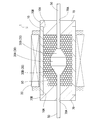
- FIG. 3 is a cross-sectional view showing the damper according to the first embodiment.
- 3 is a schematic diagram of a granular material filled in a case of a damper according to Embodiment 1.
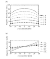
- FIG. FIG. 6 is a graph showing the magnitude of magnetic flux density in the vicinity of the center axis of a cylinder when the magnitude of the current flowing through the magnetic field generation unit of the damper according to the first embodiment is changed for each predetermined magnitude; A) shows the magnitude of the magnetic flux density in the direction of the central axis of the cylinder, and (B) shows the magnitude of the magnetic flux density in the direction (radial direction) perpendicular to the central axis of the cylinder.
- the magnitude of the speed (hereinafter referred to as frequency) for reciprocating the rod in the direction of the central axis of the cylinder is changed for each predetermined magnitude, the magnitude of the speed (hereinafter referred to as frequency) for reciprocating the rod in the direction of the central axis of the cylinder is It is a graph which shows the relationship between the displacement amount with respect to the cylinder of a rod when it changes for every predetermined magnitude
- size of the electric current sent through is 6A is shown.
- the magnitude of the current flowing through the magnetic field generator of the damper according to the first embodiment is 0, 3, 6A, the attenuation energy for each when the magnitude of the frequency is changed between 1 to 5 Hz every 1 Hz.
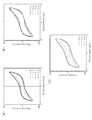
- size of. 6 is a graph showing the relationship between the amount of displacement of the rod with respect to the cylinder and the damping force when the magnitude of the current flowing through the magnetic field generation unit of the damper according to the first embodiment is changed for each predetermined magnitude when the frequency is 1 Hz.
- (A) shows the case where the magnitude of the current passed through the magnetic field generator is 0, 1, 2, 3A
- (B) shows the magnitude of the current passed through the magnetic field generator is 3, 4, 5, 6A
- (C) shows the case where the magnitude of the current flowing through the magnetic field generation unit is 0, 3, 6A.
- 6 is a graph showing the relationship between the amount of displacement of the rod with respect to the cylinder and the damping force when the magnitude of the current flowing through the magnetic field generation unit of the damper according to the first embodiment is changed for each predetermined magnitude when the frequency is 3 Hz.
- (A) shows the case where the magnitude of the current passed through the magnetic field generator is 0, 1, 2, 3A
- (B) shows the magnitude of the current passed through the magnetic field generator is 3, 4, 5, 6A.
- (C) shows the case where the magnitude of the current flowing through the magnetic field generation unit is 0, 3, 6A.
- 5 is a graph showing the relationship between the amount of displacement of the rod with respect to the cylinder and the damping force when the magnitude of the current flowing through the magnetic field generation unit of the damper according to the first embodiment is changed for each predetermined magnitude when the frequency is 5 Hz.
- (A) shows the case where the magnitude of the current passed through the magnetic field generator is 0, 1, 2, 3A
- (B) shows the magnitude of the current passed through the magnetic field generator is 3, 4, 5, 6A.
- (C) shows the case where the magnitude of the current flowing through the magnetic field generation unit is 0, 3, 6A.
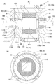
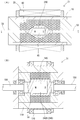
- FIG. 4 is a cross-sectional view showing a damper according to a second embodiment, where (A) is a cross-sectional view in the central axis direction of the rotor, and (B) is a cross-sectional view along AA in FIG. It is sectional drawing which shows the damper of Embodiment 3, 4, (A) shows a mode that the magnet was provided in the piston, and (B) shows a mode that the magnet was provided in the rotor.
- Embodiments 1 to 4 embodying the damper of the present invention will be described with reference to the drawings.
- the damper 1 As shown in FIG. 1, the damper 1 according to the first embodiment includes a cylinder 10 that is a case, a piston 30, a rod 50, a pair of rod guides 70, elastomer particles 90 that are a plurality of particles, and A magnetic field generation unit 20 is provided.
- the cylinder 10 has a cylindrical shape with both ends open.
- the piston 30 has a central portion 30A and both end portions 30B.
- the central portion 30A has a cylindrical shape.
- Both end portions 30B have a truncated cone shape whose outer diameter gradually decreases in a direction away from both end surfaces of the central portion 30A.
- a predetermined gap is formed between the outer peripheral surface of the piston 30 and the inner peripheral surface of the cylinder 10.
- the piston 30 is disposed in the cylinder 10.
- the rod 50 has a cylindrical shape.
- the rod 50 is continuous with the tip of both end portions 30 ⁇ / b> B of the piston 30 and extends in both directions of the piston 30.
- the rod 50 extends in the direction of the central axis of the cylinder 10 and protrudes from the open end portions 10 ⁇ / b> A at both ends of the cylinder 10 to the outside of the cylinder 10. That is, the piston 30 is connected to the rod 50.
- the rod guide 70 has a disk shape having a flange 70B on the outer periphery, and is connected to each open end 10A so as to close each open end 10A at both ends of the cylinder 10.
- These rod guides 70 are provided with through holes 70 ⁇ / b> A penetrating in the disc-like thickness direction at the disc-like center.
- the inner diameter of the through hole 70 ⁇ / b> A is slightly larger than the outer diameter of the rod 50.
- the through hole 70 ⁇ / b> A penetrates in the direction of the central axis of the cylinder 10 in a state where the rod guide 70 is fixed to the respective open end portions 10 ⁇ / b> A at both ends of the cylinder 10.
- the rod 50 is inserted into the through holes 70A of the rod guides 70 so as to be reciprocally movable. Both the rod 50 and the piston 30 can reciprocate within the cylinder 10 in the direction of the center axis of the cylinder 10.
- the cylinder 10, the piston 30, the rod 50, and the pair of rod guides 70 are nonmagnetic materials.
- the plurality of elastomer particles 90 has a spherical shape as shown in FIG.
- These elastomer particles 90 are elastic bodies made of silicone rubber having a durometer type A hardness (hereinafter referred to as hardness) of 60. Further, these elastomer particles 90 contain neodymium (Nd) particles 90A. The amount of neodymium (Nd) particles 90A contained in these elastomer particles 90 is about 60 wt. % (17.78 vol.%). Neodymium (Nd) particles 90A have magnetism. That is, the elastomer particle 90 has magnetism and elasticity. These elastomer particles 90 thus formed are magnetized and have a magnetic force.
- these elastomer particles 90 have the characteristics of permanent magnets. These elastomer particles 90 are filled in a space surrounded by the cylinder 10 and the pair of rod guides 70 (that is, in the cylinder 10) at a filling rate of 60%.
- the filling rate is expressed by the following equation (1).
- the filling volume is the volume of the space in which the elastomer particles 90 are filled.
- the magnetic field generating unit 20 is a metal wire whose surface is covered with an insulating film, which is wound around a plurality of times coaxially and bundled in a cylindrical shape having a predetermined width in the radial direction and an inner diameter slightly larger than the outer diameter of the cylinder 10. Is.
- the metal wire of the magnetic field generation unit 20 has a configuration in which both ends are drawn and current flows (not shown).
- the magnetic field generation unit 20 is arranged on the outer peripheral surface of the cylinder 10 by inserting the cylinder 10 so that the cylindrical inner side of the magnetic field generation unit 20 is along the outer peripheral surface of the cylinder 10.
- the elastomer particles 90 move through a predetermined gap between the outer peripheral surface of the piston 30 and the inner peripheral surface of the cylinder 10. To do. At this time, between the inner peripheral surface of the cylinder 10 and the elastomer particles 90 in contact with the inner peripheral surface of the cylinder 10, between the adjacent elastomer particles 90, and the outer peripheral surfaces of the rod 50 and the piston 30, and the rod 50 and the piston 30. A frictional force is generated between the elastic particles 90 and the elastomer particles 90 in contact with the outer peripheral surface. Further, the elastomer particles 90 located on the side where the piston 30 moves are crushed by the piston 30.
- the piston 30 is pushed back by the elastic repulsive force generated by the elastomer particles 90 crushed by the piston 30. That is, the damper 1 generates a damping force based on the frictional force thus generated and the elastic repulsive force.
- a magnetic field is generated around the magnetic field generation unit 20.
- a predetermined magnetic field is generated in the cylinder 10 by the magnetic field generated by the magnetic field generation unit 20 so that the magnetic lines of force extend in the central axis direction of the cylinder 10.
- the bonding force between the elastomer particles 90 filled in the cylinder 10 is further increased.
- the frictional force between the elastomer particles 90 increases, and the damping force of the damper 1 increases accordingly.
- the strength of the magnetic field generated in the cylinder 10 can be changed by changing the magnitude of the current flowing through the metal wire drawn from the magnetic field generation unit 20. Accordingly, when the strength of the magnetic field generated by the magnetic field generator 20 is changed, the damper 1 changes the coupling force between the elastomer particles 90 and can easily change the magnitude of the damping force to a desired size. .
- FIG. (B) the result of measuring the magnitude of the magnetic flux density in the vicinity of the central axis of the cylinder 10 when the magnitude of the current flowing through the magnetic field generation unit 20 of the damper 1 is changed for each predetermined magnitude is shown in FIG. (B).
- the magnetic flux density was measured by changing the magnitude of the current flowing through the magnetic field generation unit 20 of the damper 1 every 1 A between 1 to 6 A (ampere).
- 3A shows the magnitude of the magnetic flux density in the central axis direction of the cylinder 10
- FIG. 3B shows the magnitude of the magnetic flux density in the direction (radial direction) orthogonal to the central axis of the cylinder 10.
- the magnetic flux density in the central axis direction of the cylinder 10 is equal to that of the pair of rod guides 70 regardless of the magnitude of the current flowing through the magnetic field generation unit 20 from 1 to 6A.
- Each of the neighborhoods is the smallest, and becomes larger toward the center of the cylinder 10 in the central axis direction.
- the magnitude of the magnetic flux density increases as the magnitude of the current flowing through the magnetic field generation unit 20 increases.
- the vicinity of one rod guide 70 is changed from the vicinity of one rod guide 70.
- the magnetic flux density in the direction (radial direction) perpendicular to the central axis of the cylinder 10 increases with a predetermined degree as it goes closer to the vicinity.
- the direction in which the magnetic lines of force located in the section from the vicinity of one rod guide 70 to the center in the central axis direction of the cylinder 10 includes a component in the direction away from the central axis of the cylinder 10 (radial direction). ing.
- the direction in which the magnetic lines of force located in the section from the vicinity of the other rod guide 70 to the center in the central axis direction of the cylinder 10 includes a component in the direction approaching the central axis of the cylinder 10 (radial direction).
- the magnetic flux density at the center of the cylinder 10 in the central axis direction is almost zero in any case where the magnitude of the current flowing through the magnetic field generation unit 20 is 1 to 6A. That is, the direction in which the magnetic lines of force located at the center of the cylinder 10 in the center axis direction extend substantially parallel to the center axis direction of the cylinder 10.
- the greater the magnitude of the current flowing through the magnetic field generation unit 20 the greater the degree to which the magnetic flux density is increased.
- FIGS. 4A to 4D show the relationship between the amount of displacement of the rod 50 with respect to the cylinder 10 and the damping force when the size is changed for each predetermined size.
- the magnitude of the frequency is between 1 and 5 Hz (hertz). The damping force was measured by changing the frequency every 1 Hz.
- each graph is equivalent to the magnitude
- FIG. 5 shows the relationship between the magnitude of the frequency and the magnitude of the attenuation energy when the magnitude of the current flowing through the magnetic field generator 20 is a predetermined magnitude. Specifically, when the magnitude of the frequency is changed between 1 to 5 Hz every 1 Hz in each case where currents of 0, 3, and 6 A are passed through the magnetic field generator 20 of the damper 1. The decay energy of was measured. As shown in FIG. 5, in any case where the magnitude of the current flowing through the magnetic field generation unit 20 is 0, 3, or 6A, the attenuation energy increases as the frequency increases. That is, it can be seen from FIG. 5 that the damping force generated by the damper 1 increases as the frequency increases.
- FIG. 6 shows the relationship between the amount of displacement of the rod 50 with respect to the cylinder 10 and the damping force when the magnitude of the current flowing through the magnetic field generator 20 of the damper 1 is changed by a predetermined magnitude when the frequency is 1 Hz.
- FIG. 6A shows the case where the magnitude of the current flowing through the magnetic field generation unit is 0, 1, 2, 3A
- FIG. 6B shows the magnitude of the current flowing through the magnetic field generation unit. 3, 4, 5, 6 A are shown
- FIG. 6C shows the case where the magnitude of the current flowing through the magnetic field generation unit is 0, 3, 6 A.
- the area surrounded by the graph increases as the current flowing through the magnetic field generator 20 increases. That is, in the damper 1, the damping energy increases as the magnitude of the current flowing through the magnetic field generation unit 20 increases (that is, the magnetic field generated in the cylinder 10 increases).
- FIG. 7 shows the relationship between the amount of displacement of the rod 50 with respect to the cylinder 10 and the damping force when the magnitude of the current flowing through the magnetic field generator 20 of the damper 1 is changed by a predetermined magnitude when the frequency is 3 Hz.
- FIG. 7A shows the case where the magnitude of the current passed through the magnetic field generator is 0, 1, 2, 3A
- FIG. 7B shows the magnitude of the current passed through the magnetic field generator. 3, 4, 5, 6 A are shown
- FIG. 7C shows the case where the magnitude of the current flowing through the magnetic field generation unit is 0, 3, 6 A.
- 7A to 7C also show that the area surrounded by the graph increases as the magnitude of the current flowing through the magnetic field generator 20 increases. That is, also from FIGS. 7A to 7C, the damper 1 has a damping energy that increases as the magnitude of the current flowing through the magnetic field generation unit 20 increases (that is, the magnetic field generated in the cylinder 10 increases). You can see it grows.
- FIG. 8 shows the relationship between the amount of displacement of the rod 50 with respect to the cylinder 10 and the damping force when the magnitude of the current flowing through the magnetic field generator 20 of the damper 1 is changed by a predetermined magnitude when the frequency is 5 Hz.
- FIG. 8A shows the case where the magnitude of the current passed through the magnetic field generator is 0, 1, 2, 3A
- FIG. 8B shows the magnitude of the current passed through the magnetic field generator. 3, 4, 5, 6 A are shown
- FIG. 8C shows the case where the magnitude of the current flowing through the magnetic field generation unit is 0, 3, 6 A.
- 8A to 8C also show that the area surrounded by the graph increases as the magnitude of the current flowing through the magnetic field generation unit 20 increases. That is, also from FIGS. 8A to 8C, the damper 1 has a damping energy that increases as the magnitude of the current flowing through the magnetic field generator 20 increases (that is, the magnetic field generated in the cylinder 10 increases). You can see it grows.
- FIG. 9 shows the relationship between the magnitude of the current flowing through the magnetic field generator 20 and the magnitude of the attenuation energy when the magnitude of the frequency is a predetermined magnitude. Specifically, in each of the cases where the frequency of the damper 1 is 1, 3, and 5 Hz, the attenuation energy when the magnitude of the current flowing through the magnetic field generation unit 20 is changed between 0 to 6A every 1A. It was measured. As shown in FIG. 9, the attenuation energy increases as the magnitude of the current flowing through the magnetic field generation unit 20 increases in any of the frequencies 1, 3, and 5 Hz.
- the damper 1 when the rod 50 and the piston 30 reciprocate in the central axis direction of the cylinder 10, the plurality of elastomer particles 90 having the characteristics and elasticity of the permanent magnet filled in the cylinder 10 are elastically deformed. .
- the damper 1 generates a damping force by the friction force between the elastomer particles 90 generated at this time and the elastic repulsion force of the elastomer particles 90.
- the elastomer particles 90 have elasticity, the elastomer particles 90 are unlikely to be burned together due to elastic deformation between the adjacent elastomer particles 90.
- the coupling force between the plurality of elastomer particles 90 is increased by the magnetic field generated in the cylinder 10 by the magnetic field generation unit 20 and the characteristics of the permanent magnets of the respective elastomer particles 90.
- the frictional force between the plurality of elastomer particles 90 becomes larger, and accordingly the damping force of the damper 1 becomes larger.
- the damper 1 of the present invention generates a damping force satisfactorily and can easily adjust the damping force.
- the elastomer particles 90 of the damper 1 have the characteristics of permanent magnets. For this reason, in the damper 1, in addition to the coupling force due to the magnetic field generated in the cylinder 10 by the magnetic field generation unit 20, the coupling force between the plurality of elastomer particles 90 increases due to the characteristics of the permanent magnets of each elastomer particle 90. A greater damping force can be generated.
- the magnetic field generator 20 of the damper 1 can freely change the strength of the magnetic field generated in the cylinder 10. For this reason, when the strength of the magnetic field generated by the magnetic field generation unit 20 is changed, the damper 1 changes the coupling force between the elastomer particles 90 and can easily change the magnitude of the damping force to a desired size.
- the damper 1 is disposed in the cylinder 10, and is connected to a rod 50 that can reciprocate in the central axis direction of the cylinder 10, and includes a piston 30 that reciprocates in the cylinder 10 together with the rod 50. For this reason, the piston 30 moves by pushing away the elastomer particles 90 filled in the cylinder 10. For this reason, the damper 1 can generate a greater damping force than when the damper 30 is not provided.
- the damper 11 includes a shape of the cylinder 110 that is a case, a shape of the rod guide 170, and a cylinder 110 in which the rod 150 and the rotor 40 are around the axis.
- the point which rotates around the central axis, the shape of the magnetic field generation unit 120, the arrangement of the magnetic field generation unit 120 with respect to the cylinder 110, and the like are different from the first embodiment.
- Other configurations are the same as those of the first embodiment, the same configurations are denoted by the same reference numerals, and detailed description thereof is omitted.
- the cylinder 110 has a cylindrical shape with both ends opened.
- the first rod guide 171 which is the rod guide 170, has a disc shape, and is connected to the cylinder 110 so that one end surface of the cylinder 110 is brought into contact with the other surface to close one side of the cylinder 110.
- a first through hole 171A is provided at the center of the disk shape of the first rod guide 171 so as to penetrate in the thickness direction.
- the first through hole 171A on the other surface side of the first rod guide 171 is formed with a first abutting portion 171B extending in a flat plate shape inward from the inner peripheral surface of the first through hole 171A.
- the inner diameter of the first abutting portion 171B is slightly larger than the outer diameter of the rod 150 described later.
- a shield bearing 60 is fitted in the first through hole 171A, and one surface of the shield bearing 60 is in contact with one surface of the first abutting portion 171B.
- the second rod guide 172 which is the rod guide 170, has a disk shape and is connected to the cylinder 110 so that one surface abuts the other end surface of the cylinder 110 and the other side of the cylinder 110 is closed.
- a second through hole 172A is provided at the center of the disc shape of the second rod guide 172 so as to penetrate in the thickness direction.
- a second abutting portion 172B extending in a flat plate shape inward from the inner peripheral surface of the second through hole 172A is formed at an intermediate portion of the second through hole 172A penetrating in the plate thickness direction.
- the inner diameter of the second abutting portion 172B is slightly larger than the outer diameter of the rod 150.
- the inner diameter of the second through hole 172A is larger than the distance from one surface of the second attaching portion 172B to one surface of the second rod guide 172 (hereinafter referred to as one side of the second through hole 172A).
- the distance from the other surface of the second attaching portion 172B to the other surface of the second rod guide 172 (hereinafter referred to as the other side of the second through hole 172A) is smaller.
- the shield bearing 60 is fitted on the other side of the second through hole 172A, and one surface of the shield bearing 60 is in contact with the other surface of the second abutting portion 172B.
- the third rod guide 173 which is the rod guide 170 has a disk shape thicker than the first rod guide 171 and the second rod guide 172.
- the third rod guide 173 has a disc-shaped outer diameter that is substantially the same as the inner diameter of the cylinder 110.
- the third rod guide 173 has one disk-shaped surface abutted against the other surface of the first rod guide 171 and is fitted into one open end 110 ⁇ / b> A of the cylinder 110 and coupled to the first rod guide 171. Yes.
- a third through hole 173A is provided in the center of the disc shape of the third rod guide 173 so as to penetrate in the thickness direction.
- the third through hole 173A on the other surface side of the third rod guide 173 is formed with a third abutting portion 173B extending in a flat plate shape inward from the inner peripheral surface of the third through hole 173A.
- the inner diameter of the third abutting portion 173B is slightly larger than the outer diameter of the first end portion 40B of the rotor 40 described later.
- the 4th rod guide 174 which is the rod guide 170 is a disk shape thicker than the 1st rod guide 171 and the 2nd rod guide 172, and thinner than the 3rd rod guide 173.
- the fourth rod guide 174 has a disc-shaped outer diameter that is substantially the same as the inner diameter of the cylinder 110.
- the fourth rod guide 174 is connected to the second rod guide 172 by fitting the other disc-shaped surface into one surface of the second rod guide 172 and fitting into the other opening end 110A of the cylinder 110. Yes.
- a fourth through hole 174A is provided in the disc-shaped center of the fourth rod guide 174 so as to penetrate in the thickness direction.
- the fourth through hole 174A on one surface side of the fourth rod guide 174 is formed with a fourth abutting portion 174B extending in a flat plate shape inward from the inner peripheral surface of the fourth through hole 174A.
- the inner diameter of the fourth abutting portion 174B is slightly larger than the outer diameter of the second end portion 40C of the rotor 40.
- the rotor 40 has a central portion 40A, a first end portion 40B, and a second end portion 40C.
- the central portion 40A is disposed between the other surface of the third rod guide 173 and one surface of the fourth rod guide 174, and the cross-sectional shape orthogonal to the central axis of the cylinder 110 is a square shape ( (See FIG. 10B). Further, a ridge (hereinafter referred to as a ridge) is formed between two adjacent surfaces of the four surfaces forming the square shape.
- first planes 40D orthogonal to the central axis of the cylinder 110 are formed at both ends of the central portion 40A in the central axis direction of the cylinder 110, respectively.
- the first end portion 40B and the second end portion 40C each have a cylindrical shape and extend in opposite directions from the centers of the two first planes 40D of the central portion 40A. Further, a second plane 40E perpendicular to the central axis of the cylinder 110 is formed on the side of the first end portion 40B and the second end portion 40C away from the central portion 40A.
- the rod 150 extends from the center of the second plane 40E of the first end 40B and the second end 40C. That is, the rotor 40 is connected to the rod 150.
- the rod 150 and the first end 40B and the second end 40C are coaxial with each other.
- the rotor 40 is disposed in the cylinder 110.
- the rod 150 is rotatably connected to the first rod guide 171 and the second rod guide 172 via shield bearings 60 fitted in the first rod guide 171 and the second rod guide 172, respectively.
- Each of the first end portion 40B and the second end portion 40C includes the third abutting portion 173B of the third through hole 173A of the third rod guide 173 and the fourth through hole 174A of the fourth rod guide 174.
- the abutting portion 174B is rotatably inserted.
- a thrust bearing 80 is disposed inside the third through hole 173A of the third rod guide 173, and the second flat surface 40E of the first end portion 40B inserted through the third abutting portion 173B. And the other surface of the first rod guide 171 sandwich the thrust bearing 80. Further, a thrust bearing 80 is also arranged inside the fourth through hole 174A of the fourth rod guide 174, and the second flat surface 40E of the second end portion 40C inserted into the fourth abutting portion 174B and the second rod. A thrust bearing 80 is sandwiched between one surface of the guide 172. Thereby, both the rod 150 and the rotor 40 are rotatable around the central axis of the cylinder 110.
- the magnetic field generation unit 120 is obtained by winding a metal wire whose surface is covered with an insulating film a plurality of times coaxially, having a predetermined width in the radial direction, and bundling it in an annular shape.
- four magnetic field generators 120 are arranged on the outer peripheral surface of the cylinder 110 so that one end of each annular shape follows the outer peripheral surface of the cylinder 110.
- the central portion 40A of the rotor 40 is pushed back by the elastic repulsive force generated by the elastomer particles 90 crushed by the central portion 40A of the rotor 40. That is, the damper 11 generates a damping force in a direction opposite to the direction in which the rotor 40 rotates based on the frictional force thus generated and the elastic repulsive force.
- the damper 11 when the rod 150 and the rotor 40 rotate around the central axis of the cylinder 110, the plurality of elastomer particles 90 having the characteristics and elasticity of the permanent magnet filled in the cylinder 110 are elastically deformed. .
- the damper 11 generates a damping force by the friction force between the elastomer particles 90 generated at this time and the elastic repulsion force of the elastomer particles 90.
- the elastomer particles 90 have elasticity, the elastomer particles 90 are unlikely to be burned together due to elastic deformation between the adjacent elastomer particles 90.
- the coupling force between the plurality of elastomer particles 90 is increased by the magnetic field generated in the cylinder 110 by the magnetic field generation unit 120 and the characteristics of the permanent magnets of the respective elastomer particles 90.
- the frictional force between the plurality of elastomer particles 90 becomes larger, and accordingly the damping force of the damper 11 becomes larger.
- the damper 11 of the present invention also generates a damping force satisfactorily and can easily adjust the damping force.
- the damper 11 is disposed in the cylinder 110, is connected to a rod 150 that is rotatable around the central axis of the cylinder 110, and includes a rotor 40 that rotates in the cylinder 110 together with the rod 150. For this reason, when the rod 150 and the rotor 40 rotate around the central axis of the cylinder 110, the elastomer particles 90 filled in the cylinder 110 are elastically deformed.
- the damper 11 can generate a damping force in a direction opposite to the direction in which the rod 150 and the rotor 40 rotate due to the frictional force between the elastomer particles 90 generated at this time and the elastic repulsive force of the elastomer particles 90. .
- the damper 21 of the third embodiment is different from the first and second embodiments in that the piston 230 is provided with a magnet 45 that is a permanent magnet.
- Other configurations are the same as those of the first embodiment, the same configurations are denoted by the same reference numerals, and detailed description thereof is omitted.
- a magnet 45 is provided in the piston 230.
- the magnet 45 has the characteristics of a permanent magnet, for example, is formed in a columnar shape, and the central axis is disposed in the piston 230 coaxially with the central axis of the rod 50 and the piston 230.
- the magnet 45 is magnetized so that, for example, one end of the columnar shape has an N pole and the other end has an S pole. That is, the piston 230 has the characteristics of a permanent magnet.
- the damper 21 formed in this way moves through a predetermined gap between the outer peripheral surface of the piston 230 and the inner peripheral surface of the cylinder 10. To do. At this time, between the inner peripheral surface of the cylinder 10 and the elastomer particles 90 in contact with the inner peripheral surface of the cylinder 10, between the adjacent elastomer particles 90, and the outer peripheral surfaces of the rod 50 and the piston 230, the rod 50 and the piston 230. A frictional force is generated between the elastic particles 90 and the elastomer particles 90 in contact with the outer peripheral surface. Further, the elastomer particles 90 positioned on the side on which the piston 230 moves are crushed by the piston 230.
- the piston 230 is pushed back by the elastic repulsive force generated by the elastomer particles 90 crushed by the piston 230. That is, the damper 21 generates a damping force based on the frictional force thus generated and the elastic repulsive force.
- the elastomer particles 90 are attracted to the piston 230 by the magnet 45 arranged in the piston 230.
- the frictional force generated between the outer peripheral surface of the piston 230 and the elastomer particles 90 in contact with the outer peripheral surface of the piston 230 becomes larger in the damper 21.
- the damper 21 can generate a larger damping force.
- the damper 21 when the rod 50 and the piston 230 reciprocate in the central axis direction of the cylinder 10, the plurality of elastomer particles 90 having the characteristics and elasticity of the permanent magnet filled in the cylinder 10 are elastically deformed. .
- the damper 21 generates a damping force by the frictional force between the elastomer particles 90 generated at this time and the elastic repulsion force of the elastomer particles 90.
- the coupling force between the plurality of elastomer particles 90 is increased by the magnetic field generated in the cylinder 10 by the magnetic field generation unit 20 and the characteristics of the permanent magnets of the respective elastomer particles 90.
- the damping force of the damper 21 becomes larger accordingly.
- the damper 21 of the present invention also generates a damping force satisfactorily and can easily adjust the damping force.
- the piston 230 of the damper 21 has the characteristics of a permanent magnet. For this reason, since the damper 21 has a larger frictional force between the piston 230 having the characteristics of a permanent magnet and the elastomer particles 90 in contact with the surface of the piston 230, the damping force of the damper 21 can be further increased.
- the damper 31 of the fourth embodiment is different from the first to third embodiments in that the rotor 240 is provided with a magnet 145 that is a permanent magnet.
- Other configurations are the same as those of the second embodiment, and the same configurations are denoted by the same reference numerals and detailed description thereof is omitted.
- a magnet 145 is provided in the rotor 240.
- the magnet 145 has the characteristics of a permanent magnet, for example, is formed in a cylindrical shape, and the central axis is disposed in the rotor 240 coaxially with the central axis of the rod 150 and the rotor 240.
- the magnet 145 is magnetized so that, for example, one end of the columnar shape has an N pole and the other end has an S pole. That is, the rotor 240 has the characteristics of a permanent magnet.
- the central portion 240A of the rotor 240 is pushed back by the elastic repulsive force generated by the elastomer particles 90 crushed by the central portion 240A of the rotor 240. That is, the damper 31 generates a damping force in a direction opposite to the direction in which the rotor 240 rotates based on the frictional force thus generated and the elastic repulsive force.
- the elastomer particles 90 are attracted to the central portion 240A of the rotor 240 by the magnet 145 disposed in the rotor 240.
- the frictional force generated between the surface of the central portion 240 ⁇ / b> A of the rotor 240 and the elastomer particles 90 that abut on the surface of the central portion 240 ⁇ / b> A of the rotor 240 becomes larger. For this reason, the damper 31 can generate a larger damping force.
- the damper 31 when the rod 150 and the rotor 240 rotate around the central axis of the cylinder 110, the plurality of elastomer particles 90 having the characteristics and elasticity of the permanent magnet filled in the cylinder 110 are elastically deformed. .
- the damper 31 generates a damping force due to the frictional force between the elastomer particles 90 generated at this time and the elastic repulsion force of the elastomer particles 90.
- the elastomer particles 90 have elasticity, the elastomer particles 90 are unlikely to be burned together due to elastic deformation between the adjacent elastomer particles 90.
- the coupling force between the plurality of elastomer particles 90 is increased by the magnetic field generated in the cylinder 110 by the magnetic field generation unit 120 and the characteristics of the permanent magnets of the respective elastomer particles 90.
- the frictional force between the plurality of elastomer particles 90 becomes larger, and accordingly the damping force of the damper 31 becomes larger.
- the damper 31 of the present invention also generates a damping force satisfactorily and can easily adjust the damping force.
- the rotor 240 of the damper 31 has the characteristics of a permanent magnet. For this reason, since the damper 31 has a larger frictional force between the rotor 240 having the characteristics of a permanent magnet and the elastomer particles 90 in contact with the surface of the rotor 240, the damping force of the damper 31 can be further increased. .
- the magnetic field generation unit is provided on the outer peripheral surface of the cylinder.
- the magnetic field generation unit may be formed in the rod and the piston.
- the central axis of the cylindrical magnetic field generator 220 is arranged in the piston 130 so as to be coaxial with the central axis of the rod 250 and the piston 130. It may be provided. Further, like the damper 51 shown in FIG.
- a plurality of annular magnetic field generating portions 320 are formed on the four surfaces of the central portion 140A of the rotor 140 in which one end side of the annular shape forms a square shape. You may attach to each inner side so that these four surfaces may be followed. Note that both ends of the metal wires drawn out from these magnetic field generation units 220 and 320 illustrated in FIGS. 12A and 12B pass through slip rings and the like through the inside of the rods 250 and 350 on one side. A current flows from the outside of the dampers 41 and 51 to the magnetic field generators 220 and 320 (not shown).
- the magnitude of the damping force of the damper is adjusted by causing a current to flow through the magnetic field generator.
- the number of magnetic lines of elastomer particles penetrating the magnetic field generator changes.
- an induced electromotive force is generated in the magnetic field generation unit, so that electric energy can be extracted from the kinetic energy when the elastomer particles move in the cylinder via the magnetic field generation unit. That is, the magnetic field generation unit can also be used as a generator.
- the magnetic field generator is provided on the outer peripheral surface of the case, but it may be formed both on the outer peripheral surface of the case and in the rod and piston (rotor).
- the magnitude of the damping force generated by the damper may be adjusted by supplying a current to one of these magnetic field generation units, and the other may be used as a generator.
- the magnitude of the damping force generated by the damper may be adjusted by supplying current to both of these magnetic field generation units, and both of these magnetic field generation units may be used as a generator.
- the cylindrical magnetic field generator has a predetermined width in the radial direction, but the radial width of the cylindrical magnetic field generator is partially increased or decreased. Or you may. Thereby, a plurality of types of portions having different magnetic field strengths in the direction of the central axis of the cylinder can be formed. Thereby, the magnitude
- one magnetic field generation unit is arranged on the outer peripheral surface of the cylinder. However, a plurality of cylindrical magnetic field generation units are arranged along the outer peripheral surface of the cylinder on the inner side of each cylindrical shape.
- the elastomer particles are silicone rubber elastic bodies having a hardness of 60, but other materials may be used as long as they are elastically deformed, and these materials are combined. May be used. The hardness of the elastomer particles may be about 40 to 90.
- the sizes of the plurality of elastomer particles filled in the cylinder are uniform, but elastomer particles having a plurality of types of particle diameters may be filled in the cylinder.
- the magnetic field generator is formed by coaxially winding a metal wire a plurality of times.
- a permanent magnet disposed on the outer peripheral surface of the cylinder using an actuator or the like.
- a configuration may be employed in which the magnet is freely separated from or brought close to the outer peripheral surface of the cylinder.
- Embodiments 1 and 3 a gap is formed between the outer peripheral surface of the piston and the inner peripheral surface of the cylinder, but a gap is formed between the outer peripheral surface of the piston and the inner peripheral surface of the cylinder. It does not have to be. That is, the space in the cylinder may be divided into two by the piston.
- the rod protrudes from each of the opening end portions of the cylinder to the outside of the cylinder. However, the rod protrudes from one of the pistons (rotors), and the rod is one opening end of the cylinder. It may protrude from the part to the outside of the cylinder.
- the magnetic field generation unit is disposed on the outer peripheral surface of the cylinder so that the cylindrical inner side of the magnetic field generation unit is along the outer peripheral surface of the cylinder. May be arranged so that one end of each cylindrical shape follows the outer peripheral surface of the cylinder.
- ridges are formed between two adjacent surfaces among the four surfaces forming a square shape, but these ridges are not limited to strict corners, and are chamfered. Alternatively, the two surfaces may be formed as curved surfaces so as to be continuous.
- the piston and the rotor are provided, respectively, but the piston and the rotor may not be provided, and only the rod may be used.
Landscapes
- Engineering & Computer Science (AREA)
- General Engineering & Computer Science (AREA)
- Physics & Mathematics (AREA)
- Acoustics & Sound (AREA)
- Aviation & Aerospace Engineering (AREA)
- Mechanical Engineering (AREA)
- Electromagnetism (AREA)
- Vibration Dampers (AREA)
- Fluid-Damping Devices (AREA)
- Vibration Prevention Devices (AREA)
Abstract
良好に減衰力を発生し、且つこの減衰力を容易に調節することができるダンパを提供する。 ダンパは、シリンダ(10)、ロッド(50)、エラストマ粒子(90)、及び磁界生成部(20)を備えている。シリンダ(10)は、軸方向に往復移動自在又は軸周りに回転自在なロッド(50)が外部に突出している。エラストマ粒子(90)は永久磁石の特性及び弾性を有しており、複数がシリンダ(10)に充填されている。磁界生成部(20)はシリンダ(10)内に所定の磁界を生成する。
Description
本発明はダンパに関するものである。
特許文献1は従来のダンパ(damper)を開示している。このダンパは、シリンダ(cylinder)と一対のキャップ(cap)に囲まれた空間に粒状体である鋼球が充填されており、ピストン(piston)がロッド(rod)の動きに伴って、粒状体が充填された中をシリンダに対して相対的に変位する構造になっている。一対のキャップはそれぞれ一対のスプリング(spring)により常に粒状体が収納されている空間の体積が減少する方向に付勢されている。また、シリンダの外周には電磁石が設けられている。
このダンパはシリンダに対してピストンが相対的に変位するようにロッドを変位させると、粒状体がピストンの動きに伴って流動して粒状体同士や、粒状体とピストン等とで摩擦力が発生し、それにより減衰力が発生する。具体的には、粒状体を流動させるために必要な力が、スプリングからキャップが付勢されている力よりも大きくなると、この力とスプリングからキャップが付勢されている力が釣り合う位置までキャップが変位する。キャップが変位すると、粒状体が充填されているケース内の容積が増加してシリンダ内に空隙ができる。これにより、このダンパは粒状体の流動が促進され、ピストンが粒状体を押しのけて動いて減衰力を発生する。
さらに、このダンパの電磁石に電流を流すと、電磁石の磁力線の方向に沿った方向の粒状体の結合力が強まる。これにより粒状体間の摩擦力が大きくなり、これに従いダンパの減衰力も大きくなる。これにより、このダンパは電磁石に流れる電流の大きさを制御することによって、発生する減衰力の特性を変更することができる。
このダンパはシリンダに対してピストンが相対的に変位するようにロッドを変位させると、粒状体がピストンの動きに伴って流動して粒状体同士や、粒状体とピストン等とで摩擦力が発生し、それにより減衰力が発生する。具体的には、粒状体を流動させるために必要な力が、スプリングからキャップが付勢されている力よりも大きくなると、この力とスプリングからキャップが付勢されている力が釣り合う位置までキャップが変位する。キャップが変位すると、粒状体が充填されているケース内の容積が増加してシリンダ内に空隙ができる。これにより、このダンパは粒状体の流動が促進され、ピストンが粒状体を押しのけて動いて減衰力を発生する。
さらに、このダンパの電磁石に電流を流すと、電磁石の磁力線の方向に沿った方向の粒状体の結合力が強まる。これにより粒状体間の摩擦力が大きくなり、これに従いダンパの減衰力も大きくなる。これにより、このダンパは電磁石に流れる電流の大きさを制御することによって、発生する減衰力の特性を変更することができる。
特許文献1のダンパは粒状体である鋼球がシリンダ内に充填されている。鋼球は可撓性を有していない。このため、一対のキャップにより圧縮される粒状体は、隣り合う粒状体同士が焼きつくおそれがある。これにより、このダンパはシリンダ内を粒状体が流動できなくなり、ピストンの動きが妨げられて減衰力を発生できなくなるおそれがある。
本発明は、上記従来の実情に鑑みてなされたものであって、良好に減衰力を発生し、且つ発生する減衰力の大きさを容易に調節することができるダンパを提供することを解決すべき課題としている。
本発明のダンパは、ケース(case)、ロッド、粒子、及び磁界生成部を備えている。ケースからは、軸方向に往復移動自在又は軸周りに回転自在なロッドが外部に突出している。粒子は永久磁石の特性及び弾性を有しており、複数がケースに充填されている。磁界生成部はケース内に所定の磁界を生成する。
本発明のダンパの磁界生成部はケース内に生成する磁界の強さを変更自在であり得る。
本発明のダンパはケース内に配置され、軸方向に往復移動自在なロッドに連結され、ロッドと共にケース内を往復移動するピストンを備え得る。
本発明のダンパはケース内に配置され、軸周りに回転自在なロッドに連結され、ロッドと共にケース内で回転する回転子を備え得る。
ピストンは、永久磁石の特性を有し得る。
回転子は、永久磁石の特性を有し得る。
本発明のダンパを具体化した実施形態1~4について、図面を参照しつつ説明する。
<実施形態1>
実施形態1のダンパ1は、図1に示すように、ケースであるシリンダ10、ピストン30、ロッド50、一対のロッドガイド(rod guide)70、複数の粒子であるエラストマ(elastomer)粒子90、及び磁界生成部20を備えている。
実施形態1のダンパ1は、図1に示すように、ケースであるシリンダ10、ピストン30、ロッド50、一対のロッドガイド(rod guide)70、複数の粒子であるエラストマ(elastomer)粒子90、及び磁界生成部20を備えている。
シリンダ10は両端が開口した筒状である。ピストン30は中央部30A及び両端部30Bを有している。中央部30Aは円柱形状である。両端部30Bは中央部30Aの両端面から離れる方向に外径が徐々に小さくなる円錐台形状である。ピストン30の外周面とシリンダ10の内周面との間には所定の隙間が形成されている。ピストン30はシリンダ10内に配置されている。
ロッド50は円柱状をなしている。ロッド50は、ピストン30の両端部30Bの先端に連続し、ピストン30の両方向に伸びている。ロッド50はシリンダ10の中心軸方向に伸びてシリンダ10の両端のそれぞれの開口端部10Aからシリンダ10の外部に突出している。つまり、ピストン30はロッド50に連結されている。ロッドガイド70は外周に鍔部70Bを有した円盤状をなしており、シリンダ10の両端部のそれぞれの開口端部10Aを閉鎖するようにそれぞれの開口端部10Aに連結されている。これらロッドガイド70は、円盤状の中心に円盤状の板厚方向に貫通して貫通孔70Aが設けられている。貫通孔70Aの内径はロッド50の外径より僅かに大きい。貫通孔70Aは、ロッドガイド70がシリンダ10の両端のそれぞれの開口端部10Aに固定された状態で、シリンダ10の中心軸方向に貫通している。これらロッドガイド70の貫通孔70Aにはロッド50が往復移動自在に挿通している。ロッド50及びピストン30は共にシリンダ10内をシリンダ10の中心軸方向に往復移動自在である。また、シリンダ10、ピストン30、ロッド50、及び一対のロッドガイド70は非磁性体である。
複数のエラストマ粒子90は、図2に示すように、球形状をなしている。これらエラストマ粒子90はデュロメータタイプ(durometer type)A硬度(以下、硬度という)が60であるシリコーンゴム(silicone rubber)製の弾性体である。また、これらエラストマ粒子90にはネオジム(neodymium)(Nd)粒子90Aが含有されている。これらエラストマ粒子90に含有されているネオジム(Nd)粒子90Aの量はおよそ60wt.%(17.78vol.%)である。ネオジム(Nd)粒子90Aは磁性を有している。つまり、エラストマ粒子90は磁性及び弾性を有している。こうして形成されたこれらエラストマ粒子90は着磁されて磁力を有している。すなわち、これらエラストマ粒子90は永久磁石の特性を有している。これらエラストマ粒子90は60%の充填率でシリンダ10と一対のロッドガイド70とで囲まれた空間(すなわち、シリンダ10内)に充填されている。
ここで、充填率は下記(1)式にて表される。なお、充填体積とはエラストマ粒子90を充填する空間の体積である。
ここで、充填率は下記(1)式にて表される。なお、充填体積とはエラストマ粒子90を充填する空間の体積である。

磁界生成部20は表面を絶縁膜で被覆した金属線を同軸に複数回巻いて、径方向に所定の幅を有し、シリンダ10の外径よりも僅かに大きい内径である円筒状に束ねたものである。また、磁界生成部20の金属線は両端のそれぞれが引き出されており電流が流れる構成となっている(図示せず。)。磁界生成部20は、磁界生成部20の円筒状の内側がシリンダ10の外周面に沿うようにシリンダ10を挿入し、シリンダ10の外周面に配置されている。
こうして形成されたダンパ1はシリンダ10の中心軸方向にピストン30が往復移動する際、エラストマ粒子90がピストン30の外周面とシリンダ10の内周面との間の所定の隙間を通過して移動する。このとき、シリンダ10の内周面とシリンダ10の内周面に当接するエラストマ粒子90との間、隣接するエラストマ粒子90同士の間、及びロッド50及びピストン30の外周面とロッド50及びピストン30の外周面に当接するエラストマ粒子90との間に摩擦力が発生する。また、ピストン30が移動する側に位置するエラストマ粒子90がピストン30によって押し潰される。このとき、ピストン30によって押し潰されたエラストマ粒子90が発生する弾性反発力によってピストン30を押し返す。つまり、ダンパ1はこうして生じる摩擦力や、弾性反発力に基づいて減衰力が発生する。
また、ダンパ1の磁界生成部20から引き出された金属線に所定の大きさの電流を流すと磁界生成部20の周囲に磁界が生成される。このとき、シリンダ10内には磁界生成部20で生成された磁界によって、シリンダ10の中心軸方向に磁力線が伸びるように所定の磁界が生成される。これにより、シリンダ10内に充填されたエラストマ粒子90は互いの結合力がより強まる。これによりエラストマ粒子90間の摩擦力が大きくなるため、これに従いダンパ1の減衰力が大きくなる。また、磁界生成部20から引き出された金属線に流す電流の大きさを変更することによってシリンダ10内に生成する磁界の強さを変更自在である。これにより、ダンパ1は、磁界生成部20が生成する磁界の強さを変更するとエラストマ粒子90同士の結合力が変化し、減衰力の大きさを所望の大きさに容易に変更することができる。
次に、ダンパ1の磁界生成部20に流す電流の大きさを所定の大きさ毎に変化させた場合におけるシリンダ10の中心軸付近における磁束密度の大きさを測定した結果を図3(A)、(B)に示す。具体的には、ダンパ1の磁界生成部20に流す電流の大きさを1~6A(アンペア(ampere))の間で、1A毎に変化させて磁束密度を測定した。図3(A)はシリンダ10の中心軸方向の磁束密度の大きさを示し、図3(B)はシリンダ10の中心軸に直交する方向(放射方向)の磁束密度の大きさを示す。
図3(A)に示すように、磁界生成部20に流れる電流の大きさが1~6Aのいずれの大きさの場合においても、シリンダ10の中心軸方向の磁束密度は一対のロッドガイド70のそれぞれの近傍が最も小さく、シリンダ10の中心軸方向の中央に向かうに従い大きくなっている。また、磁界生成部20に流れる電流の大きさが大きいほうが磁束密度の大きさがより大きくなる。
また、図3(B)に示すように、磁界生成部20に流れる電流の大きさが1~6Aのいずれの大きさの場合においても、一方のロッドガイド70の近傍から他方のロッドガイド70の近傍に向かうにつれて、シリンダ10の中心軸に直交する方向(放射方向)の磁束密度はそれぞれが所定の度合いで大きくなっている。具体的には、一方のロッドガイド70の近傍からシリンダ10の中心軸方向の中央までの区間に位置する磁力線が伸びる方向にはシリンダ10の中心軸から離れる方向(放射方向)の成分が含まれている。また、他方のロッドガイド70の近傍からシリンダ10の中心軸方向の中央までの区間に位置する磁力線が伸びる方向にはシリンダ10の中心軸に近づく方向(放射方向)の成分が含まれている。また、磁界生成部20に流れる電流の大きさが1~6Aのいずれの大きさの場合においても、シリンダ10の中心軸方向の中央の磁束密度はほぼ0である。つまり、シリンダ10の中心軸方向の中央に位置する磁力線が伸びる方向はシリンダ10の中心軸方向にほぼ平行である。また、磁界生成部20に流れる電流の大きさが大きいほうが、磁束密度が大きくなる度合いがより大きくなる。
次に、ダンパ1の磁界生成部20に流す電流の大きさを所定の大きさ毎に変化させた場合において、ロッド50をシリンダ10の中心軸方向に往復移動させる速度(以降、周波数という)の大きさを所定の大きさ毎に変化させたときのロッド50のシリンダ10に対する変位量と減衰力との関係を図4(A)~(D)に示す。具体的には、ダンパ1の磁界生成部20に0、2、4、6Aの大きさの電流を流した場合のそれぞれにおいて、周波数の大きさを1~5Hz(ヘルツ(hertz))の間で、1Hz毎に変化させて減衰力を測定した。なお、それぞれのグラフに囲まれた面積は、往復移動するロッド50及びピストン30が有する振動エネルギー(energy)からダンパ1が吸収したエネルギーの大きさに相当する。つまり、グラフに囲まれた面積が大きいほど、ダンパ1が吸収したエネルギーの大きさが大きい(すなわち、発生する減衰力が大きい。)。また、グラフに囲まれた面積が小さいほど、ダンパ1が吸収したエネルギー(以降、減衰エネルギーという)の大きさが小さい(すなわち、発生する減衰力が小さい。)。図4(A)~(D)に示すように、周波数が大きくなるに従いグラフに囲まれた面積が大きくなっている。つまり、ダンパ1は周波数が大きくなるほど減衰エネルギーが大きく(すなわち、発生する減衰力が大きく)なる。
次に、磁界生成部20に流す電流の大きさが所定の大きさである場合において、周波数の大きさと減衰エネルギーの大きさとの関係を図5に示す。具体的には、ダンパ1の磁界生成部20に0、3、6Aの大きさの電流を流したそれぞれの場合において、周波数の大きさを1~5Hzの間で、1Hz毎に変化させたときの減衰エネルギーを測定した。図5に示すように、磁界生成部20に流れる電流の大きさが0、3、6Aのいずれの場合においても周波数が大きくなるに従い減衰エネルギーが大きくなっている。つまり、ダンパ1は、図5からも、周波数が大きくなるほど発生する減衰力が大きくなることがわかる。
次に、周波数1Hzの場合においてダンパ1の磁界生成部20に流す電流の大きさを所定の大きさ毎に変化させたときのロッド50のシリンダ10に対する変位量と減衰力との関係を図6(A)~(C)に示す。具体的には、図6(A)は磁界生成部に流す電流の大きさが0、1、2、3Aである場合を示し、図6(B)は磁界生成部に流す電流の大きさが3、4、5、6Aである場合を示し、図6(C)は磁界生成部に流す電流の大きさが0、3、6Aである場合を示す。
図6(A)~(C)に示すように、磁界生成部20に流す電流の大きさが大きくなるに従いグラフに囲まれた面積が大きくなっている。つまり、ダンパ1は磁界生成部20に流す電流の大きさが大きくなる(すなわち、シリンダ10内に生成される磁界が強くなる)ほど、減衰エネルギーが大きくなる。
図6(A)~(C)に示すように、磁界生成部20に流す電流の大きさが大きくなるに従いグラフに囲まれた面積が大きくなっている。つまり、ダンパ1は磁界生成部20に流す電流の大きさが大きくなる(すなわち、シリンダ10内に生成される磁界が強くなる)ほど、減衰エネルギーが大きくなる。
次に、周波数3Hzの場合においてダンパ1の磁界生成部20に流す電流の大きさを所定の大きさ毎に変化させたときのロッド50のシリンダ10に対する変位量と減衰力との関係を図7(A)~(C)に示す。具体的には、図7(A)は磁界生成部に流す電流の大きさが0、1、2、3Aである場合を示し、図7(B)は磁界生成部に流す電流の大きさが3、4、5、6Aである場合を示し、図7(C)は磁界生成部に流す電流の大きさが0、3、6Aである場合を示す。図7(A)~(C)からも、磁界生成部20に流す電流の大きさが大きくなるに従いグラフに囲まれた面積が大きくなっていることがわかる。つまり、図7(A)~(C)からも、ダンパ1は磁界生成部20に流す電流の大きさが大きくなる(すなわち、シリンダ10内に生成される磁界が強くなる)ほど、減衰エネルギーが大きくなることがわかる。
次に、周波数5Hzの場合においてダンパ1の磁界生成部20に流す電流の大きさを所定の大きさ毎に変化させたときのロッド50のシリンダ10に対する変位量と減衰力との関係を図8(A)~(C)に示す。具体的には、図8(A)は磁界生成部に流す電流の大きさが0、1、2、3Aである場合を示し、図8(B)は磁界生成部に流す電流の大きさが3、4、5、6Aである場合を示し、図8(C)は磁界生成部に流す電流の大きさが0、3、6Aである場合を示す。図8(A)~(C)からも、磁界生成部20に流す電流の大きさが大きくなるに従いグラフに囲まれた面積が大きくなっていることがわかる。つまり、図8(A)~(C)からも、ダンパ1は磁界生成部20に流す電流の大きさが大きくなる(すなわち、シリンダ10内に生成される磁界が強くなる)ほど、減衰エネルギーが大きくなることがわかる。
次に、周波数の大きさが所定の大きさである場合において、磁界生成部20に流す電流の大きさと減衰エネルギーの大きさとの関係を図9に示す。具体的には、ダンパ1の周波数が1、3、5Hzの場合のそれぞれにおいて、磁界生成部20に流す電流の大きさを0~6Aの間で、1A毎に変化させたときの減衰エネルギーを測定した。図9に示すように、周波数1、3、5Hzのいずれの場合においても磁界生成部20に流す電流の大きさが大きくなるに従い減衰エネルギーが大きくなっている。
このように、ダンパ1は、ロッド50及びピストン30がシリンダ10の中心軸方向に往復移動する際、シリンダ10内に充填された永久磁石の特性及び弾性を有する複数のエラストマ粒子90が弾性変形する。この際に生じるエラストマ粒子90同士の摩擦力や、エラストマ粒子90の弾性反発力によって、ダンパ1は減衰力を発生する。また、エラストマ粒子90が弾性を有しているため、隣り合うエラストマ粒子90同士が互いに弾性変形することによって、エラストマ粒子90同士が焼きつき難い。
また、磁界生成部20によってシリンダ10内に生成される磁界、及び各エラストマ粒子90が有する永久磁石の特性によって、複数のエラストマ粒子90同士の結合力が強まる。これにより複数のエラストマ粒子90同士の摩擦力がより大きくなるため、これに従いダンパ1の減衰力もより大きくなる。
また、磁界生成部20によってシリンダ10内に生成される磁界、及び各エラストマ粒子90が有する永久磁石の特性によって、複数のエラストマ粒子90同士の結合力が強まる。これにより複数のエラストマ粒子90同士の摩擦力がより大きくなるため、これに従いダンパ1の減衰力もより大きくなる。
したがって、本発明のダンパ1は良好に減衰力を発生し、且つこの減衰力を容易に調節することができる。
また、ダンパ1のエラストマ粒子90は永久磁石の特性を有している。このため、ダンパ1は、磁界生成部20によってシリンダ10内に生成される磁界による結合力に加えて、各エラストマ粒子90が有する永久磁石の特性によって複数のエラストマ粒子90同士の結合力が強まるため、より大きな減衰力を発生することができる。
また、ダンパ1の磁界生成部20はシリンダ10内に生成する磁界の強さを変更自在である。このため、ダンパ1は磁界生成部20が生成する磁界の強さを変更するとエラストマ粒子90同士の結合力が変化し、減衰力の大きさを所望の大きさに容易に変更することができる。
また、ダンパ1はシリンダ10内に配置され、シリンダ10の中心軸方向に往復移動自在なロッド50に連結され、ロッド50と共にシリンダ10内を往復移動するピストン30を備えている。このため、ピストン30がシリンダ10内に充填されたエラストマ粒子90を押しのけて動く。このため、ダンパ1はピストン30を備えていない場合に比べてより大きな減衰力を発生することができる。
<実施形態2>
実施形態2のダンパ11は、図10(A)、(B)に示すように、ケースであるシリンダ110の形状、ロッドガイド170の形状、ロッド150及び回転子40が軸周りであるシリンダ110の中心軸周りに回転する点、磁界生成部120の形状、及び磁界生成部120のシリンダ110に対する配置等が実施形態1と相違する。他の構成は実施形態1と同一であり、同一の構成は同一の符号を付し、詳細な説明を省略する。
実施形態2のダンパ11は、図10(A)、(B)に示すように、ケースであるシリンダ110の形状、ロッドガイド170の形状、ロッド150及び回転子40が軸周りであるシリンダ110の中心軸周りに回転する点、磁界生成部120の形状、及び磁界生成部120のシリンダ110に対する配置等が実施形態1と相違する。他の構成は実施形態1と同一であり、同一の構成は同一の符号を付し、詳細な説明を省略する。
シリンダ110は、図10(A)、(B)に示すように、両端が開口した筒状である。
ロッドガイド170である第1ロッドガイド171は円盤状であり、シリンダ110の一方の端面に他方の面を当接させてシリンダ110の一方側を閉鎖するようにシリンダ110に連結されている。第1ロッドガイド171の円盤状の中心には板厚方向に貫通して第1貫通孔171Aが設けられている。また、第1ロッドガイド171の他方の面側の第1貫通孔171Aには第1貫通孔171Aの内周面から内方向に平板状に伸びる第1付当て部171Bが形成されている。第1付当て部171Bの内径は後述するロッド150の外径より僅かに大きい。第1貫通孔171Aにはシールドベアリング(shield bearing)60が嵌め込まれており、シールドベアリング60の片方の面が第1付当て部171Bの一方の面に当接している。
ロッドガイド170である第2ロッドガイド172は円盤状であり、シリンダ110の他方の端面に一方の面を当接させてシリンダ110の他方側を閉鎖するようにシリンダ110に連結されている。第2ロッドガイド172の円盤状の中心には板厚方向に貫通して第2貫通孔172Aが設けられている。また、板厚方向に貫通する第2貫通孔172Aの中間部には第2貫通孔172Aの内周面から内方向に平板状に伸びる第2付当て部172Bが形成されている。第2付当て部172Bの内径はロッド150の外径より僅かに大きい。また、第2貫通孔172Aの内径は、第2付当て部172Bの一方の面から第2ロッドガイド172の一方の面までの間(以降、第2貫通孔172Aの一方側という)に比べて、第2付当て部172Bの他方の面から第2ロッドガイド172の他方の面までの間(以降、第2貫通孔172Aの他方側という)の方が小さい。第2貫通孔172Aの他方側にはシールドベアリング60が嵌め込まれており、シールドベアリング60の片方の面が第2付当て部172Bの他方の面に当接している。
ロッドガイド170である第3ロッドガイド173は第1ロッドガイド171、及び第2ロッドガイド172より厚い円盤状である。また、第3ロッドガイド173は円盤状の外径がシリンダ110の内径とほぼ同じである。第3ロッドガイド173は円盤状の一方の面を第1ロッドガイド171の他方の面に当接させて、シリンダ110の一方の開口端部110Aに嵌め込まれて第1ロッドガイド171に連結されている。第3ロッドガイド173の円盤状の中心には板厚方向に貫通して第3貫通孔173Aが設けられている。また、第3ロッドガイド173の他方の面側の第3貫通孔173Aには第3貫通孔173Aの内周面から内方向に平板状に伸びる第3付当て部173Bが形成されている。第3付当て部173Bの内径は後述する回転子40の第1端部40Bの外径より僅かに大きい。
ロッドガイド170である第4ロッドガイド174は第1ロッドガイド171、及び第2ロッドガイド172より厚く、第3ロッドガイド173より薄い円盤状である。また、第4ロッドガイド174は円盤状の外径がシリンダ110の内径とほぼ同じである。第4ロッドガイド174は円盤状の他方の面を第2ロッドガイド172の一方の面に当接させて、シリンダ110の他方の開口端部110Aに嵌め込まれて第2ロッドガイド172に連結されている。第4ロッドガイド174の円盤状の中心には板厚方向に貫通して第4貫通孔174Aが設けられている。また、第4ロッドガイド174の一方の面側の第4貫通孔174Aには第4貫通孔174Aの内周面から内方向に平板状に伸びる第4付当て部174Bが形成されている。第4付当て部174Bの内径は回転子40の第2端部40Cの外径より僅かに大きい。
回転子40は中央部40A、第1端部40B、及び第2端部40Cを有している。中央部40Aは第3ロッドガイド173の他方の面と第4ロッドガイド174の一方の面との間に配置されており、シリンダ110の中心軸に直交する断面形状が正方形状をなしている(図10(B)参照。)。また、正方形状を形成する四つの面の内の隣り合う二面の間には稜(以降、稜という)が形成されている。
また、中央部40Aのシリンダ110の中心軸方向の両端のそれぞれにはシリンダ110の中心軸に直交する第1平面40Dが形成されている。
第1端部40B及び第2端部40Cはそれぞれが円柱状をなして、中央部40Aの2つの第1平面40Dのそれぞれの中央から互いに反対向きに伸びている。また、これら第1端部40B及び第2端部40Cの中央部40Aから離れた側にはシリンダ110の中心軸に直交する第2平面40Eが形成されている。
ロッド150は第1端部40B及び第2端部40Cの第2平面40Eの中央のそれぞれから伸びている。つまり、回転子40はロッド150に連結されている。ロッド150と第1端部40B及び第2端部40Cとは互いに同軸である。回転子40はシリンダ110内に配置されている。
ロッド150は第1ロッドガイド171、及び第2ロッドガイド172のそれぞれに嵌め込まれたシールドベアリング60を介して第1ロッドガイド171、及び第2ロッドガイド172に回転自在に連結されている。また、第1端部40B及び第2端部40Cのそれぞれは第3ロッドガイド173の第3貫通孔173Aの第3付当て部173B、及び第4ロッドガイド174の第4貫通孔174Aの第4付当て部174Bに回転自在に挿通されている。
また、第3ロッドガイド173の第3貫通孔173Aの内側にはスラストベアリング(thrust bearing)80が配置されており、第3付当て部173Bに挿通された第1端部40Bの第2平面40Eと第1ロッドガイド171の他方の面とでスラストベアリング80が挟まれている。また、第4ロッドガイド174の第4貫通孔174Aの内側にもスラストベアリング80が配置されており、第4付当て部174Bに挿通された第2端部40Cの第2平面40Eと第2ロッドガイド172の一方の面とでスラストベアリング80が挟まれている。これにより、ロッド150及び回転子40は共にシリンダ110の中心軸回りに回転自在である。
磁界生成部120は表面を絶縁膜で被覆した金属線を同軸に複数回巻いて、径方向に所定の幅を有し、円環状に束ねたものである。ダンパ11はシリンダ110の外周面に4つの磁界生成部120がそれぞれの円環状の一端側をシリンダ110の外周面に沿うように配置されている。
こうして形成されたダンパ11はシリンダ110の中心軸周りにロッド150及び回転子40が回転する際、シリンダ110内に充填されたエラストマ粒子90が流動する。このとき、シリンダ110の内周面とシリンダ110の内周面に当接するエラストマ粒子90との間、隣接するエラストマ粒子90同士の間、及び回転子40の中央部40Aの表面と回転子40の中央部40Aの表面に当接するエラストマ粒子90との間に摩擦力が発生する。また、エラストマ粒子90は回転する回転子40の中央部40Aによって押し潰される。このとき、回転子40の中央部40Aによって押し潰されたエラストマ粒子90が発生する弾性反発力によって回転子40の中央部40Aを押し返す。つまり、ダンパ11はこうして生じる摩擦力や、弾性反発力に基づいて回転子40が回転する方向と反対の方向に減衰力が発生する。
また、ダンパ11の4つの磁界生成部120から引き出された金属線に所定の大きさの電流を流すと磁界生成部120の周囲に磁界が生成される。このとき、シリンダ110内には磁界生成部120で生成された磁界によって、磁界が生成されている。これにより、シリンダ110内に充填されたエラストマ粒子90は互いの結合力がより強まる。これによりエラストマ粒子90間の摩擦力が大きくなるため、これに従いダンパ11の減衰力が大きくなる。
このように、ダンパ11は、ロッド150及び回転子40がシリンダ110の中心軸周りに回転する際、シリンダ110内に充填された永久磁石の特性及び弾性を有する複数のエラストマ粒子90が弾性変形する。この際に生じるエラストマ粒子90同士の摩擦力や、エラストマ粒子90の弾性反発力によって、ダンパ11は減衰力を発生する。また、エラストマ粒子90が弾性を有しているため、隣り合うエラストマ粒子90同士が互いに弾性変形することによって、エラストマ粒子90同士が焼きつき難い。
また、磁界生成部120によってシリンダ110内に生成される磁界、及び各エラストマ粒子90が有する永久磁石の特性によって複数のエラストマ粒子90同士の結合力が強まる。これにより複数のエラストマ粒子90同士の摩擦力がより大きくなるため、これに従いダンパ11の減衰力もより大きくなる。
また、磁界生成部120によってシリンダ110内に生成される磁界、及び各エラストマ粒子90が有する永久磁石の特性によって複数のエラストマ粒子90同士の結合力が強まる。これにより複数のエラストマ粒子90同士の摩擦力がより大きくなるため、これに従いダンパ11の減衰力もより大きくなる。
したがって、本発明のダンパ11も良好に減衰力を発生し、且つこの減衰力を容易に調節することができる。
また、ダンパ11はシリンダ110内に配置され、シリンダ110の中心軸周りに回転自在なロッド150に連結され、ロッド150と共にシリンダ110内で回転する回転子40を備えている。このため、ロッド150と回転子40とがシリンダ110の中心軸周りに回転する際、シリンダ110内に充填されたエラストマ粒子90が弾性変形する。この際に生じるエラストマ粒子90同士の摩擦力や、エラストマ粒子90の弾性反発力によって、このダンパ11はロッド150と回転子40とが回転する方向と反対の方向に減衰力を発生することができる。
<実施形態3>
実施形態3のダンパ21は、図11(A)に示すように、ピストン230に永久磁石である磁石45が設けられている点が実施形態1、2と相違する。他の構成は実施形態1と同一であり、同一の構成は同一の符号を付し、詳細な説明を省略する。
実施形態3のダンパ21は、図11(A)に示すように、ピストン230に永久磁石である磁石45が設けられている点が実施形態1、2と相違する。他の構成は実施形態1と同一であり、同一の構成は同一の符号を付し、詳細な説明を省略する。
実施形態3のダンパ21は、ピストン230内に磁石45が設けられている。磁石45は永久磁石の特性を有しており、例えば、円柱状をなして形成されており、中心軸がロッド50及びピストン230の中心軸に同軸にピストン230内に配置されている。また、磁石45は、例えば、円柱状の一端側がN極、他端側がS極になるように着磁されている。つまり、ピストン230は永久磁石の特性を有している。
こうして形成されたダンパ21はシリンダ10の中心軸方向にピストン230が往復移動する際、エラストマ粒子90がピストン230の外周面とシリンダ10の内周面との間の所定の隙間を通過して移動する。このとき、シリンダ10の内周面とシリンダ10の内周面に当接するエラストマ粒子90との間、隣接するエラストマ粒子90同士の間、及びロッド50及びピストン230の外周面とロッド50及びピストン230の外周面に当接するエラストマ粒子90との間に摩擦力が発生する。また、ピストン230が移動する側に位置するエラストマ粒子90がピストン230によって押し潰される。このとき、ピストン230によって押し潰されたエラストマ粒子90が発生する弾性反発力によってピストン230を押し返す。つまり、ダンパ21はこうして生じる摩擦力や、弾性反発力に基づいて減衰力が発生する。
また、ピストン230内に配置された磁石45によって、エラストマ粒子90が、ピストン230に引き寄せられる。これにより、ダンパ21は、ピストン230の外周面とピストン230の外周面に当接するエラストマ粒子90との間に発生する摩擦力がより大きくなる。このため、ダンパ21はより大きな減衰力を発生することができる。
このように、ダンパ21は、ロッド50及びピストン230がシリンダ10の中心軸方向に往復移動する際、シリンダ10内に充填された永久磁石の特性及び弾性を有する複数のエラストマ粒子90が弾性変形する。この際に生じるエラストマ粒子90同士の摩擦力や、エラストマ粒子90の弾性反発力によって、ダンパ21は減衰力を発生する。
また、磁界生成部20によってシリンダ10内に生成される磁界、及び各エラストマ粒子90が有する永久磁石の特性によって、複数のエラストマ粒子90同士の結合力が強まる。これにより複数のエラストマ粒子90同士の摩擦力がより大きくなるため、これに従いダンパ21の減衰力もより大きくなる。
また、磁界生成部20によってシリンダ10内に生成される磁界、及び各エラストマ粒子90が有する永久磁石の特性によって、複数のエラストマ粒子90同士の結合力が強まる。これにより複数のエラストマ粒子90同士の摩擦力がより大きくなるため、これに従いダンパ21の減衰力もより大きくなる。
したがって、本発明のダンパ21も良好に減衰力を発生し、且つこの減衰力を容易に調節することができる。
また、ダンパ21のピストン230は、永久磁石の特性を有している。このため、ダンパ21は永久磁石の特性を有したピストン230とピストン230の表面に当接するエラストマ粒子90との摩擦力がより大きくなるため、ダンパ21の減衰力をより大きくすることができる。
<実施形態4>
実施形態4のダンパ31は、図11(B)に示すように、回転子240に永久磁石である磁石145が設けられている点が実施形態1~3と相違する。他の構成は実施形態2と同一であり、同一の構成は同一の符号を付し、詳細な説明を省略する。
実施形態4のダンパ31は、図11(B)に示すように、回転子240に永久磁石である磁石145が設けられている点が実施形態1~3と相違する。他の構成は実施形態2と同一であり、同一の構成は同一の符号を付し、詳細な説明を省略する。
実施形態4のダンパ31は、回転子240内に磁石145が設けられている。磁石145は永久磁石の特性を有しており、例えば、円柱状をなして形成されており、中心軸がロッド150及び回転子240の中心軸に同軸に回転子240内に配置されている。また、磁石145は、例えば、円柱状の一端側がN極、他端側がS極になるように着磁されている。つまり、回転子240は永久磁石の特性を有している。
こうして形成されたダンパ31はシリンダ110の中心軸周りにロッド150及び回転子240が回転する際、シリンダ110内に充填されたエラストマ粒子90が流動する。このとき、シリンダ110の内周面とシリンダ110の内周面に当接するエラストマ粒子90との間、隣接するエラストマ粒子90同士の間、及び回転子240の中央部240Aの表面と回転子240の中央部240Aの表面に当接するエラストマ粒子90との間に摩擦力が発生する。また、エラストマ粒子90は回転する回転子240の中央部240Aによって押し潰される。このとき、回転子240の中央部240Aによって押し潰されたエラストマ粒子90が発生する弾性反発力によって回転子240の中央部240Aを押し返す。つまり、ダンパ31はこうして生じる摩擦力や、弾性反発力に基づいて回転子240が回転する方向と反対の方向に減衰力が発生する。
また、回転子240内に配置された磁石145によって、エラストマ粒子90が、回転子240の中央部240Aに引き寄せられる。これにより、ダンパ31は、回転子240の中央部240Aの表面と回転子240の中央部240Aの表面に当接するエラストマ粒子90との間に発生する摩擦力がより大きくなる。このため、ダンパ31はより大きな減衰力を発生することができる。
このように、ダンパ31は、ロッド150及び回転子240がシリンダ110の中心軸周りに回転する際、シリンダ110内に充填された永久磁石の特性及び弾性を有する複数のエラストマ粒子90が弾性変形する。この際に生じるエラストマ粒子90同士の摩擦力や、エラストマ粒子90の弾性反発力によって、ダンパ31は減衰力を発生する。また、エラストマ粒子90が弾性を有しているため、隣り合うエラストマ粒子90同士が互いに弾性変形することによって、エラストマ粒子90同士が焼きつき難い。
また、磁界生成部120によってシリンダ110内に生成される磁界、及び各エラストマ粒子90が有する永久磁石の特性によって、複数のエラストマ粒子90同士の結合力が強まる。これにより複数のエラストマ粒子90同士の摩擦力がより大きくなるため、これに従いダンパ31の減衰力もより大きくなる。
また、磁界生成部120によってシリンダ110内に生成される磁界、及び各エラストマ粒子90が有する永久磁石の特性によって、複数のエラストマ粒子90同士の結合力が強まる。これにより複数のエラストマ粒子90同士の摩擦力がより大きくなるため、これに従いダンパ31の減衰力もより大きくなる。
したがって、本発明のダンパ31も良好に減衰力を発生し、且つこの減衰力を容易に調節することができる。
また、ダンパ31の回転子240は、永久磁石の特性を有している。このため、ダンパ31は永久磁石の特性を有した回転子240と回転子240の表面に当接するエラストマ粒子90との摩擦力がより大きくなるため、ダンパ31の減衰力をより大きくすることができる。
本発明は上記記述及び図面によって説明した実施形態1~4に限定されるものではなく、例えば次のような実施形態も本発明の技術的範囲に含まれる。
(1)実施形態1~4では、磁界生成部がシリンダの外周面に設けられているが、例えば、磁界生成部をロッド及びピストン内に形成してもよい。具体的には、図12(A)に示すダンパ41のように、円筒状をなした磁界生成部220の中心軸が、ロッド250及びピストン130の中心軸に同軸になるようにピストン130内に設けられていてもよい。
また、図12(B)に示すダンパ51のように、円環状をなした複数の磁界生成部320が円環状の一端側を正方形状を形成する回転子140の中央部140Aの四つの面のそれぞれの内側に、これら四つの面に沿うように取り付けられていてもよい。なお、図12(A)、(B)に例示したこれら磁界生成部220,320から引き出された金属線の両端は、片側のロッド250,350の内側を経由して、スリップリング等を介してダンパ41,51の外部から磁界生成部220,320に電流が流れる構成となっている(図示せず。)。
(1)実施形態1~4では、磁界生成部がシリンダの外周面に設けられているが、例えば、磁界生成部をロッド及びピストン内に形成してもよい。具体的には、図12(A)に示すダンパ41のように、円筒状をなした磁界生成部220の中心軸が、ロッド250及びピストン130の中心軸に同軸になるようにピストン130内に設けられていてもよい。
また、図12(B)に示すダンパ51のように、円環状をなした複数の磁界生成部320が円環状の一端側を正方形状を形成する回転子140の中央部140Aの四つの面のそれぞれの内側に、これら四つの面に沿うように取り付けられていてもよい。なお、図12(A)、(B)に例示したこれら磁界生成部220,320から引き出された金属線の両端は、片側のロッド250,350の内側を経由して、スリップリング等を介してダンパ41,51の外部から磁界生成部220,320に電流が流れる構成となっている(図示せず。)。
(2)実施形態1~4では、磁界生成部に電流を流すことによってダンパの減衰力の大きさを調節しているが、例えば、磁界生成部内を貫通するエラストマ粒子が有する磁力線の数が変化することによって、磁界生成部に誘導起電力が生じるため、磁界生成部を介してエラストマ粒子がシリンダ内を移動する際の運動エネルギーから電気エネルギーを取り出すこともできる。つまり、磁界生成部を発電機として用いることもできる。
(3)実施形態1~4では、磁界生成部をケースの外周面に設けているが、ケースの外周面とロッド及びピストン(回転子)内との両方に形成してよい。
そして、これら磁界生成部のいずれか一方に電流を流してダンパが発生する減衰力の大きさを調節し、他方を発電機として用いてもよい。
また、これら磁界生成部の両方に電流を流してダンパが発生する減衰力の大きさを調節してもよく、これら磁界生成部の両方を発電機として用いてもよい。
(3)実施形態1~4では、磁界生成部をケースの外周面に設けているが、ケースの外周面とロッド及びピストン(回転子)内との両方に形成してよい。
そして、これら磁界生成部のいずれか一方に電流を流してダンパが発生する減衰力の大きさを調節し、他方を発電機として用いてもよい。
また、これら磁界生成部の両方に電流を流してダンパが発生する減衰力の大きさを調節してもよく、これら磁界生成部の両方を発電機として用いてもよい。
(4)実施形態1、3では、円筒状の磁界生成部が径方向に所定の幅を有しているが、円筒状の磁界生成部の径方向の幅を部分的に大きくしたり小さくしたりしてもよい。これにより、シリンダの中心軸方向で磁界の強さが異なる部分を複数種類形成することができる。これにより、シリンダの中心軸方向の位置により、発生する減衰力の大きさを変化させることができる。
(5)実施形態1、3では、シリンダの外周面に1つの磁界生成部が配置されているが、複数の円筒状の磁界生成部を、それぞれの円筒状の内側をシリンダの外周面に沿うように、シリンダの中心軸方向に並べて配置してもよい。
そして、これら磁界生成部の全てに電流を流してダンパが発生する減衰力の大きさを調節してもよく、これら磁界生成部のいずれかに電流を流してダンパが発生する減衰力の大きさを調節し、他の磁界生成部を発電機として用いてもよい。
(6)実施形態1~4では、エラストマ粒子が硬度60であるシリコーンゴム製の弾性体であったが、弾性変形するものであれば他の材料であってもよく、また、これら材料を複合的に用いてもよい。また、エラストマ粒子の硬度がおよそ40~90でもよい。
(7)実施形態1~4では、シリンダ内に充填する複数のエラストマ粒子の互いの大きさは一様であったが、複数種類の粒子径のエラストマ粒子をシリンダ内に充填してもよい。
(5)実施形態1、3では、シリンダの外周面に1つの磁界生成部が配置されているが、複数の円筒状の磁界生成部を、それぞれの円筒状の内側をシリンダの外周面に沿うように、シリンダの中心軸方向に並べて配置してもよい。
そして、これら磁界生成部の全てに電流を流してダンパが発生する減衰力の大きさを調節してもよく、これら磁界生成部のいずれかに電流を流してダンパが発生する減衰力の大きさを調節し、他の磁界生成部を発電機として用いてもよい。
(6)実施形態1~4では、エラストマ粒子が硬度60であるシリコーンゴム製の弾性体であったが、弾性変形するものであれば他の材料であってもよく、また、これら材料を複合的に用いてもよい。また、エラストマ粒子の硬度がおよそ40~90でもよい。
(7)実施形態1~4では、シリンダ内に充填する複数のエラストマ粒子の互いの大きさは一様であったが、複数種類の粒子径のエラストマ粒子をシリンダ内に充填してもよい。
(8)実施形態1~4では、エラストマ粒子にネオジム(Nd)の粒子が含有されているが、磁性を有する材料であれば他の材料を含有してもよい。また、これら材料を複合的に含有してもよい。
(9)実施形態1~4では、磁界生成部に金属線を同軸に複数回巻いて形成したものを用いているが、例えば、アクチュエータ(actuator)等を用いてシリンダの外周面に配置した永久磁石をシリンダの外周面から自在に離したり近づけたりする構成であってもよい。
(10)実施形態1、3では、ピストンの外周面とシリンダの内周面との間に隙間が形成されているが、ピストンの外周面とシリンダの内周面との間に隙間が形成されていなくてもよい。つまり、ピストンによってシリンダ内の空間が二つに区切られていてもよい。
(11)実施形態1~4では、シリンダの開口端部のそれぞれからシリンダの外部にロッドが突出しているが、ピストン(回転子)の一方からロッドが突出して、ロッドがシリンダの一方の開口端部からシリンダの外部に突出していてもよい。
(12)実施形態1~4では、磁界生成部は、磁界生成部の円筒状の内側がシリンダの外周面に沿うようにシリンダの外周面に配置されているが、例えば、複数の磁界生成部がそれぞれの円筒状の一端をシリンダの外周面に沿うように配置されていてもよい。
(13)実施形態2、4では、正方形状を形成する四つの面の内の隣り合う二面の間には稜が形成されているが、これら稜は厳密な角に限らず、面取りを施したり、二つの面を連続するように曲面で形成したりしてもよい。
(14)実施形態1~4では、それぞれにピストン、及び回転子が設けられているが、ピストン、及び回転子を設けず、ロッドのみとする構成でもよい。
(9)実施形態1~4では、磁界生成部に金属線を同軸に複数回巻いて形成したものを用いているが、例えば、アクチュエータ(actuator)等を用いてシリンダの外周面に配置した永久磁石をシリンダの外周面から自在に離したり近づけたりする構成であってもよい。
(10)実施形態1、3では、ピストンの外周面とシリンダの内周面との間に隙間が形成されているが、ピストンの外周面とシリンダの内周面との間に隙間が形成されていなくてもよい。つまり、ピストンによってシリンダ内の空間が二つに区切られていてもよい。
(11)実施形態1~4では、シリンダの開口端部のそれぞれからシリンダの外部にロッドが突出しているが、ピストン(回転子)の一方からロッドが突出して、ロッドがシリンダの一方の開口端部からシリンダの外部に突出していてもよい。
(12)実施形態1~4では、磁界生成部は、磁界生成部の円筒状の内側がシリンダの外周面に沿うようにシリンダの外周面に配置されているが、例えば、複数の磁界生成部がそれぞれの円筒状の一端をシリンダの外周面に沿うように配置されていてもよい。
(13)実施形態2、4では、正方形状を形成する四つの面の内の隣り合う二面の間には稜が形成されているが、これら稜は厳密な角に限らず、面取りを施したり、二つの面を連続するように曲面で形成したりしてもよい。
(14)実施形態1~4では、それぞれにピストン、及び回転子が設けられているが、ピストン、及び回転子を設けず、ロッドのみとする構成でもよい。
10,110…シリンダ(ケース)、20,120,220,320…磁界生成部、30,130,230…ピストン、50,150,250、350…ロッド、40,140,240…回転子、90…エラストマ粒子(粒子)
Claims (8)
- ケースと、
前記ケースから外部に突出し、軸方向に往復移動自在又は軸周りに回転自在なロッドと、
前記ケース内に充填され、永久磁石の特性及び弾性を有する複数の粒子と、
前記ケース内に磁界を生成する磁界生成部と、
を備えていることを特徴とするダンパ。 - 前記磁界生成部は前記ケース内に生成する磁界の強さを変更自在であることを特徴とする請求項1に記載のダンパ。
- 前記ケース内に配置され、軸方向に往復移動自在な前記ロッドに連結され、前記ロッドと共にケース内を往復移動するピストンを備えていることを特徴とする請求項1に記載のダンパ。
- 前記ケース内に配置され、軸周りに回転自在な前記ロッドに連結され、前記ロッドと共にケース内を回転する回転子を備えていることを特徴とする請求項1に記載のダンパ。
- 前記ピストンは、永久磁石の特性を有していることを特徴とする請求項3に記載のダンパ。
- 前記回転子は、永久磁石の特性を有していることを特徴とする請求項4に記載のダンパ。
- 前記ケース内に配置され、軸方向に往復移動自在な前記ロッドに連結され、前記ロッドと共にケース内を往復移動するピストンを備えていることを特徴とする請求項2に記載のダンパ。
- 前記ケース内に配置され、軸周りに回転自在な前記ロッドに連結され、前記ロッドと共にケース内を回転する回転子を備えていることを特徴とする請求項2に記載のダンパ。
Priority Applications (1)
| Application Number | Priority Date | Filing Date | Title |
|---|---|---|---|
| KR1020177035293A KR20190139348A (ko) | 2017-04-19 | 2017-07-14 | 댐퍼 |
Applications Claiming Priority (2)
| Application Number | Priority Date | Filing Date | Title |
|---|---|---|---|
| JP2017082519A JP2018179227A (ja) | 2017-04-19 | 2017-04-19 | ダンパ |
| JP2017-082519 | 2017-04-19 |
Publications (1)
| Publication Number | Publication Date |
|---|---|
| WO2018193640A1 true WO2018193640A1 (ja) | 2018-10-25 |
Family
ID=63856619
Family Applications (1)
| Application Number | Title | Priority Date | Filing Date |
|---|---|---|---|
| PCT/JP2017/025673 Ceased WO2018193640A1 (ja) | 2017-04-19 | 2017-07-14 | ダンパ |
Country Status (4)
| Country | Link |
|---|---|
| JP (1) | JP2018179227A (ja) |
| KR (1) | KR20190139348A (ja) |
| TW (1) | TW201839288A (ja) |
| WO (1) | WO2018193640A1 (ja) |
Cited By (2)
| Publication number | Priority date | Publication date | Assignee | Title |
|---|---|---|---|---|
| CN112196924A (zh) * | 2020-10-22 | 2021-01-08 | 清华大学 | 磁性液体阻尼减振器 |
| US11365779B2 (en) | 2020-10-22 | 2022-06-21 | Tsinghua University | Magnetic liquid damping shock absorber |
Families Citing this family (1)
| Publication number | Priority date | Publication date | Assignee | Title |
|---|---|---|---|---|
| JP2021148169A (ja) * | 2020-03-18 | 2021-09-27 | Kyb株式会社 | ダンパ |
Citations (8)
| Publication number | Priority date | Publication date | Assignee | Title |
|---|---|---|---|---|
| JPH01203730A (ja) * | 1988-02-09 | 1989-08-16 | Nec Corp | ダンパー装置 |
| JPH08219377A (ja) * | 1995-02-10 | 1996-08-30 | Mitsubishi Heavy Ind Ltd | 防振装置 |
| JP2000120777A (ja) * | 1998-10-14 | 2000-04-25 | Kanefusa Corp | 制振機能を有する金属板 |
| JP2000213595A (ja) * | 1999-01-28 | 2000-08-02 | Matsushita Electric Works Ltd | 防振部材 |
| JP2006029348A (ja) * | 2004-07-12 | 2006-02-02 | Bridgestone Corp | 制振材及び免震装置 |
| JP2011021648A (ja) * | 2009-07-14 | 2011-02-03 | Nagoya Institute Of Technology | ダンパ装置 |
| JP5457918B2 (ja) * | 2009-04-09 | 2014-04-02 | 株式会社神戸製鋼所 | 制振構造 |
| JP2015222098A (ja) * | 2014-05-22 | 2015-12-10 | 国立大学法人 名古屋工業大学 | 傾斜して設置可能な磁性粒状体を用いたダンパ装置 |
-
2017
- 2017-04-19 JP JP2017082519A patent/JP2018179227A/ja active Pending
- 2017-07-14 WO PCT/JP2017/025673 patent/WO2018193640A1/ja not_active Ceased
- 2017-07-14 KR KR1020177035293A patent/KR20190139348A/ko not_active Withdrawn
- 2017-08-11 TW TW106127316A patent/TW201839288A/zh unknown
Patent Citations (8)
| Publication number | Priority date | Publication date | Assignee | Title |
|---|---|---|---|---|
| JPH01203730A (ja) * | 1988-02-09 | 1989-08-16 | Nec Corp | ダンパー装置 |
| JPH08219377A (ja) * | 1995-02-10 | 1996-08-30 | Mitsubishi Heavy Ind Ltd | 防振装置 |
| JP2000120777A (ja) * | 1998-10-14 | 2000-04-25 | Kanefusa Corp | 制振機能を有する金属板 |
| JP2000213595A (ja) * | 1999-01-28 | 2000-08-02 | Matsushita Electric Works Ltd | 防振部材 |
| JP2006029348A (ja) * | 2004-07-12 | 2006-02-02 | Bridgestone Corp | 制振材及び免震装置 |
| JP5457918B2 (ja) * | 2009-04-09 | 2014-04-02 | 株式会社神戸製鋼所 | 制振構造 |
| JP2011021648A (ja) * | 2009-07-14 | 2011-02-03 | Nagoya Institute Of Technology | ダンパ装置 |
| JP2015222098A (ja) * | 2014-05-22 | 2015-12-10 | 国立大学法人 名古屋工業大学 | 傾斜して設置可能な磁性粒状体を用いたダンパ装置 |
Cited By (2)
| Publication number | Priority date | Publication date | Assignee | Title |
|---|---|---|---|---|
| CN112196924A (zh) * | 2020-10-22 | 2021-01-08 | 清华大学 | 磁性液体阻尼减振器 |
| US11365779B2 (en) | 2020-10-22 | 2022-06-21 | Tsinghua University | Magnetic liquid damping shock absorber |
Also Published As
| Publication number | Publication date |
|---|---|
| JP2018179227A (ja) | 2018-11-15 |
| TW201839288A (zh) | 2018-11-01 |
| KR20190139348A (ko) | 2019-12-18 |
Similar Documents
| Publication | Publication Date | Title |
|---|---|---|
| JP6343060B1 (ja) | 発電機能付きダンパ | |
| JP6085173B2 (ja) | 電磁発電機 | |
| DE102008001657B4 (de) | Vorrichtung zum Erzeugen einer linearen Vibration | |
| JP3475949B2 (ja) | リニアオシレータ | |
| EP1705785B1 (en) | Vibrator tube | |
| JP2021519569A (ja) | 機械的振動エネルギーを電気エネルギーに変換するための電気機械発電機 | |
| JP2021519568A (ja) | 機械的振動エネルギーを電気エネルギーに変換するための電気機械発電機 | |
| US20150115756A1 (en) | Axial-loading megnetic reluctance device | |
| JP2014126177A5 (ja) | ||
| WO2018193640A1 (ja) | ダンパ | |
| JP2021519571A (ja) | 機械的振動エネルギーを電気エネルギーに変換するための電気機械発電機 | |
| US20160276085A1 (en) | Variable hardness actuator | |
| EP3428477A1 (en) | Damper | |
| JP2005164013A (ja) | 回転ダンパ装置 | |
| JP2013055717A (ja) | 振動発電機 | |
| JP6116304B2 (ja) | 回転軸のブレーキ装置 | |
| CN109253199A (zh) | 阻尼器 | |
| EP3428474A1 (en) | Damper with power generating function | |
| JP2019195787A (ja) | 振動アクチュエータ及びそれを備える機器 | |
| JP7162112B2 (ja) | 磁気粘性流体装置 | |
| JP5362398B2 (ja) | タイヤ内発電装置 | |
| JP2013055715A (ja) | 振動発電機 | |
| JP3523331B2 (ja) | 起振装置 | |
| JP2005348469A (ja) | リニアオシレータ | |
| US12014855B1 (en) | Haptic actuator based on nutation structure using squeeze mode of magneto-rheological fluid |
Legal Events
| Date | Code | Title | Description |
|---|---|---|---|
| ENP | Entry into the national phase |
Ref document number: 20177035293 Country of ref document: KR Kind code of ref document: A |
|
| 121 | Ep: the epo has been informed by wipo that ep was designated in this application |
Ref document number: 17906116 Country of ref document: EP Kind code of ref document: A1 |
|
| NENP | Non-entry into the national phase |
Ref country code: DE |
|
| 122 | Ep: pct application non-entry in european phase |
Ref document number: 17906116 Country of ref document: EP Kind code of ref document: A1 |