WO2018193498A1 - 冷凍サイクル装置 - Google Patents
冷凍サイクル装置 Download PDFInfo
- Publication number
- WO2018193498A1 WO2018193498A1 PCT/JP2017/015474 JP2017015474W WO2018193498A1 WO 2018193498 A1 WO2018193498 A1 WO 2018193498A1 JP 2017015474 W JP2017015474 W JP 2017015474W WO 2018193498 A1 WO2018193498 A1 WO 2018193498A1
- Authority
- WO
- WIPO (PCT)
- Prior art keywords
- refrigerant
- compressor
- heat exchanger
- refrigeration cycle
- circuit
- Prior art date
Links
Images


Classifications
-
- F—MECHANICAL ENGINEERING; LIGHTING; HEATING; WEAPONS; BLASTING
- F25—REFRIGERATION OR COOLING; COMBINED HEATING AND REFRIGERATION SYSTEMS; HEAT PUMP SYSTEMS; MANUFACTURE OR STORAGE OF ICE; LIQUEFACTION SOLIDIFICATION OF GASES
- F25B—REFRIGERATION MACHINES, PLANTS OR SYSTEMS; COMBINED HEATING AND REFRIGERATION SYSTEMS; HEAT PUMP SYSTEMS
- F25B1/00—Compression machines, plants or systems with non-reversible cycle
-
- F—MECHANICAL ENGINEERING; LIGHTING; HEATING; WEAPONS; BLASTING
- F25—REFRIGERATION OR COOLING; COMBINED HEATING AND REFRIGERATION SYSTEMS; HEAT PUMP SYSTEMS; MANUFACTURE OR STORAGE OF ICE; LIQUEFACTION SOLIDIFICATION OF GASES
- F25B—REFRIGERATION MACHINES, PLANTS OR SYSTEMS; COMBINED HEATING AND REFRIGERATION SYSTEMS; HEAT PUMP SYSTEMS
- F25B5/00—Compression machines, plants or systems, with several evaporator circuits, e.g. for varying refrigerating capacity
- F25B5/04—Compression machines, plants or systems, with several evaporator circuits, e.g. for varying refrigerating capacity arranged in series
-
- F—MECHANICAL ENGINEERING; LIGHTING; HEATING; WEAPONS; BLASTING
- F25—REFRIGERATION OR COOLING; COMBINED HEATING AND REFRIGERATION SYSTEMS; HEAT PUMP SYSTEMS; MANUFACTURE OR STORAGE OF ICE; LIQUEFACTION SOLIDIFICATION OF GASES
- F25B—REFRIGERATION MACHINES, PLANTS OR SYSTEMS; COMBINED HEATING AND REFRIGERATION SYSTEMS; HEAT PUMP SYSTEMS
- F25B7/00—Compression machines, plants or systems, with cascade operation, i.e. with two or more circuits, the heat from the condenser of one circuit being absorbed by the evaporator of the next circuit
-
- F—MECHANICAL ENGINEERING; LIGHTING; HEATING; WEAPONS; BLASTING
- F25—REFRIGERATION OR COOLING; COMBINED HEATING AND REFRIGERATION SYSTEMS; HEAT PUMP SYSTEMS; MANUFACTURE OR STORAGE OF ICE; LIQUEFACTION SOLIDIFICATION OF GASES
- F25B—REFRIGERATION MACHINES, PLANTS OR SYSTEMS; COMBINED HEATING AND REFRIGERATION SYSTEMS; HEAT PUMP SYSTEMS
- F25B2400/00—General features or devices for refrigeration machines, plants or systems, combined heating and refrigeration systems or heat-pump systems, i.e. not limited to a particular subgroup of F25B
- F25B2400/23—Separators
-
- F—MECHANICAL ENGINEERING; LIGHTING; HEATING; WEAPONS; BLASTING
- F25—REFRIGERATION OR COOLING; COMBINED HEATING AND REFRIGERATION SYSTEMS; HEAT PUMP SYSTEMS; MANUFACTURE OR STORAGE OF ICE; LIQUEFACTION SOLIDIFICATION OF GASES
- F25B—REFRIGERATION MACHINES, PLANTS OR SYSTEMS; COMBINED HEATING AND REFRIGERATION SYSTEMS; HEAT PUMP SYSTEMS
- F25B2500/00—Problems to be solved
- F25B2500/07—Exceeding a certain pressure value in a refrigeration component or cycle
-
- F—MECHANICAL ENGINEERING; LIGHTING; HEATING; WEAPONS; BLASTING
- F25—REFRIGERATION OR COOLING; COMBINED HEATING AND REFRIGERATION SYSTEMS; HEAT PUMP SYSTEMS; MANUFACTURE OR STORAGE OF ICE; LIQUEFACTION SOLIDIFICATION OF GASES
- F25B—REFRIGERATION MACHINES, PLANTS OR SYSTEMS; COMBINED HEATING AND REFRIGERATION SYSTEMS; HEAT PUMP SYSTEMS
- F25B2500/00—Problems to be solved
- F25B2500/26—Problems to be solved characterised by the startup of the refrigeration cycle
-
- F—MECHANICAL ENGINEERING; LIGHTING; HEATING; WEAPONS; BLASTING
- F25—REFRIGERATION OR COOLING; COMBINED HEATING AND REFRIGERATION SYSTEMS; HEAT PUMP SYSTEMS; MANUFACTURE OR STORAGE OF ICE; LIQUEFACTION SOLIDIFICATION OF GASES
- F25B—REFRIGERATION MACHINES, PLANTS OR SYSTEMS; COMBINED HEATING AND REFRIGERATION SYSTEMS; HEAT PUMP SYSTEMS
- F25B2700/00—Sensing or detecting of parameters; Sensors therefor
- F25B2700/19—Pressures
- F25B2700/193—Pressures of the compressor
- F25B2700/1933—Suction pressures
Definitions
- the present invention relates to a refrigeration cycle apparatus including a plurality of refrigerant circuits.
- a low-source circuit including a compressor, a cascade heat exchanger, a liquid receiver, a throttle device, and an evaporator
- a high-source circuit including a compressor, a condenser, a throttle device, a heat exchanger, and a cascade heat exchanger
- a low-source circuit evaporator is used for cooling the air-conditioned space.
- the refrigerant in the high circuit cools the refrigerant in the low circuit.
- a heat exchange part is provided in the liquid receiving part. For this reason, the refrigerant of the low circuit is cooled by the refrigerant of the liquid receiving unit.
- the compressor of the low-source circuit may stop due to a power failure, for example.
- the refrigerant in the low circuit does not circulate.
- the gas refrigerant in the low circuit is not cooled by the evaporator in the low circuit, whereas the gas refrigerant in the low circuit may be heated by outside air.
- the pressure of the gas refrigerant in the low circuit may increase.
- the increase in the pressure of the gas refrigerant is more remarkable as a high-pressure refrigerant such as a carbon dioxide refrigerant is employed.
- the increase in the pressure of the gas refrigerant is more remarkable as the outside air temperature is higher, for example, in summer.
- the refrigeration cycle apparatus described in Patent Document 1 starts operation of a high-source circuit compressor when the low-source circuit compressor stops. Thereby, in the cascade capacitor and the liquid receiving unit, the refrigerant in the high circuit cools the refrigerant in the low circuit. As described above, in the refrigeration cycle apparatus described in Patent Document 1, the refrigerant in the low-source circuit is cooled to suppress an increase in the pressure in the low-source circuit.
- the present invention has been made to solve the above-described problems in the prior art, and is capable of suppressing an increase in the pressure of the refrigerant in the first refrigerant circuit (low-source circuit) while suppressing power consumption.
- the object is to provide a cycle device.
- the refrigeration cycle apparatus includes a first compressor, an oil separator, a first heat exchanger that functions as a condenser, a first refrigerant flow path of a second heat exchanger, and a first expansion device. , And a third heat exchanger that functions as an evaporator, a first refrigerant circuit through which the first refrigerant flows, a second compressor, a fourth heat exchanger that functions as a condenser, An oil separator and a first compressor including a throttle device and a second refrigerant flow path of the second heat exchanger, a second refrigerant circuit through which the second refrigerant flows, and a first opening / closing device And an oil return circuit for returning the refrigeration oil stored in the oil separator to the first compressor, and a control for controlling the first compressor, the second compressor, and the first switchgear.
- control device is configured such that the first compressor and the second compressor are stopped, and the pressure in the low-pressure portion of the first refrigerant circuit is lower than the reference value. If it becomes starts the operation of the second compressor is configured to implement a first control opening the first switching device.
- the refrigeration cycle apparatus has the above configuration, it is possible to suppress an increase in the pressure of the refrigerant in the first refrigerant circuit (low element circuit) while suppressing power consumption.
- FIG. 1 is a schematic diagram of a first compressor 1 provided in a refrigeration cycle apparatus 100 according to Embodiment 1.
- FIG. The example of installation of the refrigerating cycle device 100 concerning Embodiment 1 is shown.
- 3 is a functional block diagram of a control device Cnt of the refrigeration cycle apparatus 100 according to Embodiment 1.
- FIG. It is explanatory drawing of the positional relationship of the 2nd heat exchanger 4 and the liquid receiver 6.
- FIG. It is explanatory drawing of the effect of the refrigerating-cycle apparatus 100 which concerns on Embodiment 1.
- FIG. 5 is a modification of the refrigeration cycle apparatus 100 according to Embodiment 1.
- FIG. 1 is a schematic diagram of a first compressor 1 provided in a refrigeration cycle apparatus 100 according to Embodiment 1.
- FIG. The example of installation of the refrigerating cycle device 100 concerning Embodiment 1 is shown.
- 3 is a functional block diagram of a control device Cnt of the refrigeration cycle apparatus 100 according to Embodiment 1.
- FIG. 6 is a configuration explanatory diagram of a refrigeration cycle apparatus 200 according to Embodiment 2.
- FIG. 10 is a functional block diagram of a control device Cnt of the refrigeration cycle apparatus 200 according to Embodiment 2. It is the modification 1 of the refrigerating-cycle apparatus 200 which concerns on Embodiment 2.
- FIG. 2 is modification 2 of the refrigerating-cycle apparatus 200 which concerns on Embodiment 2.
- FIG. 10 is a functional block diagram of a control device Cnt of the refrigeration cycle apparatus 200 according to Embodiment 2. It is the modification 1 of the refrigerating-cycle apparatus 200 which concerns on Embodiment 2.
- FIG. It is modification 2 of the refrigerating-cycle apparatus 200 which concerns on Embodiment 2.
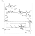
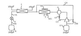
- FIG. 1A shows a refrigerant circuit configuration and the like of the refrigeration cycle apparatus 100 according to Embodiment 1.
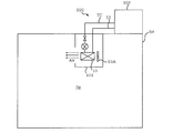
- FIG. 1B is a schematic diagram of first compressor 1 provided in refrigeration cycle apparatus 100 according to Embodiment 1.
- FIG. 1C shows an installation example of the refrigeration cycle apparatus 100 according to Embodiment 1.
- the refrigeration cycle apparatus 100 includes an indoor unit 101 and an outdoor unit 102.
- the indoor unit 101 is provided in the building Bd as shown in FIG. 1C.
- the outdoor unit 102 is provided outside the building Bd.
- the indoor unit 101 and the outdoor unit 102 are connected via the refrigerant pipe 7C and the refrigerant pipe 11.
- a gas-liquid two-phase refrigerant flows through the refrigerant pipe 7C.
- a gas refrigerant flows through the refrigerant pipe 11.
- the refrigeration cycle apparatus 100 includes a first refrigerant circuit C1 and a second refrigerant circuit C2. That is, the refrigeration cycle apparatus 100 has a two-way refrigeration cycle.
- the first refrigerant circuit C1 corresponds to the first refrigeration cycle (low-source side refrigeration cycle)
- the second refrigerant circuit C2 corresponds to the second refrigeration cycle (high-source side refrigeration cycle).
- the cooling capacity of the second refrigerant circuit C2 is lower than the cooling capacity of the first refrigerant circuit C1.
- the first refrigerant circuit C1 and the second refrigerant circuit C2 are independent refrigerant circuits.
- the first refrigerant circulating in the first refrigerant circuit C1 and the second refrigerant circulating in the second refrigerant circuit C2 may be the same type or different types.
- the first refrigerant is a carbon dioxide refrigerant.
- the carbon dioxide refrigerant is a refrigerant having a low global warming potential and a small environmental load.
- carbon dioxide refrigerant has a high operating pressure.
- a carbon dioxide refrigerant can also be adopted as the second refrigerant.
- the refrigeration cycle apparatus 100 corresponds to, for example, a refrigeration apparatus that stores stored items and the like, an air conditioner that cools an air-conditioning target space, and the like. In Embodiment 1, description will be made assuming that the refrigeration cycle apparatus 100 is a refrigeration apparatus.
- the refrigeration cycle apparatus 100 includes a control device Cnt.
- the refrigeration cycle apparatus 100 includes a first blower 3A, a second blower 10A, and a blower 15A.
- the refrigeration cycle apparatus 100 includes a condenser temperature sensor SE1, an evaporator temperature sensor SE2, and a pressure sensor SE3.
- the first refrigerant circuit C1 includes the first compressor 1, the oil separator 2, the first heat exchanger 3, the first refrigerant flow path of the second heat exchanger 4, and the first The expansion device 5, the liquid receiver 6, the valve 8, the expansion device 9, the third heat exchanger 10, and the accumulator 12 are included.
- the first refrigerant circuit C1 includes an oil return circuit C3.
- the oil return circuit C3 includes a pipe Rp1 that connects the oil separator 2 and the first compressor 1, and an opening / closing device 13 provided in the pipe Rp1.
- the first refrigerant circuit C1 includes a refrigerant pipe 7A, a refrigerant pipe 7B, a refrigerant pipe 7C, and a refrigerant pipe 11.
- the first refrigerant flows through the first refrigerant circuit C1.
- the first refrigerant circuit C1 includes the first compressor 1, the oil separator 2, the first heat exchanger 3, the first refrigerant flow path of the second heat exchanger 4, the first expansion device 5,
- the first refrigerant flows in the order of the liquid receiver 6, the valve 8, the expansion device 9, the third heat exchanger 10, and the accumulator 12.
- the refrigerant pipe 7 ⁇ / b> A connects the second heat exchanger 4 and the first expansion device 5.
- the refrigerant pipe 7B connects the first throttling device 5 and the liquid receiver 6.
- the refrigerant pipe 7 ⁇ / b> C connects the liquid receiver 6 and the valve 8.
- the refrigerant pipe 11 connects the third heat exchanger 10 and the accumulator 12.
- the refrigerant pipe 7 ⁇ / b> C and the refrigerant pipe 11 are pipes that connect the indoor unit 101 and the outdoor unit 102.
- the first refrigerant circuit C ⁇ b> 1 has a function of cooling the cooling target of the refrigeration cycle apparatus 100.
- the indoor unit 101 supplies cold air to the space SP in which the indoor unit 101 is provided. Thereby, the stored goods etc. which are provided in space SP are cooled.
- the space SP is, for example, a space in the building Bd for storing stored items in a frozen state.
- the second refrigerant circuit C ⁇ b> 2 includes the second compressor 14, the fourth heat exchanger 15, the second expansion device 16, and the second refrigerant flow path of the second heat exchanger 4. .
- the second refrigerant flows through the second refrigerant circuit C2.
- the second refrigerant circuit C ⁇ b> 2 includes the second compressor 14, the fourth heat exchanger 15, the second expansion device 16, and the second heat exchanger 4 in the order of the second refrigerant flow paths.
- the refrigerant is configured to flow.
- the second refrigerant circuit C2 cools the first refrigerant in the first refrigerant circuit C1 when the first refrigerant circuit C1 stops and the first compressor 1 has stopped. It has the function to do.
- the first compressor 1 compresses the first refrigerant to a high temperature and a high pressure.
- the first compressor 1 includes an airtight container 1A, a compression mechanism 1B, a stator 1C, a rotor 1D, a shaft 1E, a suction pipe 1F, and a discharge pipe 1G.
- the compression mechanism unit 1B includes a fixed scroll and a swing scroll. A compression chamber for compressing the first refrigerant is formed between the fixed scroll and the orbiting scroll.
- the stator 1C is fixed in the sealed container 1A. Refrigerating machine oil is stored at the bottom of the sealed container 1A.
- the refrigerating machine oil in the sealed container 1A is drawn into a flow path (not shown) in the shaft 1E as the shaft 1E rotates.
- the refrigerating machine oil drawn into the flow path in the shaft 1E is supplied to the compression mechanism unit 1B.
- a suction pipe 1F, a discharge pipe 1G, and a pipe Rp1 of an oil return circuit C3 are connected to the sealed container 1A.
- the suction portion of the first compressor 1 corresponds to the suction pipe 1F or the refrigerant pipe connected to the suction pipe 1F.
- the refrigerating machine oil stored in the oil separator 2 is returned from the pipe Rp1 into the sealed container 1A.
- the second compressor 14 compresses the second refrigerant to a high temperature and a high pressure.
- the oil separator 2 stores the refrigeration oil discharged from the first compressor 1 together with the refrigerant.
- the refrigerating machine oil stored in the oil separator 2 is returned to the first compressor 1 via the oil return circuit C3.
- the oil return circuit C3 has one end connected to the oil separator 2 and the other end connected to the first compressor 1.
- the oil return circuit C3 connects the oil separator 2 and the first compressor 1, and returns the refrigeration oil stored in the oil separator 2 to the first compressor 1.
- first heat exchanger 3 One side of the first heat exchanger 3 is connected to the oil separator 2 via the refrigerant pipe, and the other side is connected to the second heat exchanger 4 via the refrigerant pipe.
- the first heat exchanger 3 is provided with a first blower 3A. In the first heat exchanger 3, the air and the first refrigerant exchange heat.
- the second heat exchanger 4 includes a first refrigerant channel and a second refrigerant channel.
- the second heat exchanger 4 is a cascade heat exchanger.
- the second heat exchanger 4 is configured to exchange heat between the first refrigerant flowing through the first refrigerant flow path and the second refrigerant flowing through the second refrigerant flow path.
- One of the first refrigerant flow paths of the second heat exchanger 4 is connected to the first heat exchanger 3 via a refrigerant pipe, and the other is connected to the first expansion device 5 via a refrigerant pipe 7A. Has been.
- One of the second refrigerant flow paths of the second heat exchanger 4 is connected to the second expansion device 16 via the refrigerant pipe, and the other is sucked in the refrigerant of the second compressor 14 via the refrigerant pipe. Connected to the department.
- the first throttling device 5 and throttling device 9 can be constituted by electromagnetic valves whose opening degree can be controlled. Moreover, a capillary tube can also be employ
- the liquid receiver 6 has a function of storing a liquid refrigerant.
- the liquid receiver 6 is provided on the downstream side of the condenser. That is, the liquid receiver 6 is provided on the downstream side of the first refrigerant flow path of the second heat exchanger that functions as a condenser.
- the valve 8 can be constituted by, for example, an electromagnetic valve that can control opening and closing. The valve 8 is provided in the indoor unit 101.
- One of the third heat exchangers 10 is connected to the expansion device 9 via the refrigerant pipe, and the other is connected to the accumulator 12 via the refrigerant pipe.
- the third heat exchanger 10 is provided with a second blower 10A. In the third heat exchanger 10, the air and the first refrigerant exchange heat. The air cooled by the third heat exchanger 10 is supplied to the air-conditioning target space.
- the fourth heat exchanger 15 is connected to the second compressor 14 via the refrigerant pipe, and the other end is connected to the second expansion device 16 via the refrigerant pipe.
- the fourth heat exchanger 15 is provided with a blower 15A.
- the second expansion device 16 can be configured by an electromagnetic valve that can control the opening degree.
- a capillary tube may be employed for the second diaphragm device 16.
- the 1st heat exchanger 3 and the 4th heat exchanger 15 demonstrated as an example the aspect which heat-exchanges a refrigerant
- the first heat exchanger 3 and the fourth heat exchanger 15 may be in a mode in which heat exchange is performed between the refrigerant and a heat medium other than air. That is, a heat medium circuit independent of the first refrigerant circuit C1 and the second refrigerant circuit C2 may be connected to the first heat exchanger 3 and the fourth heat exchanger 15.
- water, brine, a refrigerant, or the like can be employed as the heat medium.
- a pump that conveys water and brine can be employed instead of the first blower 3A and the blower 15A that supply air.
- a compressor that compresses the refrigerant can be employed instead of the first blower 3A and the blower 15A that supply air.
- FIG. 1D is a functional block diagram of control device Cnt of refrigeration cycle apparatus 100 according to Embodiment 1. With reference to FIG. 1D, the 1st control which the refrigerating-cycle apparatus 100 implements, the structure of control apparatus Cnt, etc. are demonstrated.
- the control device Cnt acquires information on the temperature detected by the condenser temperature sensor SE1, information on the temperature detected by the evaporator temperature sensor SE2, and information on the pressure detected by the pressure sensor SE3.
- the condenser temperature sensor SE1 corresponds to the first temperature sensor of the present invention
- the evaporator temperature sensor SE2 corresponds to the second temperature sensor of the present invention.
- the control device Cnt The compressor 14 has a function of starting the operation of the compressor 14 and performing the first control to open the switchgear 13.
- the user may turn off the power of the refrigeration cycle apparatus 100.
- the temperature of the refrigerant pipe 11 in which the first refrigerant in a gas state is sealed is likely to rise.
- the refrigeration cycle apparatus 100 is configured to supply power when the first compressor 1 and the second compressor 14 are stopped and the pressure in the low-pressure portion of the first refrigerant circuit C1 is equal to or higher than a reference value. Even if is turned OFF, the operation of the second compressor 14 is automatically started.
- the control device Cnt also operates the blower 15A, and the second expansion device 16 has a predetermined opening.
- the second refrigerant in the second refrigerant circuit C2 cools the first refrigerant in the first refrigerant circuit C1, and an increase in the pressure of the first refrigerant is suppressed.
- the second refrigerant in the second refrigerant circuit C2 cools the first refrigerant in the first refrigerant circuit C1
- the first refrigerant naturally circulates through the first refrigerant circuit C1. That is, the conveyance capacity of the first refrigerant at this time is smaller than the conveyance capacity of the first refrigerant when the first compressor 1 is operating.
- the opening / closing device 13 is opened in synchronization with the start of the operation of the second compressor 14.
- the first control may have the following contents in terms of implementation conditions and configuration.
- the control device Cnt stops the first blower 3A and the second blower 10A.
- the first control is performed.
- the condition that the detected temperature of the first heat exchanger 3 is equal to or higher than the detected temperature of the third heat exchanger 10 is that the first refrigerant is supplied to the first heat exchanger 3 while the first blower 3A is operated. This is a condition where it is unlikely that the first refrigerant can be liquefied even if it is passed through. For example, when the outside air temperature is high as in summer, the temperature of the first heat exchanger 3 provided in the outdoor unit 102 also becomes high.
- the refrigeration cycle apparatus 100 stops the first blower 3A in order to suppress power consumption. Further, the second blower 10A is also stopped. This is because, if the second blower 10A is operated, gasification of the first refrigerant is promoted, and the pressure of the first refrigerant increases.
- the first control may have the following contents in terms of implementation conditions and configuration.
- the control device Cnt does not perform the first control and stops the second compressor 14
- the 2nd control which operates 3A of 1st blowers and the 2nd blower in the state made to carry out is carried out.
- the condition that the detected temperature of the first heat exchanger 3 is lower than the detected temperature of the third heat exchanger 10 is that the first refrigerant is supplied to the first heat exchanger 3 while the first blower 3A is operated. This is a condition where there is a possibility that the first refrigerant can be liquefied by passing.
- the temperature of the first heat exchanger 3 provided in the outdoor unit 102 is also low. Therefore, if the first blower 3A is operated and air is supplied to the first heat exchanger 3, the first refrigerant is liquefied and an increase in the pressure of the first refrigerant can be suppressed.
- the second blower 10A is in a stopped state. This is because, if the second blower 10A is operated, gasification of the first refrigerant is promoted, and the pressure of the first refrigerant increases.
- the refrigeration cycle apparatus 100 receives power supply from another system and performs various operations.
- the control device Cnt includes a determination unit 90A, an operation control unit 90B, and a storage unit 90C.
- the determination unit 90A has a function of determining whether or not the pressure in the low-pressure part of the first refrigerant circuit C1 is equal to or higher than a reference value.
- the low pressure part of the first refrigerant circuit C1 refers to, for example, the downstream side of the expansion device 9 and the upstream side of the suction part of the first compressor 1. That is, the low pressure portion of the first refrigerant circuit C1 indicates a portion where the refrigerant decompressed by the expansion device flows.
- the determination unit 90 A of determination parts determine whether the pressure of the low voltage
- the outside air temperature or the like may be used instead of the pressure sensor SE3. This is because there is a correlation between the outside air temperature and the first refrigerant circuit C1.
- the determination unit 90 ⁇ / b> A has a function of determining whether or not the detected temperature of the first heat exchanger 3 is equal to or higher than the detected temperature of the third heat exchanger 10. Furthermore, the determination unit 90 ⁇ / b> A has a function of determining whether or not the detected temperature of the first heat exchanger 3 is lower than the detected temperature of the third heat exchanger 10.
- the operation control unit 90 ⁇ / b> B controls the rotational speed of the first compressor 1 and the rotational speed of the second compressor 14. Further, when the first throttle device 5, the throttle device 9 and the second throttle device 16 are solenoid valves, the operation control unit 90 ⁇ / b> B opens the opening of the first throttle device 5 and the opening of the throttle device 9. And the opening degree of the 2nd expansion device 16 is controlled.
- the operation control unit 90B controls the fan rotation speed of the first blower 3A, the fan rotation speed of the second blower 10A, and the fan rotation speed of the blower 15A.
- the operation control unit 90 ⁇ / b> B controls opening / closing of the valve 8 and opening / closing of the opening / closing device 13.
- the operation control unit 90B performs the first control.
- the operation control unit 90B includes the first fan 3A and the second fan The first control is performed in a state where the blower 10A is stopped.
- the operation control unit 90B does not perform the first control, The second control is performed.
- Each functional unit included in the control device Cnt is configured with dedicated hardware or MPU (Micro Processing Unit) that executes a program stored in a memory.
- MPU Micro Processing Unit
- the control device Cnt is, for example, a single circuit, a composite circuit, an ASIC (application-specific integrated circuit), an FPGA (field-programmable gate array), or a combination thereof. Applicable.
- Each functional unit realized by the control device Cnt may be realized by individual hardware, or each functional unit may be realized by one piece of hardware.
- each function executed by the control device Cnt is realized by software, firmware, or a combination of software and firmware. Software and firmware are described as programs and stored in a memory.
- the MPU implements each function of the control device Cnt by reading and executing a program stored in the memory.
- the memory is a nonvolatile or volatile semiconductor memory such as a RAM, a ROM, a flash memory, an EPROM, or an EEPROM.
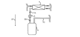
- FIG. 1E is an explanatory diagram of the positional relationship between the second heat exchanger 4 and the liquid receiver 6.
- the Z direction in FIG. 1E is the direction of gravity.
- the liquid receiver 6 is disposed below the second heat exchanger 4.
- the first refrigerant liquefied by the second heat exchanger 4 quickly flows into the liquid receiver 6.
- the conveyance capacity of the 1st refrigerant is small compared with the conveyance capacity of the 1st refrigerant when the 1st compressor 1 is operating.
- the liquid receiver 6 is disposed below the second heat exchanger 4 so that the liquefied first refrigerant quickly flows into the liquid receiver 6.
- the refrigerant pipe 7A and the refrigerant pipe 7B are configured so that the first refrigerant liquefied by the second heat exchanger 4 can easily flow into the liquid receiver 6. That is, the configuration of the refrigerant pipe 7A and the refrigerant pipe 7B is such that when the first refrigerant flows from the second heat exchanger 4 to the liquid receiver 6, the first refrigerant flows, for example, from the lower side to the upper side. Absent.
- Embodiment 1 (Normal Operation)
- the first refrigerant in the first refrigerant circuit C1 When the first refrigerant in the first refrigerant circuit C1 is discharged from the first compressor 1, it flows into the first heat exchanger 3.
- the first refrigerant that has flowed into the first heat exchanger 3 radiates heat to the air supplied from the first blower 3A.
- the first refrigerant flowing out from the first heat exchanger 3 flows into the second heat exchanger 4.
- the first refrigerant of the second heat exchanger 4 is cooled to the second refrigerant.
- coolant which flowed out from the 2nd heat exchanger 4 is pressure-reduced by the 1st expansion device 5, and temperature and pressure fall.
- the first refrigerant that has flowed out of the first expansion device 5 flows into the third heat exchanger 10.
- the first refrigerant flowing into the third heat exchanger 10 absorbs heat from the air supplied from the second blower 10A, and cools the air.
- the first refrigerant that has flowed out of the third heat exchanger 10 flows into the accumulator 12.
- the first refrigerant that has flowed out of the accumulator 12 is sucked into the first compressor 1.
- the second refrigerant in the second refrigerant circuit C2 When the second refrigerant in the second refrigerant circuit C2 is discharged from the second compressor 14, it flows into the fourth heat exchanger 15.
- the second refrigerant flowing into the fourth heat exchanger 15 radiates heat to the air supplied from the blower 15A.
- coolant which flowed out from the 4th heat exchanger 15 is pressure-reduced with the 2nd expansion device 16, and temperature and pressure fall.
- the second refrigerant flowing out from the first expansion device 5 flows into the second heat exchanger 4 and cools the first refrigerant. Thereby, a supercooling degree can be given to the 1st refrigerant.
- coolant which flowed into 1 A of airtight containers flows in into the oil separator 2 via piping Rp1 and the switchgear 13. Then, the first refrigerant that has flowed into the oil separator 2 flows into the second heat exchanger 4 via the first heat exchanger 3.
- coolant which flowed into the 2nd heat exchanger 4 is cooled by the 2nd refrigerant
- the first refrigerant in the gas-liquid two-phase state flows into the liquid receiver 6 through the refrigerant pipe 7A and the first expansion device 5.
- the liquid refrigerant of the first refrigerant is stored in the receiver 6, and the gas refrigerant of the first refrigerant flows into the third heat exchanger 10 through the refrigerant pipe 7 ⁇ / b> C, the valve 8, and the expansion device 9. To do.
- the first refrigerant circulates in the first refrigerant circuit C1
- the first refrigerant is cooled to the second refrigerant of the second heat exchanger 4, and the liquid refrigerant stored in the liquid receiver 6 increases. I will do it. In this way, an increase in the pressure of the first refrigerant in the first refrigerant circuit is suppressed.
- FIG. 1F is an explanatory diagram of effects of the refrigeration cycle apparatus 100 according to Embodiment 1.
- the horizontal axis of the graph shown in FIG. 1F indicates the cooling capacity of the refrigeration cycle apparatus, and the vertical axis indicates the pressure of the first refrigerant circuit.
- a curve L1 in the graph shown in FIG. 1F indicates the cooling capacity of the conventional refrigeration cycle apparatus.
- a curve L2 in the graph shown in FIG. 1F indicates the cooling capacity of the refrigeration cycle apparatus 100.
- a curve L3 in the graph shown in FIG. 1F indicates the pressure reference value described above. As shown in FIG.
- the pressure of the first refrigerant circuit is improved even when the cooling capacity is improved, that is, when the rotation speed of the second compressor of the second refrigerant circuit is increased. Is not lower than the reference value of the low-pressure part.
- the opening / closing device 13 is opened, so that the circulation amount (flow rate) of the first refrigerant in the first refrigerant circuit C1 increases. Therefore, the first refrigerant can be efficiently cooled by the second refrigerant, and the increase in the rotational speed of the second compressor 14 can be suppressed. That is, the refrigeration cycle apparatus 100 can suppress an increase in the pressure of the refrigerant in the first refrigerant circuit (low source circuit) while suppressing power consumption.
- FIG. 1G is a modification of the refrigeration cycle apparatus 100 according to Embodiment 1.
- the refrigeration cycle apparatus 100 is supplied with power from another system when a power failure occurs.
- the power used for the refrigeration cycle apparatus 100 is supplied from the power storage unit Bt, not from another system.
- the power storage unit Bt is a battery.
- the modification of the first embodiment is configured to be able to receive power supply from power storage unit Bt. That is, the modification of the first embodiment includes the power storage unit Bt that supplies power to the second compressor 14. The power storage unit Bt supplies power to the outdoor unit 102, the indoor unit 101, and the control device Cnt.
- Embodiment 2 FIG. Next, the second embodiment will be described with reference to the drawings. Description of parts common to those of the first embodiment will be omitted, and different parts will be mainly described.
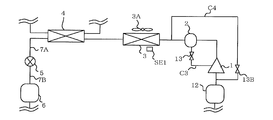
- FIG. 2A is a configuration explanatory diagram of a refrigeration cycle apparatus 200 according to Embodiment 2.
- FIG. 2B is a functional block diagram of control device Cnt of refrigeration cycle apparatus 200 according to Embodiment 2.
- the refrigeration cycle apparatus 200 includes a bypass circuit C4 in addition to the oil return circuit C3.
- the bypass circuit C4 includes a pipe Rp2 that connects the first refrigerant discharge section of the first compressor 1 and the first refrigerant suction section of the first compressor 1, and an open / close provided in the pipe Rp2. And a device 13B.
- the pipe Rp2 of the bypass circuit C4 bypasses the first compressor 1.
- the pipe Rp2 of the bypass circuit C4 has one end connected to the first refrigerant suction portion of the first compressor 1 and the other connected to the first refrigerant discharge portion of the first compressor 1. Including ends.
- the control device Cnt controls the opening / closing of the opening / closing device 13B.
- the control device Cnt When executing the first control, the control device Cnt opens the opening / closing device 13B in addition to the opening / closing device 13. Note that when the first control is executed, the control device Cnt may not open the switchgear 13 but open the switchgear 13B.
- the switchgear 13 corresponds to the first switchgear of the present invention
- the switchgear 13B corresponds to the second switchgear of the present invention.
- the refrigeration cycle apparatus 200 according to Embodiment 2 has the following effects in addition to the same effects as the refrigeration cycle apparatus 100 according to Embodiment 1.
- the bypass circuit C4 bypasses the first compressor 1.
- the flow path of the bypass circuit C4 is easier for the first refrigerant to pass than the flow path from the suction portion of the first compressor 1 to the inlet of the oil return circuit C3. That is, since the refrigeration cycle apparatus 200 according to Embodiment 2 includes the bypass circuit C4, the first refrigerant is likely to naturally circulate through the first refrigerant circuit C1 of the refrigeration cycle apparatus 200 according to Embodiment 2.
- a bypass circuit C4 is further provided.
- the control device Cnt When executing the first control, the control device Cnt opens the opening / closing device 13B in addition to the opening / closing device 13. Thereby, the circulation amount (flow rate) of the first refrigerant in the first refrigerant circuit C1 can be further increased. Therefore, the first refrigerant can be more efficiently cooled by the second refrigerant, and the increase in the rotational speed of the second compressor 14 can be further suppressed. That is, the refrigeration cycle apparatus 200 can suppress an increase in the refrigerant pressure in the first refrigerant circuit (low-source circuit) while further suppressing power consumption.
- FIG. 2C is Modification 1 of the refrigeration cycle apparatus 200 according to Embodiment 2.
- the bypass circuit C4 has one end connected to the first refrigerant suction portion of the first compressor 1, and the other end connected between the oil separator 2 and the first heat exchanger 3. It is also possible to include this. Even in the refrigeration cycle apparatus 200 of the first modification, the same effects as those of the first and second embodiments can be obtained.
- FIG. 2D is a second modification of the refrigeration cycle apparatus 200 according to the second embodiment.
- the bypass circuit C4 has one end connected to the first refrigerant suction portion of the first compressor 1, the first refrigerant flow of the first heat exchanger 3 and the second heat exchanger 4.
- the aspect containing the other end connected between the paths may be sufficient. Even in the refrigeration cycle apparatus 200 according to the second modification, the same effects as those in the first and second embodiments can be obtained.
- the modification of the first embodiment can be applied to the second embodiment, the first modification of the second embodiment, and the second modification of the second embodiment.
Abstract
冷凍サイクル装置は、第1の圧縮機、油分離器、凝縮器として機能する第1の熱交換器、第2の熱交換器の第1の冷媒流路、第1の絞り装置、及び蒸発器として機能する第3の熱交換器を含み、第1の冷媒が流れる第1の冷媒回路と、第2の圧縮機、凝縮器として機能する第4の熱交換器、第2の絞り装置、及び第2の熱交換器の第2の冷媒流路を含み、第2の冷媒が流れる第2の冷媒回路と、第1の開閉装置を含み、油分離器と第1の圧縮機とを接続し、油分離器に貯留されている冷凍機油を第1の圧縮機に戻す油戻し回路と、第1の圧縮機、第2の圧縮機、第1の絞り装置、第2の絞り装置、及び第1の開閉装置を制御する制御装置と、を備え、制御装置は、第1の圧縮機及び第2の圧縮機が停止しており、且つ、第1の冷媒回路の低圧部の圧力が基準値以上になった場合には、第2の圧縮機の運転を開始し、第1の開閉装置を開く第1の制御を実施するものである。
Description
本発明は、複数の冷媒回路を含む冷凍サイクル装置に関するものである。
従来から、圧縮機、カスケード熱交換器、受液部、絞り装置、及び蒸発器を含む低元回路と、圧縮機、凝縮器、絞り装置、熱交換部及びカスケード熱交換器を含む高元回路とを備えた冷凍サイクル装置が提案されている(例えば、特許文献1参照)。低元回路の蒸発器が空調対象空間の冷却等に用いられる。また、カスケード熱交換器は、高元回路の冷媒が低元回路の冷媒を冷却する。更に、受液部には熱交換部が設けられている。このため、低元回路の冷媒は受液部の冷媒によって冷却される。
低元回路の圧縮機が例えば停電等により停止する場合がある。低元回路の圧縮機が停止すると、低元回路の冷媒が循環しなくなる。そうすると、低元回路のガス冷媒が低元回路の蒸発器で冷却されなくなり、その一方で、低元回路のガス冷媒は外気によって加熱される場合がある。その結果、低元回路のガス冷媒の圧力が上昇することがある。ガス冷媒の圧力の上昇は、例えば二酸化炭素冷媒のような高圧冷媒を採用するほど、顕著である。また、ガス冷媒の圧力の上昇は、例えば夏期のように外気温度が高いほど、顕著である。このような、ガス冷媒の圧力の上昇に備える手段としては、例えばガス冷媒が流れる配管の耐圧を向上させる手段がある。しかし、配管の耐圧を向上させる手段では、配管コストが増大してしまう。
特許文献1に記載の冷凍サイクル装置は、低元回路の圧縮機が停止した場合には、高元回路の圧縮機の運転を開始する。これにより、カスケードコンデンサ及び受液部では、高元回路の冷媒が低元回路の冷媒を冷却する。このように、特許文献1に記載の冷凍サイクル装置では、低元回路の冷媒を冷却し、低元回路の圧力の上昇を抑制している。
特許文献1の冷凍サイクル装置では、低元回路の圧縮機が停止した場合であっても、低元回路の冷媒が自然循環し、低元回路の冷媒が高元回路の冷媒により冷却される。ここで、低元回路の圧縮機が停止している状態では、冷媒が低元回路の圧縮機を通過しにくい場合がある。圧縮機が例えばスクロール圧縮機であれば、圧縮機の冷媒の吸入管に至った冷媒は、固定スクロールと揺動スクロールとの間を抜けなければ、圧縮機の吐出管に到達できない。低元回路の圧縮機を冷媒が通過しにくいと、冷媒を自然循環させるときの冷媒の流量が低下してしまう。この流量が低下してしまうと、高元回路の圧縮機の回転数を大幅に増大させないと、低元回路の冷媒の冷却が不十分になり、低元回路の圧力の上昇を抑制できなくなる可能性がある。つまり、特許文献1の冷凍サイクル装置では、低元回路の圧力の上昇を抑制するために、高元回路での消費電力が増大してしまう、という課題がある。
本発明は、従来技術における上記課題を解決するためになされたものであり、消費電力を抑制しながら、第1の冷媒回路(低元回路)の冷媒の圧力の上昇を抑制することができる冷凍サイクル装置を提供することを目的としている。
本発明に係る冷凍サイクル装置は、第1の圧縮機、油分離器、凝縮器として機能する第1の熱交換器、第2の熱交換器の第1の冷媒流路、第1の絞り装置、及び蒸発器として機能する第3の熱交換器を含み、第1の冷媒が流れる第1の冷媒回路と、第2の圧縮機、凝縮器として機能する第4の熱交換器、第2の絞り装置、及び第2の熱交換器の第2の冷媒流路を含み、第2の冷媒が流れる第2の冷媒回路と、第1の開閉装置を含み、油分離器と第1の圧縮機とを接続し、油分離器に貯留されている冷凍機油を第1の圧縮機に戻す油戻し回路と、第1の圧縮機、第2の圧縮機、及び第1の開閉装置を制御する制御装置と、を備え、制御装置は、第1の圧縮機及び第2の圧縮機が停止しており、且つ、第1の冷媒回路の低圧部の圧力が基準値以上になった場合には、第2の圧縮機の運転を開始し、第1の開閉装置を開く第1の制御を実施するものである。
本発明に係る冷凍サイクル装置は、上記構成を備えているので、消費電力を抑制しながら、第1の冷媒回路(低元回路)の冷媒の圧力の上昇を抑制することができる。
本発明に係る冷凍サイクル装置の実施の形態を、図面に基づいて説明する。なお、以下に示す図面の形態によって本発明が限定されるものではなく、本発明の技術思想の範囲内において、適当な変更ならびに修正がなされうる。
実施の形態1.
図1Aは、実施の形態1に係る冷凍サイクル装置100の冷媒回路構成等を示している。
図1Bは、実施の形態1に係る冷凍サイクル装置100が備える第1の圧縮機1の模式図である。
図1Cは、実施の形態1に係る冷凍サイクル装置100の設置例を示している。
図1Aは、実施の形態1に係る冷凍サイクル装置100の冷媒回路構成等を示している。
図1Bは、実施の形態1に係る冷凍サイクル装置100が備える第1の圧縮機1の模式図である。
図1Cは、実施の形態1に係る冷凍サイクル装置100の設置例を示している。
[全体構成説明]
冷凍サイクル装置100は、室内ユニット101と、室外ユニット102とを備えている。室内ユニット101は、図1Cに示すように、建物Bdに設けられている。室外ユニット102は、建物Bdの外側に設けられている。室内ユニット101と室外ユニット102とは、冷媒配管7C及び冷媒配管11を介して接続されている。冷媒配管7Cは気液二相の冷媒が流れる。冷媒配管11はガス冷媒が流れる。
冷凍サイクル装置100は、室内ユニット101と、室外ユニット102とを備えている。室内ユニット101は、図1Cに示すように、建物Bdに設けられている。室外ユニット102は、建物Bdの外側に設けられている。室内ユニット101と室外ユニット102とは、冷媒配管7C及び冷媒配管11を介して接続されている。冷媒配管7Cは気液二相の冷媒が流れる。冷媒配管11はガス冷媒が流れる。
図1A、図1B及び図1Cに示すように、冷凍サイクル装置100は、第1の冷媒回路C1と、第2の冷媒回路C2とを備えている。つまり、冷凍サイクル装置100は、2元冷凍サイクルを有している。第1の冷媒回路C1が、第1の冷凍サイクル(低元側冷凍サイクル)に対応し、第2の冷媒回路C2が、第2の冷凍サイクル(高元側冷凍サイクル)に対応する。第2の冷媒回路C2の冷却能力は第1の冷媒回路C1の冷却能力よりも低い。第1の冷媒回路C1と第2の冷媒回路C2とは、独立した冷媒回路になっている。第1の冷媒回路C1を循環する第1の冷媒と、第2の冷媒回路C2を循環する第2の冷媒とは、同じ種類のものでもよいし、別の種類のものでもよい。実施の形態1では、第1の冷媒は二酸化炭素冷媒である。二酸化炭素冷媒は、地球温暖化係数が低く、環境負荷が小さい冷媒である。一方、二酸化炭素冷媒は、動作圧力が高い。第2の冷媒にも二酸化炭素冷媒を採用することができる。冷凍サイクル装置100は、例えば、貯蔵品等を貯蔵する冷凍装置、及び、空調対象空間を冷却する空気調和装置等が該当する。実施の形態1では、冷凍サイクル装置100が冷凍装置であるものとして説明する。
冷凍サイクル装置100は、制御装置Cntを備えている。また、冷凍サイクル装置100は、第1の送風機3Aと、第2の送風機10Aと、送風機15Aとを備えている。また、冷凍サイクル装置100は、凝縮器温度センサーSE1と、蒸発器温度センサーSE2と、圧力センサーSE3とを備えている。
第1の冷媒回路C1は、第1の圧縮機1と、油分離器2と、第1の熱交換器3と、第2の熱交換器4の第1の冷媒流路と、第1の絞り装置5と、受液器6と、弁8と、絞り装置9と、第3の熱交換器10と、アキュムレータ12とを含む。また、第1の冷媒回路C1は、油戻し回路C3を含んでいる。油戻し回路C3は、油分離器2と第1の圧縮機1とを接続する配管Rp1と、この配管Rp1に設けられている開閉装置13とを備えている。更に、第1の冷媒回路C1は、冷媒配管7Aと、冷媒配管7Bと、冷媒配管7Cと、冷媒配管11とを含む。第1の冷媒回路C1には、第1の冷媒が流れる。第1の冷媒回路C1は、第1の圧縮機1、油分離器2、第1の熱交換器3、第2の熱交換器4の第1の冷媒流路、第1の絞り装置5、受液器6、弁8、絞り装置9、第3の熱交換器10、及びアキュムレータ12の順番に第1の冷媒が流れるように構成されている。冷媒配管7Aは第2の熱交換器4と第1の絞り装置5とを接続する。冷媒配管7Bは第1の絞り装置5と受液器6とを接続する。冷媒配管7Cは受液器6と弁8とを接続している。冷媒配管11は第3の熱交換器10とアキュムレータ12とを接続している。冷媒配管7C及び冷媒配管11は室内ユニット101と室外ユニット102とを接続する配管である。第1の冷媒回路C1は、冷凍サイクル装置100の冷却対象を冷却する機能を有する。実施の形態1では、室内ユニット101は、室内ユニット101が設けられている空間SPに冷気を供給する。これにより、空間SPに設けられている貯蔵品等が冷却される。ここで、空間SPは、貯蔵品を冷凍保存する例えば建物Bd内の空間である。
第2の冷媒回路C2は、第2の圧縮機14と、第4の熱交換器15と、第2の絞り装置16と、第2の熱交換器4の第2の冷媒流路とを含む。第2の冷媒回路C2には、第2の冷媒が流れる。第2の冷媒回路C2は、第2の圧縮機14、第4の熱交換器15、第2の絞り装置16及び第2の熱交換器4の第2の冷媒流路の順番に第2の冷媒が流れるように構成されている。第2の冷媒回路C2は、第1の冷媒回路C1の過冷却をつける機能、及び、第1の圧縮機1が停止してしまったときに第1の冷媒回路C1の第1の冷媒を冷却する機能を有する。
第1の圧縮機1は、第1の冷媒を圧縮し、高温及び高圧にする。第1の圧縮機1がスクロール圧縮機である場合を一例に説明する。第1の圧縮機1は密閉容器1Aと、圧縮機構部1Bと、ステーター1Cと、ローター1Dと、シャフト1Eと、吸入管1Fと、吐出管1Gとを備えている。圧縮機構部1Bは、固定スクロール及び揺動スクロールを含む。固定スクロールと揺動スクロールとの間には、第1の冷媒を圧縮する圧縮室が形成されている。ステーター1Cは密閉容器1A内に固定されている。密閉容器1Aの底部には、冷凍機油が貯留されている。密閉容器1Aの冷凍機油は、シャフト1Eが回転することで、シャフト1E内の流路(図示省略)に引き込まれる。シャフト1E内の流路に引き込まれた冷凍機油は、圧縮機構部1Bに供給される。密閉容器1Aには、吸入管1Fと、吐出管1Gと、油戻し回路C3の配管Rp1とが接続されている。第1の圧縮機1の吸入部は、吸入管1F又は吸入管1Fに接続されている冷媒配管に対応する。第1の圧縮機1の吐出部は、吐出管1G又は吐出管1Gに接続されている冷媒配管に対応する。油分離器2に貯留されている冷凍機油は、配管Rp1から密閉容器1A内に戻される。第2の圧縮機14は、第2の冷媒を圧縮し、高温及び高圧にする。油分離器2は、第1の圧縮機1から冷媒とともに吐出された冷凍機油を貯留する。油分離器2に貯留されている冷凍機油は、油戻し回路C3を介して、第1の圧縮機1に戻される。油戻し回路C3は、一端が油分離器2に接続され、他端が第1の圧縮機1に接続されている。油戻し回路C3は油分離器2と第1の圧縮機1とを接続し、油分離器2に貯留されている冷凍機油を第1の圧縮機1に戻す。
第1の熱交換器3は、一方が冷媒配管を介して油分離器2に接続され、他方が冷媒配管を介して第2の熱交換器4に接続されている。第1の熱交換器3には第1の送風機3Aが付設されている。第1の熱交換器3では、空気と第1の冷媒とが熱交換する。
第2の熱交換器4は、第1の冷媒流路及び第2の冷媒流路を含む。第2の熱交換器4はカスケード熱交換器である。第2の熱交換器4は、第1の冷媒流路を流れる第1の冷媒と、第2の冷媒流路を流れる第2の冷媒とが熱交換できるように構成されている。第2の熱交換器4の第1の冷媒流路は、一方が冷媒配管を介して第1の熱交換器3に接続され、他方が冷媒配管7Aを介して第1の絞り装置5に接続されている。第2の熱交換器4の第2の冷媒流路は、一方が冷媒配管を介して第2の絞り装置16に接続され、他方が冷媒配管を介して第2の圧縮機14の冷媒の吸入部に接続されている。
第1の絞り装置5及び絞り装置9は、開度を制御できる電磁弁で構成することができる。また、第1の絞り装置5及び絞り装置9には、毛細管を採用することもできる。受液器6は、液冷媒を貯留する機能を有している。受液器6は、凝縮器よりも下流側に設けられている。つまり、受液器6は、凝縮器として機能する第2の熱交換器の第1の冷媒流路よりも下流側に設けられている。弁8は、例えば開閉を制御することができる電磁弁で構成することができる。弁8は、室内ユニット101に設けられている。
第3の熱交換器10は、一方が冷媒配管を介して絞り装置9に接続され、他方が冷媒配管を介してアキュムレータ12に接続されている。第3の熱交換器10には第2の送風機10Aが付設されている。第3の熱交換器10では、空気と第1の冷媒とが熱交換する。第3の熱交換器10で冷却された空気は、空調対象空間に供給される。
第4の熱交換器15は、一方が冷媒配管を介して第2の圧縮機14に接続され、他方が冷媒配管を介して第2の絞り装置16に接続されている。第4の熱交換器15には送風機15Aが付設されている。第4の熱交換器15では、空気と第2の冷媒とが熱交換する。第2の絞り装置16は、開度を制御できる電磁弁で構成することができる。また、第2の絞り装置16には、毛細管を採用することもできる。
なお、第1の熱交換器3及び第4の熱交換器15は、冷媒(第1の冷媒及び第2の冷媒)と空気とが熱交換する態様を一例として説明したが、それに限定されるものではない。第1の熱交換器3及び第4の熱交換器15は、冷媒と空気以外の熱媒体とが熱交換する態様であってもよい。つまり、第1の熱交換器3及び第4の熱交換器15には、第1の冷媒回路C1及び第2の冷媒回路C2とは独立した熱媒体回路が接続されていてもよい。熱媒体には、例えば、水、ブライン、冷媒等を採用することができる。なお、熱媒体が水及びブラインである場合には、空気を供給する第1の送風機3A及び送風機15Aの代わりに、水及びブラインを搬送するポンプを採用することができる。また、熱媒体が冷媒である場合には、空気を供給する第1の送風機3A及び送風機15Aの代わりに、冷媒を圧縮する圧縮機を採用することができる。
[制御装置Cntの説明]
図1Dは、実施の形態1に係る冷凍サイクル装置100の制御装置Cntの機能ブロック図である。図1Dを参照して、冷凍サイクル装置100が実施する第1の制御、及び、制御装置Cntの構成等について説明する。
図1Dは、実施の形態1に係る冷凍サイクル装置100の制御装置Cntの機能ブロック図である。図1Dを参照して、冷凍サイクル装置100が実施する第1の制御、及び、制御装置Cntの構成等について説明する。
制御装置Cntは、凝縮器温度センサーSE1の検出温度の情報と、蒸発器温度センサーSE2の検出温度の情報と、圧力センサーSE3の検出圧力の情報とを取得する。凝縮器温度センサーSE1が本発明の第1の温度センサーに対応し、蒸発器温度センサーSE2が本発明の第2の温度センサーに対応している。
制御装置Cntは、第1の圧縮機1及び第2の圧縮機14が停止しており、且つ、第1の冷媒回路C1の低圧部の圧力が基準値以上になった場合には、第2の圧縮機14の運転を開始し、開閉装置13を開く第1の制御を実施する機能を有している。第1の圧縮機1及び第2の圧縮機14が停止する場合には、例えばユーザーが冷凍サイクル装置100の電源をOFFした場合がある。夏期等のように外気温度が高い季節では、ガス状態になっている第1の冷媒が封入されている冷媒配管11の温度が上昇しやすい。その結果、冷媒配管11の第1の冷媒の圧力が基準値以上に上昇し、冷媒配管11が破損等してしまう可能性が高まる。また、このような破損等を防止するために、冷媒配管11の耐圧を向上させたとしても、配管コストが増大してしまう。そこで、冷凍サイクル装置100は、第1の圧縮機1及び第2の圧縮機14が停止し、且つ、第1の冷媒回路C1の低圧部の圧力が基準値以上になった場合には、電源がOFFになっていても、第2の圧縮機14の運転を自動的に開始する。なお、制御装置Cntは、送風機15Aも運転し、第2の絞り装置16は予め定められた開度とする。これにより、第2の熱交換器では、第2の冷媒回路C2の第2の冷媒が第1の冷媒回路C1の第1の冷媒を冷却し、第1の冷媒の圧力の上昇が抑制される。第2の冷媒回路C2の第2の冷媒が第1の冷媒回路C1の第1の冷媒を冷却しているとき、第1の冷媒は第1の冷媒回路C1を自然循環している。つまり、このときの第1の冷媒の搬送能力は、第1の圧縮機1が運転しているときの第1の冷媒の搬送能力と比較すると、小さい。このため、第1の圧縮機1を第1の冷媒が通過しにくい場合には、第1の冷媒の流量が低下してしまう。第1の冷媒の流量が低下してしまうと、第2の冷媒回路C2の第2の圧縮機14の回転数を上げて、冷却能力を増大させなければ、第1の冷媒回路C1の圧力の上昇を抑制できなくなる可能性がある。そこで、冷凍サイクル装置100では、第2の圧縮機14の運転の開始に同期して、開閉装置13を開く。これにより、第1の冷媒が第1の圧縮機1を通過しやすくなり、第1の冷媒が自然循環しているときであっても、第1の冷媒の流量が低下してしまうことを抑制することができる。
また、第1の制御は、実施の条件と、構成とが次のような内容であってもよい。
制御装置Cntは、第1の熱交換器3の検出温度が第3の熱交換器10の検出温度以上である場合には、第1の送風機3A及び第2の送風機10Aを停止させた状態で、第1の制御を実施する。第1の熱交換器3の検出温度が第3の熱交換器10の検出温度以上であるという条件は、第1の送風機3Aを運転した状態で第1の熱交換器3に第1の冷媒を通過させても、第1の冷媒を液化させることができる見込みが低い条件である。例えば夏期のように外気温度が高いと、室外ユニット102に設けられている第1の熱交換器3の温度も高くなる。したがって、第1の送風機3Aを運転して第1の熱交換器3に空気を供給しても、第1の冷媒が液化しない。そこで、冷凍サイクル装置100は、消費電力を抑制するために、第1の送風機3Aを停止する。また、第2の送風機10Aも停止させた状態とする。第2の送風機10Aを運転してしまうと、第1の冷媒のガス化が促され、第1の冷媒の圧力が上昇してしまうためである。
制御装置Cntは、第1の熱交換器3の検出温度が第3の熱交換器10の検出温度以上である場合には、第1の送風機3A及び第2の送風機10Aを停止させた状態で、第1の制御を実施する。第1の熱交換器3の検出温度が第3の熱交換器10の検出温度以上であるという条件は、第1の送風機3Aを運転した状態で第1の熱交換器3に第1の冷媒を通過させても、第1の冷媒を液化させることができる見込みが低い条件である。例えば夏期のように外気温度が高いと、室外ユニット102に設けられている第1の熱交換器3の温度も高くなる。したがって、第1の送風機3Aを運転して第1の熱交換器3に空気を供給しても、第1の冷媒が液化しない。そこで、冷凍サイクル装置100は、消費電力を抑制するために、第1の送風機3Aを停止する。また、第2の送風機10Aも停止させた状態とする。第2の送風機10Aを運転してしまうと、第1の冷媒のガス化が促され、第1の冷媒の圧力が上昇してしまうためである。
更に、第1の制御は、実施の条件と、構成とが次のような内容であってもよい。
制御装置Cntは、第1の熱交換器3の検出温度が第3の熱交換器10の検出温度よりも低い場合には、第1の制御を実施せず、第2の圧縮機14を停止させた状態で第1の送風機3A及び第2の送風機を運転する第2の制御を実施する。第1の熱交換器3の検出温度が第3の熱交換器10の検出温度よりも低いという条件は、第1の送風機3Aを運転した状態で第1の熱交換器3に第1の冷媒を通過させることで、第1の冷媒を液化させることができる見込みがある条件である。例えば冬期及び夜間のように外気温度が低いと、室外ユニット102に設けられている第1の熱交換器3の温度も低くなる。したがって、第1の送風機3Aを運転して第1の熱交換器3に空気を供給すれば、第1の冷媒が液化され、第1の冷媒の圧力の上昇を抑制することができる。なお、第2の送風機10Aは停止させた状態とする。第2の送風機10Aを運転してしまうと、第1の冷媒のガス化が促され、第1の冷媒の圧力が上昇してしまうためである。
制御装置Cntは、第1の熱交換器3の検出温度が第3の熱交換器10の検出温度よりも低い場合には、第1の制御を実施せず、第2の圧縮機14を停止させた状態で第1の送風機3A及び第2の送風機を運転する第2の制御を実施する。第1の熱交換器3の検出温度が第3の熱交換器10の検出温度よりも低いという条件は、第1の送風機3Aを運転した状態で第1の熱交換器3に第1の冷媒を通過させることで、第1の冷媒を液化させることができる見込みがある条件である。例えば冬期及び夜間のように外気温度が低いと、室外ユニット102に設けられている第1の熱交換器3の温度も低くなる。したがって、第1の送風機3Aを運転して第1の熱交換器3に空気を供給すれば、第1の冷媒が液化され、第1の冷媒の圧力の上昇を抑制することができる。なお、第2の送風機10Aは停止させた状態とする。第2の送風機10Aを運転してしまうと、第1の冷媒のガス化が促され、第1の冷媒の圧力が上昇してしまうためである。
なお、第1の圧縮機1及び第2の圧縮機14が停止する場合には、停電の場合も想定される。停電の場合には、冷凍サイクル装置100は、別系統から電力の供給を受け、各種の動作をする。
制御装置Cntは、判定部90Aと、動作制御部90Bと、記憶部90Cとを備えている。
判定部90Aは、第1の冷媒回路C1の低圧部の圧力が基準値以上になった否かを判定する機能を有する。第1の冷媒回路C1の低圧部とは、例えば絞り装置9の下流側であって第1の圧縮機1の吸入部の上流側を指す。つまり、第1の冷媒回路C1の低圧部は、絞り装置で減圧された冷媒が流れる部分を指す。判定部90Aは、圧力センサーSE3の検出圧力に基づいて、第1の冷媒回路C1の低圧部の圧力が基準値以上になったか否かを判定する。なお、この判定では、圧力センサーSE3を用いるのではなく、外気温度等を用いてもよい。外気温度と第1の冷媒回路C1との間には相関があるためである。また、判定部90Aは、第1の熱交換器3の検出温度が第3の熱交換器10の検出温度以上であるか否かを判定する機能を有する。更に、判定部90Aは、第1の熱交換器3の検出温度が第3の熱交換器10の検出温度よりも低いか否かを判定する機能を有する。
動作制御部90Bは、第1の圧縮機1の回転数及び第2の圧縮機14の回転数を制御する。また、動作制御部90Bは、第1の絞り装置5、絞り装置9及び第2の絞り装置16が電磁弁である場合には、第1の絞り装置5の開度、絞り装置9の開度及び第2の絞り装置16の開度を制御する。また、動作制御部90Bは、第1の送風機3Aのファン回転数、第2の送風機10Aのファン回転数及び送風機15Aのファン回転数を制御する。また、動作制御部90Bは、弁8の開閉、及び開閉装置13の開閉を制御する。判定部90Aが第1の冷媒回路C1の低圧部の圧力が基準値以上になったと判定した場合には、動作制御部90Bは第1の制御を実行する。判定部90Aが第1の熱交換器3の検出温度が第3の熱交換器10の検出温度以上であると判定した場合には、動作制御部90Bは、第1の送風機3A及び第2の送風機10Aを停止させた状態で、第1の制御を実施する。判定部90Aが第1の熱交換器3の検出温度が第3の熱交換器10の検出温度よりも低いと判定した場合には、動作制御部90Bは、第1の制御を実施せず、第2の制御を実施する。
記憶部90Cには各種データが格納される。
制御装置Cntに含まれる各機能部は、専用のハードウェア、又は、メモリに格納されるプログラムを実行するMPU(Micro Processing Unit)で構成される。制御装置Cntが専用のハードウェアである場合、制御装置Cntは、例えば、単一回路、複合回路、ASIC(application specific integrated circuit)、FPGA(field-programmable gate array)、またはこれらを組み合わせたものが該当する。制御装置Cntが実現する各機能部のそれぞれを、個別のハードウェアで実現してもよいし、各機能部を一つのハードウェアで実現してもよい。制御装置CntがMPUの場合、制御装置Cntが実行する各機能は、ソフトウェア、ファームウェア、またはソフトウェアとファームウェアとの組み合わせにより実現される。ソフトウェアやファームウェアはプログラムとして記述され、メモリに格納される。MPUは、メモリに格納されたプログラムを読み出して実行することにより、制御装置Cntの各機能を実現する。メモリは、例えば、RAM、ROM、フラッシュメモリ、EPROM、EEPROM等の、不揮発性または揮発性の半導体メモリである。
[第2の熱交換器4と受液器6の位置関係]
図1Eは、第2の熱交換器4と受液器6との位置関係の説明図である。図1E中のZ方向は、重力方向である。受液器6は、第2の熱交換器4よりも下側に配置されている。これにより、第2の熱交換器4で液化された第1の冷媒は、受液器6に速やかに流れ込む。第1の制御を実施している場合には、第1の冷媒は自然循環をしている。このため、第1の冷媒の搬送能力は、第1の圧縮機1が運転しているときの第1の冷媒の搬送能力と比較すると、小さい。このため、冷凍サイクル装置100では、液化した第1の冷媒が受液器6に速やかに流入するように、受液器6は、第2の熱交換器4よりも下側に配置されている。また、冷媒配管7A及び冷媒配管7Bは第2の熱交換器4で液化された第1の冷媒が受液器6に流れ込みやすいように構成されている。つまり、冷媒配管7A及び冷媒配管7Bの構成は、第2の熱交換器4から受液器6へ第1の冷媒が流れるときに第1の冷媒が例えば下側から上側に流れるような構成ではない。
図1Eは、第2の熱交換器4と受液器6との位置関係の説明図である。図1E中のZ方向は、重力方向である。受液器6は、第2の熱交換器4よりも下側に配置されている。これにより、第2の熱交換器4で液化された第1の冷媒は、受液器6に速やかに流れ込む。第1の制御を実施している場合には、第1の冷媒は自然循環をしている。このため、第1の冷媒の搬送能力は、第1の圧縮機1が運転しているときの第1の冷媒の搬送能力と比較すると、小さい。このため、冷凍サイクル装置100では、液化した第1の冷媒が受液器6に速やかに流入するように、受液器6は、第2の熱交換器4よりも下側に配置されている。また、冷媒配管7A及び冷媒配管7Bは第2の熱交換器4で液化された第1の冷媒が受液器6に流れ込みやすいように構成されている。つまり、冷媒配管7A及び冷媒配管7Bの構成は、第2の熱交換器4から受液器6へ第1の冷媒が流れるときに第1の冷媒が例えば下側から上側に流れるような構成ではない。
[実施の形態1の動作説明(通常運転)]
第1の冷媒回路C1の第1の冷媒は、第1の圧縮機1から吐出されると第1の熱交換器3に流入する。第1の熱交換器3に流入した第1の冷媒は、第1の送風機3Aから供給される空気に放熱する。第1の熱交換器3から流出した第1の冷媒は、第2の熱交換器4に流入する。第2の熱交換器4の第1の冷媒は、第2の冷媒に冷却される。第2の熱交換器4から流出した第1の冷媒は、第1の絞り装置5で減圧され、温度及び圧力が低下する。第1の絞り装置5から流出した第1の冷媒は、第3の熱交換器10に流入する。第3の熱交換器10に流入した第1の冷媒は、第2の送風機10Aから供給される空気から吸熱して、空気を冷却する。第3の熱交換器10から流出した第1の冷媒は、アキュムレータ12に流入する。アキュムレータ12から流出した第1の冷媒は、第1の圧縮機1に吸入される。
第1の冷媒回路C1の第1の冷媒は、第1の圧縮機1から吐出されると第1の熱交換器3に流入する。第1の熱交換器3に流入した第1の冷媒は、第1の送風機3Aから供給される空気に放熱する。第1の熱交換器3から流出した第1の冷媒は、第2の熱交換器4に流入する。第2の熱交換器4の第1の冷媒は、第2の冷媒に冷却される。第2の熱交換器4から流出した第1の冷媒は、第1の絞り装置5で減圧され、温度及び圧力が低下する。第1の絞り装置5から流出した第1の冷媒は、第3の熱交換器10に流入する。第3の熱交換器10に流入した第1の冷媒は、第2の送風機10Aから供給される空気から吸熱して、空気を冷却する。第3の熱交換器10から流出した第1の冷媒は、アキュムレータ12に流入する。アキュムレータ12から流出した第1の冷媒は、第1の圧縮機1に吸入される。
第2の冷媒回路C2の第2の冷媒は、第2の圧縮機14から吐出されると第4の熱交換器15に流入する。第4の熱交換器15に流入した第2の冷媒は、送風機15Aから供給される空気に放熱する。第4の熱交換器15から流出した第2の冷媒は、第2の絞り装置16で減圧され、温度及び圧力が低下する。第1の絞り装置5から流出した第2の冷媒は、第2の熱交換器4に流入して、第1の冷媒を冷却する。これにより、第1の冷媒に過冷却度をつけることができる。また、第1の圧縮機1が停止してしまった場合には、第1の冷媒の圧力の上昇を抑制することができる。第2の熱交換器4から流出した冷媒は、第2の圧縮機14に吸入される。
[実施の形態1の動作説明(第1の制御)]
第1の圧縮機1及び第2の圧縮機14が停止しており、且つ、第1の冷媒回路C1の低圧部の圧力が基準値以上になった場合には、制御装置Cntは、第2の圧縮機14の運転を開始する。また、制御装置Cntは開閉装置13を開く。第1の冷媒回路C1の低圧部の第1の冷媒は、圧力が上昇しているため、第1の冷媒回路C1の第1の冷媒は、自然循環する。第1の冷媒は第1の圧縮機1の吸入部から密閉容器1A内に流入する。そして、密閉容器1Aに流入した第1の冷媒は、配管Rp1及び開閉装置13を介して油分離器2に流入する。そして、油分離器2に流入した第1の冷媒は、第1の熱交換器3を介して、第2の熱交換器4に流入する。第2の熱交換器4に流入した第1の冷媒は、第2の冷媒回路の第2の冷媒に冷却されて、気液二相状態になる。気液二相状態になった第1の冷媒は、冷媒配管7A及び第1の絞り装置5を介して、受液器6に流入する。第1の冷媒のうちの液冷媒は受液器6に貯留され、第1の冷媒のうちのガス冷媒は冷媒配管7C、弁8及び絞り装置9を介して第3の熱交換器10に流入する。第1の冷媒が第1の冷媒回路C1を循環することで、第1の冷媒は第2の熱交換器4の第2の冷媒に冷却され、受液器6に貯留される液冷媒が増加していく。このようにして、第1の冷媒回路の第1の冷媒の圧力が上昇することが抑制される。
第1の圧縮機1及び第2の圧縮機14が停止しており、且つ、第1の冷媒回路C1の低圧部の圧力が基準値以上になった場合には、制御装置Cntは、第2の圧縮機14の運転を開始する。また、制御装置Cntは開閉装置13を開く。第1の冷媒回路C1の低圧部の第1の冷媒は、圧力が上昇しているため、第1の冷媒回路C1の第1の冷媒は、自然循環する。第1の冷媒は第1の圧縮機1の吸入部から密閉容器1A内に流入する。そして、密閉容器1Aに流入した第1の冷媒は、配管Rp1及び開閉装置13を介して油分離器2に流入する。そして、油分離器2に流入した第1の冷媒は、第1の熱交換器3を介して、第2の熱交換器4に流入する。第2の熱交換器4に流入した第1の冷媒は、第2の冷媒回路の第2の冷媒に冷却されて、気液二相状態になる。気液二相状態になった第1の冷媒は、冷媒配管7A及び第1の絞り装置5を介して、受液器6に流入する。第1の冷媒のうちの液冷媒は受液器6に貯留され、第1の冷媒のうちのガス冷媒は冷媒配管7C、弁8及び絞り装置9を介して第3の熱交換器10に流入する。第1の冷媒が第1の冷媒回路C1を循環することで、第1の冷媒は第2の熱交換器4の第2の冷媒に冷却され、受液器6に貯留される液冷媒が増加していく。このようにして、第1の冷媒回路の第1の冷媒の圧力が上昇することが抑制される。
[実施の形態1の効果]
図1Fは、実施の形態1に係る冷凍サイクル装置100の効果の説明図である。
図1Fに示すグラフの横軸は冷凍サイクル装置の冷却能力を示し、縦軸は第1の冷媒回路の圧力を示している。図1Fに示すグラフの曲線L1は、従来の冷凍サイクル装置の冷却能力を示している。図1Fに示すグラフの曲線L2は、冷凍サイクル装置100の冷却能力を示している。図1Fに示すグラフの曲線L3は、上述した圧力の基準値を示している。
図1Fに示すように、従来の冷凍サイクル装置では、冷却能力を向上させる、つまり第2の冷媒回路の第2の圧縮機の回転数を大きくしていっても、第1の冷媒回路の圧力は、低圧部の基準値よりも下回らない。しかし、冷凍サイクル装置100では、第1の制御を実施すると、開閉装置13が開くので、第1の冷媒回路C1の第1の冷媒の循環量(流量)が増加する。したがって、効率的に第1の冷媒を第2の冷媒で冷却することができ、第2の圧縮機14の回転数を増大させることを抑制することができる。つまり、冷凍サイクル装置100は消費電力を抑制しながら、第1の冷媒回路(低元回路)の冷媒の圧力の上昇を抑制することができる。
[実施の形態1の変形例]
図1Gは、実施の形態1に係る冷凍サイクル装置100の変形例である。実施の形態1では停電が起こった場合には、冷凍サイクル装置100が別系統から電力の供給を受ける態様を一例に説明した。変形例は、別系統からではなく、蓄電部Btから、冷凍サイクル装置100に用いる電力の供給を受ける。蓄電部Btは電池である。
図1Gは、実施の形態1に係る冷凍サイクル装置100の変形例である。実施の形態1では停電が起こった場合には、冷凍サイクル装置100が別系統から電力の供給を受ける態様を一例に説明した。変形例は、別系統からではなく、蓄電部Btから、冷凍サイクル装置100に用いる電力の供給を受ける。蓄電部Btは電池である。
停電が起こると、冷凍サイクル装置100の運転ができなくなってしまう。例えば夏期において冷凍サイクル装置100の停止期間が長時間にわたると、その分、第1の冷媒回路C1の低圧部の圧力が上昇してしまう可能性が高まる。そこで、実施の形態1の変形例は蓄電部Btから電力の供給を受けることができるように構成されている。つまり、実施の形態1の変形例は、第2の圧縮機14に電力を供給する蓄電部Btを備えている。蓄電部Btは、室外ユニット102、室内ユニット101及び制御装置Cntに電力を供給する。
実施の形態2.
次に、実施の形態2について図を参照して説明するが、上記の実施の形態1と共通する部分については説明を省略し、相違する部分を中心に説明する。
次に、実施の形態2について図を参照して説明するが、上記の実施の形態1と共通する部分については説明を省略し、相違する部分を中心に説明する。
図2Aは、実施の形態2に係る冷凍サイクル装置200の構成説明図である。
図2Bは、実施の形態2に係る冷凍サイクル装置200の制御装置Cntの機能ブロック図である。
図2Bは、実施の形態2に係る冷凍サイクル装置200の制御装置Cntの機能ブロック図である。
実施の形態2に係る冷凍サイクル装置200は、油戻し回路C3に加えて、バイパス回路C4を備えている。バイパス回路C4は、第1の圧縮機1の第1の冷媒の吐出部及び第1の圧縮機1の第1の冷媒の吸入部を接続する配管Rp2と、この配管Rp2に設けられている開閉装置13Bとを備えている。バイパス回路C4の配管Rp2は、第1の圧縮機1をバイパスしている。バイパス回路C4の配管Rp2は、第1の圧縮機1の第1の冷媒の吸入部に接続されている一端と、第1の圧縮機1の第1の冷媒の吐出部に接続されている他端とを含む。制御装置Cntは、開閉装置13Bの開閉を制御する。制御装置Cntは、第1の制御を実行すると、開閉装置13に加えて開閉装置13Bも開とする。なお、制御装置Cntは、第1の制御を実行すると、開閉装置13を開とせず、開閉装置13Bを開としてもよい。開閉装置13が本発明の第1の開閉装置に対応し、開閉装置13Bが本発明の第2の開閉装置に対応する。
[実施の形態2の効果]
実施の形態2に係る冷凍サイクル装置200は、実施の形態1に係る冷凍サイクル装置100と同様の効果を有することに加えて次の効果を有する。
バイパス回路C4は、第1の圧縮機1をバイパスしている。このため、第1の冷媒は、バイパス回路C4の流路の方が、第1の圧縮機1の吸入部から油戻し回路C3の入口へ至る流路よりも、通過しやすい。つまり、実施の形態2に係る冷凍サイクル装置200はバイパス回路C4を備えているので、実施の形態2に係る冷凍サイクル装置200の第1の冷媒回路C1を第1の冷媒が自然循環しやすい。
実施の形態2では、油戻し回路C3に加えて、バイパス回路C4を更に備えている。制御装置Cntは、第1の制御を実行すると、開閉装置13に加えて開閉装置13Bも開とする。これにより、第1の冷媒回路C1の第1の冷媒の循環量(流量)をより増加させることができる。したがって、より効率的に第1の冷媒を第2の冷媒で冷却することができ、第2の圧縮機14の回転数を増大させることをより抑制することができる。つまり、冷凍サイクル装置200は消費電力をより抑制しながら、第1の冷媒回路(低元回路)の冷媒の圧力の上昇を抑制することができる。
[実施の形態2の変形例1]
図2Cは、実施の形態2に係る冷凍サイクル装置200の変形例1である。
バイパス回路C4は、第1の圧縮機1の第1の冷媒の吸入部に接続されている一端と、油分離器2と第1の熱交換器3との間に接続されている他端とを含む態様であってもよい。変形例1の冷凍サイクル装置200であっても、実施の形態1及び実施の形態2と同様の効果を得ることができる。
図2Cは、実施の形態2に係る冷凍サイクル装置200の変形例1である。
バイパス回路C4は、第1の圧縮機1の第1の冷媒の吸入部に接続されている一端と、油分離器2と第1の熱交換器3との間に接続されている他端とを含む態様であってもよい。変形例1の冷凍サイクル装置200であっても、実施の形態1及び実施の形態2と同様の効果を得ることができる。
[実施の形態2の変形例2]
図2Dは、実施の形態2に係る冷凍サイクル装置200の変形例2である。
更に、バイパス回路C4は、第1の圧縮機1の第1の冷媒の吸入部に接続されている一端と、第1の熱交換器3と第2の熱交換器4の第1の冷媒流路との間に接続されている他端とを含む態様であってもよい。変形例2の冷凍サイクル装置200であっても、実施の形態1及び実施の形態2と同様の効果を得ることができる。
図2Dは、実施の形態2に係る冷凍サイクル装置200の変形例2である。
更に、バイパス回路C4は、第1の圧縮機1の第1の冷媒の吸入部に接続されている一端と、第1の熱交換器3と第2の熱交換器4の第1の冷媒流路との間に接続されている他端とを含む態様であってもよい。変形例2の冷凍サイクル装置200であっても、実施の形態1及び実施の形態2と同様の効果を得ることができる。
実施の形態1の変形例は、実施の形態2、実施の形態2の変形例1及び実施の形態2の変形例2に適用することができる。
1 第1の圧縮機、1A 密閉容器、1B 圧縮機構部、1C ステーター、1D ローター、1E シャフト、1F 吸入管、1G 吐出管、2 油分離器、3 第1の熱交換器、3A 第1の送風機、4 第2の熱交換器、5 第1の絞り装置、6 受液器、7A 冷媒配管、7B 冷媒配管、7C 冷媒配管、8 弁、9 絞り装置、10 第3の熱交換器、10A 第2の送風機、11 冷媒配管、12 アキュムレータ、13 開閉装置、13B 開閉装置、14 第2の圧縮機、15 第4の熱交換器、15A 送風機、16 第2の絞り装置、90A 判定部、90B 動作制御部、90C 記憶部、100 冷凍サイクル装置、101 室内ユニット、102 室外ユニット、200 冷凍サイクル装置、Bd 建物、Bt 蓄電部、C 第1の冷媒回路、C1 第1の冷媒回路、C2 第2の冷媒回路、C3 油戻し回路、C4 バイパス回路、Cnt 制御装置、SE1 凝縮器温度センサー、SE2 蒸発器温度センサー、SE3 圧力センサー、SP 空間、Rp1 配管、Rp2 配管。
Claims (12)
- 第1の圧縮機、油分離器、凝縮器として機能する第1の熱交換器、第2の熱交換器の第1の冷媒流路、第1の絞り装置、及び蒸発器として機能する第3の熱交換器を含み、第1の冷媒が流れる第1の冷媒回路と、
第2の圧縮機、凝縮器として機能する第4の熱交換器、第2の絞り装置、及び前記第2の熱交換器の第2の冷媒流路を含み、第2の冷媒が流れる第2の冷媒回路と、
第1の開閉装置を含み、前記油分離器と前記第1の圧縮機とを接続し、前記油分離器に貯留されている冷凍機油を前記第1の圧縮機に戻す油戻し回路と、
前記第1の圧縮機、前記第2の圧縮機、及び前記第1の開閉装置を制御する制御装置と、
を備え、
前記制御装置は、前記第1の圧縮機及び前記第2の圧縮機が停止しており、且つ、前記第1の冷媒回路の低圧部の圧力が基準値以上になった場合には、前記第2の圧縮機の運転を開始し、前記第1の開閉装置を開く第1の制御を実施する
冷凍サイクル装置。 - 前記第1の熱交換器に空気を供給する第1の送風機と、
前記第1の熱交換器に設けられている第1の温度センサーと、
前記第3の熱交換器に空気を供給する第2の送風機と、
前記第3の熱交換器に設けられている第2の温度センサーとを更に備え、
前記制御装置は、前記第1の熱交換器の検出温度が前記第3の熱交換器の検出温度以上である場合には、前記第1の送風機及び前記第2の送風機を停止させた状態で、前記第1の制御を実施する
請求項1に記載の冷凍サイクル装置。 - 前記制御装置は、前記第1の熱交換器の検出温度が前記第3の熱交換器の検出温度よりも低い場合には、前記第1の制御を実施せず、前記第2の圧縮機及び前記第2の送風機を停止させた状態で前記第1の送風機を運転する第2の制御を実施する
請求項2に記載の冷凍サイクル装置。 - 前記第1の冷媒回路は、前記第2の熱交換器の第1の冷媒流路よりも前記第1の冷媒の流れ方向の下流側であり、前記第3の熱交換器よりも前記第1の冷媒の流れ方向の上流側に設けられている受液器を更に含み、
前記受液器は、前記第2の熱交換器よりも下側に配置されている
請求項1~3のいずれか一項に記載の冷凍サイクル装置。 - 第2の開閉装置を含み、前記圧縮機をバイパスするバイパス回路を更に備え、
前記第1の制御では、前記第2の開閉装置も開く
請求項1~4のいずれか一項に記載の冷凍サイクル装置。 - 前記第2の圧縮機に電力を供給する蓄電部を更に備えている
請求項1~5のいずれか一項に記載の冷凍サイクル装置。 - 前記第1の冷媒回路の前記低圧部の圧力を検出する圧力センサーを更に備え、
前記制御装置は、前記第1の圧縮機及び前記第2の圧縮機が停止しており、且つ、前記第1の冷媒回路の前記低圧部の検出圧力が基準値以上になった場合には、前記第1の制御を実施する
請求項1~6のいずれか一項に記載の冷凍サイクル装置。 - 前記第1の冷媒流路の前記第1の冷媒は、前記第2の冷媒流路に前記第2の冷媒が流れているときに、前記第2の冷媒に冷却される
請求項1~7のいずれか一項に記載の冷凍サイクル装置。 - 第1の圧縮機、油分離器、凝縮器として機能する第1の熱交換器、第2の熱交換器の第1の冷媒流路、第1の絞り装置、及び蒸発器として機能する第3の熱交換器を含み、第1の冷媒が流れる第1の冷媒回路と、
第2の圧縮機、凝縮器として機能する第4の熱交換器、第2の絞り装置、及び前記第2の熱交換器の第2の冷媒流路を含み、第2の冷媒が流れる第2の冷媒回路と、
開閉装置を含み、前記圧縮機をバイパスするバイパス回路と、
前記第1の圧縮機、前記第2の圧縮機、及び前記開閉装置を制御する制御装置と、
を備え、
前記制御装置は、前記第1の圧縮機及び前記第2の圧縮機が停止しており、且つ、前記第1の冷媒回路の低圧部の圧力が基準値以上になった場合には、前記第2の圧縮機の運転を開始し、前記開閉装置を開く第1の制御を実施する
冷凍サイクル装置。 - 前記バイパス回路は、前記第1の圧縮機の前記第1の冷媒の吸入部に接続されている一端と、前記第1の圧縮機の前記第1の冷媒の吐出部に接続されている他端とを含む
請求項9に記載の冷凍サイクル装置。 - 前記バイパス回路は、前記第1の圧縮機の前記第1の冷媒の吸入部に接続されている一端と、前記油分離器と前記第1の熱交換器との間に接続されている他端とを含む
請求項9に記載の冷凍サイクル装置。 - 前記第1の冷媒回路は、前記第2の熱交換器の第1の冷媒流路よりも前記第1の冷媒の流れ方向の下流側であり、前記第3の熱交換器よりも前記第1の冷媒の流れ方向の上流側に設けられている受液器を更に含み、
前記受液器は、前記第2の熱交換器よりも下側に配置されている
請求項9~11のいずれか一項に記載の冷凍サイクル装置。
Priority Applications (5)
| Application Number | Priority Date | Filing Date | Title |
|---|---|---|---|
| ES17906434T ES2905756T3 (es) | 2017-04-17 | 2017-04-17 | Dispositivo de ciclo de refrigeración |
| EP17906434.0A EP3614071B1 (en) | 2017-04-17 | 2017-04-17 | Refrigeration cycle device |
| PCT/JP2017/015474 WO2018193498A1 (ja) | 2017-04-17 | 2017-04-17 | 冷凍サイクル装置 |
| CN201780089516.XA CN110494702B (zh) | 2017-04-17 | 2017-04-17 | 制冷循环装置 |
| JP2019513515A JP6758485B2 (ja) | 2017-04-17 | 2017-04-17 | 冷凍サイクル装置 |
Applications Claiming Priority (1)
| Application Number | Priority Date | Filing Date | Title |
|---|---|---|---|
| PCT/JP2017/015474 WO2018193498A1 (ja) | 2017-04-17 | 2017-04-17 | 冷凍サイクル装置 |
Publications (1)
| Publication Number | Publication Date |
|---|---|
| WO2018193498A1 true WO2018193498A1 (ja) | 2018-10-25 |
Family
ID=63855761
Family Applications (1)
| Application Number | Title | Priority Date | Filing Date |
|---|---|---|---|
| PCT/JP2017/015474 WO2018193498A1 (ja) | 2017-04-17 | 2017-04-17 | 冷凍サイクル装置 |
Country Status (5)
| Country | Link |
|---|---|
| EP (1) | EP3614071B1 (ja) |
| JP (1) | JP6758485B2 (ja) |
| CN (1) | CN110494702B (ja) |
| ES (1) | ES2905756T3 (ja) |
| WO (1) | WO2018193498A1 (ja) |
Families Citing this family (1)
| Publication number | Priority date | Publication date | Assignee | Title |
|---|---|---|---|---|
| KR102533382B1 (ko) * | 2019-01-09 | 2023-05-19 | 한온시스템 주식회사 | 열관리 시스템 |
Citations (7)
| Publication number | Priority date | Publication date | Assignee | Title |
|---|---|---|---|---|
| JPH04203760A (ja) * | 1990-11-29 | 1992-07-24 | Daikin Ind Ltd | 冷凍装置用圧縮機の油潤滑装置 |
| JPH0682107A (ja) * | 1992-07-15 | 1994-03-22 | Daikin Ind Ltd | 二元冷凍機 |
| JP2009243767A (ja) * | 2008-03-31 | 2009-10-22 | Sanden Corp | 冷熱システム |
| JP2014031982A (ja) * | 2012-08-06 | 2014-02-20 | Mitsubishi Electric Corp | 二元冷凍装置 |
| WO2014045394A1 (ja) * | 2012-09-21 | 2014-03-27 | 三菱電機株式会社 | 冷凍装置 |
| JP5575191B2 (ja) | 2012-08-06 | 2014-08-20 | 三菱電機株式会社 | 二元冷凍装置 |
| WO2016121184A1 (ja) * | 2015-01-29 | 2016-08-04 | 三菱電機株式会社 | 冷凍サイクル装置 |
Family Cites Families (8)
| Publication number | Priority date | Publication date | Assignee | Title |
|---|---|---|---|---|
| CN100342193C (zh) * | 2002-09-26 | 2007-10-10 | 海尔集团公司 | 环保无氟超低温冷柜 |
| WO2005121654A1 (ja) * | 2004-06-11 | 2005-12-22 | Daikin Industries, Ltd. | 過冷却装置 |
| JP5551882B2 (ja) * | 2009-02-24 | 2014-07-16 | ダイキン工業株式会社 | ヒートポンプシステム |
| US8011191B2 (en) * | 2009-09-30 | 2011-09-06 | Thermo Fisher Scientific (Asheville) Llc | Refrigeration system having a variable speed compressor |
| KR101873595B1 (ko) * | 2012-01-10 | 2018-07-02 | 엘지전자 주식회사 | 캐스케이드 히트펌프 장치 및 그 구동 방법 |
| JP5901774B2 (ja) * | 2012-08-20 | 2016-04-13 | 三菱電機株式会社 | 冷凍装置 |
| CN203274344U (zh) * | 2013-03-26 | 2013-11-06 | 安徽亿瑞深冷能源科技有限公司 | 一种节能复叠制冷系统 |
| CN103499156B (zh) * | 2013-09-24 | 2015-12-09 | 广州赛宝仪器设备有限公司 | 高低温环境试验箱的控制方法 |
-
2017
- 2017-04-17 EP EP17906434.0A patent/EP3614071B1/en active Active
- 2017-04-17 CN CN201780089516.XA patent/CN110494702B/zh active Active
- 2017-04-17 JP JP2019513515A patent/JP6758485B2/ja active Active
- 2017-04-17 ES ES17906434T patent/ES2905756T3/es active Active
- 2017-04-17 WO PCT/JP2017/015474 patent/WO2018193498A1/ja unknown
Patent Citations (7)
| Publication number | Priority date | Publication date | Assignee | Title |
|---|---|---|---|---|
| JPH04203760A (ja) * | 1990-11-29 | 1992-07-24 | Daikin Ind Ltd | 冷凍装置用圧縮機の油潤滑装置 |
| JPH0682107A (ja) * | 1992-07-15 | 1994-03-22 | Daikin Ind Ltd | 二元冷凍機 |
| JP2009243767A (ja) * | 2008-03-31 | 2009-10-22 | Sanden Corp | 冷熱システム |
| JP2014031982A (ja) * | 2012-08-06 | 2014-02-20 | Mitsubishi Electric Corp | 二元冷凍装置 |
| JP5575191B2 (ja) | 2012-08-06 | 2014-08-20 | 三菱電機株式会社 | 二元冷凍装置 |
| WO2014045394A1 (ja) * | 2012-09-21 | 2014-03-27 | 三菱電機株式会社 | 冷凍装置 |
| WO2016121184A1 (ja) * | 2015-01-29 | 2016-08-04 | 三菱電機株式会社 | 冷凍サイクル装置 |
Non-Patent Citations (1)
| Title |
|---|
| See also references of EP3614071A4 |
Also Published As
| Publication number | Publication date |
|---|---|
| ES2905756T3 (es) | 2022-04-12 |
| JP6758485B2 (ja) | 2020-09-23 |
| EP3614071B1 (en) | 2021-12-22 |
| EP3614071A4 (en) | 2020-03-11 |
| CN110494702B (zh) | 2021-06-15 |
| CN110494702A (zh) | 2019-11-22 |
| JPWO2018193498A1 (ja) | 2019-11-14 |
| EP3614071A1 (en) | 2020-02-26 |
Similar Documents
| Publication | Publication Date | Title |
|---|---|---|
| EP3683524B1 (en) | Refrigeration apparatus | |
| JP5992089B2 (ja) | 空気調和装置 | |
| US20060277932A1 (en) | Refrigerating machine having intermediate-pressure receiver | |
| US11384965B2 (en) | Refrigeration cycle apparatus performing a refrigerant circulation operation using a liquid pump | |
| US20150338121A1 (en) | Air-conditioning apparatus | |
| JP4895883B2 (ja) | 空気調和装置 | |
| US20220003463A1 (en) | Refrigeration apparatus-use unit, heat source unit, and refrigeration apparatus | |
| US20120186284A1 (en) | Refrigerant system and method for controlling the same | |
| EP3054237B1 (en) | Air conditioner | |
| WO2014128831A1 (ja) | 空気調和装置 | |
| US11598559B2 (en) | Heat source-side unit and refrigeration apparatus | |
| JP2015148406A (ja) | 冷凍装置 | |
| JP2013181736A (ja) | コンテナ用冷凍装置 | |
| JP6540666B2 (ja) | 冷凍装置 | |
| US11512880B2 (en) | Refrigeration cycle device | |
| JP5659909B2 (ja) | ヒートポンプ装置 | |
| JP5517891B2 (ja) | 空気調和装置 | |
| WO2018193498A1 (ja) | 冷凍サイクル装置 | |
| US11512876B2 (en) | Refrigeration apparatus | |
| JP5765325B2 (ja) | 冷凍装置 | |
| JP6926460B2 (ja) | 冷凍装置 | |
| JP6780518B2 (ja) | 冷凍装置 | |
| CN111919073B (zh) | 制冷装置 | |
| JP6847023B2 (ja) | ヒートポンプ装置の制御方法、及びヒートポンプ装置 | |
| JP2009115336A (ja) | 冷凍装置 |
Legal Events
| Date | Code | Title | Description |
|---|---|---|---|
| 121 | Ep: the epo has been informed by wipo that ep was designated in this application |
Ref document number: 17906434 Country of ref document: EP Kind code of ref document: A1 |
|
| ENP | Entry into the national phase |
Ref document number: 2019513515 Country of ref document: JP Kind code of ref document: A |
|
| NENP | Non-entry into the national phase |
Ref country code: DE |
|
| ENP | Entry into the national phase |
Ref document number: 2017906434 Country of ref document: EP Effective date: 20191118 |