WO2018190327A1 - 仮想現実提供システム、3次元表示データ提供装置、仮想空間提供システム及びプログラム - Google Patents
仮想現実提供システム、3次元表示データ提供装置、仮想空間提供システム及びプログラム Download PDFInfo
- Publication number
- WO2018190327A1 WO2018190327A1 PCT/JP2018/015012 JP2018015012W WO2018190327A1 WO 2018190327 A1 WO2018190327 A1 WO 2018190327A1 JP 2018015012 W JP2018015012 W JP 2018015012W WO 2018190327 A1 WO2018190327 A1 WO 2018190327A1
- Authority
- WO
- WIPO (PCT)
- Prior art keywords
- virtual
- data
- flying object
- display data
- flying
- Prior art date
Links
Images


Classifications
-
- G—PHYSICS
- G06—COMPUTING; CALCULATING OR COUNTING
- G06F—ELECTRIC DIGITAL DATA PROCESSING
- G06F3/00—Input arrangements for transferring data to be processed into a form capable of being handled by the computer; Output arrangements for transferring data from processing unit to output unit, e.g. interface arrangements
- G06F3/01—Input arrangements or combined input and output arrangements for interaction between user and computer
- G06F3/011—Arrangements for interaction with the human body, e.g. for user immersion in virtual reality
-
- A—HUMAN NECESSITIES
- A63—SPORTS; GAMES; AMUSEMENTS
- A63B—APPARATUS FOR PHYSICAL TRAINING, GYMNASTICS, SWIMMING, CLIMBING, OR FENCING; BALL GAMES; TRAINING EQUIPMENT
- A63B69/00—Training appliances or apparatus for special sports
- A63B69/0002—Training appliances or apparatus for special sports for baseball
-
- A—HUMAN NECESSITIES
- A63—SPORTS; GAMES; AMUSEMENTS
- A63B—APPARATUS FOR PHYSICAL TRAINING, GYMNASTICS, SWIMMING, CLIMBING, OR FENCING; BALL GAMES; TRAINING EQUIPMENT
- A63B71/00—Games or sports accessories not covered in groups A63B1/00 - A63B69/00
- A63B71/06—Indicating or scoring devices for games or players, or for other sports activities
- A63B71/0619—Displays, user interfaces and indicating devices, specially adapted for sport equipment, e.g. display mounted on treadmills
- A63B71/0622—Visual, audio or audio-visual systems for entertaining, instructing or motivating the user
-
- G—PHYSICS
- G02—OPTICS
- G02B—OPTICAL ELEMENTS, SYSTEMS OR APPARATUS
- G02B27/00—Optical systems or apparatus not provided for by any of the groups G02B1/00 - G02B26/00, G02B30/00
- G02B27/01—Head-up displays
- G02B27/017—Head mounted
- G02B27/0172—Head mounted characterised by optical features
-
- G—PHYSICS
- G06—COMPUTING; CALCULATING OR COUNTING
- G06F—ELECTRIC DIGITAL DATA PROCESSING
- G06F13/00—Interconnection of, or transfer of information or other signals between, memories, input/output devices or central processing units
-
- G—PHYSICS
- G06—COMPUTING; CALCULATING OR COUNTING
- G06F—ELECTRIC DIGITAL DATA PROCESSING
- G06F3/00—Input arrangements for transferring data to be processed into a form capable of being handled by the computer; Output arrangements for transferring data from processing unit to output unit, e.g. interface arrangements
- G06F3/01—Input arrangements or combined input and output arrangements for interaction between user and computer
- G06F3/011—Arrangements for interaction with the human body, e.g. for user immersion in virtual reality
- G06F3/012—Head tracking input arrangements
-
- G—PHYSICS
- G06—COMPUTING; CALCULATING OR COUNTING
- G06V—IMAGE OR VIDEO RECOGNITION OR UNDERSTANDING
- G06V20/00—Scenes; Scene-specific elements
- G06V20/20—Scenes; Scene-specific elements in augmented reality scenes
-
- G—PHYSICS
- G06—COMPUTING; CALCULATING OR COUNTING
- G06V—IMAGE OR VIDEO RECOGNITION OR UNDERSTANDING
- G06V20/00—Scenes; Scene-specific elements
- G06V20/40—Scenes; Scene-specific elements in video content
- G06V20/41—Higher-level, semantic clustering, classification or understanding of video scenes, e.g. detection, labelling or Markovian modelling of sport events or news items
- G06V20/42—Higher-level, semantic clustering, classification or understanding of video scenes, e.g. detection, labelling or Markovian modelling of sport events or news items of sport video content
-
- H—ELECTRICITY
- H04—ELECTRIC COMMUNICATION TECHNIQUE
- H04N—PICTORIAL COMMUNICATION, e.g. TELEVISION
- H04N21/00—Selective content distribution, e.g. interactive television or video on demand [VOD]
- H04N21/20—Servers specifically adapted for the distribution of content, e.g. VOD servers; Operations thereof
- H04N21/23—Processing of content or additional data; Elementary server operations; Server middleware
- H04N21/236—Assembling of a multiplex stream, e.g. transport stream, by combining a video stream with other content or additional data, e.g. inserting a URL [Uniform Resource Locator] into a video stream, multiplexing software data into a video stream; Remultiplexing of multiplex streams; Insertion of stuffing bits into the multiplex stream, e.g. to obtain a constant bit-rate; Assembling of a packetised elementary stream
- H04N21/23614—Multiplexing of additional data and video streams
-
- H—ELECTRICITY
- H04—ELECTRIC COMMUNICATION TECHNIQUE
- H04N—PICTORIAL COMMUNICATION, e.g. TELEVISION
- H04N21/00—Selective content distribution, e.g. interactive television or video on demand [VOD]
- H04N21/40—Client devices specifically adapted for the reception of or interaction with content, e.g. set-top-box [STB]; Operations thereof
- H04N21/47—End-user applications
- H04N21/472—End-user interface for requesting content, additional data or services; End-user interface for interacting with content, e.g. for content reservation or setting reminders, for requesting event notification, for manipulating displayed content
- H04N21/4728—End-user interface for requesting content, additional data or services; End-user interface for interacting with content, e.g. for content reservation or setting reminders, for requesting event notification, for manipulating displayed content for selecting a Region Of Interest [ROI], e.g. for requesting a higher resolution version of a selected region
-
- H—ELECTRICITY
- H04—ELECTRIC COMMUNICATION TECHNIQUE
- H04N—PICTORIAL COMMUNICATION, e.g. TELEVISION
- H04N21/00—Selective content distribution, e.g. interactive television or video on demand [VOD]
- H04N21/40—Client devices specifically adapted for the reception of or interaction with content, e.g. set-top-box [STB]; Operations thereof
- H04N21/47—End-user applications
- H04N21/478—Supplemental services, e.g. displaying phone caller identification, shopping application
- H04N21/4781—Games
-
- H—ELECTRICITY
- H04—ELECTRIC COMMUNICATION TECHNIQUE
- H04N—PICTORIAL COMMUNICATION, e.g. TELEVISION
- H04N21/00—Selective content distribution, e.g. interactive television or video on demand [VOD]
- H04N21/80—Generation or processing of content or additional data by content creator independently of the distribution process; Content per se
- H04N21/81—Monomedia components thereof
- H04N21/8146—Monomedia components thereof involving graphical data, e.g. 3D object, 2D graphics
-
- H—ELECTRICITY
- H04—ELECTRIC COMMUNICATION TECHNIQUE
- H04N—PICTORIAL COMMUNICATION, e.g. TELEVISION
- H04N21/00—Selective content distribution, e.g. interactive television or video on demand [VOD]
- H04N21/80—Generation or processing of content or additional data by content creator independently of the distribution process; Content per se
- H04N21/81—Monomedia components thereof
- H04N21/816—Monomedia components thereof involving special video data, e.g 3D video
-
- A—HUMAN NECESSITIES
- A63—SPORTS; GAMES; AMUSEMENTS
- A63B—APPARATUS FOR PHYSICAL TRAINING, GYMNASTICS, SWIMMING, CLIMBING, OR FENCING; BALL GAMES; TRAINING EQUIPMENT
- A63B69/00—Training appliances or apparatus for special sports
- A63B69/0002—Training appliances or apparatus for special sports for baseball
- A63B2069/0004—Training appliances or apparatus for special sports for baseball specially adapted for particular training aspects
- A63B2069/0008—Training appliances or apparatus for special sports for baseball specially adapted for particular training aspects for batting
-
- A—HUMAN NECESSITIES
- A63—SPORTS; GAMES; AMUSEMENTS
- A63B—APPARATUS FOR PHYSICAL TRAINING, GYMNASTICS, SWIMMING, CLIMBING, OR FENCING; BALL GAMES; TRAINING EQUIPMENT
- A63B71/00—Games or sports accessories not covered in groups A63B1/00 - A63B69/00
- A63B71/06—Indicating or scoring devices for games or players, or for other sports activities
- A63B71/0619—Displays, user interfaces and indicating devices, specially adapted for sport equipment, e.g. display mounted on treadmills
- A63B71/0622—Visual, audio or audio-visual systems for entertaining, instructing or motivating the user
- A63B2071/0636—3D visualisation
-
- A—HUMAN NECESSITIES
- A63—SPORTS; GAMES; AMUSEMENTS
- A63B—APPARATUS FOR PHYSICAL TRAINING, GYMNASTICS, SWIMMING, CLIMBING, OR FENCING; BALL GAMES; TRAINING EQUIPMENT
- A63B71/00—Games or sports accessories not covered in groups A63B1/00 - A63B69/00
- A63B71/06—Indicating or scoring devices for games or players, or for other sports activities
- A63B71/0619—Displays, user interfaces and indicating devices, specially adapted for sport equipment, e.g. display mounted on treadmills
- A63B2071/0647—Visualisation of executed movements
-
- A—HUMAN NECESSITIES
- A63—SPORTS; GAMES; AMUSEMENTS
- A63B—APPARATUS FOR PHYSICAL TRAINING, GYMNASTICS, SWIMMING, CLIMBING, OR FENCING; BALL GAMES; TRAINING EQUIPMENT
- A63B71/00—Games or sports accessories not covered in groups A63B1/00 - A63B69/00
- A63B71/06—Indicating or scoring devices for games or players, or for other sports activities
- A63B71/0619—Displays, user interfaces and indicating devices, specially adapted for sport equipment, e.g. display mounted on treadmills
- A63B2071/0658—Position or arrangement of display
- A63B2071/0661—Position or arrangement of display arranged on the user
- A63B2071/0666—Position or arrangement of display arranged on the user worn on the head or face, e.g. combined with goggles or glasses
-
- G—PHYSICS
- G02—OPTICS
- G02B—OPTICAL ELEMENTS, SYSTEMS OR APPARATUS
- G02B27/00—Optical systems or apparatus not provided for by any of the groups G02B1/00 - G02B26/00, G02B30/00
- G02B27/01—Head-up displays
- G02B27/0101—Head-up displays characterised by optical features
- G02B2027/0132—Head-up displays characterised by optical features comprising binocular systems
- G02B2027/0134—Head-up displays characterised by optical features comprising binocular systems of stereoscopic type
-
- G—PHYSICS
- G02—OPTICS
- G02B—OPTICAL ELEMENTS, SYSTEMS OR APPARATUS
- G02B27/00—Optical systems or apparatus not provided for by any of the groups G02B1/00 - G02B26/00, G02B30/00
- G02B27/01—Head-up displays
- G02B27/0101—Head-up displays characterised by optical features
- G02B2027/0141—Head-up displays characterised by optical features characterised by the informative content of the display
Definitions
- the present invention relates to a virtual reality providing system, a three-dimensional display data providing apparatus, a virtual space providing system, and a program.
- HMD head mounted display
- the practice support system of Patent Document 1 is an HMD that has a display means that presents a three-dimensional image of a virtual space that is mounted on a practitioner's head and in which a virtual motion object that is a virtual object of a tool handled by the practitioner is arranged.
- Head position detecting means for detecting the position and orientation of the practitioner's head, angular velocity detecting means attached to the tool, and calculating means for calculating the trajectory data of the virtual operating body based on the angular velocity data acquired by the angular velocity detecting means
- a storage means for storing the trajectory data, and a trajectory image of the virtual motion body in the virtual space is generated based on the trajectory data, and corresponds to the position and orientation of the practitioner's head detected by the head position detection means
- Image generation means for causing the display means to present a trajectory image from the viewpoint position in the virtual space.
- the live video is for watching games, and it is not possible to experience the performance of athletes appearing in the video.
- the present invention provides a virtual reality providing system, a three-dimensional display data providing apparatus, a virtual space providing system, and a program capable of not only watching an athlete's performance from a video but also experiencing the athlete's performance by himself / herself. There is.
- One aspect of the present invention is a virtual space using a tracking data acquisition unit that acquires tracking data of a flying object obtained from sensor information of a sensor that tracks a flying object emitted from an athlete, and the acquired tracking data.
- a 3D display data generating unit for generating 3D display data for displaying a flying image of a virtual flying object corresponding to the flying object, and a flying of the virtual flying object in a virtual space using the 3D display data.
- a virtual reality providing system comprising: at least one virtual space providing system for displaying video; and a transmission unit for transmitting the three-dimensional display data to the at least one virtual space providing system.
- One aspect of the present invention is a virtual space using a tracking data acquisition unit that acquires tracking data of a flying object obtained from sensor information of a sensor that tracks a flying object emitted from an athlete, and the acquired tracking data.
- a three-dimensional display data providing apparatus having a transmission unit that transmits to one or more virtual space providing systems.
- One embodiment of the present invention is generated from tracking data obtained from sensor information of a display unit that displays a virtual space and a sensor that tracks a flying object emitted from an athlete, and corresponds to the flying object in the virtual space.
- a receiving unit for receiving three-dimensional display data for displaying a flying image of a virtual flying object, a process for detecting the position and orientation of the user in the virtual space, three-dimensional display data of the virtual flying object, Using the object data of the virtual flying object and the position and orientation of the user, the flying image of the virtual flying object from the viewpoint position in the virtual space corresponding to the position and orientation of the user is displayed on the display unit.
- a virtual space providing system having an image processing unit.
- One aspect of the present invention uses a tracking data acquisition process for acquiring tracking data of a flying object obtained from sensor information of a sensor that tracks a flying object emitted from an athlete, and a virtual space using the acquired tracking data.
- 3D display data generation processing for generating 3D display data for displaying a flying image of a virtual flying object corresponding to the flying object in a virtual space displayed on a providing system; and the 3D display data,
- One aspect of the present invention is a computer program of a virtual space providing system that provides a user with a three-dimensional image of a virtual space, and tracking data obtained from sensor information of a sensor that tracks a flying object emitted from an athlete Reception processing for receiving three-dimensional display data for displaying a flying image of a virtual flying object corresponding to the flying object in the virtual space, user position data in the virtual space, and user orientation data Using the detection process for detecting the three-dimensional display data of the virtual flying object, the object data of the virtual flying object, and the position data and orientation data of the user in the virtual space corresponding to the position and orientation of the user
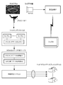
- FIG. 1 is a schematic configuration diagram of a virtual reality providing system according to the first embodiment.
- FIG. 2 is a diagram showing a coordinate system of each parameter of tracking data.
- FIG. 3 is a diagram for explaining the amount of change.
- FIG. 4 is a diagram for explaining the data structure of the tracking data.
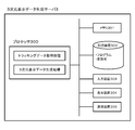
- FIG. 5 is a block diagram of the three-dimensional display data generation server 3 configured by a computer system.
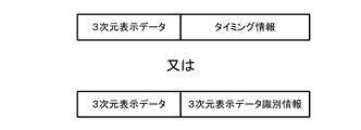
- FIG. 6 is a diagram for explaining the data structure of the three-dimensional display data.
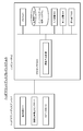
- FIG. 7 is a block diagram of the head mounted display system 5.
- FIG. 8 is a diagram illustrating an example of a three-dimensional image displayed on the display unit 511.
- FIG. 9 is a sequence diagram showing a flow of processing and information from the tracking system 2 to the head mounted display system 55 in the first embodiment.
- FIG. 9 is a sequence diagram showing a flow of processing and information from the tracking system 2 to the head mounted display system 55 in the first embodiment.
- FIG. 9 is a sequence diagram showing a
- FIG. 10 is a schematic configuration diagram of a virtual reality providing system in a modified example of the first embodiment.
- FIG. 11 is a sequence diagram showing a process and information flow from the broadcasting facility 7 to the head mounted display system 5 in the modification of the first embodiment.
- FIG. 12 is a schematic configuration diagram of a virtual reality providing system according to the second embodiment.
- FIG. 13 is a block diagram of the distribution data generation server 10 configured by a computer system.
- FIG. 14 is a block diagram of the head mounted display system 5 in the second embodiment.
- FIG. 15 is a sequence diagram showing a process and information flow from the live video generation unit 9 to the head mounted display system 5 in the second embodiment.
- FIG. 16 is a block diagram of the head mounted display system 5 according to the third embodiment.
- FIG. 17 is a diagram illustrating an example of an image when a virtual ball and a virtual bat collide.
- FIG. 18 is a diagram illustrating an example of a trajectory image of the virtual ball after the collision between the virtual ball and the virtual bat.
- FIG. 19 is a diagram showing an example of a plurality of different virtual examples.
- FIG. 20 is a schematic configuration diagram of a virtual reality providing system according to the fourth embodiment.
- FIG. 21 is a block diagram of the aggregation server 11 configured by a computer system.
- FIG. 22 is an example of a statistical result image when the virtual flying object is a ball and the virtual concrete is a bat.
- FIG. 23 is a diagram illustrating an example of a video in which a live video and a statistical image are combined.
- FIG. 24 is a schematic configuration diagram of a virtual reality providing system according to the fifth embodiment.
- FIG. 1 is a schematic configuration diagram of a virtual reality providing system according to the first embodiment.
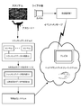
- 1 is a real athlete (actual athlete) playing a game at a stadium, etc.
- 2 is a tracking system
- 3 is a three-dimensional (3D) display data generation server
- 4 is broadcast transmission.
- 5 is a head-mounted display system (virtual space providing system)
- 6 is a camera
- 7 is a broadcasting facility
- 8 is a television.
- a head mounted display system will be described as an example of a virtual space providing system.
- the virtual space providing system is not limited to the head-mounted display system, and may be any system that can present a three-dimensional virtual space to the user.
- the left-eye and right-eye images taken at the same time are displayed on the screen, and the user wears glasses such as a linear polarization filter method or a liquid crystal shutter method to view the virtual space. It may be a system as provided.
- Athlete 1 is an athlete who is playing a game in a situation where it is broadcast live via television broadcast, such as a professional baseball game.
- the baseball game is shot by the camera 6, and the video of the game is broadcast by the broadcasting equipment 7 and viewed by the television 8.
- a baseball game is taken as an example, but not limited to baseball, tennis, table tennis, golf, soccer, martial arts (boxing, fencing), or the like may be used.
- the tracking system 2 is a system that tracks the athlete 1 and the flying object emitted from the athlete 1 and converts it into data.
- the flying object is a typical example of a ball that is thrown or kicked from the athlete 1, but is not limited thereto.
- a part of the body of the athlete 1 for example, a boxing punch
- a tool worn by the athlete 1 for example, a fencing sword
- the tracking system 2 includes a sensor 21 such as a radar and a camera, and a tracking data generation unit 22 that generates tracking data of the athlete 1, the ball, and the referee on the pitch from the data obtained from the sensor 21.
- a tracking system 2 systems such as TrackMan and PITCHf / x are provided.
- tracking data for all moving objects (athlete 1, referee, etc.) on the pitch is not required, and the tracking system 2 tracks at least a flying object (for example, a ball) emitted from the athlete 1. It only needs to be able to generate data.
- the coordinate system of each parameter is based on a predetermined position of the home base, the catcher direction is the front, the catcher direction is the front, the catcher right direction is the X direction (X axis), and the catcher direction is the Y direction.
- (Y axis) is a coordinate system in which the height direction is the Z direction (Z axis).
- the tracking data may be of any type as long as it represents the movement of the athlete 1 or the ball. Moreover, it is preferable that the tracking system 2 includes the acquisition time when the tracking data is acquired in the tracking data as shown in FIG. 4, for example.
- the three-dimensional (3D) display data generation server 3 is a virtual vehicle in which a flying object such as a ball is visualized in a virtual space, and a virtual image in which a real athlete 1 is imaged in a virtual space.
- Three-dimensional display data (three-dimensional coordinate data) for displaying a moving object is generated from tracking data.
- the 3D display data generation server 3 includes a tracking data acquisition unit 31 and a 3D display data generation unit 32.
- the tracking data acquisition unit 31 acquires tracking data provided from the tracking system 2.
- the three-dimensional display data generation unit 32 generates, from the tracking data, three-dimensional display data for displaying a virtual flying object such as a virtual ball and a virtual moving object such as a virtual athlete 1 on the head mounted display system 5. .
- the 3D display data for displaying the virtual moving body of the real athlete 1 is not necessarily required as long as at least 3D display data for displaying the virtual flying object can be generated.
- the three-dimensional display data generation server 3 can be realized by a computer system (information processing apparatus) having a processor that performs various arithmetic processes.
- FIG. 5 is a block diagram of the three-dimensional display data generation server 3 configured by a computer system.
- the three-dimensional display data generation server 3 includes a processor 300, a memory (ROM or RAM) 301, a storage device (hard disk, semiconductor disk, etc.) 302, an input device (keyboard, mouse, touch panel, etc.) 303, a display device 304, and a communication device 305. It can be constituted by a general-purpose computer having hardware resources such as
- the 3D display data generation server 3 implements tracking data acquisition processing and 3D display data generation processing by loading a program stored in the storage device 302 into the memory 301 and executing it by the processor 300. It is.
- the tracking data acquisition process corresponds to the tracking data acquisition unit 31, and the 3D display data generation process corresponds to the 3D display data generation unit 32.
- the tracking data acquisition process is a process for acquiring tracking data provided from the tracking system 2.
- the three-dimensional display data generation processing is a three-dimensional display data for displaying a virtual moving object (virtual athlete in this example) such as a virtual flying object (virtual ball in this example) or a virtual athlete on the head mounted display system 5.
- a virtual moving object virtual athlete in this example
- a virtual flying object virtual ball in this example
- a virtual athlete on the head mounted display system 5 Is generated from the tracking data. More specifically, when the tracking data is data relating to a pitch change, a hitting angle, an athlete on the field, a hitting ball, and a movement of a pitching, the head-mounted display system 5 stores a virtual ball or a virtual athlete. This is a process of converting into the three-dimensional display data necessary for display.
- the three-dimensional display data is a concept including data obtained by converting tracking data into a data format that can be processed by the head mounted display system 5. Therefore, the three-dimensional display data generation process may be a process that simply converts the tracking data into a data format that can be processed by the head mounted display system 5, or a process that generates from tracking data to orbit data such as a virtual flying object. But it ’s okay.
- the head mounted display system 5 is necessary for reproducing and displaying the virtual ball (virtual flying object) corresponding to the actual ball from the tracking data of the actual ball.
- An example of generating the three-dimensional display data will be described.
- the flying image of the virtual ball (virtual flying object) can be reproduced and displayed if the following four elements are determined.
- Release point coordinates Release point coordinates can be obtained from tracking data.
- the release point coordinates are not necessarily exact coordinate values because they match the pitching motion of the pitcher's virtual moving body displayed on the head mounted display system 5.
- Acceleration added to each display frame of the head mounted display system 5 (ball bending force)
- the acceleration can be obtained by dividing the amount of change acquired from the tracking data by the display frame rate of the head mounted display system 5.
- Air resistance to the ball is set so that the final speed (speed indicated with actual landing point coordinates) is 90% -92% with respect to the initial speed.
- the vector in the Y direction from the pitcher to the home base can be obtained from the initial speed acquired from the tracking data.
- vectors in the X direction and the Z direction cannot be acquired from the tracking data.
- the actual landing points are different, it is possible to simulate pitching with exactly the same speed and variation. Accordingly, the ball landing point is brought closer to the original actual landing point while gradually changing the values of the initial velocity vector in the X direction and the Z direction.
- the vectors in the X direction and the Z direction when the ball landing point is closest to the actual landing point are adopted as the X direction and Z direction vectors.
- these four elements are generated as 3D display data.
- the head mounted display system 5 is moved to a virtual ball (in synchronization with a predetermined video section of the video of the athlete 1 game broadcasted by the broadcasting facility 7.
- Timing information related to the timing for displaying the flying image of the virtual flying object is included in the generated three-dimensional display data.
- Timing information may be of any type as long as the time of a predetermined video section is known, but includes time information, a time code of a video of an athlete 1 game, and the like.
- the predetermined video section is, for example, a section in which the commentator announces that a virtual ball (virtual flying object) can experience the flying image, or a virtual ball (virtual flying object) flying image on the broadcast image.
- the video section is a concept including only sound such as radio broadcasting.
- the predetermined video section may be acquired by the 3D display data generation server 3 storing a predetermined video section, or may be received from the broadcast facility 7 as appropriate.
- timing information for example, after a scene (video section) in which A pitcher threw a determined ball, A pitcher throws during a video section displaying a notice that he can experience the determined pitch of A pitcher.
- the flying image of the determined virtual ball can be reproduced by the head mounted display system 5. In this way, cooperation with a television relay or the like can be performed.
- timing information needs to specify tracking data of the flying object actually released by the athlete 1.
- the tracking data can be specified by using the tracking data acquisition time included in the tracking data.
- the 3D display data includes 3D display data identification information that can uniquely identify the 3D display data, and the head mounted display system 5 You may make it transmit to.
- the 3D display data identification information only needs to be able to individually identify each 3D display data, and includes the above-described tracking data acquisition time, an identifier for uniquely identifying the 3D display data, and the like. .
- the flying image of the virtual ball is displayed on the head mounted display system 5.
- Execution information including 3D display data identification information for identifying 3D display data used for executing virtual reality is transmitted from the 3D display data generation server 3 or the broadcast transmission system 4 at the display timing. To do.
- the head mounted display system 5 receives the execution information and displays the flying image of the virtual ball (virtual flying object) using the 3D display data specified by the 3D display data identification information included in the execution information. Display on system 5.
- the 3D display data is transmitted to at least one or more head mounted display systems 5 via the broadcast transmission system 4.
- the 3D display data generation server 3 may acquire not only the 3D display data but also only the audio from the TV video of the game and transmit it together with the 3D display data. At this time, time information is also given to the audio data so that the tracking data acquisition time and the audio data are synchronized. In this way, as will be described later, when the video of the virtual space is displayed in the head mounted display system 5, the live sound actually emitted in the stadium is output, and the virtual space with a more realistic feeling is output. Can be realized.
- the 3D display data generation server 3 may be configured by a single computer or by distributed computing using a plurality of computers. In order to increase the processing speed, part or all of the functions of the three-dimensional display data generation server 3 can be realized by using dedicated hardware (eg, GPU, FPGA, ASIC, etc.).
- dedicated hardware eg, GPU, FPGA, ASIC, etc.
- Broadcast transmission system 4 is a system that broadcasts three-dimensional display data to a plurality of head mounted display systems 5 connected to a network.
- a content delivery network Content (Delivery Network: CDN).
- the broadcast transmission system 4 preferably broadcasts the three-dimensional display data with real-time characteristics synchronized with the video broadcast of the game broadcast described above.
- One of the implementation methods is to refer to the tracking data acquisition time included in the 3D display data and the time code on the TV image side so that the 3D display data can be synchronized with the TV image. Can be sent.
- the head-mounted display (head-mounted display: “Head-Mounted Display”, HMD) system 5 has a display unit capable of displaying a three-dimensional image having a depth for a user who wears the head-mounted display. And it is comprised so that the three-dimensional image
- positioned can be displayed on a display part.
- the display unit is disposed so as to cover both eyes of the user.
- the display unit displays a 3D video to the user by displaying images with parallax on the left and right image display surfaces, respectively. Thereby, a user wearing a head mounted display on the head can experience a sense close to reality as a three-dimensional image in the virtual space.
- FIG. 7 is a block diagram of the head mounted display system 5.
- the head mounted display system 5 includes a head mounted display 51 and a computer 52.
- the head mounted display 51 includes a display unit 511 on which a virtual space image is displayed, a head position detection sensor 512, and a speaker 513.
- the head position detection sensor 512 is configured to detect the position and posture of the user's head in the absolute coordinate system of the user's head and output the detection signal to the computer 52. Since the head position detection sensor 512 is provided integrally with the head mounted display 51, the head mounted display 51 is mounted on the user's head, thereby tracking the movement of the user's head and detecting the position and posture. Can be detected. The detection result is fed back to the three-dimensional video in the virtual space displayed by the display unit 511 of the head mounted display 51, thereby presenting the three-dimensional video viewed from the viewpoint position corresponding to the movement of the user's head. be able to.
- the speaker 513 outputs sound to the user, and for example, outputs sound corresponding to the situation in the virtual space to the user.
- the means for transmitting the voice to the user is not limited to the speaker 513, and may be other voice output means such as an earphone.
- the head mounted display 51 having such a function there are, for example, HTC Vive, Oculus VR Rift of Oculus VR, and the like.
- the head position detection sensor 512 may be provided separately from the head mounted display 51 and mounted on the user's head.
- the computer 52 is for generating a video to be displayed on the display unit 511 of the head mounted display 51, various arithmetic processes, and the like.
- the computer 52 includes hardware resources such as a processor 520, a memory (ROM or RAM) 521, a storage device (hard disk, semiconductor disk, etc.) 522, an input device (keyboard, mouse, touch panel, etc.) 523, a display device 524, and a communication device 525. It can comprise with the general purpose computer which has.
- the storage device 522 stores a processing program for generating a video or the like to be displayed on the display unit 511 of the head mounted display 51 and performing various arithmetic processes. Furthermore, various objects for generating by the processor 520 a virtual athlete (virtual moving object) in the virtual space of the athlete 1, a virtual ball (virtual flying object) emitted from the virtual athlete, a virtual home base as a background, and the like. Data is stored.
- the program stored in the storage device 522, the object data, and the received three-dimensional display data are loaded into the memory 521, and the processor 520 displays a virtual space image displayed on the display unit 511 of the head mounted display 51 based on the program. Etc. are generated.
- the processor 520 performs image generation processing based on the program.
- the image generation processing includes three-dimensional display data of a virtual ball (virtual flying object) emitted from a virtual athlete (virtual moving object) and a user's head detected by the head position detection sensor 512 by a known computer graphics technique. Using the position and posture of the robot and various object data such as a virtual athlete (virtual moving object) and a virtual ball (virtual flying object), a 3D image of the movement of the virtual athlete and the flying image of the virtual ball is generated in sequence. Are displayed on the display unit 511.
- the image generation process specifies the displayable period by the time information and the time code of the video included in the timing information, and only during that period, A three-dimensional image such as a flying image of a virtual ball is displayed.
- FIG. 8 is a diagram illustrating an example of a three-dimensional image displayed on the display unit 511.
- a virtual pitcher, a virtual ball flying video, a virtual stadium, and the like viewed from a viewpoint position in the virtual space corresponding to the position and orientation of the user are displayed.
- the 3D display data includes 3D display data identification information
- the 3D image such as the flying image of the virtual ball
- the distributed execution information in response to the reception of the execution information, Using the 3D display data specified by the 3D display data identification information included in the execution information, a process of displaying a 3D image such as a flying image of the virtual ball is started.
- the head-mounted display includes a virtual-reality (VR) type head-mounted display in which only a virtual space created by computer graphics or the like is displayed, and a real space (for example, an optically transmitted real space). ) And a virtual space are displayed in real time, there is a Mixed Reality (MR) type head mounted display, but the present invention can be applied to any head mounted display.
- VR virtual-reality
- MR Mixed Reality
- An example of the MR type head mounted display is Microsoft's HoloLens.
- the head mounted display system 5 described above, an example in which the head mounted display 51 and the computer 52 are physically configured as separate housings has been described, but the present invention is not limited thereto.
- the head mounted display system 5 may be configured by integrating the head mounted display 51 and the computer 52.
- An example of the head mounted display system 5 in which the head mounted display 51 and the computer 52 are integrated is the above-mentioned HoloLens of Microsoft Corporation.
- the head mounted display system 5 may not be a dedicated head mounted display system.
- a smartphone is attached to a goggle-type headset, the same function as a head-mounted display can be realized.
- An example of this is Samsung's Galaxy Gear VR.
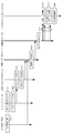
- FIG. 9 is a sequence diagram showing a flow of processing and information from the tracking system 2 to the head mounted display system 5 in the first embodiment.
- the tracking system 2 senses the ball thrown from the athlete 1 (pitcher) on the pitch of the game being relayed in real time with a radar, a camera or the like.
- the athlete 1, the referee, and the like on the pitch may be sensed in real time by a radar, a camera, or the like (Step 1).
- At least tracking data of the ball thrown from the athlete 1 (pitcher) is generated from the sensed data. It is also possible to generate tracking data such as athlete 1 on the pitch, referee, etc. (Step 2).
- time information of tracking data is also acquired.
- the tracking data including time information is transmitted to the three-dimensional display data generation server 3.
- the 3D display data generation server 3 acquires tracking data (Step 3).
- the three-dimensional display data generation server 3 generates three-dimensional display data for displaying the flying image of the virtual ball on the head mounted display system 5 based on the acquired tracking data.
- Three-dimensional display data for displaying a virtual athlete may also be generated (Step 4).
- the timing information for displaying the flying image of the virtual ball is included in the three-dimensional display data using the tracking data acquisition time.
- the tracking data acquisition time may be included in the generated three-dimensional display data. Then, the three-dimensional display data is transmitted to the broadcast transmission system 4.
- Broadcast transmission system 4 broadcasts the received three-dimensional display data to a plurality of head mounted display systems 5 connected to the network (Step 5).
- the broadcast transmission of the 3D display data is performed in the order from the time code information of the video relayed on the television when the tracking data acquisition time is included in the 3D display data. By doing so, it is possible to broadcast the 3D display data in a form following the TV broadcast of the game, and to maintain the real-time property to some extent.
- the head mounted display system 5 receives the 3D display data (Step 6).
- the head mounted display system 5 specifies the displayable period based on the time information included in the timing information and the time code of the video, and is mounted during that period.
- a three-dimensional image (flying image) of the virtual ball viewed from the viewpoint position corresponding to the movement of the user's head is displayed (Step 7).
- the head mounted display system 5 is mounted at the timing when the execution information including the 3D display data identification information is received.
- a three-dimensional image (flying image) of the virtual ball viewed from the viewpoint position corresponding to the movement of the user's head is displayed (Step 7).
- the virtual pitcher (virtual athlete) who throws the virtual ball may be displayed using the object data of the virtual pitcher stored in advance in the head mounted display system 5, or the actual pitcher is displayed on the three-dimensional display data. If display data is stored, it may be used to display a virtual pitcher.
- information on movements of athletes, balls, and the like is broadcast to the head mounted display system while maintaining a certain degree of synchronism with the video of a game such as a delivered sport.
- the user can not only watch the athlete's performance from the video but also experience the athlete's performance from the user's free viewpoint by using the head mounted display system.
- FIG. 10 is a schematic configuration diagram of a virtual reality providing system in a modified example of the first embodiment.
- the head mounted display system 5 and the television 8 are compatible with the hybrid cast standard
- the head mounted display system 5 is connected to the television 8 with the hybrid cast standard.
- the broadcast transmission system 4 functions as a hybrid cast server.
- the broadcast transmission system 4 adds the three-dimensional display data to the three-dimensional display data such as a virtual flying object (virtual ball) acquired from the three-dimensional display data generation server 3.
- the three-dimensional display data identification information that can be uniquely identified is transmitted to the head mounted display system 5.
- the 3D display data identification information may be any information as long as each 3D display data can be individually identified, and includes the tracking data acquisition time and the identifier for individually identifying the 3D display data.
- the broadcasting facility 7 broadcasts an event message storing 3D display data identification information for identifying 3D display data used when executing virtual reality at the timing of executing virtual reality in the head mounted display system 5.
- the 3D display data identification information is, for example, an identifier for individually identifying the tracking data acquisition time and the 3D display data described above.
- the television 8 detects and analyzes the event message broadcast from the broadcasting facility 7 and transmits the 3D display data identification information stored in the event message to the head mounted display system 5.
- the image generation processing unit 520 of the head mounted display system 5 uses the three-dimensional display data having the three-dimensional display data identification information transmitted from the television 8 among the received three-dimensional display data. As in the embodiment, a three-dimensional image of the virtual athlete's motion and the flying image of the virtual ball is sequentially generated and displayed on the display unit 511.
- FIG. 11 is a sequence diagram showing a process and information flow from the broadcasting facility 7 to the head mounted display system 5 in the modification of the first embodiment.
- the broadcasting facility 7 broadcasts a live video of the game being relayed (Step 1).
- the television 8 receives the broadcast wave and displays a live video (Step 2).
- the tracking system 2 senses the ball thrown from the athlete 1 (pitcher) on the pitch of the game being relayed in real time with a radar, a camera or the like.
- the athlete 1, the referee, and the like on the pitch may be sensed in real time by a radar, a camera, or the like (Step 3).
- At least tracking data of the ball thrown from the athlete 1 (pitcher) is generated from the sensed data. It is also possible to generate tracking data such as athlete 1 on the pitch, referee, etc. (Step 4). Then, the tracking data is transmitted to the three-dimensional display data generation server 3.
- the 3D display data generation server 3 acquires tracking data (Step 5).
- the three-dimensional display data generation server 3 generates three-dimensional display data for displaying the flying image of the virtual ball on the head mounted display system 5 based on the acquired tracking data (Step 6).
- three-dimensional display data for displaying a virtual athlete may also be generated (Step 4).
- a three-dimensional display data identifier for identifying the three-dimensional display data is included in the generated three-dimensional display data.
- the three-dimensional display data is transmitted to the broadcast transmission system 4.
- the three-dimensional display data identifier used here is a three-dimensional display data identifier shared with the broadcasting facility 7 in advance.
- the broadcast transmission system 4 transmits the received three-dimensional display data to the head mounted display system 5 using hybrid cast (Step 7).
- the head mounted display system 5 receives the three-dimensional display data (Step 8).
- the broadcasting facility 7 broadcasts an event message in which a three-dimensional display data identifier is stored at the timing of executing virtual reality in the head mounted display system 5 (Step 9).
- the television 8 detects an event message broadcast from the broadcasting facility 7, analyzes the event message, and transmits a three-dimensional display data identifier to the head mounted display system 5 (Step 10).
- the head mounted display system 5 collates the three-dimensional display data identifier received from the television 8 with the three-dimensional display data identifier of the received three-dimensional display data (Step 11). Then, using the three-dimensional display data having the three-dimensional display data identifier received from the television 8, a three-dimensional image (flight image) of the virtual ball viewed from the viewpoint position corresponding to the movement of the head of the wearing user. Is displayed (Step 12). At this time, the virtual pitcher or virtual pitcher (virtual athlete) may display the virtual pitcher object data stored in the head-mounted display system 5 in advance, or may display the actual pitcher as three-dimensional display data. If the display data is stored, the virtual pitcher may be displayed using the display data.
- the broadcast station side generates 3D display data of tracking data for a predetermined player and part of the game time, generates 3D display data for the player and time, and broadcasts it. May broadcast an event message including the corresponding three-dimensional display data identification information.
- the broadcast station side can designate the timing for executing virtual reality on the head mounted display system 5 as a program-linked service, and the program video of a game such as sports to be broadcast and The interlocked virtual reality can be provided by the head mounted display system 5.
- FIG. 12 is a schematic configuration diagram of a virtual reality providing system according to the second embodiment.
- the video of the baseball game shot by the camera 6 is not transmitted to the television broadcast but to a terminal such as a tablet or a smartphone by a content delivery network system. Broadcast transmission.
- the second embodiment is different from the first embodiment in that the three-dimensional display data is transmitted together with the transmitted game video data.
- a live video generation unit 9 that generates video data of a live video of a game
- a distribution data generation server that generates distribution data by including 3D display data in the video data of a live video of a game 10 are provided.
- symbol is attached
- the distribution data generation server 10 can be realized by a computer system having a processor that performs various arithmetic processes.
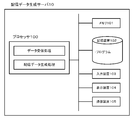
- FIG. 13 is a block diagram of the distribution data generation server 10 configured by a computer system.
- the distribution data generation server 10 includes a processor 100, a memory (ROM or RAM) 101, a storage device (hard disk, semiconductor disk, etc.) 102, an input device (keyboard, mouse, touch panel, etc.) 103, a display device 104, a communication device 105, and the like.
- a processor 100 a memory (ROM or RAM) 101, a storage device (hard disk, semiconductor disk, etc.) 102, an input device (keyboard, mouse, touch panel, etc.) 103, a display device 104, a communication device 105, and the like.
- ROM or RAM read-only memory
- storage device hard disk, semiconductor disk, etc.
- an input device keyboard, mouse, touch panel, etc.
- display device 104 a display device 104
- a communication device 105 and the like.
- a general-purpose computer having hardware resources can be used.
- the distribution data generation server 10 implements distribution data generation processing by loading a program stored in the storage device 102 into the memory 101 and executing it by the processor 100.
- the processor 100 performs reception processing for receiving live video data and 3D display data, and distribution data generation processing for generating distribution data.
- the distribution data generation process generates distribution data in a format in which live video data and 3D display data can be separated on the head mounted display system 5 side. For example, an identifier that identifies video data is assigned to the header of a packet of video data, and an identifier that identifies that it is 3D display data is appended to the header of a packet of 3D display data. Generate data. On the head mounted display system 5 side, the video data and the three-dimensional display data can be separated by the identifier. Further, when there is a field that can include data other than video data in the payload of each packet of video data, the field may be inserted in a format that can identify 3D display data.
- the distribution data generation process refers to the time code of the video data and the acquisition time of the tracking data included in the 3D display data, and generates the distribution data so that the data are synchronized with each other. For example, if there is a field that can include data other than video data in the payload of each packet of video data, 3D display data having the same tracking data acquisition time as the time code of the packet is displayed. Insert into the field. This example is merely an example, and other methods may be used.
- the distribution data generation server 10 transmits the generated distribution data to the broadcast transmission system 4.
- Broadcast transmission system 4 broadcasts to head mounted display system 5 and tablets and smartphones for viewing images.
- FIG. 14 is a block diagram of the head mounted display system 5 in the second embodiment.
- the processor 520 performs a data separation process for separating the video data and the three-dimensional display data by a predetermined separation method. Specifically, when an identifier for identifying the type of each data is assigned to the packet, the video data and the three-dimensional display data are separated based on the identifier. When the payload of each packet of video data includes 3D display data together with the identifier, the video data and 3D display data are separated based on the identifier.
- the image generation process displays a three-dimensional image of the virtual space on the display unit, as in the first embodiment.
- the head mounted display system 5 is a system that can also view distributed video data, either a live video or a three-dimensional video in a virtual space may be selected by the user.
- FIG. 15 is a sequence diagram illustrating a process and information flow from the live video generation unit 9 to the head mounted display system 5 according to the second embodiment.
- the same step number was given about the operation
- the live video generation unit 9 generates video data of the game being relayed (Step 1).
- the generated video data is transmitted to the distribution data generation server 10.
- the ball thrown from the athlete 1 (pitcher) on the pitch of the game being relayed is sensed in real time by a radar, a camera or the like.
- the athlete 1, the referee, and the like on the pitch may be sensed in real time by a radar, a camera, or the like (Step 1).
- At least tracking data of the ball thrown from the athlete 1 (pitcher) is generated from the sensed data. It is also possible to generate tracking data such as athlete 1 on the pitch, referee, etc. (Step 2).
- time information of tracking data is also acquired.
- the tracking data including time information is transmitted to the three-dimensional display data generation server 3.
- the 3D display data generation server 3 acquires tracking data (Step 3).
- the three-dimensional display data generation server 3 generates three-dimensional display data for displaying a flying image of the virtual ball on the head mounted display system 5 based on the acquired tracking data (Step 4). Note that three-dimensional display data for displaying the virtual athlete may also be generated. At this time, the tracking data acquisition time is included in the generated three-dimensional display data. Then, the three-dimensional display data is transmitted to the distribution data generation server 10.
- the distribution data generation server 10 generates the distribution data by including the 3D display data in the video data of the live video of the game (Step 11).
- the generated distribution data is transmitted to the broadcast transmission system 4.
- Broadcast transmission system 4 broadcasts the received distribution data to a plurality of head mounted display systems 5, tablets and smartphones (not shown) connected to the network (Step 5).
- the head mounted display system 5 receives the distribution data (Step 6).
- the head mounted display system 5 performs a data separation process for separating the video data and the three-dimensional display data by a predetermined separation method (Step 12).
- the head mounted display system 5 displays a three-dimensional image (flying image) of the virtual ball viewed from the viewpoint position corresponding to the movement of the head of the user who is wearing (Step 7).
- the virtual pitcher or virtual pitcher may display the virtual pitcher object data stored in the head-mounted display system 5 in advance, or may display the actual pitcher as three-dimensional display data. If the display data is stored, the virtual pitcher may be displayed using the display data.
- the second embodiment can synchronize the distribution of 3D display data and the distribution of live video on the data distribution side. As a result, the user can experience the athlete's performance at a more synchronized timing with the current game.
- the second embodiment can also include timing information in the three-dimensional display data.
- the tracking data acquisition time may not be included in the three-dimensional display data, but only the timing information may be included.
- the distribution data generation server 10 sends the 3D display data and the video data to the head mounted display before the timing (predetermined video section) for displaying the 3D video (flight video) specified by the timing information.
- Distribution data is generated in a format that can be separated on the system 5 side.
- the second embodiment can obtain the same effects as those of the first embodiment.
- the 3D display data may be transmitted to the head mounted display system 5 by including 3D display data identification information that can uniquely identify the 3D display data.
- the flying image of the virtual ball is displayed on the head mounted display system 5.
- the distribution data generation server 10 transmits execution information including 3D display data identification information for identifying 3D display data used when executing virtual reality.
- the head mounted display system 5 receives the execution information and displays the flying image of the virtual ball (virtual flying object) using the 3D display data specified by the 3D display data identification information included in the execution information. Display on system 5.
- the second embodiment can obtain the same effects as those of the first embodiment.
- the third embodiment is in addition to the first embodiment (including modifications of the first embodiment) or the second embodiment (including modifications of the second embodiment).
- FIG. 16 is a block diagram of the head mounted display system 5 in the third embodiment.
- the tool tracking acquisition unit 520 for tracking the movement of the tool used by the user in a state where the user wears the head mounted display 51 is provided.
- the tool tracking acquisition unit 520 can use Microsoft's Kinect (registered trademark), ASUS Xtion Pro (registered trademark), or the like. It is also possible to provide an acceleration sensor in the tool and acquire the tracking data of the tool.
- the processor 520 of the computer 52 performs the tool 3D display data generation process.
- the tool 3D display data generation process calculates virtual specific 3D display data (trajectory data) corresponding to the tool based on the tool tracking data acquired by the tool tracking acquisition unit 520. In addition, based on the three-dimensional display data (orbit data) of the virtual flying object and the three-dimensional display data (orbit data) for the virtual object, a new one resulting from the collision between the virtual object and the virtual object in the virtual space. 3D display data (orbit data) of a virtual flying object is calculated.
- the tool 3D display data generation process is such that when the virtual flying object is a virtual ball and the virtual object is a virtual bat, the user swings the bat according to the flying image of the virtual ball thrown from the virtual athlete. Then, three-dimensional display data (orbit data) of the swing of the virtual bat is calculated from the tracking data of the bat. Then, the tool 3D display data generation process is performed by using the virtual bat and the virtual ball in the virtual space based on the virtual bat 3D display data (orbit data) and the virtual ball 3D display data (orbit data). Determine whether to collide (determine whether the virtual ball hits the virtual bat).
- three-dimensional display data (orbit data) of the flight trajectory of the virtual ball after the collision is generated based on the size of the virtual bat and the coefficient of restitution.
- the image generation process generates and displays a flying image of the virtual ball after the collision based on the three-dimensional display data (orbit data) of the flying trajectory of the virtual ball.
- FIG. 17 is an example of an image when the virtual ball and the virtual bat collide
- FIG. 18 is an example of a flying image of the virtual ball after the collision between the virtual ball and the virtual bat.
- a plurality of virtual tool sizes and restitution coefficients corresponding to tools used by the user may be prepared so that the user can select them.
- the tool is a bat, as shown in FIG. 19, a plurality of virtual bats having different sizes and different restitution coefficients may be prepared and selected by the user.
- the user sees the performance of the athlete, but also the user can hit or catch a virtual flying object similar to a ball or the like emitted by the real athlete. Can challenge.
- a collision result indicating whether a virtual flying object and a virtual concrete in each head mounted display system 5 collide, and a new trajectory of the virtual flying object. This is a mode in which the flight results of the virtual flying object obtained from the data are totaled and the totaled results are reflected in the live video.
- FIG. 20 is a schematic configuration diagram of a virtual reality providing system according to the fourth embodiment.
- the computer 52 of the head mounted display system 5 determines whether or not the virtual flying object collides with the virtual concrete. For example, it is determined whether or not the virtual ball and the virtual bat collide, that is, the virtual ball can be hit.
- the flight result of the virtual flying object is calculated. For example, whether a hit ball hit a virtual ball is a hit or a home run. Then, the collision result and the flight result are transmitted to the aggregation server 11. Furthermore, the collision result and flight result of each user are managed individually.
- the aggregation server 11 can be specifically realized by a computer system having a processor that performs various arithmetic processes.
- FIG. 21 is a block diagram of the aggregation server 11 configured by a computer system.
- the aggregation server 11 includes hardware such as a processor 110, a memory (ROM or RAM) 111, a storage device (hard disk, semiconductor disk, etc.) 112, an input device (keyboard, mouse, touch panel, etc.) 113, a display device 114, and a communication device 115.
- a processor 110 a memory (ROM or RAM) 111
- a storage device hard disk, semiconductor disk, etc.
- an input device keyboard, mouse, touch panel, etc.
- display device 114 a display device 114
- a communication device 115 a general-purpose computer having resources can be used.
- the aggregation server 11 performs the aggregation process by loading the program stored in the storage device 112 into the memory 111 and executing it by the processor 110.
- the tabulation process tabulates the collision result and the flight result transmitted from each head mounted display system 5. For example, the number of head mounted display systems 5 that transmitted the collision result and the flight result, the ratio of the collision result (collision) to the number of the head mounted display system 5, or the ratio of the flight result.
- the aggregation server 11 performs an aggregation result image generation process for generating an aggregation result image that is an image of the aggregation result.
- FIG. 22 is an example of an image of a statistical result when the virtual flying object is a ball and the virtual concrete is a bat.
- the aggregation server 11 transmits the generated statistical image to a broadcasting facility or a broadcast transmission system.
- FIG. 23 is a diagram illustrating an example of a video in which a live video and a statistical image are combined.
- the fourth embodiment is applicable not only when broadcasting live video, but also when transmitting live video using a content delivery network system.
- the performance of the user wearing the head mounted display is reflected in the live video, it is possible not only to simply watch the live broadcast but also to provide a new experience in which the user can become the main player.
- the fifth embodiment is in addition to the first embodiment (including modifications of the first embodiment) or the second embodiment (including modifications of the second embodiment).
- the server 1 has a prediction server 12 that predicts the ball type of the ball that the athlete 1 such as a pitcher will throw next to the batter from past results.
- FIG. 24 is a schematic configuration diagram of a virtual reality providing system according to the fifth embodiment.
- the prediction server 12 includes a tracking data acquisition unit 121 and a prediction unit 122.
- the tracking data acquisition unit 121 acquires tracking data provided from the tracking system 2.
- the acquired tracking data includes data for identifying the pitcher and the batter who is fighting.
- the prediction unit 122 machine-learns the ball type that each pitcher has thrown against each batter in the past and inputs the acquired tracking data, and then predicts the ball type that the pitcher will throw next to the batter.
- the predicted sphere type is transmitted to the three-dimensional display data generation server 3 in the same format as the tracking data.
- the 3D display data generation server 3 acquires tracking data from the prediction server 12.
- the three-dimensional display data generation unit 32 generates three-dimensional display data for displaying a flying image of the predicted virtual ball type on the head mounted display system 5 as in the above-described embodiment. Then, the generated three-dimensional display data is transmitted to at least one or more head mounted display systems 5 via the broadcast transmission system 4.
- the fifth embodiment is the same as that of the first embodiment described above (including modifications of the first embodiment) or the second embodiment (including modifications of the second embodiment).
- the user can experience the ball of the ball type that the pitcher is expected to throw next.
- the fifth embodiment can be configured not only in the first embodiment described above (including modifications of the first embodiment) but also in combination with the second to fourth embodiments. it can.
- At least one virtual space providing system for providing a user with a three-dimensional image of the virtual space; tracking data acquisition means for acquiring tracking data of a flying object emitted from a real athlete at least on the pitch, acquired from a sensor; Three-dimensional coordinate data generating means for generating three-dimensional coordinate data for displaying a virtual flying object corresponding to the flying object in a virtual space displayed on the virtual space providing system based on the acquired tracking data;
- a virtual reality providing system comprising: a transmitting unit that transmits the three-dimensional coordinate data to the at least one virtual space providing system via a broadcast transmitting unit.
- the tracking data includes tracking data of a real athlete's movement on the pitch
- the three-dimensional coordinate data generating means generates three-dimensional coordinate data for displaying a virtual operating body corresponding to the real athlete in a virtual space displayed on the virtual space providing system based on the acquired tracking data.
- the virtual reality providing system according to attachment 1.
- Distribution data generation means for generating distribution data including video data of the athlete's actual video and the three-dimensional coordinate data;
- the transmission means transmits the distribution data to the at least one virtual space providing system via the broadcast transmission means,
- the virtual space providing system according to Supplementary Note 1 or Supplementary Note 2, wherein the virtual space providing system includes a separating unit that separates the video data and the three-dimensional coordinate data from the distribution data.
- the virtual space providing system includes: Storage means for storing object data of the virtual flying object and the virtual moving object, and virtual specific object data corresponding to the tool handled by the user; Receiving means for receiving the three-dimensional coordinate data; Position / orientation detection means for detecting the user position data and the user orientation data in the virtual space; Tool tracking data acquisition means for acquiring tracking data of the tool handled by the user; First calculation means for calculating three-dimensional coordinate data for displaying virtual details corresponding to the tool in a virtual space displayed on the virtual space providing system based on the tracking data of the tool; Based on the three-dimensional coordinate data of the virtual flying object and the three-dimensional coordinate data for the virtual, the flight of the virtual flying object caused by the collision between the virtual flying object and the virtual concrete in the virtual space A second computing means for calculating the three-dimensional coordinate data of the trajectory; Based on the three-dimensional coordinate data, the object data, and the position data and orientation data of the user, the virtual flying object from the viewpoint position in the virtual space corresponding to the position and orientation of the user, the
- the storage means includes flying object data relating to at least the size of a plurality of virtual flying objects, flying object restitution coefficient data of restitution coefficients of the plurality of virtual flying objects for the virtual tool, and tools relating to at least the size of the plurality of virtual tools.
- Data and tool restitution coefficient data of restitution coefficient for the virtual flying object of the plurality of virtual tools are stored;
- the second calculation means refers to the flying object data, the flying object restitution coefficient data, the tool data, and the restitution coefficient data, and the new calculation means resulting from a collision between the virtual flying object and the virtual object.
- the virtual reality providing system according to appendix 5, which calculates the trajectory data of the virtual flying object.
- the virtual space providing system includes: Third calculation means for calculating a collision result of whether the virtual flying object collides with the virtual concrete and a flying result of the virtual flying object obtained from three-dimensional coordinate data of a flying trajectory of the virtual flying object When, Transmission means for transmitting the collision result and the flight result to the aggregation server;
- the aggregation server is The virtual space providing system totalizes the collision result and the flight result transmitted from to calculate a total result, and displays the total result on a broadcast video or a broadcast transmission video that is a real video of the real athlete.
- the virtual reality providing system according to supplementary note 5 or supplementary note 6, comprising means for transmitting to the knitting apparatus.
- the virtual space providing system is a head mounted display system that is mounted on a user's head and includes a display unit that displays a 3D video of the virtual space, and a 3D video generation unit that generates the 3D video of the virtual space.
- the virtual reality providing system according to any one of appendix 1 to appendix 7, wherein
- a computer program of a virtual space providing system for providing a user with a 3D image of a virtual space, Three-dimensional coordinate data for displaying a virtual flying object corresponding to the flying object in a virtual space generated from the tracking data of the flying object emitted from at least a pitched real athlete obtained from the sensor is broadcast. Processing received from the transmission means; A process of detecting the user position data and the user orientation data in the virtual space; Based on the three-dimensional coordinate data of the virtual flying object, the object data of the virtual flying object, and the position data and orientation data of the user, the virtual flying from the viewpoint position in the virtual space corresponding to the position and orientation of the user.
- the program is Processing for obtaining tracking data of the tool handled by the user; Based on the tracking data of the tool, a process of calculating specific virtual three-dimensional coordinate data corresponding to the tool; Based on the three-dimensional coordinate data of the virtual flying object and the three-dimensional coordinate data for the virtual, the flight of the virtual flying object caused by the collision between the virtual flying object and the virtual concrete in the virtual space Processing to calculate the three-dimensional coordinate data of the trajectory; Based on the three-dimensional coordinate data, the object data, and the user position data and orientation data, the virtual flying object and the virtual specific trajectory from the viewpoint position in the virtual space corresponding to the position and orientation of the user Processing for generating video and displaying it on the display means of the virtual space providing system; The viewpoint in the virtual space corresponding to the position and orientation of the user based on the three-dimensional coordinate data of the flight trajectory of the virtual flying object resulting from the collision between the virtual flying object and the virtual concrete in the virtual space
- the program according to appendix 8 further comprising: processing for generating a trajectory image of the
- the program is A process of calculating a collision result of whether the virtual flying object and the virtual concrete collide, and a flying result of the virtual flying object obtained from three-dimensional coordinate data of a flying trajectory of the virtual flying object;
- the virtual space providing system is a head mounted display system that is mounted on a user's head and includes a display unit that displays a 3D video of the virtual space, and a 3D video generation unit that generates the 3D video of the virtual space.
- the program according to any one of appendix 9 to appendix 11, wherein
- Athlete (actual athlete) 2 Tracking system 3 Three-dimensional (3D) display data generation server 4 Broadcast transmission system 5 Head mounted display system 6 Camera 7 Broadcasting equipment 8 Television 9 Live video generation unit 10 Distribution data generation server 11 Aggregation server 12 Prediction server
Abstract
アスリートから放たれた飛体をトラッキングするセンサのセンサ情報から得られた飛体のトラッキングデータを取得するトラッキングデータ取得部と、取得したトラッキングデータを用いて、仮想空間に飛体に対応する仮想飛体の飛翔映像を表示するための3次元表示データを生成する3次元表示データ生成部と、3次元表示データを用いて、仮想空間に仮想飛体の飛翔映像を表示する少なくとも一以上の仮想空間提供システムと、3次元表示データを、少なくとも1以上の仮想空間提供システムに送信する送信部とを有する仮想現実提供システムである。
Description
本発明は仮想現実提供システム、3次元表示データ提供装置、仮想空間提供システム及びプログラムに関する。
ユーザの頭部に装着され、眼前に配置されたディスプレイ等によってユーザに3次元仮想空間画像を提示可能なヘッドマウントディスプレイ(HMD)が知られている。このヘッドマウントディスプレイを利用した練習支援システムが、特許文献1に記載されている。
特許文献1の練習支援システムは、練習者の頭部に装着され、練習者が扱う用具の仮想オブジェクトである仮想動作体を配置した仮想空間の3次元映像を提示する表示手段を有するHMDと、練習者の頭部の位置姿勢を検出する頭部位置検出手段と、用具に取り付けられる角速度検出手段と、角速度検出手段によって取得された角速度データに基づいて仮想動作体の軌道データを算出する演算手段と、軌道データを記憶する記憶手段と、軌道データに基づいて仮想空間内での仮想動作体の軌道映像を生成し、頭部位置検出手段によって検出された練習者の頭部の位置姿勢に対応する仮想空間内の視点位置からの軌道映像を表示手段に提示させる画像生成手段とを備える。
国内のプロ野球中継やJリーグ中継をはじめ、世界的なオリンピックやワールドカップ等、世界中の人々が家にいながらして、テレビやネットを通じたスポーツのライブ観戦を楽しんでいる。
しかし、ライブの映像は観戦のためのものであり、その映像に登場するアスリートのパフォーマンスを体感できるものではない。
そこで、本発明は、映像からアスリートのパフォーマンスを観戦するだけでなく、そのアスリートのパフォーマンスを自ら体験することができる仮想現実提供システム、3次元表示データ提供装置、仮想空間提供システム及びプログラムを提供することにある。
本発明の一態様は、アスリートから放たれた飛体をトラッキングするセンサのセンサ情報から得られた前記飛体のトラッキングデータを取得するトラッキングデータ取得部と、取得したトラッキングデータを用いて、仮想空間に前記飛体に対応する仮想飛体の飛翔映像を表示するための3次元表示データを生成する3次元表示データ生成部と、前記3次元表示データを用いて、仮想空間に仮想飛体の飛翔映像を表示する少なくとも一以上の仮想空間提供システムと、前記3次元表示データを、前記少なくとも1以上の仮想空間提供システムに送信する送信部とを有する仮想現実提供システムである。
本発明の一態様は、アスリートから放たれた飛体をトラッキングするセンサのセンサ情報から得られた前記飛体のトラッキングデータを取得するトラッキングデータ取得部と、取得したトラッキングデータを用いて、仮想空間提供システムに表示される仮想空間に前記飛体に対応する仮想飛体の飛翔映像を表示するための3次元表示データを生成する3次元表示データ生成部と、前記3次元表示データを、前記少なくとも1以上の仮想空間提供システムに送信する送信部とを有する3次元表示データ提供装置である。
本発明の一態様は、仮想空間を表示する表示部と、アスリートから放たれる飛体をトラッキングするセンサのセンサ情報から得られたトラッキングデータから生成され、前記仮想空間に前記飛体に対応する仮想飛体の飛翔映像を表示するための3次元表示データを受信する受信部と、前記仮想空間におけるユーザの位置及び前記ユーザの向きを検出する処理と、前記仮想飛体の3次元表示データ、前記仮想飛体のオブジェクトデータ及び前記ユーザの位置及び向きを用いて、前記ユーザの位置姿勢に対応する前記仮想空間内の視点位置からの前記仮想飛体の飛翔映像を、前記表示部に表示する画像処理部とを有する仮想空間提供システムである。
本発明の一態様は、アスリートから放たれた飛体をトラッキングするセンサのセンサ情報から得られた前記飛体のトラッキングデータを取得するトラッキングデータ取得処理と、取得したトラッキングデータを用いて、仮想空間提供システムに表示される仮想空間に前記飛体に対応する仮想飛体の飛翔映像を表示するための3次元表示データを生成する3次元表示データ生成処理と、前記3次元表示データを、前記少なくとも1以上の仮想空間提供システムに送信する送信処理とをコンピュータに実行させるプログラムである。
本発明の一態様は、ユーザに仮想空間の3次元映像を提供する仮想空間提供システムのコンピュータのプログラムであって、アスリートから放たれる飛体をトラッキングするセンサのセンサ情報から得られたトラッキングデータから生成され、前記仮想空間に前記飛体に対応する仮想飛体の飛翔映像を表示するための3次元表示データを受信する受信処理と、前記仮想空間におけるユーザの位置データ及び前記ユーザの向きデータを検出する検出処理と、前記仮想飛体の3次元表示データ、前記仮想飛体のオブジェクトデータ及び前記ユーザの位置データ及び向きデータを用いて、前記ユーザの位置姿勢に対応する前記仮想空間内の視点位置からの前記仮想飛体の飛翔映像を、表示部に表示する画像処理とをコンピュータに実行させるプログラムである。
本発明によれば、映像からアスリートのパフォーマンスを観戦するだけでなく、そのアスリートのパフォーマンスを自ら体験することができる。
(第1の実施の形態)
第1の実施の形態における仮想現実提供システムを、図面を参照しつつ説明する。図1は、第1の実施の形態における仮想現実提供システムの概略構成図である。
第1の実施の形態における仮想現実提供システムを、図面を参照しつつ説明する。図1は、第1の実施の形態における仮想現実提供システムの概略構成図である。
図1中、1はスタジアム等で試合を行っている現実のアスリート(実アスリート)であり、2はトラッキングシステムであり、3は3次元(3D)表示データ生成サーバであり、4は同報送信システムであり、5はヘッドマウントディスプレイシステム(仮想空間提供システム)であり、6はカメラであり、7は放送設備であり、8はテレビである。
尚、以下の実施の形態の説明では、仮想空間提供システムの例として、ヘッドマウントディスプレイシステムを例にして説明する。しかし、仮想空間提供システムは、ヘッドマウントディスプレイシステムに限られず、ユーザに3次元仮想空間を提示できるものであれば良い。例えば、左眼用と右眼用の映像を同時に撮影したものなどをスクリーンに表示し、ユーザが直線偏光フィルター方式や液晶シャッター方式等の眼鏡を装着して視聴することにより、仮想空間をユーザに提供するようなシステムであっても良い。
アスリート1は、プロ野球の試合のように、テレビ放送などによりライブ中継される状況下で、試合を行っているアスリートである。野球の試合は、カメラ6により撮影され、その試合の映像は放送設備7により放送され、テレビ8により視聴される。尚、本実施の形態では、野球の試合を例にするが、野球に限らず、テニス、卓球、ゴルフ、サッカー、格闘技(ボクシング、フェンシング)等でも良い。
トラッキングシステム2は、アスリート1や、アスリート1から放たれる飛体を追尾してデータ化するシステムである。ここで、飛体とは、アスリート1から投げられたり、蹴られたりして飛球するボールが代表的な例であるが、これに限られない。アスリート1の体の一部(例えば、ボクシングのパンチ)や、アスリート1が身に着けている用具(例えば、フェンシングの剣)でも良い。
トラッキングシステム2は、レーダ、カメラ等のセンサ21と、センサ21から得られたデータから、ピッチ上のアスリート1、ボール、審判のトラッキングデータを生成するトラッキングデータ生成部22とを備える。このような、トラッキングシステム2の代表的な例として、TrackManや、PITCHf/x等のシステムが提供されている。尚、本実施の形態では、ピッチ上の全ての動体(アスリート1、審判等)のトラッキングデータは必要なく、トラッキングシステム2は、少なくもアスリート1から放たれる飛体(例えば、ボール)のトラッキングデータが生成できれば良い。
投手が投げるボールをトラッキングする場合、本実施の形態におけるトラッキングデータ生成部22が生成するトラッキングデータの一例として、以下のパラメータがある。各パラメータの座標系は、図2に示す通り、ホームベースの所定位置を原点とし、捕手方向から投手方向を正面とし、捕手右方向をX方向(X軸)、捕手方向から投手方向をY方向(Y軸)とし、高さ方向をZ方向(Z軸)とする座標系である。
(1)投手からボールが離れるリリースポイントの座標(リリースポイント座標)
(2)球速(初速)
(3)ホームベース上の所定の通過点の座標(実着弾点座標)
(4)リリースポイント付近から、ホームベース付近までの縦方向(Z方向)及び横方向(X方向)の変化量
ここで、変化量は、図3に示すように、リリース時のベクトルは同じだが、無回転で、まったく変化しないボールのホームベース上の仮着弾点座標と、実際に投げられたボールの着弾点座標との縦方向及び横方向のそれぞれの差分である。
(2)球速(初速)
(3)ホームベース上の所定の通過点の座標(実着弾点座標)
(4)リリースポイント付近から、ホームベース付近までの縦方向(Z方向)及び横方向(X方向)の変化量
ここで、変化量は、図3に示すように、リリース時のベクトルは同じだが、無回転で、まったく変化しないボールのホームベース上の仮着弾点座標と、実際に投げられたボールの着弾点座標との縦方向及び横方向のそれぞれの差分である。
尚、トラッキングデータは、アスリート1、ボール等の動きを表す形式であれば、種類は問わない。また、トラッキングシステム2は、トラッキングデータを取得した取得時刻を、例えば、図4に示すように、トラッキングデータに含めておくことが好ましい。
3次元(3D)表示データ生成サーバ3は、ヘッドマウントディスプレイシステム5において、ボール等の飛体が仮想空間上の映像化された仮想飛体、実アスリート1が仮想空間上の映像化された仮想動体を表示するための3次元表示データ(3次元座標データ)を、トラッキングデータから生成するものである。
3次元表示データ生成サーバ3は、トラッキングデータ取得部31と、3次元表示データ生成部32とを備える。トラッキングデータ取得部31は、トラッキングシステム2から提供されるトラッキングデータを取得する。3次元表示データ生成部32は、ヘッドマウントディスプレイシステム5に、仮想のボール等の仮想飛体、仮想のアスリート1等の仮想動作体を表示するための3次元表示データを、トラッキングデータから生成する。尚、かならずしも、実アスリート1の仮想動体を表示するための3次元表示データは必要ではなく、少なくとも仮想飛体を表示するための3次元表示データが生成できれば良い。
3次元表示データ生成サーバ3は、具体的には、各種の演算処理等を行うプロセッサを有するコンピュータシステム(情報処理装置)によって実現することができる。図5はコンピュータシステムによって構成された3次元表示データ生成サーバ3のブロック図である。
3次元表示データ生成サーバ3は、プロセッサ300、メモリ(ROMやRAM)301、記憶装置(ハードディスク、半導体ディスクなど)302、入力装置(キーボード、マウス、タッチパネルなど)303、表示装置304、通信装置305などのハードウェア資源を有する汎用のコンピュータにより構成することができる。
3次元表示データ生成サーバ3は、記憶装置302に格納されたプログラムがメモリ301にロードされ、プロセッサ300により実行されることにより、トラッキングデータ取得処理と、3次元表示データ生成処理が実現されるものである。尚、トラッキングデータ取得処理はトラッキングデータ取得部31に対応し、3次元表示データ生成処理は3次元表示データ生成部32に対応する。
トラッキングデータ取得処理は、トラッキングシステム2から提供されるトラッキングデータを取得する処理である。
3次元表示データ生成処理は、ヘッドマウントディスプレイシステム5に、仮想飛体(本例では仮想ボール)、仮想のアスリート等の仮想動作体(本例では仮想アスリート)を表示するための3次元表示データを、トラッキングデータから生成する。具体的には、トラッキングデータが、投球の変化量や打球角度、フィールド上のアスリート、打球、送球の動きに関するデータである場合、これらのデータを、ヘッドマウントディスプレイシステム5が仮想ボールや仮想アスリートを表示するために必要な3次元表示データに変換する処理である。
ここで、3次元表示データは、トラッキングデータを、ヘッドマウントディスプレイシステム5が処理可能なデータ形式に変換したデータも含む概念である。従って、3次元表示データ生成処理は、トラッキングデータを、ヘッドマウントディスプレイシステム5が処理可能なデータ形式に変換するだけの処理でも良いし、トラッキングデータから仮想飛体等の軌道データまでを生成する処理でも良い。
次に、仮想飛体が投手から投げられたボールである場合、ヘッドマウントディスプレイシステム5が、実ボールのトラッキングデータから、その実ボールに対応する仮想ボール(仮想飛体)を再現表示するに必要な3次元表示データの生成の一例を説明する。
ヘッドマウントディスプレイシステム5が仮想ボール(仮想飛体)の飛翔映像を再現表示するためには、以下の4つの要素が定まっていれば、仮想ボール(仮想飛体)の飛翔映像を再現表示できる。
(1)リリースポイント座標
リリースポイント座標は、トラッキングデータから取得できる。尚、リリースポイント座標は、ヘッドマウントディスプレイシステム5に表示される投手の仮想動体の投球モーションに合わせるので、厳密な座標値でなくても良い。
リリースポイント座標は、トラッキングデータから取得できる。尚、リリースポイント座標は、ヘッドマウントディスプレイシステム5に表示される投手の仮想動体の投球モーションに合わせるので、厳密な座標値でなくても良い。
(2)ヘッドマウントディスプレイシステム5の表示フレーム毎に加算される加速度(ボールの曲がる力)
加速度は、トラッキングデータから取得した変化量を、ヘッドマウントディスプレイシステム5の表示フレームレートで除算することにより得ることが出来る。
加速度は、トラッキングデータから取得した変化量を、ヘッドマウントディスプレイシステム5の表示フレームレートで除算することにより得ることが出来る。
(3)ボールへの空気抵抗
ボールへの空気抵抗は、初速に対して終速(実着弾点座標付記の速度)が90%-92%となるように設定する。
ボールへの空気抵抗は、初速に対して終速(実着弾点座標付記の速度)が90%-92%となるように設定する。
(4)初速ベクトル
初速ベクトルのうち、投手からホームベースのY方向のベクトルは、トラッキングデータから取得した初速から求めることができる。しかし、投手からみて、X方向及びZ方向のベクトルは、トラッキングデータから取得できない。一方、初速ベクトルのうち、X方向及びZ方向のベクトルなくても、実着弾点は異なるが、まったく同じスピード、変化量の投球をシミュレートできる。そこで、初速ベクトルのX方向及びZ方向のベクトルの値を少しずつ変更しながら、ボールの着弾点が本来の実着弾点に近づくようにする。ボールの着弾点が実着弾点に最も近い時のX方向及びZ方向のベクトルを、X方向及びZ方向のベクトルとして採用する。
初速ベクトルのうち、投手からホームベースのY方向のベクトルは、トラッキングデータから取得した初速から求めることができる。しかし、投手からみて、X方向及びZ方向のベクトルは、トラッキングデータから取得できない。一方、初速ベクトルのうち、X方向及びZ方向のベクトルなくても、実着弾点は異なるが、まったく同じスピード、変化量の投球をシミュレートできる。そこで、初速ベクトルのX方向及びZ方向のベクトルの値を少しずつ変更しながら、ボールの着弾点が本来の実着弾点に近づくようにする。ボールの着弾点が実着弾点に最も近い時のX方向及びZ方向のベクトルを、X方向及びZ方向のベクトルとして採用する。
3次元表示データ生成処理は、これらの4つの要素を、3次元表示データとして生成する。
また、3次元表示データ生成処理において、例えば、図6に示すように、放送設備7により放送されるアスリート1の試合の映像の所定映像区間に同期して、ヘッドマウントディスプレイシステム5が仮想ボール(仮想飛体)の飛翔映像を表示するタイミングに関するタイミンク情報を、生成した3次元表示データに含めておく。
タイミング情報は、所定映像区間の時間がわかるものであれば種類は問わないが、時刻情報や、アスリート1の試合の映像のタイムコード等がある。また、所定映像区間とは、例えば、解説者が仮想ボール(仮想飛体)の飛翔映像の体験をできる旨の告知している区間や、放送映像上に仮想ボール(仮想飛体)の飛翔映像の体験をできる旨の告知を表示している区間等があるが、これに限られない。また、映像区間は、ラジオ放送のような音声だけも含む概念である。尚、所定映像区間の取得は、3次元表示データ生成サーバ3が予め定められた映像区間を記憶しておいても良いし、適時、放送設備7から受け取っても良い。
このようなタイミング情報を用いれば、例えば、A投手が決め球を投げたシーン(映像区間)の後に、A投手の決め球を体験できる旨の告知を表示している映像区間中に、A投手が投げた決め球の仮想ボール(仮想飛体)の飛翔映像を、ヘッドマウントディスプレイシステム5で再現できる。このようにすることにより、テレビ中継等との連携を行うことができる。
尚、タイミング情報は、アスリート1が実際に放った飛体のトラッキングデータを特定する必要がある。このトラッキングデータの特定は、トラッキングデータに含まれているトラッキングデータの取得時刻を用いることにより可能である。
また、他の方法として、図6に示すように、タイミング情報の代わりに、3次元表示データに、3次元表示データを一意に識別できる3次元表示データ識別情報を含めて、ヘッドマウントディスプレイシステム5に送信するようにしても良い。ここで、3次元表示データ識別情報は、各々の3次元表示データを個別に識別できるものであれば良く、上述したトラッキングデータの取得時刻や、3次元表示データを一意に識別する識別子等がある。
3次元表示データに3次元表示データ識別情報を含める場合には、3次元表示データ識別情報を含む3次元表示データを配信後、仮想ボール(仮想飛体)の飛翔映像をヘッドマウントディスプレイシステム5に表示するタイミングで、3次元表示データ生成サーバ3、又は、同報送信システム4から、仮想現実を実行する際に用いられる3次元表示データを識別する3次元表示データ識別情報を含む実行情報を送信するようにする。ヘッドマウントディスプレイシステム5では、実行情報を受信し、その中に含まれる3次元表示データ識別情報で特定される3次元表示データを用いて、仮想ボール(仮想飛体)の飛翔映像をヘッドマウントディスプレイシステム5に表示する。
このようにすることにより、3次元表示データにタイミング情報を含める場合と同様に、テレビ中継等との連携を行うことができる。
3次元表示データは、同報送信システム4を介して、少なくとも1以上のヘッドマウントディスプレイシステム5に送信される。
更に、3次元表示データ生成サーバ3は、3次元表示データの生成のみならず、試合のテレビ映像のうち音声のみを取得し、3次元表示データともに送信するようにしても良い。このとき、上述したトラッキングデータの取得時刻と、音声データとが同期するように、音声データにも時刻情報を付与しておく。このようにすれば、後述するように、ヘッドマウントディスプレイシステム5において、仮想空間の映像が表示される際、スタジアムで実際に発せられた生の音声が出力され、より臨場感のある仮想空間を実現することができる。
3次元表示データ生成サーバ3は、一台のコンピュータにより構成してもよいし、複数台のコンピュータによる分散コンピューティングにより構成してもよい。また、処理の高速化のため、3次元表示データ生成サーバ3の機能の一部または全部を専用のハードウェア(例えばGPUやFPGA、ASICなど)を用いて実現することも可能である。
同報送信システム4は、ネットワークに接続される複数のヘッドマウントディスプレイシステム5に、3次元表示データを同報送信するシステムである。同報送信システム4の例としては、コンテンツデリバリネットワーク(Content Delivery Network: CDN)がある。
同報送信システム4は、好ましくは、先に述べた試合のテレビ放送の映像中継と同期したリアルタイム性を持って、3次元表示データを同報送信する。実現方法のひとつとしては、3次元表示データに含まれているトラッキングデータの取得時刻と、テレビ映像側のタイムコードとを参照することにより、テレビ映像に追従した状態で、3次元表示データを同報送信することができる。
ヘッドマウントディスプレイ(頭部装着ディスプレイ: Head Mounted Display、HMD)システム5は、装着したユーザに対して奥行きを持った3次元映像を表示することが可能な表示部を有するものである。そして、後述する演算処理や画像生成処理によって生成される各種の仮想オブジェクト等が配置された仮想空間の3次元映像を表示部に表示できるように構成されている。ヘッドマウントディスプレイは、ユーザの頭部に装着されることにより、ユーザの両眼を覆うように表示部が配置される。表示部は、視差のある画像を左右の画像表示面にそれぞれ表示することによって3次元映像がユーザに対して表示される。これにより、ヘッドマウントディスプレイを頭部に装着したユーザは、現実に近い感覚を仮想空間内の3次元映像として体験することができる。
図7は、ヘッドマウントディスプレイシステム5のブロック図である。
ヘッドマウントディスプレイシステム5は、ヘッドマウントディスプレイ51と、コンピュータ52とを備える。
ヘッドマウントディスプレイ51は、仮想空間の映像が表示される表示部511と、頭部位置検出センサ512と、スピーカ513とを備える。
頭部位置検出センサ512は、ユーザの頭部の絶対座標系におけるユーザの頭部の位置及び姿勢を検出し、その検出信号をコンピュータ52へと出力するように構成されている。頭部位置検出センサ512は、ヘッドマウントディスプレイ51と一体として設けられているので、ヘッドマウントディスプレイ51がユーザの頭部に装着されることによって、ユーザの頭部の動きを追跡して位置及び姿勢を検出することができる。そして、その検出結果を、ヘッドマウントディスプレイ51の表示部511が表示する仮想空間の3次元映像にフィードバックすることにより、ユーザの頭部の動きに応じた視点位置から見た3次元映像を提示することができる。
スピーカ513は、ユーザに対して音声を出力するものであって、例えば、仮想空間内の状況に応じた音声をユーザに出力する。尚、ユーザに音声を伝える手段は、スピーカ513に限定されるものではなく、例えば、イヤホーン等の他の音声出力手段であっても良い。
このような機能を備えるヘッドマウントディスプレイ51としては、例えば、エイチティーシー(HTC) Viveや、Oculus VR社のOculus Rift等がある。尚、頭部位置検出センサ512は、ヘッドマウントディスプレイ51とは別に設けて、ユーザの頭部に装着するように構成しても良い。
コンピュータ52は、ヘッドマウントディスプレイ51の表示部511に表示する映像等の生成や各種の演算処理等を行うためのものである。コンピュータ52は、プロセッサ520、メモリ(ROMやRAM)521、記憶装置(ハードディスク、半導体ディスクなど)522、入力装置(キーボード、マウス、タッチパネルなど)523、表示装置524、通信装置525などのハードウェア資源を有する汎用のコンピュータにより構成することができる。
記憶装置522には、ヘッドマウントディスプレイ51の表示部511に表示する映像等の生成や各種の演算処理等を行うための処理プログラム等が格納されている。更に、アスリート1の仮想空間内での仮想アスリート(仮想動体)、仮想アスリートから放たれる仮想ボール(仮想飛体)、背景となる仮想ホームベース等を、プロセッサ520によって生成するための各種のオブジェクトデータが格納されている。
そして、記憶装置522に格納されたプログラム、オブジェクトデータ、受信した3次元表示データがメモリ521にロードされ、プロセッサ520が、プログラムに基づいて、ヘッドマウントディスプレイ51の表示部511表示する仮想空間の映像等の生成を行う。
プロセッサ520は、プログラムに基づいて、画像生成処理を行う。画像生成処理は、公知のコンピュータグラフィックス技術により、仮想アスリート(仮想動体)から放たれる仮想ボール(仮想飛体)の3次元表示データと、頭部位置検出センサ512が検出したユーザの頭部の位置及び姿勢と、仮想アスリート(仮想動体)及び仮想ボール(仮想飛体)等の各種のオブジェクトデータとを用いて、仮想アスリートの動作及び仮想ボールの飛翔映像の3次元映像を順次生成して、表示部511に表示する。このとき、3次元表示データにタイミング情報が含まれている場合には、画像生成処理は、タイミング情報に含まれている時刻情報や映像のタイムコードにより表示可能期間を特定し、その期間のみ、仮想ボールの飛翔映像等の3次元映像を表示する。
例えば、A投手の決め球を体験できる旨の告知を表示している放送映像区間中に、仮想動体である投手の投球動作をオブジェクトデータから表示部511に表示し、仮想動体である投手から投げられる仮想ボール(仮想飛体)の飛翔映像を、リリースポイント座標、加速度(ボールの曲がる力)、ボールへの空気抵抗、初速ベクトルを含む3次元表示データを用いて、表示部511に表示する。図8は表示部511に表示される3次元映像の一例を示す図である。図8に示す3次元映像では、ユーザの位置姿勢に対応する仮想空間内の視点位置から見た仮想投手、仮想ボールの飛翔映像、仮想のスタジアム等が表示されている。
また、3次元表示データに3次元表示データ識別情報が含まれており、配信される実行情報により、仮想ボールの飛翔映像等の3次元映像を表示する場合、実行情報の受信に応答して、実行情報に含まれる3次元表示データ識別情報で特定される3次元表示データを用いて、仮想ボールの飛翔映像等の3次元映像を表示する処理を開始する。
上述したヘッドマウントディスプレイシステム5は、一例であり、これに限られない。例えば、ヘッドマウントディスプレイには、コンピュータグラフィックス等で作り出される仮想空間のみが表示されるVirtual Reality(VR)型のヘッドマウントディスプレイと、現実空間(例えば、光学的に透過されて表示される現実空間)と仮想空間とがリアルタイムで表示されるMixed Reality(MR)型のヘッドマウントディスプレイがあるが、本発明は、いずれのヘッドマウントディスプレイにも適用することができる。尚、MR型のヘッドマウントディスプレイには、例えば、Microsoft社のHoloLensがある。
また、上述したヘッドマウントディスプレイシステム5では、ヘッドマウントディスプレイ51とコンピュータ52とが物理的に別の筐体で構成される例を説明したが、これに限られない。ヘッドマウントディスプレイ51とコンピュータ52とが一体となって、ヘッドマウントディスプレイシステム5が構成されても良い。ヘッドマウントディスプレイ51とコンピュータ52とが一体となったヘッドマウントディスプレイシステム5の例には、上述したMicrosoft社のHoloLensがある。
更に、ヘッドマウントディスプレイシステム5は専用のヘッドマウントディスプレイシステムでなくても良い。例えば、ゴーグル型のヘッドセットにスマートフォンを装着して使用すれば、ヘッドマウントディスプレイと同様な機能を実現することができる。このような例としては、Samsung社のGalaxy Gear VR等がある。
次に、本実施の形態の動作を説明する。図9は、第1の実施の形態におけるトラッキングシステム2からヘッドマウントディスプレイシステム5までの処理や情報の流れを示すシーケンス図である。
まず、トラッキングシステム2は、中継されている試合のピッチ上のアスリート1(投手)から投げられるボールをリアルタイムに、レーダ、カメラ等でセンシングする。尚、ピッチ上のアスリート1、審判等も、リアルタイムに、レーダ、カメラ等でセンシングしても良い(Step1)。センシングしたデータから少なくとも、アスリート1(投手)から投げられるボールのトラッキングデータを生成する。尚、ピッチ上のアスリート1、審判等のトラッキングデータも生成しても良い(Step2)。このとき、トラッキングデータの時刻情報も取得する。そして、時刻情報を含むトラッキングデータは、3次元表示データ生成サーバ3に送信される。
3次元表示データ生成サーバ3は、トラッキングデータを取得する(Step3)。3次元表示データ生成サーバ3は、取得したトラッキングデータに基づいて、ヘッドマウントディスプレイシステム5に仮想ボールの飛翔映像を表示するための3次元表示データを生成する。仮想アスリートを表示するための3次元表示データも生成しても良い(Step4)。このとき、トラッキングデータの取得時刻に用いて、仮想ボールの飛翔映像を表示するタイミング情報を3次元表示データに含めておく。更に、トラッキングデータの取得時刻を、生成した3次元表示データに含めておいても良い。そして、3次元表示データを、同報送信システム4に送信する。
同報送信システム4は、受信した3次元表示データを、ネットワークに接続される複数のヘッドマウントディスプレイシステム5に同報送信する(Step5)。3次元表示データの同報送信は、3次元表示データにトラッキングデータの取得時刻が含まれている場合、テレビ中継される映像のタイムコードの情報に近い順に行う。このようにすることにより、試合のテレビ中継に追従した形で3次元表示データを同報送信することができ、リアルタイム性をある程度保つことができる。
ヘッドマウントディスプレイシステム5は、3次元表示データを受信する(Step6)。
ヘッドマウントディスプレイシステム5は、3次元表示データにタイミング情報が含まれている場合には、タイミング情報に含まれている時刻情報や映像のタイムコードにより表示可能期間を特定し、その期間に、装着しているユーザの頭部の動きに応じた視点位置から見た仮想ボールの3次元映像(飛翔映像)を表示する(Step7)。また、ヘッドマウントディスプレイシステム5は、3次元表示データに3次元表示データ識別情報が含まれている場合には、3次元表示データ識別情報を含んだ実行情報を受信したタイミングで、装着しているユーザの頭部の動きに応じた視点位置から見た仮想ボールの3次元映像(飛翔映像)を表示する(Step7)。このとき、仮想ボールを投げる仮想投手(仮想アスリート)は、ヘッドマウントディスプレイシステム5に予め格納されている仮想投手のオブジェクトデータを用いても表示しても良いし、3次元表示データに実投手の表示データが格納されている場合には、それを用いて仮想投手を表示するようにしても良い。
第1の実施の形態は、配信されるスポーツ等の試合の映像等とある程度の同期性を保ちつつ、アスリート、ボール等の動きの情報を、ヘッドマウントディスプレイシステムに同報送信する。これにより、ユーザは、映像からアスリートのパフォーマンスを観戦するだけでなく、ヘッドマウントディスプレイシステムを用いることにより、ユーザの自由な視点で、アスリートのパフォーマンスを体験することができる。
尚、かならずしも全てのトラッキングデータの3次元表示データを生成して送る必要はない。体感できる場面は限られるが、限られたアスリート(例えば、投手のみ)や飛体(例えば、投手から投げられたボールのみ)の3次元表示データのみ生成して同報送信するようにしても良い。同様に、試合の全時間を通してトラッキングデータの3次元表示データを生成して送る必要はない。試合の一部の時間のトラッキングデータの3次元表示データを生成し、その時間だけ、3次元表示データを生成して同報送信するようにしても良い。
(第1の実施の形態の変形例)
第1の実施の形態の変形例を説明する。第1の実施の形態の変形例は、3次元表示データを送信する手段として、ハイブリッドキャストを用いる例を説明する。図10は第1の実施の形態の変形例における仮想現実提供システムの概略構成図である。
第1の実施の形態の変形例を説明する。第1の実施の形態の変形例は、3次元表示データを送信する手段として、ハイブリッドキャストを用いる例を説明する。図10は第1の実施の形態の変形例における仮想現実提供システムの概略構成図である。
ヘッドマウントディスプレイシステム5及びテレビ8がハイブリッドキャスト規格に対応している場合、ヘッドマウントディスプレイシステム5は、ハイブリッドキャスト規格でテレビ8に接続しておく。放送番組がハイブリッドキャストを用いた番組連動型の放送である場合、同報送信システム4はハイブリッドキャストサーバとして機能する。そして、放送局から指定される指定タイミングに先立ち、同報送信システム4は、3次元表示データ生成サーバ3から取得した仮想飛体(仮想ボール)等の3次元表示データに、3次元表示データを一意に識別できる3次元表示データ識別情報を含めて、ヘッドマウントディスプレイシステム5に送信する。ここで、3次元表示データ識別情報は、各々の3次元表示データを個別に識別できるものであれば良く、上述したトラッキングデータの取得時刻や、3次元表示データを個別に識別する識別子がある。
放送設備7は、ヘッドマウントディスプレイシステム5において仮想現実を実行するタイミングで、仮想現実を実行する際に用いられる3次元表示データを識別する3次元表示データ識別情報が格納されたイベントメッセージを放送する。ここで、3次元表示データ識別情報は、例えば、上述したトラッキングデータの取得時刻や、3次元表示データを個別に識別する識別子である。
テレビ8では、放送設備7から放送されたイベントメッセージを検出して解析し、そのイベントメッセージに格納されている3次元表示データ識別情報を、ヘッドマウントディスプレイシステム5に送信する。ヘッドマウントディスプレイシステム5の画像生成処理部520は、受信している3次元表示データのうち、テレビ8から送信された3次元表示データ識別情報を持つ3次元表示データを用いて、上述した第1の実施の形態と同様に、仮想アスリートの動作及び仮想ボールの飛翔映像の3次元映像を順次生成して、表示部511に表示する。
次に、第1の実施の形態の変形例の動作を説明する。図11は、第1の実施の形態の変形例における放送設備7からヘッドマウントディスプレイシステム5までの処理や情報の流れを示すシーケンス図である。
まず、放送設備7は、中継されている試合のライブ映像を放送する(Step1)。
テレビ8では、放送波を受信し、ライブ映像を表示する(Step2)。
一方、トラッキングシステム2は、中継されている試合のピッチ上のピッチ上のアスリート1(投手)から投げられるボールをリアルタイムに、レーダ、カメラ等でセンシングする。尚、ピッチ上のアスリート1、審判等も、リアルタイムに、レーダ、カメラ等でセンシングしても良い(Step3)。センシングしたデータから少なくとも、アスリート1(投手)から投げられるボールのトラッキングデータを生成する。尚、ピッチ上のアスリート1、審判等のトラッキングデータも生成しても良い(Step4)。そして、トラッキングデータは、3次元表示データ生成サーバ3に送信される。
3次元表示データ生成サーバ3は、トラッキングデータを取得する(Step5)。3次元表示データ生成サーバ3は、取得したトラッキングデータに基づいて、ヘッドマウントディスプレイシステム5に仮想ボールの飛翔映像を表示するための3次元表示データを生成する(Step6)。尚、仮想アスリートを表示するための3次元表示データも生成しても良い(Step4)。このとき、3次元表示データを識別する3次元表示データ識別子を、生成した3次元表示データに含めておく。そして、3次元表示データを、同報送信システム4に送信する。尚、ここで用いられる3次元表示データ識別子は、予め放送設備7との間で、共有されている3次元表示データ識別子である。
同報送信システム4は、受信した3次元表示データを、ハイブリットキャストを利用してヘッドマウントディスプレイシステム5に送信する(Step7)。
ヘッドマウントディスプレイシステム5は、3次元表示データを受信する(Step8)。
放送設備7は、ヘッドマウントディスプレイシステム5において仮想現実を実行するタイミングで、3次元表示データ識別子が格納されたイベントメッセージを放送する(Step9)。
テレビ8は、放送設備7から放送されたイベントメッセージを検出し、そのイベントメッセージを解析し、3次元表示データ識別子をヘッドマウントディスプレイシステム5に送信する(Step10)。
ヘッドマウントディスプレイシステム5は、テレビ8から受信した3次元表示データ識別子と、受信している3次元表示データの3次元表示データ識別子とを照合する(Step11)。そして、テレビ8から受信した3次元表示データ識別子を持つ3次元表示データを用いて、装着しているユーザの頭部の動きに応じた視点位置から見た仮想ボールの3次元映像(飛翔映像)を表示する(Step12)。このとき、仮想ボールを投げるか仮想投手(仮想アスリート)は、ヘッドマウントディスプレイシステム5に予め格納されている仮想投手のオブジェクトデータを用いても表示しても良いし、3次元表示データに実投手の表示データが格納されている場合には、それを用いて仮想投手を表示するようにしても良い。
尚、第1の実施の形態と同様に、かならずしも全てのトラッキングデータの3次元表示データを生成して送る必要はない。体感できる場面は限られるが、限られたアスリート(例えば、投手のみ)や飛体(例えば、投手から投げられたボールのみ)の3次元表示データのみ生成して同報送信するようにしても良い。同様に、試合の全時間を通してトラッキングデータの3次元表示データを生成して送る必要はない。放送局側で、予め定めた選手、試合の一部の時間のトラッキングデータの3次元表示データを生成し、その選手や時間だけ、3次元表示データを生成して同報送信し、放送局側はそれ対応した3次元表示データ識別情報を含むイベントメッセージを放送するようにしても良い。
このような構成にすることにより、番組連動型のサービスとして、放送局側からヘッドマウントディスプレイシステム5に仮想現実を実行するタイミングを指定することができ、放送されるスポーツ等の試合の番組映像と連動した仮想現実をヘッドマウントディスプレイシステム5で提供することができる。
(第2の実施の形態)
第2の実施の形態は、コンテンツデリバリネットワーク(content delivery network、CDN)等を用いて、ライブ配信される試合の映像とともに、トラッキングデータの3次元表示データを送信する例を説明する。図12は第2の実施の形態における仮想現実提供システムの概略構成図である。
第2の実施の形態は、コンテンツデリバリネットワーク(content delivery network、CDN)等を用いて、ライブ配信される試合の映像とともに、トラッキングデータの3次元表示データを送信する例を説明する。図12は第2の実施の形態における仮想現実提供システムの概略構成図である。
第2の実施の形態では、第1の実施の形態と比較して、カメラ6により撮影された野球の試合の映像は、テレビ放送ではなく、コンテンツデリバリネットワークシステムにより、タブレットやスマートフォン等の端末に同報送信される。第2の実施の形態では、3次元表示データを、送信される試合の映像データとともに送信する点が第1の実施の形態と異なる。
第2の実施の形態では、試合のライブ映像の映像データを生成するライブ映像生成部9と、3次元表示データを、試合のライブ映像の映像データに含めて配信データを生成する配信データ生成サーバ10とが設けられる。尚、第1の実施の形態と同様な構成のものについては、同じ符号を付する。
配信データ生成サーバ10は、具体的には、各種の演算処理等を行うプロセッサを有するコンピュータシステムによって実現することができる。図13はコンピュータシステムによって構成された配信データ生成サーバ10のブロック図である。
配信データ生成サーバ10は、プロセッサ100、メモリ(ROMやRAM)101、記憶装置(ハードディスク、半導体ディスクなど)102、入力装置(キーボード、マウス、タッチパネルなど)103、表示装置104、通信装置105などのハードウェア資源を有する汎用のコンピュータにより構成することができる。
配信データ生成サーバ10は、記憶装置102に格納されたプログラムがメモリ101にロードされ、プロセッサ100により実行されることにより、配信データ生成処理が実現されるものである。
プロセッサ100は、ライブの映像データと3次元表示データとを受信する受信処理と、配信データを生成する配信データ生成処理を行う。
配信データ生成処理は、ライブの映像データと3次元表示データとを、ヘッドマウントディスプレイシステム5側で分離できる形式で配信データを生成する。例えば、映像データのパケットのヘッダに、映像データであることを識別する識別子を付与し、3次元表示データのパケットのヘッダに、3次元表示データであることを識別する識別子を付与して、配信データを生成する。ヘッドマウントディスプレイシステム5側では、その識別子により、映像データと3次元表示データとを分離することができる。また、映像データの各パケットのペイロードのうち、映像データ以外のデータを含めることができるフィールドがある場合には、そのフィールドに、3次元表示データを識別できる形式で挿入するようにしても良い。
更に、配信データ生成処理は、映像データのタイムコードと3次元表示データに含まれているトラッキングデータの取得時刻とを参照し、互いにデータが同期するように、配信データを生成する。例えば、映像データの各パケットのペイロードのうち、映像データ以外のデータを含めることができるフィールドがある場合には、そのパケットのタイムコードと同一のトラッキングデータの取得時刻を持つ3次元表示データをそのフィールドに挿入する。この例はあくまで一例であり、他の方法でも良い。
配信データ生成サーバ10は、生成した配信データを、同報送信システム4に送信する。
同報送信システム4は、ヘッドマウントディスプレイシステム5及び映像を鑑賞するタブレットやスマートフォンに同報送信する。
図14は第2の実施の形態におけるヘッドマウントディスプレイシステム5のブロック図である。
ヘッドマウントディスプレイシステム5では、プロセッサ520により、予め定められた分離方法によって、映像データと3次元表示データとを分離するデータ分離処理を行う。具体的には、パケットに各データの種類を識別する識別子が付与されている場合には、その識別子に基づいて、映像データと3次元表示データとを分離する。また、映像データの各パケットのペイロードに識別子と共に3次元表示データが含まれている場合には、その識別子に基づいて、映像データと3次元表示データとを分離する。
画像生成処理は、第1の実施の形態と同様に、仮想空間の3次元映像を表示部に表示する。
尚、ヘッドマウントディスプレイシステム5が、配信される映像データも視聴可能なシステムである場合、ユーザの選択により、ライブ映像又は仮想空間の3次元映像のいずれかを選択できるようにしても良い。
次に、本実施の形態の動作を説明する。図15は、第2の実施の形態におけるライブ映像生成部9からヘッドマウントディスプレイシステム5までの処理や情報の流れを示すシーケンス図である。尚、第1の実施の形態と同様な動作については、同じステップ番号を付与した。
まず、ライブ映像生成部9は、中継されている試合の映像データを生成する(Step1)。生成された映像データは、配信データ生成サーバ10に送信される。
トラッキングシステム2では、中継されている試合のピッチ上のアスリート1(投手)から投げられるボールをリアルタイムに、レーダ、カメラ等でセンシングする。尚、ピッチ上のアスリート1、審判等を、リアルタイムに、レーダ、カメラ等でセンシングしても良い(Step1)。センシングしたデータから少なくとも、アスリート1(投手)から投げられるボールのトラッキングデータを生成する。尚、ピッチ上のアスリート1、審判等のトラッキングデータも生成しても良い(Step2)。このとき、トラッキングデータの時刻情報も取得する。そして、時刻情報を含むトラッキングデータは、3次元表示データ生成サーバ3に送信される。
3次元表示データ生成サーバ3は、トラッキングデータを取得する(Step3)。3次元表示データ生成サーバ3は、取得したトラッキングデータに基づいて、ヘッドマウントディスプレイシステム5に仮想ボールの飛翔映像を表示するための3次元表示データを生成する(Step4)。尚、仮想アスリートを表示するための3次元表示データも生成しても良いこのとき、トラッキングデータの取得時刻を、生成した3次元表示データに含めておく。そして、3次元表示データを、配信データ生成サーバ10に送信する。
配信データ生成サーバ10は、3次元表示データを、試合のライブ映像の映像データに含めて配信データを生成する(Step11)。生成された配信データは、同報送信システム4に送信される。
同報送信システム4は、受信した配信データを、ネットワークに接続される複数のヘッドマウントディスプレイシステム5、タブレットやスマートフォン(図示せず)に同報送信する(Step5)。
ヘッドマウントディスプレイシステム5は、配信データを受信する(Step6)。ヘッドマウントディスプレイシステム5は、予め定められた分離方法によって、映像データと3次元表示データとを分離するデータ分離処理を行う(Step12)。そして、ヘッドマウントディスプレイシステム5は、装着しているユーザの頭部の動きに応じた視点位置から見た仮想ボールの3次元映像(飛翔映像)を表示する(Step7)。このとき、仮想ボールを投げるか仮想投手(仮想アスリート)は、ヘッドマウントディスプレイシステム5に予め格納されている仮想投手のオブジェクトデータを用いても表示しても良いし、3次元表示データに実投手の表示データが格納されている場合には、それを用いて仮想投手を表示するようにしても良い。
第2の実施の形態は、テレビ放送と異なり、データを配信する側で、3次元表示データの配信とライブ映像の配信との同期が図れる。結果として、ユーザは、現在行われている試合と、より同期したタイミングで、アスリートのパフォーマンスを体験することができる。
(第2の実施の形態の変形例)
第2の実施の形態も、第1の実施の形態と同様に、3次元表示データにタイミング情報を含めることも可能である。そして、トラッキングデータの取得時刻を3次元表示データに含めず、タイミング情報のみを含めても良い。
第2の実施の形態も、第1の実施の形態と同様に、3次元表示データにタイミング情報を含めることも可能である。そして、トラッキングデータの取得時刻を3次元表示データに含めず、タイミング情報のみを含めても良い。
この場合、配信データ生成サーバ10は、タイミング情報で特定される3次元映像(飛翔映像)を表示するタイミング(所定の映像区間)前に、その3次元表示データと映像データとを、ヘッドマウントディスプレイシステム5側で分離できる形式で配信データを生成する。
このようにすれば、第2の実施の形態も第1の実施の形態と同様な効果を得ることができる。
更に、タイミング情報の代わりに、3次元表示データに、3次元表示データを一意に識別できる3次元表示データ識別情報を含めて、ヘッドマウントディスプレイシステム5に送信するようにしても良い。
3次元表示データに3次元表示データ識別情報を含める場合には、3次元表示データ識別情報を含む3次元表示データを配信後、仮想ボール(仮想飛体)の飛翔映像をヘッドマウントディスプレイシステム5に表示するタイミングで、配信データ生成サーバ10から、仮想現実を実行する際に用いられる3次元表示データを識別する3次元表示データ識別情報を含む実行情報を送信するようにする。ヘッドマウントディスプレイシステム5では、実行情報を受信し、その中に含まれる3次元表示データ識別情報で特定される3次元表示データを用いて、仮想ボール(仮想飛体)の飛翔映像をヘッドマウントディスプレイシステム5に表示する。
このようにすれば、第2の実施の形態も第1の実施の形態と同様な効果を得ることができる。
(第3の実施の形態)
第3の実施の形態は、第1の実施の形態(第1の実施の形態の変形例も含む)又は第2の実施の形態(第2の実施の形態の変形例も含む)に加えて、ユーザ側に試合に用いられ用具(例えば、バットやグラブ)と同様な用具を用意し、実アスリート1から得られたトラッキングデータから再現される飛体(例えば、ボール)を打ったり、捉えたりすることを体験できるように構成したものである。
第3の実施の形態は、第1の実施の形態(第1の実施の形態の変形例も含む)又は第2の実施の形態(第2の実施の形態の変形例も含む)に加えて、ユーザ側に試合に用いられ用具(例えば、バットやグラブ)と同様な用具を用意し、実アスリート1から得られたトラッキングデータから再現される飛体(例えば、ボール)を打ったり、捉えたりすることを体験できるように構成したものである。
図16は第3の実施の形態におけるヘッドマウントディスプレイシステム5のブロック図である。
第3の実施の形態では、ユーザがヘッドマウントディスプレイ51を装着した状態で、ユーザが用いる用具の動きをトラッキングするための用具トラッキング取得部520を設ける。用具トラッキング取得部520は、マイクロソフト社のKinect(登録商標)やASUS社のXtion Pro(登録商標)等を用いることができる。また、用具に加速度センサを設けて、用具のトラッキングデータを取得することも可能である。
ヘッドマウントディスプレイシステム5では、第1の実施の形態(第1の実施の形態の変形例も含む)又第2の実施の形態(第2の実施の形態の変形例も含む)の動作に加えて、コンピュータ52のプロセッサ520が用具3次元表示データ生成処理を行う。
用具3次元表示データ生成処理は、用具トラッキング取得部520が取得した用具トラッキングデータに基づいて、用具に対応する仮想用具体の3次元表示データ(軌道データ)を算出する。また、仮想飛体の3次元表示データ(軌道データ)と仮想用具体の3次元表示データ(軌道データ)とに基づいて、仮想空間内で仮想飛体と仮想用具体との衝突に起因する新たな仮想飛体の3次元表示データ(軌道データ)を算出する。
具体的に説明すると、用具3次元表示データ生成処理は、仮想飛体が仮想ボール、仮想用具体が仮想バットである場合、ユーザが仮想アスリートから投じられる仮想ボールの飛翔映像に合わせてバットをスイングすると、バットのトラッキングデータにより、仮想バットのスイングの3次元表示データ(軌道データ)を算出する。そして、用具3次元表示データ生成処理は、仮想バットの3次元表示データ(軌道データ)と仮想ボールの3次元表示データ(軌道データ)とに基づいて、仮想空間内で仮想バットと仮想ボールとが衝突するかを判定する(仮想ボールが仮想バットに当たったかを判定)。衝突した場合は、仮想バットの大きさや反発係数に基づいて、衝突後の仮想ボールの飛翔軌道の3次元表示データ(軌道データ)を生成する。そして、画像生成処理は、仮想ボールの飛翔軌道の3次元表示データ(軌道データ)に基づいて、衝突後の仮想ボールの飛翔映像を生成して表示する。図17は仮想ボールと仮想バットが衝突した場合の映像の一例であり、図18は仮想ボールと仮想バットとの衝突後の仮想ボールの飛翔映像の一例である。
尚、ユーザが用いる用具に対応する仮想用具の大きさ、反発係数を複数用意しておき、ユーザに選択できるようにしても良い。例えば、用具がバットの場合、図19に示すように、大きさが異なりそれぞれの反発係数が異なる仮想バットを複数用意し、ユーザに選択させるようにしても良い。この利点は、通常の用具では、打ってないようなボールであっても、大きな反発係数を持つ大きな仮想バットであれば、より、仮想ボールを打ちやすくなり、また、仮想ボールの飛行距離も長くなる。その結果、遊戯性が高まる。
第3の実施の形態は、ユーザがアスリートのパフォーマンスを観るだけではなく、ユーザは、実アスリートの放ったボール等と同様な仮想飛体を、打ったり、捕ったりすることができ、アスリートのパフォーマンスに挑戦することができる。
(第4の実施の形態)
第4の実施の形態は、第3の実施の形態に加えて、各ヘッドマウントディスプレイシステム5における仮想飛体と仮想用具体とが衝突したかの衝突結果と、新たな前記仮想飛体の軌道データから得られる仮想飛体の飛翔結果とを集計し、その集計結果をライブ映像に反映させる態様である。
第4の実施の形態は、第3の実施の形態に加えて、各ヘッドマウントディスプレイシステム5における仮想飛体と仮想用具体とが衝突したかの衝突結果と、新たな前記仮想飛体の軌道データから得られる仮想飛体の飛翔結果とを集計し、その集計結果をライブ映像に反映させる態様である。
図20は第4の実施の形態における仮想現実提供システムの概略構成図である。
ヘッドマウントディスプレイシステム5のコンピュータ52は、仮想飛体と仮想用具体とが衝突したかを判定する。例えば、仮想ボールと仮想バットが衝突、すなわち、仮想ボールを打つことが出来たかを判定する。そして、仮想飛体と仮想用具体とが衝突した場合、その仮想飛体の飛翔結果を算出する。例えば、仮想ボールを打った打球がヒットなのか、ホームランなのかである。そして、これらの衝突結果と飛翔結果とを、集計サーバ11に送信する。更に、各ユーザの衝突結果や飛翔結果は、個別に管理される。
集計サーバ11は、具体的には、各種の演算処理等を行うプロセッサを有するコンピュータシステムによって実現することができる。図21はコンピュータシステムによって構成された集計サーバ11のブロック図である。
集計サーバ11は、プロセッサ110、メモリ(ROMやRAM)111、記憶装置(ハードディスク、半導体ディスクなど)112、入力装置(キーボード、マウス、タッチパネルなど)113、表示装置114、通信装置115などのハードウェア資源を有する汎用のコンピュータにより構成することができる。
集計サーバ11は、記憶装置112に格納されたプログラムがメモリ111にロードされ、プロセッサ110により実行されることにより、集計処理を行う。集計処理は、各ヘッドマウントディスプレイシステム5から送信されてくる衝突結果と飛翔結果とを集計する。例えば、衝突結果と飛翔結果とを送信したヘッドマウントディスプレイシステム5の数、そのヘッドマウントディスプレイシステム5の数に対する衝突結果(衝突した)の割合、又は、飛翔結果の割合である。
更に、集計サーバ11は、集計結果の画像である集計結果画像を生成する集計結果画像生成処理を行う。図22は、仮想飛体がボールであり、仮想用具体がバットである場合の統計結果の画像の一例である。
集計サーバ11は、生成した統計画像を放送設備、又は、同報送信システムに送信する。
放送設備、又は、同報送信システムでは、ライブ映像と生成した統計画像とを合成し、放送又は同報送信する。図23はライブ映像と統計画像とが合成された映像の一例を示す図である。
尚、第4の実施の形態は、ライブ映像を放送するだけでなく、ライブ映像をコンテンツデリバリネットワークシステムによって送信する場合にも適用できることはいうまでもない。
第4の実施の形態は、ヘッドマウントディスプレイを装着したユーザの成績がライブ映像に反映されるので、ライブ中継を単に視聴するだけでなく、ユーザ自ら主役となれる新しい体験を提供することができる。
(第5の実施の形態)
第5の実施の形態は、第1の実施の形態(第1の実施の形態の変形も含む)、又は、第2の実施の形態(第2の実施の形態の変形も含む)に加えて、過去の実績から、投手等のアスリート1が次にバッターに投じるボールの球種を予測する予測サーバ12を有する。
第5の実施の形態は、第1の実施の形態(第1の実施の形態の変形も含む)、又は、第2の実施の形態(第2の実施の形態の変形も含む)に加えて、過去の実績から、投手等のアスリート1が次にバッターに投じるボールの球種を予測する予測サーバ12を有する。
図24は第5の実施の形態における仮想現実提供システムの概略構成図である。
予測サーバ12は、トラッキングデータ取得部121と、予測部122とを備える。
トラッキングデータ取得部121は、トラッキングシステム2から提供されるトラッキングデータを取得する。取得されるトラッキングデータには、投手及び対戦している打者を識別するデータも含まれている。
予測部122は、過去に各投手が各打者に対して投じたボールの球種を機械学習し、取得したトラッキングデータを入力すると、次に投手が打者に対して投じる球種を予測する。予測した球種は、トラッキングデータと同様な形式で、3次元表示データ生成サーバ3に送信される。
3次元表示データ生成サーバ3は、予測サーバ12からトラッキングデータを取得する。3次元表示データ生成部32は、上述した実施の形態と同様に、ヘッドマウントディスプレイシステム5に、予測された球種の仮想ボールの飛翔映像を表示するための3次元表示データを生成する。そして、生成された3次元表示データは、同報送信システム4を介して、少なくとも1以上のヘッドマウントディスプレイシステム5に送信される。
第5の実施の形態は、上述した第1の実施の形態(第1の実施の形態の変形も含む)、又は、第2の実施の形態(第2の実施の形態の変形も含む)の効果に加えて、投手が次に投げると予測される球種のボールを、ユーザが体験することができる。
尚、第5の実施の形態は、上述した第1の実施の形態(第1の実施の形態の変形も含む)のみならず、第2から第4の実施の形態と組み合わせて構成することができる。
また、上記の実施形態の一部又は全部は、以下の付記のようにも記載されうるが、以下には限られない。
(付記1)
ユーザに仮想空間の3次元映像を提供する少なくとも一以上の仮想空間提供システムと
センサから取得される、少なくともピッチ上の実アスリートから放たれる飛体のトラッキングデータを取得するトラッキングデータ取得手段と、
取得したトラッキングデータに基づいて、前記仮想空間提供システムに表示される仮想空間に前記飛体に対応する仮想飛体を表示するための三次元座標データを生成する三次元座標データ生成手段と、
同報送信手段を介して、前記三次元座標データを、前記少なくとも1以上の仮想空間提供システムに送信する送信手段と
を有する仮想現実提供システム。
ユーザに仮想空間の3次元映像を提供する少なくとも一以上の仮想空間提供システムと
センサから取得される、少なくともピッチ上の実アスリートから放たれる飛体のトラッキングデータを取得するトラッキングデータ取得手段と、
取得したトラッキングデータに基づいて、前記仮想空間提供システムに表示される仮想空間に前記飛体に対応する仮想飛体を表示するための三次元座標データを生成する三次元座標データ生成手段と、
同報送信手段を介して、前記三次元座標データを、前記少なくとも1以上の仮想空間提供システムに送信する送信手段と
を有する仮想現実提供システム。
(付記2)
前記トラッキングデータは、ピッチ上の実アスリートの動きのトラッキングデータを含み、
前記三次元座標データ生成手段は、取得したトラッキングデータに基づいて、前記仮想空間提供システムに表示される仮想空間に前記実アスリートに対応する仮想動作体を表示するための三次元座標データを生成する
付記1に記載の仮想現実提供システム。
前記トラッキングデータは、ピッチ上の実アスリートの動きのトラッキングデータを含み、
前記三次元座標データ生成手段は、取得したトラッキングデータに基づいて、前記仮想空間提供システムに表示される仮想空間に前記実アスリートに対応する仮想動作体を表示するための三次元座標データを生成する
付記1に記載の仮想現実提供システム。
(付記3)
前記アスリートの試合の実映像の映像データと前記三次元座標データとを含む配信データを生成する配信データ生成手段を有し、
前記送信手段は、同報送信手段を介して、前記配信データを、前記少なくとも1以上の仮想空間提供システムに送信し、
前記仮想空間提供システムは、前記配信データから、前記映像データと前記三次元座標データとを分離する分離手段を有する
付記1又は付記2に記載の仮想現実提供システム。
前記アスリートの試合の実映像の映像データと前記三次元座標データとを含む配信データを生成する配信データ生成手段を有し、
前記送信手段は、同報送信手段を介して、前記配信データを、前記少なくとも1以上の仮想空間提供システムに送信し、
前記仮想空間提供システムは、前記配信データから、前記映像データと前記三次元座標データとを分離する分離手段を有する
付記1又は付記2に記載の仮想現実提供システム。
(付記4)
前記配信データ生成手段は、前記実映像の映像データと前記実映像に対応する三次元座標データとが同期するように、前記配信データを生成する
付記3に記載の仮想現実提供システム。
前記配信データ生成手段は、前記実映像の映像データと前記実映像に対応する三次元座標データとが同期するように、前記配信データを生成する
付記3に記載の仮想現実提供システム。
(付記5)
前記仮想空間提供システムは、
前記仮想飛体及び前記仮想動作体のオブジェクトデータと、前記ユーザが扱う用具に対応する仮想用具体のオブジェクトデータとを記憶する記憶手段と、
前記三次元座標データを受信する受信手段と、
前記仮想空間における前記ユーザの位置データ及び前記ユーザの向きデータを検出する位置・向き検出手段と、
前記ユーザが扱う用具のトラッキングデータを取得する用具トラッキングデータ取得手段と、
前記用具のトラッキングデータに基づいて、前記仮想空間提供システムに表示される仮想空間に前記用具に対応する仮想用具体を表示するための三次元座標データを算出する第1の演算手段と、
前記仮想飛体の三次元座標データと前記仮想用具体の三次元座標データとに基づいて、前記仮想空間内で前記仮想飛体と前記仮想用具体との衝突に起因する前記仮想飛体の飛翔軌道の三次元座標データを算出する第2の演算手段と、
前記三次元座標データ、前記オブジェクトデータ及び前記ユーザの位置データ及び向きデータに基づいて、前記ユーザの位置姿勢に対応する前記仮想空間内の視点位置からの前記仮想飛体、前記仮想動作体及び前記仮想用具体の軌道映像を生成し、前記仮想空間提供システムの表示手段に表示する第1の画像生成手段と、
前記仮想空間内で前記仮想飛体と前記仮想用具体との衝突に起因する前記仮想飛体の飛翔軌道の三次元座標データに基づいて、前記ユーザの位置姿勢に対応する前記仮想空間内の視点位置からの前記仮想飛体の飛翔軌道の軌道映像を生成し、前記仮想空間提供システムの表示手段に表示する第2の画像生成手段と
を有する付記1から付記4に記載の仮想現実提供システム。
(付記6)
前記記憶手段は、複数の仮想飛体の少なくとも大きさに関する飛体データ及び前記複数の仮想飛体の前記仮想用具に対する反発係数の飛体反発係数データと、複数の仮想用具の少なくとも大きさに関する用具データ及び前記複数の仮想用具の前記仮想飛体に対する反発係数の用具反発係数データが記憶され、
前記第2の演算手段は、飛体データ及び前記飛体反発係数データと前記用具データ及び前記反発係数データとを参照し、前記仮想飛体と前記仮想用具体との衝突に起因する新たな前記仮想飛体の軌道データを算出する
付記5に記載の仮想現実提供システム。
前記記憶手段は、複数の仮想飛体の少なくとも大きさに関する飛体データ及び前記複数の仮想飛体の前記仮想用具に対する反発係数の飛体反発係数データと、複数の仮想用具の少なくとも大きさに関する用具データ及び前記複数の仮想用具の前記仮想飛体に対する反発係数の用具反発係数データが記憶され、
前記第2の演算手段は、飛体データ及び前記飛体反発係数データと前記用具データ及び前記反発係数データとを参照し、前記仮想飛体と前記仮想用具体との衝突に起因する新たな前記仮想飛体の軌道データを算出する
付記5に記載の仮想現実提供システム。
(付記7)
集計サーバを有し、
前記仮想空間提供システムは、
前記仮想飛体と前記仮想用具体とが衝突したかの衝突結果と、前記仮想飛体の飛翔軌道の三次元座標データから得られる前記仮想飛体の飛翔結果とを算出する第3の演算手段と、
前記衝突結果及び前記飛翔結果を、前記集計サーバに送信する送信手段と
を有し、
前記集計サーバは、
前記仮想空間提供システムは、から送信される前記衝突結果及び前記飛翔結果を集計して集計結果を算出し、前記実アスリートの実映像である放送映像又は同報送信映像に前記集計結果を表示するための編成装置に送信する手段を
有する付記5又は付記6に記載の仮想現実提供システム。
集計サーバを有し、
前記仮想空間提供システムは、
前記仮想飛体と前記仮想用具体とが衝突したかの衝突結果と、前記仮想飛体の飛翔軌道の三次元座標データから得られる前記仮想飛体の飛翔結果とを算出する第3の演算手段と、
前記衝突結果及び前記飛翔結果を、前記集計サーバに送信する送信手段と
を有し、
前記集計サーバは、
前記仮想空間提供システムは、から送信される前記衝突結果及び前記飛翔結果を集計して集計結果を算出し、前記実アスリートの実映像である放送映像又は同報送信映像に前記集計結果を表示するための編成装置に送信する手段を
有する付記5又は付記6に記載の仮想現実提供システム。
(付記8)
前記仮想空間提供システムは、ユーザの頭部に装着され、仮想空間の3次元映像を表示する表示手段と、前記仮想空間の3次元映像を生成する3次元映像生成手段とを有するヘッドマウントディスプレイシステムである
付記1から付記7のいずれかに記載の仮想現実提供システム。
前記仮想空間提供システムは、ユーザの頭部に装着され、仮想空間の3次元映像を表示する表示手段と、前記仮想空間の3次元映像を生成する3次元映像生成手段とを有するヘッドマウントディスプレイシステムである
付記1から付記7のいずれかに記載の仮想現実提供システム。
(付記9)
ユーザに仮想空間の3次元映像を提供する仮想空間提供システムのコンピュータのプログラムであって、
センサから取得された、少なくともピッチ上の実アスリートから放たれる飛体のトラッキングデータから生成された仮想空間に前記飛体に対応する仮想飛体を表示するための三次元座標データを、同報送信手段から受信する処理と、
前記仮想空間における前記ユーザの位置データ及び前記ユーザの向きデータを検出する処理と、
前記仮想飛体の三次元座標データ、前記仮想飛体のオブジェクトデータ及び前記ユーザの位置データ及び向きデータに基づいて、前記ユーザの位置姿勢に対応する前記仮想空間内の視点位置からの前記仮想飛体の軌道映像を生成し、前記仮想空間提供システムの表示手段に表示する処理と
をコンピュータに実行させるプログラム。
(付記10)
前記プログラムは、
前記ユーザが扱う用具のトラッキングデータを取得する処理と、
前記用具のトラッキングデータに基づいて、前記用具に対応する仮想用具体の三次元座標データを算出する処理と、
前記仮想飛体の三次元座標データと前記仮想用具体の三次元座標データとに基づいて、前記仮想空間内で前記仮想飛体と前記仮想用具体との衝突に起因する前記仮想飛体の飛翔軌道の三次元座標データを算出する処理と、
前記三次元座標データ、前記オブジェクトデータ及び前記ユーザの位置データ及び向きデータに基づいて、前記ユーザの位置姿勢に対応する前記仮想空間内の視点位置からの前記仮想飛体及び前記仮想用具体の軌道映像を生成し、前記仮想空間提供システムの表示手段に表示する処理と、
前記仮想空間内で前記仮想飛体と前記仮想用具体との衝突に起因する前記仮想飛体の飛翔軌道の三次元座標データに基づいて、前記ユーザの位置姿勢に対応する前記仮想空間内の視点位置からの前記仮想飛体の飛翔軌道の軌道映像を生成し、前記仮想空間提供システムの表示手段に表示する処理と
を更に有する付記8に記載のプログラム。
(付記11)
前記プログラムは、
前記仮想飛体と前記仮想用具体とが衝突したかの衝突結果と、前記仮想飛体の飛翔軌道の三次元座標データから得られる前記仮想飛体の飛翔結果とを算出する処理と、
前記衝突結果及び前記飛翔結果を集計するサーバに、前記前記衝突結果及び前記飛翔結果を送信する処理と
を更に有する付記9又は付記11に記載のプログラム。
前記プログラムは、
前記仮想飛体と前記仮想用具体とが衝突したかの衝突結果と、前記仮想飛体の飛翔軌道の三次元座標データから得られる前記仮想飛体の飛翔結果とを算出する処理と、
前記衝突結果及び前記飛翔結果を集計するサーバに、前記前記衝突結果及び前記飛翔結果を送信する処理と
を更に有する付記9又は付記11に記載のプログラム。
(付記12)
前記仮想空間提供システムは、ユーザの頭部に装着され、仮想空間の3次元映像を表示する表示手段と、前記仮想空間の3次元映像を生成する3次元映像生成手段とを有するヘッドマウントディスプレイシステムである
付記9から付記11のいずれかに記載のプログラム。
前記仮想空間提供システムは、ユーザの頭部に装着され、仮想空間の3次元映像を表示する表示手段と、前記仮想空間の3次元映像を生成する3次元映像生成手段とを有するヘッドマウントディスプレイシステムである
付記9から付記11のいずれかに記載のプログラム。
以上好ましい実施の形態をあげて本発明を説明したが、本発明は必ずしも上記実施の形態に限定されるものではなく、その技術的思想の範囲内において様々に変形し実施することが出来る。
1 アスリート(実アスリート)
2 トラッキングシステム
3 3次元(3D)表示データ生成サーバ
4 同報送信システム
5 ヘッドマウントディスプレイシステム
6 カメラ
7 放送設備
8 テレビ
9 ライブ映像生成部
10 配信データ生成サーバ
11 集計サーバ
12 予測サーバ
2 トラッキングシステム
3 3次元(3D)表示データ生成サーバ
4 同報送信システム
5 ヘッドマウントディスプレイシステム
6 カメラ
7 放送設備
8 テレビ
9 ライブ映像生成部
10 配信データ生成サーバ
11 集計サーバ
12 予測サーバ
Claims (20)
- アスリートから放たれた飛体をトラッキングするセンサのセンサ情報から得られた前記飛体のトラッキングデータを取得するトラッキングデータ取得部と、
取得したトラッキングデータを用いて、仮想空間に前記飛体に対応する仮想飛体の飛翔映像を表示するための3次元表示データを生成する3次元表示データ生成部と、
前記3次元表示データを用いて、仮想空間に仮想飛体の飛翔映像を表示する少なくとも一以上の仮想空間提供システムと、
前記3次元表示データを、前記少なくとも1以上の仮想空間提供システムに送信する送信部と
を有する仮想現実提供システム。 - 前記3次元表示データ生成部は、前記アスリートの試合の映像の所定映像区間に同期して、前記仮想空間提供システムが前記仮想飛体の飛翔映像を表示するタイミングに関する情報タイミンク情報を、前記3次元表示データに含め、
前記仮想空間提供システムは、前記タイミンク情報に基づいて、前記仮想飛体の飛翔映像を表示する
請求項1に記載の仮想現実提供システム。 - 前記アスリートの試合の映像の映像データと前記3次元表示データとを含む配信データを生成し、前記送信部を介して、前記少なくとも1以上の仮想空間提供システムに配信する配信データ生成部を有し、
前記仮想空間提供システムは、配信データを受信し、実映像の映像データと前記3次元表示データとを分離し、前記3次元表示データを用いて、前記仮想飛体の飛翔映像を表示する
請求項1又は請求項2に記載の仮想現実提供システム。 - 前記3次元表示データ生成部は、前記3次元表示データを識別する3次元表示データ識別情報を、前記3次元表示データに含め、
放送局は、データ放送又はハイブリットキャストを用いて、前記仮想空間提供システムに前記仮想飛体の飛翔映像を表示するタイミンクで、3次元表示データ識別情報を放送し、
前記仮想空間提供システムは、データ放送又はハイブリットキャスト経由で、3次元表示データ識別情報を受信し、受信した3次元表示データのうち、前記3次元表示データ識別情報で特定される3次元表示データを用いて、前記仮想飛体の飛翔映像を表示する
請求項1に記載の仮想現実提供システム。 - 前記仮想空間提供システムは、
仮想空間を表示する表示部と、
前記仮想飛体のオブジェクトデータと、ユーザが扱う用具に対応する仮想用具体のオブジェクトデータとを記憶する記憶部と、
前記仮想飛体の3次元表示データを受信する受信部と、
前記仮想空間における前記ユーザの位置及び前記ユーザの向きを検出する位置・向き検出部と、
前記ユーザが操作する用具のトラッキングデータを取得する用具トラッキングデータ取得部と、
前記用具のトラッキングデータに基づいて、表示される仮想空間に前記用具に対応する仮想用具体の軌道映像を表示するための3次元表示データを算出する第1の演算部と、
前記仮想飛体の3次元表示データと前記仮想用具体の3次元表示データとに基づいて、前記仮想空間内で前記仮想飛体と前記仮想用具体との衝突に起因する前記仮想飛体の飛翔映像の3次元表示データを算出する第2の演算部と、
前記仮想飛体及び前記仮想用具体の3次元表示データ、前記オブジェクトデータ及び前記ユーザの位置及び向きに基づいて、前記ユーザの位置姿勢に対応する前記仮想空間内の視点位置からの前記仮想飛体の飛翔映像、及び、前記仮想用具体の軌道映像を生成し、前記表示部に表示する第1の画像生成部と、
前記仮想空間内で前記仮想飛体と前記仮想用具体との衝突に起因する前記仮想飛体の飛翔軌道の3次元表示データに基づいて、前記ユーザの位置姿勢に対応する前記仮想空間内の視点位置からの前記仮想飛体の飛翔映像を生成し、前記表示部に表示する第2の画像生成部と
を有する請求項1から請求項4のいずれかに記載の仮想現実提供システム。 - 前記記憶部は、複数の仮想飛体の少なくとも大きさに関する飛体データ、複数の仮想用具の少なくとも大きさに関する用具データ及び前記複数の仮想用具の前記仮想飛体に対する反発係数の用具反発係数データが記憶され、
前記第2の演算部は、前記飛体データ、前記用具データ及び前記反発係数データを参照し、前記仮想飛体と前記仮想用具体との衝突に起因する新たな前記仮想飛体の飛翔映像の3次元表示データを算出する
請求項5に記載の仮想現実提供システム。 - 集計部を有し、
前記仮想空間提供システムは、
前記仮想飛体と前記仮想用具体とが衝突したかの衝突結果と、前記仮想飛体の飛翔映像の3次元表示データから得られる前記仮想飛体の飛翔結果とを算出する第3の演算部と、
前記衝突結果及び前記飛翔結果を、前記集計部に送信する送信部と
を有し、
前記集計部は、前記仮想空間提供システムから送信される前記衝突結果及び前記飛翔結果を集計して集計結果を算出し、前記実アスリートの映像である放送映像又は配信映像に前記集計結果を表示するための編成装置に送信する
請求項5又は請求項6に記載の仮想現実提供システム。 - 前記アスリートから放たれた飛体の実績により機械学習され、前記取得したトラッキングデータを入力とし、次に前記アスリートから放たれる飛体の飛翔を予測する予測部を有し、
前記3次元表示データ生成部は、予測された飛体の飛翔の3次元表示データを生成する
請求項1から請求項7のいずれかに記載の仮想現実提供システム。 - アスリートから放たれた飛体をトラッキングするセンサのセンサ情報から得られた前記飛体のトラッキングデータを取得するトラッキングデータ取得部と、
取得したトラッキングデータを用いて、仮想空間提供システムに表示される仮想空間に前記飛体に対応する仮想飛体の飛翔映像を表示するための3次元表示データを生成する3次元表示データ生成部と、
前記3次元表示データを、前記少なくとも1以上の仮想空間提供システムに送信する送信部と
を有する3次元表示データ提供装置。 - 前記3次元表示データ生成部は、前記アスリートの試合の映像の所定映像区間に同期して、前記仮想空間提供システムが前記仮想飛体の飛翔映像を表示するタイミングに関するタイミンク情報を、前記3次元表示データに含める
請求項9に記載の3次元表示データ提供装置。 - 前記仮想空間提供システムが、前記アスリートの試合の映像の映像データと前記3次元表示データとを分離可能に配信データを生成する配信データ生成部を有し、
前記送信部は、前記配信データを、前記少なくとも1以上の仮想空間提供システムに送信する
請求項9又は請求項10に記載の3次元表示データ提供装置。 - 前記3次元表示データ生成部は、前記3次元表示データを識別する3次元表示データ識別情報を、前記3次元表示データに含め、
前記3次元表示データ識別情報は、データ放送又はハイブリットキャストを用いて、前記仮想空間提供システムに前記仮想飛体の飛翔映像を表示するタイミンクで放送される
請求項9から請求項11のいずれかに記載の3次元表示データ提供装置。 - 前記仮想飛体と、ユーザが操作する用具に対応する仮想用具体とが衝突したかの衝突結果と、前記衝突に起因する前記仮想飛体の飛翔結果とを、各仮想空間提供システムから受信し、前記衝突結果及び前記飛翔結果を集計して集計結果を算出し、前記実アスリートの映像である放送映像又は配信映像に前記集計結果を表示するための編成装置に送信する集計部を
有する請求項9から請求項12のいずれかに記載の3次元表示データ提供装置。 - 仮想空間を表示する表示部と、
アスリートから放たれる飛体をトラッキングするセンサのセンサ情報から得られたトラッキングデータから生成され、前記仮想空間に前記飛体に対応する仮想飛体の飛翔映像を表示するための3次元表示データを受信する受信部と、
前記仮想空間におけるユーザの位置及び前記ユーザの向きを検出する処理と、
前記仮想飛体の3次元表示データ、前記仮想飛体のオブジェクトデータ及び前記ユーザの位置及び向きを用いて、前記ユーザの位置姿勢に対応する前記仮想空間内の視点位置からの前記仮想飛体の飛翔映像を、前記表示部に表示する画像処理部と
を有する仮想空間提供システム。 - 前記仮想飛体のオブジェクトデータと、ユーザが扱う用具に対応する仮想用具体のオブジェクトデータとを記憶する記憶部と、
前記仮想空間における前記ユーザの位置及び前記ユーザの向きを検出する位置・向き検出部と、
前記ユーザが扱う用具のトラッキングデータを取得する用具トラッキングデータ取得部と、
前記用具のトラッキングデータに基づいて、表示される仮想空間に前記用具に対応する仮想用具体の軌道映像を表示するための3次元表示データを算出する第1の演算部と、
前記仮想飛体の3次元表示データと前記仮想用具体の3次元表示データとに基づいて、前記仮想空間内で前記仮想飛体と前記仮想用具体との衝突に起因する前記仮想飛体の飛翔映像の3次元表示データを算出する第2の演算部と、
前記仮想飛体及び前記仮想用具体の3次元表示データ、前記オブジェクトデータ及び前記ユーザの位置及び向きに基づいて、前記ユーザの位置姿勢に対応する前記仮想空間内の視点位置からの前記仮想飛体の飛翔映像、及び、前記仮想用具体の軌道映像を生成し、前記表示部に表示する第1の画像生成部と、
前記仮想空間内で前記仮想飛体と前記仮想用具体との衝突に起因する前記仮想飛体の飛翔映像の3次元表示データに基づいて、前記ユーザの位置姿勢に対応する前記仮想空間内の視点位置からの前記仮想飛体の飛翔映像を生成し、前記表示部に表示する第2の画像生成部と
を有する請求項14に記載の仮想空間提供システム。 - 前記記憶部は、複数の仮想飛体の少なくとも大きさに関する飛体データ、複数の仮想用具の少なくとも大きさに関する用具データ及び前記複数の仮想用具の前記仮想飛体に対する反発係数の用具反発係数データが記憶され、
前記第2の演算部は、前記飛体データ、前記用具データ及び前記反発係数データを参照し、前記仮想飛体と前記仮想用具体との衝突に起因する新たな前記仮想飛体の飛翔映像の3次元表示データを算出する
請求項14又は請求項15に記載の仮想空間提供システム。 - 前記仮想飛体と前記仮想用具体とが衝突したかの衝突結果と、前記仮想飛体の飛翔映像の3次元表示データから得られる前記仮想飛体の飛翔結果とを算出する第3の演算部と、
前記衝突結果及び前記飛翔結果を集計する集計部に、算出した衝突結果及び飛翔結果を送信する送信部と
を有する請求項14から請求項16のいずれかに記載の仮想空間提供システム。 - 前記仮想空間提供システムは、ヘッドマウントディスプレイシステムである
請求項1から請求項7のいずれかに記載の仮想空間提供システム。 - アスリートから放たれた飛体をトラッキングするセンサのセンサ情報から得られた前記飛体のトラッキングデータを取得するトラッキングデータ取得処理と、
取得したトラッキングデータを用いて、仮想空間提供システムに表示される仮想空間に前記飛体に対応する仮想飛体の飛翔映像を表示するための3次元表示データを生成する3次元表示データ生成処理と、
前記3次元表示データを、前記少なくとも1以上の仮想空間提供システムに送信する送信処理と
をコンピュータに実行させるプログラム。 - ユーザに仮想空間の3次元映像を提供する仮想空間提供システムのコンピュータのプログラムであって、
アスリートから放たれる飛体をトラッキングするセンサのセンサ情報から得られたトラッキングデータから生成され、前記仮想空間に前記飛体に対応する仮想飛体の飛翔映像を表示するための3次元表示データを受信する受信処理と、
前記仮想空間におけるユーザの位置データ及び前記ユーザの向きデータを検出する検出処理と、
前記仮想飛体の3次元表示データ、前記仮想飛体のオブジェクトデータ及び前記ユーザの位置データ及び向きデータを用いて、前記ユーザの位置姿勢に対応する前記仮想空間内の視点位置からの前記仮想飛体の飛翔映像を、表示部に表示する画像処理と
をコンピュータに実行させるプログラム。
Priority Applications (3)
| Application Number | Priority Date | Filing Date | Title |
|---|---|---|---|
| US16/604,469 US11093025B2 (en) | 2017-04-11 | 2018-04-10 | Virtual-reality provision system, three-dimensional-display-data provision device, virtual-space provision system, and program |
| JP2019512520A JP6695583B2 (ja) | 2017-04-11 | 2018-04-10 | 仮想現実提供システム、3次元表示データ提供装置、仮想空間提供システム及びプログラム |
| CN201880029445.9A CN110603573B (zh) | 2017-04-11 | 2018-04-10 | 虚拟现实提供系统、三维显示数据提供装置、虚拟空间提供系统和程序 |
Applications Claiming Priority (2)
| Application Number | Priority Date | Filing Date | Title |
|---|---|---|---|
| JP2017078385 | 2017-04-11 | ||
| JP2017-078385 | 2017-04-11 |
Publications (1)
| Publication Number | Publication Date |
|---|---|
| WO2018190327A1 true WO2018190327A1 (ja) | 2018-10-18 |
Family
ID=63792677
Family Applications (1)
| Application Number | Title | Priority Date | Filing Date |
|---|---|---|---|
| PCT/JP2018/015012 WO2018190327A1 (ja) | 2017-04-11 | 2018-04-10 | 仮想現実提供システム、3次元表示データ提供装置、仮想空間提供システム及びプログラム |
Country Status (4)
| Country | Link |
|---|---|
| US (1) | US11093025B2 (ja) |
| JP (4) | JP6695583B2 (ja) |
| CN (1) | CN110603573B (ja) |
| WO (1) | WO2018190327A1 (ja) |
Families Citing this family (7)
| Publication number | Priority date | Publication date | Assignee | Title |
|---|---|---|---|---|
| CN112292852A (zh) * | 2018-09-28 | 2021-01-29 | 英特尔公司 | 相机路径的自动生成 |
| WO2020129115A1 (ja) * | 2018-12-17 | 2020-06-25 | 株式会社ソニー・インタラクティブエンタテインメント | 情報処理システム、情報処理方法およびコンピュータプログラム |
| WO2022005717A1 (en) * | 2020-06-30 | 2022-01-06 | Snap Inc. | Generating ground truth datasets for virtual reality experiences |
| CN112181139B (zh) * | 2020-09-17 | 2022-04-15 | 东北大学 | 一种虚拟现实和混合现实的协作控制交互方法 |
| CN112370795B (zh) * | 2020-10-21 | 2022-11-22 | 潍坊歌尔电子有限公司 | 基于头戴设备的挥拍类球类运动方法、装置及设备 |
| CN113313744B (zh) * | 2021-07-30 | 2021-09-28 | 成都工业学院 | 一种无人飞行器高度及位置显示方法 |
| JP7403581B2 (ja) | 2022-05-23 | 2023-12-22 | ソフトバンク株式会社 | システム及びデバイス |
Citations (2)
| Publication number | Priority date | Publication date | Assignee | Title |
|---|---|---|---|---|
| JP2002518722A (ja) * | 1998-06-12 | 2002-06-25 | アニヴィジョン インコーポレイテッド | スポーツ競技の仮想観覧形成方法及び仮想観覧形成装置 |
| JP2008284166A (ja) * | 2007-05-17 | 2008-11-27 | Nippon Hoso Kyokai <Nhk> | 投球球種識別装置、識別器生成装置、投球球種識別プログラム及び識別器生成プログラム |
Family Cites Families (14)
| Publication number | Priority date | Publication date | Assignee | Title |
|---|---|---|---|---|
| JP3181275B2 (ja) | 1999-07-30 | 2001-07-03 | 株式会社ケイシーイーオー | 競技方法及び装置、記録媒体 |
| US7782363B2 (en) * | 2000-06-27 | 2010-08-24 | Front Row Technologies, Llc | Providing multiple video perspectives of activities through a data network to a remote multimedia server for selective display by remote viewing audiences |
| JP2011030179A (ja) * | 2009-06-29 | 2011-02-10 | Sony Corp | 画像データ送信装置、制御方法およびプログラム |
| JP2012014676A (ja) * | 2010-05-31 | 2012-01-19 | Sony Computer Entertainment Inc | 仮想現実空間提供システム、仮想現実空間提供方法およびそのプログラム |
| US9121724B2 (en) * | 2011-09-30 | 2015-09-01 | Apple Inc. | 3D position tracking for panoramic imagery navigation |
| CN106464958B (zh) * | 2014-02-28 | 2020-03-20 | 杉史拜(上海)信息技术有限公司 | 用于执行体育事件的时空分析的系统和方法 |
| JP6467698B2 (ja) | 2014-08-28 | 2019-02-13 | 学校法人立命館 | 野球の打撃練習支援システム |
| US10004061B2 (en) * | 2014-11-27 | 2018-06-19 | Sony Corporation | Information processing device and information processing method |
| US9288545B2 (en) * | 2014-12-13 | 2016-03-15 | Fox Sports Productions, Inc. | Systems and methods for tracking and tagging objects within a broadcast |
| US9744449B2 (en) * | 2014-12-22 | 2017-08-29 | Sony Interactive Entertainment Inc. | Peripheral devices having dynamic weight distribution to convey sense of weight in HMD environments |
| US10073516B2 (en) * | 2014-12-29 | 2018-09-11 | Sony Interactive Entertainment Inc. | Methods and systems for user interaction within virtual reality scene using head mounted display |
| JP6122459B2 (ja) * | 2015-03-31 | 2017-04-26 | 株式会社コロプラ | ポジショントラッキング領域表示システム、及び方法 |
| JP6555513B2 (ja) | 2015-06-30 | 2019-08-07 | 株式会社セガゲームス | プログラム |
| KR101722947B1 (ko) * | 2016-01-19 | 2017-04-04 | 주식회사 레드로버 | 4차원 효과를 구현할 수 있는 가상현실 시스템 및 그 4차원 효과 처리방법 |
-
2018
- 2018-04-10 US US16/604,469 patent/US11093025B2/en active Active
- 2018-04-10 JP JP2019512520A patent/JP6695583B2/ja active Active
- 2018-04-10 CN CN201880029445.9A patent/CN110603573B/zh active Active
- 2018-04-10 WO PCT/JP2018/015012 patent/WO2018190327A1/ja active Application Filing
-
2020
- 2020-04-07 JP JP2020069086A patent/JP7098119B2/ja active Active
-
2022
- 2022-06-21 JP JP2022099690A patent/JP7421736B2/ja active Active
-
2023
- 2023-12-26 JP JP2023219009A patent/JP2024032713A/ja active Pending
Patent Citations (2)
| Publication number | Priority date | Publication date | Assignee | Title |
|---|---|---|---|---|
| JP2002518722A (ja) * | 1998-06-12 | 2002-06-25 | アニヴィジョン インコーポレイテッド | スポーツ競技の仮想観覧形成方法及び仮想観覧形成装置 |
| JP2008284166A (ja) * | 2007-05-17 | 2008-11-27 | Nippon Hoso Kyokai <Nhk> | 投球球種識別装置、識別器生成装置、投球球種識別プログラム及び識別器生成プログラム |
Non-Patent Citations (4)
| Title |
|---|
| "< High reality image communication technique and image encoding technique > Utilizing high reality image communication technique to training, and making efforts on parallelization and stable control in image encoding", BUSINESS COMMUNICATION, vol. 53, no. 2, 1 February 2016 (2016-02-01), pages 18 - 19, ISSN: 0385-695X * |
| "The advent of '' VR batting center '' supervised by professional baseball teams!?", RAKUTEN HAVING USED IT IN ERNEST SINCE 2017, 6 September 2016 (2016-09-06), Retrieved from the Internet <URL:http://www.inside-games.jp/article/2016/09/06/101620.html> [retrieved on 20180530] * |
| CHALLENGING FASTBALL OF 165 KM/H! ASKING TO DEVELOPER OF ''VR DREAM MARCH-BASEBALL, 10 December 2016 (2016-12-10), Retrieved from the Internet <URL:http://www.sensors.jp/post/vr-dream-match-baseball.html> [retrieved on 20180530] * |
| TAKAHASHI, MASAKI ET AL.: "Development of ball trajectory visualization system for live baseball broadcasts and application to other sports", NHK STRL R&D, vol. 112, 15 November 2008 (2008-11-15), pages 22 - 29, ISSN: 0914-7535 * |
Also Published As
| Publication number | Publication date |
|---|---|
| JP7098119B2 (ja) | 2022-07-11 |
| JP7421736B2 (ja) | 2024-01-25 |
| JPWO2018190327A1 (ja) | 2019-12-19 |
| JP2020119584A (ja) | 2020-08-06 |
| JP6695583B2 (ja) | 2020-05-20 |
| US20200150749A1 (en) | 2020-05-14 |
| JP2022132286A (ja) | 2022-09-08 |
| US11093025B2 (en) | 2021-08-17 |
| CN110603573A (zh) | 2019-12-20 |
| CN110603573B (zh) | 2022-12-09 |
| JP2024032713A (ja) | 2024-03-12 |
Similar Documents
| Publication | Publication Date | Title |
|---|---|---|
| JP7421736B2 (ja) | 仮想現実提供システム | |
| Miles et al. | A review of virtual environments for training in ball sports | |
| JP6555513B2 (ja) | プログラム | |
| EP2840463A1 (en) | Haptically enabled viewing of sporting events | |
| CN110392246B (zh) | 体育赛事播放系统与方法 | |
| JP6467698B2 (ja) | 野球の打撃練習支援システム | |
| CN103218198A (zh) | 运动用户的声音定位 | |
| JP2018518081A (ja) | スポーツバーチャルリアリティシステム | |
| US10799758B2 (en) | Screen golf system, method of realizing image for screen golf, and computing-device-readable recording medium having the same recorded therein | |
| JP2003244728A (ja) | 仮想映像作成装置及び仮想映像作成方法 | |
| AU2012231923B2 (en) | Virtual golf simulation apparatus and method and sensing device and method used for the same | |
| CN109068181A (zh) | 基于视频直播的足球游戏交互方法、系统、终端及装置 | |
| JP2012181616A (ja) | プログラム、情報記憶媒体、ゲーム装置及びサーバシステム | |
| KR101835818B1 (ko) | 방송 객체의 3d 모델링 데이터를 이용한 방송 시청 시점 다각화 시스템 및 그 방법 | |
| CN103830904A (zh) | 实现3d立体仿真游戏的装置 | |
| CN110753267B (zh) | 显示器的控制方法、控制装置和显示器 | |
| JP7403581B2 (ja) | システム及びデバイス | |
| TWI697848B (zh) | 多人連線遊戲的體感遊戲系統及其方法 | |
| CN108392826A (zh) | 一种虚拟和现实相结合的台球运动装置及其使用方法 | |
| CN112245910B (zh) | 一种基于Quest头显的建模、极限运动方法和系统 | |
| KR101587730B1 (ko) | 실시간 3 차원 게임 시스템 및 그의 처리 방법 | |
| NZ743078A (en) | Systems and associated methods for creating a viewing experience | |
| WO2018117985A1 (en) | Projector system for spherical platform | |
| KR20140023137A (ko) | 골프방송중 온그린정보 디스플레이시스템 및 그 방법 |
Legal Events
| Date | Code | Title | Description |
|---|---|---|---|
| 121 | Ep: the epo has been informed by wipo that ep was designated in this application |
Ref document number: 18784352 Country of ref document: EP Kind code of ref document: A1 |
|
| DPE1 | Request for preliminary examination filed after expiration of 19th month from priority date (pct application filed from 20040101) | ||
| ENP | Entry into the national phase |
Ref document number: 2019512520 Country of ref document: JP Kind code of ref document: A |
|
| NENP | Non-entry into the national phase |
Ref country code: DE |
|
| 122 | Ep: pct application non-entry in european phase |
Ref document number: 18784352 Country of ref document: EP Kind code of ref document: A1 |