WO2018190239A1 - ポンプ装置 - Google Patents
ポンプ装置 Download PDFInfo
- Publication number
- WO2018190239A1 WO2018190239A1 PCT/JP2018/014565 JP2018014565W WO2018190239A1 WO 2018190239 A1 WO2018190239 A1 WO 2018190239A1 JP 2018014565 W JP2018014565 W JP 2018014565W WO 2018190239 A1 WO2018190239 A1 WO 2018190239A1
- Authority
- WO
- WIPO (PCT)
- Prior art keywords
- impeller
- output shaft
- end wall
- outer peripheral
- motor
- Prior art date
- Legal status (The legal status is an assumption and is not a legal conclusion. Google has not performed a legal analysis and makes no representation as to the accuracy of the status listed.)
- Ceased
Links
Images





Classifications
-
- F—MECHANICAL ENGINEERING; LIGHTING; HEATING; WEAPONS; BLASTING
- F04—POSITIVE - DISPLACEMENT MACHINES FOR LIQUIDS; PUMPS FOR LIQUIDS OR ELASTIC FLUIDS
- F04D—NON-POSITIVE-DISPLACEMENT PUMPS
- F04D13/00—Pumping installations or systems
- F04D13/02—Units comprising pumps and their driving means
- F04D13/06—Units comprising pumps and their driving means the pump being electrically driven
-
- F—MECHANICAL ENGINEERING; LIGHTING; HEATING; WEAPONS; BLASTING
- F04—POSITIVE - DISPLACEMENT MACHINES FOR LIQUIDS; PUMPS FOR LIQUIDS OR ELASTIC FLUIDS
- F04D—NON-POSITIVE-DISPLACEMENT PUMPS
- F04D29/00—Details, component parts, or accessories
- F04D29/04—Shafts or bearings, or assemblies thereof
- F04D29/041—Axial thrust balancing
-
- F—MECHANICAL ENGINEERING; LIGHTING; HEATING; WEAPONS; BLASTING
- F04—POSITIVE - DISPLACEMENT MACHINES FOR LIQUIDS; PUMPS FOR LIQUIDS OR ELASTIC FLUIDS
- F04D—NON-POSITIVE-DISPLACEMENT PUMPS
- F04D29/00—Details, component parts, or accessories
- F04D29/18—Rotors
- F04D29/22—Rotors specially for centrifugal pumps
-
- F—MECHANICAL ENGINEERING; LIGHTING; HEATING; WEAPONS; BLASTING
- F04—POSITIVE - DISPLACEMENT MACHINES FOR LIQUIDS; PUMPS FOR LIQUIDS OR ELASTIC FLUIDS
- F04D—NON-POSITIVE-DISPLACEMENT PUMPS
- F04D29/00—Details, component parts, or accessories
- F04D29/18—Rotors
- F04D29/22—Rotors specially for centrifugal pumps
- F04D29/2261—Rotors specially for centrifugal pumps with special measures
- F04D29/2266—Rotors specially for centrifugal pumps with special measures for sealing or thrust balance
-
- F—MECHANICAL ENGINEERING; LIGHTING; HEATING; WEAPONS; BLASTING
- F04—POSITIVE - DISPLACEMENT MACHINES FOR LIQUIDS; PUMPS FOR LIQUIDS OR ELASTIC FLUIDS
- F04D—NON-POSITIVE-DISPLACEMENT PUMPS
- F04D29/00—Details, component parts, or accessories
- F04D29/40—Casings; Connections of working fluid
- F04D29/42—Casings; Connections of working fluid for radial or helico-centrifugal pumps
- F04D29/44—Fluid-guiding means, e.g. diffusers
- F04D29/445—Fluid-guiding means, e.g. diffusers especially adapted for liquid pumps
Definitions
- the present invention relates to a pump device that drives an impeller in a pump chamber by a motor.
- Patent Document 1 discloses a pump device including a pump chamber provided with a fluid suction port and a fluid discharge port, an impeller disposed in the pump chamber, and a motor that rotates the impeller.
- the motor includes a rotor, a cylindrical stator disposed on the outer peripheral side of the rotor, and a housing.
- the housing includes a partition member that separates the rotor and the stator, and a resin sealing portion that covers the stator on the outer peripheral side of the partition member.
- the pump chamber is partitioned by a housing and a case body that covers the housing. The fluid suction port and the fluid discharge port are provided in the case body.
- the rotor includes a cylindrical sleeve, a magnet arranged annularly on the outer peripheral side of the sleeve, and a holding member that holds the sleeve and the magnet.
- a fixed shaft is inserted into the sleeve, and the rotor is rotatably supported by the fixed shaft.
- a bearing member extending to the outer peripheral side is attached in the middle of the fixed shaft in the axial direction.
- the bearing member functions as a thrust bearing of the rotor, and a sleeve is in sliding contact with the bearing member from one side in the axial direction.
- the impeller is fixed to the holding member and is located in the pump chamber together with the rotor.
- an object of the present invention is a pump that can suppress the impeller from being drawn toward the case body that partitions the pump chamber when the impeller is driven by a motor and fluid is circulated.
- a pump device includes a motor including an output shaft, a case body that covers an end wall portion on the output side of the motor from which the output shaft projects, and the end wall portion.
- the impeller is driven by the motor and fluid flows through the pump chamber from the fluid suction port toward the fluid discharge port, a suction force is generated to suck the impeller toward the end wall portion.
- a mechanism When the impeller is driven by the motor and fluid flows through the pump chamber from the fluid suction port toward the fluid discharge port, a suction force is generated to suck the impeller toward the end wall portion.
- the suction force generation mechanism sucks the impeller toward the end wall of the motor. To do. Therefore, even when the fluid passing through the pump chamber flows between the impeller and the end wall portion of the motor and the pressure between them increases to move the impeller toward the case body, the force is applied. Can be suppressed. Thereby, since the output shaft to which the impeller is connected can be restrained from being biased toward the case body, in the motor, the rotor including the output shaft is pressed against the bearing member that is in sliding contact with the rotor from the output side. Can be suppressed. Therefore, heat generated by sliding between the rotor and the bearing member can be suppressed.
- the impeller includes a shroud that extends in a direction intersecting the axis of the output shaft, a front blade that protrudes from the shroud to the side opposite to the end wall portion, and a side of the end wall portion from the shroud.
- the suction force generation mechanism includes the back blade. If the impeller has a back blade that protrudes from the shroud toward the end wall of the motor, fluid that is scraped by the back blade from between the impeller and the end wall to the outer peripheral side is between the impeller and the end wall. It collides with the fluid that is about to flow into. Thereby, since the inflow of the fluid between an impeller and an end wall part is suppressed, it can suppress that a pressure rises between these.
- the back blade of the impeller constitutes a suction force generation mechanism that generates a suction force that sucks the impeller toward the end wall portion.
- the shroud when the impeller is driven and fluid flows through the pump chamber, the shroud is perpendicular to the axis in order to scrape the fluid from between the impeller and the end wall portion to the outer peripheral side by the back blade.
- the back blade has a constant amount of protrusion from the shroud toward the end wall in the radial direction, and the end blade has an annular shape that overlaps the rotation trajectory of the back blade when viewed from the axial direction. It is desirable that the facing surface be a plane parallel to the back blade.
- the protruding amount of the back blade is preferably 50% or more of the separation distance between the shroud and the facing surface. In this way, since the space between the back blade and the end wall portion of the motor can be narrowed, it becomes easy to scrape out the fluid from between the impeller and the end wall portion to the outer peripheral side by the back blade. .
- wing and the said opposing surface is the 2nd distance between the case body side opposing surface which opposes the said opposing surface in the said axial direction in the said case body, and the said front blade. It is desirable to be short. That is, it is desirable that the distance between the back blade and the end wall portion of the motor is narrower than the distance between the front blade and the case body. If it does in this way, it will be easy to generate negative pressure between a back blade and an end wall part of a motor.
- a plurality of the back blades are provided at equal angular intervals around the axis in order to scrape fluid out from between the impeller and the end wall portion by the back blades.
- the impeller includes a cylindrical portion that is coaxial with the axis and protrudes from the shroud toward the end wall portion, and an annular rib provided coaxially with the cylindrical portion on the outer peripheral side of the cylindrical portion.
- the output shaft is inserted into a center hole of the cylindrical portion, the back blade extends from the outer peripheral surface of the annular rib to the outer peripheral side, and the outer periphery of the back blade from the outer peripheral surface of the annular rib. It is desirable that the length dimension to the end on the side is not less than the distance between the cylindrical portion and the annular rib. In this way, the impeller can be held so as not to be inclined by the output shaft inserted into the cylindrical portion.
- the annular rib can prevent or suppress the dust contained in the fluid from reaching the periphery of the output shaft. Furthermore, since the length dimension from the outer peripheral surface of the said annular rib to the edge of an outer peripheral side in a back blade is more than the space
- the motor includes a rotor including the output shaft, and a bearing member that rotatably supports the output shaft, and the bearing member is a sliding surface on which the rotor slides from the non-output side.
- the rotor includes a resin-made holding member that holds the output shaft from the outer peripheral side, a magnet held by the holding member, and is fixed to the output shaft and protrudes from the output shaft to the outer peripheral side.
- the resin holding member that holds the output shaft from the outer peripheral side holds the first metal member that is fixed to the output shaft and protrudes from the output shaft to the outer peripheral side. Therefore, it is possible to prevent or suppress the position of the holding member with respect to the output shaft from changing in the axial direction. Thereby, since the position of the magnet held by the holding member can be prevented or suppressed from changing in the axial direction, the rotational accuracy of the rotor can be maintained. Further, since the holding member holds the first metal member fixed to the output shaft, heat generated by sliding between the bearing member and the rotor can be released to the output shaft side via the metal member. Therefore, it is possible to prevent or suppress deformation of the resin holding member due to heat generated by sliding between the bearing member and the rotor.
- the part which slides with a bearing member in a rotor is a 2nd metal member
- the first metal member fixed to the output shaft contacts the second metal member from the side opposite to the sliding surface. Therefore, even when the output shaft is pulled toward the case body, the position of the second metal member does not change in the direction away from the sliding surface in the axial direction. Further, since the first metal member abuts on the second metal member, the heat generated by the sliding between the bearing member and the rotor is transferred from the second metal member to the output shaft side via the first metal member. Released. The second metal member is held by the holding member and is not fixed to the output shaft. Therefore, the second metal member can be prevented from being distorted by fixing to the output shaft. Thereby, since the flatness of the rotor side sliding surface can be maintained, it becomes easy to ensure the rotational accuracy of the rotor.
- the output shaft is preferably made of metal. If it does in this way, it will be easy to discharge
- the impeller back blade scrapes fluid out from the space between the impeller and the end wall of the motor to the outer peripheral side in the pump chamber. Therefore, when the fluid flows through the pump chamber, it can be suppressed that the fluid flows between the impeller and the end wall portion of the motor and the pressure therebetween increases. Further, since the back blades of the impeller scrape fluid out from between the impeller and the end wall portion of the motor, negative pressure is generated between the impeller and the end wall portion of the motor. Since this negative pressure is a suction force that pulls the impeller toward the motor, the impeller is suppressed from being biased toward the case body.
- the output shaft to which the impeller is connected can be prevented from being biased toward the case body, so that in the motor, the rotor including the output shaft is pressed against the bearing member that is in sliding contact with the rotor from the output side. Can be suppressed. Therefore, heat generated by sliding between the rotor and the bearing member can be suppressed.
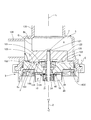
- FIG. 1 is an external perspective view of a pump device according to an embodiment of the present invention.
- FIG. 2 is a cross-sectional view taken along line AA of the pump device of FIG. It is the disassembled perspective view which looked at the pump apparatus from the output side of the motor. It is the disassembled perspective view which looked at the pump apparatus which removed the case body from the output side of the motor. It is the disassembled perspective view which looked at the pump apparatus which removed the case body from the non-output side of the motor. It is the disassembled perspective view which looked at the motor which drives an impeller from the output side. It is a disassembled perspective view of the motor which removed the cover member. It is a disassembled perspective view of a rotor. It is a perspective view of a stator. It is a perspective view of a cover member. It is the side view, top view, and bottom view of an impeller. It is a partial expanded sectional view of a pump chamber periphery. It is explanatory drawing of a suction
- FIG. 1 is an external perspective view of a pump device according to an embodiment of the present invention.
- FIG. 2 is a cross-sectional view of the pump device of FIG.
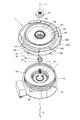
- FIG. 3 is an exploded perspective view of the pump device viewed from the output side of the motor.
- the pump device 1 includes a motor 3 having an output shaft 2 and a case body 5 that covers an output-side end wall portion 4 of the motor 3 from which the output shaft 2 protrudes.
- a pump chamber 6 defined by the end wall portion 4 of the motor 3 and the case body 5, and an impeller 7 attached to the output shaft 2 of the motor 3 and disposed in the pump chamber 6.
- the case body 5 is provided with a fluid suction port 8 and a fluid discharge port 9 communicating with the pump chamber 6.
- the fluid suction port 8 is formed coaxially with the axis L of the output shaft 2.
- the fluid discharge port 9 opens in the radial direction orthogonal to the axis L.
- the axis L direction of the output shaft of the motor constituting the pump device is defined as the Z-axis direction.
- the + Z direction is on the output side of the motor, and for the sake of convenience in this specification, it is the upper side and the upper side.
- the ⁇ Z direction is the counter-output side of the motor, and in this specification, for the sake of convenience, the lower side and the lower side are used.
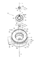
- FIG. 4 is an exploded perspective view of the pump device with the case body removed when viewed from the output side of the motor.
- FIG. 5 is an exploded perspective view of the pump device with the case body removed when viewed from the opposite output side of the motor.
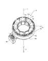
- FIG. 6 is a perspective view of the motor 3 with the cover member 14 removed.
- FIG. 7 is an exploded perspective view of the motor 3 with the cover member 14 removed.
- FIG. 8 is an exploded perspective view of the rotor.
- the motor 3 is a DC brushless motor. As shown in FIG. 6, the motor 3 includes a rotor 10, a stator 11, and a housing 12 that houses these. 4 and 5, the housing 12 includes a resin sealing member 13 that covers the stator 11 from the ⁇ Z direction side, and a cover member 14 that covers the resin sealing member 13 from the upper side.
- the cover member 14 constitutes the end wall portion 4 on the output side of the motor 3 from which the output shaft 2 protrudes.
- the resin sealing member 13 holds a first bearing member 15 that rotatably supports the lower end portion of the output shaft 2.
- the cover member 14 holds a second bearing member 16 that rotatably supports the middle of the output shaft 2 of the rotor 10.
- the cover member 14 is covered with the case body 5 from above.
- the rotor 10 includes an output shaft 2, a magnet 20 that surrounds the output shaft 2, and a holding member 21 that holds the output shaft 2 and the magnet 20.
- the output shaft 2 is made of metal, and in this example is made of stainless steel. As shown in FIG. 8, the output shaft 2 includes an annular groove 23 slightly below the center in the Z-axis direction. An E-ring 24 (first metal member) is attached to the annular groove 23. The E ring 24 is a metal plate-like member. The E-ring 24 is fixed to the annular groove 23 of the output shaft 2 and protrudes from the output shaft 2 to the outer peripheral side. Further, the output shaft 2 includes a first knurl forming portion 25 having a predetermined length below the annular groove 23. Further, the output shaft 2 includes a second knurl forming portion 26 having a predetermined length from the upper end portion toward the lower side.
- the second knurl forming portion 26 is a portion that protrudes upward from the housing 12 of the motor 3 and reaches the pump chamber 6, and is an attachment portion to which the impeller 7 is attached.
- a first supported portion 27 supported by the first bearing member 15 is provided below the first knurl forming portion 25 in the output shaft 2.
- a second supported portion 28 supported by the second bearing member 16 is provided between the annular groove 23 and the second knurl forming portion 26 in the output shaft 2.
- the magnet 20 has an annular shape and is arranged coaxially with the output shaft 2.
- the magnet 20 is disposed on the outer peripheral side of the first knurl forming portion 25.
- N poles and S poles are alternately magnetized in the circumferential direction.
- an end portion on the inner peripheral side of the upper surface of the magnet 20 has a tapered surface 31 inclined downward toward the inner peripheral side, and an annular surface extending from the lower end of the tapered surface 31 to the inner peripheral side. 33 are provided continuously. Further, similarly to the upper surface, a tapered surface 31 inclined upward toward the inner peripheral side and an annular surface extending from the upper end edge of the tapered surface 31 toward the inner peripheral side are also provided on the inner peripheral end portion of the lower surface of the magnet 20. 33 are provided continuously. A plurality of concave portions 32 are formed in the upper and lower tapered surfaces 31 at equal angular intervals in the circumferential direction. The inner peripheral surfaces of the plurality of recesses 32 have a spherical shape.
- the outer peripheral side of the tapered surface 31 is an annular surface 34 orthogonal to the axis L.
- the outer peripheral side of the tapered surface 31 is an annular surface 34 orthogonal to the axis L.
- the holding member 21 is a resin molded product, and holds the portion including the first knurl forming portion 25 of the output shaft 2 from the outer peripheral side.
- the holding member 21 includes a cylindrical output shaft holding portion 38, an annular magnet holding portion 39 that holds the magnet 20 on the outer peripheral side of the output shaft holding portion 38, and a radial direction extending radially from the output shaft holding portion 38.
- a plurality of connecting portions 40 for connecting the output shaft holding portion 38 and the magnet holding portion 39 are provided.
- the magnet holding portion 39 includes a magnet holding cylinder portion 41 that covers the inner circumferential surface 37 of the magnet 20 from the inner circumference side, and an annular first magnet holding collar portion 42 that extends outward from the lower end portion of the magnet holding cylinder portion 41. And an annular second magnet holding rod portion 43 that spreads outward from the upper end portion of the magnet holding cylinder portion 41.
- the first magnet holding collar portion 42 covers the lower surface portion excluding the outer peripheral edge portion of the lower surface of the magnet 20.
- the second magnet holding rod portion 43 covers the upper surface portion excluding the outer peripheral edge portion of the upper surface of the magnet 20. Further, as shown in FIG.
- the first magnet holding collar portion 42 and the second magnet holding collar portion 43 are provided on the outer peripheral side of the tapered surface covering portion 39a and the tapered surface covering portion 39a.
- An annular plate portion 39b that is positioned and overlaps the annular surface 34 is provided.
- the tapered surface covering portion 39a has a thickness in the Z-axis direction as compared with the annular plate portion 39b.
- the first magnet holding collar portion 42 and the second magnet holding collar portion 43 have a shape along the upper surface and the lower surface of the magnet 20 and are in close contact with the inner circumferential surface of the inner circumferential surface of the recess 32.
- the E ring 24 fixed to the output shaft 2 is held by the holding member 21 in a state where a portion protruding from the output shaft 2 to the outer peripheral side is embedded in the upper surface of the output shaft holding portion 38.
- the upper surface of the portion protruding from the output shaft 2 to the outer peripheral side is exposed upward from the output shaft holding portion 38.
- the upper surface of the E ring 24, the upper surface of the output shaft holding portion 38, and the upper surface of the connection portion 40 are located on the same plane orthogonal to the axis L.
- the rotor 10 includes a first bearing plate 45 held on the lower end side of the holding member 21 and a second bearing plate 46 (second metal member) held on the upper end side of the holding member 21.
- the first bearing plate 45 and the second bearing plate 46 are annular metal plates.
- the first bearing plate 45 and the second bearing plate 46 include a plurality of notches 47 on the outer peripheral edge. Thereby, the 1st bearing board 45 and the 2nd bearing board 46 are provided with an unevenness
- the notches 47 are formed at six equiangular intervals. Each notch 47 formed in the first bearing plate 45 and the second bearing plate 46 faces each connection portion 40 in the Z-axis direction.
- the first bearing plate 45 is fixed to the holding member 21 with the output shaft 2 passing through the center hole 48 and covers the connection portion 40 and the output shaft holding portion 38 from the lower end side of the holding member 21. As shown in FIG. 2, the lower surface of the first bearing plate 45 is orthogonal to the axis L when the first bearing plate 45 is fixed to the holding member 21.
- the second bearing plate 46 is fixed to the holding member 21 with the output shaft 2 passing through the center hole 48, and covers the connecting portion 40, the output shaft holding portion 38 and the E-ring 24 from above the holding member 21.
- the second bearing plate 46 and the E ring 24 are in surface contact.
- the upper surface of the second bearing plate 46 is orthogonal to the axis L.
- the upper surface of the second bearing plate 46 is a rotor-side sliding surface 46 a that is in sliding contact with the second bearing member 16 from below.
- the holding member 21 is formed by insert molding in which the output shaft 2 to which the E-ring 24 is attached and the magnet 20 are placed in a mold and resin is injected.
- the first bearing plate 45 and the first bearing plate 45 are held by the holding member 21 after the insert molding.
- the output shaft 2 is passed through the center hole 48 of the first bearing plate 45, and the lower end side connection portion 40 and the lower end side output shaft of the holding member 21.
- the first bearing plate 45 is stacked on the holding portion 38. Thereafter, the portion of the holding member 21 located on the outer peripheral side of the first bearing plate 45 is plastically deformed by heat to cover the outer peripheral side portion of the lower surface of the first bearing plate 45, and the resin is applied to each notch 47. Get in. Thereby, the annular plastic deformation part 49 which covers the outer periphery of the 1st bearing board 45 from a lower side and an outer peripheral side is provided in the lower surface of the holding member 21. As shown in FIG. The first bearing plate 45 is held by the connecting portion 40 on the lower end side of the holding member 21, the output shaft holding portion 38 on the lower end side, and the plastic deformation portion 49.
- the output shaft 2 is passed through the center hole 48 of the second bearing plate 46, and the connection portion 40 on the upper end side of the holding member 21 and the upper end side thereof.
- the second bearing plate 46 is overlaid on the output shaft holding portion 38, and the lower surface of the second bearing plate 46 is in surface contact with the upper surface of the E-ring 24.
- a portion of the holding member 21 located on the outer peripheral side of the second bearing plate 46 is plastically deformed by heat to cover the outer peripheral side portion of the upper surface of the second bearing plate 46, and resin is applied to each notch 47. Get in.
- an annular plastic deformation portion 49 that covers the outer peripheral edge of the second bearing plate 46 from the upper side and the outer peripheral side is formed on the upper surface of the holding member 21.
- the second bearing plate 46 is held by the connecting portion 40 on the upper end side of the holding member 21, the output shaft holding portion 38 on the upper end side, the upper surface of the E ring 24, and the plastic deformation portion 49.
- FIG. 9 is a perspective view of the stator 11.
- the stator 11 connects an annular stator core 51 positioned on the outer peripheral side of the rotor 10, a plurality of coils 53 wound around the stator core 51 via an insulator 52, and a power supply line for supplying power to each coil 53.
- Connector 54 The stator 11 connects an annular stator core 51 positioned on the outer peripheral side of the rotor 10, a plurality of coils 53 wound around the stator core 51 via an insulator 52, and a power supply line for supplying power to each coil 53.
- Connector 54 is a perspective view of the stator 11.
- the stator core 51 is a laminated core formed by laminating thin magnetic plates made of a magnetic material. As shown in FIG. 9, the stator core 51 includes an annular portion 56 and a plurality of salient pole portions 57 that protrude radially inward from the annular portion 56.
- the plurality of salient pole portions 57 are formed at an equiangular pitch, and are arranged at a constant pitch in the circumferential direction. In this example, the plurality of salient pole portions 57 are formed at an angular pitch of 40 ° with the axis L as the center.
- the stator core 51 includes nine salient pole portions 57.
- the inner peripheral side end surface 57a of the salient pole portion 57 is an arc surface centered on the axis L, and is opposed to the outer peripheral surface of the magnet 20 of the rotor 10 with a slight gap.
- Each insulator 52 is formed of an insulating material such as resin.
- Each insulator 52 is formed in a cylindrical shape with a flange having flanges at both ends in the radial direction, and the salient poles so that the axial direction of the insulator 52 formed in the cylindrical shape matches the radial direction of the stator 11. It is attached to the part 57.
- Each of the coils 53 is wound around each of the plurality of salient pole portions 57 via the insulator 52. As shown in FIG. 2, each coil 53 wound around the insulator 52 projects in the Z-axis direction toward the outside in the radial direction.
- the insulator 52 partially covers the upper surface of the annular portion 56 of the stator core 51, but the outer peripheral edge portion 56 a of the upper surface of the annular portion 56 is not covered with the insulator 52. Similarly, the insulator 52 partially covers the lower surface of the annular portion 56 of the stator core 51, but the outer peripheral edge portion 56 b of the lower surface of the annular portion 56 is not covered with the insulator 52.
- each salient pole portion 57 protrudes from the insulator 52 to the inner peripheral side.
- a portion of each salient pole portion 57 exposed from the insulator 52 to the inner peripheral side is an axial end surface orthogonal to the axis L. 57b.
- a connector 54 to which a wiring for supplying power to the coil 53 is detachably connected is integrally formed in one of the plurality of insulators 52.
- the resin sealing member 13 includes a disk-shaped sealing member bottom portion 65 that covers the coil 53, the insulator 52, and the stator core 51 from below.
- the resin sealing member 13 includes a sealing member projecting portion 66 extending from the sealing member bottom portion 65 to the outer peripheral side and covering the connector 54, and extending upward from the sealing member bottom portion 65 to the coil 53, the insulator 52, and And a sealing member cylinder portion 67 covering the stator core 51.
- a bearing member holding recess 68 is provided at the center of the upper surface of the sealing member bottom 65.
- the bearing member holding recess 68 holds the first bearing member 15 that rotatably supports the rotor 10 below the magnet 20.
- the bearing member holding recess 68 is a circular recess and includes a groove 68a extending in the Z-axis direction in a portion of the inner peripheral surface of the recess in the circumferential direction.
- the first bearing member 15 is made of resin, and includes a cylindrical support portion 70 having a through hole through which the output shaft 2 passes, and a flange portion 71 that extends from the upper end of the support portion 70 to the outer peripheral side.
- a convex portion 70 a extending at a constant width in the Z-axis direction is formed on a part of the outer peripheral surface of the support portion 70 in the circumferential direction.
- the contour of the flange portion 71 is an arc-shaped arc contour portion 71a when viewed from the Z-axis direction, and a linear contour portion 71b that linearly connects one end and the other end in the circumferential direction of the arc contour portion 71a. It is D-shape provided with.
- the straight contour portion 71b is located on the opposite side of the convex portion 70a across the through hole.
- the support portion 70 is inserted into the bearing member holding recess 68 in a state where the positions of the convex portion 70 a of the support portion 70 and the groove 68 a of the bearing member holding recess 68 are matched. As shown in FIG. 2, the first bearing member 15 is inserted and fixed to the bearing member holding recess 68 until the flange 71 comes into contact with the sealing member bottom 65 from above. In the state where the first bearing member 15 is fixed to the bearing member holding recess 68, the upper end surface of the flange portion 71 is orthogonal to the axis L.
- the support portion 70 functions as a radial bearing of the output shaft 2
- the flange portion 71 functions as a thrust bearing of the rotor 10. That is, the upper end surface of the flange portion 71 is a sliding surface 72 with which the rotor 10 is in sliding contact.
- the lower surface of the first bearing plate 45 fixed to the holding member 21 of the rotor 10 is in sliding contact with the sliding surface 72 of the first bearing member 15. That is, the lower surface of the first bearing plate 45 is a rotor-side sliding surface 45 a that is in sliding contact with the sliding surface 72 of the first bearing member 15. Note that grease is applied to the sliding surface 72.
- the sealing member tube portion 67 includes a large-diameter tube portion 81 and a small-diameter tube portion 82 having a smaller outer diameter than the large-diameter tube portion 81 from the lower side toward the upper side.
- the outer diameter of the large-diameter cylindrical portion 81 is larger than the outer diameter of the annular portion 56 of the stator core 51
- the outer diameter of the small-diameter cylindrical portion 82 is smaller than the outer diameter of the annular portion 56 of the stator core 51.
- An opening 83 that exposes the outer peripheral edge portion 56 a of the annular portion 56 of the stator core 51 upward from the resin sealing member 13 is formed at the boundary portion between the large diameter cylindrical portion 81 and the small diameter cylindrical portion 82 in the sealing member cylindrical portion 67. Is provided. Further, an annular end face 84 orthogonal to the axis L is provided on the outer peripheral side of the opening 83 in the resin sealing member 13. The outer peripheral edge portion of the stator core 51 exposed from the opening 83 and the annular end surface 84 are located on the same plane orthogonal to the axis L.
- the upper end portion of the large-diameter cylindrical portion 81 is provided with four locking projections 85 that protrude to the outer peripheral side at equal angular intervals.
- the inner peripheral surface of the sealing member cylinder portion 67 includes a small-diameter inner peripheral surface portion 67a from the lower side toward the upper side, and a large-diameter inner peripheral surface portion 67b having a larger inner diameter than the small-diameter inner peripheral surface portion 67a. .
- the radius of curvature of the small-diameter inner peripheral surface portion 67 a is substantially equal to the curvature radius of the inner peripheral side end surface 57 a of the salient pole portion 57.
- the small-diameter inner peripheral surface portion 67a is provided with a plurality of openings 86 that expose the inner peripheral side end surfaces 57a of the salient pole portions 57 of the stator core 51 to the inner peripheral side.
- the small-diameter inner peripheral surface portion 67a is provided with a notch portion 87 that exposes a part of the axial end surface 57b of each salient pole portion 57 to the upper side. That is, nine notches 87 are formed in the small-diameter inner peripheral surface portion 67a at an angular pitch of 40 ° centering on the axis L.
- the notch 87 is a groove extending in the Z-axis direction from the edge of the opening 86 to the upper end edge of the small-diameter inner peripheral surface portion 67a.
- the cross-sectional shape of the notch 87 is an arc shape.
- each salient pole portion 57 exposed from the opening 86 continues to the small diameter inner peripheral surface portion 67a without a step.
- a rust preventive agent 88 is applied to the inner peripheral side end face 57 a of each salient pole portion 57 exposed from the opening 86.
- a rust inhibitor 88 is also applied to the exposed portion 57 c of the axial end surface 57 b of each salient pole portion 57 exposed from the notch 87.
- an epoxy paint is used as the rust inhibitor 88.
- other paints except an epoxy paint, rust preventive oil, and an adhesive agent can be used as the rust preventive agent 88.
- the resin sealing member 13 is formed of BMC (Bulk Molding Compound).
- the resin sealing member 13 is formed by placing the stator 11 in a mold and injecting and curing the resin into the mold. That is, the resin sealing member 13 is integrally formed with the stator 11 by insert molding.
- the inner peripheral side end face 57a of each salient pole portion 57 of the stator core 51 is exposed from the resin sealing member 13. Therefore, in insert molding, a cylindrical mold part is provided in the mold, and the outer peripheral surface of the mold part is brought into contact with the inner peripheral side end face 57a of each salient pole part 57, so that the stator core 51 in the radial direction. Can be positioned. Further, the resin sealing member 13 exposes a part (exposed portion 57 c) of the axial end surface 57 b of each salient pole portion 57 of the stator core 51 to the upper side. Further, the resin sealing member 13 exposes the outer peripheral edge portion 56 a of the annular portion 56 of the stator core 51 to the upper side.
- the first abutting portion that can abut against the axial end surface 57b of each salient pole portion 57 from the upper side and the second abutable against the outer peripheral edge portion of the annular portion 56 from the upper side in the mold.
- a contact portion is provided, and the stator core 51 can be positioned in the Z-axis direction by bringing the first contact portion and the second contact portion into contact with the stator core 51.
- the resin sealing member 13 can be molded by injecting resin into the mold in a state where the stator core 51 disposed in the mold is positioned in the radial direction and the Z-axis direction. Thereby, the precision of the relative position of the stator core 51 and the resin sealing member 13 improves.
- the notch part 87 provided in the internal peripheral surface of the sealing member cylinder part 67 is a trace of the 1st contact part provided in the metal mold
- FIG. 10A is a perspective view when the cover member 14 is viewed from above
- FIG. 10B is a perspective view when the cover member 14 is viewed from below.
- the cover member 14 is made of resin and is fixed to the upper side of the resin sealing member 13.
- the cover member 14 includes a circular plate-shaped cover member ceiling portion 91 and a cover member cylinder portion 92 extending in the ⁇ Z direction from the cover member ceiling portion 91.
- the cover member ceiling portion 91 includes a through-hole 93 that penetrates in the Z-axis direction at the center.
- a circular concave portion 94 surrounding the through hole 93 is provided in the central portion of the upper surface of the cover member ceiling portion 91.
- An annular seal member 95 is disposed in the circular recess 94. The output shaft 2 passes through the seal member 95.
- an inner annular protrusion 101 is provided at the opening edge of the circular recess 94 in the cover member 14.
- An outer annular protrusion 102 is provided on the outer peripheral side of the inner annular protrusion 101 in the cover member 14.
- a flat inner annular surface 103 (opposing surface) orthogonal to the axis L is provided between the inner annular protrusion 101 and the outer annular protrusion 102.
- the protruding dimension of the outer annular protrusion 102 from the inner annular surface 103 is larger than the protruding dimension of the inner annular protrusion 101 from the inner annular surface 103.
- a first step 107 and a second step 108 are provided on the outer peripheral surface of the outer annular protrusion 102.
- an O-ring 109 is attached to the first step 107 located on the upper side.
- an outer annular surface 104 is provided on the outer peripheral side of the outer annular protrusion 102 in the cover member 14.
- An annular protrusion 105 is provided on the outer peripheral side of the outer annular surface 104.
- locking claws 106 that protrude inwardly at four locations in the circumferential direction.
- the outer peripheral side of the outer annular protrusion 102 in the cover member 14 is a case body attaching portion for attaching the case body 5 to the motor 3 (cover member 14).
- a bearing member holding cylinder 97 coaxial with the through hole 93 is provided at the center thereof.
- an outer annular rib 98 is provided on the lower surface of the cover member ceiling portion 91 along the outer periphery of the circle.
- a circular inner annular rib 99 is provided between the bearing member holding cylinder 97 and the outer annular rib 98 on the lower surface of the cover member ceiling portion 91.
- an inner rib 100a that extends radially from the bearing member holding cylinder part 97 and reaches the inner annular rib 99 is provided.
- an outer rib 100b that extends radially from the inner annular rib 99 and reaches the outer annular rib 98 is provided.
- the bearing member holding cylinder 97, the outer annular rib 98 and the inner annular rib 99 are coaxial.
- the lower end surface of the bearing member holding cylinder 97, the lower end surface of the outer annular rib 98, and the lower end surface of the inner annular rib 99 are planes orthogonal to the axis L.
- the protruding amount of the bearing member holding cylinder 97 from the lower surface of the cover member ceiling 91 is larger than the protruding amount of the inner annular rib 99 from the lower surface of the cover member ceiling 91.
- the protruding amount of the inner annular rib 99 from the lower surface of the cover member ceiling portion 91 is larger than the protruding amount of the outer annular rib 98 from the lower surface of the cover member ceiling portion 91.
- the lower surface of the outer rib 100b and the lower surface of the outer annular rib 98 are on the same plane.
- the bearing member holding cylinder portion 97 includes a groove 97 a extending in the Z-axis direction in a part of the inner peripheral wall of the through hole 93 in the circumferential direction. As shown in FIG. 2, the second bearing member 16 is held in the center hole of the bearing member holding cylinder 97.
- the second bearing member 16 has the same members as the first bearing member 15 arranged upside down.
- the second bearing member 16 is made of resin, and includes a cylindrical support portion 70 having a through hole through which the output shaft 2 passes, and a flange portion 71 that extends from the lower end of the support portion 70 to the outer peripheral side.
- a convex portion 70 a extending at a constant width in the Z-axis direction is formed on a part of the outer peripheral surface of the support portion 70 in the circumferential direction.
- the contour of the flange portion 71 is an arc-shaped arc contour portion 71a when viewed from the Z-axis direction, and a linear contour portion 71b that linearly connects one end and the other end in the circumferential direction of the arc contour portion 71a. It is D-shape provided with.
- the straight contour portion 71b is located on the opposite side of the convex portion 70a with the through hole interposed therebetween.
- the support portion 70 is inserted into the bearing member holding cylinder portion 97 in a state where the convex portions 70 a of the support portion 70 and the positions of the grooves 97 a of the bearing member holding cylinder portion 97 are matched.
- the second bearing member 16 is in a state where the flange portion 71 is in contact with the cover member 14 (the lower surface of the bearing member holding cylinder portion 97 of the cover member ceiling portion 91) from below.
- the bearing member holding cylinder 97 is inserted and fixed.
- the upper end surface of the flange portion 71 is orthogonal to the axis L.
- the support portion 70 functions as a radial bearing of the output shaft 2
- the flange portion 71 functions as a thrust bearing of the rotor 10. That is, the lower end surface of the flange 71 is a sliding surface 72 with which the rotor 10 is in sliding contact.
- the upper surface of the second bearing plate 46 fixed to the holding member 21 of the rotor 10 is in sliding contact with the sliding surface 72 of the second bearing member 16. That is, the upper surface of the second bearing plate 46 is a rotor-side sliding surface 46 a that is in sliding contact with the sliding surface 72 of the second bearing member 16. Grease is applied to the sliding surface 72.
- the cover member cylinder portion 92 extends in the ⁇ Z direction from the outer peripheral side of the outer annular rib 98.
- the cover member cylinder portion 92 includes an upper annular cylinder portion 111 that overlaps the small diameter cylinder portion 82 of the resin sealing member 13 and covers from the outer peripheral side, and a large diameter cylinder portion 81 below the upper annular cylinder portion 111.
- the lower annular cylinder part 112 located in the outer peripheral side.
- an annular step portion 113 is provided between the upper annular tube portion 111 and the lower annular tube portion 112 on the inner peripheral surface of the cover member tube portion 92.
- the annular step 113 includes an annular surface 113a facing downward.
- the annular surface 113a is a plane orthogonal to the axis L.
- the lower annular cylindrical portion 112 is provided with locked portions 114 that are engaged with the locking protrusions 85 of the resin sealing member 13 at four locations in the circumferential direction.
- the cover member 14 is covered with the resin sealing member 13 from above in a state where the rotor 10 is disposed inside the resin sealing member 13 and the rotor 10 is supported by the first bearing member 15.
- an adhesive is applied to the outer peripheral edge portion of the upper surface of the resin sealing member 13.
- the cover member 14 When the cover member 14 is put on the resin sealing member 13, the lower end portion of the inner annular rib 99 is fitted into the inner peripheral side of the sealing member cylindrical portion 67 of the resin sealing member 13 as shown in FIG. 2. As a result, the cover member 14 and the resin sealing member 13 are positioned in the radial direction, and the axis L of the output shaft 2 and the center axis of the stator 11 coincide. Further, the annular surface 113 a of the annular step 113 of the cover member cylinder 92 is brought into contact with the annular end surface 84 between the large diameter cylinder portion 81 and the small diameter cylinder portion 82 of the resin sealing member 13. Thereby, the cover member 14 is positioned with the resin sealing member 13 in the Z-axis direction.
- the cover member 14 and the resin sealing member 13 are rotated relative to each other in the circumferential direction, and the locking protrusion 85 of the resin sealing member 13 and the locked portion 114 of the cover member 14 are engaged.
- the cover member ceiling part 91 covers the rotor 10 and the resin sealing member 13 from above with the output shaft 2 penetrating in the Z-axis direction.
- the seal member 95 disposed in the circular concave portion 94 of the cover member ceiling portion 91 seals between the output shaft 2, the cover member 14, and the second bearing member 16.
- the annular tube portion 111 on the upper side of the cover member tube portion 92 surrounds the small-diameter tube portion 82 of the resin sealing member 13 from the outer peripheral side.
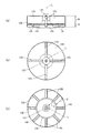
- FIG. 11A is a side view of the impeller
- FIG. 11B is a plan view of the impeller viewed from the + Z direction
- FIG. 11C is a bottom view of the impeller viewed from the ⁇ Z direction.
- the impeller 7 includes a cylindrical portion 121 having a center hole into which the output shaft 2 of the motor 3 is inserted, and a shroud that extends in a direction perpendicular to the axis L from the lower portion of the cylindrical portion 121. 122.
- the shroud 122 extends from the midway position in the Z-axis direction of the cylinder part 121 (a position closer to the lower side than the center of the cylinder part 121 in the Z-axis direction) to the outer peripheral side.
- the upper end portion of the center hole of the cylindrical portion 121 is sealed.
- the shroud 122 has a circular contour.
- the impeller 7 includes four front blades 123 on the end surface on the upper side of the shroud 122 (the side opposite to the end wall portion 4 of the motor 3).
- the four front blades 123 protrude upward from the shroud 122 and extend in the radial direction orthogonal to the axis L.
- Each front blade 123 has a substantially rectangular shape when viewed from the circumferential direction.
- An end on the inner peripheral side of each front blade 123 is continuous with the cylindrical portion 121.
- the outer peripheral end of each front blade 123 reaches the outer peripheral edge of the shroud 122.
- the four front blades 123 are provided at equiangular intervals around the axis L.
- each front blade 123 has a constant protrusion amount from the shroud 122 in the radial direction. Therefore, the upper end of the front blade 123 extends in parallel with the shroud 122.
- the impeller 7 includes an annular rib 124 that coaxially surrounds the cylindrical portion 121 on the lower side of the shroud 122 (the end wall portion 4 side of the motor 3), and eight back surfaces. And blades 125.
- the eight back blades 125 protrude downward from the shroud 122 and extend in the radial direction orthogonal to the axis L.
- Each back blade 125 has a substantially rectangular shape when viewed from the circumferential direction.
- An end on the inner peripheral side of each back blade 125 is continuous with the annular rib 124.
- the outer peripheral end of each back blade 125 reaches the outer peripheral edge of the shroud 122.
- the eight back blades 125 are provided at equal angular intervals around the axis L. That is, the eight back blades 125 are provided radially at an angular interval of 45 °. Further, every other four of the eight back blades 125 are provided at the same angular position as the front blade 123. Therefore, when viewed from the Z-axis direction, the four back blades 125 overlap the front blades 123.
- Each back blade 125 has a constant protrusion amount from the shroud 122 in the radial direction. Therefore, the lower end of the front blade 123 extends in parallel with the shroud 122. As shown in FIG.
- the protrusion amount A (height of the back blade 125) of the back blade 125 from the shroud 122 is the protrusion amount B (height of the front blade 123) of the front blade 123 from the shroud 122. 1/3 or less.
- the protruding amount A of the back blade 125 from the shroud 122 is smaller than the protruding amount of the annular rib 124 from the shroud 122.
- the protruding amount of the cylindrical portion 121 from the shroud 122 (the protruding amount of the portion located in the ⁇ Z direction of the shroud 122 in the cylindrical portion 121) is smaller than the protruding amount of the annular rib 124 and is larger than the protruding amount A of the back blade 125. large. Further, as shown in FIG.
- the length C length dimension of the back blade 125
- the length D length dimension of the back blade 125 from the outer peripheral surface of the annular rib 124 to the end on the outer peripheral side of the back blade 125 is equal to the cylindrical portion 121 and the annular rib. It is more than the distance D with respect to 124.
- the case body 5 includes a large-diameter annular fixing portion 131 and a small-diameter annular fixing portion 132 having a smaller outer diameter than the large-diameter annular fixing portion 131 from the lower side to the upper side.
- the cylindrical body 133 is coaxial with the large-diameter annular fixing part 131 and the small-diameter annular fixing part 132 and has an outer diameter smaller than that of the small-diameter annular fixing part 132, and an annular shape extending from the upper end of the cylindrical body 133 toward the inner peripheral side.
- annular plate part 134 and a suction pipe 135 extending coaxially with the cylindrical body part 133 from the center of the annular plate part 134 are provided.
- the case body 5 includes a discharge pipe 136 that extends radially outward from a portion of the cylindrical body portion 133 in the circumferential direction.
- the discharge pipe 136 communicates with the inside of the cylindrical body 133.
- the upper end opening of the suction pipe 135 is the fluid suction port 8
- the tip opening of the discharge pipe 136 is the fluid discharge port 9.
- the large-diameter annular fixing portion 131 is provided with convex portions 137 protruding to the outer peripheral side at four locations in the circumferential direction.
- the case body 5 is fixed to the cover member 14 of the motor 3 after the impeller 7 is attached to the tip portion of the output shaft 2.
- the outer annular protrusion 102 of the cover member 14 with the O-ring 109 attached is connected to the large-diameter annular fixing portion 131. And it inserts in the inner peripheral side of the small diameter annular fixing part 132. Then, the outer annular surface 104 of the cover member 14 is brought into contact with the lower end surface of the large-diameter annular fixing portion 131.
- the case body 5 is rotated in the circumferential direction, and the convex portion 137 is locked to the locking claw 106 of the cover member 14. Accordingly, the case body 5 is fixed to the cover member 14 with the O-ring 109 interposed in the radial direction between the case body 5 and the cover member 14.
- the pump chamber 6 is defined between the cover member 14 and the case body 5 as shown in FIG. Accordingly, the impeller 7 is arranged in the pump chamber 6.
- a peripheral wall surface 6a of the pump chamber 6 is configured.
- the inner surface of the annular plate portion 134 constitutes the ceiling surface 6 b (case body side facing surface) of the pump chamber 6.
- the ceiling surface 6 b is orthogonal to the axis L and is parallel to the inner annular surface 103 of the cover member 14.
- a region on the inner peripheral side of the outer annular protrusion 102 in the cover member 14 constitutes a bottom surface 6 c of the pump chamber 6.
- the fluid suction port 8 of the pump chamber 6 is located coaxially with the axis L of the output shaft 2 of the motor 3.
- the fluid discharge port 9 is provided outside in the radial direction orthogonal to the axis L of the output shaft 2.
- the inner annular surface 103 of the cover member 14 is an annular facing surface that overlaps with the rotation locus of the back blade 125 when viewed from the Z-axis direction.
- the inner annular surface 103 is a plane orthogonal to the axis L and is parallel to the back blade 125.
- FIG. 12 is a partially enlarged sectional view around the pump chamber 6.
- FIG. 13 is an explanatory diagram of a suction force generation mechanism. As shown in FIG. 13, when the motor 3 operates and the impeller 7 rotates, the fluid W flows from the fluid suction port 8 toward the front blades 123 of the impeller 7, flows through the pump chamber 6, It is discharged from the discharge port 9.
- a part W1 of the fluid W flowing through the pump chamber 6 is scraped to the outer peripheral side of the impeller 7 by the front blades 123 and then goes to the fluid discharge port 9 through the space between the impeller 7 and the case body 5. . Further, another part W2 of the fluid W flowing through the pump chamber 6 is scraped to the outer peripheral side of the impeller 7 by the front blade 123, and then the impeller 7 and the end wall portion 4 (cover member 14) of the motor 3 To the fluid discharge port 9.
- the impeller 7 has a back blade 125 that protrudes from the shroud 122 toward the end wall 4 (cover member 14) of the motor 3.
- the impeller 7 since the impeller 7 includes the back blade 125, the force F ⁇ b> 1 that moves the impeller 7 toward the case body 5 is suppressed, and the impeller 7 can be sucked toward the end wall portion 4 of the motor 3.
- the back blade 125 scrapes out the fluid W 3 from between the impeller 7 and the end wall portion 4 of the motor 3 to the outer peripheral side of the impeller 7.
- the fluid W ⁇ b> 3 scraped to the outer peripheral side from between the impeller 7 and the end wall portion 4 by the back blade 125 is scraped to the outer peripheral side of the impeller 7 by the front blade 123.
- the fluid W2 is suppressed from flowing between the impeller 7 and the end wall portion 4, an increase in pressure between the impeller 7 and the end wall portion 4 is suppressed. Therefore, the force F1 for moving the impeller 7 toward the case body 5 is reduced.
- the protruding amount A of the back blade 125 is 50% or more of the separation distance between the shroud 122 and the inner annular surface 103 of the cover member 14.
- wing 125 and the end wall part 4 (inner side annular surface 103) of the motor 3 can be narrowed, the impeller 7 and the end wall part 4 of the motor 3 by the back blade
- the protrusion amount A of the back blade 125 is increased, a larger suction force (negative pressure F2) can be generated.
- the first distance F between the back blade 125 and the inner annular surface 103 of the cover member 14 is the ceiling surface 6b (case body 5) facing the inner annular surface 103 of the cover member 14 in the Z-axis direction in the case body 5.
- the annular plate portion 134) and the front blade 123 is shorter than the second distance G. That is, in the Z-axis direction, the distance between the back blade 125 and the end wall portion 4 of the motor 3 is narrower than the distance between the front blade 123 and the case body 5. Therefore, it is easy to scrape out the fluid W3 from between the back blade 125 and the end wall 4 of the motor 3, and it is easy to generate the negative pressure F2.
- the fluid W ⁇ b> 3 can be easily scraped from between the impeller 7 and the end wall portion 4 of the motor 3. Therefore, it is easy to suppress the force F1 that moves the impeller 7 toward the case body 5, and it is easy to generate the negative pressure F2.
- the impeller 7 includes a cylindrical portion 121 protruding from the shroud 122 toward the end wall portion 4 and an annular rib 124. Therefore, the impeller 7 can be held so as not to be inclined by the output shaft 2 inserted into the cylindrical portion 121. Further, the annular rib 124 can prevent or suppress the dust contained in the fluid W from reaching the periphery of the output shaft 2. Furthermore, since the length dimension from the outer peripheral surface of the annular rib 124 to the end on the outer peripheral side in the back blade 125 is not less than the interval between the cylindrical portion 121 and the annular rib 124, the length dimension in the radial direction of the back blade 125 can be secured. . Therefore, it is easy to scrape out the fluid W3 from between the impeller 7 and the end wall portion 4 of the motor 3 by the back blade 125.
- the back blade 125 functions as a suction force generation mechanism 140 that generates a suction force (negative pressure F2) for sucking the impeller 7 toward the end wall portion 4 side. Therefore, it is possible to suppress the impeller 7 from being biased toward the case body 5 when the fluid W flows through the pump chamber 6. Thereby, since it can suppress that the output shaft 2 to which the impeller 7 is connected is urged toward the case body 5, the rotor 10 including the output shaft 2 in the motor 3 is in sliding contact with the rotor 10 from the output side. Pressing against the second bearing member 16 can be suppressed. Therefore, heat generated by sliding between the rotor 10 and the second bearing member 16 can be suppressed.
- the resin holding member 21 that holds the output shaft 2 from the outer peripheral side holds the E ring 24 (first metal member) that is fixed to the output shaft 2 and protrudes from the output shaft 2 to the outer peripheral side. is doing. Therefore, it is possible to prevent or suppress the position of the holding member 21 with respect to the output shaft 2 from changing in the Z-axis direction (Z-axis direction). Thereby, since the position of the magnet 20 held by the holding member 21 can be prevented or suppressed from changing in the Z-axis direction, the rotation accuracy of the rotor 10 can be maintained.
- the holding member 21 holds the E ring 24 fixed to the output shaft 2, the heat generated by the sliding between the second bearing member 16 and the rotor 10 is transferred to the output shaft 2 via the E ring 24. Can be released to the side. Therefore, it is possible to prevent or suppress the resin-made holding member 21 from being deformed by the heat generated by the sliding between the second bearing member 16 and the rotor 10.
- the rotor 10 includes a metal second bearing plate 46 (second metal member) held by the holding member 21, and the second bearing plate 46 is a sliding surface of the second bearing member 16.
- the rotor-side sliding surface 46 a that is in sliding contact with 72 is provided.
- the part which slides with the 2nd bearing member 16 in the rotor 10 consists of metal, it does not deform
- the E-ring 24 fixed to the output shaft 2 abuts on the second bearing plate 46 from the side opposite to the sliding surface 72. Therefore, even when the rotor 10 rotates, a force that urges the rotor 10 toward the second bearing member 16 works to cause the second bearing plate 46 to be pressed against the second bearing member 16.
- the position of the second bearing plate 46 does not change in the direction away from the sliding surface 72 in the Z-axis direction, and the position of the rotor 10 can be prevented from changing in the Z-axis direction.
- the E-ring 24 comes into contact with the second bearing plate 46, the heat generated by the sliding between the second bearing member 16 and the rotor 10 is output from the second bearing plate 46 via the E-ring 24. Released on the axis 2 side.
- the output shaft 2 is made of metal. Therefore, the heat generated by the sliding between the rotor 10 and the second bearing member 16 is easily released through the output shaft 2.
- the second bearing plate 46 is held by the holding member 21 with the output shaft 2 passing through the center hole 48, and is not fixed to the output shaft 2. Accordingly, the second bearing plate 46 can be prevented from being distorted by being fixed to the output shaft 2. Thereby, since the flatness of the rotor side sliding surface 46a can be maintained, it becomes easy to ensure the rotational accuracy of the rotor 10.
- the number of back blades 125 is not limited to the above example, and may be reduced or increased. In this case, if the number of the back blades 125 is increased, the fluid W3 can be scraped out from between the impeller 7 and the end wall portion 4 of the motor 3 by the back blades 125. Therefore, the force F1 that moves the impeller 7 toward the case body 5 can be easily suppressed, and the suction force (negative pressure F2) generated between the impeller 7 and the end wall portion 4 of the motor 3 can be increased. it can. Moreover, the diameter C of the rear blade 125 may be changed by changing the diameter of the annular rib 124 of the impeller 7 from the above example.
- the back blade 125 extends linearly in the radial direction, but the back blade 125 may be inclined with respect to the radial direction.
- the back blade 125 can be inclined with respect to the rotation direction of the output shaft 2 so that the inner peripheral side is located on the front side in the rotation direction and the outer peripheral side is located on the rear side in the rotation direction.
- the shape of the back blade 125 may be an arc shape or the like.
- A Back blade protrusion amount
- B Front blade protrusion amount
- C Dimensions
- D Spacing
- F1 Negative pressure
- F2 Negative pressure (suction force)
- L Axis
- L Center axis
Landscapes
- Engineering & Computer Science (AREA)
- Mechanical Engineering (AREA)
- General Engineering & Computer Science (AREA)
- Structures Of Non-Positive Displacement Pumps (AREA)
Abstract
モータによりインペラを駆動して流体を流通させたときに、インペラがポンプ室を区画するケース体の側に引き寄せられることを抑制できるポンプ装置を提供すること。インペラ(7)はケース体(5)とモータ(3)の端壁部(4)により区画されたポンプ室(6)に配置される。インペラ(7)はシュラウド(122)からモータ(3)の端壁部(4)の側に突出する裏羽根(125)を有する。インペラ(7)が駆動されてポンプ室(6)を流体が流通すると、裏羽根(125)は、インペラ(7)とモータ(3)の端壁部(4)との間から流体(W3)を掻き出す。これにより、インペラ(7)とモータ(3)の端壁部(4)との間に負圧(F2)が発生するので、この負圧(F2)によって、インペラ(7)がモータ(3)の端壁部(4)の側に引き寄せられる。裏羽根(125)は当該インペラ(7)を端壁部(4)の側に吸引する吸引力(負圧(F2))を発生させる吸引力発生機構(140)として機能する。
Description
本発明は、ポンプ室内のインペラをモータにより駆動するポンプ装置に関する。
流体吸入口および流体吐出口を備えるポンプ室と、ポンプ室内に配置されたインペラと、インペラを回転させるモータとを備えるポンプ装置は、特許文献1に記載されている。同文献のポンプ装置では、モータは、ロータと、ロータの外周側に配置された円筒状のステータと、ハウジングと、を備える。ハウジングは、ロータとステータとの間を隔てる隔壁部材と、隔壁部材の外周側でステータを覆う樹脂製の封止部と、を備える。ポンプ室は、ハウジングと、ハウジングの上方に被せられたケース体と、によって区画されている。流体吸入口および流体吐出口はケース体に設けられている。
ロータは、筒状のスリーブと、スリーブの外周側に環状に配列された磁石と、スリーブと磁石とを保持する保持部材とを備える。スリーブには固定軸が挿入されており、ロータは固定軸に回転可能に支持されている。固定軸における軸線方向の途中には外周側に広がる軸受部材が取り付けられている。軸受部材はロータのスラスト軸受として機能するものであり、軸受部材には軸線方向の一方側からスリーブが摺接する。インペラは保持部材に固定されて、ロータとともにポンプ室内に位置する。
モータが動作してインペラが回転すると、流体吸入口から流体吐出口に向かってポンプ室内を流体が流れる。ここで、ポンプ室を通過する流体がインペラと隔壁部材との間に流入すると、これらの間の圧力が高まるので、インペラには、当該インペラをケース体の側に向かって移動させる力が働く。このような力によってインペラがケース体の側に付勢されると、ロータ(スリーブ)は軸受部材に押し付けられた状態となる。この結果、軸受部材とロータとの間には摺動によって大きな熱が発生するので、ロータを構成するスリーブや保持部材が樹脂製である場合、或いは、ポンプ室を区画している部材が樹脂製である場合には、これら樹脂製の部材が発生した熱により変形してしまう可能性がある。
そこで、本発明の課題は、このような点に鑑みて、モータによりインペラを駆動して流体を流通させたときに、インペラがポンプ室を区画するケース体の側に引き寄せられることを抑制できるポンプ装置を提供することにある。
上記の課題を解決するため、本発明のポンプ装置は、出力軸を備えるモータと、前記出力軸が突出する前記モータの出力側の端壁部に被せられたケース体と、前記端壁部と前記ケース体とによって区画されたポンプ室と、前記ケース体に設けられて前記ポンプ室に連通する流体吸入口および流体吐出口と、前記出力軸に取り付けられて前記ポンプ室に配置されたインペラと、前記モータにより前記インペラが駆動されて前記流体吸入口から前記流体吐出口に向かって前記ポンプ室を流体が流通すると当該インペラを前記端壁部の側に吸引する吸引力を発生させる吸引力発生機構と、を有することを特徴とする。
本発明のポンプ装置は、モータによりインペラが駆動されて流体吸入口から流体吐出口に向かってポンプ室を流体が流通したときに、吸引力発生機構がインペラをモータの端壁部の側に吸引する。従って、ポンプ室を通過する流体がインペラとモータの端壁部との間に流入し、これらの間の圧力が上昇してインペラをケース体の側に移動させる力が働く場合でも、その力を抑制できる。これにより、インペラが接続された出力軸が、ケース体の側に付勢される力を抑制できるので、モータにおいて、出力軸を備えるロータが、ロータに出力側から摺接する軸受部材に押し付けられることを抑制できる。よって、ロータと軸受部材との摺動により発生する熱を抑制できる。
本発明において、前記インペラは、前記出力軸の軸線と交差する方向に広がるシュラウドと、前記シュラウドから前記端壁部とは反対側に突出する表羽根と、前記シュラウドから前記端壁部の側に突出する裏羽根と、を有し、前記吸引力発生機構は、前記裏羽根を備えるものとすることができる。インペラがシュラウドからモータの端壁部の側に突出する裏羽根を備えれば、裏羽根によってインペラと端壁部との間から外周側に掻き出される流体が、インペラと端壁部との間に流入しようとする流体と衝突する。これにより、インペラと端壁部との間への流体の流入が抑制されるので、これらの間で圧力が上昇することを抑制できる。また、裏羽根によってインペラと端壁部との間から流体が外周側に掻き出されると、インペラと端壁部との間には負圧が発生する。従って、この負圧により、インペラをモータの端壁部の側に吸引できる。すなわち、インペラの裏羽根は、インペラを端壁部の側に吸引する吸引力を発生させる吸引力発生機構を構成する。
本発明において、インペラが駆動されてポンプ室を流体が流通する際に、裏羽根によってインペラと端壁部との間から流体を外周側に掻き出すためには、前記シュラウドは、前記軸線と垂直に広がり、前記裏羽根は、径方向において前記シュラウドから前記端壁部の側への突出量が一定であり、前記軸線方向から見た場合に前記裏羽根の回転軌跡と重なる前記端壁部の環状の対向面は、前記裏羽根と平行な平面であることが望ましい。
本発明において、前記裏羽根の突出量は、前記シュラウドと前記対向面との間の離間距離の50%以上であることが望ましい。このようにすれば、裏羽根とモータの端壁部との間の間隔を狭くすることができるので、裏羽根によってインペラと端壁部との間から流体を外周側に掻き出すことが容易となる。
本発明において、前記裏羽根と前記対向面との間の第1距離は、前記ケース体において前記軸線方向で前記対向面と対向するケース体側対向面と前記表羽根との間の第2距離よりも短いことが望ましい。すなわち、裏羽根とモータの端壁部との間の間隔が、表羽根とケース体との間の間隔よりも狭いことが望ましい。このようにすれば、裏羽根とモータの端壁部との間に、負圧を発生させやすい。
本発明において、裏羽根によってインペラと端壁部との間から流体を外周側に掻き出すためには、前記裏羽根は、前記軸線回りの等角度間隔で複数設けられていることが望ましい。
本発明において、前記インペラは、前記軸線と同軸で前記シュラウドから前記端壁部の側に突出する筒部と、前記筒部の外周側に当該筒部と同軸に設けられた環状リブと、を備え、前記出力軸は、前記筒部の中心穴に挿入されており、前記裏羽根は、前記環状リブの外周面から外周側に延びており、前記裏羽根における前記環状リブの外周面から外周側の端までの長さ寸法は、前記筒部と前記環状リブとの間隔以上であることが望ましい。このようにすれば、筒部に挿入された出力軸によりインペラを傾斜しないように保持できる。また、環状リブにより、出力軸の周囲に流体に含まれる塵などが達することを防止あるいは抑制できる。さらに、裏羽根における前記環状リブの外周面から外周側の端までの長さ寸法が筒部と環状リブとの間隔以上なので、裏羽根の径方向の長さ寸法を確保できる。これにより、裏羽根によってインペラと端壁部との間から流体を外周側に掻き出すことが容易となる。
本発明において、前記モータは、前記出力軸を備えるロータと、前記出力軸を回転可能に支持する軸受部材と、を備え、前記軸受部材は、前記反出力側から前記ロータが摺接する摺動面を備え、前記ロータは、前記出力軸を外周側から保持する樹脂製の保持部材と、前記保持部材に保持された磁石と、前記出力軸に固定されて当該出力軸から外周側に突出して前記保持部材に保持された第1金属部材と、前記摺動面に摺接するロータ側摺動面を備え、前記第1金属部材が前記反出力側から当接した状態で前記保持部材に保持された第2金属部材と、を備えることが望ましい。
このようにすれば、出力軸を外周側から保持する樹脂製の保持部材が、出力軸に固定されて出力軸から外周側に突出する第1金属部材を保持する。従って、出力軸に対する保持部材の位置が軸線方向で変化することを防止あるいは抑制できる。これにより、保持部材に保持された磁石の位置が軸線方向で変化してしまうことを防止あるいは抑制できるので、ロータの回転精度を維持できる。また、保持部材が出力軸に固定された第1金属部材を保持するので、軸受部材とロータとの摺動により発生した熱を、金属部材を介して、出力軸の側に放出できる。従って、軸受部材とロータとの摺動により発生した熱により、樹脂製の保持部材が変形することを防止或いは抑制できる。また、ロータにおいて軸受部材と摺動する部分は第2金属部材なので、摺動により発生する熱によって軸受部材と摺動する部分が変形することがない。さらに、第2金属部材には、出力軸に固定された第1金属部材が摺動面とは反対側から当接する。従って、出力軸がケース体の側に引き寄せられた場合でも、第2金属部材の位置が軸線方向で摺動面から離間する方向に変化することがない。さらに、第2金属部材には第1金属部材が当接するので、軸受部材とロータとの摺動により発生する熱は、第2金属部材から、第1金属部材を介して、出力軸の側に放出される。また、第2金属部材は、保持部材に保持されており、出力軸には固定されていない。従って、出力軸への固定によって第2金属部材が歪むことを回避できる。これによりロータ側摺動面の平面度を維持できるので、ロータの回転精度を確保することが容易となる。
本発明において、前記出力軸は、金属製であることが望ましい。このようにすれば、ロータと軸受部材との摺動により発生した熱を、出力軸を介して、放出しやすい。
本発明によれば、インペラの裏羽根が、ポンプ室内において、インペラとモータの端壁部との間から流体を外周側に掻き出す。従って、ポンプ室を流体が流通したときに、流体がインペラとモータの端壁部との間に流入し、これらの間の圧力が上昇することを抑制できる。また、インペラの裏羽根が、インペラとモータの端壁部との間から流体を外周側に掻き出すので、インペラとモータの端壁部との間には負圧が発生する。この負圧は、インペラをモータの側に引き寄せる吸引力なので、インペラがケース体の側に付勢されることが抑制される。この結果、インペラが接続された出力軸がケース体の側に付勢されることを抑制できるので、モータにおいて、出力軸を備えるロータが、ロータに出力側から摺接する軸受部材に押し付けられることを抑制できる。よって、ロータと軸受部材との摺動により発生する熱を抑制できる。
以下、図面を参照しながら、本発明の実施の形態のポンプ装置を説明する。
(ポンプ装置)
図1は本発明の実施の形態にかかるポンプ装置の外観斜視図である。図2は図1のポンプ装置のA-A線断面図である。図3はポンプ装置をモータの出力側から見た場合の分解斜視図である。図1、図2および図3に示すように、ポンプ装置1は、出力軸2を備えるモータ3と、出力軸2が突出するモータ3の出力側の端壁部4に被せられたケース体5と、モータ3の端壁部4とケース体5とによって区画されたポンプ室6と、モータ3の出力軸2に取り付けられてポンプ室6内に配置されたインペラ7とを備える。ケース体5にはポンプ室6に連通する流体吸入口8および流体吐出口9が設けられている。流体吸入口8は出力軸2の軸線Lと同軸に形成されている。流体吐出口9は軸線Lと直交する径方向に開口する。
図1は本発明の実施の形態にかかるポンプ装置の外観斜視図である。図2は図1のポンプ装置のA-A線断面図である。図3はポンプ装置をモータの出力側から見た場合の分解斜視図である。図1、図2および図3に示すように、ポンプ装置1は、出力軸2を備えるモータ3と、出力軸2が突出するモータ3の出力側の端壁部4に被せられたケース体5と、モータ3の端壁部4とケース体5とによって区画されたポンプ室6と、モータ3の出力軸2に取り付けられてポンプ室6内に配置されたインペラ7とを備える。ケース体5にはポンプ室6に連通する流体吸入口8および流体吐出口9が設けられている。流体吸入口8は出力軸2の軸線Lと同軸に形成されている。流体吐出口9は軸線Lと直交する径方向に開口する。
モータ3を駆動してインペラ7を回転させると、流体吸入口8から吸入された水などの流体はポンプ室6を流通して流体吐出口9から吐出される。以下の説明では、ポンプ装置を構成するモータの出力軸の軸線L方向をZ軸方向とする。+Z方向はモータの出力側であり本明細書では便宜上、上側、上方とする。-Z方向はモータの反出力側であり、本明細書では、便宜上、下側、下方とする。
(モータ)
図4はケース体を外したポンプ装置をモータの出力側から見た場合の分解斜視図である。図5はケース体を外したポンプ装置をモータの反出力側から見た場合の分解斜視図である。図6はカバー部材14を取り除いた状態のモータ3の斜視図である。図7はカバー部材14を取り除いた状態のモータ3の分解斜視図である。図8はロータの分解斜視図である。
図4はケース体を外したポンプ装置をモータの出力側から見た場合の分解斜視図である。図5はケース体を外したポンプ装置をモータの反出力側から見た場合の分解斜視図である。図6はカバー部材14を取り除いた状態のモータ3の斜視図である。図7はカバー部材14を取り除いた状態のモータ3の分解斜視図である。図8はロータの分解斜視図である。
モータ3はDCブラシレスモータである。図6に示すように、モータ3は、ロータ10と、ステータ11と、これらを収納するハウジング12とを備える。図4および図5に示すように、ハウジング12はステータ11を-Z方向の側から被う樹脂封止部材13と、樹脂封止部材13を上側から被うカバー部材14とを備える。カバー部材14は出力軸2が突出するモータ3の出力側の端壁部4を構成するものである。図2に示すように、樹脂封止部材13には、出力軸2の下側の端部分を回転可能に支持する第1軸受部材15が保持されている。カバー部材14には、ロータ10の出力軸2の中程を回転可能に支持する第2軸受部材16が保持されている。カバー部材14には上側からケース体5が被せられる。
(ロータ)
図7に示すように、ロータ10は、出力軸2と、出力軸2を囲む磁石20と、出力軸2および磁石20を保持する保持部材21とを備える。
図7に示すように、ロータ10は、出力軸2と、出力軸2を囲む磁石20と、出力軸2および磁石20を保持する保持部材21とを備える。
出力軸2は金属製であり、本例では、ステンレス鋼製である。図8に示すように、出力軸2はZ軸方向の中心よりも僅かに下側に環状溝23を備える。環状溝23にはEリング24(第1金属部材)が取り付けられている。Eリング24は金属製の板状の部材である。Eリング24は出力軸2の環状溝23に固定されて、出力軸2から外周側に突出する。また、出力軸2は、環状溝23の下側に所定長さの第1ローレット形成部25を備える。さらに、出力軸2は、上端部分から下側に向かう所定長さの第2ローレット形成部26を備える。第2ローレット形成部26は、モータ3のハウジング12から上側に突出してポンプ室6内に達する部分であり、インペラ7が取り付けられる取り付け部である。出力軸2における第1ローレット形成部25の下側には、第1軸受部材15により支持される第1被支持部27が設けられている。出力軸2における環状溝23と第2ローレット形成部26との間には第2軸受部材16により支持される第2被支持部28が設けられている。
磁石20は、環状であり、出力軸2と同軸に配置されている。磁石20は、第1ローレット形成部25の外周側に配置される。磁石20の外周面には、N極とS極とが周方向において交互に着磁されている。
図8に示すように、磁石20の上面の内周側の端部分には、内周側に向かって下側に傾斜するテーパー面31と、テーパー面31の下端から内周側に延びる環状面33とが連続して設けられている。さらに、磁石20の下面の内周側の端部分にも、上面と同様に、内周側に向かって上側に傾斜するテーパー面31と、テーパー面31の上端縁から内周側に延びる環状面33とが連続して設けられている。上下のテーパー面31には、周方向に等角度間隔で複数の凹部32が形成されている。複数の凹部32の内周面は球面形状を備える。磁石20の上面において、テーパー面31よりも外周側は、軸線Lと直交する環状面34となっている。磁石20の下面において、テーパー面31よりも外周側は、軸線Lと直交する環状面34となっている。
保持部材21は、樹脂成形品であり、出力軸2の第1ローレット形成部25を含む部分を外周側から保持する。保持部材21は、筒状の出力軸保持部38と、出力軸保持部38の外周側で磁石20を保持する環状の磁石保持部39と、出力軸保持部38から径方向を放射状に延びて出力軸保持部38と磁石保持部39との間を接続する複数の接続部40とを備える。
磁石保持部39は、磁石20の内周面37を内周側から被う磁石保持筒部分41と、磁石保持筒部分41の下端部分から外側に広がる円環状の第1磁石保持鍔部分42と、磁石保持筒部分41の上端部分から外側に広がる円環状の第2磁石保持鍔部分43と、を備える。図7に示すように、第1磁石保持鍔部分42は、磁石20の下面の外周縁部分を除く下面部分を被う。第2磁石保持鍔部分43は、磁石20の上面の外周縁部分を除く上面部分を被う。また、図8に示すように、第1磁石保持鍔部分42および第2磁石保持鍔部分43は、テーパー面31を被うテーパー面被い部39aと、テーパー面被い部39aの外周側に位置して環状面34に重なる環状板部39bを備える。テーパー面被い部39aは、環状板部39bと比較して、Z軸方向の厚みがある。なお、第1磁石保持鍔部分42および第2磁石保持鍔部分43は、磁石20の上面および下面に沿った形状をしており、凹部32の内周面の内周面に密着している。
ここで、出力軸2に固定されたEリング24は、出力軸2から外周側に突出する部分が出力軸保持部38の上面に埋め込まれた状態で、当該保持部材21に保持される。Eリング24において、出力軸2から外周側に突出している部分の上面は、出力軸保持部38から上側に露出している。Eリング24の上面と出力軸保持部38の上面および接続部40の上面とは、軸線Lと直交する同一平面上に位置する。
次に、ロータ10は、保持部材21の下端側に保持された第1軸受板45と、保持部材21の上端側に保持された第2軸受板46(第2金属部材)を備える。第1軸受板45および第2軸受板46は、円環状の金属板である。第1軸受板45および第2軸受板46は、外周縁に複数の切欠部47を備える。これにより、第1軸受板45および第2軸受板46は、外周縁に凹凸を備えるものとなっている。
切欠部47は等角度間隔で6か所に形成されている。第1軸受板45および第2軸受板46に形成された各切欠部47は、Z軸方向で各接続部40と対向する。第1軸受板45は、その中心孔48に出力軸2を貫通させた状態で保持部材21に固定されて当該保持部材21の下端側から接続部40および出力軸保持部38を被う。図2に示すように、第1軸受板45が保持部材21に固定された状態では、第1軸受板45の下面は軸線Lと直交する。第2軸受板46は、その中心孔48に出力軸2を貫通させた状態で保持部材21に固定されて当該保持部材21の上側から接続部40、出力軸保持部38およびEリング24を被う。第2軸受板46が保持部材21に固定された状態では、第2軸受板46とEリング24とは面接触する。第2軸受板46の上面は軸線Lと直交する。第2軸受板46の上面は第2軸受部材16に下側から摺接するロータ側摺動面46aである。
ここで、保持部材21の形成は、Eリング24が取り付けられた出力軸2および磁石20を金型内に配置して樹脂を注入するインサート成形により行われる。第1軸受板45および第1軸受板45は、インサート成形の後に、保持部材21に保持される。
保持部材21に第1軸受板45を保持させる際には、第1軸受板45の中心孔48に出力軸2を貫通させて、保持部材21の下端側の接続部40および下端側の出力軸保持部38に第1軸受板45を重ねる。その後に、保持部材21における第1軸受板45の外周側に位置する部分を熱により塑性変形させて、第1軸受板45の下面の外周側部分を被わせ、かつ、各切欠部47に樹脂を入り込ませる。これにより、保持部材21の下面には、第1軸受板45の外周縁を下側および外周側から被う環状の塑性変形部49が設けられる。第1軸受板45は、保持部材21の下端側の接続部40および下端側の出力軸保持部38と、塑性変形部49とにより保持される。
同様に、保持部材21に第2軸受板46を保持させる際には、第2軸受板46の中心孔48に出力軸2を貫通させて、保持部材21の上端側の接続部40および上端側の出力軸保持部38に第2軸受板46を重ねるとともに、第2軸受板46の下面をEリング24の上面に面接触させた状態とする。その後、保持部材21における第2軸受板46の外周側に位置する部分を熱により塑性変形させて、第2軸受板46の上面の外周側部分を被わせ、かつ、各切欠部47に樹脂を入り込ませる。これにより、図7に示すように、保持部材21の上面には、第2軸受板46の外周縁を上側および外周側から被う環状の塑性変形部49が形成される。第2軸受板46は、保持部材21の上端側の接続部40、上端側の出力軸保持部38、および、Eリング24の上面と、塑性変形部49とにより保持される。
(ステータ)
図9はステータ11の斜視図である。ステータ11は、ロータ10の外周側に位置する環状のステータコア51と、ステータコア51にインシュレータ52を介して巻回された複数のコイル53と、各コイル53への給電を行う給電線を接続するためのコネクタ54とを備える。
図9はステータ11の斜視図である。ステータ11は、ロータ10の外周側に位置する環状のステータコア51と、ステータコア51にインシュレータ52を介して巻回された複数のコイル53と、各コイル53への給電を行う給電線を接続するためのコネクタ54とを備える。
ステータコア51は、磁性材料からなる薄い磁性板が積層されて形成された積層コアである。図9に示すように、ステータコア51は、環状部56と、環状部56から径方向の内側に突出する複数の突極部57とを備える。複数の突極部57は等角度ピッチで形成されており、周方向において一定のピッチで配置されている。本例では、複数の突極部57は、軸線Lを中心とする40°の角度ピッチで形成されている。これにより、ステータコア51は9個の突極部57を備える。突極部57の内周側端面57aは、軸線Lを中心とする円弧面であり、ロータ10の磁石20の外周面と僅かなギャップを開けて対向する。
各インシュレータ52は樹脂等の絶縁性材料で形成されている。各インシュレータ52は、径方向の両端に鍔部を有する鍔付きの筒状に形成されており、筒状に形成されるインシュレータ52の軸方向とステータ11の径方向とが一致するように突極部57に取り付けられている。コイル53のそれぞれは、インシュレータ52を介して複数の突極部57のそれぞれに巻回される。図2に示すように、インシュレータ52に巻回された状態の各コイル53は、径方向の外側に向かってZ軸方向に突出している。なお、インシュレータ52は、ステータコア51の環状部56の上面を部分的に被っているが、環状部56の上面の外周縁部分56aはインシュレータ52により覆われていない。同様に、インシュレータ52は、ステータコア51の環状部56の下面を部分的に被っているが、環状部56の下面の外周縁部分56bはインシュレータ52により覆われていない。
各突極部57の先端部分は、インシュレータ52から内周側に突出している。各突極部57においてインシュレータ52から内周側に露出している部分(内周側端面57aとコイル53が巻回されている部分との間の部分)は、軸線Lと直交する軸方向端面57bを備える。複数のインシュレータ52のうちの一つのインシュレータ52には、コイル53への給電を行うための配線が着脱可能に接続されるコネクタ54が一体に形成されている。
(樹脂封止部材)
図5および図7に示すように、樹脂封止部材13は、コイル53、インシュレータ52、および、ステータコア51を下側から被う円盤形状の封止部材底部65を備える。また、樹脂封止部材13は、封止部材底部65から外周側に延びてコネクタ54を被う封止部材張出部66と、封止部材底部65から上側に延びてコイル53、インシュレータ52およびステータコア51を被う封止部材筒部67とを備える。
図5および図7に示すように、樹脂封止部材13は、コイル53、インシュレータ52、および、ステータコア51を下側から被う円盤形状の封止部材底部65を備える。また、樹脂封止部材13は、封止部材底部65から外周側に延びてコネクタ54を被う封止部材張出部66と、封止部材底部65から上側に延びてコイル53、インシュレータ52およびステータコア51を被う封止部材筒部67とを備える。
図7に示すように、封止部材底部65の上面の中心部分には、軸受部材保持凹部68が設けられている。軸受部材保持凹部68には、磁石20よりも下側でロータ10を回転可能に支持する第1軸受部材15が保持される。軸受部材保持凹部68は、円形の凹部であり、凹部の内周面の周方向の一部分にZ軸方向に延びる溝68aを備える。
第1軸受部材15は、樹脂製であり、出力軸2を貫通させる貫通穴を備える筒状の支持部70と、支持部70の上側の端から外周側に広がる鍔部71とを備える。支持部70の外周面の周方向の一部分には、Z軸方向に一定幅で延びる凸部70aが形成されている。鍔部71の輪郭は、Z軸方向から見た場合に円弧形状の円弧輪郭部分71aと、円弧輪郭部分71aの周方向の一方の端と他方の端とを直線状に接続する直線輪郭部分71bとを備えるD字形状である。直線輪郭部分71bは貫通穴を挟んで凸部70aと反対側に位置する。
第1軸受部材15は、支持部70の凸部70aと軸受部材保持凹部68の溝68aとの位置を一致させた状態で、支持部70が軸受部材保持凹部68に挿入される。そして、図2に示すように、第1軸受部材15は、鍔部71が上側から封止部材底部65に当接した状態となるまで挿入されて、軸受部材保持凹部68に固定される。第1軸受部材15が軸受部材保持凹部68に固定された状態で、鍔部71の上側の端面は軸線Lと直交する。ここで、支持部70は出力軸2のラジアル軸受として機能し、鍔部71はロータ10のスラスト軸受として機能する。すなわち、鍔部71の上側の端面は、ロータ10が摺接する摺動面72である。第1軸受部材15の摺動面72には、ロータ10の保持部材21に固定された第1軸受板45の下面が摺接する。すなわち、第1軸受板45の下面は、第1軸受部材15の摺動面72に摺接するロータ側摺動面45aである。なお、摺動面72にはグリスが塗布される。
次に、封止部材筒部67は、図7に示すように、下側から上側に向かって大径筒部分81と大径筒部分81よりも外径寸法の小さい小径筒部分82を備える。大径筒部分81の外径はステータコア51の環状部56の外径よりも大きく、小径筒部分82の外径はステータコア51の環状部56の外径よりも小さい。
封止部材筒部67における大径筒部分81と小径筒部分82との境界部分には、ステータコア51の環状部56の外周縁部分56aを樹脂封止部材13から上側に露出させる開口部83が設けられている。また、樹脂封止部材13における開口部83の外周側には、軸線Lと直交する環状端面84が設けられている。開口部83から露出するステータコア51の外周縁部分と環状端面84とは軸線Lと直交する同一平面上に位置する。大径筒部分81の上端部分には、等角度間隔で外周側に突出する4つの係止突起85が設けられている。
封止部材筒部67の内周面は、下側から上側に向かって小径内周面部分67aと、小径内周面部分67aよりも内径寸法の大きい大径内周面部分67bと、を備える。小径内周面部分67aの曲率半径は、突極部57の内周側端面57aの曲率半径とほぼ等しい。小径内周面部分67aには、ステータコア51の各突極部57の内周側端面57aを内周側に露出させる複数の開口部86が設けられている。また、小径内周面部分67aには、各突極部57の軸方向端面57bの一部分を上側に露出させる切欠部87が設けられている。すなわち、小径内周面部分67aには軸線Lを中心とする40°の角度ピッチで9個の切欠部87が形成されている。切欠部87は、開口部86の縁から小径内周面部分67aの上端縁までZ軸方向に延びる溝である。切欠部87の断面形状は円弧形状である。複数の切欠部87が設けられることにより、各突極部57の軸方向端面57bの先端部分における周方向の中央部分が、上側に露出する露出部分57cとなっている。
開口部86から露出する各突極部57の内周側端面57aは、小径内周面部分67aと段差なく連続する。開口部86から露出する各突極部57の内周側端面57aには防錆剤88が塗布されている。また、切欠部87から露出する各突極部57の軸方向端面57bの露出部分57cにも防錆剤88が塗布されている。本例では、防錆剤88としてエポキシ塗料を用いている。なお、防錆剤88としては、エポキシ塗料を除く他の塗料や、防錆油や、接着剤を用いることができる。
樹脂封止部材13は、BMC(Bulk Molding Compound)によって形成されている。本形態では、ステータ11を金型内に配置し、この金型内に樹脂を注入して硬化させることで樹脂封止部材13が形成される。すなわち、樹脂封止部材13はインサート成形によりステータ11と一体成形される。
ここで、本形態では、ステータコア51の各突極部57の内周側端面57aを樹脂封止部材13から露出させている。従って、インサート成形では、金型に円柱形状の金型部分を設けておき、その金型部分の外周面を各突極部57の内周側端面57aに当接させて、径方向でステータコア51を位置決めすることができる。また、樹脂封止部材13は、ステータコア51の各突極部57の軸方向端面57bの一部分(露出部分57c)を上側に露出させている。さらに、樹脂封止部材13は、ステータコア51の環状部56の外周縁部分56aを上側に露出させている。従って、インサート成形では、金型に、各突極部57の軸方向端面57bに上側から当接可能な第1当接部分と、環状部56の外周縁部分に上側から当接可能な第2当接部分を設けておき、これら第1当接部分および第2当接部分をステータコア51に当接させてZ軸方向でステータコア51を位置決めすることができる。すなわち、本形態では、金型内に配置したステータコア51を径方向およびZ軸方向で位置決めした状態で、金型内に樹脂を注入して樹脂封止部材13を成形できる。これにより、ステータコア51と樹脂封止部材13の相対位置の精度が向上する。
なお、封止部材筒部67の内周面に設けられた切欠部87は、金型に設けた第1当接部分の痕跡である。すなわち、インサート成形において、金型に設けた第1当接部をZ軸方向から軸線L各突極部57の軸方向端面57bに当接させているので、BMCが固化して樹脂封止部材13が形成されると、結果的に、第1当接部が当接していた部分が露出部分57cとなり、第1当接部が位置していた部分に切欠部87が設けられる。
(カバー部材)
図10(a)はカバー部材14を上側から見た場合の斜視図であり、図10(b)はカバー部材14を下側から見た場合の斜視図である。カバー部材14は、樹脂製であり、樹脂封止部材13の上側に固定される。
図10(a)はカバー部材14を上側から見た場合の斜視図であり、図10(b)はカバー部材14を下側から見た場合の斜視図である。カバー部材14は、樹脂製であり、樹脂封止部材13の上側に固定される。
図6および図10に示すように、カバー部材14は、円形板状のカバー部材天井部91と、カバー部材天井部91から-Z方向に延びるカバー部材筒部92とを備える。カバー部材天井部91は、中心にZ軸方向に貫通する貫通穴93を備える。図2、図6に示すように、カバー部材天井部91の上面の中央部分には、貫通穴93を囲む円形凹部94が設けられている。円形凹部94には円環状のシール部材95が配置される。シール部材95には出力軸2が貫通する。
図6に示すように、カバー部材14における円形凹部94の開口縁には内側環状突部101が設けられている。カバー部材14における内側環状突部101の外周側には外側環状突部102が設けられている。内側環状突部101と外側環状突部102との間には、軸線Lと直交する平坦な内側環状面103(対向面)が設けられている。内側環状面103からの外側環状突部102の突出寸法は、内側環状面103からの内側環状突部101の突出寸法よりも大きい。外側環状突部102の外周面には第1段部107および第2段部108が設けられている。図2に示すように、上側に位置する第1段部107にはOリング109が取り付けられている。
図6に示すように、カバー部材14における外側環状突部102の外周側には外側環状面104が設けられている。外側環状面104の外周側には環状突部105が設けられている。環状突部105の先端部分には、周方向の4か所に内周側に突出する係止爪106が設けられている。カバー部材14において外側環状突部102の外周側は、モータ3(カバー部材14)にケース体5を取り付けるためのケース体取付部である。
図10に示すように、カバー部材天井部91の下面には、その中央部分に貫通穴93と同軸の軸受部材保持筒部97が設けられている。また、カバー部材天井部91の下面には、その円形の外周縁に沿って外側環状リブ98が設けられている。さらに、カバー部材天井部91の下面には、軸受部材保持筒部97と外側環状リブ98との間に円形の内側環状リブ99が設けられている。軸受部材保持筒部97と内側環状リブ99との間には、軸受部材保持筒部97から放射状に延びて内側環状リブ99に達する内側リブ100aが設けられている。内側環状リブ99と外側環状リブ98との間には、内側環状リブ99から放射状に延びて外側環状リブ98に達する外側リブ100bが設けられている。軸受部材保持筒部97、外側環状リブ98および内側環状リブ99は同軸である。軸受部材保持筒部97の下端面、外側環状リブ98の下端面、および、内側環状リブ99の下端面は軸線Lと直交する平面である。カバー部材天井部91の下面からの軸受部材保持筒部97の突出量は、カバー部材天井部91の下面からの内側環状リブ99の突出量よりも大きい。カバー部材天井部91の下面からの内側環状リブ99の突出量は、カバー部材天井部91の下面からの外側環状リブ98の突出量よりも大きい。外側リブ100bの下面と外側環状リブ98の下面とは同一平面上にある。
図10に示すように、軸受部材保持筒部97は、貫通穴93の内周壁の周方向の一部分にZ軸方向に延びる溝97aを備える。図2に示すように、軸受部材保持筒部97の中心孔には、第2軸受部材16が保持される。
ここで、第2軸受部材16は、図7に示すように、第1軸受部材15と同一の部材を上下逆に配置したものである。第2軸受部材16は、樹脂製であり、出力軸2を貫通させる貫通穴を備える筒状の支持部70と、支持部70の下側の端から外周側に広がる鍔部71とを備える。支持部70の外周面の周方向の一部分には、Z軸方向に一定幅で延びる凸部70aが形成されている。鍔部71の輪郭は、Z軸方向から見た場合に円弧形状の円弧輪郭部分71aと、円弧輪郭部分71aの周方向の一方の端と他方の端とを直線状に接続する直線輪郭部分71bとを備えるD字形状である。直線輪郭部分71bは、貫通穴を挟んで凸部70aと反対側に位置する。
第2軸受部材16は、支持部70の凸部70aと軸受部材保持筒部97の溝97aの位置を一致させた状態で、支持部70が軸受部材保持筒部97に挿入される。そして、図2に示すように、第2軸受部材16は、鍔部71が下側からカバー部材14(カバー部材天井部91の軸受部材保持筒部97の下面)に当接した状態となるまで挿入されて軸受部材保持筒部97に固定される。第2軸受部材16が軸受部材保持筒部97に固定された状態で、鍔部71の上側の端面は軸線Lと直交する。ここで、支持部70は出力軸2のラジアル軸受として機能し、鍔部71はロータ10のスラスト軸受として機能する。すなわち、鍔部71の下側の端面は、ロータ10が摺接する摺動面72となる。第2軸受部材16の摺動面72には、ロータ10の保持部材21に固定された第2軸受板46の上面が摺接する。すなわち、第2軸受板46の上面は第2軸受部材16の摺動面72に摺接するロータ側摺動面46aである。摺動面72にはグリスが塗布される。
図10に示すように、カバー部材筒部92は、外側環状リブ98の外周側から-Z方向に延びる。カバー部材筒部92は、樹脂封止部材13の小径筒部分82にオーバーラップして外周側から被う上側の環状筒部分111と、上側の環状筒部分111の下側で大径筒部分81の外周側に位置する下側の環状筒部分112とを備える。また、図2に示すように、カバー部材筒部92の内周面において、上側の環状筒部分111と下側の環状筒部分112との間には環状段部113が設けられている。環状段部113は、下側を向く環状面113aを備える。環状面113aは、軸線Lと直交する平面である。下側の環状筒部分112には、周方向の4か所に樹脂封止部材13の係止突起85と係合する被係止部114が設けられている。
ここで、カバー部材14は、樹脂封止部材13の内側にロータ10が配置され、第1軸受部材15にロータ10が支持された状態で、樹脂封止部材13に上側から被せられる。カバー部材14が樹脂封止部材13に被せられる際には、樹脂封止部材13の上面の外周縁部分に接着剤が塗布される。
カバー部材14を樹脂封止部材13に被せる際には、図2に示すように、内側環状リブ99の下端部分を樹脂封止部材13の封止部材筒部67の内周側に嵌め込む。これにより、カバー部材14と樹脂封止部材13が径方向で位置決めされ、出力軸2の軸線Lと、ステータ11の中心軸線とが一致する。また、カバー部材筒部92の環状段部113の環状面113aを樹脂封止部材13の大径筒部分81と小径筒部分82との間の環状端面84に当接させる。これにより、カバー部材14を樹脂封止部材13とはZ軸方向で位置決する。その後、カバー部材14と樹脂封止部材13とを周方向に相対回転させて、樹脂封止部材13の係止突起85とカバー部材14の被係止部114とを係合させる。これにより、カバー部材天井部91は出力軸2をZ軸方向に貫通させた状態でロータ10と樹脂封止部材13を上側から被う。また、カバー部材天井部91の円形凹部94に配置されたシール部材95が出力軸2とカバー部材14および第2軸受部材16との間をシールする。さらに、カバー部材筒部92の上側の環状筒部分111が樹脂封止部材13の小径筒部分82を外周側から包囲した状態となる。
(インペラ)
図11(a)はインペラの側面図であり、図11(b)はインペラを+Z方向から見た場合の平面図であり、図11(c)はインペラを-Z方向から見た場合の底面図である。インペラ7は、図4および図11に示すように、モータ3の出力軸2が挿入される中心穴を備える筒部121と、筒部121の下側部分から軸線Lと直交する方向に広がるシュラウド122を備える。シュラウド122は筒部121におけるZ軸方向の途中位置(筒部121のZ軸方向の中心よりも下側に寄った位置)から外周側に広がる。筒部121の中心穴は、その上端部分が封鎖されている。本例では、シュラウド122は円形の輪郭を備える。
図11(a)はインペラの側面図であり、図11(b)はインペラを+Z方向から見た場合の平面図であり、図11(c)はインペラを-Z方向から見た場合の底面図である。インペラ7は、図4および図11に示すように、モータ3の出力軸2が挿入される中心穴を備える筒部121と、筒部121の下側部分から軸線Lと直交する方向に広がるシュラウド122を備える。シュラウド122は筒部121におけるZ軸方向の途中位置(筒部121のZ軸方向の中心よりも下側に寄った位置)から外周側に広がる。筒部121の中心穴は、その上端部分が封鎖されている。本例では、シュラウド122は円形の輪郭を備える。
また、インペラ7は、シュラウド122の上側(モータ3の端壁部4とは反対側)の端面に4枚の表羽根123を備える。4枚の表羽根123は、シュラウド122から上側に突出するとともに、それぞれ軸線Lと直交する径方向に延びる。各表羽根123は、周方向から見た場合の形状が略長方形である。各表羽根123の内周側の端は筒部121に連続している。各表羽根123の外周側の端はシュラウド122の外周縁に達している。4枚の表羽根123は軸線L回りの等角度間隔に設けられている。すなわち、4枚の表羽根123は90°の角度間隔で放射状に設けられている。各表羽根123は、径方向においてシュラウド122からの突出量が一定である。従って、表羽根123の上端はシュラウド122と平行に延びる。
さらに、インペラ7は、図5および図11に示すように、シュラウド122の下側(モータ3の端壁部4の側)に、筒部121を同軸に囲む環状リブ124と、8枚の裏羽根125とを備える。8枚の裏羽根125は、シュラウド122から下側に突出するとともに、それぞれ軸線Lと直交する径方向に延びる。各裏羽根125は、周方向から見た場合の形状が略長方形である。各裏羽根125の内周側の端は環状リブ124に連続している。各裏羽根125の外周側の端はシュラウド122の外周縁に達している。8枚の裏羽根125は軸線L回りの等角度間隔に設けられている。すなわち、8枚の裏羽根125は45°の角度間隔で放射状に設けられている。また、8枚の裏羽根125のうち一枚おきの4枚は表羽根123と同一の角度位置に設けられている。従って、Z軸方向から見た場合に4枚の裏羽根125は表羽根123と重なる。各裏羽根125は、径方向においてシュラウド122からの突出量が一定である。従って、表羽根123の下端はシュラウド122と平行に延びる。図11(a)に示すように、シュラウド122からの裏羽根125の突出量A(裏羽根125の高さ)は、シュラウド122からの表羽根123の突出量B(表羽根123の高さ)の1/3以下である。
ここで、シュラウド122からの裏羽根125の突出量Aは、シュラウド122からの環状リブ124の突出量よりも小さい。シュラウド122からの筒部121の突出量(筒部121においてシュラウド122の-Z方向に位置する部分の突出量)は、環状リブ124の突出量よりも小さく、裏羽根125の突出量Aよりも大きい。また、図11(c)に示すように、裏羽根125における環状リブ124の外周面から外周側の端までの長さ寸法C(裏羽根125の長さ寸法)は、筒部121と環状リブ124との間隔D以上である。
(ケース体およびポンプ室)
次に、ケース体5は、図3に示すように、下側から上側に向かって、大径環状固定部131と、大径環状固定部131よりも外径寸法の小さい小径環状固定部132と、大径環状固定部131および小径環状固定部132と同軸で小径環状固定部132よりも外径寸法の小さい筒状胴部133と、筒状胴部133の上端から内周側に延びる環状の環状板部134と、環状板部134の中心から筒状胴部133と同軸に延びる吸入管135とを備える。また、ケース体5は、筒状胴部133の周方向の一部分から径方向を外側に延びる吐出管136を備える。吐出管136は筒状胴部133の内側に連通する。吸入管135の上端開口は流体吸入口8であり、吐出管136の先端開口は流体吐出口9である。大径環状固定部131には、周方向の4か所に外周側に突出する凸部137が設けられている。
次に、ケース体5は、図3に示すように、下側から上側に向かって、大径環状固定部131と、大径環状固定部131よりも外径寸法の小さい小径環状固定部132と、大径環状固定部131および小径環状固定部132と同軸で小径環状固定部132よりも外径寸法の小さい筒状胴部133と、筒状胴部133の上端から内周側に延びる環状の環状板部134と、環状板部134の中心から筒状胴部133と同軸に延びる吸入管135とを備える。また、ケース体5は、筒状胴部133の周方向の一部分から径方向を外側に延びる吐出管136を備える。吐出管136は筒状胴部133の内側に連通する。吸入管135の上端開口は流体吸入口8であり、吐出管136の先端開口は流体吐出口9である。大径環状固定部131には、周方向の4か所に外周側に突出する凸部137が設けられている。
ケース体5は、出力軸2の先端部分にインペラ7が取り付けられた後に、モータ3のカバー部材14に固定される。ケース体5がカバー部材14に固定される際には、図2および図3に示すように、Oリング109を装着した状態のカバー部材14の外側環状突部102を、大径環状固定部131および小径環状固定部132の内周側に挿入する。そして、カバー部材14の外側環状面104と、大径環状固定部131の下端面とを当接した状態とする。その後、ケース体5を周方向に回転させて、その凸部137をカバー部材14の係止爪106に係止させる。これにより、ケース体5は、カバー部材14との間において径方向にOリング109を介在させた状態で、カバー部材14に固定される。
ケース体5がカバー部材14に固定されると、図2に示すように、カバー部材14とケース体5との間にはポンプ室6が区画される。従って、インペラ7はポンプ室6内に配置された状態となる。
ここで、ケース体5がカバー部材14に固定された状態では、カバー部材14の外側環状突部102の内周面とケース体5の筒状胴部133の内周面とが連続して、ポンプ室6の周壁面6aを構成する。環状板部134の内側の面はポンプ室6の天井面6b(ケース体側対向面)を構成する。天井面6bは軸線Lと直交しており、カバー部材14の内側環状面103と平行である。カバー部材14における外側環状突部102の内周側の領域はポンプ室6の底面6cを構成する。ポンプ室6の流体吸入口8はモータ3の出力軸2の軸線Lと同軸に位置する。流体吐出口9は出力軸2の軸線Lと直交する径方向の外側に設けられている。モータ3の駆動によりインペラ7が回転すると、流体は流体吸入口8から吸入されて流体吐出口9から吐出する。ここで、カバー部材14の内側環状面103は、Z軸方向から見た場合に裏羽根125の回転軌跡と重なる環状の対向面である。内側環状面103は軸線Lと直交する平面であり、裏羽根125と平行である。
(吸引力発生機構)
図12はポンプ室6周辺の部分拡大断面図である。図13は吸引力発生機構の説明図である。図13に示すように、モータ3が動作してインペラ7が回転すると、流体Wは、流体吸入口8からインペラ7の表羽根123に向かって流入し、ポンプ室6内を流通して、流体吐出口9から吐き出される。
図12はポンプ室6周辺の部分拡大断面図である。図13は吸引力発生機構の説明図である。図13に示すように、モータ3が動作してインペラ7が回転すると、流体Wは、流体吸入口8からインペラ7の表羽根123に向かって流入し、ポンプ室6内を流通して、流体吐出口9から吐き出される。
ポンプ室6を流通する流体Wは、その一部W1が、表羽根123によってインペラ7の外周側に掻き出された後に、インペラ7とケース体5との間を介して流体吐出口9に向かう。また、ポンプ室6を流通する流体Wの他の一部W2は、表羽根123によってインペラ7の外周側に掻き出された後に、インペラ7とモータ3の端壁部4(カバー部材14)との間を介して、流体吐出口9に向かう。
ここで、インペラ7とモータ3の端壁部4との間に流体W2が入り込むと、これらの間の圧力が上昇する。従って、インペラ7には当該インペラ7をケース体5の側に移動させる力F1が働く。よって、インペラ7はケース体5の側に付勢される。インペラ7がケース体5の側に付勢されると、インペラ7が接続された出力軸2がケース体5の側に付勢されるので、ロータ10(保持部材21)は第2軸受部材16に押し付けられた状態となる。これにより、出力軸2とロータ10との間には摺動により大きな熱が発生するので、ロータ10を構成する保持部材21が樹脂製である場合、或いは、ポンプ室6を区画しているカバー部材14が樹脂製である場合には、これら樹脂製の部材が発生した熱により変形してしまう可能性がある。
このような問題に対して、本例では、インペラ7は、シュラウド122からモータ3の端壁部4(カバー部材14)の側に突出する裏羽根125を有する。本例では、インペラ7が裏羽根125を備えることにより、インペラ7をケース体5の側に移動させる力F1を抑制するとともに、インペラ7をモータ3の端壁部4の側に吸引できる。
すなわち、裏羽根125は、ポンプ室6を流体Wが流通する際に、インペラ7とモータ3の端壁部4との間からインペラ7の外周側に流体W3を掻き出す。ここで、図13に示すように、裏羽根125によってインペラ7と端壁部4との間から外周側に掻き出される流体W3は、表羽根123によってインペラ7の外周側に掻き出された後にインペラ7とモータ3の端壁部4との間に流入しようとする流体W2と、衝突する。これにより、流体W2がインペラ7と端壁部4との間へ流入することが抑制されるので、インペラ7と端壁部4との間の圧力の上昇が抑制される。よって、インペラ7をケース体5の側に移動させる力F1は小さくなる。
また、裏羽根125によってインペラ7とモータ3の端壁部4との間から流体W3が外周側に掻き出されると、インペラ7とモータ3の端壁部4との間には負圧F2が発生する。従って、この負圧F2により、インペラ7がモータの端壁部4の側に吸引される。すなわち、インペラ7の裏羽根125は、モータ3によりインペラ7が駆動されて流体吸入口8から前記流体吐出口9に向かってポンプ室6を流体Wが流通すると、当該インペラ7を端壁部4の側に吸引する吸引力(負圧F2)を発生させる吸引力発生機構140として機能する。
ここで、図12に示すように、裏羽根125の突出量Aは、シュラウド122とカバー部材14の内側環状面103との間の離間距離の50%以上である。これにより、裏羽根125とモータ3の端壁部4(内側環状面103)との間の第1距離Fを狭くすることができるので、裏羽根125によってインペラ7とモータ3の端壁部4との間から流体W3を掻き出すことが容易となる。従って、インペラ7をケース体5の側に移動させる力F1を抑制しやすく、かつ、負圧F2を発生させやすい。なお、裏羽根125の突出量Aをより大きくすれば、より大きな吸引力(負圧F2)を発生させることができる。
また、裏羽根125とカバー部材14の内側環状面103との間の第1距離Fは、ケース体5においてZ軸方向でカバー部材14の内側環状面103と対向する天井面6b(ケース体5の環状板部134の下面)と表羽根123との間の第2距離Gよりも短い。すなわち、Z軸方向において、裏羽根125とモータ3の端壁部4との間の間隔が、表羽根123とケース体5との間の間隔よりも狭い。従って、裏羽根125とモータ3の端壁部4との間から流体W3を掻き出しやすく、負圧F2を発生させやすい。また、裏羽根125の数は表羽根123の数よりも多いので、インペラ7とモータ3の端壁部4との間から流体W3を掻き出しやすい。従って、インペラ7をケース体5の側に移動させる力F1を抑制しやすく、かつ、負圧F2を発生させやすい。
さらに、インペラ7は、シュラウド122から端壁部4の側に突出する筒部121と、環状リブ124を備える。従って、筒部121に挿入された出力軸2によりインペラ7を傾斜しないように保持できる。また、環状リブ124により、出力軸2の周囲に流体Wに含まれる塵などが達することを防止あるいは抑制できる。さらに、裏羽根125における前記環状リブ124の外周面から外周側の端までの長さ寸法が筒部121と環状リブ124との間隔以上なので、裏羽根125の径方向の長さ寸法を確保できる。従って、裏羽根125によりインペラ7とモータ3の端壁部4との間から流体W3を掻き出すことが容易である。
(作用効果)
本例のポンプ装置1は、インペラ7が裏羽根125を備えるので、モータ3によりインペラ7が駆動されて流体吸入口8から流体吐出口9に向かってポンプ室6を流体Wが流通したときに、インペラ7とモータ3の端壁部4との間から流体W3を掻き出すことができる。従って、ポンプ室6を流通する流体Wの一部W2がインペラ7とモータの端壁部4との間に流入して、インペラ7をケース体5の側に移動させる力F1が働く場合でも、その力F1を抑制できる。また、裏羽根125は、インペラ7を端壁部4の側に吸引する吸引力(負圧F2)を発生させる吸引力発生機構140として機能する。従って、流体Wがポンプ室6を流通したときに、インペラ7がケース体5の側に付勢されることを抑制できる。これにより、インペラ7が接続された出力軸2がケース体5の側に付勢されることを抑制できるので、モータ3において、出力軸2を備えるロータ10が、ロータ10に出力側から摺接する第2軸受部材16に押し付けられることを抑制できる。よって、ロータ10と第2軸受部材16との摺動により発生する熱を抑制できる。
本例のポンプ装置1は、インペラ7が裏羽根125を備えるので、モータ3によりインペラ7が駆動されて流体吸入口8から流体吐出口9に向かってポンプ室6を流体Wが流通したときに、インペラ7とモータ3の端壁部4との間から流体W3を掻き出すことができる。従って、ポンプ室6を流通する流体Wの一部W2がインペラ7とモータの端壁部4との間に流入して、インペラ7をケース体5の側に移動させる力F1が働く場合でも、その力F1を抑制できる。また、裏羽根125は、インペラ7を端壁部4の側に吸引する吸引力(負圧F2)を発生させる吸引力発生機構140として機能する。従って、流体Wがポンプ室6を流通したときに、インペラ7がケース体5の側に付勢されることを抑制できる。これにより、インペラ7が接続された出力軸2がケース体5の側に付勢されることを抑制できるので、モータ3において、出力軸2を備えるロータ10が、ロータ10に出力側から摺接する第2軸受部材16に押し付けられることを抑制できる。よって、ロータ10と第2軸受部材16との摺動により発生する熱を抑制できる。
さらに、本例では、出力軸2を外周側から保持する樹脂製の保持部材21が、出力軸2に固定されて出力軸2から外周側に突出するEリング24(第1金属部材)を保持している。従って、出力軸2に対する保持部材21の位置がZ軸方向(Z軸方向)で変化することを防止あるいは抑制できる。これにより、保持部材21に保持された磁石20の位置がZ軸方向で変化してしまうことを防止あるいは抑制できるので、ロータ10の回転精度を維持できる。また、保持部材21が出力軸2に固定されたEリング24を保持するので、第2軸受部材16とロータ10との摺動により発生した熱を、Eリング24を介して、出力軸2の側に放出できる。従って、第2軸受部材16とロータ10との摺動により発生した熱により、樹脂製の保持部材21が変形することを防止或いは抑制できる。
また、本例では、ロータ10は、保持部材21に保持された金属製の第2軸受板46(第2金属部材)を備え、第2軸受板46は、第2軸受部材16の摺動面72に摺接するロータ側摺動面46aを備える。これにより、ロータ10において第2軸受部材16と摺動する部分が、金属からなるので、摺動により発生する熱によって変形することがない。また、第2軸受板46には、出力軸2に固定されたEリング24が摺動面72とは反対側から当接する。従って、ロータ10が回転する際に当該ロータ10を第2軸受部材16の側に付勢する力が働いて第2軸受板46が第2軸受部材16に押し付けられるような状態となる場合でも、第2軸受板46の位置がZ軸方向で摺動面72から離間する方向に変化することがなく、ロータ10の位置がZ軸方向で変化することを防止できる。
さらに、第2軸受板46にはEリング24が当接するので、第2軸受部材16とロータ10との摺動により発生する熱は、第2軸受板46から、Eリング24を介して、出力軸2の側に放出される。ここで、出力軸2は、金属製である。従って、ロータ10と第2軸受部材16との摺動により発生した熱を、出力軸2を介して、放出しやすい。
また、第2軸受板46は、その中心孔48に出力軸2を貫通させた状態で保持部材21に保持されており、出力軸2には固定されていない。従って、出力軸2への固定によって第2軸受板46が歪むことを回避できる。これによりロータ側摺動面46aの平面度を維持できるので、ロータ10の回転精度を確保することが容易となる。
(変形例)
なお、裏羽根125の数は、上記の例に限られるものではなく、減らしてもよいし、増やしてもよい。この場合、裏羽根125の数を増加させれば、裏羽根125によってインペラ7とモータ3の端壁部4との間から流体W3をより掻き出すことができる。従って、インペラ7をケース体5の側に移動させる力F1を抑制しやすく、かつ、インペラ7とモータ3の端壁部4との間に発生する吸引力(負圧F2)を大きくすることができる。また、インペラ7の環状リブ124の径を上記の例から変更して、裏羽根125の径方向の長さ寸法Cを変更してもよい。この場合に、裏羽根125の径方向の長さ寸法Cを長くすれば、インペラ7とモータ3の端壁部4との間から流体W3をより掻き出すことが容易となるので、インペラ7をケース体5の側に移動させる力F1を抑制しやすく、かつ、インペラ7とモータ3の端壁部4との間に発生する吸引力(負圧F2)を大きくすることができる。
なお、裏羽根125の数は、上記の例に限られるものではなく、減らしてもよいし、増やしてもよい。この場合、裏羽根125の数を増加させれば、裏羽根125によってインペラ7とモータ3の端壁部4との間から流体W3をより掻き出すことができる。従って、インペラ7をケース体5の側に移動させる力F1を抑制しやすく、かつ、インペラ7とモータ3の端壁部4との間に発生する吸引力(負圧F2)を大きくすることができる。また、インペラ7の環状リブ124の径を上記の例から変更して、裏羽根125の径方向の長さ寸法Cを変更してもよい。この場合に、裏羽根125の径方向の長さ寸法Cを長くすれば、インペラ7とモータ3の端壁部4との間から流体W3をより掻き出すことが容易となるので、インペラ7をケース体5の側に移動させる力F1を抑制しやすく、かつ、インペラ7とモータ3の端壁部4との間に発生する吸引力(負圧F2)を大きくすることができる。
また、上記の例では、裏羽根125は径方向に直線状に延びているが、裏羽根125は、径方向に対して傾斜していてもよい。例えば、出力軸2の回転方向に対して、内周側が回転方向の前側に位置し、外周側が回転方向の後方に位置するように裏羽根125を傾斜させることができる。また、裏羽根125の形状を円弧形状などとしてもよい。
1…ポンプ装置、2…出力軸、3…モータ、4…端壁部、5…ケース体、6…ポンプ室、6a…周壁面、6c…底面、6b…天井面、7…インペラ、8…流体吸入口、9…流体吐出口、10…ロータ、11…ステータ、12…ハウジング、13…樹脂封止部材、14…カバー部材、15…第1軸受部材、16…第2軸受部材、20…磁石、21…保持部材、23…環状溝、24…Eリング、25・26…ローレット形成部、27…第1被支持部、28…第2被支持部、31…テーパー面、32…凹部、33・34…環状面、37…内周面、38…出力軸保持部、39…磁石保持部、39a…テーパー面被い部、39b…環状板部、40…接続部、41…磁石保持筒部分、42・43…磁石保持鍔部分、45…第1軸受板、45a…ロータ側摺動面、46…第2軸受板、46a…ロータ側摺動面、47…切欠部、48…中心孔、49…塑性変形部、51…ステータコア、52…インシュレータ、53…コイル、54…コネクタ、56…環状部、56a・56b…外周縁部分、57…突極部、57a…内周側端面、57b…軸方向端面、57c…露出部分、65…封止部材底部、66…封止部材張出部、67…封止部材筒部、67a…小径内周面部分、67b…大径内周面部分、68a…溝、68…軸受部材保持凹部、70…支持部、70a…凸部、71a…円弧輪郭部分、71b…直線輪郭部分、71…鍔部、72…摺動面、81…大径筒部分、82…小径筒部分、83…開口部、84…環状端面、85…係止突起、86…開口部、87…切欠部、88…防錆剤、91…カバー部材天井部、92…カバー部材筒部、93…貫通穴、94…円形凹部、95…シール部材、97…軸受部材保持筒部、97a…溝、98…外側環状リブ、99…内側環状リブ、100a…内側リブ、100b…外側リブ、101…内側環状突部、102…環状筒部分、103…内側環状面、104…外側環状面、105…環状突部、106…係止爪、107…第1段部、108…第2段部、109…Oリング、111・112…環状筒部分、113…環状段部、113a…環状面、114…被係止部、121…筒部、122…シュラウド、123…表羽根、124…環状リブ、125…裏羽根、131…大径環状固定部、132…小径環状固定部、133…筒状胴部、134…環状板部、135…吸入管、136…吐出管、137…凸部、140…吸引力発生機構、A…裏羽根の突出量、B…表羽根の突出量、C…寸法、D…間隔、F1…負圧、F2…負圧(吸引力)、L…軸線、L…中心軸線
Claims (9)
- 出力軸を備えるモータと、
前記出力軸が突出する前記モータの出力側の端壁部に被せられたケース体と、
前記端壁部と前記ケース体とによって区画されたポンプ室と、
前記ケース体に設けられて前記ポンプ室に連通する流体吸入口および流体吐出口と、
前記出力軸に取り付けられて前記ポンプ室に配置されたインペラと、
前記モータにより前記インペラが駆動されて前記流体吸入口から前記流体吐出口に向かって前記ポンプ室を流体が流通すると当該インペラを前記端壁部の側に吸引する吸引力を発生させる吸引力発生機構と、
を有することを特徴とするポンプ装置。 - 前記インペラは、前記出力軸の軸線と交差する方向に広がるシュラウドと、前記シュラウドから前記端壁部とは反対側に突出する表羽根と、前記シュラウドから前記端壁部の側に突出する裏羽根と、を有し、
前記吸引力発生機構は、前記裏羽根を備えることを特徴とする請求項1に記載のポンプ装置。 - 前記シュラウドは、前記軸線と垂直に広がり、
前記裏羽根は、径方向において前記シュラウドから前記端壁部の側への突出量が一定であり、
前記軸線方向から見た場合に前記裏羽根の回転軌跡と重なる前記端壁部の環状の対向面は、前記裏羽根と平行な平面であることを特徴とする請求項2に記載のポンプ装置。 - 前記裏羽根の突出量は、前記シュラウドと前記対向面との間の離間距離の50%以上であることを特徴とする請求項3に記載のポンプ装置。
- 前記裏羽根と前記対向面との間の第1距離は、前記ケース体において前記軸線方向で前記対向面と対向するケース体側対向面と前記表羽根との間の第2距離よりも短いことを特徴とする請求項3または4のうちのいずれか一項に記載のポンプ装置。
- 前記裏羽根は、前記軸線回りの等角度間隔で複数設けられていることを特徴とする請求項2から5のうちのいずれか一項に記載のポンプ装置。
- 前記インペラは、前記軸線と同軸で前記シュラウドから前記端壁部の側に突出する筒部と、前記筒部の外周側に当該筒部と同軸に設けられた環状リブと、を備え、
前記出力軸は、前記筒部の中心穴に挿入されており、
前記裏羽根は、前記環状リブの外周面から外周側に延びており、
前記裏羽根における前記環状リブの外周面から外周側の端までの長さ寸法は、前記筒部と前記環状リブとの間隔以上であることを特徴とする請求項2から6のうちのいずれか一項に記載のポンプ装置。 - 前記モータは、前記出力軸を備えるロータと、前記出力軸を回転可能に支持する軸受部材と、を備え、
前記軸受部材は、反出力側から前記ロータが摺接する摺動面を備え、
前記ロータは、前記出力軸を外周側から保持する樹脂製の保持部材と、前記保持部材に保持された磁石と、前記出力軸に固定されて当該出力軸から外周側に突出して前記保持部材に保持された第1金属部材と、前記摺動面に摺接するロータ側摺動面を備え、前記第1金属部材が前記反出力側から当接した状態で前記保持部材に保持された第2金属部材と、を備えることを特徴とする請求項1から7のうちのいずれか一項に記載のポンプ装置。 - 前記出力軸は、金属製であることを特徴とする請求項1から7のうちのいずれか一項に記載のポンプ装置。
Priority Applications (3)
| Application Number | Priority Date | Filing Date | Title |
|---|---|---|---|
| US16/306,585 US11268517B2 (en) | 2017-04-10 | 2018-04-05 | Pump and impeller with auxiliary blades on the underside of the impeller and a permanent magnet rotor |
| CN201880002200.7A CN109196229B (zh) | 2017-04-10 | 2018-04-05 | 泵装置 |
| KR1020187030445A KR102128373B1 (ko) | 2017-04-10 | 2018-04-05 | 펌프 장치 |
Applications Claiming Priority (2)
| Application Number | Priority Date | Filing Date | Title |
|---|---|---|---|
| JP2017077701A JP2018178820A (ja) | 2017-04-10 | 2017-04-10 | ポンプ装置 |
| JP2017-077701 | 2017-04-10 |
Publications (1)
| Publication Number | Publication Date |
|---|---|
| WO2018190239A1 true WO2018190239A1 (ja) | 2018-10-18 |
Family
ID=63793368
Family Applications (1)
| Application Number | Title | Priority Date | Filing Date |
|---|---|---|---|
| PCT/JP2018/014565 Ceased WO2018190239A1 (ja) | 2017-04-10 | 2018-04-05 | ポンプ装置 |
Country Status (5)
| Country | Link |
|---|---|
| US (1) | US11268517B2 (ja) |
| JP (1) | JP2018178820A (ja) |
| KR (1) | KR102128373B1 (ja) |
| CN (1) | CN109196229B (ja) |
| WO (1) | WO2018190239A1 (ja) |
Cited By (1)
| Publication number | Priority date | Publication date | Assignee | Title |
|---|---|---|---|---|
| JP2022020102A (ja) * | 2020-07-20 | 2022-02-01 | 日本電産サンキョー株式会社 | ポンプ装置 |
Families Citing this family (4)
| Publication number | Priority date | Publication date | Assignee | Title |
|---|---|---|---|---|
| CN114607623B (zh) * | 2022-04-21 | 2023-12-29 | 蒋攀 | 一种新型潜水贯流泵 |
| CN115045842B (zh) * | 2022-06-30 | 2025-12-02 | 佛山市威灵洗涤电机制造有限公司 | 排水泵及空调器 |
| CN115059618A (zh) * | 2022-06-30 | 2022-09-16 | 佛山市威灵洗涤电机制造有限公司 | 排水泵及空调器 |
| KR102937023B1 (ko) | 2023-12-28 | 2026-03-12 | 지엠비코리아 주식회사 | 유증기 역류를 방지할 수 있는 임펠러를 구비한 퍼지펌프 |
Citations (3)
| Publication number | Priority date | Publication date | Assignee | Title |
|---|---|---|---|---|
| JPS55161992A (en) * | 1979-06-04 | 1980-12-16 | Hitachi Ltd | Device for reducing thrust of shaft of centrifugal fluid machine |
| JPS57136895U (ja) * | 1981-02-20 | 1982-08-26 | ||
| JPS63125101U (ja) * | 1987-02-06 | 1988-08-16 |
Family Cites Families (28)
| Publication number | Priority date | Publication date | Assignee | Title |
|---|---|---|---|---|
| US3881840A (en) * | 1973-09-05 | 1975-05-06 | Neratoom | Centrifugal pump for processing liquids containing abrasive constituents, more particularly, a sand pump or a waste-water pumper |
| US3898014A (en) * | 1973-10-31 | 1975-08-05 | Gorman Rupp Co | Self-priming centrifugal pump |
| BR8707496A (pt) * | 1986-10-07 | 1988-12-06 | Warman Int Ltd | Rotor para bomba centrifuga |
| SE509487C2 (sv) * | 1991-03-22 | 1999-02-01 | Warman Int Ltd | Centrifugalpump |
| TW265395B (ja) * | 1993-03-18 | 1995-12-11 | Warman Int Ltd | |
| US5605444A (en) * | 1995-12-26 | 1997-02-25 | Ingersoll-Dresser Pump Company | Pump impeller having separate offset inlet vanes |
| CN2314136Y (zh) | 1997-08-18 | 1999-04-14 | 杭州碱泵厂 | 一种动力叶轮 |
| US20040136825A1 (en) * | 2001-08-08 | 2004-07-15 | Addie Graeme R. | Multiple diverter for reducing wear in a slurry pump |
| AU2003903024A0 (en) * | 2003-06-16 | 2003-07-03 | Weir Warman Ltd | Improved pump impeller |
| JP2006037753A (ja) * | 2004-07-22 | 2006-02-09 | Igari:Kk | 風力発電用風車 |
| US8025479B2 (en) * | 2006-03-28 | 2011-09-27 | The Gorman-Rupp Company | Impeller |
| BRPI0812243A2 (pt) * | 2007-06-01 | 2014-12-23 | Gorman Rupp Co | Bomba para deslocamento de fluidos |
| ES2567733T3 (es) * | 2008-05-27 | 2016-04-26 | Weir Minerals Australia Ltd | Mejoras relacionadas con impulsores de bomba centrifuga |
| JP5410841B2 (ja) * | 2009-05-29 | 2014-02-05 | 日本電産サンキョー株式会社 | 流体装置およびポンプ装置 |
| DE102011075227A1 (de) * | 2011-05-04 | 2012-11-08 | BSH Bosch und Siemens Hausgeräte GmbH | Axiallager für einen elektrischen Antrieb |
| SE536929C2 (sv) * | 2011-05-09 | 2014-11-04 | Luossavaara Kiirunavaara Ab | Rotormaskin avsedd att arbeta som pump eller omrörare samt en impeller för en sådan rotormaskin |
| CN202203171U (zh) * | 2011-08-25 | 2012-04-25 | 长沙天鹅工业泵股份有限公司 | 一种叶轮型式耐磨渣浆泵 |
| CN202266444U (zh) | 2011-09-30 | 2012-06-06 | 杭州萧山美特轻工机械有限公司 | 半开式纸浆泵 |
| CN203730331U (zh) * | 2013-11-25 | 2014-07-23 | 重庆星格泵业集团有限公司 | 一种非平衡性离心泵 |
| JP2015108305A (ja) | 2013-12-03 | 2015-06-11 | 日本電産コパル株式会社 | スロットル制御装置用コアレスモータ及び該スロットル制御装置用コアレスモータの製造方法並びにスロットル制御装置 |
| JP6321374B2 (ja) * | 2013-12-26 | 2018-05-09 | 日本電産テクノモータ株式会社 | インナーロータ型モータ |
| JP6221037B2 (ja) * | 2014-02-12 | 2017-11-01 | 日本電産テクノモータ株式会社 | モータおよび樹脂ケーシングの成型方法 |
| JP6415868B2 (ja) | 2014-06-13 | 2018-10-31 | 日本電産サンキョー株式会社 | ポンプ装置 |
| CN204003597U (zh) | 2014-08-20 | 2014-12-10 | 常州雷利电机科技有限公司 | 一种高扬程排水泵 |
| WO2016040999A1 (en) * | 2014-09-15 | 2016-03-24 | Weir Minerals Australia Ltd | Slurry pump impeller |
| CN204716606U (zh) | 2015-05-18 | 2015-10-21 | 自贡远东泵阀有限公司 | 一种叶轮 |
| CN205225856U (zh) | 2015-11-04 | 2016-05-11 | 江苏雷利电机股份有限公司 | 一种排水泵的水腔结构 |
| US9890797B2 (en) * | 2016-06-22 | 2018-02-13 | Ar Impeller, Inc. | Impeller with removable and replaceable vanes for centrifugal pump |
-
2017
- 2017-04-10 JP JP2017077701A patent/JP2018178820A/ja active Pending
-
2018
- 2018-04-05 WO PCT/JP2018/014565 patent/WO2018190239A1/ja not_active Ceased
- 2018-04-05 CN CN201880002200.7A patent/CN109196229B/zh active Active
- 2018-04-05 US US16/306,585 patent/US11268517B2/en active Active
- 2018-04-05 KR KR1020187030445A patent/KR102128373B1/ko active Active
Patent Citations (3)
| Publication number | Priority date | Publication date | Assignee | Title |
|---|---|---|---|---|
| JPS55161992A (en) * | 1979-06-04 | 1980-12-16 | Hitachi Ltd | Device for reducing thrust of shaft of centrifugal fluid machine |
| JPS57136895U (ja) * | 1981-02-20 | 1982-08-26 | ||
| JPS63125101U (ja) * | 1987-02-06 | 1988-08-16 |
Cited By (2)
| Publication number | Priority date | Publication date | Assignee | Title |
|---|---|---|---|---|
| JP2022020102A (ja) * | 2020-07-20 | 2022-02-01 | 日本電産サンキョー株式会社 | ポンプ装置 |
| JP7488143B2 (ja) | 2020-07-20 | 2024-05-21 | ニデックインスツルメンツ株式会社 | ポンプ装置 |
Also Published As
| Publication number | Publication date |
|---|---|
| JP2018178820A (ja) | 2018-11-15 |
| CN109196229A (zh) | 2019-01-11 |
| US11268517B2 (en) | 2022-03-08 |
| CN109196229B (zh) | 2020-10-27 |
| US20190162189A1 (en) | 2019-05-30 |
| KR102128373B1 (ko) | 2020-06-30 |
| KR20180123706A (ko) | 2018-11-19 |
Similar Documents
| Publication | Publication Date | Title |
|---|---|---|
| WO2018190239A1 (ja) | ポンプ装置 | |
| CN107614888B (zh) | 送风装置以及吸尘器 | |
| CN109301972B (zh) | 电动机及泵装置 | |
| JP6682769B2 (ja) | ポンプ装置 | |
| US20130323040A1 (en) | Centrifugal blowing fan | |
| EP3089333A1 (en) | Electronic pump | |
| WO2018151001A1 (ja) | モータおよびポンプ装置 | |
| US10658894B2 (en) | Rotor of motor, motor and pump device | |
| WO2018154931A1 (ja) | 遠心ポンプ | |
| JP2007043821A (ja) | モータ及びウォータポンプ | |
| CN109906543B (zh) | 马达 | |
| JP2018133880A (ja) | モータおよびポンプ装置 | |
| WO2018150966A1 (ja) | モータおよびポンプ装置 | |
| CN110741536A (zh) | 转子和马达 | |
| CN114320937B (zh) | 泵装置 | |
| EP2770214A2 (en) | Electric fluid pump | |
| JP2019030030A (ja) | モータおよびポンプ装置 | |
| JP2018133885A (ja) | モータおよびポンプ装置 | |
| WO2021129758A1 (zh) | 电动工具、电机及其转子组件 | |
| JP7787565B2 (ja) | 電動ポンプ | |
| WO2023140131A1 (ja) | ポンプ装置 | |
| JP2024051754A (ja) | ポンプ装置 | |
| JP2025075354A (ja) | ポンプ装置 | |
| CN119585987A (zh) | 马达、送风装置 | |
| WO2019208078A1 (ja) | 電動オイルポンプ |
Legal Events
| Date | Code | Title | Description |
|---|---|---|---|
| ENP | Entry into the national phase |
Ref document number: 20187030445 Country of ref document: KR Kind code of ref document: A |
|
| 121 | Ep: the epo has been informed by wipo that ep was designated in this application |
Ref document number: 18785142 Country of ref document: EP Kind code of ref document: A1 |
|
| NENP | Non-entry into the national phase |
Ref country code: DE |
|
| 122 | Ep: pct application non-entry in european phase |
Ref document number: 18785142 Country of ref document: EP Kind code of ref document: A1 |