WO2018189933A1 - 空気調和機 - Google Patents
空気調和機 Download PDFInfo
- Publication number
- WO2018189933A1 WO2018189933A1 PCT/JP2017/031551 JP2017031551W WO2018189933A1 WO 2018189933 A1 WO2018189933 A1 WO 2018189933A1 JP 2017031551 W JP2017031551 W JP 2017031551W WO 2018189933 A1 WO2018189933 A1 WO 2018189933A1
- Authority
- WO
- WIPO (PCT)
- Prior art keywords
- air
- air conditioner
- housing
- heat exchanger
- filter
- Prior art date
- Legal status (The legal status is an assumption and is not a legal conclusion. Google has not performed a legal analysis and makes no representation as to the accuracy of the status listed.)
- Ceased
Links
Images







Classifications
-
- F—MECHANICAL ENGINEERING; LIGHTING; HEATING; WEAPONS; BLASTING
- F24—HEATING; RANGES; VENTILATING
- F24F—AIR-CONDITIONING; AIR-HUMIDIFICATION; VENTILATION; USE OF AIR CURRENTS FOR SCREENING
- F24F1/00—Room units for air-conditioning, e.g. separate or self-contained units or units receiving primary air from a central station
-
- F—MECHANICAL ENGINEERING; LIGHTING; HEATING; WEAPONS; BLASTING
- F24—HEATING; RANGES; VENTILATING
- F24F—AIR-CONDITIONING; AIR-HUMIDIFICATION; VENTILATION; USE OF AIR CURRENTS FOR SCREENING
- F24F13/00—Details common to, or for air-conditioning, air-humidification, ventilation or use of air currents for screening
- F24F13/08—Air-flow control members, e.g. louvres, grilles, flaps or guide plates
- F24F13/10—Air-flow control members, e.g. louvres, grilles, flaps or guide plates movable, e.g. dampers
- F24F13/14—Air-flow control members, e.g. louvres, grilles, flaps or guide plates movable, e.g. dampers built up of tilting members, e.g. louvre
-
- F—MECHANICAL ENGINEERING; LIGHTING; HEATING; WEAPONS; BLASTING
- F24—HEATING; RANGES; VENTILATING
- F24F—AIR-CONDITIONING; AIR-HUMIDIFICATION; VENTILATION; USE OF AIR CURRENTS FOR SCREENING
- F24F13/00—Details common to, or for air-conditioning, air-humidification, ventilation or use of air currents for screening
- F24F13/20—Casings or covers
-
- F—MECHANICAL ENGINEERING; LIGHTING; HEATING; WEAPONS; BLASTING
- F24—HEATING; RANGES; VENTILATING
- F24F—AIR-CONDITIONING; AIR-HUMIDIFICATION; VENTILATION; USE OF AIR CURRENTS FOR SCREENING
- F24F13/00—Details common to, or for air-conditioning, air-humidification, ventilation or use of air currents for screening
- F24F13/28—Arrangement or mounting of filters
-
- F—MECHANICAL ENGINEERING; LIGHTING; HEATING; WEAPONS; BLASTING
- F24—HEATING; RANGES; VENTILATING
- F24F—AIR-CONDITIONING; AIR-HUMIDIFICATION; VENTILATION; USE OF AIR CURRENTS FOR SCREENING
- F24F13/00—Details common to, or for air-conditioning, air-humidification, ventilation or use of air currents for screening
- F24F13/30—Arrangement or mounting of heat-exchangers
Definitions
- This specification relates to an air conditioner installed on the upper part of the side wall of the room or on the ceiling.
- the present application is based on priority based on Japanese Patent Application No. 2017-77718, which is a Japanese patent application filed on April 10, 2017, and Japanese Patent Application No. 2017-140996, filed on July 20, 2017. Claim priority based on issue. All the descriptions described in the Japanese patent application are incorporated herein by reference.
- Patent Documents 1 to 9 disclose technologies related to air conditioners (so-called air conditioners). Recently, there is a demand for an air conditioner that can be operated with much less energy.
- An air conditioner generally includes an air cleaning filter. The presence of the air cleaning filter causes a pressure loss (pressure loss). From the viewpoint of energy saving, it is desirable that the pressure loss of the air cleaning filter is as small as possible. However, if the pressure loss is reduced, the air cleaning ability of the air cleaning filter tends to decrease.
- This turbo fan is arranged so that its rotation axis is parallel to the vertical direction.
- Such a turbofan can overcome the pressure loss caused by the air purifying filter, but the depth of the air conditioner increases, and as a result, the air conditioner tends to increase in size. The feeling of pressure by the air conditioner will increase, which will limit the indoor environment and aesthetics.
- a movable air purifying filter is adopted, or by providing a suction port different from the main suction port, without using the air cleaning filter. It is configured to be able to inhale air.
- the said structure performs air conditioning so that a pressure loss may not be produced by providing the ventilation path which does not pass an air purifying filter, the said structure cannot perform air cleaning in the first place.
- This specification aims to disclose an air conditioner that can perform air conditioning with less energy consumption while always performing air cleaning, and that can be reduced in size as compared with the prior art.
- An air conditioner disclosed in the present specification is an air conditioner installed on an upper portion or a ceiling of a side wall of a room, and includes an upper surface disposed so as to face the ceiling, and a lower surface positioned on the floor surface side.
- a housing having a back surface disposed on the side wall, a suction port formed on the lower surface side, and an opening formed on the front surface side opposite to the back surface, and above the suction port
- An air filter disposed so as to cover the suction port, an air purification filter disposed above the air filter, a blower disposed above the air purification filter, and disposed in front of or above the blower
- a heat direction exchanger arranged so as to cover the opening from the front side, and the blower is connected to the drive motor and the drive motor via a rotating shaft, and the drive motor
- a plurality of multi-blade centrifugal fans arranged in a horizontal direction so as to be coaxial, and the plurality of multi-blade centrifugal fans rotated by the drive motor, where
- the drive motor is disposed at a position near the center of the housing in the horizontal direction, and the plurality of multi-blade centrifugal fans are disposed at positions outside the drive motor in the horizontal direction. Also good.
- the blower further includes a plurality of casings, and each of the plurality of casings forms a spiral channel inside and covers the periphery of each of the plurality of multiblade centrifugal fans. And arranged so as to open toward the heat exchanger side, and on the heat exchanger side in each of the plurality of casings, each of the plurality of multiblade centrifugal fans and the heat exchanger are arranged.
- One or a plurality of guide fins may be provided that divide a ventilation path formed therebetween in a direction perpendicular to the rotation axis of the multiblade centrifugal fan.
- the air outlet may form the air outlet at the front upper side of the housing and the air may be blown out through the air outlet.
- the air outlet may form the air outlet at the front lower side of the housing and the air may be blown out through the air outlet.
- the air outlet is formed at a front upper side of the housing and is opened and closed by the wind direction adjusting unit, and is formed at a front lower side of the housing and is opened and closed by the air direction adjusting unit.
- the front upper blowing portion is opened by the wind direction adjusting unit and the front lower blowing portion is closed to perform the heating operation.
- the front upper blowing portion may be closed by the wind direction adjusting portion and the front lower blowing portion may be opened.
- the wind direction adjusting unit includes a movable panel having a plate shape and disposed so as to cover the opening from the front side, and the movable panel is substantially in the center in the vertical direction of the casing.
- the movable panel pivots downward to open the front upper blowing portion and close the front lower blowing portion.
- the front upper blowout portion may be closed by rotating upward and the front lower blowout portion may be opened.
- the air cleaning filter may be composed of a HEPA filter.
- Another air conditioner disclosed in the present specification is an air conditioner installed on an upper portion or a ceiling of a side wall of a room, and is located on an upper surface and a floor surface side so as to face the ceiling.
- An air purifying filter disposed so as to cover the air filter from the side, a blower disposed inside the housing, and a heat exchanger disposed in front of or above the blower, and
- the blower has a drive motor
- a plurality of multi-blade centrifugal fans connected to the drive motor via a rotating shaft and arranged in a horizontal direction so as to be coaxial with the drive motor, and each of which forms a spiral channel inside.
- a plurality of casings each covering the periphery of each of the plurality of multiblade centrifugal fans and arranged to open toward the heat exchanger side, and the heat in each of the plurality of casings
- a frame part that forms an air blowing path inside, and the air blowing path formed inside the frame part are divided in a direction perpendicular to the rotation center of the multiblade centrifugal fan.
- at least one guide fin are provided on the side of the exchanger.
- each of the plurality of openings formed by dividing the air blowing path by the guide fins on the heat exchanger side is formed by the multi-blade centrifugal fan. You may form so that the width
- the heat exchanger has a flat plate shape, and is attached to the plurality of fins arranged in the parallel direction so as to have a parallel positional relationship with each other, and the plurality of fins.
- a plurality of linear portions that extend along the parallel direction and are arranged in parallel with each other, and the ends of the two linear portions are connected to each other on both outer sides of the plurality of linear portions.
- a heat transfer tube including a plurality of curved portions provided as described above, and the frame portion provided in each of the plurality of casings has an inner peripheral surface that forms the air blowing path inside.
- a portion of the inner peripheral surface that overlaps the guide fin on one side in the parallel direction is defined as a first outlet region, and a portion that overlaps the guide fin on the other side in the parallel direction is defined as a second outlet region.
- first exit The interval in the parallel direction between the most upstream part of the area and the most upstream part of the second outlet area is w, and the most of the first outlet area
- the interval in the parallel direction between the portion located on the downstream side and the portion located on the most downstream side of the second outlet region is y, and the value of w in each of the plurality of casings is set to a plurality of values.
- the air cleaning filter may be composed of a HEPA filter.
- the above air conditioner it is possible to perform air conditioning with less energy consumption while always performing air cleaning, and it is possible to reduce the size by reducing the depth dimension compared to the conventional one. , The feeling of pressure is reduced, and restrictions on indoor environment and aesthetic improvement can be reduced.
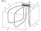
- FIG. 1 is a perspective view illustrating a state in which an air conditioner 100 according to an embodiment is installed in a room 10.
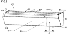
- FIG. It is a perspective view which shows the air conditioner 100 in embodiment.
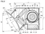
- FIG. 3 is a cross-sectional view taken along line III-III in FIG. 2.
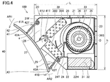
- FIG. 4 is a cross-sectional view taken along the line IV-IV in FIG. 2.
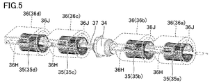
- It is a perspective view which shows one of the several multiblade centrifugal fans 35 with which the air blower 33 with which the air conditioner 100 in embodiment is provided is equipped.
- It is a top view which shows typically the air blower 33 and the heat exchanger 38 with which the air conditioner 100 in embodiment is equipped.
- FIG. 5 is a cross-sectional view corresponding to FIG. 3 and showing a state when the air conditioner 100 in the embodiment forms a state of cooling operation or air blowing operation.
- FIG. 5 is a perspective view which shows a mode when the air_conditioning
- FIG. It is a perspective view which shows a mode at the time of the air conditioner 100 in embodiment forming the state of heating operation.
- FIG. 4 is a cross-sectional view corresponding to FIG. 3 and showing a state when the air conditioner 100 in the embodiment forms a heating operation state. It is a perspective view which shows the mode at the time of heating operation being performed in the room 10 with the air conditioner 100 in embodiment. It is a perspective view which shows a part of air blower with which the air conditioner in Embodiment 6 is equipped.
- FIG. 10 is a plan view showing a blower provided in an air conditioner according to Embodiment 7.
- FIG. 7 It is a front view which shows some blowers (drive motor 34A, multiblade centrifugal fan 35, and casing 36 (36a, 36b)) with which the air conditioner in Embodiment 7 is equipped. It is a perspective view which shows the mode of the front and upper surface side of some air blowers with which the air conditioner in Embodiment 7 is equipped (drive motor 34A, the multiblade centrifugal fan 35, and the casing 36). It is a 1st perspective view which shows the mode of the back surface and upper surface side of some air blowers with which the air conditioner in Embodiment 7 is equipped (drive motor 34A, the multiblade centrifugal fan 35, and the casing 36).
- FIG. 20 is a plan view schematically showing a blower and heat exchangers 38M and 38N provided in an air conditioner according to Embodiment 8. It is a perspective view which shows the air conditioner 101 in Embodiment 9.
- FIG. 25 is a cross-sectional view taken along the line XXV-XXV in FIG. 24.
- FIG. 1 is a perspective view showing a state in which the air conditioner 100 is installed in a room 10.
- FIG. 2 is a perspective view showing the air conditioner 100.
- 3 is a cross-sectional view taken along line III-III in FIG. 2
- FIG. 4 is a cross-sectional view taken along line IV-IV in FIG.
- the air conditioner 100 is used as a so-called air conditioner.
- the back surface 23 (FIGS. 3 and 4) of the housing 20 is fixed to the side wall 12 using a metal fitting (not shown).
- the air conditioner 100 may be installed on the ceiling 11 by fixing the upper surface 21 of the casing 20 to the ceiling 11 of the room 10 using a metal fitting or the like.
- the air conditioner 100 includes a housing 20, an air filter 31, an air purifying filter 32, a blower 33, a heat exchanger 38, and a wind direction adjusting unit 40.
- the housing 20 has an upper surface 21 disposed so as to face the ceiling 11 of the room 10, a lower surface 22 positioned on the floor surface (see the floor surface 13 in FIG. 11), and the side wall 12 (FIGS. 1 and 11).
- a side wall 26 disposed on the other end side in the direction.
- the upper surface 21 of the housing 20 has a substantially plate shape, and the upper surface 21 side of the housing 20 is closed.
- the lower surface 22 of the housing 20 is located on the opposite side of the upper surface 21, and a suction port 22 ⁇ / b> H (FIGS. 3 and 4) is formed on the lower surface 22.
- the suction port 22 ⁇ / b> H extends in a substantially horizontal direction along the longitudinal direction of the housing 20.
- the back surface 23 is provided so as to connect between the rear end portion of the upper surface 21 and the rear end portion of the lower surface 22, and in a state where the air conditioner 100 is installed on the side wall 12, the back surface 23 is in the vertical direction. It becomes almost parallel.
- the front surface 24 is provided so as to stand in a substantially L shape from the front end portion of the lower surface 22. Between the front end portion 24T (FIGS. 3 and 4) of the front surface 24 and the front end portion 21F of the upper surface 21, a space for arranging the shaft support portions 41T, 42T, 43T, the heat exchanger 38, and the like is formed. .
- each of the shaft support portions 41T, 42T, and 43T has a shape extending in a rod shape.
- the shaft support portions 41T, 42T, and 43T all extend in a direction perpendicular to the paper surface of FIGS. 3 and 4, and both end portions of the shaft support portion 41T, both end portions of the shaft support portion 42T, and both ends of the shaft support portion 43T. All the parts are fixed by the side wall 25 and the side wall 26, respectively.
- a front upper opening 28 and a front lower opening 29 are formed in the space (opening 27) on the front side of the housing 20.
- Air filter 31 and air purifying filter 32 As shown in FIGS. 3 and 4, the air filter 31 and the air purification filter 32 are provided inside the housing 20.
- the air filter 31 is disposed above the suction port 22H so as to cover the suction port 22H.
- the air purification filter 32 is disposed above the air filter 31.
- the air cleaning filter 32 is composed of, for example, a HEPA filter.
- FIG. 3 is a perspective view showing the blower 33.
- the blower 33 includes a drive motor 34, a plurality of multiblade centrifugal fans 35 (35 a to 35 d), and a rotating shaft 37.
- the plurality of multi-blade centrifugal fans 35 are connected to the drive motor 34 via a rotating shaft 37, and are arranged side by side in the horizontal direction so as to be coaxial with the drive motor 34.
- a plurality of multi-blade centrifugal fans 35 are provided two each on one side and the other side in the axial direction of the drive motor 34.
- the multi-blade centrifugal fan 35 (35a, 35b) and the multi-blade centrifugal fan 35 (35c, 35d) are disposed at positions that are symmetrical with respect to the position of the drive motor 34.
- the drive motor 34 is disposed at a position near the center of the housing 20 in the horizontal direction (longitudinal direction of the housing 20), and the plurality of multi-blade centrifugal fans 35 (35a to 35d) are arranged more horizontally than the drive motor 34 in the horizontal direction. Is also arranged at the outer position.
- FIG. 6 is a perspective view showing one of a plurality of multiblade centrifugal fans 35 provided in the blower 33.
- the multiblade centrifugal fan 35 has frame bodies 35P and 35Q formed in an annular shape, a boss 35R erected at the center of the frame body 35Q, and a plurality of blade portions 35F.
- the frames 35P and 35Q are arranged at positions separated from each other in the axial direction.
- Each of the plurality of blade portions 35F is supported at both ends by frame bodies 35P and 35Q.
- the multiblade centrifugal fan 35 is connected to the rotating shaft 37 (FIG. 5) via a boss 35R.
- the multiblade centrifugal fan 35 sends the air taken in from the inner peripheral side to the outer peripheral side by a plurality of rotating blade portions 35F.
- the multiblade centrifugal fan 35 sends out air radially outward from the rotation center side of the fan by utilizing centrifugal force.
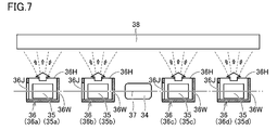
- FIG. 7 is a plan view schematically showing the blower 33 and the heat exchanger 38.
- the blower 33 of the present embodiment further includes a plurality of casings 36 (36a to 36d).
- Each of the plurality of casings 36 (36a to 36d) forms a spiral flow path 36S (FIGS. 3 and 4) on the inner side, and surrounds each of the plurality of multiblade centrifugal fans 35 (35a to 35d). It is arranged so as to cover.
- Each of the plurality of casings 36 (36a to 36d) has a side wall 36W, a through hole 36J, and an opening 36H.
- the side wall 36 ⁇ / b> W and the through hole 36 ⁇ / b> J are located on opposite sides of the multiblade centrifugal fan 35 in the direction of the rotation axis (rotation shaft 37) of the multiblade centrifugal fan 35.
- the opening 36H is formed on the front side of the casing 36, and the casing 36 is disposed such that the opening 36H opens toward the heat exchanger 38 side.
- each of the plurality of multi-blade centrifugal fans 35 (35a to 35d) is surrounded by each of the plurality of casings 36 (36a to 36d) as described above.
- a side wall 36 ⁇ / b> W of the casing 36 is located between the blade centrifugal fans 35.
- the air heated or cooled by the heat exchanger 38 passes through the outlets described later (the front upper outlet 28H shown in FIGS. 8 and 9 and the front lower outlet 29H shown in FIGS. 12 and 13). Will be blown out.
- the heat exchanger 38 includes an upper heat exchange part 38A and a lower heat exchange part 38B.
- Each of the upper heat exchanging portion 38A and the lower heat exchanging portion 38B includes a plurality of heat transfer tubes (tube materials) and a plurality of fins (plate materials) that support them.
- the upper heat exchanging portion 38A as a whole is arranged to be inclined so as to extend from the rear toward the front as it goes from the upper side to the lower side, and the lower heat exchanging portion 38B as a whole is located at the rear as it goes from the lower side to the upper side. It inclines so that it may extend toward the front from.
- the heat exchanger 38 has a substantially V-shaped shape as a whole, and is fixed by the housing 20 or the like so that the bent portion is located on the foremost side of the heat exchanger 38.
- the heat exchanger 38 is disposed so as to face the blower 33 from the front side, and can heat or cool the air from the blower 33.
- an opening 27 is formed between the front end portion 24T of the front surface 24 of the housing 20 and the front end portion 21F of the upper surface 21 of the housing 20.
- the shaft support portion 42T is disposed at a position near the front end portion 21F of the upper surface 21, and the shaft support portion 43T is disposed at a position immediately in front of the front end portion 24T of the front surface 24 (near the lower portion).
- the shaft support portion 41T is disposed at a position between the shaft support portion 41T and the shaft support portion 43T.
- a front upper opening 28 and a front lower opening 29 are formed on the front side of the housing 20.
- the front upper opening 28 is formed between the shaft support portion 41T and the shaft support portion 42T
- the front lower opening 29 is formed between the shaft support portion 41T and the shaft support portion 43T.
- the wind direction adjusting unit 40 is disposed so as to cover the opening 27 (here, the front upper opening 28 and the front lower opening 29) formed on the front side of the housing 20 from the front side.
- the wind direction adjusting unit 40 of the present embodiment includes a movable panel 41, an upper wind direction plate 42 and a lower wind direction plate 43.
- the movable panel 41, the upper wind direction plate 42, and the lower wind direction plate 43 all have a plate-like shape, and extend by substantially the same length as the length in the longitudinal direction (horizontal direction) of the housing 20. (FIGS. 1 and 2).
- the movable panel 41 has an upper end 41A and a lower end 41B, and a portion of the movable panel 41 between the upper end 41A and the lower end 41B is recessed toward the inner side of the housing 20 (the back surface 23 side). Further, it is formed in a curved concave shape.
- the height of the movable panel 41 (the distance between the upper end 41A and the lower end 41B) is set so that its height dimension is slightly larger than the height h of the housing 20.
- a support portion 41U having a plate shape is formed at a position between the upper end 41A and the lower end 41B of the movable panel 41 so as to protrude toward the back surface (back surface 23).
- FIG. 3 shows a cross-sectional shape at a substantially central position in the longitudinal direction (horizontal direction) of the movable panel 41
- FIG. 4 shows a cross-sectional shape at a position near the end in the longitudinal direction of the movable panel 41.
- the support portion 41U is provided at least at a substantially central position in the longitudinal direction of the movable panel 41 (see FIG. 3), and is connected to the shaft support portion 41T.
- the movable panel 41 is pivotally supported by the pivotal support portion 41T at a substantially central position in the vertical direction (height direction) of the housing 20.
- the movable panel 41 is not limited to such a position, and a plurality of support portions 41U may be provided so as to be arranged at intervals in the longitudinal direction of the movable panel 41.
- the movable panel 41 is pivotally supported through one or more pivotal support portions 41T so as to be swingable in the directions indicated by the arrows AR1 and AR2.
- the upper wind direction plate 42 is formed in a plate shape having a height dimension shorter than the height dimension of the movable panel 41.
- the upper wind direction plate 42 is connected to the shaft support portion 42T, and is supported by the shaft support portion 42T so as to be swingable.
- the lower wind direction plate 43 is also formed in a plate shape having a height dimension shorter than the height dimension of the movable panel 41.
- the lower wind direction plate 43 is connected to the shaft support portion 43T, and is rotatably supported via the shaft support portion 43T.
- FIGS. 2 to 4 show a state in which the air conditioner 100 is in a shutdown state.
- the air conditioner 100 transitions from the operation state to the operation stop state (that is, at the time of the operation stop)
- the movable panel 41 and the upper wind direction plate 42 rotate, whereby the rear surface and the upper wind direction of the movable panel 41 are rotated.
- the tip 42A of the plate 42 is close to each other.
- Each of the movable panel 41 and the upper wind direction plate 42 is arranged at a position that closes the front upper opening 28 by rotating in this way.
- each of the movable panel 41 and the lower wind direction plate 43 rotates, the back surface of the movable panel 41 and the tip 43A of the lower wind direction plate 43 come close to each other.
- Each of the movable panel 41 and the lower wind direction plate 43 is disposed at a position that closes the front lower opening 29 by rotating in this way.
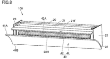
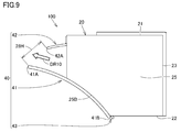
- FIGS. 8 and 9 are a perspective view and a side view, respectively, showing a state when the air conditioner 100 is in a cooling operation state or a blowing operation state.
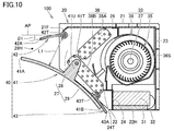
- FIG. 10 corresponds to FIG. 3, and is a cross-sectional view showing a state when the air conditioner 100 is in a cooling operation state or a blowing operation state.
- the movable panel 41 and the lower wind direction plate 43 are on the lower side.
- the rear surface of the movable panel 41 is close to the front end 25B (FIG. 9) on the lower side of the side wall 25, the front end (not shown) on the lower side of the side wall 26 having the same configuration, and the lower wind direction plate 43.
- the front lower opening 29 (FIG. 10) is closed.
- a front upper blowing portion 28 ⁇ / b> H is formed between the upper end 41 ⁇ / b> A of the movable panel 41 and the front end 42 ⁇ / b> A of the upper wind direction plate 42 (above the front of the housing 20).
- a lower front blowing portion 29H (FIGS. 13 and 14) described later is closed. In this state, the plurality of multiblade centrifugal fans 35 are rotated by the drive motor 34 (FIG. 5).
- the air is taken into the housing 20 through the suction port 22H, the air filter 31, and the air cleaning filter 32.
- the air passes through the heat exchanger 38 and the opening (the front upper opening 28), and the air direction is adjusted by the air direction adjusting unit 40 (here, the movable panel 41 and the upper air direction plate 42).
- the air is blown out through the front upper blowout portion 28H formed on the side (arrow DR10 shown in FIG. 9).
- the air blown from the front upper blowout portion 28 ⁇ / b> H travels along the ceiling 11 and then moves down along the side walls 14 to 16 facing the air conditioner 100.
- the air further travels along the floor surface 13 so as to return to the air conditioner 100.
- the air rises along the side wall 12 toward the suction port 22 ⁇ / b> H provided on the lower surface 22 of the air conditioner 100.
- the entire room 10 is cooled by such air flow.
- such a circulating airflow can be formed in the room 10, and an efficient cooling effect and blowing effect can be obtained.
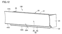
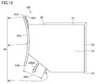
- FIGS. 12 and 13 are a perspective view and a side view, respectively, showing a state when the air conditioner 100 is in a heating operation state.
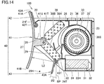
- FIG. 14 corresponds to FIG. 3 and is a cross-sectional view showing a state when the air conditioner 100 is in a heating operation state.
- the movable panel 41 and the upper wind direction plate 42 rotate upward.
- the rear surface of the movable panel 41 is close to the front end 25A (FIG. 13) on the upper side of the side wall 25, the front end (not shown) on the upper side of the side wall 26 having the same configuration, and the upper wind direction plate 42.
- the front upper opening 28 (FIG. 14) is closed.
- the air is taken into the housing 20 through the suction port 22H, the air filter 31, and the air cleaning filter 32.
- the air passes through the heat exchanger 38 and the opening (the front lower opening 29), and the air direction is adjusted by the air direction adjusting unit 40 (here, the movable panel 41 and the lower air direction plate 43).
- the air is blown out through the front lower blowing portion 29H formed on the side (arrow DR20 shown in FIG. 13).
- the air blown out from the front lower blowing portion 29 ⁇ / b> H descends along the side wall 12 and then advances along the floor surface 13. The air further moves up along the side walls 14-16.
- the whole room 10 is warmed by such a flow of air.
- the air conditioner 100 such an air flow can be formed in the room 10, and an efficient heating effect can be obtained.
- the suction port 22 ⁇ / b> H is formed in the lower surface 22 of the housing 20, and the air taken in from the suction port 22 ⁇ / b> H passes through the air filter 31 and the air purification filter 32. Therefore, it is possible to perform air conditioning with less energy consumption while always performing air cleaning.
- the movable panel 41 is pivotally supported by the pivotal support portion 41T at a substantially central position in the horizontal direction and the (vertical direction) height direction of the casing 20.
- the movable panel 41 can form an upper and lower double opening air outlet at the front upper side and the front lower side of the housing 20, for example, without switching the upper and lower shafts or a complicated mechanism such as a lock mechanism. Even if a structure is not used, it is possible to realize opening and closing of the upper and lower double opening type air outlets with a simple structure.
- the shortest distance from the back surface of the movable panel 41 to the upper end portion of the front upper opening 28 (here, the position of the shaft support portion 42T) when the operation is stopped is defined as a. Further, the shortest distance from the back surface of the movable panel 41 to the lower end portion of the front lower opening 29 (here, the position of the shaft support portion 43T) when the operation is stopped is defined as b.
- the shortest distance from the back surface from the movable panel 41 during cooling operation to the upper end portion of the front upper opening 28 is L1.
- the shortest distance from the back surface of the movable panel 41 during heating operation to the lower end portion of the front lower opening 29 is L2.
- the upper wind direction plate 42 is pivotally supported at the position of the upper end portion of the front upper opening 28, and the upper wind direction plate 42 is pivotally supported during the cooling operation.
- the front upper opening 28 is opened by rotating upward about the portion (the shaft support portion 42T), and a straight line connecting the shaft support portion 42T and the tip 42A of the upper wind direction plate 42 is forward with respect to the horizontal direction AP. It is good to arrange
- lower wind direction plate 43 is pivotally supported at the lower end portion of front lower opening 29, and lower wind direction plate 43 is pivotally supported during heating operation.
- the front lower opening 29 is opened by rotating downward about the portion (the shaft support portion 43T), and a straight line connecting the shaft support portion 43T and the tip 43A of the lower wind direction plate 43 is forward with respect to the vertical direction BP. It is good to arrange so that it may become angle theta below 45 degrees below. According to the said structure, a more suitable airflow can be sent out from the front lower blowing part 29H at the time of heating. For example, it is possible to suppress that warm air hardly reaches the floor surface due to buoyancy, and an efficient heating effect can be obtained.
- the lower wind direction plate 43 may be configured so that the short circuit phenomenon in which the air blown through the front lower opening 29 is immediately sucked into the suction port 22H during the heating operation is suppressed by the lower wind direction plate 43. . It becomes possible to send out a more suitable air flow during heating, and it is possible to suppress the temperature of the housing 20 from rising unnecessarily, and it is possible to further improve energy saving.
- FIG. 16 corresponds to FIG. 5 in the above-described embodiment, and is a perspective view showing a blower provided in the air conditioner in the sixth embodiment.
- four multi-blade centrifugal fans 35 35a to 35d are driven by one drive motor.
- two multi-blade centrifugal fans 35 are connected to one drive motor 34A via a rotating shaft 37A, and are coaxial with the drive motor 34A. Are arranged side by side in the horizontal direction. Two multi-blade centrifugal fans 35 (35a, 35b) are driven by one drive motor 34A.
- two multi-blade centrifugal fans 35 are connected to one drive motor 34B via a rotating shaft 37B and arranged side by side in the horizontal direction so as to be coaxial with the drive motor 34B. Yes. Two multi-blade centrifugal fans 35 (35c, 35d) are driven by one drive motor 34B.
- the plurality of multiblade centrifugal fans 35 (35a to 35d) and the drive motors 34A and 34B are arranged side by side in the horizontal direction so as to be coaxial.
- the drive motors 34A and 34B are disposed at positions near the center of the housing 20 in the horizontal direction (longitudinal direction of the housing 20), and are adjacent to each other.
- the multiblade centrifugal fan 35 (35a, 35b) is arranged at a position outside the drive motor 34A in the horizontal direction, and the multiblade centrifugal fan 35 (35c, 35d) is outside the drive motor 34B in the horizontal direction. It is arranged at the position.
- FIG. 17 is a plan view showing a blower provided in the air conditioner according to the seventh embodiment.
- FIG. 18 is a front view showing a part of the blower (drive motor 34A, multiblade centrifugal fan 35 and casing 36 (36a, 36b)) provided in the air conditioner according to the seventh embodiment.
- the present embodiment is different from the above-described other embodiments in the configuration of the casing 36 provided in the blower.
- Each of the plurality of casings 36 forms a spiral channel 36S (FIGS. 3 and 4) on the inner side, and surrounds each of the plurality of multiblade centrifugal fans 35 (35a to 35d).
- This embodiment is common to the above-described embodiments (see FIG. 17).
- the present embodiment and the above-described embodiments are also common in that each of the plurality of casings 36 (36a to 36d) is disposed so as to open toward the heat exchanger 38 side. (See FIG. 22).
- a frame portion 36F and a plurality of guide fins 36T are provided on the heat exchanger 38 side in each of the casings 36 (36a to 36d).
- a through hole 36Y (FIG. 20) is provided on one side in the axial direction of the blade centrifugal fan 35, and a through hole 36J (FIG. 21) is provided on the other side in the axial direction of the multiblade centrifugal fan 35.
- the through hole 36Y and the through hole 36J are located on opposite sides of the multiblade centrifugal fan 35 in the direction of the rotation axis of the multiblade centrifugal fan 35 (FIG. 22).
- the frame portion 36F is formed in a square frame shape, and has a shape extending outward in a flange shape on the front side of the casing 36 (FIGS. 18 and 19).
- the shape of the inner peripheral surface of the frame portion 36F is such that the flow path cross-sectional area of the opening 36H formed on the downstream side (front side) of the multiblade centrifugal fan 35 gradually increases from the upstream side toward the downstream side. Is formed.
- the plurality of guide fins 36T are arranged side by side with an interval inside the frame portion 36F so as to extend along a direction perpendicular to the rotation shaft (rotation shafts 37A, 37B) of the multiblade centrifugal fan 35. Yes.
- a total of five guide fins 36T are arranged inside the frame portion 36F.
- the guide fin 36T located at the center of the five sheets has a flat plate shape.
- the two guide fins 36T located on both outer sides of the flat guide fins 36T are formed to bend outward as they go from the upstream side to the downstream side.
- the two guide fins 36T located on both outer sides are also formed to bend outward as they go from the upstream side to the downstream side.
- the guide fins 36T arranged on the outer side are formed so as to bend toward the outside more steeply than the guide fins 36T arranged on the inner side.
- FIG. 23 is a plan view schematically showing a blower and heat exchangers 38M and 38N provided in the air conditioner according to the eighth embodiment. This embodiment is different from the above-described embodiments in the following points.
- the air conditioner of the present embodiment includes heat exchangers 38M and 38N, and the blower disposed so as to be opposed to the heat exchangers 38M and 38N includes drive motors 34A and 34B and a plurality of multiblade centrifugal fans 35 (35a to 35d). ), And a plurality of casings 36 (36a to 36d).
- the heat exchanger 38M includes a plurality of fins 39F (plate material) and heat transfer tubes 39H (tube materials). Each of the plurality of fins 39F has a flat plate shape and is arranged in a direction parallel to the rotation center of the multiblade centrifugal fan 35 (35a, 35b) so as to have a parallel positional relationship. ing.
- the heat transfer tube 39H includes a plurality of straight portions 39S and a plurality of curved portions 39W.
- the plurality of linear portions 39S are attached to the plurality of fins 39F, extend along a direction parallel to the rotation center of the multiblade centrifugal fan 35 (35a, 35b), and have a parallel positional relationship.
- the heat exchanger 38N also has a plurality of fins 39F (plate material) and heat transfer tubes 39H (tube materials).
- Each of the plurality of fins 39F has a flat plate shape and is arranged in a direction parallel to the rotation center of the multiblade centrifugal fan 35 (35c, 35d) so as to have a parallel positional relationship.
- the heat transfer tube 39H includes a plurality of straight portions 39S and a plurality of curved portions 39W.
- the plurality of linear portions 39S are attached to the plurality of fins 39F, extend along a direction parallel to the rotation center of the multiblade centrifugal fan 35 (35c, 35d), and have a parallel positional relationship.
- the plurality of curved portions 39W are provided on both outer sides of the plurality of linear portions 39S so as to connect the ends of two adjacent linear portions 39S.
- the length of the region of the heat exchanger 38N where the linear portion 39S is provided is defined as Z2.
- the multi-blade centrifugal fan 35 (35a, 35b) is connected to the drive motor 34A via a rotation shaft 37A, and is arranged in the horizontal direction so as to be coaxial with the drive motor 34A.
- the multi-blade centrifugal fan 35 (35c, 35d) is connected to the drive motor 34B via a rotation shaft 37B, and is arranged side by side in the horizontal direction so as to be coaxial with the drive motor 34B.
- Each of the casings 36 (36a, 36b) forms a spiral flow path inside, and each covers the periphery of each of the plurality of multi-blade centrifugal fans 35 (35a, 35b), and on the heat exchanger 38M side. It arrange
- a frame portion 36F that forms a ventilation path on the inside and at least one guide fin 36T are provided.
- Each of the casings 36 (36c, 36d) forms a spiral flow path inside, and each covers the periphery of each of the plurality of multiblade centrifugal fans 35 (35c, 35d), and on the heat exchanger 38M side. It arrange
- a frame portion 36F that forms an air passage inside and at least one guide fin 36T are provided on the side of the heat exchanger 38N in each of the casings 36 (36c, 36d).
- At least one guide fin 36T (five in the present embodiment) has a blowing path formed inside the frame 36F in a direction perpendicular to the rotation center of the multiblade centrifugal fan 35 (35c, 35d). It is arranged to divide.
- each of the casings 36 (36c, 36d)
- a plurality of air paths formed by dividing the air flow path by at least one guide fin 36T on the side of the heat exchanger 38N.
- Each of the openings 36H is parallel to the rotation center of the plurality of multi-blade centrifugal fans 35 (35c, 35d) from the side of the plurality of multi-blade centrifugal fans 35 (35c, 35d) toward the heat exchanger 38N. It is formed so that the width in any direction gradually increases.
- the frame portion 36F provided in the casing 36 (36a) has an inner peripheral surface 36U that forms an air blowing path inside.
- the inner peripheral surface 36U includes a first outlet region 36U1 and a second outlet region 36U2.
- region 36U1 is a part which overlaps with the guide fin 36T in the one side of the direction parallel to the rotation center of the multiblade centrifugal fan 35 (35a) among the internal peripheral surfaces 36U. This portion is defined as the first outlet region 36U1.
- the first outlet region 36U1 is , A part of the inner peripheral surface 36U, which overlaps the projected images of the plurality of guide fins 36T formed by this projection.
- the second outlet region 36U2 is a portion overlapping the guide fins 36T on the other side of the inner peripheral surface 36U in the direction parallel to the rotation center of the multiblade centrifugal fan 35 (35a). This portion is defined as the second outlet region 36U2.
- the second exit area 36U2 when the plurality of guide fins 36T provided in the casing 36 (36a) are projected toward the other side in the parallel direction (here, the left side in FIG. 23), the second exit area 36U2 , A part of the inner peripheral surface 36U, which overlaps the projected images of the plurality of guide fins 36T formed by this projection.
- the most upstream part of the first outlet region 36U1 and the most upstream part of the second outlet region 36U2 Is defined.
- An interval between these portions in a direction parallel to the rotation center of the multiblade centrifugal fan 35 (35a) is defined as a width w (w1).
- the portion located on the most downstream side in the first outlet region 36U1 and the portion located on the most downstream side in the second outlet region 36U2 Is defined.
- An interval between these portions in a direction parallel to the rotation center of the multiblade centrifugal fan 35 (35a) is defined as a width y (y1).
- the width w (w2, w3, w4) is defined for each of the casings 36 (36b, 36c, 36d) in exactly the same manner as the case of the width w (w1) of the casing 36 (36a). In the same manner as the case of the width y (y1) of the casing 36 (36a), the width y (y2, y3, y4) is defined for each of the casings 36 (36b, 36c, 36d).
- W w1 + w2 + w3 + w4.
- Z Z1 + Z2.
- Patent Document 9 Japanese Unexamined Patent Publication No. 2013-104592 described at the beginning discloses the configuration of an air conditioner having a plurality of multiblade centrifugal fans.
- the partition plate and the frame are arranged between the blower chamber and the heat exchanger chamber, and it is necessary to provide a long distance between the downstream of the fan casing and the heat exchanger, and the entire air conditioner There is a possibility that the size will increase.
- the blower When the blower is configured using a plurality of multiblade centrifugal fans, for example, in the direction parallel to the rotation center of the plurality of multiblade centrifugal fans, It can be set to be smaller than the width. If the distance between the multi-blade centrifugal fan and the heat exchanger is too close, the air exhausted from the fan will flow to the heat exchanger where the fan faces, but the heat exchanger where the fan does not face It hardly circulates in the place, and when viewed as a whole of the heat exchanger, the air volume and the wind speed vary depending on the place where it circulates. For this reason, it may be difficult to sufficiently improve the efficiency of the air conditioner.
- the configuration described in the above-described eighth embodiment can be implemented in combination with the configuration described in the above-described first to seventh embodiments, or the configuration described in the above-described first to seventh embodiments. It is also possible to carry out independently.
- the wind direction adjusting unit having the configuration described in the first to seventh embodiments is not essential.
- the suction port 22H (see FIGS. 2 and 3) may not be formed on the lower surface 22 side, and the suction port 22H may be formed on the upper surface 21 and / or the side walls 25 and 26 side.
- the air outlet is not limited to the configuration shown in the front upper air outlet 28H (FIG. 9) and the front lower air outlet 29H (FIG. 13), and the air outlet may be formed on the lower surface 22 side. Alternatively, it may be formed on the side walls 25 and 26 side.
- an air filter When providing a suction port in the side wall 25, an air filter may be disposed so as to cover the suction port of the side wall 25 from the inside of the housing 20, and an air purifying filter may be disposed inside the air filter.
- an air filter When providing a suction port on the side wall 26, an air filter may be disposed so as to cover the suction port of the side wall 26 from the inside of the housing 20, and an air purifying filter may be disposed inside the air filter.
- the air filter 31 may not be disposed above the suction port 22H. As long as the air filter 31 is disposed so as to cover the suction port 22H from the inner side of the housing 20, for example, the air filter 31 may be disposed below or on the side of the suction port 22H. Similarly, the air purification filter 32 may not be disposed above the air filter 31. As long as the air purification filter 32 is disposed so as to cover the air filter 31 from the inside of the housing 20, for example, the air purification filter 32 may be disposed below or on the side of the air filter 31. If the air blower 33 is arrange
- an air conditioner employing the configuration of the modification of the eighth embodiment can perform air conditioning with less energy consumption while always performing air cleaning, and can be reduced in size as compared with the prior art. It is possible.
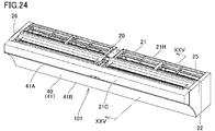
- FIG. 24 is a perspective view showing the air conditioner 101 according to the ninth embodiment.
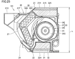
- FIG. 25 is a cross-sectional view taken along line XXV-XXV in FIG.
- the wind direction adjusting unit 40 (see FIGS. 1 and 2) is not shown in FIG. This embodiment differs from the above-described embodiments in the following points.
- the upper surface 21 side of the housing 20 is closed, and a suction port 22H (FIGS. 3 and 4) is formed on the lower surface 22 of the housing 20.
- the upper surface 21 side of the housing 20 is not closed, and the suction port 21 ⁇ / b> H is formed in the upper surface 21.
- the suction port 21 ⁇ / b> H is provided in a portion of the upper surface 21 near the back surface 23.
- a suction port 22 ⁇ / b> H (FIG. 25) is also formed on the lower surface 22 of the housing 20.
- a front cover 21 ⁇ / b> C extending in the horizontal direction is provided at a position further forward of the front end 21 ⁇ / b> F of the upper surface 21.
- an air filter 31A and an air purification filter 32A are further provided inside the housing 20.
- the air filter 31A is disposed so as to close the suction port 21H from the inside of the housing 20 below the suction port 21H provided on the upper surface 21 side, and the air purification filter 32A covers the air filter 31A from the lower side. Is arranged.
- the air cleaning filter 32A is also composed of, for example, a HEPA filter.
- air conditioner 101 of the present embodiment not only air is taken into the housing 20 through the suction port 22H (FIG. 25), the air filter 31 (FIG. 25), and the air cleaning filter 32 (FIG. 25). Air is taken into the housing 20 through the suction port 21H, the air filter 31A, and the air purification filter 32A.
- the air then passes through the heat exchanger 38 and the opening 27 (the front upper opening 28 or the front lower opening 29), and is formed on the front surface 24 side in a state where the wind direction is adjusted by the wind direction adjusting unit 40 (FIG. 24).
- the air is blown out of the machine through the air outlet (that is, the front upper air outlet 28H shown in FIG. 10 or the front lower air outlet 29H shown in FIG. 14).
- the air volume can be increased as compared with the air conditioners in the first to eighth embodiments.
- the technical idea of providing the suction port 21H on the upper surface 21 side without closing the upper surface 21 side can be implemented in combination with the ideas described in the above first to eighth embodiments.
Landscapes
- Engineering & Computer Science (AREA)
- Chemical & Material Sciences (AREA)
- Combustion & Propulsion (AREA)
- Mechanical Engineering (AREA)
- General Engineering & Computer Science (AREA)
- Air-Conditioning Room Units, And Self-Contained Units In General (AREA)
- Air Filters, Heat-Exchange Apparatuses, And Housings Of Air-Conditioning Units (AREA)
Abstract
部屋の側壁上部または天井に設置される空気調和機(100)であって、上面(21)および下面(22)を有し、下面側に吸込口(22H)が形成され、前面側に開口(27)が形成された筺体(20)と、吸込口(22H)覆うように配置されたエアフィルター(31)と、エアフィルターの上方に配置された空気清浄フィルター(32)と、送風機(33)と、熱交換器(38)と、開口(27)を前方側から覆うように配置された風向調整部(40)とを備える。送風機(33)は、駆動モーターに連結され、駆動モーターと同軸状となるように水平方向に並んで配置された複数の多翼遠心ファン(35)を含む。空気清浄を常に行ないながらより少ない消費エネルギーで空気調和を行なう、より小型化された空気調和機が得られる。
Description
本明細書は、部屋の側壁上部または天井に設置される空気調和機に関する。本出願は、2017年4月10日に出願した日本特許出願である特願2017-77718号に基づく優先権、および、2017年7月20日に出願した日本特許出願である特願2017-140996号に基づく優先権を主張する。当該日本特許出願に記載された全ての記載内容は、参照によって本明細書に援用される。
下記特許文献1~9は、空気調和機(いわゆるエアコン)に関する技術を開示している。最近は、より一層少ないエネルギーで運転可能な空気調和機が求められている。空気調和機は一般的に、空気清浄フィルターを備えている。空気清浄フィルターの存在は、圧力損失(圧損)を招く。省エネルギーの観点では、空気清浄フィルターの圧損は極力小さいことが望ましい。しかしながら、圧損を小さくすると空気清浄フィルターの空気清浄能力が低下しやすくなる。
そのような実情がある一方で、最近の住宅事情を考慮すると、より高い空気清浄能力を有する空気調和機が求められる。すなわち、高気密化および高断熱化された住宅が増加しており、室内の空気が外気と入れ替わる機会が従来に比べて少なくなってきている。空気調和(暖房、冷房、除湿など)を行ないつつ、十分な空気清浄を併せて行なうことが可能な空気調和機によれば、このような状況であっても高い利便性を発揮することができる。
最近は従来に比べて狭い居室も増加してきているため、特に、部屋の側壁上部や天井に設置される空気調和機において、より少ない消費エネルギーで空気調和を行ないつつ高い空気清浄能力を実現することができれば、そのような空気調和機はより高い利便性を発揮することができる。
従来の空気調和機に高い空気清浄能力を有する空気清浄フィルターを搭載すると、そのような空気清浄フィルターが招く圧損のために、風量が低下してしまい、空気調和機としての省エネルギー性が低くなる。上記の特許文献1に記載された空気調和機においては、前方吹出口と両コーナー吹出口との計3方向から空気を吹き出すことが可能なターボファンが、筺体の内部に送風機として配置されている。
このターボファンは、その回転軸が鉛直方向に対して平行となるように配置されている。このようなターボファンは、空気清浄フィルターが招く圧損に打ち勝つことが可能であるが、空気調和機の奥行き寸法が大きくなり、結果として空気調和機の大型化を招きやすい。空気調和機による圧迫感が大きくなってしまい、室内環境や美観向上などにも制限をもたらすこととなる。
上記の特許文献2~4に開示された空気調和機においては、可動式の空気清浄フィルターが採用されていたり、メインの吸込口とは別の吸込口を設けることで空気清浄フィルターを介さずに空気を吸込み可能なように構成されていたりする。当該構成は、空気清浄フィルターを通過しない送風経路を設けることで、圧損を生じないようにして空気調和を行なうというものであるが、当該構成ではそもそも空気清浄を行なうことができない。
本明細書は、空気清浄を常に行ないながらより少ない消費エネルギーで空気調和を行なうことができるとともに、従来に比して小型化を図ることが可能な空気調和機を開示することを目的とする。
本明細書に開示される空気調和機は、部屋の側壁上部または天井に設置される空気調和機であって、上記天井に面するように配置される上面と、床面側に位置する下面と、上記側壁側に配置される背面と、を有し、上記下面側に吸込口が形成され、上記背面とは反対側である前面側に開口が形成された筺体と、上記吸込口の上方において上記吸込口を覆うように配置されたエアフィルターと、上記エアフィルターの上方に配置された空気清浄フィルターと、上記空気清浄フィルターの上方に配置された送風機と、上記送風機の前方または前方上方に配置された熱交換器と、上記開口を前方側から覆うように配置された風向調整部と、を備え、上記送風機は、駆動モーターと、上記駆動モーターに回転軸を介して連結され、上記駆動モーターと同軸状となるように水平方向に並んで配置された複数の多翼遠心ファンと、を含み、上記駆動モーターによって複数の上記多翼遠心ファンが回転することにより、上記吸込口、上記エアフィルターおよび上記空気清浄フィルターを通して上記筺体の内部に空気が取りこまれるとともに、空気は上記熱交換器および上記開口を通過して上記風向調整部によって風向きを調整された状態で、上記風向調整部の上部側または下部側に形成されている吹出口を通して機外に吹き出される。
上記空気調和機において、上記駆動モーターは、水平方向において上記筺体の中央寄りの位置に配置され、複数の上記多翼遠心ファンは、水平方向において上記駆動モーターよりも外側の位置に配置されていてもよい。
上記空気調和機において、上記多翼遠心ファンの直径をD[mm]とし、上記筺体の高さをh[mm]とすると、0.9×h≦2×D≦1.1×hの関係が成立していてもよい。
上記空気調和機において、上記筺体の奥行きをL[mm]とすると、0.9×L≦h+1/2×D≦1.1×Lの関係が成立していてもよい。
上記空気調和機において、上記送風機は、複数のケーシングをさらに有し、複数の上記ケーシングの各々は、螺旋形状の流路を内側に形成し、複数の上記多翼遠心ファンの各々の周囲を覆うとともに、上記熱交換器側に向けて開口するように配置されており、複数の上記ケーシングの各々における上記熱交換器側には、複数の上記多翼遠心ファンの各々と上記熱交換器との間に形成される送風経路を、上記多翼遠心ファンの回転軸に対して垂直な方向に分割する、1つまたは複数のガイドフィンが設けられていてもよい。
上記空気調和機において、冷房運転時または送風運転時には、上記風向調整部によって上記筺体の前方上方に上記吹出口が形成され、当該吹出口を通して空気が吹き出されてもよい。
上記空気調和機において、暖房運転時には、上記風向調整部によって上記筺体の前方下方に上記吹出口が形成され、当該吹出口を通して空気が吹き出されてもよい。
上記空気調和機において、上記吹出口は、上記筺体の前方上方に形成され、上記風向調整部により開閉される前方上方吹出部と、上記筺体の前方下方に形成され、上記風向調整部により開閉される前方下方吹出部と、を含み、冷房運転または送風運転が行なわれる際には、上記風向調整部によって上記前方上方吹出部が開放されるとともに上記前方下方吹出部は閉塞され、暖房運転が行なわれる際には、上記風向調整部によって上記前方上方吹出部が閉塞されるとともに上記前方下方吹出部は開放されてもよい。
上記空気調和機において、上記風向調整部は、板状の形状を有し上記開口を前面側から覆うように配置される可動パネルを含み、上記可動パネルは、上記筺体の上下方向における略中央の位置で軸支されており、上記可動パネルは、冷房運転または送風運転が行なわれる際には下方側に回動して上記前方上方吹出部を開放するとともに上記前方下方吹出部を閉塞し、暖房運転が行なわれる際には上方側に回動して上記前方上方吹出部を閉塞するとともに上記前方下方吹出部を開放してもよい。
上記空気調和機において、上記空気清浄フィルターは、HEPAフィルターから構成されていてもよい。
本明細書に開示される他の空気調和機は、部屋の側壁上部または天井に設置される空気調和機であって、上記天井に面するように配置される上面と、床面側に位置する下面と、上記側壁側に配置される背面と、上記背面とは反対側に配置される前面と、を有し、上記部屋の空気を自身の内部に取り込むための吸込口と、上記内部で調和された空気を上記部屋の中に送り出すための吹出口と、が形成された筺体と、上記筺体の上記内部の側から上記吸込口を覆うように配置されたエアフィルターと、上記筺体の上記内部の側から上記エアフィルターを覆うように配置された空気清浄フィルターと、上記筺体の上記内部に配置された送風機と、上記送風機の前方または前方上方に配置された熱交換器と、を備え、上記送風機は、駆動モーターと、上記駆動モーターに回転軸を介して連結され、上記駆動モーターと同軸状となるように水平方向に並んで配置された複数の多翼遠心ファンと、各々が螺旋形状の流路を内側に形成し、各々が複数の上記多翼遠心ファンの各々の周囲を覆うとともに上記熱交換器側に向けて開口するように配置された複数のケーシングと、を有し、複数の上記ケーシングの各々における上記熱交換器の側には、内側に送風経路を形成する枠部と、上記枠部の内側に形成された上記送風経路を、上記多翼遠心ファンの回転中心に対して垂直な方向に分割する、少なくとも1つのガイドフィンと、が設けられている。
上記空気調和機において、複数の上記ケーシングの各々について、上記熱交換器の側で上記ガイドフィンによって上記送風経路が分割されることで形成された複数の開口の各々は、上記多翼遠心ファンの側から上記熱交換器の側に向かうにつれて、上記回転中心に対して平行な方向における幅が徐々に拡大するように形成されていてもよい。
上記空気調和機において、上記熱交換器は、平板状の形状を有し、互いに平行な位置関係となるように上記平行な方向に並べられた複数のフィンと、複数の上記フィンに取り付けられ、上記平行な方向に沿って延在し、互いに平行な位置関係となるように配置された複数の直線部と、複数の上記直線部の両外側において2つの上記直線部の端部同士を接続するように設けられた複数の湾曲部とを含む、伝熱管と、を有し、複数の上記ケーシングの各々に設けられた上記枠部は、上記送風経路を内側に形成する内周面を有し、上記内周面のうち、上記平行な方向の一方側において上記ガイドフィンに重なる部分を第1出口領域と規定し、上記平行な方向の他方側において上記ガイドフィンに重なる部分を第2出口領域と規定し、上記第1出口領域のうちの最も上流側に位置する部分と上記第2出口領域のうちの最も上流側に位置する部分との間の上記平行な方向における間隔をwとし、上記第1出口領域のうちの最も下流側に位置する部分と上記第2出口領域のうちの最も下流側に位置する部分との間の上記平行な方向における間隔をyとし、複数の上記ケーシングの各々におけるwの値を、複数の上記ケーシングのすべてについて合計した値をWとし、上記平行な方向において、上記熱交換器のうちの上記直線部が設けられている領域の長さをZとした場合には、複数のうちの少なくとも1つの上記ケーシングにおいて、0.7×W/Z≦w/y≦1.3×W/Zの関係が成立していてもよい。
上記空気調和機において、上記多翼遠心ファンの直径をD[mm]とし、上記筺体の高さをh[mm]とすると、0.9×h≦2×D≦1.1×hの関係が成立していてもよい。
上記空気調和機において、上記空気清浄フィルターは、HEPAフィルターから構成されていてもよい。
上記の空気調和機によれば、空気清浄を常に行ないながらより少ない消費エネルギーで空気調和を行なうことができるとともに、奥行き寸法を小さくすることで従来に比して小型化を図ることが可能であり、圧迫感が小さくなり、室内環境や美観向上などへの制限を軽減することができる。
実施の形態について、以下、図面を参照しながら説明する。同一の部品および相当部品には同一の参照番号を付し、重複する説明は繰り返さない場合がある。
[実施の形態1]
図1~図7を参照して、実施の形態における空気調和機100の構成について説明する。空気調和機100の動作については、図8~図15を参照して後述する。図1は、空気調和機100が部屋10の中に設置されている様子を示す斜視図である。図2は、空気調和機100を示す斜視図である。図3は、図2中のIII-III線に沿った矢視断面図であり、図4は、図2中のIV-IV線に沿った矢視断面図である。
図1~図7を参照して、実施の形態における空気調和機100の構成について説明する。空気調和機100の動作については、図8~図15を参照して後述する。図1は、空気調和機100が部屋10の中に設置されている様子を示す斜視図である。図2は、空気調和機100を示す斜視図である。図3は、図2中のIII-III線に沿った矢視断面図であり、図4は、図2中のIV-IV線に沿った矢視断面図である。
図1および図2に示すように、空気調和機100は、いわゆるエアコン(Air Conditioner)として用いられる。本実施の形態の空気調和機100は、図示しない金具などを利用して、筺体20の背面23(図3,図4)が側壁12に固定される。このような固定構造に限られず、金具などを利用して筺体20の上面21が部屋10の天井11に固定されることで、空気調和機100は天井11に設置されてもよい。
図3,図4に示すように、空気調和機100は、筺体20、エアフィルター31、空気清浄フィルター32、送風機33、熱交換器38、および風向調整部40を備える。
(筺体20)
筺体20は、部屋10の天井11に面するように配置される上面21と、床面(図11における床面13を参照)側に位置する下面22と、側壁12(図1,図11)側に配置される背面23と、背面23とは反対側(すなわち筺体20の正面側)に位置する前面24と、筺体20の長手方向における一端側に配置される側壁25と、筺体20の長手方向における他端側に配置される側壁26と、を有する。
筺体20は、部屋10の天井11に面するように配置される上面21と、床面(図11における床面13を参照)側に位置する下面22と、側壁12(図1,図11)側に配置される背面23と、背面23とは反対側(すなわち筺体20の正面側)に位置する前面24と、筺体20の長手方向における一端側に配置される側壁25と、筺体20の長手方向における他端側に配置される側壁26と、を有する。
筺体20の上面21は、略板状の形状を有しており、筺体20の上面21側は閉塞されている。筺体20の下面22は、上面21の反対側に位置しており、下面22には吸込口22H(図3,図4)が形成されている。吸込口22Hは、筺体20の長手方向に沿うように、略水平な方向に延在している。
背面23は、上面21の後端部と下面22の後端部との間を接続するように設けられ、空気調和機100が側壁12に設置された状態では、背面23は鉛直方向に対して略平行となる。前面24は、下面22の前端部から略L字状に起立するように設けられている。前面24の前端部24T(図3,図4)と上面21の前端部21Fとの間には、軸支部41T,42T,43Tおよび熱交換器38などを配置するための空間が形成されている。
詳細は後述するが、軸支部41T,42T,43Tは、いずれも棒状に延びる形状を有している。軸支部41T,42T,43Tは、いずれも図3,図4の紙面に対して垂直な方向に延在しており、軸支部41Tの両端部、軸支部42Tの両端部、軸支部43Tの両端部は、いずれも側壁25および側壁26によってそれぞれ固定されている。
前面24の前端部24Tと上面21の前端部21Fとの間に上記のような軸支部41T,42T,43Tが配置されていることによって、前面24の前端部24Tと上面21の前端部21Fとの間の空間が区画され、筺体20の前面側の空間(開口27)には、前側上部開口28と前側下部開口29とが形成されている。
(エアフィルター31および空気清浄フィルター32)
図3,図4に示すように、エアフィルター31および空気清浄フィルター32は、筺体20の内部に設けられる。エアフィルター31は、吸込口22Hの上方において吸込口22Hを覆うように配置されている。空気清浄フィルター32は、エアフィルター31の上方に配置されている。空気清浄フィルター32は、たとえばHEPAフィルターから構成されている。
図3,図4に示すように、エアフィルター31および空気清浄フィルター32は、筺体20の内部に設けられる。エアフィルター31は、吸込口22Hの上方において吸込口22Hを覆うように配置されている。空気清浄フィルター32は、エアフィルター31の上方に配置されている。空気清浄フィルター32は、たとえばHEPAフィルターから構成されている。
(送風機33および熱交換器38)
図3,図4に示すように、送風機33は、空気清浄フィルター32の上方に配置され、熱交換器38は、送風機33の前方に配置される。このような構成に限られず、熱交換器38は、送風機33の前方上方に配置されていてもよい。図5は、送風機33を示す斜視図である。図3~図5に示すように、送風機33は、駆動モーター34と、複数の多翼遠心ファン35(35a~35d)と、回転軸37とを含む。
図3,図4に示すように、送風機33は、空気清浄フィルター32の上方に配置され、熱交換器38は、送風機33の前方に配置される。このような構成に限られず、熱交換器38は、送風機33の前方上方に配置されていてもよい。図5は、送風機33を示す斜視図である。図3~図5に示すように、送風機33は、駆動モーター34と、複数の多翼遠心ファン35(35a~35d)と、回転軸37とを含む。
複数の多翼遠心ファン35(35a~35d)は、駆動モーター34に回転軸37を介して連結されており、駆動モーター34と同軸状となるように、水平方向に並んで配置されている。本実施の形態では、複数の多翼遠心ファン35(35a~35d)は、駆動モーター34の軸方向における一方側および他方側の双方に、2つずつ設けられている。多翼遠心ファン35(35a,35b)および多翼遠心ファン35(35c,35d)は、駆動モーター34の位置を中心として左右対称となる位置に配置されている。換言すると、駆動モーター34は、水平方向(筺体20の長手方向)において筺体20の中央寄りの位置に配置され、複数の多翼遠心ファン35(35a~35d)は、水平方向において駆動モーター34よりも外側の位置に配置されている。
図6は、送風機33に備えられる複数の多翼遠心ファン35のうちの1つを示す斜視図である。多翼遠心ファン35は、環状に形成された枠体35P,35Qと、枠体35Qの中央部に立設されたボス35Rと、複数の羽根部35Fとを有する。枠体35P,35Qは、軸方向において互いに離間した位置に配置されている。複数の羽根部35Fの各々は、枠体35P,35Qによって両端が支持されている。多翼遠心ファン35は、ボス35Rを介して回転軸37(図5)に連結される。多翼遠心ファン35は、回転する複数の羽根部35Fによって、内周側から取り込んだ空気を外周側に送り出す。多翼遠心ファン35は、遠心力を利用することで、ファンの回転中心側から径方向外側に空気を送り出す。
図7は、送風機33および熱交換器38を模式的に示す平面図である。図3~図5,図7に示すように、本実施の形態の送風機33は、複数のケーシング36(36a~36d)をさらに有している。複数のケーシング36(36a~36d)の各々は、螺旋形状の流路36S(図3,図4)を内側に形成しており、複数の多翼遠心ファン35(35a~35d)の各々の周囲を覆うように配置される。
複数のケーシング36(36a~36d)の各々は、側壁36W、通孔36J、および開口36Hを有している。側壁36Wおよび通孔36Jは、多翼遠心ファン35の回転軸(回転軸37)の方向において、多翼遠心ファン35を挟んで互いに反対側に位置している。開口36Hは、ケーシング36の前方側に形成されており、ケーシング36は、開口36Hが熱交換器38側に向けて開口するように配置されている。
図7に示すように、複数の多翼遠心ファン35(35a~35d)の各々が複数のケーシング36(36a~36d)の各々によって上記のように囲われていることで、隣り合う2つの多翼遠心ファン35の間には、ケーシング36の側壁36Wが位置している。多翼遠心ファン35が回転することによって通孔36Jから空気が取りこまれ、多翼遠心ファン35の遠心力によって空気はケーシング36の前方に向かって吹き出され、開口36Hを通して熱交換器38に吹き付けられる。熱交換器38によって加熱あるいは冷却された空気は、後述する吹出口(図8,図9中に示す前方上方吹出部28Hや、図12,図13中に示す前方下方吹出部29H)を通して機外に吹き出されることとなる。
図3,図4を再び参照して、熱交換器38は、上部熱交換部38A,下部熱交換部38Bを含む。上部熱交換部38Aおよび下部熱交換部38Bの各々は、複数の伝熱管(管材)と、これらを支持する複数のフィン(板材)とを有する。上部熱交換部38Aは全体として、上方から下方に向かうにつれて後方から前方に向かって延在するように傾斜して配置されており、下部熱交換部38Bは全体として、下方から上方に向かうにつれて後方から前方に向かって延在するように傾斜して配置されている。
熱交換器38は全体として略V字状の形状を呈しており、屈曲している部分が熱交換器38のうちの最も前方側に位置するように筺体20等によって固定されている。熱交換器38は、送風機33に前方側から対向するように配置され、送風機33からの空気を加熱したり冷却したりすることができる。
(開口27および風向調整部40)
図3を参照して、上述のように、筺体20の前面24の前端部24Tと筺体20の上面21の前端部21Fとの間には、開口27(空間)が形成されている。軸支部42Tは、上面21の前端部21Fの下方近傍の位置に配置されており、軸支部43Tは、前面24の前端部24Tのすぐ前方近傍(下方近傍)の位置に配置されている。軸支部41Tは、軸支部41Tと軸支部43Tとの丁度間の位置に配置されている。
図3を参照して、上述のように、筺体20の前面24の前端部24Tと筺体20の上面21の前端部21Fとの間には、開口27(空間)が形成されている。軸支部42Tは、上面21の前端部21Fの下方近傍の位置に配置されており、軸支部43Tは、前面24の前端部24Tのすぐ前方近傍(下方近傍)の位置に配置されている。軸支部41Tは、軸支部41Tと軸支部43Tとの丁度間の位置に配置されている。
上記の開口27(空間)内に軸支部41T,42T,43Tが配置されていることによって、筺体20の前面側には、前側上部開口28と前側下部開口29とが形成されている。前側上部開口28は軸支部41Tと軸支部42Tとの間に形成され、前側下部開口29は軸支部41Tと軸支部43Tとの間に形成されている。
風向調整部40は、筺体20の前面側に形成された開口27(ここでは前側上部開口28および前側下部開口29)を前方側から覆うように配置されている。本実施の形態の風向調整部40は、可動パネル41、上部風向板42および下部風向板43を含む。可動パネル41、上部風向板42および下部風向板43は、いずれも板状の形状を有しており、筺体20の長手方向(水平方向)における長さと略同じ長さ分だけ延在している(図1,図2)。
可動パネル41は、上端41Aおよび下端41Bを有しており、可動パネル41のうちの上端41Aと下端41Bとの間の部分は、筺体20の内部側(背面23の側)に向かって凹むように、湾曲凹面状に形成されている。可動パネル41の高さ(上端41Aと下端41Bとの間の距離)は、筺体20の高さhよりも若干その高さ寸法が大きくなるように設定されている。可動パネル41のうちの上端41Aと下端41Bとの間の位置には、板状の形状を有する支持部41Uが背面(背面23)の側に向かって突出するように形成されている。
図3は、可動パネル41の長手方向(水平方向)における略中央の位置の断面形状を示しており、図4は、可動パネル41の長手方向における端部寄りの位置の断面形状を示している。支持部41Uは、可動パネル41の長手方向における略中央の位置に少なくとも設けられており(図3参照)、軸支部41Tに連結されている。可動パネル41は、筺体20の上下方向(高さ方向)における略中央の位置で軸支部41Tに軸支されることとなる。
可動パネル41には、このような位置に限られず、複数の支持部41Uが可動パネル41の長手方向において間隔を空けて並ぶように設けられていてもよい。可動パネル41は、1つまたは複数の軸支部41Tを介して、矢印AR1および矢印AR2に示す方向に揺動可能に軸支されている。
上部風向板42は、可動パネル41の高さ寸法よりも短い高さ寸法を有する板状に形成されている。上部風向板42は、軸支部42Tに連結されており、軸支部42Tを介して揺動可能に軸支されている。下部風向板43も、可動パネル41の高さ寸法よりも短い高さ寸法を有する板状に形成されている。下部風向板43は、軸支部43Tに連結されており、軸支部43Tを介して揺動可能に軸支されている。
(停止状態)
図2~図4には、空気調和機100が運転停止の状態を形成している際の様子が図示されている。空気調和機100が運転状態から運転停止の状態に遷移した時(すなわち運転停止時)には、可動パネル41および上部風向板42の各々が回動することによって、可動パネル41の背面と上部風向板42の先端42Aとが互いに近接する。可動パネル41および上部風向板42の各々は、このように回動することで上記の前側上部開口28を閉塞する位置に配置される。同様に、可動パネル41および下部風向板43の各々が回動することによって、可動パネル41の背面と下部風向板43の先端43Aとが互いに近接する。可動パネル41および下部風向板43の各々は、このように回動することで上記の前側下部開口29を閉塞する位置に配置される。
図2~図4には、空気調和機100が運転停止の状態を形成している際の様子が図示されている。空気調和機100が運転状態から運転停止の状態に遷移した時(すなわち運転停止時)には、可動パネル41および上部風向板42の各々が回動することによって、可動パネル41の背面と上部風向板42の先端42Aとが互いに近接する。可動パネル41および上部風向板42の各々は、このように回動することで上記の前側上部開口28を閉塞する位置に配置される。同様に、可動パネル41および下部風向板43の各々が回動することによって、可動パネル41の背面と下部風向板43の先端43Aとが互いに近接する。可動パネル41および下部風向板43の各々は、このように回動することで上記の前側下部開口29を閉塞する位置に配置される。
(冷房運転時または送風運転時)
図8および図9は、それぞれ、空気調和機100が冷房運転または送風運転の状態を形成している際の様子を示す斜視図および側面図である。図10は、図3に対応しており、空気調和機100が冷房運転または送風運転の状態を形成している際の様子を示す断面図である。
図8および図9は、それぞれ、空気調和機100が冷房運転または送風運転の状態を形成している際の様子を示す斜視図および側面図である。図10は、図3に対応しており、空気調和機100が冷房運転または送風運転の状態を形成している際の様子を示す断面図である。
図8~図10に示すように、空気調和機100が冷房運転または送風運転の状態に遷移する際(すなわち冷房運転時または送風運転時)には、可動パネル41および下部風向板43が下方側に回動する。可動パネル41の背面は、側壁25の下部側の前端25B(図9)と、これと同様の構成を有する側壁26の下部側の前端(図示せず)と、下部風向板43とに近接し、前側下部開口29(図10)が閉塞されることとなる。
一方で、可動パネル41が下方側に回動するとともに上部風向板42が上方側に回動することで、開口27のうちの前側上部開口28が開放される。可動パネル41の上端41Aと上部風向板42の先端42Aとの間(筺体20の前方上方)に、前方上方吹出部28Hが形成される。詳細は後述するが、この状態では、後述の前方下方吹出部29H(図13,図14)は閉塞されている。この状態で、駆動モーター34(図5)によって複数の多翼遠心ファン35が回転する。
吸込口22H、エアフィルター31および空気清浄フィルター32を通して筺体20の内部に空気が取りこまれる。空気は、熱交換器38および開口(前側上部開口28)を通過し、風向調整部40(ここでは可動パネル41および上部風向板42)によって風向きを調整された状態で、風向調整部40の上部側に形成されている前方上方吹出部28Hを通して機外に吹き出される(図9に示す矢印DR10)。
図11に示すように、前方上方吹出部28Hから吹き出された空気は、天井11に沿って進行した後、空気調和機100に対向している側壁14~16に沿って下降移動する。空気はさらに、床面13に沿って空気調和機100の方に戻るように進行する。空気調和機100の下面22に設けられた吸込口22Hに向かって、空気は側壁12に沿って上昇する。冷房運転時には、このような空気の流れにより、部屋10の全体が冷やされることとなる。空気調和機100においては、このような循環気流を部屋10の中に形成することができ、効率のよい冷房効果や送風効果を得ることができる。
(暖房運転時)
図12および図13は、それぞれ、空気調和機100が暖房運転の状態を形成している際の様子を示す斜視図および側面図である。図14は、図3に対応しており、空気調和機100が暖房運転の状態を形成している際の様子を示す断面図である。
図12および図13は、それぞれ、空気調和機100が暖房運転の状態を形成している際の様子を示す斜視図および側面図である。図14は、図3に対応しており、空気調和機100が暖房運転の状態を形成している際の様子を示す断面図である。
図12~図14に示すように、空気調和機100が暖房運転の状態に遷移する際(すなわち暖房運転時)には、可動パネル41および上部風向板42が上方側に回動する。可動パネル41の背面は、側壁25の上部側の前端25A(図13)と、これと同様の構成を有する側壁26の上部側の前端(図示せず)と、上部風向板42とに近接し、前側上部開口28(図14)が閉塞されることとなる。
一方で、可動パネル41が上方側に回動するとともに下部風向板43が下方側に回動することで、開口27のうちの前側下部開口29が開放される。可動パネル41の下端41Bと下部風向板43の先端43Aとの間(筺体20の前方下方)に、前方下方吹出部29Hが形成される。この状態では、上述の前方上方吹出部28H(図9,図10)は閉塞されている。この状態で、駆動モーター34(図5)によって複数の多翼遠心ファン35が回転する。
吸込口22H、エアフィルター31および空気清浄フィルター32を通して筺体20の内部に空気が取りこまれる。空気は、熱交換器38および開口(前側下部開口29)を通過し、風向調整部40(ここでは可動パネル41および下部風向板43)によって風向きを調整された状態で、風向調整部40の下部側に形成されている前方下方吹出部29Hを通して機外に吹き出される(図13に示す矢印DR20)。
図15に示すように、前方下方吹出部29Hから吹き出された空気は、側壁12に沿って下降移動した後、床面13に沿って進行する。空気はさらに、側壁14~16に沿って上昇移動する。このような空気の流れにより、部屋10の全体が暖められることとなる。空気調和機100においては、このような気流を部屋10の中に形成することができ、効率のよい暖房効果を得ることができる。
(作用および効果)
空気調和機100によれば、吸込口22Hが筺体20の下面22に形成されており、吸込口22Hから取りこまれた空気はエアフィルター31および空気清浄フィルター32を通過する。したがって、空気清浄を常に行ないながら、より少ない消費エネルギーで空気調和を行なうことができる。また、送風機33は、水平方向に並んで配置された複数の多翼遠心ファン35によって送風を実現する。したがって、奥行き寸法を小さくすることで従来に比して小型化を図ることが可能であり、圧迫感が小さくなり、室内環境や美観向上などへの制限を軽減することができる。
空気調和機100によれば、吸込口22Hが筺体20の下面22に形成されており、吸込口22Hから取りこまれた空気はエアフィルター31および空気清浄フィルター32を通過する。したがって、空気清浄を常に行ないながら、より少ない消費エネルギーで空気調和を行なうことができる。また、送風機33は、水平方向に並んで配置された複数の多翼遠心ファン35によって送風を実現する。したがって、奥行き寸法を小さくすることで従来に比して小型化を図ることが可能であり、圧迫感が小さくなり、室内環境や美観向上などへの制限を軽減することができる。
また本実施の形態の空気調和機100においては、可動パネル41が、筺体20の水平方向および(上下方向)高さ方向における略中央の位置で軸支部41Tによって軸支されている。当該構成によれば、可動パネル41によって上下両開き式の吹出口を筺体20の前方上方および前方下方に形成することができ、たとえば上下の軸を切り替えたりせずとも、あるいはロック機構などの複雑な構造を用いなくても、構造上に簡素な構成にて、上下両開き式の吹出口の開閉を実現することが可能となる。
[実施の形態2]
図3を参照して、好適な実施の形態として、多翼遠心ファン35の直径をD[mm]とし、筺体20の高さをh[mm]とすると、0.9×h≦2×D≦1.1×hの関係が成立していることが好ましい。さらに好適な実施の形態としては、筺体20の奥行きをL[mm]とした場合、0.9×L≦h+1/2×D≦1.1×Lの関係が成立していることが好ましい。
図3を参照して、好適な実施の形態として、多翼遠心ファン35の直径をD[mm]とし、筺体20の高さをh[mm]とすると、0.9×h≦2×D≦1.1×hの関係が成立していることが好ましい。さらに好適な実施の形態としては、筺体20の奥行きをL[mm]とした場合、0.9×L≦h+1/2×D≦1.1×Lの関係が成立していることが好ましい。
これらの構成によれば、筺体20の奥行き寸法が大きくなることを抑制しながらも、空気清浄フィルター32において生じる圧損に打ち勝つことができる送風を実現することが可能となり、省エネルギー性の向上とともに、圧迫感が小さくなり、室内環境や美観向上などへの制限をさらに軽減することができる。
[実施の形態3]
図4に示すように、運転停止時における可動パネル41の背面から前側上部開口28の上端部(ここでは軸支部42Tの位置)までの最短距離をaとする。また、運転停止時における可動パネル41の背面から前側下部開口29の下端部(ここでは軸支部43Tの位置)までの最短距離をbとする。
図4に示すように、運転停止時における可動パネル41の背面から前側上部開口28の上端部(ここでは軸支部42Tの位置)までの最短距離をaとする。また、運転停止時における可動パネル41の背面から前側下部開口29の下端部(ここでは軸支部43Tの位置)までの最短距離をbとする。
図10に示すように、冷房運転時における可動パネル41からの背面から前側上部開口28の上端部(ここでは軸支部42Tの位置)までの最短距離をL1とする。図14に示すように、暖房運転時における可動パネル41の背面から前側下部開口29の下端部(ここでは軸支部43Tの位置)までの最短距離をL2とする。
以上のように各値を定義した場合には、次の式(1)および式(2)の関係が成立していることが好ましい。
0.9×(a+b)≦L1≦1.1×(a+b) ・・・式(1)
0.9×(a+b)≦L2≦1.1×(a+b) ・・・式(2)
上記の構成が採用されていれば、より簡素な構成にて上下両開き式の吹出口を筺体20の前方上方および前方下方に形成することができるとともに、空気調和機100がエアコンとして用いられた場合の気流制御をより最適なものにすることができ、構造上にもより簡素な構成にて上下両開き式の吹出口の開閉を実現することが可能となる。
0.9×(a+b)≦L1≦1.1×(a+b) ・・・式(1)
0.9×(a+b)≦L2≦1.1×(a+b) ・・・式(2)
上記の構成が採用されていれば、より簡素な構成にて上下両開き式の吹出口を筺体20の前方上方および前方下方に形成することができるとともに、空気調和機100がエアコンとして用いられた場合の気流制御をより最適なものにすることができ、構造上にもより簡素な構成にて上下両開き式の吹出口の開閉を実現することが可能となる。
[実施の形態4]
図10を参照して、好適な実施の形態として、上部風向板42は、前側上部開口28の上端部の位置において軸支されており、冷房運転時には、上部風向板42は軸支されている部分(軸支部42T)を中心として上方側に回動することで、前側上部開口28を開放し、軸支部42Tと上部風向板42の先端42Aとを結ぶ直線が、水平方向APに対して前方下方20°以下の角度θ1となるように配置されているとよい。当該構成によれば、冷房時により好適な気流を前方上方吹出部28Hから送出することができる。たとえば天井に結露が生じてしまうといったこともより一層抑制可能となる。
図10を参照して、好適な実施の形態として、上部風向板42は、前側上部開口28の上端部の位置において軸支されており、冷房運転時には、上部風向板42は軸支されている部分(軸支部42T)を中心として上方側に回動することで、前側上部開口28を開放し、軸支部42Tと上部風向板42の先端42Aとを結ぶ直線が、水平方向APに対して前方下方20°以下の角度θ1となるように配置されているとよい。当該構成によれば、冷房時により好適な気流を前方上方吹出部28Hから送出することができる。たとえば天井に結露が生じてしまうといったこともより一層抑制可能となる。
[実施の形態5]
図14を参照して、好適な実施の形態として、下部風向板43は、前側下部開口29の下端部の位置において軸支されており、暖房運転時には、下部風向板43は軸支されている部分(軸支部43T)を中心として下方側に回動することで、前側下部開口29を開放し、軸支部43Tと下部風向板43の先端43Aとを結ぶ直線が、鉛直方向BPに対して前方下方45°以下の角度θ2となるように配置されているとよい。当該構成によれば、暖房時により好適な気流を前方下方吹出部29Hから送出することができる。たとえば浮力によって暖気が床面に到達しにくいといったことを抑制することができ、効率のよい暖房効果を得ることが可能となる。
図14を参照して、好適な実施の形態として、下部風向板43は、前側下部開口29の下端部の位置において軸支されており、暖房運転時には、下部風向板43は軸支されている部分(軸支部43T)を中心として下方側に回動することで、前側下部開口29を開放し、軸支部43Tと下部風向板43の先端43Aとを結ぶ直線が、鉛直方向BPに対して前方下方45°以下の角度θ2となるように配置されているとよい。当該構成によれば、暖房時により好適な気流を前方下方吹出部29Hから送出することができる。たとえば浮力によって暖気が床面に到達しにくいといったことを抑制することができ、効率のよい暖房効果を得ることが可能となる。
また、下部風向板43は、暖房運転時には、前側下部開口29を通して吹き出された空気が直ちに吸込口22Hに吸込まれるショートサーキット現象は、下部風向板43によって抑制されるように構成されるとよい。暖房時により好適な気流を送出することが可能となり、筺体20の温度が不必要に上昇することも抑制され、省エネルギー性をより向上させることが可能となる。
[実施の形態6]
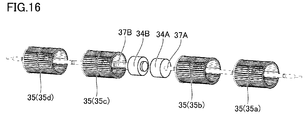
図16は、上述の実施の形態における図5に対応しており、実施の形態6における空気調和機に備えられる送風機を示す斜視図である。上述の実施の形態(図5)においては、4つの多翼遠心ファン35(35a~35d)が、1つの駆動モーター34によって駆動される。
図16は、上述の実施の形態における図5に対応しており、実施の形態6における空気調和機に備えられる送風機を示す斜視図である。上述の実施の形態(図5)においては、4つの多翼遠心ファン35(35a~35d)が、1つの駆動モーター34によって駆動される。
これに対して本実施の形態(図16)においては、2つの多翼遠心ファン35(35a,35b)が、1つの駆動モーター34Aに回転軸37Aを介して連結され、駆動モーター34Aと同軸状となるように水平方向に並んで配置されている。2つの多翼遠心ファン35(35a,35b)が、1つの駆動モーター34Aによって駆動される。
同様に、2つの多翼遠心ファン35(35c,35d)が、1つの駆動モーター34Bに回転軸37Bを介して連結され、駆動モーター34Bと同軸状となるように水平方向に並んで配置されている。2つの多翼遠心ファン35(35c,35d)が、1つの駆動モーター34Bによって駆動される。
複数の多翼遠心ファン35(35a~35d)および駆動モーター34A,34Bは、同軸状となるように水平方向に並んで配置されている。駆動モーター34A,34Bは、水平方向(筺体20の長手方向)において筺体20の中央寄りの位置に配置され、相互に隣り合っている。多翼遠心ファン35(35a,35b)は、水平方向において駆動モーター34Aよりも外側の位置に配置されており、多翼遠心ファン35(35c,35d)は、水平方向において駆動モーター34Bよりも外側の位置に配置されている。
以上のような構成が採用されている場合には、駆動モーター34Aによって駆動される多翼遠心ファン35(35a,35b)と、駆動モーター34Bによって駆動される多翼遠心ファン35(35c,35d)とについて、回転数、風量、吹き出し風向などを異ならせたり、温度や風速の異なる風を左右で吹き分けたりすることが容易に実現でき、使用者に対してよりきめ細かく空気調和された風を提供することが可能となる。
[実施の形態7]
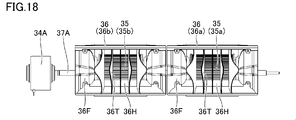
図17は、実施の形態7における空気調和機に備えられる送風機を示す平面図である。図18は、実施の形態7における空気調和機に備えられる送風機の一部(駆動モーター34A、多翼遠心ファン35およびケーシング36(36a,36b))を示す正面図である。本実施の形態は、送風機に備えられるケーシング36の構成において、上述の他の実施の形態と相違している。
図17は、実施の形態7における空気調和機に備えられる送風機を示す平面図である。図18は、実施の形態7における空気調和機に備えられる送風機の一部(駆動モーター34A、多翼遠心ファン35およびケーシング36(36a,36b))を示す正面図である。本実施の形態は、送風機に備えられるケーシング36の構成において、上述の他の実施の形態と相違している。
複数のケーシング36(36a~36d)の各々が、螺旋形状の流路36S(図3,図4)を内側に形成しており、複数の多翼遠心ファン35(35a~35d)の各々の周囲を覆うように配置されているという点は、本実施の形態と上述の各実施の形態とで共通している(図17参照)。また、複数のケーシング36(36a~36d)の各々が、熱交換器38側に向けて開口するように配置されているという点も、本実施の形態と上述の各実施の形態とで共通している(図22参照)。
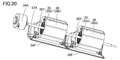
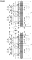
図18~図22に示すように、一方で本実施の形態においては、ケーシング36(36a~36d)の各々における熱交換器38側に、枠部36Fおよび複数のガイドフィン36Tが設けられ、多翼遠心ファン35の軸方向における一方側に通孔36Y(図20)が設けられており、多翼遠心ファン35の軸方向における他方側に通孔36J(図21)が設けられている。通孔36Yおよび通孔36Jは、多翼遠心ファン35の回転軸の方向において、多翼遠心ファン35を挟んで互いに反対側に位置している(図22)。
枠部36Fは、四角枠状に形成され、ケーシング36の前面側において、フランジ状に外側に延出する形状を有している(図18,図19)。枠部36Fの内周面の形状は、多翼遠心ファン35の下流側(前面側)に形成されている開口36Hの流路断面積が、上流側から下流側に向かうにつれて徐々に大きくなるように形成されている。
複数のガイドフィン36Tは、多翼遠心ファン35の回転軸(回転軸37A,37B)に対して垂直な方向に沿って延びるように、枠部36Fの内側で間隔を空けて並んで配置されている。本実施の形態では、計5枚のガイドフィン36Tが、枠部36Fの内側に配置されている。5枚のうちの中央に位置するガイドフィン36Tは、平板状の形状を有している。
平板状のガイドフィン36Tの両外側に位置する2枚のガイドフィン36Tは、上流側から下流側に向かうにつれて外側に向かって湾曲するように形成されている。それらの両外側に位置する2枚のガイドフィン36Tも、上流側から下流側に向かうにつれて外側に向かって湾曲するように形成されている。外側に配置されたガイドフィン36Tは、それらの内側に配置されたガイドフィン36Tに比べて、より急峻に外側に向けて湾曲するように形成されている。
図22に示すように、以上のように構成される複数のガイドフィン36Tは、複数の多翼遠心ファン35(35a~35d)の各々と熱交換器38との間に形成される送風経路を、多翼遠心ファン35の回転軸(回転軸37A,37B)に対して垂直な方向に分割する。当該構成によれば、熱交換器38に対して長手方向においてより均一に送風することができ、より省エネルギー性の高い空気清浄フィルター32を搭載した空気調和機とすることができる。
[実施の形態8]
図23は、実施の形態8における空気調和機に備えられる送風機および熱交換器38M,38Nを模式的に示す平面図である。本実施の形態と上述の各実施の形態とは、以下の点において相違している。
図23は、実施の形態8における空気調和機に備えられる送風機および熱交換器38M,38Nを模式的に示す平面図である。本実施の形態と上述の各実施の形態とは、以下の点において相違している。
本実施の形態の空気調和機は、熱交換器38M,38Nを備えており、これらに対向するように配置される送風機は、駆動モーター34A,34B、複数の多翼遠心ファン35(35a~35d)、および複数のケーシング36(36a~36d)を有している。
(熱交換器38M)
熱交換器38Mは、複数のフィン39F(板材)と、伝熱管39H(管材)とを有している。複数のフィン39Fは、いずれも平板状の形状を有しており、互いに平行な位置関係となるように、多翼遠心ファン35(35a,35b)の回転中心に対して平行な方向に並べられている。伝熱管39Hは、複数の直線部39Sと複数の湾曲部39Wとを含んでいる。複数の直線部39Sは、複数のフィン39Fに取り付けられており、多翼遠心ファン35(35a,35b)の回転中心に対して平行な方向に沿って延在し、互いに平行な位置関係となるように配置されている。複数の湾曲部39Wは、複数の直線部39Sの両外側において、隣り合う2つの直線部39Sの端部同士を接続するように設けられている。多翼遠心ファン35(35a,35b)の回転中心に対して平行な方向において、熱交換器38Mのうちの直線部39Sが設けられている領域の長さはZ1と規定される。
熱交換器38Mは、複数のフィン39F(板材)と、伝熱管39H(管材)とを有している。複数のフィン39Fは、いずれも平板状の形状を有しており、互いに平行な位置関係となるように、多翼遠心ファン35(35a,35b)の回転中心に対して平行な方向に並べられている。伝熱管39Hは、複数の直線部39Sと複数の湾曲部39Wとを含んでいる。複数の直線部39Sは、複数のフィン39Fに取り付けられており、多翼遠心ファン35(35a,35b)の回転中心に対して平行な方向に沿って延在し、互いに平行な位置関係となるように配置されている。複数の湾曲部39Wは、複数の直線部39Sの両外側において、隣り合う2つの直線部39Sの端部同士を接続するように設けられている。多翼遠心ファン35(35a,35b)の回転中心に対して平行な方向において、熱交換器38Mのうちの直線部39Sが設けられている領域の長さはZ1と規定される。
(熱交換器38N)
熱交換器38Nも、複数のフィン39F(板材)と、伝熱管39H(管材)とを有している。複数のフィン39Fは、いずれも平板状の形状を有しており、互いに平行な位置関係となるように、多翼遠心ファン35(35c,35d)の回転中心に対して平行な方向に並べられている。伝熱管39Hは、複数の直線部39Sと複数の湾曲部39Wとを含んでいる。複数の直線部39Sは、複数のフィン39Fに取り付けられており、多翼遠心ファン35(35c,35d)の回転中心に対して平行な方向に沿って延在し、互いに平行な位置関係となるように配置されている。複数の湾曲部39Wは、複数の直線部39Sの両外側において、隣り合う2つの直線部39Sの端部同士を接続するように設けられている。多翼遠心ファン35(35c,35d)の回転中心に対して平行な方向において、熱交換器38Nのうちの直線部39Sが設けられている領域の長さはZ2と規定される。
熱交換器38Nも、複数のフィン39F(板材)と、伝熱管39H(管材)とを有している。複数のフィン39Fは、いずれも平板状の形状を有しており、互いに平行な位置関係となるように、多翼遠心ファン35(35c,35d)の回転中心に対して平行な方向に並べられている。伝熱管39Hは、複数の直線部39Sと複数の湾曲部39Wとを含んでいる。複数の直線部39Sは、複数のフィン39Fに取り付けられており、多翼遠心ファン35(35c,35d)の回転中心に対して平行な方向に沿って延在し、互いに平行な位置関係となるように配置されている。複数の湾曲部39Wは、複数の直線部39Sの両外側において、隣り合う2つの直線部39Sの端部同士を接続するように設けられている。多翼遠心ファン35(35c,35d)の回転中心に対して平行な方向において、熱交換器38Nのうちの直線部39Sが設けられている領域の長さはZ2と規定される。
(多翼遠心ファン35)
多翼遠心ファン35(35a,35b)は、駆動モーター34Aに回転軸37Aを介して連結され、駆動モーター34Aと同軸状となるように水平方向に並んで配置されている。多翼遠心ファン35(35c,35d)は、駆動モーター34Bに回転軸37Bを介して連結され、駆動モーター34Bと同軸状となるように水平方向に並んで配置されている。
多翼遠心ファン35(35a,35b)は、駆動モーター34Aに回転軸37Aを介して連結され、駆動モーター34Aと同軸状となるように水平方向に並んで配置されている。多翼遠心ファン35(35c,35d)は、駆動モーター34Bに回転軸37Bを介して連結され、駆動モーター34Bと同軸状となるように水平方向に並んで配置されている。
(ケーシング36(36a,36b))
ケーシング36(36a,36b)は、各々が螺旋形状の流路を内側に形成し、各々が複数の多翼遠心ファン35(35a,35b)の各々の周囲を覆うとともに、熱交換器38M側に向けて開口するように配置されている。ケーシング36(36a,36b)の各々における熱交換器38Mの側には、内側に送風経路を形成する枠部36Fと、少なくとも1つのガイドフィン36Tとが設けられている。少なくとも1つのガイドフィン36T(本実施の形態では5つ)は、枠部36Fの内側に形成された送風経路を、多翼遠心ファン35(35a,35b)の回転中心に対して垂直な方向に分割するように配置されている。
ケーシング36(36a,36b)は、各々が螺旋形状の流路を内側に形成し、各々が複数の多翼遠心ファン35(35a,35b)の各々の周囲を覆うとともに、熱交換器38M側に向けて開口するように配置されている。ケーシング36(36a,36b)の各々における熱交換器38Mの側には、内側に送風経路を形成する枠部36Fと、少なくとも1つのガイドフィン36Tとが設けられている。少なくとも1つのガイドフィン36T(本実施の形態では5つ)は、枠部36Fの内側に形成された送風経路を、多翼遠心ファン35(35a,35b)の回転中心に対して垂直な方向に分割するように配置されている。
本実施の形態においては、好適な構成として、ケーシング36(36a,36b)の各々について、熱交換器38Mの側で少なくとも1つのガイドフィン36Tによって送風経路が分割されることで形成された複数の開口36Hの各々は、複数の多翼遠心ファン35(35a,35b)の側から熱交換器38Mの側に向かうにつれて、複数の多翼遠心ファン35(35a,35b)の回転中心に対して平行な方向における幅が徐々に拡大するように形成されている。
(ケーシング36(36c,36d))
ケーシング36(36c,36d)は、各々が螺旋形状の流路を内側に形成し、各々が複数の多翼遠心ファン35(35c,35d)の各々の周囲を覆うとともに、熱交換器38M側に向けて開口するように配置されている。ケーシング36(36c,36d)の各々における熱交換器38Nの側には、内側に送風経路を形成する枠部36Fと、少なくとも1つのガイドフィン36Tとが設けられている。少なくとも1つのガイドフィン36T(本実施の形態では5つ)は、枠部36Fの内側に形成された送風経路を、多翼遠心ファン35(35c,35d)の回転中心に対して垂直な方向に分割するように配置されている。
ケーシング36(36c,36d)は、各々が螺旋形状の流路を内側に形成し、各々が複数の多翼遠心ファン35(35c,35d)の各々の周囲を覆うとともに、熱交換器38M側に向けて開口するように配置されている。ケーシング36(36c,36d)の各々における熱交換器38Nの側には、内側に送風経路を形成する枠部36Fと、少なくとも1つのガイドフィン36Tとが設けられている。少なくとも1つのガイドフィン36T(本実施の形態では5つ)は、枠部36Fの内側に形成された送風経路を、多翼遠心ファン35(35c,35d)の回転中心に対して垂直な方向に分割するように配置されている。
本実施の形態においては、好適な構成として、ケーシング36(36c,36d)の各々について、熱交換器38Nの側で少なくとも1つのガイドフィン36Tによって送風経路が分割されることで形成された複数の開口36Hの各々は、複数の多翼遠心ファン35(35c,35d)の側から熱交換器38Nの側に向かうにつれて、複数の多翼遠心ファン35(35c,35d)の回転中心に対して平行な方向における幅が徐々に拡大するように形成されている。
ここで、ケーシング36(36a)に設けられた枠部36Fは、送風経路を内側に形成する内周面36Uを有している。この内周面36Uは、第1出口領域36U1および第2出口領域36U2を含んでいる。
第1出口領域36U1とは、内周面36Uのうち、多翼遠心ファン35(35a)の回転中心に対して平行な方向の一方側においてガイドフィン36Tに重なる部分である。当該部分が第1出口領域36U1と規定される。換言すれば、ケーシング36(36a)に設けられた複数のガイドフィン36Tを上記平行な方向の一方側(ここでは図23紙面内の右側)に向かって投影した場合、第1出口領域36U1とは、内周面36Uのうちの一部分であって、この投影によって形成される複数のガイドフィン36Tの投影像に重なる部分である。
第2出口領域36U2とは、内周面36Uのうち、多翼遠心ファン35(35a)の回転中心に対して平行な方向の他方側においてガイドフィン36Tに重なる部分である。当該部分が第2出口領域36U2と規定される。換言すれば、ケーシング36(36a)に設けられた複数のガイドフィン36Tを上記平行な方向の他方側(ここでは図23紙面内の左側)に向かって投影した場合、第2出口領域36U2とは、内周面36Uのうちの一部分であって、この投影によって形成される複数のガイドフィン36Tの投影像に重なる部分である。
多翼遠心ファン35(35a)によって生成される気流の流れる方向において、第1出口領域36U1のうちの最も上流側に位置する部分と、第2出口領域36U2のうちの最も上流側に位置する部分とが規定される。これらの部分同士の間の、多翼遠心ファン35(35a)の回転中心に対して平行な方向における間隔は、幅w(w1)と規定される。
多翼遠心ファン35(35a)によって生成される気流の流れる方向において、第1出口領域36U1のうちの最も下流側に位置する部分と、第2出口領域36U2のうちの最も下流側に位置する部分とが規定される。これらの部分同士の間の、多翼遠心ファン35(35a)の回転中心に対して平行な方向における間隔は、幅y(y1)と規定される。
ケーシング36(36a)の幅w(w1)の場合と全く同様にして、ケーシング36(36b,36c,36d)のそれぞれについて、幅w(w2,w3,w4)が規定される。ケーシング36(36a)の幅y(y1)の場合と全く同様にして、ケーシング36(36b,36c,36d)のそれぞれについて、幅y(y2,y3,y4)が規定される。
ケーシング36(36a~36d)の各々における幅w(w1~w4)の値を、ケーシング36(36a~36d)のすべてについて合計した値をWとする。すなわち、ここではW=w1+w2+w3+w4である。多翼遠心ファン35(35a~35d)の回転中心に対して平行な方向において、熱交換器38M,38Nのうちの直線部39Sが設けられている領域の長さはZと規定される。本実施の形態の空気調和機は2つの熱交換器38M,38Nを備えているため、Z=Z1+Z2である。
以上のように各値を定義した場合には、複数のうちの少なくとも1つのケーシング36(36a~36d)において、次の式(3)の関係が成立していることが好ましい。
0.7×W/Z≦w/y≦1.3×W/Z ・・・式(3)
すなわち、次の式(4)~(7)のうちのいずれか1つの関係が成立していることが好ましく、これらの式のすべての関係が成立していることがより好ましい。
0.7×W/Z≦w1/y1≦1.3×W/Z ・・・式(4)
0.7×W/Z≦w2/y2≦1.3×W/Z ・・・式(5)
0.7×W/Z≦w3/y3≦1.3×W/Z ・・・式(6)
0.7×W/Z≦w4/y4≦1.3×W/Z ・・・式(7)
一例を挙げると、w1=w2=w3=w4=145[mm]であり、W=145×4=580[mm]である。y1=y2=y3=y4=246[mm]であり、Z1=Z2=500[mm]であり、Z=500×2=1000[mm]である。このような場合には、W/Z=0.58となり、w1/y1=w2/y2=w3/y3=w4/y5=0.59となり、上記の式(4)~(7)のすべての関係が成立している。
0.7×W/Z≦w/y≦1.3×W/Z ・・・式(3)
すなわち、次の式(4)~(7)のうちのいずれか1つの関係が成立していることが好ましく、これらの式のすべての関係が成立していることがより好ましい。
0.7×W/Z≦w1/y1≦1.3×W/Z ・・・式(4)
0.7×W/Z≦w2/y2≦1.3×W/Z ・・・式(5)
0.7×W/Z≦w3/y3≦1.3×W/Z ・・・式(6)
0.7×W/Z≦w4/y4≦1.3×W/Z ・・・式(7)
一例を挙げると、w1=w2=w3=w4=145[mm]であり、W=145×4=580[mm]である。y1=y2=y3=y4=246[mm]であり、Z1=Z2=500[mm]であり、Z=500×2=1000[mm]である。このような場合には、W/Z=0.58となり、w1/y1=w2/y2=w3/y3=w4/y5=0.59となり、上記の式(4)~(7)のすべての関係が成立している。
ここで、冒頭に記載した特許文献9(特開2013-104592号公報)には、複数の多翼遠心ファンを有する空気調和機の構成が開示さている。この構成においては、送風機室と熱交換器室との間に仕切板およびフレームが配置されており、ファンケーシングの下流から熱交換機までの間に長い距離が設けられる必要があり、空気調和機全体としてのサイズが大きくなる可能性がある。
送風機を複数の多翼遠心ファンを用いて構成する場合には、たとえば、複数の多翼遠心ファンの回転中心に対して平行な方向において、多翼遠心ファンの幅の総和を、熱交換器の幅よりも小さくなるように設定することができる。多翼遠心ファンと熱交換器との間の距離が過度に近すぎる場合、ファンから排出された空気はファンが対向する熱交換器の箇所には流通するが、ファンが対向しない熱交換器の箇所にはほとんど流通しなくなり、熱交換器の全体でみると、風量および風速が流通する箇所によって異なり、そのため空気調和機の効率を十分に向上させることが難しくなる場合がある。
これに対して上記の式(4)~(7)の関係を満足するような構成によれば、熱交換器の長手方向における場所に応じて風量が異なったり風速が異なったりすることをより抑制することが可能となり、空気調和機の効率をより高めることができ、さらに省エネ性の高い空気清浄フィルター搭載の空気調和機を実現することが可能となる。
(実施の形態8の変形例)
上述の実施の形態8の中で述べた構成は、上述の実施の形態1~7で述べた構成と組み合わせて実施することも可能であるし、上述の実施の形態1~7で述べた構成とは独立して実施することも可能である。上述の実施の形態8の中で述べた構成を採用する場合には、たとえば、実施の形態1~7で説明したような構成を備えた風向調整部は必須ではない。吸込口22H(図2,3参照)は下面22の側に形成されていなくてもよく、吸込口22Hは、上面21および/または側壁25,26の側に形成されていてもよい。吹出口としては、前方上方吹出部28H(図9)および前方下方吹出部29H(図13)に示す構成に限られず、吹出口は、下面22の側に形成されていてもよく、上面21および/または側壁25,26の側に形成されていてもよい。
上述の実施の形態8の中で述べた構成は、上述の実施の形態1~7で述べた構成と組み合わせて実施することも可能であるし、上述の実施の形態1~7で述べた構成とは独立して実施することも可能である。上述の実施の形態8の中で述べた構成を採用する場合には、たとえば、実施の形態1~7で説明したような構成を備えた風向調整部は必須ではない。吸込口22H(図2,3参照)は下面22の側に形成されていなくてもよく、吸込口22Hは、上面21および/または側壁25,26の側に形成されていてもよい。吹出口としては、前方上方吹出部28H(図9)および前方下方吹出部29H(図13)に示す構成に限られず、吹出口は、下面22の側に形成されていてもよく、上面21および/または側壁25,26の側に形成されていてもよい。
側壁25に吸込口を設ける場合には、側壁25の吸込口を筺体20の内側から覆うようにエアフィルターを配置し、そのエアフィルターの内側に空気清浄フィルターを配置するとよい。側壁26に吸込口を設ける場合には、側壁26の吸込口を筺体20の内側から覆うようにエアフィルターを配置し、そのエアフィルターの内側に空気清浄フィルターを配置するとよい。
エアフィルター31については、吸込口22Hの上方に配置されていなくてもよい。エアフィルター31は、筺体20の内部の側から吸込口22Hを覆うように配置されていれば、たとえばエアフィルター31は吸込口22Hの下方や側方に配置されていても構わない。空気清浄フィルター32についても同様に、エアフィルター31の上方に配置されていなくてもよい。空気清浄フィルター32は、筺体20の内部の側からエアフィルター31を覆うように配置されていれば、たとえば空気清浄フィルター32はエアフィルター31の下方や側方に配置されていても構わない。送風機33は、筺体20の内部に配置されていれば、空気清浄フィルター32の上方に限られず、たとえば空気清浄フィルター32の下方や側方に配置されていても構わない。
実施の形態8の変形例の構成が採用された空気調和機であっても、空気清浄を常に行ないながらより少ない消費エネルギーで空気調和を行なうことができるとともに、従来に比して小型化を図ることが可能である。
[実施の形態9]
図24は、実施の形態9における空気調和機101を示す斜視図である。図25は、図24中のXXV-XXVに沿った矢視断面図である。説明上の便宜のため、図25中には風向調整部40(図1,図2等参照)は図示していない。本実施の形態の上述の各実施の形態とは、以下の点において相違している。
図24は、実施の形態9における空気調和機101を示す斜視図である。図25は、図24中のXXV-XXVに沿った矢視断面図である。説明上の便宜のため、図25中には風向調整部40(図1,図2等参照)は図示していない。本実施の形態の上述の各実施の形態とは、以下の点において相違している。
図24および図25を参照して、本実施の形態9においては、空気調和機101の筺体20が、天井(図11における天井11を参照)に面するように配置される上面21と、床面(同図の床面13を参照)側に位置する下面22と、側壁(同図の側壁12を参照)側に配置される背面23(図25)と、背面23とは反対側に位置する前面24(図25)と、背面23から前面24に向かって右側に位置する側壁26(図24)と、背面23から前面24に向かって左側に位置する側壁25(図24)とを有している。
上述の各実施の形態1~8においては、筺体20の上面21側は閉塞されており、筺体20の下面22に吸込口22H(図3,図4)が形成されている。一方で本実施の形態9においては、図24および図25に示すように、筺体20の上面21側は閉塞されておらず、上面21に吸込口21Hが形成されている。吸込口21Hは、上面21のうちの背面23寄りの部分に設けられている。筺体20の下面22にも吸込口22H(図25)が形成されている。また、上面21の前端部21Fのさらに前方の位置に、水平方向に延びる前面カバー21Cが設けられている。
筺体20の内部には、エアフィルター31および空気清浄フィルター32に加えて、エアフィルター31Aおよび空気清浄フィルター32Aがさらに設けられている。エアフィルター31Aは、上面21側に設けられた吸込口21Hの下方において吸込口21Hを筺体20の内側から塞ぐように配置されており、空気清浄フィルター32Aは、エアフィルター31Aを下方側から覆うように配置されている。空気清浄フィルター32Aも、たとえばHEPAフィルターから構成されている。
本実施の形態の空気調和機101においては、吸込口22H(図25)、エアフィルター31(図25)および空気清浄フィルター32(図25)を通して筺体20の内部に空気が取りこまれるだけでなく、吸込口21H、エアフィルター31Aおよび空気清浄フィルター32Aを通して筺体20の内部に空気が取り込まれる。
空気はその後、熱交換器38および開口27(前側上部開口28または前側下部開口29)を通過し、風向調整部40(図24)によって風向きを調整された状態で、前面24側に形成された吹出口(すなわち、図10に示す前方上方吹出部28Hまたは図14に示す前方下方吹出部29H)を通して機外に吹き出される。本実施の形態9の空気調和機101によれば、上述の各実施の形態1~8における空気調和機に比べて風量を増大させることができる。上面21側を閉塞せずに上面21側に吸込口21Hを設けるという技術的思想は、上述の各実施の形態1~8で説明した思想に組み合わせて実施することも可能である。
以上、実施の形態について説明したが、上記の開示内容はすべての点で例示であって制限的なものではない。本発明の技術的範囲は請求の範囲によって示され、請求の範囲と均等の意味および範囲内でのすべての変更が含まれることが意図される。
10 部屋、11 天井、12,14,16,25,26,36W 側壁、13 床面、20 筺体、21 上面、21C 前面カバー、21F,24T 前端部、22 下面、21H,22H 吸込口、23 背面、24 前面、25A,25B 前端、27,36H 開口、28 前側上部開口、28H 前方上方吹出部、29 前側下部開口、29H 前方下方吹出部、31,31A エアフィルター、32,32A 空気清浄フィルター、33 送風機、34,34A,34B 駆動モーター、35 多翼遠心ファン、35F 羽根部、35P,35Q 枠体、35R ボス、36 ケーシング、36F 枠部、36J,36Y 通孔、36S 流路、36T ガイドフィン、36U 内周面、36U1 第1出口領域、36U2 第2出口領域、37,37A,37B 回転軸、38,38M,38N 熱交換器、38A 上部熱交換部、38B 下部熱交換部、39F フィン、39H 伝熱管、39S 直線部、39W 湾曲部、40 風向調整部、41 可動パネル、41A 上端、41B 下端、41T,42T,43T 軸支部、41U 支持部、42 上部風向板、42A,43A 先端、43 下部風向板、100,101 空気調和機。
Claims (15)
- 部屋の側壁上部または天井に設置される空気調和機であって、
前記天井に面するように配置される上面と、床面側に位置する下面と、前記側壁側に配置される背面と、を有し、前記下面側に吸込口が形成され、前記背面とは反対側である前面側に開口が形成された筺体と、
前記吸込口の上方において前記吸込口を覆うように配置されたエアフィルターと、
前記エアフィルターの上方に配置された空気清浄フィルターと、
前記空気清浄フィルターの上方に配置された送風機と、
前記送風機の前方または前方上方に配置された熱交換器と、
前記開口を前方側から覆うように配置された風向調整部と、を備え、
前記送風機は、
駆動モーターと、
前記駆動モーターに回転軸を介して連結され、前記駆動モーターと同軸状となるように水平方向に並んで配置された複数の多翼遠心ファンと、を含み、
前記駆動モーターによって複数の前記多翼遠心ファンが回転することにより、前記吸込口、前記エアフィルターおよび前記空気清浄フィルターを通して前記筺体の内部に空気が取りこまれるとともに、空気は前記熱交換器および前記開口を通過して前記風向調整部によって風向きを調整された状態で、前記風向調整部の上部側または下部側に形成されている吹出口を通して機外に吹き出される、
空気調和機。 - 前記駆動モーターは、水平方向において前記筺体の中央寄りの位置に配置され、
複数の前記多翼遠心ファンは、水平方向において前記駆動モーターよりも外側の位置に配置されている、
請求項1に記載の空気調和機。 - 前記多翼遠心ファンの直径をD[mm]とし、前記筺体の高さをh[mm]とすると、
0.9×h≦2×D≦1.1×hの関係が成立している、
請求項2に記載の空気調和機。 - 前記筺体の奥行きをL[mm]とすると、
0.9×L≦h+1/2×D≦1.1×Lの関係が成立している、
請求項3に記載の空気調和機。 - 前記送風機は、複数のケーシングをさらに有し、
複数の前記ケーシングの各々は、螺旋形状の流路を内側に形成し、複数の前記多翼遠心ファンの各々の周囲を覆うとともに、前記熱交換器側に向けて開口するように配置されており、
複数の前記ケーシングの各々における前記熱交換器側には、複数の前記多翼遠心ファンの各々と前記熱交換器との間に形成される送風経路を、前記多翼遠心ファンの回転軸に対して垂直な方向に分割する、1つまたは複数のガイドフィンが設けられている、
請求項2から請求項4のいずれか1項に記載の空気調和機。 - 冷房運転時または送風運転時には、前記風向調整部によって前記筺体の前方上方に前記吹出口が形成され、当該吹出口を通して空気が吹き出される、
請求項1から請求項5のいずれか1項に記載の空気調和機。 - 暖房運転時には、前記風向調整部によって前記筺体の前方下方に前記吹出口が形成され、当該吹出口を通して空気が吹き出される、
請求項1から請求項5のいずれかに記載の空気調和機。 - 前記吹出口は、
前記筺体の前方上方に形成され、前記風向調整部により開閉される前方上方吹出部と、
前記筺体の前方下方に形成され、前記風向調整部により開閉される前方下方吹出部と、を含み、
冷房運転または送風運転が行なわれる際には、前記風向調整部によって前記前方上方吹出部が開放されるとともに前記前方下方吹出部は閉塞され、
暖房運転が行なわれる際には、前記風向調整部によって前記前方上方吹出部が閉塞されるとともに前記前方下方吹出部は開放される、
請求項1から請求項5のいずれかに記載の空気調和機。 - 前記風向調整部は、板状の形状を有し前記開口を前面側から覆うように配置される可動パネルを含み、
前記可動パネルは、前記筺体の上下方向における略中央の位置で軸支されており、
前記可動パネルは、冷房運転または送風運転が行なわれる際には下方側に回動して前記前方上方吹出部を開放するとともに前記前方下方吹出部を閉塞し、暖房運転が行なわれる際には上方側に回動して前記前方上方吹出部を閉塞するとともに前記前方下方吹出部を開放する、
請求項8に記載の空気調和機。 - 前記空気清浄フィルターは、HEPAフィルターから構成されている、
請求項1から請求項9のいずれか1項に記載の空気調和機。 - 部屋の側壁上部または天井に設置される空気調和機であって、
前記天井に面するように配置される上面と、床面側に位置する下面と、前記側壁側に配置される背面と、前記背面とは反対側に配置される前面と、を有し、前記部屋の空気を自身の内部に取り込むための吸込口と、前記内部で調和された空気を前記部屋の中に送り出すための吹出口と、が形成された筺体と、
前記筺体の前記内部の側から前記吸込口を覆うように配置されたエアフィルターと、
前記筺体の前記内部の側から前記エアフィルターを覆うように配置された空気清浄フィルターと、
前記筺体の前記内部に配置された送風機と、
前記送風機の前方または前方上方に配置された熱交換器と、を備え、
前記送風機は、
駆動モーターと、
前記駆動モーターに回転軸を介して連結され、前記駆動モーターと同軸状となるように水平方向に並んで配置された複数の多翼遠心ファンと、
各々が螺旋形状の流路を内側に形成し、各々が複数の前記多翼遠心ファンの各々の周囲を覆うとともに前記熱交換器側に向けて開口するように配置された複数のケーシングと、を有し、
複数の前記ケーシングの各々における前記熱交換器の側には、
内側に送風経路を形成する枠部と、
前記枠部の内側に形成された前記送風経路を、前記多翼遠心ファンの回転中心に対して垂直な方向に分割する、少なくとも1つのガイドフィンと、が設けられている、
空気調和機。 - 複数の前記ケーシングの各々について、前記熱交換器の側で前記ガイドフィンによって前記送風経路が分割されることで形成された複数の開口の各々は、前記多翼遠心ファンの側から前記熱交換器の側に向かうにつれて、前記回転中心に対して平行な方向における幅が徐々に拡大するように形成されている、
請求項11に記載の空気調和機。 - 前記熱交換器は、
平板状の形状を有し、互いに平行な位置関係となるように前記平行な方向に並べられた複数のフィンと、
複数の前記フィンに取り付けられ、前記平行な方向に沿って延在し、互いに平行な位置関係となるように配置された複数の直線部と、複数の前記直線部の両外側において2つの前記直線部の端部同士を接続するように設けられた複数の湾曲部とを含む、伝熱管と、を有し、
複数の前記ケーシングの各々に設けられた前記枠部は、前記送風経路を内側に形成する内周面を有し、
前記内周面のうち、前記平行な方向の一方側において前記ガイドフィンに重なる部分を第1出口領域と規定し、前記平行な方向の他方側において前記ガイドフィンに重なる部分を第2出口領域と規定し、
前記第1出口領域のうちの最も上流側に位置する部分と前記第2出口領域のうちの最も上流側に位置する部分との間の前記平行な方向における間隔をwとし、
前記第1出口領域のうちの最も下流側に位置する部分と前記第2出口領域のうちの最も下流側に位置する部分との間の前記平行な方向における間隔をyとし、
複数の前記ケーシングの各々におけるwの値を、複数の前記ケーシングのすべてについて合計した値をWとし、
前記平行な方向において、前記熱交換器のうちの前記直線部が設けられている領域の長さをZとした場合には、
複数のうちの少なくとも1つの前記ケーシングにおいて、
0.7×W/Z≦w/y≦1.3×W/Zの関係が成立している、
請求項12に記載の空気調和機。 - 前記多翼遠心ファンの直径をD[mm]とし、前記筺体の高さをh[mm]とすると、
0.9×h≦2×D≦1.1×hの関係が成立している、
請求項11から請求項13のいずれか1項に記載の空気調和機。 - 前記空気清浄フィルターは、HEPAフィルターから構成されている、
請求項11から請求項14のいずれか1項に記載の空気調和機。
Applications Claiming Priority (4)
| Application Number | Priority Date | Filing Date | Title |
|---|---|---|---|
| JP2017-077718 | 2017-04-10 | ||
| JP2017077718 | 2017-04-10 | ||
| JP2017140996 | 2017-07-20 | ||
| JP2017-140996 | 2017-07-20 |
Publications (1)
| Publication Number | Publication Date |
|---|---|
| WO2018189933A1 true WO2018189933A1 (ja) | 2018-10-18 |
Family
ID=63792464
Family Applications (1)
| Application Number | Title | Priority Date | Filing Date |
|---|---|---|---|
| PCT/JP2017/031551 Ceased WO2018189933A1 (ja) | 2017-04-10 | 2017-09-01 | 空気調和機 |
Country Status (2)
| Country | Link |
|---|---|
| TW (1) | TW201837395A (ja) |
| WO (1) | WO2018189933A1 (ja) |
Cited By (2)
| Publication number | Priority date | Publication date | Assignee | Title |
|---|---|---|---|---|
| CN112833463A (zh) * | 2019-11-25 | 2021-05-25 | 夏普株式会社 | 空气调节机 |
| JP2024009352A (ja) * | 2019-11-25 | 2024-01-19 | シャープ株式会社 | 空気調和機 |
Families Citing this family (1)
| Publication number | Priority date | Publication date | Assignee | Title |
|---|---|---|---|---|
| CN113757884B (zh) * | 2021-09-22 | 2024-03-15 | 江苏中锦新能源科技有限公司 | 一种大型吊顶空气净化机机壳 |
Citations (13)
| Publication number | Priority date | Publication date | Assignee | Title |
|---|---|---|---|---|
| JPS4851155U (ja) * | 1971-10-12 | 1973-07-04 | ||
| JPS6171623U (ja) * | 1984-10-12 | 1986-05-15 | ||
| JPH0712856U (ja) * | 1993-07-09 | 1995-03-03 | 株式会社富士通ゼネラル | 空気調和機の室内機 |
| JPH10205876A (ja) * | 1997-01-20 | 1998-08-04 | Matsushita Electric Ind Co Ltd | 空気清浄フィルターの取付構造 |
| JP2005315538A (ja) * | 2004-04-30 | 2005-11-10 | Fujitsu General Ltd | 空気調和機 |
| JP2005315537A (ja) * | 2004-04-30 | 2005-11-10 | Fujitsu General Ltd | 空気調和機 |
| JP2007292405A (ja) * | 2006-04-26 | 2007-11-08 | Mitsubishi Electric Corp | 空気調和機 |
| JP2010117110A (ja) * | 2008-11-14 | 2010-05-27 | Panasonic Corp | 空気調和機の室内機 |
| JP2010249465A (ja) * | 2009-04-17 | 2010-11-04 | Daikin Ind Ltd | 空気調和装置の室内機 |
| JP2015081733A (ja) * | 2013-10-23 | 2015-04-27 | 三菱電機株式会社 | 送風機及び制御方法 |
| WO2015097821A1 (ja) * | 2013-12-26 | 2015-07-02 | 東芝キヤリア株式会社 | 空気調和機および熱交換器 |
| JP2015169389A (ja) * | 2014-03-07 | 2015-09-28 | 三菱重工業株式会社 | 空気調和機 |
| JP2016183794A (ja) * | 2015-03-25 | 2016-10-20 | 株式会社富士通ゼネラル | 空気調和機 |
-
2017
- 2017-09-01 WO PCT/JP2017/031551 patent/WO2018189933A1/ja not_active Ceased
- 2017-09-04 TW TW106130187A patent/TW201837395A/zh unknown
Patent Citations (13)
| Publication number | Priority date | Publication date | Assignee | Title |
|---|---|---|---|---|
| JPS4851155U (ja) * | 1971-10-12 | 1973-07-04 | ||
| JPS6171623U (ja) * | 1984-10-12 | 1986-05-15 | ||
| JPH0712856U (ja) * | 1993-07-09 | 1995-03-03 | 株式会社富士通ゼネラル | 空気調和機の室内機 |
| JPH10205876A (ja) * | 1997-01-20 | 1998-08-04 | Matsushita Electric Ind Co Ltd | 空気清浄フィルターの取付構造 |
| JP2005315538A (ja) * | 2004-04-30 | 2005-11-10 | Fujitsu General Ltd | 空気調和機 |
| JP2005315537A (ja) * | 2004-04-30 | 2005-11-10 | Fujitsu General Ltd | 空気調和機 |
| JP2007292405A (ja) * | 2006-04-26 | 2007-11-08 | Mitsubishi Electric Corp | 空気調和機 |
| JP2010117110A (ja) * | 2008-11-14 | 2010-05-27 | Panasonic Corp | 空気調和機の室内機 |
| JP2010249465A (ja) * | 2009-04-17 | 2010-11-04 | Daikin Ind Ltd | 空気調和装置の室内機 |
| JP2015081733A (ja) * | 2013-10-23 | 2015-04-27 | 三菱電機株式会社 | 送風機及び制御方法 |
| WO2015097821A1 (ja) * | 2013-12-26 | 2015-07-02 | 東芝キヤリア株式会社 | 空気調和機および熱交換器 |
| JP2015169389A (ja) * | 2014-03-07 | 2015-09-28 | 三菱重工業株式会社 | 空気調和機 |
| JP2016183794A (ja) * | 2015-03-25 | 2016-10-20 | 株式会社富士通ゼネラル | 空気調和機 |
Cited By (4)
| Publication number | Priority date | Publication date | Assignee | Title |
|---|---|---|---|---|
| CN112833463A (zh) * | 2019-11-25 | 2021-05-25 | 夏普株式会社 | 空气调节机 |
| JP2021085553A (ja) * | 2019-11-25 | 2021-06-03 | シャープ株式会社 | 空気調和機 |
| JP2024009352A (ja) * | 2019-11-25 | 2024-01-19 | シャープ株式会社 | 空気調和機 |
| JP7703620B2 (ja) | 2019-11-25 | 2025-07-07 | シャープ株式会社 | 空気調和機 |
Also Published As
| Publication number | Publication date |
|---|---|
| TW201837395A (zh) | 2018-10-16 |
Similar Documents
| Publication | Publication Date | Title |
|---|---|---|
| US20120015599A1 (en) | Air conditioner, casing, and decorative panel | |
| JP2004012060A (ja) | 空気調和機の室内ユニット及び空気調和機 | |
| JP2006029702A (ja) | 空気調和機 | |
| CN108386905B (zh) | 空调 | |
| JPH09210390A (ja) | 空気調和機 | |
| CN103370578B (zh) | 空气调节机 | |
| WO2018189932A1 (ja) | 空気調和機 | |
| JP2007010259A (ja) | 空気調和機 | |
| TWI654377B (zh) | Air conditioner | |
| WO2018189933A1 (ja) | 空気調和機 | |
| JP2005003244A (ja) | 空気調和機 | |
| TWI675993B (zh) | 空氣調和機 | |
| CN114046566A (zh) | 空调室内机 | |
| JP2017161185A (ja) | 空気調和機 | |
| JP4670437B2 (ja) | 空気調和機 | |
| JP2007107435A (ja) | ターボファン及びこれを用いた空気調和機 | |
| JP4639911B2 (ja) | 空気調和機 | |
| JP4706305B2 (ja) | 空気調和機 | |
| JP3812467B2 (ja) | 遠心送風機の羽根車及びそれを用いた遠心送風機 | |
| CN210688516U (zh) | 空调室外机和空调器 | |
| CN217685471U (zh) | 空调室内机 | |
| KR200156408Y1 (ko) | 분리형 공기조화기의 실내기 | |
| CN1214215C (zh) | 整体式空调器 | |
| US12422149B2 (en) | Air conditioner | |
| CN119222625A (zh) | 空调室内机及其送风控制方法、空调器 |
Legal Events
| Date | Code | Title | Description |
|---|---|---|---|
| 121 | Ep: the epo has been informed by wipo that ep was designated in this application |
Ref document number: 17905838 Country of ref document: EP Kind code of ref document: A1 |
|
| NENP | Non-entry into the national phase |
Ref country code: DE |
|
| 122 | Ep: pct application non-entry in european phase |
Ref document number: 17905838 Country of ref document: EP Kind code of ref document: A1 |
|
| NENP | Non-entry into the national phase |
Ref country code: JP |