WO2018189891A1 - ハイブリッド車両の制御方法及びハイブリッド車両の制御装置 - Google Patents
ハイブリッド車両の制御方法及びハイブリッド車両の制御装置 Download PDFInfo
- Publication number
- WO2018189891A1 WO2018189891A1 PCT/JP2017/015338 JP2017015338W WO2018189891A1 WO 2018189891 A1 WO2018189891 A1 WO 2018189891A1 JP 2017015338 W JP2017015338 W JP 2017015338W WO 2018189891 A1 WO2018189891 A1 WO 2018189891A1
- Authority
- WO
- WIPO (PCT)
- Prior art keywords
- regenerative torque
- upper limit
- torque
- clutch
- engine
- Prior art date
- Legal status (The legal status is an assumption and is not a legal conclusion. Google has not performed a legal analysis and makes no representation as to the accuracy of the status listed.)
- Ceased
Links
Images






Classifications
-
- B—PERFORMING OPERATIONS; TRANSPORTING
- B60—VEHICLES IN GENERAL
- B60L—PROPULSION OF ELECTRICALLY-PROPELLED VEHICLES; SUPPLYING ELECTRIC POWER FOR AUXILIARY EQUIPMENT OF ELECTRICALLY-PROPELLED VEHICLES; ELECTRODYNAMIC BRAKE SYSTEMS FOR VEHICLES IN GENERAL; MAGNETIC SUSPENSION OR LEVITATION FOR VEHICLES; MONITORING OPERATING VARIABLES OF ELECTRICALLY-PROPELLED VEHICLES; ELECTRIC SAFETY DEVICES FOR ELECTRICALLY-PROPELLED VEHICLES
- B60L7/00—Electrodynamic brake systems for vehicles in general
- B60L7/10—Dynamic electric regenerative braking
- B60L7/14—Dynamic electric regenerative braking for vehicles propelled by AC motors
-
- B—PERFORMING OPERATIONS; TRANSPORTING
- B60—VEHICLES IN GENERAL
- B60W—CONJOINT CONTROL OF VEHICLE SUB-UNITS OF DIFFERENT TYPE OR DIFFERENT FUNCTION; CONTROL SYSTEMS SPECIALLY ADAPTED FOR HYBRID VEHICLES; ROAD VEHICLE DRIVE CONTROL SYSTEMS FOR PURPOSES NOT RELATED TO THE CONTROL OF A PARTICULAR SUB-UNIT
- B60W10/00—Conjoint control of vehicle sub-units of different type or different function
- B60W10/02—Conjoint control of vehicle sub-units of different type or different function including control of driveline clutches
-
- B—PERFORMING OPERATIONS; TRANSPORTING
- B60—VEHICLES IN GENERAL
- B60W—CONJOINT CONTROL OF VEHICLE SUB-UNITS OF DIFFERENT TYPE OR DIFFERENT FUNCTION; CONTROL SYSTEMS SPECIALLY ADAPTED FOR HYBRID VEHICLES; ROAD VEHICLE DRIVE CONTROL SYSTEMS FOR PURPOSES NOT RELATED TO THE CONTROL OF A PARTICULAR SUB-UNIT
- B60W10/00—Conjoint control of vehicle sub-units of different type or different function
- B60W10/04—Conjoint control of vehicle sub-units of different type or different function including control of propulsion units
- B60W10/08—Conjoint control of vehicle sub-units of different type or different function including control of propulsion units including control of electric propulsion units, e.g. motors or generators
-
- B—PERFORMING OPERATIONS; TRANSPORTING
- B60—VEHICLES IN GENERAL
- B60W—CONJOINT CONTROL OF VEHICLE SUB-UNITS OF DIFFERENT TYPE OR DIFFERENT FUNCTION; CONTROL SYSTEMS SPECIALLY ADAPTED FOR HYBRID VEHICLES; ROAD VEHICLE DRIVE CONTROL SYSTEMS FOR PURPOSES NOT RELATED TO THE CONTROL OF A PARTICULAR SUB-UNIT
- B60W10/00—Conjoint control of vehicle sub-units of different type or different function
- B60W10/18—Conjoint control of vehicle sub-units of different type or different function including control of braking systems
-
- B—PERFORMING OPERATIONS; TRANSPORTING
- B60—VEHICLES IN GENERAL
- B60W—CONJOINT CONTROL OF VEHICLE SUB-UNITS OF DIFFERENT TYPE OR DIFFERENT FUNCTION; CONTROL SYSTEMS SPECIALLY ADAPTED FOR HYBRID VEHICLES; ROAD VEHICLE DRIVE CONTROL SYSTEMS FOR PURPOSES NOT RELATED TO THE CONTROL OF A PARTICULAR SUB-UNIT
- B60W20/00—Control systems specially adapted for hybrid vehicles
- B60W20/40—Controlling the engagement or disengagement of prime movers, e.g. for transition between prime movers
-
- F—MECHANICAL ENGINEERING; LIGHTING; HEATING; WEAPONS; BLASTING
- F16—ENGINEERING ELEMENTS AND UNITS; GENERAL MEASURES FOR PRODUCING AND MAINTAINING EFFECTIVE FUNCTIONING OF MACHINES OR INSTALLATIONS; THERMAL INSULATION IN GENERAL
- F16H—GEARING
- F16H59/00—Control inputs to control units of change-speed- or reversing-gearings for conveying rotary motion
- F16H59/14—Inputs being a function of torque or torque demand
-
- F—MECHANICAL ENGINEERING; LIGHTING; HEATING; WEAPONS; BLASTING
- F16—ENGINEERING ELEMENTS AND UNITS; GENERAL MEASURES FOR PRODUCING AND MAINTAINING EFFECTIVE FUNCTIONING OF MACHINES OR INSTALLATIONS; THERMAL INSULATION IN GENERAL
- F16H—GEARING
- F16H61/00—Control functions within control units of change-speed- or reversing-gearings for conveying rotary motion ; Control of exclusively fluid gearing, friction gearing, gearings with endless flexible members or other particular types of gearing
- F16H61/02—Control functions within control units of change-speed- or reversing-gearings for conveying rotary motion ; Control of exclusively fluid gearing, friction gearing, gearings with endless flexible members or other particular types of gearing characterised by the signals used
-
- Y—GENERAL TAGGING OF NEW TECHNOLOGICAL DEVELOPMENTS; GENERAL TAGGING OF CROSS-SECTIONAL TECHNOLOGIES SPANNING OVER SEVERAL SECTIONS OF THE IPC; TECHNICAL SUBJECTS COVERED BY FORMER USPC CROSS-REFERENCE ART COLLECTIONS [XRACs] AND DIGESTS
- Y02—TECHNOLOGIES OR APPLICATIONS FOR MITIGATION OR ADAPTATION AGAINST CLIMATE CHANGE
- Y02T—CLIMATE CHANGE MITIGATION TECHNOLOGIES RELATED TO TRANSPORTATION
- Y02T10/00—Road transport of goods or passengers
- Y02T10/60—Other road transportation technologies with climate change mitigation effect
-
- Y—GENERAL TAGGING OF NEW TECHNOLOGICAL DEVELOPMENTS; GENERAL TAGGING OF CROSS-SECTIONAL TECHNOLOGIES SPANNING OVER SEVERAL SECTIONS OF THE IPC; TECHNICAL SUBJECTS COVERED BY FORMER USPC CROSS-REFERENCE ART COLLECTIONS [XRACs] AND DIGESTS
- Y02—TECHNOLOGIES OR APPLICATIONS FOR MITIGATION OR ADAPTATION AGAINST CLIMATE CHANGE
- Y02T—CLIMATE CHANGE MITIGATION TECHNOLOGIES RELATED TO TRANSPORTATION
- Y02T10/00—Road transport of goods or passengers
- Y02T10/60—Other road transportation technologies with climate change mitigation effect
- Y02T10/62—Hybrid vehicles
-
- Y—GENERAL TAGGING OF NEW TECHNOLOGICAL DEVELOPMENTS; GENERAL TAGGING OF CROSS-SECTIONAL TECHNOLOGIES SPANNING OVER SEVERAL SECTIONS OF THE IPC; TECHNICAL SUBJECTS COVERED BY FORMER USPC CROSS-REFERENCE ART COLLECTIONS [XRACs] AND DIGESTS
- Y02—TECHNOLOGIES OR APPLICATIONS FOR MITIGATION OR ADAPTATION AGAINST CLIMATE CHANGE
- Y02T—CLIMATE CHANGE MITIGATION TECHNOLOGIES RELATED TO TRANSPORTATION
- Y02T10/00—Road transport of goods or passengers
- Y02T10/60—Other road transportation technologies with climate change mitigation effect
- Y02T10/7072—Electromobility specific charging systems or methods for batteries, ultracapacitors, supercapacitors or double-layer capacitors
-
- Y—GENERAL TAGGING OF NEW TECHNOLOGICAL DEVELOPMENTS; GENERAL TAGGING OF CROSS-SECTIONAL TECHNOLOGIES SPANNING OVER SEVERAL SECTIONS OF THE IPC; TECHNICAL SUBJECTS COVERED BY FORMER USPC CROSS-REFERENCE ART COLLECTIONS [XRACs] AND DIGESTS
- Y02—TECHNOLOGIES OR APPLICATIONS FOR MITIGATION OR ADAPTATION AGAINST CLIMATE CHANGE
- Y02T—CLIMATE CHANGE MITIGATION TECHNOLOGIES RELATED TO TRANSPORTATION
- Y02T10/00—Road transport of goods or passengers
- Y02T10/60—Other road transportation technologies with climate change mitigation effect
- Y02T10/72—Electric energy management in electromobility
Definitions
- the present disclosure relates to a hybrid vehicle control method and control device.
- the present disclosure has been made paying attention to the above-described problem, and provides a hybrid vehicle control method and a hybrid vehicle control device capable of preventing a significant reduction in vehicle deceleration accompanying a limitation of regenerative torque during coasting.
- the purpose is to provide.
- the engine is disconnected from the drive wheel during coasting by the accelerator release operation, and the coast regeneration torque generated by the motor generator is set to the target regeneration torque. Further, when a predetermined regenerative restriction condition is satisfied, the upper limit value of the motor generator's coast regenerative torque is limited to a value smaller than the maximum value of the regenerative torque that can be generated by the motor generator. Then, after the restriction of the upper limit value of the coast regenerative torque is started, an engagement command is output to the engine clutch until the upper limit value of the coast regenerative torque matches the target regenerative torque.
- FIG. 1 is an overall configuration diagram illustrating an FF hybrid vehicle to which a hybrid vehicle control method and a control device according to a first embodiment are applied. It is a figure which shows an example of the mode transition map used in Example 1.
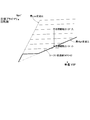
- FIG. It is a figure which shows an example of the shift schedule map used in Example 1.
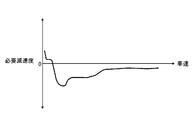
- FIG. 3 is a block diagram illustrating a configuration of a coast clutch control unit according to the first embodiment. It is a figure which shows an example of the required deceleration setting map used in Example 1.
- FIG. It is a figure which shows an example of the engine speed upper limit setting map used in Example 1.
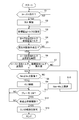
- FIG. 3 is a flowchart illustrating a flow of a clutch control process executed in the first embodiment.
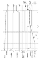
- FIG. 4 is a time chart showing characteristics of vehicle speed, accelerator opening, brake pedal force, first clutch command, coast regeneration torque, regeneration torque upper limit value, and engine friction torque when motor regeneration is restricted during coasting in Example 1.
- FIG. is there. 4 is a time chart showing characteristics of a motor rotation speed, an engine rotation speed, a vehicle deceleration, a fuel cut flag, a fuel cut prohibition flag, and a fuel cut state when a motor regeneration restriction occurs during coasting in the first embodiment.
- Example 1 shown in the drawings.
- Example 1 First, the configuration will be described.
- the hybrid vehicle control method and control apparatus according to the first embodiment are applied to an FF hybrid vehicle including a parallel hybrid drive system called a 1-motor / 2-clutch.
- the configuration of the FF hybrid vehicle to which the control method and the control apparatus of the first embodiment are applied is described as “detailed configuration of drive system”, “detailed configuration of operation mode”, “detailed configuration of control system”, “clutch during coasting”
- the drive system of the FF hybrid vehicle includes an engine Eng, a first clutch CL1 (engine clutch), a motor generator MG, a second clutch CL2, a continuously variable transmission CVT, and a final gear FG. And a left drive wheel LT and a right drive wheel RT.
- the engine Eng is torque-controlled so that the engine torque matches the command value by controlling the intake air amount by the throttle actuator, the fuel injection amount by the injector, and the ignition timing by the spark plug. Further, when the engine Eng is not in the combustion operation state but in the cranking operation state in which the first clutch CL1 is engaged in the fuel cut state (fuel supply stop), the engine friction torque is caused by the frictional sliding resistance between the piston and the inner wall of the cylinder. Is generated.
- the first clutch CL1 is interposed at a position between the engine Eng and the motor generator MG and corresponds to an engine clutch disposed between the engine Eng and the left and right drive wheels LT, RT.
- the first clutch CL1 for example, a normally open dry multi-plate clutch or the like is used, and fastening / slip fastening / release between the engine Eng and the motor generator MG is performed. If the first clutch CL1 is engaged, the engine Eng is connected to the left and right drive wheels LT, RT, and motor torque + engine torque is transmitted to the second clutch CL2. If the first clutch CL1 is in the released state, the engine Eng is disconnected from the left and right drive wheels LT, RT, and only the motor torque is transmitted to the second clutch CL2.
- the engagement / slip engagement / release of the first clutch CL1 is performed by hydraulic control in which a transmission torque (clutch torque capacity) is generated according to the clutch hydraulic pressure (pressing force).
- Motor generator MG has an AC synchronous motor structure, and performs motor torque control and motor rotation speed control when starting and running, and recovers (charges) vehicle kinetic energy to battery 9 by regenerative brake control during deceleration. It is.
- the second clutch CL2 is a normally open wet multi-plate clutch or wet multi-plate brake provided in the forward / reverse switching mechanism of the continuously variable transmission CVT, and the transmission torque (clutch torque capacity) according to the clutch hydraulic pressure (pressing force). ) Occurs.
- the second clutch CL2 transmits the torque output from the engine Eng and the motor generator MG (when the first clutch CL1 is engaged) to the left and right drive wheels LT, RT via the continuously variable transmission CVT and the final gear FG. Communicate.
- the second clutch CL2 is set at a position between the continuously variable transmission CVT and the left and right drive wheels LT, RT, in addition to being set at a position between the motor generator MG and the continuously variable transmission CVT. May be set.
- the continuously variable transmission CVT includes a primary pulley PrP connected to the transmission input shaft input, a secondary pulley SeP connected to the transmission output shaft output, and a pulley belt spanned between the primary pulley PrP and the secondary pulley SeP.
- BE is a belt type continuously variable transmission.
- the primary pulley PrP has a fixed sheave fixed to the transmission input shaft input and a movable sheave slidably supported on the transmission input shaft input.
- the secondary pulley SeP has a fixed sheave fixed to the transmission output shaft output and a movable sheave supported slidably on the transmission output shaft output.
- the pulley belt BE is a metal belt wound between the primary pulley PrP and the secondary pulley SeP, and is sandwiched between the fixed sheave and the movable sheave.
- a pin type belt or a VDT type belt is used as the pulley belt BE.
- the pulley width of both pulleys PrP and SeP is changed, and the diameter of the clamping surface of the pulley belt BE is changed to freely control the gear ratio (pulley ratio).
- the gear ratio changes to the low side.
- the gear ratio changes to the high side.
- the FF hybrid vehicle of the first embodiment has an electric travel mode (hereinafter referred to as “EV mode”), a hybrid travel mode (hereinafter referred to as “HEV mode”), and the like as operation modes by the drive system described above. .
- EV mode electric travel mode
- HEV mode hybrid travel mode
- HEV mode hybrid travel mode
- the left and right drive wheels LT are set so that the first clutch CL1 is disengaged, the second clutch CL2 is engaged, the engine Eng is disconnected from the drive system, and only the motor generator MG can be transmitted. Connect to RT.
- the motor generator MG is controlled to the power running side during driving to apply driving force to the vehicle, and the motor generator MG is used as a driving source (motor).
- the motor generator MG is controlled to the regeneration side and used as a power generation drive source (generator), and the regenerative torque generated at this time is used as the braking force.
- controlling the motor generator MG to the power running side means that the motor generator MG is supplied with power from the inverter 8 to the motor generator MG, and the motor generator MG drives the left and right driving wheels LT, RT to enter a power running state. It is to control MG.
- Controlling the motor generator MG to the regeneration side means that the motor generator MG is controlled so that the rotational energy held by the motor generator MG and the left and right drive wheels LT, RT flows into the inverter 8. That is.
- the first clutch CL1 is engaged
- the second clutch CL2 is engaged
- both the motor generator MG and the engine Eng are connected to the left and right driving wheels LT, RT so that the driving force can be transmitted.
- the motor generator MG is controlled to the power running side and fuel is supplied to the engine Eng, and the engine Eng and the motor generator MG are used as a traveling drive source.
- motor generator MG is controlled to the regeneration side, and the regeneration torque generated at this time is used as a braking force.
- the engine Eng is in a cranking operation state (rotates along with the motor generator MG) to generate friction torque, and the friction torque (engine friction torque) generated by the engine Eng is used as a braking force.
- the mode transition between the “EV mode” and the “HEV mode” is performed using the target driving force and the mode transition map shown in FIG.
- a positive target driving force (required acceleration) and an operating point P corresponding to the vehicle speed are set on the power running control region set above the target driving force zero axis shown in FIG.
- “EV mode” is selected when the operating point P is in the EV region
- “HEV mode” is selected when the operating point P is in the HEV region.
- an operating point P corresponding to a negative target driving force (required deceleration) is set on the regeneration control region set below the target driving force zero axis shown in FIG.
- EV mode is selected when the operating point P is in the EV region
- HEV mode is selected when the operating point P is in the HEV region.
- the target driving force is calculated based on the vehicle speed and the driving operation of the driver (in this case, the accelerator opening and the brake pedaling force), the target vehicle speed, and the actual vehicle speed.
- the control system of the FF hybrid vehicle includes an integrated controller 14, a transmission controller 15, a clutch controller 16, an engine controller 17, a motor controller 18, and a battery controller 19. .
- the brake sensor 21, the lever position sensor 22, and the vehicle speed sensor 23 are provided.
- the integrated controller 14 calculates a target driving force from the battery state, the accelerator opening, the vehicle speed (a value synchronized with the transmission output speed), the hydraulic oil temperature, and the like. Then, based on the calculation result of the target driving force, the command value for each actuator (motor generator MG, engine Eng, first clutch CL1, second clutch CL2, continuously variable transmission CVT) is calculated, and via CAN communication line 25 To each of the controllers 15, 16, 17, 18, and 19.
- the transmission controller 15 performs shift control by controlling the pulley hydraulic pressure supplied to the primary pulley PrP and the secondary pulley SeP of the continuously variable transmission CVT so as to achieve the shift command from the integrated controller 14.
- the shift control by the transmission controller 15 uses the shift schedule map shown in FIG. 3 and the driving point based on the vehicle speed VSP and the target driving force DF (the absolute value of the required acceleration or the required deceleration). This is done by determining the target primary rotational speed Npri * from the points (VSP, DF). As shown in FIG. 3, the speed change schedule changes the speed ratio within a speed ratio range based on the lowest gear ratio and the highest gear ratio in accordance with the operating point (VSP, DF).
- the thick line in FIG. 3 indicates a coast transmission line indicating a gear ratio during coasting. For example, when the vehicle speed VSP decreases and the vehicle speed VSP decreases during coasting at the highest gear ratio, the maximum gear ratio is Downshift toward the lowest gear ratio.
- the clutch controller 16 inputs sensor information from the engine speed sensor 11, the motor speed sensor 6, the transmission input speed sensor 7, etc., and outputs a clutch hydraulic pressure command value to the first clutch CL1 and the second clutch CL2. To do. Thereby, the pressing force of the first clutch CL1 is set and the pressing force of the second clutch CL2 is set.
- the engine controller 17 inputs the sensor information from the engine speed sensor 11 and controls the torque of the engine Eng so as to achieve the engine torque command value from the integrated controller 14.
- a fuel cut command is input from the integrated controller 14, the fuel supply to the engine Eng is stopped.
- the motor controller 18 outputs a control command to the inverter 8 so as to achieve the motor torque command value, the motor rotation speed command value, and the regenerative power command from the integrated controller 14, and the motor torque control and motor rotation of the motor generator MG are performed. Number control and regenerative brake control.
- the motor controller 18 manages the motor generator temperature and transmits motor temperature information to the integrated controller 14.
- the inverter 8 performs DC / AC mutual conversion. When the motor generator MG is controlled to the power running side, the discharge current from the battery 9 is changed to the drive current of the motor generator MG to regenerate the motor generator MG. When the control is performed to the side, the generated current from the motor generator MG is converted into a charging current for the battery 9.
- the battery controller 19 manages the charge capacity SOC and battery temperature of the battery 9, and transmits the SOC information and the battery temperature information to the integrated controller 14.
- the integrated controller 14 (a hybrid vehicle control device) includes a coast clutch control unit 30 and a coast fuel supply control unit 40.
- the coast clutch control unit 30 releases the first clutch CL1 and separates the engine Eng from the left and right drive wheels LT and RT and generates regenerative torque (coast regenerative torque) by the motor generator MG during coasting.
- regenerative brake control is performed in which the coast regenerative torque is set to the target regenerative torque.
- the upper limit value (regenerative torque upper limit value) of coast regenerative torque is smaller than the maximum regenerative torque value (regenerative torque maximum value) that can be generated by motor generator MG. Limit to value.
- an engagement command is output to the first clutch CL1, and the engine Eng is driven to the left and right drive wheels LT, Connect to RT.
- the coast clutch control unit 30 includes a coast determination unit 31, a coast regeneration control unit 32, a clutch control unit 33, and a regeneration restriction unit 34.
- the coast determination unit 31 determines whether or not the FF hybrid vehicle is in a coasting state based on the accelerator opening and the brake depression force. Sensor information from the accelerator opening sensor 10 and the brake sensor 21 is input to the coast determination unit 31. The coast determination unit 31 determines that the vehicle is in the coasting state when the brake pedal force is zero and the accelerator opening is in the release operation region, and outputs a coast determination signal.
- the “coast running” is a state in which there is no driving force request from the driver and the vehicle runs with inertia.
- the “accelerator opening release operation area” is an arbitrary opening area where it can be determined that the accelerator pedal is released, for example, from the accelerator opening 2/8 to zero (accelerator release state). This is an area.
- the coast regeneration control unit 32 receives a coast determination signal from the coast determination unit 31 and sensor information from the accelerator opening sensor 10 and the vehicle speed sensor 23.
- the coast regeneration control unit 32 controls the motor generator MG to the regeneration side during coasting to generate coast regeneration torque.
- regenerative brake control is performed so that the coast regenerative torque becomes a target regenerative torque that is a target value.
- the target regenerative torque is set according to the vehicle deceleration (necessary deceleration) required during coasting.
- the “necessary deceleration” is determined according to the vehicle speed and the accelerator opening, and FIG. 5 shows the relationship between the necessary deceleration and the vehicle speed when the accelerator opening is zero.
- the “required deceleration during coasting” is set to a value smaller than the vehicle deceleration that occurs when the maximum value of regenerative torque that can be generated by motor generator MG (maximum value of regenerative torque) is generated.
- the “regenerative torque maximum value” is determined by the rating of the motor generator MG.
- the coast regeneration control unit 32 sets an upper limit value (regeneration torque upper limit value) of the coast regeneration torque.
- the regenerative torque upper limit value is set to the regenerative torque maximum value when the limit torque command is not input from the regenerative restriction unit 34.
- the regenerative torque upper limit value is set to a value obtained by subtracting the limit torque ⁇ T from the maximum regenerative torque value when a limit torque command is input from the regenerative limiting unit 34, and is limited to a value smaller than the maximum regenerative torque value. The That is, the coast regenerative torque is limited according to the limit torque command when the limit torque command is input from the regeneration limiter 34.
- the clutch control unit 33 includes a coast determination signal from the coast determination unit 31, target regeneration torque information and regeneration torque upper limit value information from the coast regeneration control unit 32, motor speed sensor 6, vehicle speed sensor 23, and brake sensor 21. Are input.
- the clutch control unit 33 outputs a CL1 release control command for releasing the first clutch CL1 when the coast determination signal is input. Further, the clutch control unit 33 determines the magnitude of the regenerative torque upper limit value and the magnitude of the motor rotational speed Nm, and the motor revolving torque Nm is set in advance while the regenerative torque upper limit value reaches or falls below the maximum value of the target regenerative torque.
- a CL1 engagement control command for engaging the first clutch CL1 is output. Further, the clutch control unit 33 outputs the first clutch release command when the brake pedal is depressed and the vehicle speed is equal to or lower than a predetermined stoppage threshold value while the first clutch CL1 is engaged during coasting. Allow.
- the “engine speed upper limit value” is the engine speed at which the engine Eng is in the cranking operation state and does not give the driver a sense of incongruity due to the vibration and sound of the engine Eng (acoustic vibration performance is acceptable). 6 is set according to the map and vehicle speed shown in FIG. Further, the “stop threshold” is a vehicle speed at which it can be determined that the vehicle has stopped, and is set to a detection limit value of the vehicle speed sensor 23, for example.
- Regenerative restriction unit 34 receives SOC information of battery 9 and temperature information of motor generator MG. The regenerative restriction unit 34 determines whether or not the regenerative restriction condition is satisfied based on the SOC and the motor temperature. When it is determined that the regenerative restriction condition is satisfied, a limit torque ⁇ T that restricts the regenerative torque upper limit value is calculated and a limit torque command is output. The limit torque information is input to the coast regeneration control unit 32 together with the limit torque command.
- the “regenerative restriction condition” is a condition that is set based on a predetermined value of SOC or motor temperature, for example. Further, the “limit torque ⁇ T” and its rate (change slope) are set according to the SOC, motor temperature, change speed, change amount, and the like. This “limit torque ⁇ T” is a limit amount of the regenerative torque upper limit value with respect to the maximum regenerative torque value.
- the coast fuel supply control unit 40 prohibits the fuel supply to the engine Eng and does not permit the fuel supply request while the regenerative torque upper limit value is restricted during coasting. That is, when the coast determination signal and the limit torque command are input, the coast time fuel supply restriction unit 40 outputs a fuel cut command for stopping the fuel supply to the engine Eng and sets the fuel cut flag to “1”. Set. Thus, for example, even if a fuel supply request is output by a heating ON operation and the fuel cut prohibition flag is set to “1”, fuel supply to the engine Eng is not permitted, the fuel supply request is ignored, and the fuel cut state To maintain.
- FIG. 7 is a flowchart illustrating a coast clutch control process executed by the coast clutch control unit according to the first embodiment.
- the coast clutch control process is repeatedly executed at a preset cycle while the vehicle is running in the FF hybrid vehicle (while the vehicle speed exceeds a predetermined threshold).
- step S1 the coast determination unit 31 determines whether or not coasting is in progress. If YES (coast running), the process proceeds to step S2, and if NO (non-coast running), step S1 is repeated.
- whether or not coasting is being performed is determined based on the accelerator opening and the brake pedaling force, and the coasting is being performed when the accelerator pedal opening is in a predetermined release operation region and the brake pedaling force is zero. It is judged.
- step S2 following the determination that coasting is being performed in step S1, the clutch control unit 33 outputs a CL1 release command for releasing the first clutch CL1, and the process proceeds to step S2.
- the engine Eng is disconnected from the left and right drive wheels LT, RT, and transits to the “EV mode”.
- step S3 following the output of the CL1 release command in step S2, the coast regeneration control unit 32 sets a target regeneration torque that is a target value of the coast regeneration torque generated by the motor generator MG, and the process proceeds to step S4.
- the target regeneration torque is set according to the required vehicle deceleration determined based on the accelerator opening and the vehicle speed.
- step S4 following the setting of the target regenerative torque in step S3, regenerative brake control is performed so that the coast regenerative torque matches the target regenerative torque set in step S3, and the process proceeds to step S5.
- step S5 following the execution of the regenerative brake control in step S4, the regenerative restriction unit 34 determines whether or not a predetermined regenerative restriction condition is satisfied. If YES (condition is satisfied), the process proceeds to step S6. If NO (condition is not satisfied), the process returns to step S3.
- whether or not the regeneration restriction condition is satisfied is determined based on the SOC information of battery 9 or the temperature information of motor generator MG.
- step S6 following the determination that the regeneration restriction condition is satisfied in step S5, the regeneration restriction unit 34 restricts the upper limit value (regeneration torque upper limit value) of the coast regeneration torque by the restriction torque ⁇ T, and the process proceeds to step S7.
- the limit torque ⁇ T is set according to the SOC, the motor temperature, the rate of change, the amount of change, and the like.
- a value obtained by subtracting the limit torque ⁇ T from the regenerative torque maximum value is set as a new regenerative torque upper limit value.
- step S7 following the restriction of the regenerative torque upper limit value in step S6, the clutch control unit 33 determines whether or not the regenerative torque upper limit value restricted in step S6 is less than or equal to the maximum value of the target regenerative torque. to decide. If YES (regenerative torque upper limit value ⁇ target regenerative torque maximum value), the process proceeds to step S8. If NO (regenerative torque upper limit value> target regenerative torque maximum value), the process returns to step S6.
- the “maximum value of the target regenerative torque” is set according to the maximum value of the necessary deceleration that is arbitrarily set ( ⁇ the maximum value of the regenerative torque).
- step S8 following the determination that the regenerative torque upper limit value ⁇ the target regenerative torque maximum value in step S7, the motor speed Nm that becomes the input speed to the engine Eng is set in advance by the clutch control unit 33. It is determined whether or not it is less than the number upper limit (Ne upper limit). If YES (Nm ⁇ Ne upper limit value), the process proceeds to step S9. If NO (Nm> Ne upper limit value), the process proceeds to step S10.
- the “engine speed upper limit value” is set according to the map shown in FIG. 6 and the vehicle speed.
- step S9 following the determination of Nm ⁇ Ne upper limit value in step S8, the clutch control unit 33 does not give the driver a sense of incongruity due to the vibration or sound of the engine Eng when the engine Eng is in the cranking operation state. (Sound vibration performance is acceptable), a CL1 engagement command for engaging the first clutch CL1 is output, and the process proceeds to step S11.
- the engine Eng is connected to the left and right drive wheels LT, RT, and transits to the “HEV mode”. At this time, the engine Eng is in a cranking operation state with fuel supply prohibited.
- step S10 following the determination of Nm> Ne upper limit value in step S8, the clutch control unit 33 gives the driver a sense of incongruity with the vibration and sound of the engine Eng when the engine Eng is in the cranking operation state ( As the sound vibration performance is unacceptable), a motor rotational speed command for matching the motor rotational speed Nm to the engine rotational speed upper limit value (Ne upper limit value) is output, and the process returns to step S8.
- step S11 following the output of the CL1 engagement command in step S9, the clutch control unit 33 determines whether or not the brake pedal has been depressed (ON operation). If YES (brake ON), the process proceeds to step S12. If NO (brake OFF), step S11 is repeated. Here, whether or not the brake pedal is depressed is determined based on brake pedal force information from the brake sensor 21.
- step S12 following the determination that the brake is ON in step S11, the clutch control unit 33 determines whether or not the vehicle speed is equal to or less than a predetermined stop threshold. If YES (vehicle speed ⁇ stop threshold), the process proceeds to step S13. If NO (vehicle speed> stop threshold), the process returns to step S11.
- step S13 following the determination that vehicle speed ⁇ stop threshold in step S12, the clutch control unit 33 allows the driver to release the first clutch CL1, and proceeds to the end, assuming that the driver intends to stop.
- a HEV ⁇ EV transition request is generated based on the target driving force and the mode transition map shown in FIG. 2, a CL1 release command for releasing the first clutch CL1 is output, and a transition is made to “EV mode”.
- FIG. 8 is a flowchart illustrating the flow of the coast-time fuel cut process executed by the coast-time fuel supply control unit according to the first embodiment.
- the coast-time fuel cut processing configuration of the first embodiment will be described with reference to FIG. This coast-time fuel cut process is repeatedly executed while the FF hybrid vehicle is running on the coast.
- step S20 it is determined whether or not a predetermined regeneration restriction condition is satisfied. If YES (condition is satisfied), the process proceeds to step S21. If NO (condition is not satisfied), the process proceeds to step S22.
- whether or not the regeneration restriction condition is satisfied is determined based on the SOC information of battery 9 or the temperature information of motor generator MG.
- step S21 following the determination that the regeneration restriction condition is satisfied in step S20, the fuel cut flag is set to “1”, and the process proceeds to step S23.
- the “fuel cut flag” is a flag that prohibits the fuel supply to the engine Eng (does not permit the fuel supply).
- step S22 following the determination that the regeneration restriction condition is not satisfied in step S20, the fuel cut flag is set to “zero”, and the process proceeds to return.
- the fuel cut flag By setting the fuel cut flag to “zero”, fuel supply to the engine Eng is permitted (fuel supply is not prohibited), and when a fuel supply request is generated, fuel is supplied to the engine Eng.
- the engine Eng is connected to the left and right drive wheels LT, RT, the cranking operation state is brought about as the motor generator MG rotates.
- step S24 it is determined whether a fuel supply request has been made following the fuel cut in step S23. If YES (fuel supply requested), the process proceeds to step S25, and if NO (no fuel supply requested), the process proceeds to step S26.
- the fuel supply request is generated, for example, by an ON operation of heating in the vehicle.
- step S25 following the determination that there is a fuel supply request in step S24, the fuel cut prohibition flag is set to “1”, and the process proceeds to step S27.
- the “fuel cut prohibition flag” is a flag that prohibits fuel cut (permits fuel supply).
- step S26 following the determination that there is no fuel supply request in step S24, the fuel cut prohibition flag is set to "zero", and the process proceeds to return. By setting this fuel cut prohibition flag to “zero”, the fuel supply request to the engine Eng is withdrawn.
- [Deceleration fluctuation suppression when regeneration is limited] 9A and 9B illustrate vehicle speed, accelerator opening, brake pedal force, first clutch command, coast regeneration torque, regeneration torque upper limit value, engine friction torque, and motor speed when motor regeneration is restricted during coasting in the first embodiment. It is a time chart which shows each characteristic of motor rotation speed, engine rotation speed, vehicle deceleration, fuel cut prohibition flag, and fuel cut state.
- FIG. 9A and FIG. 9B the deceleration fluctuation
- the FF hybrid vehicle of Embodiment 1 during traveling, when the accelerator opening degree at time t 1 when the time chart shown in FIGS. 9A and 9B is released operated to a predetermined release operation region, the brake in this case Since the pedal effort is zero, in the flowchart shown in FIG. 7, the process proceeds from step S1, step S2, step S3, and step S4.
- first clutch CL1 is in the released state from time t 1 earlier.
- the motor generator MG is controlled on the regeneration side to generate a coast regeneration torque.
- This coast regeneration torque outputs a vehicle deceleration according to the request based on the accelerator opening and the vehicle speed.
- Regenerative brake control of motor generator MG is performed so as to coincide with the set “target regenerative torque”.
- this coast regeneration torque becomes a load on the left and right drive wheels LT and RT of the FF hybrid vehicle.
- the vehicle deceleration according to the request occurs, the braking force is applied to the left and right drive wheels LT, RT, and the vehicle speed gradually decreases.
- step S5 when the temperature of the motor generator MG by performing the regeneration regeneration limitation condition is satisfied such as by increasing, in the flowchart shown in FIG. 7 proceeds to step S5 ⁇ step S6.
- the limit torque ⁇ T is calculated, and the upper limit value of the coast regenerative torque (regeneration torque upper limit value) is limited by the limit torque ⁇ T. That is, a value obtained by subtracting the calculated limit torque ⁇ T from the maximum regenerative torque value that can be generated by motor generator MG is set as a new regenerative torque upper limit value.
- the regenerative torque upper limit value is limited to a value smaller than the regenerative torque maximum value.
- the regenerative torque upper limit value reaches the maximum value of the target regenerative torque, it is determined that regenerative torque upper limit value ⁇ target regenerative torque maximum value. Then, the process proceeds from step S7 to step S8. Meanwhile, in this time t 4 time, since the motor rotation speed Nm is the input rotational speed of the engine Eng is above the engine rotational speed upper limit value (Ne upper limit), the process proceeds to step S10, the motor rotation speed Nm Is controlled to match the engine speed upper limit value (Ne upper limit value). Also in the time t 4 when the absolute value of the target regenerative torque is below the absolute value of the regenerative torque upper limit value. For this reason, the coast regenerative torque can be made to coincide with the target regenerative torque, the vehicle deceleration can be output according to the demand, and the fluctuation (decrease) in the vehicle deceleration does not occur.
- step S8 the process proceeds to step S8 ⁇ step S9.
- an engagement command is output to the first clutch CL1, and the first clutch CL1 is engaged.
- the engine Eng is connected to the left and right drive wheels LT, RT, and the engine friction torque can be transmitted to the left and right drive wheels LT, RT.
- regenerative torque upper limit value in the middle engagement of the first clutch CL1 is equal to the target regenerative torque, then the absolute value of the target regenerative torque is greater than the absolute value of the regenerative torque upper limit value.
- the coast regenerative torque cannot be matched with the target regenerative torque, and the vehicle deceleration according to the request cannot be output, resulting in a decrease in the vehicle deceleration.
- Example 1 before the time t 6 when the decrease of the vehicle deceleration starts to occur, engagement command of the first clutch CL1 is output at time t 5 the time. Therefore, the time t 7 when immediately after time t 6, the occurrence of clutch torque capacity of the first clutch CL1 starts, the engine Eng is started to rotate. The first clutch CL1 is fully engaged at time t 8 when the engine rotational speed and the motor speed is matched. Further, since the first clutch CL1 is completely engaged, the engine friction torque is sufficiently transmitted to the left and right driving LT and RT, and this engine friction torque becomes a load on the left and right driving LT and RT of the FF hybrid vehicle. In other words, the limit amount of the coast regenerative torque due to the regenerative restriction is compensated by the engine friction torque, and the necessary vehicle deceleration can be output.
- the timing of the regenerative torque upper limit value is equal to the target regenerative torque (time t 6 time), i.e., engaging the first clutch CL1 after detecting that became can match coasting regenerative torque to the target regenerative torque in the case of outputting the engagement command to become securely slower than the timing example 1 in which the first clutch CL1 is completely engaged (time t 8 point). Therefore, as shown by a two-dot chain line in FIG. 9B, the timing for compensating for the coast regenerative torque by the engine friction torque is slower than in the case of the first embodiment, and the vehicle deceleration is greatly reduced. In particular, during coast driving, the driver hardly operates the pedal, and the driver can easily feel the fluctuation of the deceleration. Therefore, the slower the compensation of the regenerative torque limit amount by the engine friction torque, the more the driver feels uncomfortable.
- engagement command of the first clutch CL1 is time t since the start of restriction of the upper limit value of coasting regeneration torque at two time points, regeneration at time t 6 when the torque upper limit target regenerative torque It is outputted during a match (time t 5 when in the first embodiment). That is, the engagement command for the first clutch CL1 can be output before the coast regeneration torque cannot be matched with the target regeneration torque.
- step S20 is determined in the flowchart shown in FIG. 8, and when the regenerative restriction condition is not satisfied (the upper limit value of the coast regenerative torque (regenerative torque upper limit value) is restricted. If not, the process proceeds from step S20 to step S22. Thus, the fuel cut flag is set to “zero” and fuel cut is not prohibited. Therefore, when a fuel supply request is generated, fuel supply to the engine Eng is appropriately performed.
- step S20 ⁇ step S21 ⁇ Proceed to step S23.
- the fuel cut flag is set to "1" with the fuel supply is prohibited at time t 2 time, the fuel cut is executed.
- the time t 2 than before the fuel cut is executed the fuel supply state is in a "cut".
- the fuel cut prohibition flag is set to “1”.
- the fuel cut prohibition flag at time t 3 time is set to "1"
- fuel cut because the fuel supply is prohibited It continues to be executed and the fuel supply state remains “cut”.
- step S24 step S26 Is set to “zero”.
- step S26 Is set to “zero”.
- the fuel cut flag is set to “1”, so that the fuel supply continues to be prohibited and the fuel cut state is maintained.
- step S9 when the brake pedal is depressed, coast traveling is released.
- the regenerative restriction condition is also not established, so that the process proceeds from step S20 to step S22, and the fuel cut flag is set to “zero”.
- fuel can be supplied. For example, when a fuel supply request is generated in association with a heating ON operation, fuel supply to the engine Eng is executed.
- step S11 ⁇ step in the flowchart shown in FIG. 7 Proceed to S12. Then, at time t 10, if the vehicle speed reaches a stop threshold value, the release of the first clutch CL1 is permitted proceeds to step S13.
- release command to the first clutch CL1 is output.
- the release of the first clutch CL1 is permitted. That is, it is permitted to output a release command to the first clutch CL1.
- the engine Eng can be separated from the left and right drive wheels LT, RT to “EV mode” when the vehicle stops due to the will of the driver, and the uncomfortable feeling that engine noise is generated when the vehicle stops can be alleviated.
- first clutch CL1 disposed between the engine Eng and the drive wheels LT and RT
- first clutch CL1 In the control method of a hybrid vehicle that is fastened and connects the engine Eng to the drive wheels LT and RT, and releases the engine clutch (first clutch CL1) to separate the engine Eng from the drive wheels LT and RT.
- the engine clutch (first clutch CL1) is released to disconnect the engine Eng from the drive wheels LT and RT, and the coast regeneration torque generated by the motor generator MG is the target regeneration torque.
- the upper limit value of the coast regenerative torque (regenerative torque upper limit value) is set to a value smaller than the maximum regenerative torque value (regenerative torque maximum value) that can be generated by the motor generator MG.
- Limit The engine clutch is started after the upper limit value (regenerative torque upper limit value) of the coast regenerative torque is limited until the upper limit value (regenerative torque upper limit value) of the coast regenerative torque matches the target regenerative torque.
- a configuration in which an engagement command is output to (first clutch CL1) is adopted.
- a clutch control unit 33 for releasing the engine clutch (first clutch CL1) and separating the engine Eng from the drive wheels LT and RT during coasting by an accelerator release operation;
- a coast regeneration control unit 32 for controlling a coast regeneration torque generated by the motor generator MG to a target regeneration torque during the coast running;
- a regenerative restriction unit 34 for limiting The clutch control unit 33 starts the restriction of the upper limit value (regeneration torque upper limit value) of the coast regeneration torque until the upper limit value (regeneration torque upper limit value) of the coast regeneration torque matches the target regeneration torque. In the meantime, the engagement command is output to the engine clutch (first clutch CL1). As a result, it is possible to prevent a significant reduction in vehicle deceleration that accompanies the restriction of the regenerative torque during coasting and to prevent the driver from feeling uncomfortable.
- the first clutch CL1 is determined at the timing when Nm ⁇ Ne upper limit value is determined. Shows an example in which a fastening command is output. However, when the regenerative torque upper limit value reaches the maximum value of the target regenerative torque (when it is determined that the regenerative torque upper limit value ⁇ the target regenerative torque maximum value), the engagement command is output to the first clutch CL1. Also good.
- the equal driving force line that defines the maximum value of the target regenerative torque is set to a minimum value that does not cross the EV-HEV switching line. Therefore, when the regenerative torque upper limit value is below the maximum value of the target regenerative torque, the equal driving force line that defines the driving force according to the vehicle speed straddles the EV region and the HEV region.
- the operating point on the operation mode setting map moves from ⁇ EV area '' ⁇ ⁇ HEV area '' ⁇ ⁇ EV area ''
- the operation mode is hunting from “EV mode” ⁇ “HEV mode” ⁇ “EV mode”, and the engagement / release of the first clutch CL1 is repeated in a short time.
- EV-HEV hunting occurs when the engagement command is output to the first clutch CL1 when the upper limit of the regenerative torque matches the maximum value of the target regenerative torque and the engine Eng is connected to the left and right drive wheels LT, RT.
- the engine friction torque can be regenerated efficiently by delaying the timing at which the engine friction torque becomes a load on the motor generator MG.
- the timing for outputting the engagement command to the first clutch CL1 is not limited to the example shown in the first embodiment.
- the first clutch engagement command may be output immediately after the limit of the regenerative torque upper limit is started.
- the first clutch engagement command may be output after the start of limiting the regenerative torque upper limit value, when the deviation width between the regenerative torque upper limit value and the target regenerative torque becomes an arbitrarily set value, or the deviation width between the regenerative torque upper limit value and the regenerative torque maximum value is When the value is arbitrarily set.
- the motor speed Nm has fallen below the engine speed upper limit value. If so, the first clutch engagement command may be output immediately after it is determined that the regenerative torque upper limit value ⁇ the target regenerative torque maximum value.
- the first clutch engagement command may be output based on time. That is, the first clutch engagement command may be output after a predetermined time ( ⁇ time until the regenerative torque upper limit value matches the target regenerative torque) has elapsed after the start of limiting the regenerative torque upper limit value.
- the upper limit value of the coast regenerative torque is limited at a predetermined constant limit rate after the limit of the regenerative torque upper limit value is started.
- the limiting rate of the regenerative torque upper limit value is arbitrarily set according to the change speed and change amount of the motor temperature, the battery temperature, the SOC, etc., the magnitude of the target regenerative torque, and the like. That is, the limit rate may be such that after the start of limiting the regenerative torque upper limit, the regenerative torque upper limit is rapidly limited and then gradually limited.
- the “accelerator opening release operation region” is exemplified as the region from the accelerator opening 2/8 to zero (accelerator release state), but is not limited thereto.
- an “accelerator opening release operation region” may be entered, and it may be determined that the vehicle is coasting.
- the hybrid vehicle control method according to the present disclosure includes an engine clutch that connects / disconnects the engine Eng to / from the drive wheels LT and RT, and controls the motor generator MG to the regeneration side during coasting to generate coast regeneration torque. Any vehicle can be applied.
Landscapes
- Engineering & Computer Science (AREA)
- Mechanical Engineering (AREA)
- Transportation (AREA)
- Chemical & Material Sciences (AREA)
- Combustion & Propulsion (AREA)
- General Engineering & Computer Science (AREA)
- Automation & Control Theory (AREA)
- Power Engineering (AREA)
- Hybrid Electric Vehicles (AREA)
- Control Of Vehicle Engines Or Engines For Specific Uses (AREA)
- Electric Propulsion And Braking For Vehicles (AREA)
Abstract
コースト走行中の回生トルクの制限に伴う車両減速度の大幅な低減を防止することができ、ドライバの違和感を防止することができるハイブリッド車両の制御方法を提供すること。 アクセル解放操作によるコースト走行時、エンジンクラッチ(CL1)を解放すると共に、モータジェネレータ(MG)にて発生させるコースト回生トルクを目標回生トルクにする。所定の回生制限条件が成立したとき、回生トルク上限値をモータジェネレータ(MG)で発生可能な回生トルク最大値よりも小さい値に制限する。そして、回生トルク上限値の制限開始から、この回生トルク上限値が目標回生トルクに一致するまでの間に、エンジンクラッチ(CL1)に締結指令を出力する構成とした。
Description
本開示は、ハイブリッド車両の制御方法及び制御装置に関するものである。
従来、回生制限等によりモータジェネレータが発生する回生トルクのみでは、要求に応じた車両減速度を出力することができない場合、エンジンのフリクショントルクで車両減速度を補うハイブリッド車両の制御方法が知られている(例えば、特許文献1参照)。
しかしながら、回生トルクのみで必要な車両減速度を出力することができないと判断してからエンジンを駆動輪に接続し、エンジンフリクショントルクで車両減速度を補うと、車両減速度の補填が遅れる。そのため、回生制限による車両減速度の低減幅が大きくなり、いわゆるG段差が生じてドライバに違和感を与えるという問題が生じる。特に、アクセルペダルの操作量がほぼゼロの状態で走行するコースト走行時では、ドライバが車両減速度の変動を感じやすいため、減速度の低減幅を適切に抑制する必要がある。
本開示は、上記問題に着目してなされたもので、コースト走行中の回生トルクの制限に伴う車両減速度の大幅な低減を防止することができるハイブリッド車両の制御方法及びハイブリッド車両の制御装置を提供することを目的とする。
上記目的を達成するため、アクセル解放操作によるコースト走行時、エンジンを駆動輪から切り離すと共に、モータジェネレータで発生するコースト回生トルクを目標回生トルクにする。
また、所定の回生制限条件が成立したとき、モータジェネレータのコースト回生トルクの上限値を、モータジェネレータにて発生可能な回生トルクの最大値よりも小さい値に制限する。
そして、コースト回生トルクの上限値の制限を開始してから、このコースト回生トルクの上限値が目標回生トルクに一致するまでの間に、エンジンクラッチに締結指令を出力する。
また、所定の回生制限条件が成立したとき、モータジェネレータのコースト回生トルクの上限値を、モータジェネレータにて発生可能な回生トルクの最大値よりも小さい値に制限する。
そして、コースト回生トルクの上限値の制限を開始してから、このコースト回生トルクの上限値が目標回生トルクに一致するまでの間に、エンジンクラッチに締結指令を出力する。
よって、本開示では、コースト走行中の回生トルクの制限に伴う車両減速度の大幅な低減を防止することができる。
以下、本開示のハイブリッド車両の制御方法及び制御装置を実施するための形態を、図面に示す実施例1に基づいて説明する。
(実施例1)
まず、構成を説明する。
実施例1におけるハイブリッド車両の制御方法及び制御装置は、1モータ・2クラッチと呼ばれるパラレルハイブリッド駆動系を備えるFFハイブリッド車両に適用する。以下、実施例1の制御方法及び制御装置が適用されたFFハイブリッド車両の構成を、「駆動系の詳細構成」、「運転モードの詳細構成」、「制御系の詳細構成」、「コースト時クラッチ制御処理構成」、「コースト時フューエルカット処理構成」に分けて説明する。
まず、構成を説明する。
実施例1におけるハイブリッド車両の制御方法及び制御装置は、1モータ・2クラッチと呼ばれるパラレルハイブリッド駆動系を備えるFFハイブリッド車両に適用する。以下、実施例1の制御方法及び制御装置が適用されたFFハイブリッド車両の構成を、「駆動系の詳細構成」、「運転モードの詳細構成」、「制御系の詳細構成」、「コースト時クラッチ制御処理構成」、「コースト時フューエルカット処理構成」に分けて説明する。
[駆動系の詳細構成]
FFハイブリッド車両の駆動系は、図1に示すように、エンジンEngと、第1クラッチCL1(エンジンクラッチ)と、モータジェネレータMGと、第2クラッチCL2と、無段変速機CVTと、ファイナルギヤFGと、左駆動輪LTと、右駆動輪RTと、を備えている。
FFハイブリッド車両の駆動系は、図1に示すように、エンジンEngと、第1クラッチCL1(エンジンクラッチ)と、モータジェネレータMGと、第2クラッチCL2と、無段変速機CVTと、ファイナルギヤFGと、左駆動輪LTと、右駆動輪RTと、を備えている。
エンジンEngは、スロットルアクチュエータによる吸入空気量とインジェクタによる燃料噴射量と、点火プラグによる点火時期の制御により、エンジントルクが指令値と一致するようにトルク制御される。また、エンジンEngは、燃焼運転状態ではなく、フューエルカット状態(燃料供給停止)で第1クラッチCL1を締結したクランキング運転状態とすると、ピストンとシリンダー内壁との摩擦摺動抵抗等によりエンジンフリクショントルクを発生する。
第1クラッチCL1は、エンジンEngとモータジェネレータMGとの間の位置に介装され、エンジンEngと左右駆動輪LT,RTの間に配置されたエンジンクラッチに相当する。この第1クラッチCL1としては、例えば、ノーマルオープンの乾式多板クラッチ等が用いられ、エンジンEng~モータジェネレータMG間の締結/スリップ締結/解放を行なう。この第1クラッチCL1が締結状態なら、エンジンEngが左右駆動輪LT,RTに接続され、モータトルク+エンジントルクが第2クラッチCL2へと伝達される。また、第1クラッチCL1が解放状態なら、エンジンEngが左右駆動輪LT,RTから切り離され、モータトルクのみが第2クラッチCL2へと伝達される。そして、第1クラッチCL1の締結/スリップ締結/解放は、クラッチ油圧(押付力)に応じて伝達トルク(クラッチトルク容量)が発生する油圧制御にて行われる。
モータジェネレータMGは、交流同期モータ構造であり、発進時や走行時にモータトルク制御やモータ回転数制御を行うと共に、減速時に回生ブレーキ制御による車両運動エネルギーのバッテリ9への回収(充電)を行なうものである。
第2クラッチCL2は、無段変速機CVTの前後進切替機構に設けられたノーマルオープンの湿式多板クラッチや湿式多板ブレーキであり、クラッチ油圧(押付力)に応じて伝達トルク(クラッチトルク容量)が発生する。この第2クラッチCL2は、無段変速機CVT及びファイナルギヤFGを介し、エンジンEng及びモータジェネレータMG(第1クラッチCL1が締結されている場合)から出力されたトルクを左右駆動輪LT,RTへと伝達する。なお、第2クラッチCL2は、図1に示すように、モータジェネレータMGと無段変速機CVTの間の位置に設定する以外に、無段変速機CVTと左右駆動輪LT,RTの間の位置に設定してもよい。
無段変速機CVTは、変速機入力軸inputに接続したプライマリプーリPrPと、変速機出力軸outputに接続したセカンダリプーリSePと、プライマリプーリPrPとセカンダリプーリSePとの間に架け渡されたプーリベルトBEと、を有するベルト式無段変速機である。
プライマリプーリPrPは、変速機入力軸inputに固定された固定シーブと、変速機入力軸inputに摺動自在に支持された可動シーブと、を有している。セカンダリプーリSePは、変速機出力軸outputに固定された固定シーブと、変速機出力軸outputに摺動自在に支持された可動シーブと、を有している。
プーリベルトBEは、プライマリプーリPrPとセカンダリプーリSePとの間に巻き掛けられた金属ベルトであり、それぞれの固定シーブと可動シーブとの間に挟持される。ここで、プーリベルトBEとしては、ピン型ベルトやVDT型ベルトが使用される。
無段変速機CVTでは、両プーリPrP,SePのプーリ幅を変更し、プーリベルトBEの挟持面の径を変更して変速比(プーリ比)を自在に制御する。ここで、プライマリプーリPrPのプーリ幅が広くなると共に、セカンダリプーリSePのプーリ幅が狭くなると変速比がLow側に変化する。また、プライマリプーリPrPのプーリ幅が狭くなると共に、セカンダリプーリSePのプーリ幅が広くなると変速比がHigh側に変化する。
[運転モードの詳細構成]
実施例1のFFハイブリッド車両は、上述の駆動系により、運転モードとして、電気走行モード(以下、「EVモード」という。)と、ハイブリッド走行モード(以下、「HEVモード」という。)等を有する。
実施例1のFFハイブリッド車両は、上述の駆動系により、運転モードとして、電気走行モード(以下、「EVモード」という。)と、ハイブリッド走行モード(以下、「HEVモード」という。)等を有する。
「EVモード」は、第1クラッチCL1を解放状態とし、第2クラッチCL2を締結状態とし、エンジンEngを駆動系から切り離して、モータジェネレータMGのみを駆動力伝達可能となるように左右駆動輪LT,RTに接続する。これにより、「EVモード」では、車両に駆動力を付与する駆動走行時、モータジェネレータMGを力行側に制御して、このモータジェネレータMGを走行駆動源(モータ)として用いる。また、車両に制動力を付与する減速走行時、モータジェネレータMGを回生側に制御して発電駆動源(ジェネレータ)として用いると共に、このとき発生する回生トルクを制動力として用いる。
なお、「モータジェネレータMGを力行側に制御する」とは、インバータ8からモータジェネレータMGに電力を供給し、モータジェネレータMGで左右駆動輪LT,RTを駆動する力行状態となるように、モータジェネレータMGを制御することである。また、「モータジェネレータMGを回生側に制御する」とは、モータジェネレータMGと左右駆動輪LT,RTの持っている回転エネルギーがインバータ8に流れ込む回生状態となるように、モータジェネレータMGを制御することである。
「HEVモード」は、第1クラッチCL1を締結状態とし、第2クラッチCL2を締結状態とし、モータジェネレータMG及びエンジンEngの双方を駆動力伝達可能となるように左右駆動輪LT,RTに接続する。これにより、「HEVモード」では、駆動走行時、モータジェネレータMGを力行側に制御すると共にエンジンEngに燃料供給し、エンジンEngとモータジェネレータMGを走行駆動源として用いる。また、減速走行時には、モータジェネレータMGを回生側に制御し、このとき発生する回生トルクを制動力として用いる。また、減速時、エンジンEngをクランキング運転状態(モータジェネレータMGに連れ回り回転する)にしてフリクショントルクを発生させ、このエンジンEngによるフリクショントルク(エンジンフリクショントルク)を制動力として用いる。
「EVモード」と「HEVモード」のモード遷移は、目標駆動力と、図2に示すモード遷移マップを用いて行われる。つまり、駆動走行時には、図2に示す目標駆動力ゼロ軸よりも上側に設定された力行制御領域上に、正の値の目標駆動力(要求加速度)と車速に応じた動作点Pが設定され、この動作点PがEV領域内にあるときに「EVモード」が選択され、HEV領域内にあるときに「HEVモード」が選択される。また、減速走行時には、図2に示す目標駆動力ゼロ軸よりも下側に設定された回生制御領域上に、負の値の目標駆動力(要求減速度)に応じた動作点Pが設定され、この動作点PがEV領域内にあるときに「EVモード」が選択され、HEV領域内にあるときに「HEVモード」が選択される。
なお、目標駆動力は、車速とドライバの運転操作(ここでは、アクセル開度やブレーキ踏力)や、目標車速と実車速に基づいて演算される。
なお、目標駆動力は、車速とドライバの運転操作(ここでは、アクセル開度やブレーキ踏力)や、目標車速と実車速に基づいて演算される。
[制御系の詳細構成]
FFハイブリッド車両の制御系は、図1に示すように、統合コントローラ14と、変速機コントローラ15と、クラッチコントローラ16と、エンジンコントローラ17と、モータコントローラ18と、バッテリコントローラ19と、を備えている。そして、センサ類として、モータ回転数センサ6と、変速機入力回転数センサ7と、アクセル開度センサ10と、エンジン回転数センサ11と、油温センサ12と、変速機出力回転数センサ13と、を備えている。さらに、ブレーキセンサ21と、レバー位置センサ22と、車速センサ23と、を備えている。
FFハイブリッド車両の制御系は、図1に示すように、統合コントローラ14と、変速機コントローラ15と、クラッチコントローラ16と、エンジンコントローラ17と、モータコントローラ18と、バッテリコントローラ19と、を備えている。そして、センサ類として、モータ回転数センサ6と、変速機入力回転数センサ7と、アクセル開度センサ10と、エンジン回転数センサ11と、油温センサ12と、変速機出力回転数センサ13と、を備えている。さらに、ブレーキセンサ21と、レバー位置センサ22と、車速センサ23と、を備えている。
統合コントローラ14は、バッテリ状態、アクセル開度、車速(変速機出力回転数に同期した値)、作動油温等から目標駆動力を演算する。そして、目標駆動力の演算結果に基づき、各アクチュエータ(モータジェネレータMG、エンジンEng、第1クラッチCL1、第2クラッチCL2、無段変速機CVT)に対する指令値を演算し、CAN通信線25を介して各コントローラ15,16,17,18,19へと送信する。
変速機コントローラ15は、統合コントローラ14からの変速指令を達成するように、無段変速機CVTのプライマリプーリPrPとセカンダリプーリSePに供給されるプーリ油圧を制御することにより変速制御を行なう。
変速機コントローラ15での変速制御は、図3に示す変速スケジュールマップと、車速VSPと目標駆動力DF(要求加速度又は要求減速度の絶対値)による運転点とを用い、変速スケジュール上での運転点(VSP,DF)により目標プライマリ回転数Npri*を決めることで行われる。変速スケジュールは、図3に示すように、運転点(VSP,DF)に応じて最Low変速比と最High変速比による変速比幅内で変速比を変更する。なお、図3の太線はコースト走行中の変速比を示すコースト変速線を示し、例えば、変速比が最High変速比でのコースト走行中、車速VSPが低下して減速すると、最High変速比から最Low変速比に向かってダウンシフトする。
クラッチコントローラ16は、エンジン回転数センサ11やモータ回転数センサ6や変速機入力回転数センサ7、等からのセンサ情報を入力し、第1クラッチCL1と第2クラッチCL2にクラッチ油圧指令値を出力する。これにより、第1クラッチCL1の押付力が設定されると共に、第2クラッチCL2の押付力が設定される。
エンジンコントローラ17は、エンジン回転数センサ11からのセンサ情報を入力すると共に、統合コントローラ14からのエンジントルク指令値を達成するように、エンジンEngのトルク制御を行なう。また、統合コントローラ14からフューエルカット指令が入力された場合には、エンジンEngへの燃料供給を停止する。
モータコントローラ18は、統合コントローラ14からのモータトルク指令値やモータ回転数指令値、回生力指令を達成するように、インバータ8に対し制御指令を出力し、モータジェネレータMGのモータトルク制御やモータ回転数制御、回生ブレーキ制御を行なう。また、このモータコントローラ18では、モータジェネレータ温度を管理し、モータ温度情報を統合コントローラ14へ送信する。
なお、インバータ8は、直流/交流の相互変換を行うもので、モータジェネレータMGを力行側に制御するとき、バッテリ9からの放電電流をモータジェネレータMGの駆動電流に変化し、モータジェネレータMGを回生側に制御するとき、モータジェネレータMGからの発電電流をバッテリ9への充電電流に変換する。
なお、インバータ8は、直流/交流の相互変換を行うもので、モータジェネレータMGを力行側に制御するとき、バッテリ9からの放電電流をモータジェネレータMGの駆動電流に変化し、モータジェネレータMGを回生側に制御するとき、モータジェネレータMGからの発電電流をバッテリ9への充電電流に変換する。
バッテリコントローラ19は、バッテリ9の充電容量SOCやバッテリ温度を管理し、SOC情報及びバッテリ温度情報を統合コントローラ14へ送信する。
さらに、この実施例1では、統合コントローラ14(ハイブリッド車両の制御装置)が、コースト時クラッチ制御部30と、コースト時燃料供給制御部40と、を有している。
コースト時クラッチ制御部30では、コースト走行時に、第1クラッチCL1を解放してエンジンEngを左右駆動輪LT,RTから切り離すと共に、モータジェネレータMGにて回生トルク(コースト回生トルク)を発生させる。また、このコースト回生トルクを目標回生トルクにする回生ブレーキ制御を行う。そして、コースト走行中、所定の回生制限条件が成立すると、コースト回生トルクの上限値(回生トルク上限値)を、モータジェネレータMGによって発生可能な回生トルクの最大値(回生トルク最大値)よりも小さい値に制限する。さらに、回生トルク上限値の制限を開始してから、この回生トルク上限値が目標回生トルクに一致するまでの間に、第1クラッチCL1に締結指令を出力してエンジンEngを左右駆動輪LT,RTに接続する。
このコースト時クラッチ制御部30は、図4に示すように、コースト判定部31と、コースト回生制御部32と、クラッチ制御部33と、回生制限部34と、を有している。
コースト判定部31は、アクセル開度及びブレーキ踏力に基づいて、FFハイブリッド車両がコースト走行状態であるか否かを判断する。このコースト判定部31には、アクセル開度センサ10及びブレーキセンサ21からのセンサ情報が入力される。そして、このコースト判定部31は、ブレーキ踏力がゼロであり、アクセル開度が解放操作領域であるとき、コースト走行状態であると判断し、コースト判定信号を出力する。
なお、「コースト走行」とは、ドライバからの駆動力要求がなく、惰性で走行する状態である。また、「アクセル開度の解放操作領域」とは、アクセルペダルが解放操作されていると判断できる任意の開度領域であり、例えばアクセル開度2/8~ゼロ(アクセル足離し状態)までの領域とする。
なお、「コースト走行」とは、ドライバからの駆動力要求がなく、惰性で走行する状態である。また、「アクセル開度の解放操作領域」とは、アクセルペダルが解放操作されていると判断できる任意の開度領域であり、例えばアクセル開度2/8~ゼロ(アクセル足離し状態)までの領域とする。
コースト回生制御部32は、コースト判定部31からのコースト判定信号と、アクセル開度センサ10及び車速センサ23からのセンサ情報が入力される。このコースト回生制御部32は、コースト走行時、モータジェネレータMGを回生側に制御してコースト回生トルクを発生させる。また、このとき、コースト回生トルクが、目標値である目標回生トルクになるように回生ブレーキ制御を行う。ここで、目標回生トルクは、コースト走行時に必要な車両減速度(必要減速度)に応じて設定される。なお、「必要減速度」は、車速及びアクセル開度に応じて決まり、図5にアクセル開度がゼロのときの必要減速度と車速との関係を示す。また、この「コースト走行時の必要減速度」は、モータジェネレータMGにて発生可能な回生トルクの最大値(回生トルク最大値)を発生させた際に生じる車両減速度よりも小さい値に設定される。「回生トルク最大値」は、モータジェネレータMGの定格によって決まる。
さらに、このコースト回生制御部32では、コースト回生トルクの上限値(回生トルク上限値)を設定する。ここで、回生トルク上限値は、回生制限部34から制限トルク指令が入力されていないときには、回生トルク最大値に設定される。また、この回生トルク上限値は、回生制限部34から制限トルク指令が入力されたときには、回生トルク最大値から制限トルクΔTを差し引いた値に設定され、回生トルク最大値よりも小さい値に制限される。つまり、コースト回生トルクは、回生制限部34から制限トルク指令が入力されたとき、この制限トルク指令に応じて制限される。
クラッチ制御部33は、コースト判定部31からのコースト判定信号と、コースト回生制御部32からの目標回生トルク情報及び回生トルク上限値情報と、モータ回転数センサ6、車速センサ23、ブレーキセンサ21からの各種センサ情報が入力される。このクラッチ制御部33は、コースト判定信号が入力したとき、第1クラッチCL1を解放するCL1解放制御指令を出力する。また、クラッチ制御部33では、回生トルク上限値の大きさ及びモータ回転数Nmの大きさを判断し、回生トルク上限値が目標回生トルクの最大値以下に達すると共に、モータ回転数Nmが予め設定したエンジン回転数上限値(Ne上限値)以下に達したとき、第1クラッチCL1を締結するCL1締結制御指令を出力する。さらに、このクラッチ制御部33は、コースト走行中で第1クラッチCL1の締結中に、ブレーキペダルが踏込み操作されると共に、車速が所定の停車閾値以下になったとき、第1クラッチ解放指令の出力を許可する。
なお、「エンジン回転数上限値」とは、エンジンEngをクランキング運転状態にする際、エンジンEngの振動や音でドライバに違和感を与えない(音振性能を許容できる)回転数であり、図6に示すマップと車速に応じて設定される。また、「停車閾値」とは、車両が停車したと判定できる車速であり、例えば車速センサ23の検出限界値に設定される。
回生制限部34は、バッテリ9のSOC情報及びモータジェネレータMGの温度情報が入力される。この回生制限部34は、SOCやモータ温度に基づいて回生制限条件が成立したか否かを判断する。そして、回生制限条件が成立したと判断したとき、回生トルク上限値を制限する制限トルクΔTを演算すると共に、制限トルク指令を出力する。制限トルク情報は、制限トルク指令と共にコースト回生制御部32に入力される。
なお、「回生制限条件」は、例えばSOCやモータ温度の所定値を基準にして設定される条件である。また、「制限トルクΔT」及びそのレート(変化の傾き)は、SOCやモータ温度や、これらの変化速度、変化量等に応じて設定する。この「制限トルクΔT」は、回生トルク最大値に対する回生トルク上限値の制限量となる。
なお、「回生制限条件」は、例えばSOCやモータ温度の所定値を基準にして設定される条件である。また、「制限トルクΔT」及びそのレート(変化の傾き)は、SOCやモータ温度や、これらの変化速度、変化量等に応じて設定する。この「制限トルクΔT」は、回生トルク最大値に対する回生トルク上限値の制限量となる。
コースト時燃料供給制御部40では、コースト走行時に回生トルク上限値が制限されている間、エンジンEngに対する燃料供給を禁止すると共に、燃料供給要求を許可しない。すなわち、このコースト時燃料供給制限部40は、コースト判定信号及び制限トルク指令が入力されたとき、エンジンEngへの燃料供給を停止するフューエルカット指令を出力すると共に、燃料カットフラグを「1」に設定する。これにより、例えば暖房ON操作によって燃料供給要求が出力され、燃料カット禁止フラグが「1」に設定されても、エンジンEngへの燃料供給が許可されず、燃料供給要求は無視されてフューエルカット状態を維持する。
[コースト時クラッチ制御処理構成]
図7は、実施例1のコースト時クラッチ制御部にて実行されるコースト時クラッチ制御処理の流れを示すフローチャートである。以下、図7に基づき、実施例1のコースト時クラッチ制御処理構成を説明する。なお、このコースト時クラッチ制御処理は、FFハイブリッド車両において走行している間(車速が所定閾値を上回っている間)、予め設定された周期にて繰り返し処理が実行される。
図7は、実施例1のコースト時クラッチ制御部にて実行されるコースト時クラッチ制御処理の流れを示すフローチャートである。以下、図7に基づき、実施例1のコースト時クラッチ制御処理構成を説明する。なお、このコースト時クラッチ制御処理は、FFハイブリッド車両において走行している間(車速が所定閾値を上回っている間)、予め設定された周期にて繰り返し処理が実行される。
ステップS1では、コースト判定部31にて、コースト走行中であるか否かを判断する。YES(コースト走行)の場合にはステップS2へ進み、NO(非コースト走行)の場合にはステップS1を繰り返す。
ここで、コースト走行中であるか否かは、アクセル開度及びブレーキ踏力に基づいて判断され、アクセル開度が所定の解放操作領域であって、ブレーキ踏力がゼロのときにコースト走行中であると判断される。
ここで、コースト走行中であるか否かは、アクセル開度及びブレーキ踏力に基づいて判断され、アクセル開度が所定の解放操作領域であって、ブレーキ踏力がゼロのときにコースト走行中であると判断される。
ステップS2では、ステップS1でのコースト走行中との判断に続き、クラッチ制御部33にて、第1クラッチCL1を解放するCL1解放指令を出力し、ステップS2へ進む。この結果、エンジンEngは左右駆動輪LT,RTから切り離され、「EVモード」に遷移する。
ステップS3では、ステップS2でのCL1解放指令の出力に続き、コースト回生制御部32にて、モータジェネレータMGによって発生するコースト回生トルクの目標値である目標回生トルクを設定し、ステップS4へ進む。
ここで、目標回生トルクは、アクセル開度と車速に基づいて決まる必要な車両減速度に応じて設定される。
ここで、目標回生トルクは、アクセル開度と車速に基づいて決まる必要な車両減速度に応じて設定される。
ステップS4では、ステップS3での目標回生トルクの設定に続き、コースト回生トルクがこのステップS3にて設定した目標回生トルクに一致するように、回生ブレーキ制御を実施し、ステップS5へ進む。
ステップS5では、ステップS4での回生ブレーキ制御の実施に続き、回生制限部34にて、所定の回生制限条件が成立したか否かを判断する。YES(条件成立)の場合にはステップS6へ進み、NO(条件不成立)の場合にはステップS3へ戻る。
ここで、回生制限条件が成立したか否かは、バッテリ9のSOC情報やモータジェネレータMGの温度情報に基づいて判断される。
ここで、回生制限条件が成立したか否かは、バッテリ9のSOC情報やモータジェネレータMGの温度情報に基づいて判断される。
ステップS6では、ステップS5での回生制限条件成立との判断に続き、回生制限部34にて、コースト回生トルクの上限値(回生トルク上限値)を制限トルクΔTによって制限し、ステップS7へ進む。
ここで、制限トルクΔTは、SOCやモータ温度や、これらの変化速度、変化量等に応じて設定する。また、回生トルク上限値を制限するには、回生トルク最大値から制限トルクΔTを差し引いた値を新たな回生トルク上限値に設定することで行う。
ここで、制限トルクΔTは、SOCやモータ温度や、これらの変化速度、変化量等に応じて設定する。また、回生トルク上限値を制限するには、回生トルク最大値から制限トルクΔTを差し引いた値を新たな回生トルク上限値に設定することで行う。
ステップS7では、ステップS6での回生トルク上限値の制限に続き、クラッチ制御部33にて、このステップS6にて制限した回生トルク上限値が、目標回生トルクの最大値以下であるか否かを判断する。YES(回生トルク上限値≦目標回生トルク最大値)の場合にはステップS8へ進み、NO(回生トルク上限値>目標回生トルク最大値)の場合にはステップS6へ戻る。
ここで、「目標回生トルクの最大値」は、任意に設定する必要減速度の最大値(<回生トルク最大値)に応じて設定される。
ここで、「目標回生トルクの最大値」は、任意に設定する必要減速度の最大値(<回生トルク最大値)に応じて設定される。
ステップS8では、ステップS7での回生トルク上限値≦目標回生トルク最大値との判断に続き、クラッチ制御部33にて、エンジンEngへの入力回転数になるモータ回転数Nmが予め設定したエンジン回転数上限値(Ne上限値)以下であるか否かを判断する。YES(Nm≦Ne上限値)の場合にはステップS9へ進み、NO(Nm>Ne上限値)の場合にはステップS10へ進む。
ここで、「エンジン回転数上限値」は、図6に示すマップと車速に応じて設定される。
ここで、「エンジン回転数上限値」は、図6に示すマップと車速に応じて設定される。
ステップS9では、ステップS8でのNm≦Ne上限値との判断に続き、クラッチ制御部33にて、エンジンEngをクランキング運転状態にしたときにエンジンEngの振動や音でドライバに違和感を与えない(音振性能を許容できる)として、第1クラッチCL1を締結するCL1締結指令を出力し、ステップS11へ進む。この結果、エンジンEngは左右駆動輪LT,RTに接続され、「HEVモード」に遷移する。このとき、エンジンEngは、燃料供給が禁止されてクランキング運転状態になる。
ステップS10では、ステップS8でのNm>Ne上限値との判断に続き、クラッチ制御部33にて、エンジンEngをクランキング運転状態にしたときにエンジンEngの振動や音でドライバに違和感を与える(音振性能を許容できない)として、モータ回転数Nmをエンジン回転数上限値(Ne上限値)に一致させるモータ回転数指令を出力し、ステップS8へ戻る。
ステップS11では、ステップS9でのCL1締結指令の出力に続き、クラッチ制御部33にて、ブレーキペダルが踏込み操作(ON操作)されたか否かを判断する。YES(ブレーキON)の場合にはステップS12へ進み、NO(ブレーキOFF)の場合にはステップS11を繰り返す。
ここで、ブレーキペダルの踏込み操作の有無は、ブレーキセンサ21からのブレーキ踏力情報に基づいて判断する。
ここで、ブレーキペダルの踏込み操作の有無は、ブレーキセンサ21からのブレーキ踏力情報に基づいて判断する。
ステップS12では、ステップS11でのブレーキONとの判断に続き、クラッチ制御部33にて、車速が所定の停車閾値以下であるか否かを判断する。YES(車速≦停車閾値)の場合にはステップS13へ進み、NO(車速>停車閾値)の場合にはステップS11へ戻る。
ステップS13では、ステップS12での車速≦停車閾値との判断に続き、クラッチ制御部33にて、ドライバの停車意図が発生したとして、第1クラッチCL1の解放を許可し、エンドへ進む。この結果、目標駆動力と、図2に示すモード遷移マップに基づいてHEV→EV遷移要求が発生すれば、第1クラッチCL1を解放するCL1解放指令が出力されて「EVモード」に遷移する。
[コースト時フューエルカット処理構成]
図8は、実施例1のコースト時燃料供給制御部にて実行されるコースト時フューエルカット処理の流れを示すフローチャートである。以下、図8に基づき、実施例1のコースト時フューエルカット処理構成を説明する。なお、このコースト時フューエルカット処理は、FFハイブリッド車両がコースト走行している間、繰り返し実行される。
図8は、実施例1のコースト時燃料供給制御部にて実行されるコースト時フューエルカット処理の流れを示すフローチャートである。以下、図8に基づき、実施例1のコースト時フューエルカット処理構成を説明する。なお、このコースト時フューエルカット処理は、FFハイブリッド車両がコースト走行している間、繰り返し実行される。
ステップS20では、所定の回生制限条件が成立したか否かを判断する。YES(条件成立)の場合にはステップS21へ進み、NO(条件不成立)の場合にはステップS22へ進む。
ここで、回生制限条件が成立したか否かは、バッテリ9のSOC情報やモータジェネレータMGの温度情報に基づいて判断される。
ここで、回生制限条件が成立したか否かは、バッテリ9のSOC情報やモータジェネレータMGの温度情報に基づいて判断される。
ステップS21では、ステップS20での回生制限条件成立との判断に続き、燃料カットフラグを「1」に設定し、ステップS23へ進む。
ここで、「燃料カットフラグ」は、エンジンEngへの燃料供給を禁止する(燃料供給を許可しない)フラグである。
ここで、「燃料カットフラグ」は、エンジンEngへの燃料供給を禁止する(燃料供給を許可しない)フラグである。
ステップS22では、ステップS20での回生制限条件の不成立との判断に続き、燃料カットフラグを「ゼロ」に設定し、リターンへ進む。
この燃料カットフラグを「ゼロ」に設定することで、エンジンEngへの燃料供給が許可され(燃料供給は禁止されない)、燃料供給要求が生じた場合には、エンジンEngに燃料供給が行われる。
この燃料カットフラグを「ゼロ」に設定することで、エンジンEngへの燃料供給が許可され(燃料供給は禁止されない)、燃料供給要求が生じた場合には、エンジンEngに燃料供給が行われる。
ステップS23では、ステップS21での燃料供給フラグ=1に続き、エンジンEngへの燃料供給を停止(フューエルカットを実行)し、ステップS24へ進む。これにより、エンジンEngが左右駆動輪LT,RTに接続された場合には、モータジェネレータMGの回転に連れまわるだけのクランキング運転状態になる。
ステップS24では、ステップS23でのフューエルカットに続き、燃料供給要求が生じたか否かを判断する。YES(燃料供給要求あり)の場合はステップS25へ進み、NO(燃料供給要求なし)の場合はステップS26へ進む。
ここで、燃料供給要求は、例えば車内暖房のON操作等によって発生する。
ここで、燃料供給要求は、例えば車内暖房のON操作等によって発生する。
ステップS25では、ステップS24での燃料供給要求ありとの判断に続き、燃料カット禁止フラグを「1」に設定し、ステップS27へ進む。
ここで、「燃料カット禁止フラグ」は、フューエルカットを禁止する(燃料供給を許可する)フラグである。
ここで、「燃料カット禁止フラグ」は、フューエルカットを禁止する(燃料供給を許可する)フラグである。
ステップS26では、ステップS24での燃料供給要求なしとの判断に続き、燃料カット禁止フラグを「ゼロ」に設定し、リターンへ進む。
この燃料カット禁止フラグを「ゼロ」に設定することで、エンジンEngへの燃料供給の要求が取り下げられる。
この燃料カット禁止フラグを「ゼロ」に設定することで、エンジンEngへの燃料供給の要求が取り下げられる。
ステップS27では、ステップS25での燃料カット禁止フラグ=1に続き、フューエルカット状態を維持してリターンへ進む。
すなわち、ステップS20において回生制限条件が成立した場合には、燃料カット禁止フラグの状態よりも、燃料カットフラグの状態が優先される。この結果、燃料供給要求は無視されて、エンジンEngへの燃料供給が行われず、エンジンEngはクランキング運転状態に維持される。
すなわち、ステップS20において回生制限条件が成立した場合には、燃料カット禁止フラグの状態よりも、燃料カットフラグの状態が優先される。この結果、燃料供給要求は無視されて、エンジンEngへの燃料供給が行われず、エンジンEngはクランキング運転状態に維持される。
次に、作用を説明する。
実施例1のハイブリッド車両の制御方法及び制御装置における作用を、「回生制限時の減速度変動抑制作用」、「回生制限時のフューエルカット維持作用」、「その他の特徴的作用」に分けて説明する。
実施例1のハイブリッド車両の制御方法及び制御装置における作用を、「回生制限時の減速度変動抑制作用」、「回生制限時のフューエルカット維持作用」、「その他の特徴的作用」に分けて説明する。
[回生制限時の減速度変動抑制作用]
図9A及び図9Bは、実施例1にてコースト走行時にモータ回生制限が生じたときの車速・アクセル開度・ブレーキ踏力・第1クラッチ指令・コースト回生トルク・回生トルク上限値・エンジンフリクショントルク・モータ回転数・エンジン回転数・車両減速度・燃料カット禁止フラグ・フューエルカット状態の各特性を示すタイムチャートである。以下、図9A及び図9Bに基づいて、実施例1の回生制限時の減速度変動抑制作用を説明する。
図9A及び図9Bは、実施例1にてコースト走行時にモータ回生制限が生じたときの車速・アクセル開度・ブレーキ踏力・第1クラッチ指令・コースト回生トルク・回生トルク上限値・エンジンフリクショントルク・モータ回転数・エンジン回転数・車両減速度・燃料カット禁止フラグ・フューエルカット状態の各特性を示すタイムチャートである。以下、図9A及び図9Bに基づいて、実施例1の回生制限時の減速度変動抑制作用を説明する。
実施例1のFFハイブリッド車両では、走行中、図9A及び図9Bに示すタイムチャートの時刻t1時点でアクセル開度が所定の解放操作領域となるように解放操作されると、このときのブレーキ踏力がゼロであるため、図7に示すフローチャートにおいて、ステップS1→ステップS2→ステップS3→ステップS4へと進む。
すなわち、コースト走行中であるとして、第1クラッチCL1に解放指令が出力され、第1クラッチCL1が解放される。なお、図9Aに示す例では、時刻t1以前より第1クラッチCL1が解放状態になっている。また、このときモータジェネレータMGは、回生側に制御されてコースト回生トルクを発生するが、このコースト回生トルクが、アクセル開度と車速に基づいて、要求に応じた車両減速度を出力するために設定される「目標回生トルク」に一致するように、モータジェネレータMGの回生ブレーキ制御が行われる。
そして、コースト回生トルクが発生すると、このコースト回生トルクがFFハイブリッド車両の左右駆動輪LT,RTに対する負荷になる。この結果、要求に応じた車両減速度が発生して左右駆動輪LT,RTに制動力が付与され、車速が次第に低下していく。
時刻t2時点において、回生を行ったことでモータジェネレータMGの温度が上昇する等により回生制限条件が成立すると、図7に示すフローチャートではステップS5→ステップS6へと進む。これにより、制限トルクΔTが演算され、この制限トルクΔTによってコースト回生トルクの上限値(回生トルク上限値)が制限される。つまり、モータジェネレータMGにて発生可能な回生トルク最大値から、演算した制限トルクΔTを差し引いた値が新たな回生トルク上限値に設定される。この結果、回生トルク上限値は、回生トルク最大値よりも小さい値に制限される。
ここで、図9A及び図9Bに示す例では、時刻t2時点において、目標回生トルクの絶対値が回生トルク上限値の絶対値を下回っている。そのため、回生トルク上限値が制限されても、コースト回生トルクを目標回生トルクに一致させることができ、要求に応じた車両減速度を出力することができる。つまり、車両減速度の変動(減少)は発生しない。
時刻t4時点において、回生トルク上限値が目標回生トルクの最大値に達すると、回生トルク上限値≦目標回生トルク最大値と判断される。そして、ステップS7→ステップS8へと進む。一方、この時刻t4時点では、エンジンEngへの入力回転数であるモータ回転数Nmがエンジン回転数上限値(Ne上限値)を上回っているため、ステップS10へと進み、このモータ回転数Nmをエンジン回転数上限値(Ne上限値)に一致させるモータ回転数制御が行われる。
なお、この時刻t4時点においても、目標回生トルクの絶対値は回生トルク上限値の絶対値を下回っている。このため、コースト回生トルクを目標回生トルクに一致させることができ、要求に応じた車両減速度が出力できて、車両減速度の変動(減少)は発生しない。
なお、この時刻t4時点においても、目標回生トルクの絶対値は回生トルク上限値の絶対値を下回っている。このため、コースト回生トルクを目標回生トルクに一致させることができ、要求に応じた車両減速度が出力できて、車両減速度の変動(減少)は発生しない。
時刻t5時点において、モータ回転数Nmがエンジン回転数上限値(Ne上限値)に一致すると、Nm≦Ne上限値と判断されて、ステップS8→ステップS9へと進む。これにより、第1クラッチCL1に締結指令が出力され、第1クラッチCL1が締結される。そして、第1クラッチCL1が締結されることで、エンジンEngが左右駆動輪LT,RTに接続され、エンジンフリクショントルクを左右駆動輪LT,RTに伝達することが可能になる。
一方、時刻t6時点において、第1クラッチCL1の締結途中で回生トルク上限値が目標回生トルクに一致し、その後、目標回生トルクの絶対値は、回生トルク上限値の絶対値を上回る。これにより、コースト回生トルクを、目標回生トルクに一致させることができなくなり、要求に応じた車両減速度を出力できずに、車両減速度の低下が生じる。
しかしながら、実施例1では、車両減速度の低下が発生し始める時刻t6時点よりも前の、時刻t5時点において第1クラッチCL1の締結指令が出力されている。そのため、時刻t6の直後の時刻t7時点には、第1クラッチCL1のクラッチ締結容量の発生が開始し、エンジンEngが回転し始める。そして、時刻t8時点において第1クラッチCL1が完全締結し、エンジン回転数とモータ回転数が一致する。また、第1クラッチCL1が完全に締結したことで、エンジンフリクショントルクが左右駆動LT,RTに十分伝達され、このエンジンフリクショントルクがFFハイブリッド車両の左右駆動LT,RTに対する負荷になる。つまり、エンジンフリクショントルクによって回生制限によるコースト回生トルクの制限量が補填され、必要な車両減速度を出力することが可能になる。
なお、回生トルク上限値が目標回生トルクに一致したタイミング(時刻t6時点)、すなわち、コースト回生トルクを目標回生トルクに一致させることができなったことを検出してから第1クラッチCL1を締結する締結指令を出力した場合では、第1クラッチCL1が完全に締結するタイミングが実施例1の場合(時刻t8時点)よりも確実に遅くなる。そのため、図9Bにおいて二点鎖線で示すように、エンジンフリクショントルクによってコースト回生トルクの補填を行うタイミグが実施例1の場合よりも遅くなり、車両減速度が大幅に低減する。特にコースト走行時では、ドライバのペダル操作がほとんど行われておらず、ドライバは減速度の変動を感じやすくなっている。そのため、エンジンフリクショントルクによる回生トルク制限量の補填が遅くなるほど、ドライバに違和感を感じさせてしまう。
これに対し、実施例1では、第1クラッチCL1の締結指令が、時刻t2時点でコースト回生トルクの上限値の制限を開始してから、時刻t6時点で回生トルク上限値が目標回生トルクに一致するまでの間に出力される(実施例1では時刻t5時点)。つまり、コースト回生トルクを目標回生トルクに一致させることができなくなる前に、第1クラッチCL1の締結指令を出力することができる。
そのため、コースト回生トルクが制限されて、コースト回生トルクを目標回生トルクに一致させることができなくなっても、車両減速度が低下してから時間を空けることなくエンジンフリクショントルクを左右駆動輪LT,RTの負荷にすることができる。これにより、コースト走行時にコースト回生トルクが制限された際、エンジンフリクショントルクによって回生トルクの制限量を速やかに補填して、車両減速度が大幅に減少(急減)することによるドライバの違和感の発生を防止することができる。
[回生制限時のフューエルカット維持作用]
実施例1のFFハイブリッド車両では、コースト走行中、図8に示すフローチャートにおいて、ステップS20が判断され、回生制限条件が成立していない場合(コースト回生トルクの上限値(回生トルク上限値)が制限されていないとき)には、ステップS20→ステップS22へと進む。これにより、燃料カットフラグは「ゼロ」に設定されてフューエルカットが禁止されることはない。そのため、燃料供給要求が発生すれば、エンジンEngへの燃料供給が適宜行われる。
実施例1のFFハイブリッド車両では、コースト走行中、図8に示すフローチャートにおいて、ステップS20が判断され、回生制限条件が成立していない場合(コースト回生トルクの上限値(回生トルク上限値)が制限されていないとき)には、ステップS20→ステップS22へと進む。これにより、燃料カットフラグは「ゼロ」に設定されてフューエルカットが禁止されることはない。そのため、燃料供給要求が発生すれば、エンジンEngへの燃料供給が適宜行われる。
一方、図9A及び図9Bに示す例のように、時刻t2時点において、回生制限条件が成立して回生トルク上限値が制限されると、図8に示すフローチャートにおいて、ステップS20→ステップS21→ステップS23へと進む。
これにより、回生制限中であるとして、時刻t2時点で燃料カットフラグが「1」に設定されて燃料供給が禁止されると共に、フューエルカットが実行される。なお、図9Bでは、時刻t2以前よりフューエルカットが実行され、燃料供給状態は「カット」になっている。
これにより、回生制限中であるとして、時刻t2時点で燃料カットフラグが「1」に設定されて燃料供給が禁止されると共に、フューエルカットが実行される。なお、図9Bでは、時刻t2以前よりフューエルカットが実行され、燃料供給状態は「カット」になっている。
その後、時刻t3時点において、車内暖房のON操作されたことで燃料供給要求が生じると、ステップS24→ステップS25→ステップS27へと進む。これにより、燃料カット禁止フラグが「1」に設定される。しかしながら、燃料カット禁止フラグよりも燃料カットフラグの設定が優先されるため、時刻t3時点において燃料カット禁止フラグが「1」に設定されるものの、燃料供給が禁止されていることからフューエルカットは実行され続け、燃料供給状態は「カット」を維持する。
このように、実施例1では、コースト回生トルクが制限されているときには、エンジンEngへの燃料供給要求が発生しても、この燃料供給要求は無視され、エンジンEngはクランキング運転状態を維持する。
これにより、燃料供給に伴ってエンジンフリクショントルクが急減することを防止でき、車両減速度が急激に低下することを抑制して、ドライバの違和感の発生を防止することができる。
なお、図9Bに示す例では、時刻t8以降の時刻t8´において車内暖房がOFF操作される等して燃料供給要求が生じなくなると、ステップS24→ステップS26へと進んで燃料カット禁止フラグが「ゼロ」に設定される。しかしながら、この時刻t8´では、燃料カットフラグが「1」に設定されているため、燃料供給は禁止され続けてフューエルカット状態は維持される。
一方、時刻t9時点において、ブレーキペダルが踏込み操作されると、コースト走行が解除される。この結果、回生制限条件も不成立となるため、ステップS20→ステップS22へと進んで、燃料カットフラグが「ゼロ」に設定される。これにより、燃料供給が可能になり、例えば暖房ON操作に伴って燃料供給要求が発生すれば、エンジンEngへの燃料供給が実行される。
[その他の特徴的作用]
実施例1では、上述のように、モータ回転数Nmが、エンジン回転数上限値(Ne上限値)以下になったら、第1クラッチCL1の締結指令を出力している。そのため、第1クラッチCL1が完全締結し、エンジンEngが左右駆動輪LT,RTに接続される時刻t7時点では、エンジン回転数Neは、エンジン回転数上限値(Ne上限値)以下になる。
実施例1では、上述のように、モータ回転数Nmが、エンジン回転数上限値(Ne上限値)以下になったら、第1クラッチCL1の締結指令を出力している。そのため、第1クラッチCL1が完全締結し、エンジンEngが左右駆動輪LT,RTに接続される時刻t7時点では、エンジン回転数Neは、エンジン回転数上限値(Ne上限値)以下になる。
つまり、エンジンEngへの入力回転数であるモータ回転数Nmが所定の上限回転数(エンジン回転数上限値Ne上限)以下のとき、第1クラッチCL1に締結指令が出力されて、エンジンEngが左右駆動輪LT,RTに接続される。
これにより、エンジンEngがクランキング運転状態になった際、エンジン回転数が不要に高くなることを抑制して、このエンジンEngの回転に伴って生じる振動や音がドライバに違和感を与えることを防止できる。すなわち、エンジンフリクショントルクによって車両減速度を補填する際の音振性能の低下を防止することができる。
また、この実施例1では、図9A及び図9Bに示す時刻t9時点において、ブレーキ踏力が発生し、ブレーキペダルが踏込み操作が行われたと判断されたら、図7に示すフローチャートでステップS11→ステップS12へと進む。そして、時刻t10において、車速が停車閾値に達すれば、ステップS13へと進んで第1クラッチCL1の解放が許可される。
なお、この図9A及び図9Bに示す実施例1では、第1クラッチCL1の解放が許可されたタイミング(時刻t10時点)で、第1クラッチCL1へ解放指令が出力される。
なお、この図9A及び図9Bに示す実施例1では、第1クラッチCL1の解放が許可されたタイミング(時刻t10時点)で、第1クラッチCL1へ解放指令が出力される。
ここで、ブレーキペダルが踏込み操作が行われ、車速が停車閾値以下になったことは、ドライバに停車意図があることを示している。一方、ドライバの意志によって車両を停車するときには、エンジンEngの回転を停止し、エンジン音が生じることの違和感を緩和したいという要求がある。
これに対し、実施例1では、ブレーキペダルが踏込み操作が行われると共に、車速が停車閾値以下になり、ドライバに停車意図があると判断されたら、第1クラッチCL1の解放が許可される。つまり、第1クラッチCL1に対して解放指令を出力することが許可される。これにより、ドライバの意志による停車時にはエンジンEngを左右駆動輪LT,RTから切り離して「EVモード」にすることが可能となり、停車時にエンジン音が発生することの違和感を緩和することができる。
特に、実施例1のようにドライバに停車意図があると判断されたタイミング(時刻t10時点)で、第1クラッチCL1へ解放指令が出力される場合では、第1クラッチCL1の解放制御が直ちに行われ、エンジンEngを左右駆動輪LT,RTから速やかに切り離すことができる。
次に、効果を説明する。
実施例1のハイブリッド車両の制御方法及び制御装置にあっては、下記に列挙する効果が得られる。
実施例1のハイブリッド車両の制御方法及び制御装置にあっては、下記に列挙する効果が得られる。
(1) エンジンEngと、モータジェネレータMGと、前記エンジンEngと駆動輪LT,RTの間に配置されたエンジンクラッチ(第1クラッチCL1)と、を備え、前記エンジンクラッチ(第1クラッチCL1)を締結して前記エンジンEngを前記駆動輪LT,RTに接続すると共に、前記エンジンクラッチ(第1クラッチCL1)を解放して前記エンジンEngを前記駆動輪LT,RTから切り離すハイブリッド車両の制御方法において、
アクセル解放操作によるコースト走行時、前記エンジンクラッチ(第1クラッチCL1)を解放して前記エンジンEngを前記駆動輪LT,RTから切り離すと共に、前記モータジェネレータMGにて発生させるコースト回生トルクを目標回生トルクにし、
所定の回生制限条件が成立したとき、前記コースト回生トルクの上限値(回生トルク上限値)を、前記モータジェネレータMGにて発生可能な回生トルクの最大値(回生トルク最大値)よりも小さい値に制限し、
前記コースト回生トルクの上限値(回生トルク上限値)の制限を開始してから、該コースト回生トルクの上限値(回生トルク上限値)が前記目標回生トルクに一致するまでの間に、前記エンジンクラッチ(第1クラッチCL1)に締結指令を出力する構成とした。
これにより、コースト走行中の回生トルクの制限に伴う車両減速度の大幅な低減を防止し、ドライバの違和感を防止することができる。
アクセル解放操作によるコースト走行時、前記エンジンクラッチ(第1クラッチCL1)を解放して前記エンジンEngを前記駆動輪LT,RTから切り離すと共に、前記モータジェネレータMGにて発生させるコースト回生トルクを目標回生トルクにし、
所定の回生制限条件が成立したとき、前記コースト回生トルクの上限値(回生トルク上限値)を、前記モータジェネレータMGにて発生可能な回生トルクの最大値(回生トルク最大値)よりも小さい値に制限し、
前記コースト回生トルクの上限値(回生トルク上限値)の制限を開始してから、該コースト回生トルクの上限値(回生トルク上限値)が前記目標回生トルクに一致するまでの間に、前記エンジンクラッチ(第1クラッチCL1)に締結指令を出力する構成とした。
これにより、コースト走行中の回生トルクの制限に伴う車両減速度の大幅な低減を防止し、ドライバの違和感を防止することができる。
(2) 前記コースト回生トルクの上限値(回生トルク上限値)が制限されているとき、前記エンジンEngに対する燃料供給を禁止すると共に、燃料供給要求を許可しない構成とした。
これにより、(1)の効果に加え、フューエルカットを維持することができ、急激なエンジンフリクショントルクの減少によるドライバの違和感を防止することができる。
これにより、(1)の効果に加え、フューエルカットを維持することができ、急激なエンジンフリクショントルクの減少によるドライバの違和感を防止することができる。
(3) 前記エンジンクラッチ(第1クラッチCL1)に締結指令を出力するとき、前記エンジンEngへの入力回転数(モータ回転数Nm)を所定の上限回転数(エンジン回転数上限値)以下にする構成とした。
これにより、(1)又は(2)の効果に加え、エンジンEngを駆動輪LT,RTに接続した際、エンジン回転数が不要に高くなることを抑制して、エンジン接続時の振動や音による違和感を防止することができる。
これにより、(1)又は(2)の効果に加え、エンジンEngを駆動輪LT,RTに接続した際、エンジン回転数が不要に高くなることを抑制して、エンジン接続時の振動や音による違和感を防止することができる。
(4) 前記エンジンクラッチ(第1クラッチCL1)の締結中にドライバの停車意図を検出したとき、前記エンジンクラッチ(第1クラッチCL1)の解放を許可する構成とした。
これにより、(1)~(3)のいずれかの効果に加え、ドライバの意志による停車時に、エンジン音が発生することの違和感を緩和することができる。
これにより、(1)~(3)のいずれかの効果に加え、ドライバの意志による停車時に、エンジン音が発生することの違和感を緩和することができる。
(5) エンジンEngと、モータジェネレータMGと、前記エンジンEngと駆動輪LT,RTの間に配置されたエンジンクラッチ(第1クラッチCL1)と、を備えたハイブリッド車両の制御装置において、
アクセル解放操作によるコースト走行時、前記エンジンクラッチ(第1クラッチCL1)を解放して前記エンジンEngを前記駆動輪LT,RTから切り離すクラッチ制御部33と、
前記コースト走行時、前記モータジェネレータMGに発生させるコースト回生トルクを目標回生トルクに制御するコースト回生制御部32と、
所定の回生制限条件が成立したとき、前記コースト回生トルクの上限値(回生トルク上限値)を、前記モータジェネレータMGにて発生可能な回生トルクの最大値(回生トルク最大値)よりも小さい値に制限する回生制限部34と、を備え、
前記クラッチ制御部33は、前記コースト回生トルクの上限値(回生トルク上限値)の制限が開始されてから、該コースト回生トルクの上限値(回生トルク上限値)が前記目標回生トルクに一致するまでの間に、前記エンジンクラッチ(第1クラッチCL1)に締結指令を出力する構成とした。
これにより、コースト走行中の回生トルクの制限に伴う車両減速度の大幅な低減を防止し、ドライバの違和感を防止することができる。
アクセル解放操作によるコースト走行時、前記エンジンクラッチ(第1クラッチCL1)を解放して前記エンジンEngを前記駆動輪LT,RTから切り離すクラッチ制御部33と、
前記コースト走行時、前記モータジェネレータMGに発生させるコースト回生トルクを目標回生トルクに制御するコースト回生制御部32と、
所定の回生制限条件が成立したとき、前記コースト回生トルクの上限値(回生トルク上限値)を、前記モータジェネレータMGにて発生可能な回生トルクの最大値(回生トルク最大値)よりも小さい値に制限する回生制限部34と、を備え、
前記クラッチ制御部33は、前記コースト回生トルクの上限値(回生トルク上限値)の制限が開始されてから、該コースト回生トルクの上限値(回生トルク上限値)が前記目標回生トルクに一致するまでの間に、前記エンジンクラッチ(第1クラッチCL1)に締結指令を出力する構成とした。
これにより、コースト走行中の回生トルクの制限に伴う車両減速度の大幅な低減を防止し、ドライバの違和感を防止することができる。
以上、本開示のハイブリッド車両の制御方法及び制御装置を実施例1に基づき説明してきたが、具体的な構成については、この実施例に限られるものではなく、請求の範囲の各請求項に係る発明の要旨を逸脱しない限り、設計の変更や追加などは許容される。
実施例1では、回生トルク上限値が目標回生トルクの最大値に達し、回生トルク上限値≦目標回生トルク最大値と判断された後、Nm≦Ne上限値と判断されたタイミングで第1クラッチCL1に締結指令が出力される例を示した。しかしながら、回生トルク上限値が目標回生トルクの最大値に達したタイミング(回生トルク上限値≦目標回生トルク最大値と判断されたとき)で、第1クラッチCL1に締結指令を出力するものであってもよい。
つまり、回生トルク上限値の制限が開始してから、この回生トルク上限値が目標回生トルクの最大値に一致するまでの間に第1クラッチCL1に締結指令を出力し、エンジンEngを左右駆動輪LT,RTに接続してもよい。
つまり、回生トルク上限値の制限が開始してから、この回生トルク上限値が目標回生トルクの最大値に一致するまでの間に第1クラッチCL1に締結指令を出力し、エンジンEngを左右駆動輪LT,RTに接続してもよい。
ここで、目標回生トルクの最大値を規定する等駆動力線は、EV-HEV切替線を跨ぐことがない最小値となるように設定される。そのため、回生トルク上限値が目標回生トルクの最大値を下回った場合、車速に応じて駆動力を規定する等駆動力線が、EV領域とHEV領域を跨いでしまう。そのため、目標回生トルクが一定であっても、車速の低下に伴って、運転モード設定マップ上の動作点が「EV領域」→「HEV領域」→「EV領域」へと移動することになり、運転モードが「EVモード」→「HEVモード」→「EVモード」とハンチングし、短時間の間に第1クラッチCL1の締結/開放が繰り返される。
これに対し、回生トルク上限値が目標回生トルクの最大値に一致するまでの間に第1クラッチCL1を締結してエンジンEngを左右駆動輪LT,RTに接続すれば、FFハイブリッド車両の運転モードが「HEVモード」に固定される。そのため、運転モードのハンチング(EV-HEVハンチング)の発生を防止することができる。
特に、回生トルク上限値が目標回生トルクの最大値に一致するタイミングで第1クラッチCL1に締結指令を出力し、エンジンEngを左右駆動輪LT,RTに接続する場合では、EV-HEVハンチングの発生を防止しつつ、エンジンフリクショントルクがモータジェネレータMGの負荷になるタイミングを遅らせて効率よく回生を行うことができる。
また、第1クラッチCL1に締結指令を出力するタイミングは、実施例1に示す例等に限られない。例えば、回生トルク上限値の制限が開始した直後に第1クラッチ締結指令を出力してもよい。また、回生トルク上限値の制限開始後、この回生トルク上限値と目標回生トルクとの乖離幅が任意に設定した値になったときや、回生トルク上限値と回生トルク最大値との乖離幅が任意に設定した値になったときに、第1クラッチ締結指令を出力してもよい。
さらに、回生トルク上限値が目標回生トルクの最大値に達したタイミング(回生トルク上限値≦目標回生トルク最大値と判断されたとき)の以前から、モータ回転数Nmがエンジン回転数上限値を下回っていれば、回生トルク上限値≦目標回生トルク最大値と判断された直後に第1クラッチ締結指令を出力してもよい。
さらに、コースト回生トルクの上限値が目標回生トルクに一致するまでの間であれば、時間を基準として第1クラッチ締結指令を出力してもよい。つまり、回生トルク上限値の制限開始後、所定時間(<回生トルク上限値が目標回生トルクに一致するまでの時間)が経過した後に第1クラッチ締結指令を出力してもよい。
また、実施例1では、回生トルク上限値の制限開始後、所定の一定制限レートによってコースト回生トルクの上限値を制限する例を示したがこれに限らない。回生トルク上限値の制限レートは、モータ温度やバッテリ温度、SOC等の変化速度、変化量、また、目標回生トルクの大きさ等に応じて任意に設定する。つまり、回生トルク上限値の制限開始後、回生トルク上限値を急激に制限し、その後緩やかに制限するような制限レートであってもよい。
また、実施例1では、「アクセル開度の解放操作領域」を、例えばアクセル開度2/8~ゼロ(アクセル足離し状態)までの領域とする例を示したが、これに限らない。アクセル操作量がゼロ(アクセル足離し状態)のときに「アクセル開度の解放操作領域」となり、コースト走行時であると判断してもよい。
そして、実施例1におけるハイブリッド車両の制御方法は、1モータ・2クラッチと呼ばれるパラレルハイブリッド駆動系を備えるFFハイブリッド車両に適用した例を示したが、これに限らない。本開示のハイブリッド車両の制御方法は、エンジンEngを駆動輪LT,RTに対して接続/切り離すエンジンクラッチを有し、コースト走行時にモータジェネレータMGを回生側に制御してコースト回生トルクを発生させるハイブリッド車両であれば適用することができる。
Claims (6)
- モータジェネレータとエンジンとの双方の駆動力を駆動輪に伝達可能であると共に、前記エンジンを駆動輪から切り離して前記モータジェネレータのみの駆動力を駆動輪に伝達可能なハイブリッド車両の制御方法において、
アクセル解放操作によるコースト走行時、前記エンジンを前記駆動輪から切り離すと共に、前記モータジェネレータで発生するコースト回生トルクを目標回生トルクにし、
所定の回生制限条件が成立したとき、前記モータジェネレータのコースト回生トルクの上限値を、前記モータジェネレータにて発生可能な回生トルクの最大値よりも小さい値に制限し、
前記コースト回生トルクの上限値の制限を開始してから、該コースト回生トルクの上限値が前記目標回生トルクに一致するまでの間に、前記エンジンクラッチに締結指令を出力する
ことを特徴とするハイブリッド車両の制御方法。 - 請求項1に記載されたハイブリッド車両の制御方法において、
前記コースト回生トルクの上限値の制限を開始してから、該コースト回生トルクの上限値が前記目標回生トルクの最大値に一致するまでの間に、前記エンジンクラッチに締結指令を出力する
ことを特徴とするハイブリッド車両の制御方法。 - 請求項1又は請求項2に記載されたハイブリッド車両の制御方法において、
前記コースト回生トルクの上限値が制限されているとき、前記エンジンに対する燃料供給を禁止すると共に、燃料供給要求を許可しない
ことを特徴とするハイブリッド車両の制御方法。 - 請求項1から請求項3のいずれか一項に記載されたハイブリッド車両の制御方法において、
前記エンジンクラッチに締結指令を出力するとき、前記エンジンへの入力回転数を所定の上限回転数以下にする
ことを特徴とするハイブリッド車両の制御方法。 - 請求項1から請求項4のいずれか一項に記載されたハイブリッド車両の制御方法において、
前記エンジンクラッチの締結中にドライバの停車意図を検出したとき、前記エンジンクラッチの解放を許可する
ことを特徴とするハイブリッド車両の制御方法。 - エンジンと、モータジェネレータと、前記エンジンと駆動輪の間に配置されたエンジンクラッチと、を備えたハイブリッド車両の制御装置において、
アクセル解放操作によるコースト走行時、前記エンジンクラッチを解放して前記エンジンを前記駆動輪から切り離すクラッチ制御部と、
前記コースト走行時、前記モータジェネレータで発生するコースト回生トルクを目標回生トルクに制御するコースト回生制御部と、
所定の回生制限条件が成立したとき、前記モータジェネレータのコースト回生トルクの上限値を、前記モータジェネレータにて発生可能な回生トルクの最大値よりも小さい値に制限する回生制限部と、を備え、
前記クラッチ制御部は、前記コースト回生トルクの上限値の制限が開始されてから、該コースト回生トルクの上限値が前記目標回生トルクに一致するまでの間に、前記エンジンクラッチに締結指令を出力する
ことを特徴とするハイブリッド車両の制御装置。
Priority Applications (2)
| Application Number | Priority Date | Filing Date | Title |
|---|---|---|---|
| PCT/JP2017/015338 WO2018189891A1 (ja) | 2017-04-14 | 2017-04-14 | ハイブリッド車両の制御方法及びハイブリッド車両の制御装置 |
| JP2019512154A JP6777225B2 (ja) | 2017-04-14 | 2017-04-14 | ハイブリッド車両の制御方法及びハイブリッド車両の制御装置 |
Applications Claiming Priority (1)
| Application Number | Priority Date | Filing Date | Title |
|---|---|---|---|
| PCT/JP2017/015338 WO2018189891A1 (ja) | 2017-04-14 | 2017-04-14 | ハイブリッド車両の制御方法及びハイブリッド車両の制御装置 |
Publications (1)
| Publication Number | Publication Date |
|---|---|
| WO2018189891A1 true WO2018189891A1 (ja) | 2018-10-18 |
Family
ID=63793276
Family Applications (1)
| Application Number | Title | Priority Date | Filing Date |
|---|---|---|---|
| PCT/JP2017/015338 Ceased WO2018189891A1 (ja) | 2017-04-14 | 2017-04-14 | ハイブリッド車両の制御方法及びハイブリッド車両の制御装置 |
Country Status (2)
| Country | Link |
|---|---|
| JP (1) | JP6777225B2 (ja) |
| WO (1) | WO2018189891A1 (ja) |
Cited By (2)
| Publication number | Priority date | Publication date | Assignee | Title |
|---|---|---|---|---|
| JP2021017089A (ja) * | 2019-07-18 | 2021-02-15 | ジヤトコ株式会社 | パワートレインのトルク制御装置 |
| CN112650078A (zh) * | 2020-12-14 | 2021-04-13 | 广西玉柴机器股份有限公司 | 一种纯电及增程式电动汽车整车控制器硬件在环仿真系统 |
Citations (6)
| Publication number | Priority date | Publication date | Assignee | Title |
|---|---|---|---|---|
| JP2012148701A (ja) * | 2011-01-20 | 2012-08-09 | Aisin Aw Co Ltd | 車両用駆動装置の制御装置 |
| JP2013018399A (ja) * | 2011-07-12 | 2013-01-31 | Denso Corp | ハイブリッド車の制御装置 |
| JP2013126813A (ja) * | 2011-12-19 | 2013-06-27 | Aisin Seiki Co Ltd | ハイブリッド車両用駆動装置のクラッチ制御装置 |
| JP2014051278A (ja) * | 2008-03-03 | 2014-03-20 | Nissan Motor Co Ltd | ハイブリッド車両のクラッチ制御装置 |
| WO2014156774A1 (ja) * | 2013-03-27 | 2014-10-02 | アイシン・エィ・ダブリュ株式会社 | 車両駆動装置の制御装置 |
| JP2015116832A (ja) * | 2012-04-06 | 2015-06-25 | 日産自動車株式会社 | ハイブリッド車両の制御装置 |
-
2017
- 2017-04-14 WO PCT/JP2017/015338 patent/WO2018189891A1/ja not_active Ceased
- 2017-04-14 JP JP2019512154A patent/JP6777225B2/ja active Active
Patent Citations (6)
| Publication number | Priority date | Publication date | Assignee | Title |
|---|---|---|---|---|
| JP2014051278A (ja) * | 2008-03-03 | 2014-03-20 | Nissan Motor Co Ltd | ハイブリッド車両のクラッチ制御装置 |
| JP2012148701A (ja) * | 2011-01-20 | 2012-08-09 | Aisin Aw Co Ltd | 車両用駆動装置の制御装置 |
| JP2013018399A (ja) * | 2011-07-12 | 2013-01-31 | Denso Corp | ハイブリッド車の制御装置 |
| JP2013126813A (ja) * | 2011-12-19 | 2013-06-27 | Aisin Seiki Co Ltd | ハイブリッド車両用駆動装置のクラッチ制御装置 |
| JP2015116832A (ja) * | 2012-04-06 | 2015-06-25 | 日産自動車株式会社 | ハイブリッド車両の制御装置 |
| WO2014156774A1 (ja) * | 2013-03-27 | 2014-10-02 | アイシン・エィ・ダブリュ株式会社 | 車両駆動装置の制御装置 |
Cited By (3)
| Publication number | Priority date | Publication date | Assignee | Title |
|---|---|---|---|---|
| JP2021017089A (ja) * | 2019-07-18 | 2021-02-15 | ジヤトコ株式会社 | パワートレインのトルク制御装置 |
| JP7372773B2 (ja) | 2019-07-18 | 2023-11-01 | ジヤトコ株式会社 | パワートレインのトルク制御装置 |
| CN112650078A (zh) * | 2020-12-14 | 2021-04-13 | 广西玉柴机器股份有限公司 | 一种纯电及增程式电动汽车整车控制器硬件在环仿真系统 |
Also Published As
| Publication number | Publication date |
|---|---|
| JPWO2018189891A1 (ja) | 2020-05-21 |
| JP6777225B2 (ja) | 2020-11-04 |
Similar Documents
| Publication | Publication Date | Title |
|---|---|---|
| JP5521340B2 (ja) | ハイブリッド車両の制御装置 | |
| JP6760488B2 (ja) | 車両の制御方法及び車両の制御装置 | |
| CN107428331B (zh) | 混合动力车辆的减振控制装置 | |
| JP5338351B2 (ja) | ハイブリッド車両の制御装置 | |
| JP6683290B2 (ja) | ハイブリッド車両の制御方法 | |
| US10160446B2 (en) | Device and method for controlling motor output of a hybrid vehicle | |
| JP6696282B2 (ja) | 車両制御装置 | |
| JP2018177084A (ja) | ハイブリッド車両の制御方法及びハイブリッド車両の制御装置 | |
| JP6702505B2 (ja) | 電動車両の制御装置および電動車両の制御方法 | |
| JP5453847B2 (ja) | ハイブリッド車両の制御装置 | |
| JP6409363B2 (ja) | ハイブリッド車両の制御装置 | |
| JP6777225B2 (ja) | ハイブリッド車両の制御方法及びハイブリッド車両の制御装置 | |
| JP6717063B2 (ja) | ハイブリッド車両の制御方法と制御装置 | |
| JP5453826B2 (ja) | 車両の制御装置 | |
| WO2018189904A1 (ja) | 電動車両の制御方法及び電動車両の制御装置 | |
| JP5012190B2 (ja) | ハイブリッド車 | |
| WO2016051605A1 (ja) | ハイブリッド車両制御装置及びハイブリッド車両制御方法 | |
| JP6741150B2 (ja) | 電動車両の制御装置および電動車両の制御方法 | |
| JP2018111379A (ja) | ハイブリッド車両の制御装置及び制御方法 | |
| WO2018096604A1 (ja) | ハイブリッド車両の制御方法と制御装置 |
Legal Events
| Date | Code | Title | Description |
|---|---|---|---|
| 121 | Ep: the epo has been informed by wipo that ep was designated in this application |
Ref document number: 17905116 Country of ref document: EP Kind code of ref document: A1 |
|
| ENP | Entry into the national phase |
Ref document number: 2019512154 Country of ref document: JP Kind code of ref document: A |
|
| NENP | Non-entry into the national phase |
Ref country code: DE |
|
| 122 | Ep: pct application non-entry in european phase |
Ref document number: 17905116 Country of ref document: EP Kind code of ref document: A1 |