WO2018186406A1 - 駐車支援装置 - Google Patents
駐車支援装置 Download PDFInfo
- Publication number
- WO2018186406A1 WO2018186406A1 PCT/JP2018/014290 JP2018014290W WO2018186406A1 WO 2018186406 A1 WO2018186406 A1 WO 2018186406A1 JP 2018014290 W JP2018014290 W JP 2018014290W WO 2018186406 A1 WO2018186406 A1 WO 2018186406A1
- Authority
- WO
- WIPO (PCT)
- Prior art keywords
- parking
- route
- vehicle
- host vehicle
- reachable
- Prior art date
Links
- 238000004364 calculation method Methods 0.000 claims abstract description 32
- 238000010586 diagram Methods 0.000 description 21
- 238000000034 method Methods 0.000 description 21
- 238000004519 manufacturing process Methods 0.000 description 4
- 238000012545 processing Methods 0.000 description 3
- 230000000694 effects Effects 0.000 description 2
- 230000007306 turnover Effects 0.000 description 2
- 238000004891 communication Methods 0.000 description 1
- 238000013461 design Methods 0.000 description 1
- 238000001514 detection method Methods 0.000 description 1
- 238000005516 engineering process Methods 0.000 description 1
- 238000011156 evaluation Methods 0.000 description 1
- 230000037361 pathway Effects 0.000 description 1
Images


Classifications
-
- G—PHYSICS
- G01—MEASURING; TESTING
- G01C—MEASURING DISTANCES, LEVELS OR BEARINGS; SURVEYING; NAVIGATION; GYROSCOPIC INSTRUMENTS; PHOTOGRAMMETRY OR VIDEOGRAMMETRY
- G01C21/00—Navigation; Navigational instruments not provided for in groups G01C1/00 - G01C19/00
- G01C21/26—Navigation; Navigational instruments not provided for in groups G01C1/00 - G01C19/00 specially adapted for navigation in a road network
- G01C21/34—Route searching; Route guidance
-
- B—PERFORMING OPERATIONS; TRANSPORTING
- B60—VEHICLES IN GENERAL
- B60W—CONJOINT CONTROL OF VEHICLE SUB-UNITS OF DIFFERENT TYPE OR DIFFERENT FUNCTION; CONTROL SYSTEMS SPECIALLY ADAPTED FOR HYBRID VEHICLES; ROAD VEHICLE DRIVE CONTROL SYSTEMS FOR PURPOSES NOT RELATED TO THE CONTROL OF A PARTICULAR SUB-UNIT
- B60W30/00—Purposes of road vehicle drive control systems not related to the control of a particular sub-unit, e.g. of systems using conjoint control of vehicle sub-units
- B60W30/06—Automatic manoeuvring for parking
-
- B—PERFORMING OPERATIONS; TRANSPORTING
- B62—LAND VEHICLES FOR TRAVELLING OTHERWISE THAN ON RAILS
- B62D—MOTOR VEHICLES; TRAILERS
- B62D15/00—Steering not otherwise provided for
- B62D15/02—Steering position indicators ; Steering position determination; Steering aids
- B62D15/027—Parking aids, e.g. instruction means
- B62D15/0285—Parking performed automatically
-
- G—PHYSICS
- G08—SIGNALLING
- G08G—TRAFFIC CONTROL SYSTEMS
- G08G1/00—Traffic control systems for road vehicles
- G08G1/14—Traffic control systems for road vehicles indicating individual free spaces in parking areas
- G08G1/141—Traffic control systems for road vehicles indicating individual free spaces in parking areas with means giving the indication of available parking spaces
- G08G1/143—Traffic control systems for road vehicles indicating individual free spaces in parking areas with means giving the indication of available parking spaces inside the vehicles
-
- G—PHYSICS
- G08—SIGNALLING
- G08G—TRAFFIC CONTROL SYSTEMS
- G08G1/00—Traffic control systems for road vehicles
- G08G1/16—Anti-collision systems
- G08G1/168—Driving aids for parking, e.g. acoustic or visual feedback on parking space
Definitions
- the present invention relates to a vehicle parking assistance device.
- Patent Document 1 discloses a technology of a parking assistance device that calculates a guidance route including a turnback for parking a vehicle and assists the vehicle to reach a target position along the guidance route.
- the guidance route is calculated based on the positional relationship between the initial position where parking assistance is started and the target position of parking and the relationship of the vehicle posture. If it is a place that cannot be guided to the target parking position, parking assistance cannot be performed.
- orthogonal parking in which the parking direction of the parking space is orthogonal to the passage direction of the passage requires a parking route.
- the route space to be used is different, and the method used for orthogonal parking cannot be applied as it is.
- the present invention has been made in view of the above points, and the object of the present invention is to set the target parking position without depending on the initial position and the vehicle posture for starting parking assistance in the case of oblique parking. It is to provide a parking assist device capable of calculating a parking route for guiding a vehicle and parking the vehicle in a correct vehicle posture at a position intended by the driver.
- the parking assist device of the present invention that solves the above problems is A parking assistance device for assisting parking of the own vehicle in a parking space, An exit route calculation unit for calculating an exit route for exiting the host vehicle from the parking space based on the information on the parking space and the constraint condition of the own vehicle behavior; A connection candidate position setting unit that sets a plurality of connection candidate positions on the delivery route calculated by the delivery route computation unit; A reachable route calculation unit that calculates a reachable route that can reach one of the plurality of connection candidate positions from the current position of the host vehicle; A parking route setting unit that connects the delivery route and the reachable route to form a parking route, and the delivery route calculation unit includes the parking space in which the parking is arranged obliquely from the passage to the passage. The parking route is calculated based on an inclination angle between the passage direction of the passage and the parking direction of the parking space in the case of oblique parking where the host vehicle is parked.
- the driver's intention is calculated by calculating a parking route including a turn-back for guiding the vehicle to the parking space without depending on the start position and the vehicle posture at which parking assistance is started.
- the vehicle can be parked at the correct position with the correct vehicle posture.
- the functional block diagram of the parking assistance apparatus concerning embodiment of this invention.
- the figure explaining an example of the reachable determination by one side steering The figure explaining an example of the reachable determination by S character steering.
- route by S-shaped steering. The figure explaining the production
- FIG. 1 is a functional block diagram of a parking assistance apparatus according to an embodiment of the present invention
- FIG. 2A is a diagram showing an example of a parking space for backward diagonal parking
- FIG. 2B is a diagram showing an example of a parking space for forward diagonal parking It is.
- the diagonal parking in the present embodiment is to park the host vehicle in a parking space arranged obliquely from the passage to the passage, and parks backward with respect to the parking space 20 as shown in FIG. 2A. There are back-facing diagonal parking and forward-facing diagonal parking where the parking space 30 is parked forward as shown in FIG. 2B.
- the passage direction 25 of the passage 21 and the parking direction 26 of the parking space 20 intersect each other in front of the passage 21 rather than the parking space 20.
- the parking space 20 is disposed obliquely on the side of the passage 21.
- the inclination angle ⁇ 1 which is the inclination of the parking direction 26 of the parking space 20 with respect to the passage direction 25 of the passage 21, is an angle greater than 0 ° and smaller than 90 °.
- side obstacles 23, 24 such as other vehicles and other parking spaces are arranged in front of the passage and behind the passage space of the parking space 20 of the passage 21, and the side of the passage 21 opposite to the parking space 20 side is arranged.
- an obstacle 22 such as a wall, a curb, or another vehicle extending along the passage direction 25 of the passage 21 is disposed.
- the passage direction 35 of the passage 31 and the parking direction 36 of the parking space 30 intersect behind the passage 31 rather than the parking space 30.
- the parking space 30 is arranged obliquely on the side of the passage 31.
- the inclination angle ⁇ 2 which is the inclination of the parking direction 36 of the parking space 30 with respect to the passage direction 35 of the passage 31, is an angle greater than 0 ° and smaller than 90 °.
- side obstacles 33 and 34 such as other vehicles and other parking spaces are arranged in front of the passage and rearward of the parking space 30 of the passage 31, and the side of the passage 31 opposite to the parking space 30 side is disposed.
- an obstacle 32 such as a wall extending along the passage direction 35 of the passage 31 is disposed.
- FIG. 3A and FIG. 3B are diagrams for explaining an example of rearward diagonal parking.
- the host vehicle V in the case of rearward oblique parking in a parking space with a narrow passage width W, the host vehicle V can take the following parking route. First, the vehicle advances straight from the initial position P0 on the passage along the passage direction (FIG. 3A (1)), and stops after passing in front of the parking space 20 (FIG. 3A (2)). Then, the vehicle retreats while turning, and the rear part of the host vehicle V enters the parking space 20 (FIG. 3A (3)), and is arranged so that the direction of the host vehicle V faces the parking direction at the target parking position P1 (FIG. 3A ( 4)). As shown in FIG.
- the parking route shown in FIG. 3A can be taken. You can also take a route.
- the host vehicle V is advanced from the initial position P0 on the passage (FIG. 3B (1)), bends away from the parking space 20, and the rear portion of the host vehicle V is directed to the parking space 20 (FIG. 3B (2)). ). And it is made to recede straightly (FIG. 3B (3)), it enters into the parking space 20 from the rear part of the own vehicle V, and it arrange
- FIG. 4A and 4B are diagrams for explaining examples of forward-facing oblique parking, respectively.
- the host vehicle V in the case of forward-facing diagonal parking, can take the following parking route. First, the vehicle advances from the initial position P0 on the passage 21 while turning in a direction approaching the parking space 30 (FIG. 4A (1)), and stops in front of the obstacle 33 (FIG. 3A (2)). And it recedes straight, stops in front of the obstacle 32, and advances again, turning in the direction approaching toward the parking space 30 again (FIG. 3A (3)). Then, the host vehicle V is caused to enter the parking space 30, and is arranged so that the direction of the host vehicle V faces the parking direction at the target parking position P1 (FIG. 3A (4)).
- the vehicle advances from the initial position P0 on the passage 21 (FIG. 4B (1)), stops in front of the parking space 30, and steers the front wheel to the opposite side of the parking space 30. Then, the vehicle moves backward while turning (FIG. 4B (2)), and directs the front of the host vehicle V toward the parking space 30 (FIG. 4B (3)). Then, the vehicle advances straight, enters the parking space 30 from the front of the host vehicle V, and can be arranged so that the direction of the host vehicle V faces the parking direction at the target parking position P1 (FIG. 4B (4)). .
- the host vehicle V whether or not the host vehicle V is disposed at each position such as the initial position P0, the target parking position P1, the connection candidate position Pn and the park-out position P2, which will be described later, depends on the left and right rear wheels of the host vehicle V. Is determined based on a reference point Vo which is an intermediate position. Moreover, turning shall be performed along a clothoid curve, for example.
- the parking assist device 1 assists the diagonal parking of the host vehicle V as described above.
- the parking assist device 1 assists an oblique parking operation that requires at least one turn in the front-rear direction.
- the parking path for guiding the host vehicle V is calculated, and the host vehicle V can be moved along the calculated parking path to park the vehicle in an oblique parking space beside the passage.
- the steering wheel operation is performed by automatic control, and the accelerator operation and the brake operation are performed by the driver.
- the parking assistance device 1 is mounted on the host vehicle V and is realized by the cooperation of hardware such as a microcomputer and a software program. As shown in FIG. 1, the parking assistance device 1 includes an exit route calculation unit 11, a connection candidate position setting unit 12, a reachable route calculation unit 13, and a parking route setting unit 14.
- the exit route calculation unit 11 calculates at least one exit route for exiting the host vehicle V from the parking space based on the information on the target parking space and the constraint condition of the own vehicle behavior.
- the connection candidate position setting unit 12 sets a plurality of connection candidate positions on the delivery route.
- the reachable route calculation unit 13 calculates at least one reachable route that can be reached from the initial position P0 that is the current position of the host vehicle V for each connection candidate position.
- the parking route setting unit 14 sets the parking route of the host vehicle V by connecting the delivery route and the reachable route, and when there are a plurality of parking routes, selects an optimal parking route based on a predetermined condition from among them. To do.
- target parking space information 171, target parking position information 172, own vehicle information 173, and own vehicle position information 174 are input to the parking assistance device 1.
- the target parking space information 171 includes information that serves as a constraint condition for the parking space, such as the position and distance of obstacles around the parking space, and the inclination angles ⁇ 1 and ⁇ 2 between the passage direction of the passage and the parking direction of the parking space. include.
- the target parking position information 172 includes information on the shape of the parking space and the relative position with respect to the host vehicle V.
- the host vehicle information 173 includes constraints on the host vehicle behavior such as the turning radius of the host vehicle. Contains information.
- the own vehicle position information 174 the dead reckoning calculated by the vehicle model from the steering angle and speed of the vehicle and the rotation amount of the wheel is used, and the position information acquired by a sensor such as GPS, You may utilize the own vehicle position information obtained by vehicle-to-vehicle communication.
- the operation input unit 15 inputs, for example, information on the parking space selected by the user to the parking assistance device 1.
- the route display unit 16 is a vehicle-mounted monitor that can be seen by the driver in the vehicle, and can display the return position of the target parking route superimposed on the video from the camera. Further, not only the switching position but also the entire parking route may be displayed. The driver can check the switching position and parking path displayed on the in-vehicle monitor. In addition to the display of the parking route, the route display unit 16 may display that the diagonal parking control is being performed alone.
- the exit route calculation unit 11 calculates the exit route based on the target parking space information 171, the target parking position information 172, and the own vehicle information 173.
- the target parking space information 171 can be acquired from, for example, a detection signal of an ultrasonic sensor mounted on the host vehicle V or an image from an in-vehicle camera. Moreover, you may acquire the infrastructure information output from parking lot equipment.
- the exit route calculation unit 11 determines whether or not the type of parking for which parking assistance is performed is oblique parking based on the target parking space information 171, and when determining that the parking route is oblique parking, the exit space is set as the exit space. Is set diagonally according to the passage direction.
- the delivery route is a virtual travel route that estimates a route for leaving the host vehicle V from the state where it is placed at the target parking position P1 in the parking space.
- the delivery route is calculated without any restriction on the initial position P0 of the host vehicle V and is completely independent.
- the exit route calculation unit 11 does not use the vehicle position information 174 when calculating the exit route.
- the delivery route is not limited to one, and at least one is calculated.
- the delivery route is calculated based on the restriction conditions of the target parking space and the vehicle behavior.
- a route is generated assuming that the vehicle is discharged in the same direction as the direction of the host vehicle V at the initial position P0 when the target parking position P1 is the origin.
- the target parking position P1 A route is generated on the assumption that the vehicle exits in the direction opposite to the direction of the host vehicle V at the initial position P0.
- the host vehicle V is moved straight forward from the target parking position P1 along the parking direction, and the reference point Vo of the host vehicle V reaches the position where it leaves the parking space.
- a forward path that is steered in the direction of leaving the vehicle toward the same direction as the direction of the host vehicle V at the position P0 is calculated. The forward path is calculated until the host vehicle V reaches the reachable limit position for the obstacle ahead.
- a backward path for moving the host vehicle V straight back is calculated.
- the backward path is calculated until the host vehicle V reaches the reachable limit position for the obstacle behind.
- the vehicle V is moved again in the direction of leaving the vehicle in the same direction as the direction of the vehicle V at the initial position P0.
- the forward path to be steered forward is calculated.
- the forward path is calculated until the host vehicle V reaches the reachable limit position for the obstacle ahead.
- the forward path and the backward path are calculated alternately until reaching a position that satisfies a predetermined end condition.
- the host vehicle V is moved backward from the target parking position P1, the reference point Vo of the host vehicle V reaches a position away from the parking space 30 by a predetermined distance, and the host vehicle V at the initial position P0 at this position.
- the reverse path to be steered in the direction of leaving in the direction opposite to the direction is calculated.
- the backward path is calculated until the host vehicle V reaches the reachable limit position for the obstacle behind.
- the front wheel is steered so that the vehicle exits in the same direction as the vehicle V at the initial position P0.
- Calculate the forward path to advance The forward path is calculated until the host vehicle V reaches the reachable limit position for the obstacle ahead. If the vehicle V reaches the reachable limit position with respect to the obstacle ahead, the vehicle V is moved again in the direction of leaving the vehicle in the direction opposite to the direction of the vehicle V at the initial position P0. Calculate the retreat path to be steered and retreated. Then, the backward path is calculated until the host vehicle V reaches the reachable limit position for the obstacle behind.
- the output route is calculated by alternately calculating the reverse route and the forward route.
- the calculation of the delivery route is terminated, assuming that a position satisfying a predetermined end condition has been reached.
- the exit route calculation unit 11 determines that the angle between the parking direction 26 of the parking space 20 and the direction of the host vehicle V is between the passage direction 25 of the passage 21 and the parking direction of the parking space 20.
- the exit route is calculated until at least one of the third conditions to be reached is satisfied.
- the reachable limit position is a position away from the obstacle with a predetermined gap.
- the predetermined gap has a margin in consideration of an error so as not to contact an obstacle, and is preferably as small as possible, for example, set to about 1 cm to 50 cm.
- a virtual frame having a predetermined gap is set on the outer periphery of the host vehicle V, and the position where the virtual frame contacts the obstacle is determined as the reachable limit position.
- the exit route calculation unit 11 performs a process of increasing the number of exit routes in the width direction of the passage in accordance with the increase in the width W of the passage in the case of backward diagonal parking.
- FIG. 5A and FIG. 6A are schematic diagrams showing a leaving route and a candidate connection position for backward diagonal parking.
- the exit route 51A at the nearest position where the vehicle exits the parking space 20 and turns immediately is calculated and set.
- the width W of the passage 31 is equal to or greater than a predetermined value
- the number of delivery routes is increased in the width direction of the passage 31.
- the exit route calculation unit 11 inserts a straight distance 63 extending along the parking direction 26 in the course of the exit route 61A with the nearest exit route 61A as a reference, so that it is the farthest away from the parking space 20
- the position delivery route 61B is calculated and set.
- the delivery route 61C at the intermediate position is calculated and set at a position between the delivery route 61A at the nearest position and the delivery route 61B at the farthest position.
- the delivery route 61C at the intermediate position is arranged at a position obtained by equally dividing the delivery route 61A at the nearest position and the delivery route 61B at the farthest position by a preset number according to the width W of the passage 21. This equally divided number increases as the width W of the passage 21 increases.
- the delivery route 61C at the intermediate position is set at a position that bisects the delivery route 61A at the nearest position and the delivery route 61B at the farthest position.
- the delivery route 61C at the intermediate position is calculated by inserting a straight line distance portion 64 having a length obtained by dividing the straight line distance portion 63 into two halves with respect to the delivery route 61A at the nearest position.
- the exit route calculation unit 11 does not increase the number of exit routes as the width W of the passage 21 increases, but moves the location of the exit route 61A away from the parking space 20 along the parking direction 26. You may perform the process to move to. For example, in the above-described processing, a case has been described as an example in which three delivery routes are set in total including the delivery route 61A at the nearest position, the delivery route 61B at the farthest position, and the delivery route 61C at the intermediate position. May be set to set only the farthest delivery route 61B or only the intermediate delivery route 61C.
- the exit route calculation unit 11 has an exit route 71 having a backward route 71a that retreats from the parking space 20 and a forward route 71b that moves forward from the reachable limit position at the rear as shown in FIG. 7A.
- FIG. 8A it is possible to calculate both the retreat path 81a that retreats while being largely bent and the exit path 81 that has a forward path 81b that moves straight from the rear reachable limit position.
- connection candidate position setting unit 12 sets a plurality of connection candidate positions Pn on the delivery route.
- the connection candidate position Pn is a candidate position for determining whether or not it is possible to connect to the initial position P0 via a reachable route.
- the connection candidate position Pn is changed every time the direction of the host vehicle V changes by a predetermined relative designated angle (for example, every 5 ° [deg]). Is set.
- the connection candidate position setting unit 12 performs a process of setting the connection candidate position Pn and linking the information with information on the direction of the host vehicle V at the position.
- FIG. 9 is a flowchart for explaining a method of calculating connection candidate positions on the delivery route.
- the host vehicle V is virtually moved along the delivery route (S101), and it is determined whether or not the reachable limit position is reached (S102). Whether or not the reachable limit position is reached is determined by whether or not the virtual frame of the host vehicle V collides with an obstacle, and can be reached when it is determined that the virtual frame of the host vehicle V collides with an obstacle. It is determined that the limit position C has been reached. If it is determined that the vehicle reaches the reachable limit position (YES in S102), the shift of the host vehicle V is switched from the D range to the R range, or from the R range to the D range, and the traveling direction of the host vehicle V is advanced. From backward to backward or back to forward (S107).
- connection candidate position Pn has been reached when the direction of the host vehicle V has changed by a predetermined relative designated angle (YES in S103), and information on the position and the direction of the host vehicle V is stored. (S108). Then, it is determined whether or not the angle of the direction of the host vehicle V with respect to the parking direction 26 of the parking space 20 is equal to or greater than the inclination angle ⁇ 1 in the backward oblique parking, or equal to or greater than the inclination angle ⁇ 2 [deg] in the forward oblique parking. (S104) If the angle of inclination is greater than or equal to ⁇ 1, ⁇ 2 [deg], the routine is terminated assuming that the first condition of the termination condition is satisfied (S106).
- the own vehicle V moves from the parking space to the passage direction of the passage. It is determined whether or not the user has moved away by a predetermined distance Hmax or more (S105).
- the predetermined distance Hmax is set to 7 meters.
- connection candidate positions Pn are set so as to be arranged along the delivery route 51A, and are set so as to be arranged along the delivery routes 61A, 61B, 61C in the example shown in FIG. 6A. .
- it is set so as to line up along the shipping route 71
- in the example shown in FIG. 8A it is set so as to line up along the shipping route 81.
- the reachable route calculation unit 13 calculates a reachable route that can reach at least one of the plurality of connection candidate positions Pn from the initial position P0 of the host vehicle V.
- the reachable route is a route that can reach the connection candidate position Pn from the initial position P0 of the host vehicle V only in one of forward and backward without switching between forward and backward. Whether or not the vehicle can be reached is determined based on the position and orientation of the host vehicle V, the position of the host vehicle V matches the connection candidate position, and the direction of the host vehicle V is stored linked to the connection candidate position. It is determined that the vehicle is reachable when it matches the direction information of the own vehicle V.
- the reachable route is calculated based on the own vehicle position information and the specification information of the own vehicle V.
- the reachable route is calculated in order from the connection candidate position having the smaller number of turnovers and closer to the initial position P0 of the own vehicle V.
- the target vehicle parking position P1 in the parking space 20 is automatically traced in the reverse direction.
- the vehicle V can be moved. Therefore, in the reachable path
- the reachable route from the initial position P0 to the park-out position P2 is calculated.
- FIG. 10 is a process flow of reachability determination. This processing flow is looped by the connection candidate positions (S111), and it is first determined whether or not the one-side turning can be reached from the initial position P0 to the connection candidate position Pn (S112).
- One-side turning is an operation of turning the steering of the host vehicle V only to one of the left and right sides of the host vehicle V.
- S-shaped turning S-shaped steering is an operation of steering the steering of the host vehicle V to the left and right sides of the host vehicle V.
- connection candidate position Pn When it is determined that the connection candidate position Pn can be reached by one-side turning or S-shaped turning, the connection candidate position is selected as the park-out position P2, and the vehicle V is parked from the initial position P0. A reachable route to the out position P2 is generated (S113).
- connection candidate position Pn it is determined whether or not the host vehicle V contacts an obstacle on the reachable route (S114). If it is determined that the vehicle V does not contact, the reachable route generated by turning on the connection OK flag is stored. The data is stored in the means, and the loop is terminated (S117). On the other hand, if it is determined that the connection candidate position Pn cannot be reached by one-side turning and S-shaped turning (NO in S112 and S116), or if it is determined that contact is made in the contact determination (YES in S114) The determination for the connection candidate position Pn is ended, and the determination for the remaining connection candidate positions Pn is performed. If it is determined that all the connection candidate positions Pn cannot be reached, the connection OK flag is turned off (S115), and the processing flow is ended.
- FIGS. 11A to 11C are diagrams illustrating an example of reachability determination by one-side turning
- FIGS. 11D and 11E are diagrams illustrating an example of reachability determination by S-shaped steering.
- the vehicle In the reachability determination by one-side turning in S112, it is determined that the vehicle can be reached if the following conditions (a1) to (a3) are all satisfied (the angle difference and the position are also limited).
- (A1) The axis A2 at the current position A (initial position P0) of the host vehicle V and the axis E2 at the connection candidate position E intersect.
- (A2) The turning circle A1 at the current position A does not intersect with the axis E2 of the connection candidate position E.
- the turning circle E1 at the connection candidate position E and the axis A2 of the current position A do not intersect.
- the turning circle is a turning-side arc (minimum rotation locus) in consideration of clothoid.
- FIG. 12 is a diagram illustrating a method for generating a reachable route by one-side turning.
- a In order to generate a route by one-side turning from the current position A to the connection candidate position E, first, as shown in FIG. 12 (a), between the intersection K of the axis A2 and the axis E2 and the current position A The distance Ls and the distance Le between the intersection K and the connection candidate position E are calculated, and the shorter distance is selected (in the example shown in the figure, the distance Le is selected). Then, as shown in FIG. 12B, a circle having two axes A2 and E2 as common tangent lines and passing through a position separated by a short distance from the intersection K is drawn, and the following equation (1) is calculated from geometric calculation. ) To calculate the radius R.
- FIG. 13 is a diagram for explaining a method for generating a reachable route by S-shaped steering, and a generation method when the axis E2 is behind the connection candidate position E and does not intersect with the X axis that is the axis A2 of the current position A.
- FIG. 13 is a diagram for explaining a method for generating a reachable route by S-shaped steering, and a generation method when the axis E2 is behind the connection candidate position E and does not intersect with the X axis that is the axis A2 of the current position A.
- the radius R of the common circle having the same radius for drawing the S-shape is calculated. If a circle contact point is obtained, an S-shaped reachable path can be generated by combining the arc of the turning circle A1 and the arc of the turning circle E1.
- the radius of the common circle can be obtained from the distance between the center coordinates because the center coordinates of each circle can be obtained.
- FIG. 14 is a diagram for explaining a method of generating a reachable route by S-shaped steering, and a generation method in the case where the axis E2 intersects the X axis that is the axis A2 of the current position A behind the connection candidate position E. It is a figure explaining.
- the radius R of the common turning circles E1 and A1 having the same radius for drawing the S-shape is calculated. If a circle contact point is obtained, an S-shaped reachable path can be generated by combining the arc of the turning circle A1 and the arc of the turning circle E1. The radius of the common circle is obtained from the distance between the center coordinates because the center coordinates of each circle are obtained.
- FIG. 15 is a diagram for explaining a method of generating a reachable route by S-shaped steering, and a generation method when the axis E2 intersects the X axis that is the axis A2 of the current position A behind the connection candidate position E. It is a figure explaining.
- the radius R of the common circles E1 and A1 having the same radius for drawing the S-shape is calculated. If a circle contact point is obtained, an S-shaped reachable path can be generated by combining the arc of the turning circle A1 and the arc of the turning circle E1.
- the radius of the common circle can be obtained from the distance between the center coordinates because the center coordinates of each circle can be obtained.
- the parking route setting unit 14 sets the parking route by using the information on the exit route from the target parking position P1 to the park-out position P2 and the information on the reachable route from the initial position P0 of the host vehicle V to the park-out position P2. To do.
- the parking route setting unit 14 connects the reachable route generated by turning on the connection OK flag in step S117 of FIG. 10 and the delivery route including the park-out position P2 to which the reachable route is connected. Form a pathway.
- the parking route is selected according to various evaluation values such as parking time, presence / absence of a following vehicle, parking accuracy, passage width, or driver's preference. For example, the parking accuracy is higher when the vehicle V is approached straight after the direction of the host vehicle V is matched with the parking direction than when the vehicle enters the parking space while turning. Therefore, when priority is given to parking accuracy, a parking route that enters straight after the direction of the host vehicle matches the parking direction is selected.
- the time required for parking can be shortened if the number of times of turning back and forth and the steering amount are as small as possible. Therefore, in order to shorten the time required for parking, a parking route is selected in which the number of front and rear turnovers and the steering amount are minimized.
- the person who does not leave the parking space can clearly indicate the intention of parking in the parking space to the following vehicle rather than moving to a position far away from the parking space. Therefore, when there is a following vehicle on the passage, a parking route that does not leave the parking space is selected.
- FIG. 5B, FIG. 6B, FIG. 7B, and FIG. 8B show the delivery route and the reachable route through the park-out position P2 selected from the plurality of connection candidate positions Pn shown in FIG. 5A, FIG. 6A, FIG. 7A, and FIG. It is a figure which shows the connected parking route.
- the parking path 50 is formed by connecting the exit path 51 and the reachable path 52 via the park-out position P2, and moves backward from the park-out position P2 while turning to the parking space 20. It is a route to enter.
- the park-out position P2 is not greatly separated from the parking space 20, and the host vehicle V can be smoothly moved from the park-out position P2 to the target parking position P1. Therefore, the time required for parking can be shortened.
- the parking path 60 is formed by connecting the exit path 61 and the reachable path 62 via the park-out position P2, and the direction of the host vehicle V is the parking direction 26 at the park-out position P2.
- the route is almost the same. Therefore, in the case of the parking route 60, the host vehicle V can be made to enter the parking space 20 only by retreating almost straight from the park-out position P2, and parking at the target parking position P1 with high accuracy.
- the parking route 70 is formed by connecting the delivery route 71 and the reachable route 72 via the park-out position P2, as shown in FIG. 7B.
- the delivery route 71 has a reachable limit position P3 between the target parking position P1 and the park-out position P2.
- the direction of the host vehicle V at the park-out position P2 is set to be parallel to the passage direction of the passage 31, and the reachable route 72 has a gentle S-shape. Therefore, it is possible to park smoothly at the target parking position P1 without giving a sense of incongruity to the passenger of the host vehicle V.
- the parking route 80 is formed by connecting the delivery route 81 and the reachable route 82 via the park-out position P2, as shown in FIG. 8B.
- the delivery route 81 has a reachable limit position P3 between the target parking position P1 and the park-out position P2. And it is the path
- the exit route is calculated from the target parking position B, and the nearest connection candidate position that can be reached from the current position A of the own vehicle among the plurality of connection candidate positions set on the exit route is connected. Since it is selected as the candidate position E and the parking route is set using the exit route from the target parking position B to the connection candidate position E and the reachable route from the current position A of the host vehicle to the connection candidate position E, parking is performed. Regardless of the start position or vehicle posture at which assistance is started, a parking route including a turnback for guiding the host vehicle V to the target parking position B is calculated, and the vehicle is placed in the correct vehicle posture at the position intended by the driver. It can be parked.
- the present invention is not limited to the above-described embodiments, and various design changes can be made without departing from the spirit of the present invention described in the claims. Is something that can be done.
- the above-described embodiment has been described in detail for easy understanding of the present invention, and is not necessarily limited to one having all the configurations described.
- a part of the configuration of an embodiment can be replaced with the configuration of another embodiment, and the configuration of another embodiment can be added to the configuration of an embodiment.
Landscapes
- Engineering & Computer Science (AREA)
- Physics & Mathematics (AREA)
- General Physics & Mathematics (AREA)
- Radar, Positioning & Navigation (AREA)
- Remote Sensing (AREA)
- Automation & Control Theory (AREA)
- Mechanical Engineering (AREA)
- Transportation (AREA)
- Chemical & Material Sciences (AREA)
- Combustion & Propulsion (AREA)
- Traffic Control Systems (AREA)
- Control Of Driving Devices And Active Controlling Of Vehicle (AREA)
- Navigation (AREA)
Abstract
本発明の課題は、斜め駐車の場合にドライバの意図する位置に正しい車両姿勢で車両を駐車させることができる駐車支援装置を得ることである。本発明の駐車支援装置(1)は、駐車空間の情報と自車挙動の制約条件に基づいて自車両(V)を駐車スペース(20)から出庫させる出庫経路(51)を演算する出庫経路演算部(11)と、出庫経路(51)上に複数の接続候補位置(Pn)を設定する接続候補位置設定部(12)と、自車両(V)の初期位置(P0)から複数の接続候補位置(Pn)のうちの一つに到達可能な到達可能経路(52)を演算する到達可能経路演算部(13)と、出庫経路(51)と到達可能経路(52)とを繋げて駐車経路とする駐車経路設定部を有し、出庫経路演算部(11)は、斜め駐車である場合に、通路方位(25)と駐車方位(26)との間の傾斜角(θ1)に基づいて出庫経路(51)の演算を行う。
Description
本発明は、車両の駐車支援装置に関する。
特許文献1には、車両を駐車させるための切り返しを含む誘導経路を算出し、その誘導経路に沿って車両が目標位置に到達するように支援を行う駐車支援装置の技術が示されている。
特許文献1に示す技術では、駐車支援を開始する初期位置と駐車の目標位置との位置関係及び車両姿勢の関係に基づいて誘導経路を算出するようにしているので、例えば自車の初期位置が目標駐車位置に誘導できない場所である場合には、駐車支援を行うことができない。
また、通路の通路方位に対して駐車スペースの駐車方位が斜めに傾いている斜め駐車の場合、通路の通路方位に対して駐車スペースの駐車方位が直交する直交駐車とは、駐車経路が必要とする経路空間が異なっており、直交駐車に用いられている方法をそのまま適用することはできない。
本発明は、上記の点に鑑みてなされたものであり、その目的とするところは、斜め駐車の場合に、駐車支援を開始する初期位置や車両姿勢に依存せずに、駐車の目標位置に車両を誘導するための駐車経路を演算して、ドライバの意図する位置に正しい車両姿勢で車両を駐車させることができる駐車支援装置を提供することである。
上記課題を解決する本発明の駐車支援装置は、
自車両の駐車スペースへの駐車を支援する駐車支援装置であって、
駐車空間の情報と自車挙動の制約条件に基づいて前記自車両を前記駐車スペースから出庫させる出庫経路を演算する出庫経路演算部と、
該出庫経路演算部により演算された出庫経路上に複数の接続候補位置を設定する接続候補位置設定部と、
前記自車両の現在位置から前記複数の接続候補位置のうちの一つに到達可能な到達可能経路を演算する到達可能経路演算部と、
前記出庫経路と前記到達可能経路とを繋げて駐車経路とする駐車経路設定部とを有し、 前記出庫経路演算部は、前記駐車が通路から該通路に対して斜めに配置された前記駐車スペースに前記自車両を駐車する斜め駐車である場合に、前記通路の通路方位と前記駐車スペースの駐車方位との間の傾斜角に基づいて前記出庫経路の演算を行うことを特徴とする。
本発明によれば、斜め駐車の場合に、駐車支援を開始する開始位置や車両姿勢に依存せずに、駐車スペースに車両を誘導するための切り返しを含む駐車経路を演算して、ドライバの意図する位置に正しい車両姿勢で車両を駐車させることができる。なお、上記した以外の課題、構成及び効果は、以下の実施形態の説明により明らかにされる。
本発明に関連する更なる特徴は、本明細書の記述、添付図面から明らかになるものである。また、上記した以外の、課題、構成及び効果は、以下の実施形態の説明により明らかにされる。
次に、本発明の実施形態について図面を用いて説明する。なお、以下の説明では、通路の左側に駐車スペースが設けられている場合を例に説明するが、本発明は、通路の右側に駐車スペースが設けられている場合についても同様に適用することができる。
図1は、本発明の実施形態に係わる駐車支援装置の機能ブロック図、図2Aは、後ろ向き斜め駐車の駐車空間の一例を示す図、図2Bは、前向き斜め駐車の駐車空間の一例を示す図である。
本実施の形態における斜め駐車とは、通路から通路に対して斜めに配置された駐車スペースに自車両を駐車することであり、図2Aに示すように、駐車スペース20に対して後ろ向きに駐車する後ろ向き斜め駐車と、図2Bに示すように、駐車スペース30に対して前向きに駐車する前向き斜め駐車がある。
例えば、後ろ向き斜め駐車の駐車空間の例としては、図2Aに示すように、通路21の通路方位25と駐車スペース20の駐車方位26とが駐車スペース20よりも通路21の前方で交差するように、駐車スペース20が通路21の側方に斜めに配置されている。通路21の通路方位25に対する駐車スペース20の駐車方位26の傾きである傾斜角θ1は、0°よりも大きく90°よりも小さい角度となっている。そして、通路21の駐車スペース20よりも通路前方及び通路後方には、他車両や他の駐車スペースなどの側方障害物23、24が配置され、通路21の駐車スペース20側とは反対側の側方には、通路21の通路方位25に沿って延在する壁や縁石、あるいは他車両などの障害物22が配置されている。
また、前向き斜め駐車の駐車空間の例としては、図2Bに示すように、通路31の通路方位35と駐車スペース30の駐車方位36とが駐車スペース30よりも通路31の後方で交差するように、駐車スペース30が通路31の側方に斜めに配置されている。通路31の通路方位35に対する駐車スペース30の駐車方位36の傾きである傾斜角θ2は、0°よりも大きく90°よりも小さい角度となっている。そして、通路31の駐車スペース30よりも通路前方及び通路後方には、他車両や他の駐車スペースなどの側方障害物33、34が配置され、通路31の駐車スペース30側とは反対側の側方には、通路31の通路方位35に沿って延在する壁などの障害物32が配置されている。
図3A及び図3Bは、後ろ向き斜め駐車の一例をそれぞれ説明する図である。例えば、図3Aに示すように、通路の幅Wが狭い駐車空間における後ろ向き斜め駐車の場合、自車両Vは、以下の駐車経路をとることができる。まず、通路上の初期位置P0から、通路方位に沿って真っ直ぐ前進し(図3A(1))、駐車スペース20の前を通過した後に停止する(図3A(2))。そして、曲がりながら後退して自車両Vの後部を駐車スペース20に進入させ(図3A(3))、目標駐車位置P1において自車両Vの向きが駐車方位に向くように配置させる(図3A(4))。また、図3Bに示すように、通路の幅Wが比較的広い駐車空間における後ろ向き斜め駐車の場合には、図3Aに示す駐車経路をとることもできるが、さらに、下記のような別の駐車経路をとることもできる。まず、通路上の初期位置P0から自車両Vを前進させて(図3B(1))、駐車スペース20から離れる方向に曲がり、自車両Vの後部を駐車スペース20に向ける(図3B(2))。そして、真っ直ぐ後退させて(図3B(3))、自車両Vの後部から駐車スペース20に進入させ、目標駐車位置P1において自車両Vの向きが駐車方位に向くように配置させる(図3B(4))。
図4A及び図4Bは、前向き斜め駐車の一例をそれぞれ説明する図である。例えば、図4Aに示すように、前向き斜め駐車の場合、自車両Vは、以下の駐車経路をとることができる。まず、通路21上の初期位置P0から、駐車スペース30に接近する方向に曲がりながら前進し(図4A(1))、障害物33の前で停止する(図3A(2))。そして、真っ直ぐ後退して障害物32の前で停止し、再び駐車スペース30に向かって接近する方向に曲がりながら前進する(図3A(3))。そして、駐車スペース30内に自車両Vを進入させ、目標駐車位置P1において自車両Vの向きが駐車方位に向くように配置させる(図3A(4))。また、図4Bに示すように、通路21上の初期位置P0から前進して(図4B(1))、駐車スペース30の前で停止し、駐車スペース30とは反対側に前輪を転舵して曲がりながら後退し(図4B(2))、自車両Vの前部を駐車スペース30に向ける(図4B(3))。そして、真っ直ぐ前進して、自車両Vの前部から駐車スペース30に進入し、目標駐車位置P1において自車両Vの向きが駐車方位に向くように配置させることもできる(図4B(4))。
本実施例では、自車両Vが初期位置P0や目標駐車位置P1、後述する接続候補位置Pnやパークアウト位置P2等の各位置に配置されているか否かは、自車両Vの左右の後輪の中間位置である基準点Voを基準に判断している。また、旋回は、例えばクロソイド曲線に沿って行われるものとする。
本発明の駐車支援装置1は、上述のような自車両Vの斜め駐車を支援するものであり、例えば少なくとも1回以上の前後方向の切り返しが必要とされるような斜め駐車の動作を支援するのに適したものである。駐車支援装置1では、自車両Vを誘導するための駐車経路を演算し、その演算した駐車経路に沿って自車両Vを移動させることによって通路脇の斜めの駐車スペースに駐車させることができる。駐車支援装置1から駐車経路の情報を出力して、自車両Vを自動または半自動で目標駐車位置P1に駐車するシステムとしてもよい。半自動では、例えばハンドル操作は自動制御により行われ、アクセル操作とブレーキ操作はドライバによって行われる。
駐車支援装置1は、自車両Vに搭載されており、マイクロコンピュータなどのハードウエアとソフトウエアプログラムの協働によって実現される。駐車支援装置1は、図1に示すように、出庫経路演算部11と、接続候補位置設定部12と、到達可能経路演算部13と、駐車経路設定部14を有している。
出庫経路演算部11は、目標駐車空間の情報と自車挙動の制約条件に基づいて駐車スペースから自車両Vを出庫させる少なくとも一つ以上の出庫経路を演算する。接続候補位置設定部12は、出庫経路上に複数の接続候補位置を設定する。到達可能経路演算部13は、各接続候補位置に対して自車両Vの現在位置である初期位置P0から到達可能な少なくとも一つ以上の到達可能経路を演算する。駐車経路設定部14は、出庫経路と到達可能経路とを繋げて自車両Vの駐車経路を設定し、駐車経路が複数ある場合には、その中から所定条件に基づいて最適な駐車経路を選択する。
駐車支援装置1には、図1に示すように、目標駐車空間情報171と、目標駐車位置情報172と、自車両情報173と、自車位置情報174が入力される。目標駐車空間情報171には、駐車スペースの周辺の障害物の位置や距離、通路の通路方位と駐車スペースの駐車方位との間の傾斜角θ1、θ2など、駐車スペースの制約条件となる情報が含まれている。
そして、目標駐車位置情報172には、駐車スペースの形状や自車両Vとの相対位置の情報等が含まれ、自車両情報173には、自車両の旋回半径などの自車挙動の制約条件となる情報が含まれている。そして、自車位置情報174として、車両の操舵角や速度、車輪の回転量から車両モデルによって演算されるデッドレコニングを利用し、また、GPSなどのセンサによって取得される位置情報や、路車間、車車間通信によって得られる自車位置情報を利用してもよい。
操作入力部15は、例えばユーザが選択した駐車スペースの情報などを駐車支援装置1に入力する。経路表示部16は、車内でドライバが見ることができる車載モニターであり、カメラからの映像に重ね合わせて目標となる駐車経路の切り返し位置を表示することができる。また、切り返し位置だけでなく、駐車経路全体を表示してもよい。ドライバは、車載モニターに表示される切り返し位置や駐車経路を見て、確認することができる。また、経路表示部16には、駐車経路の表示に加えて、あるいは、単独で、斜め駐車の制御を行っている旨を表示してもよい。
<出庫経路演算部>
出庫経路演算部11は、目標駐車空間情報171と、目標駐車位置情報172と、自車両情報173とに基づいて出庫経路を演算する。目標駐車空間情報171は、例えば自車両Vに搭載された超音波センサの検出信号や車載カメラからの画像から取得することができる。また、駐車場設備から出力されるインフラ情報を取得してもよい。出庫経路演算部11は、駐車支援を行う駐車の種類が、目標駐車空間情報171に基づき斜め駐車であるか否かを判断し、斜め駐車であると判断すると、出庫経路が設定される経路空間を、通路方位に合わせて斜めに設定する。
出庫経路演算部11は、目標駐車空間情報171と、目標駐車位置情報172と、自車両情報173とに基づいて出庫経路を演算する。目標駐車空間情報171は、例えば自車両Vに搭載された超音波センサの検出信号や車載カメラからの画像から取得することができる。また、駐車場設備から出力されるインフラ情報を取得してもよい。出庫経路演算部11は、駐車支援を行う駐車の種類が、目標駐車空間情報171に基づき斜め駐車であるか否かを判断し、斜め駐車であると判断すると、出庫経路が設定される経路空間を、通路方位に合わせて斜めに設定する。
出庫経路は、自車両Vを駐車スペース内の目標駐車位置P1に配置されている状態から出庫させる経路を推定した仮想的な移動経路である。出庫経路は、自車両Vの初期位置P0に拘束されることなく、全く無関係に演算される。出庫経路演算部11では、出庫経路を演算する際に自車位置情報174を使用しない。出庫経路は、一つに限定されるものではなく、少なくとも一つ以上が演算される。
出庫経路は、目標駐車空間と自車挙動の制約条件に基づいて演算される。そして、後ろ向き斜め駐車では、目標駐車位置P1を原点としたときに初期位置P0における自車両Vの向きと同じ方向に出庫することを想定した経路が生成され、前向き斜め駐車では、目標駐車位置P1を原点としたときに初期位置P0における自車両Vの向きと反対方向に出庫することを想定した経路が生成される。
例えば、後ろ向き斜め駐車の場合、出庫経路として、目標駐車位置P1から駐車方位に沿って自車両Vを真っ直ぐ前進させ、自車両Vの基準点Voが駐車スペースから出る位置に至り、かかる位置で初期位置P0における自車両Vの向きと同一の方向に向かって出庫する方向に転舵して前進させる前進経路を演算する。前進経路は、自車両Vが前方の障害物に対する到達可能限界位置に至るまで演算される。
そして、自車両Vの前進により前方の障害物に対する到達可能限界位置に至った場合には、自車両Vをまっすぐに後退させる後退経路を演算する。後退経路は、自車両Vが後方の障害物に対する到達可能限界位置に至るまで演算される。そして、自車両Vの後退により後方の障害物に対する到達可能限界位置に至った場合には、再び自車両Vを初期位置P0における自車両Vの向きと同一の方向に向かって出庫する方向に転舵して前進させる前進経路を演算する。そして、自車両Vが前方の障害物に対する到達可能限界位置に至るまで前進経路を演算する。そして、所定の終了条件を満たす位置に至るまで、前進経路と後退経路を交互に演算する。後ろ向き斜め駐車の場合、駐車方位26に対する自車両Vの向きの角度が傾斜角θ1以上になると、所定の終了条件を満たす位置に至ったとして、出庫経路の演算が終了する。
一方、前向き斜め駐車の場合、目標駐車位置P1から自車両Vを後退させ、自車両Vの基準点Voが駐車スペース30から所定距離だけ離れる位置に至り、かかる位置で初期位置P0における自車両Vの向きと反対の方向に向かって出庫する方向に転舵して後退させる後退経路を演算する。後退経路は、自車両Vが後方の障害物に対する到達可能限界位置に至るまで演算される。
そして、自車両Vの後退により後方の障害物に対する到達可能限界位置に至った場合には、前輪を初期位置P0における自車両Vの向きと同一の方向に向かって出庫するように転舵して前進させる前進経路を演算する。前進経路は、自車両Vが前方の障害物に対する到達可能限界位置に至るまで演算される。そして、自車両Vの前進により前方の障害物に対する到達可能限界位置に至った場合には、再び自車両Vを初期位置P0における自車両Vの向きと反対の方向に向かって出庫する方向に転舵して後退させる後退経路を演算する。そして、自車両Vが後方の障害物に対する到達可能限界位置に至るまで後退経路を演算する。そして、所定の終了条件を満たすまで、後退経路と前進経路を交互に演算する出庫経路の演算を行う。前向き斜め駐車の場合、駐車方位26に対する自車両Vの向きの角度が傾斜角θ2以上になると、所定の終了条件を満たす位置に至ったとして、出庫経路の演算が終了する。
出庫経路演算部11は、所定の終了条件として、駐車スペース20の駐車方位26と自車両Vの向きとの間の角度が、通路21の通路方位25と駐車スペース20の駐車方位との間の傾斜角θ1、θ2以上となる第1条件と、自車両が通路方位に沿って目標駐車位置P1から所定距離Hmaxだけ離れた地点に到達する第2条件と、出庫経路における切り返し回数が所定回数に達する第3条件の少なくとも一つを満たすまで出庫経路の演算を行う。
到達可能限界位置は、障害物との間に、所定の隙間を有して離れた位置を云う。所定の隙間は、障害物と接触しないように誤差等を考慮したマージンを持ったものであり、なるべく小さい方が好ましく、例えば1cm~50cmくらいに設定されている。本実施形態では、自車両Vの外周に所定の隙間を持った仮想枠を設定し、仮想枠が障害物に接触した位置を到達可能限界位置と判断している。
出庫経路演算部11は、後ろ向き斜め駐車の場合、通路の幅Wが広くなるのに応じて通路の幅方向に出庫経路の数を増加させる処理を行う。図5A及び図6Aは、後ろ向き斜め駐車の出庫経路と接続候補位置を示す模式図である。例えば、図5Aに示すように、通路21の幅Wが所定値よりも小さい場合には、駐車スペース20から出てすぐに曲がる直近位置の出庫経路51Aを演算して設定する。一方、図6Aに示すように、通路31の幅Wが所定値以上である場合には、通路31の幅方向に出庫経路の数を増加させている。
出庫経路演算部11は、直近位置の出庫経路61Aを基準として、駐車方位26に沿って延びる直線距離分63を出庫経路61Aの経路途中に挿入することで、駐車スペース20から最も離れた最遠位置の出庫経路61Bを演算して設定する。
そして、直近位置の出庫経路61Aと最遠位置の出庫経路61Bとの間の位置に中間位置の出庫経路61Cを演算して設定する。中間位置の出庫経路61Cは、直近位置の出庫経路61Aと最遠位置の出庫経路61Bとの間を通路21の幅Wに応じて予め設定された数で等分した位置に配置される。この等分する数は、通路21の幅Wが増加するに応じて増加する。図6Aに示す例では、直近位置の出庫経路61Aと最遠位置の出庫経路61Bとの間を二等分する位置に中間位置の出庫経路61Cが設定されている。中間位置の出庫経路61Cは、直近位置の出庫経路61Aを基準として、直線距離分63を二等分した長さの直線距離分64を出庫経路61Aの経路途中に挿入することによって演算される。
なお、出庫経路演算部11は、通路21の幅Wが広くなるのに応じて出庫経路の数を増加させるのではなく、出庫経路61Aの位置を駐車方位26に沿って駐車スペース20から離れる側に移動させる処理を行ってもよい。例えば上述の処理では、直近位置の出庫経路61A及び最遠位置の出庫経路61B及び中間位置の出庫経路61Cの合計で3つの出庫経路を設定する場合を例に説明したが、直近の出庫経路61Aを移動させて最遠の出庫経路61Bのみ、あるいは、中間の出庫経路61Cのみを設定してもよい。
出庫経路演算部11は、前向き斜め駐車の場合、図7Aに示すように、駐車スペース20から後退する後退経路71aと後方の到達可能限界位置から大きく曲がりながら前進する前進経路71bを有する出庫経路71と、図8Aに示すように、大きく曲がりながら後退する後退経路81aと後方の到達可能限界位置から真っ直ぐ前進する前進経路81bとを有する出庫経路81の両方を演算することができる。
<接続候補位置設定部>
接続候補位置設定部12は、出庫経路上に複数の接続候補位置Pnを設定する。接続候補位置Pnは、初期位置P0との間を到達可能経路で接続することができるか否かを判断するための候補位置である。接続候補位置Pnは、出庫経路に沿って出庫方向に自車両Vを移動させた場合に、自車両Vの向きが所定の相対指定角度分だけ変化する毎(例えば5°[deg]毎)に設定される。接続候補位置設定部12は、接続候補位置Pnを設定し、かかる位置における自車両Vの向きの情報とリンクさせて記憶する処理を行う。
接続候補位置設定部12は、出庫経路上に複数の接続候補位置Pnを設定する。接続候補位置Pnは、初期位置P0との間を到達可能経路で接続することができるか否かを判断するための候補位置である。接続候補位置Pnは、出庫経路に沿って出庫方向に自車両Vを移動させた場合に、自車両Vの向きが所定の相対指定角度分だけ変化する毎(例えば5°[deg]毎)に設定される。接続候補位置設定部12は、接続候補位置Pnを設定し、かかる位置における自車両Vの向きの情報とリンクさせて記憶する処理を行う。
図9は、出庫経路上の接続候補位置を演算する方法を説明するフローチャートである。 まず、自車両Vを出庫経路に沿って仮想的に移動させ(S101)、到達可能限界位置に至るか否かが判断される(S102)。到達可能限界位置に至るか否かは、自車両Vの仮想枠が障害物と衝突するか否かによって判断され、自車両Vの仮想枠が障害物と衝突すると判断された場合に、到達可能限界位置Cに至ったと判断される。そして、到達可能限界位置に至ると判断した場合には(S102でYES)、自車両VのシフトをDレンジからRレンジ、あるいはRレンジからDレンジに切り替えて、自車両Vの進行方向を前進から後退、あるいは後退から前進に切り返す(S107)。
一方、到達可能限界位置に至らないと判断した場合には(S102でNO)、所定の接続候補位置に到達したか否かが判断される(S103)。ここでは、自車両Vの向きが所定の相対指定角度分だけ変化した場合に接続候補位置Pnに到達したと判断して(S103でYES)、かかる位置と自車両Vの向きの情報を記憶する(S108)。そして、駐車スペース20の駐車方位26に対する自車両Vの向きの角度が、後ろ向き斜め駐車では傾斜角θ1以上となったか、前向き斜め駐車では傾斜角θ2[deg]以上となったか否かが判断され(S104)、傾斜角θ1、θ2[deg]以上となっている場合には、終了条件の第1条件を満たすとして本ルーチンを終了する(S106)。
一方、駐車スペース20の駐車方位26に対する自車両Vの向きの角度が、傾斜角θ1、θ2[deg]未満の場合には(S104でNO)、自車両Vが駐車スペースから通路の通路方位に沿って所定距離Hmax以上移動して離れたか否かが判断される(S105)。本実施例では、所定距離Hmaxは7メートルに設定されている。自車両Vが所定距離Hmax以上移動しているときは、第2条件を満たすとして本ルーチンを終了する。
接続候補位置Pnは、図5Aに示す例では、出庫経路51A上に沿って並ぶように設定され、図6Aに示す例では、出庫経路61A、61B、61C上に沿って並ぶように設定される。そして、図7Aに示す例では、出庫経路71上に沿って並ぶように設定され、図8Aに示す例では、出庫経路81上に沿って並ぶように設定される。
<到達可能経路演算部>
到達可能経路演算部13は、自車両Vの初期位置P0から複数の接続候補位置Pnの少なくとも一つに到達可能な到達可能経路を演算する。到達可能経路とは、前進と後退を切り替えることなく、前進と後退のいずれか一方のみで自車両Vの初期位置P0から接続候補位置Pnに到達可能な経路である。到達可能か否かは、自車両Vの位置及び向きに基づいて判断され、自車両Vの位置が接続候補位置に一致しかつ自車両Vの向きが、接続候補位置にリンクして記憶されている自車両Vの向きの情報に一致している場合に、到達可能と判断される。到達可能経路の演算は、自車位置情報と自車両Vの仕様情報に基づいて行われ、切り返し回数が少なく且つ自車両Vの初期位置P0に近い方の接続候補位置から順に演算される。
到達可能経路演算部13は、自車両Vの初期位置P0から複数の接続候補位置Pnの少なくとも一つに到達可能な到達可能経路を演算する。到達可能経路とは、前進と後退を切り替えることなく、前進と後退のいずれか一方のみで自車両Vの初期位置P0から接続候補位置Pnに到達可能な経路である。到達可能か否かは、自車両Vの位置及び向きに基づいて判断され、自車両Vの位置が接続候補位置に一致しかつ自車両Vの向きが、接続候補位置にリンクして記憶されている自車両Vの向きの情報に一致している場合に、到達可能と判断される。到達可能経路の演算は、自車位置情報と自車両Vの仕様情報に基づいて行われ、切り返し回数が少なく且つ自車両Vの初期位置P0に近い方の接続候補位置から順に演算される。
自車両Vを初期位置P0から移動させて接続候補位置Pnに所定の向きで配置することができれば、後は、出庫経路を逆方向に辿ることによって、駐車スペース20内の目標駐車位置P1に自車両Vを移動させることができる。したがって、到達可能経路演算部13では、出庫経路上の複数の接続候補位置Pnのうち、初期位置P0から所定の向きで自車両Vを配置することができる接続候補位置Pnをパークアウト位置P2として設定し、初期位置P0からパークアウト位置P2までの到達可能経路を演算する。
図10は、到達可能判定の処理フローである。
この処理フローは、接続候補位置の分だけループされ(S111)、まず、初期位置P0から接続候補位置Pnまで片側転舵で到達可能か否かが判断される(S112)。片側転舵とは、自車両Vのステアリングを自車両Vの左右のいずれか一方の片側のみに転舵する操作である。そして、片側転舵では接続候補位置Pnに到達できないと判断されたときは、S字転舵で到達可能か否かが判断される(S116)。S字転舵とは、自車両Vのステアリングを自車両Vの左右両側に転舵する操作である。
この処理フローは、接続候補位置の分だけループされ(S111)、まず、初期位置P0から接続候補位置Pnまで片側転舵で到達可能か否かが判断される(S112)。片側転舵とは、自車両Vのステアリングを自車両Vの左右のいずれか一方の片側のみに転舵する操作である。そして、片側転舵では接続候補位置Pnに到達できないと判断されたときは、S字転舵で到達可能か否かが判断される(S116)。S字転舵とは、自車両Vのステアリングを自車両Vの左右両側に転舵する操作である。
そして、片側転舵あるいはS字転舵により接続候補位置Pnに到達可能であると判断された場合には、かかる接続候補位置をパークアウト位置P2として選択し、自車両Vの初期位置P0からパークアウト位置P2までの到達可能経路を生成する(S113)。
そして、到達可能経路において自車両Vが障害物に接触するか否かの判定を行い(S114)、接触しないと判断された場合には、接続OKフラグをONにして生成した到達可能経路を記憶手段に格納し、ループを終了する(S117)。一方、片側転舵とS字転舵では接続候補位置Pnに到達できないと判断された場合(S112とS116でNO)、あるいは、接触判定で接触すると判定された場合(S114でYES)は、かかる接続候補位置Pnに対する判断を終了し、残りの接続候補位置Pnに対する判断を行う。そして、全ての接続候補位置Pnに対して到達できないと判断された場合には、接続OKフラグをOFFにして(S115)、処理フローを終了する。
図11A~図11Cは、片側転舵による到達可能判定の一例を説明する図、図11D、図11Eは、S字転舵による到達可能判定の一例を説明する図である。
S112の片側転舵による到達可能判定では、以下の(a1)~(a3)の条件が全て成立した場合に、到達可能と判定される(角度差と位置でも制限する)。
(a1)自車両Vの現在位置A(初期位置P0)における軸線A2と接続候補位置Eにおける軸線E2とが交差する。
(a2)現在位置Aでの旋回円A1と接続候補位置Eの軸線E2とが交差しない。
(a3)接続候補位置Eでの旋回円E1と現在位置Aの軸線A2とが交差しない。
なお、旋回円とは、クロソイドを考慮した旋回側の円弧(最小回転軌跡)とする。
(a1)自車両Vの現在位置A(初期位置P0)における軸線A2と接続候補位置Eにおける軸線E2とが交差する。
(a2)現在位置Aでの旋回円A1と接続候補位置Eの軸線E2とが交差しない。
(a3)接続候補位置Eでの旋回円E1と現在位置Aの軸線A2とが交差しない。
なお、旋回円とは、クロソイドを考慮した旋回側の円弧(最小回転軌跡)とする。
図11Aに示す例では、軸線A2とE2とが交差位置F1で交差しているので、上記(a1)の条件を満たしている。したがって、片側転舵により到達可能と判定される。一方、図11Bでは、旋回円E1と軸線A2とが交差しているので、上記(a3)の条件を満たしていない。そして、図11Cに示す例では、旋回円A1と軸線E2とが交差しているので、上記(a2)の条件を満たしていない。したがって、図11B及び図11Cに示す例では、片側転舵では到達不可能と判定され、S字転舵の利用が可能か否かの判定に移行する。
S116のS字転舵による到達可能判定では、以下の(a4)の条件が成立した場合に、到達可能と判定される(角度差と位置でも制限する)。
(a4)現在位置Aでの旋回円A1と接続候補位置Eの旋回円E1とが交差しない。
(a4)現在位置Aでの旋回円A1と接続候補位置Eの旋回円E1とが交差しない。
図11Dに示す例では、旋回円A1と旋回円E1とが交差していないので、上記(a4)の条件を満たしている。したがって、S字転舵により到達可能と判定される。一方、図11Eに示す例では、旋回円A1と旋回円E1とが交差しているので、上記(a4)の条件を満たしておらず、S字転舵による到達は不可能と判定される。
図12は、片側転舵による到達可能経路の生成方法を説明する図である。
現在位置Aから接続候補位置Eまでの片側転舵による経路を生成するには、まず、図12(a)に示すように、軸線A2と軸線E2との交点Kと現在位置Aとの間の距離Lsと、交点Kと接続候補位置Eとの間の距離Leをそれぞれ算出し、短い方の距離を選択する(図に示す例では、距離Leを選択)。そして、図12(b)に示すように、2本の軸線A2、E2を共通接線に持ち、交点Kから短い方の距離だけ離れた位置を通る円を描き、幾何計算から下記の式(1)により半径Rを算出する。
現在位置Aから接続候補位置Eまでの片側転舵による経路を生成するには、まず、図12(a)に示すように、軸線A2と軸線E2との交点Kと現在位置Aとの間の距離Lsと、交点Kと接続候補位置Eとの間の距離Leをそれぞれ算出し、短い方の距離を選択する(図に示す例では、距離Leを選択)。そして、図12(b)に示すように、2本の軸線A2、E2を共通接線に持ち、交点Kから短い方の距離だけ離れた位置を通る円を描き、幾何計算から下記の式(1)により半径Rを算出する。

以上により、直線と円弧を組み合わせた到達可能経路を生成することができる。
図13は、S字転舵による到達可能経路の生成方法を説明する図であり、接続候補位置Eよりも後方で軸線E2が現在位置Aの軸線A2であるX軸と交わらない場合の生成方法を説明する図である。
図13は、S字転舵による到達可能経路の生成方法を説明する図であり、接続候補位置Eよりも後方で軸線E2が現在位置Aの軸線A2であるX軸と交わらない場合の生成方法を説明する図である。
ここでは、S字を描くための半径が同一の共通円の半径Rを算出する。円の接点を求めれば旋回円A1の円弧と、旋回円E1の円弧とを組み合わせてS字の到達可能経路を生成することができる。
共通円の半径はそれぞれの円の中心座標が求まるので、中心座標間の距離から求まる。
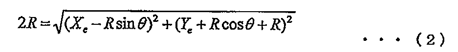
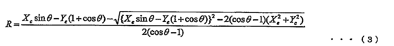

図13(a)に示す状態から図13(b)に示す交点F7の位置までが上記した計算式により算出可能である。
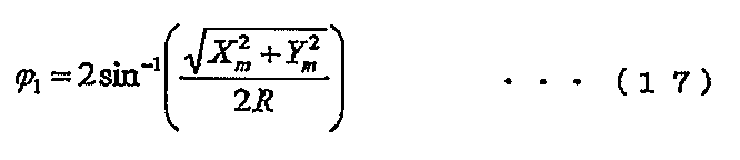
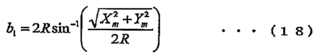
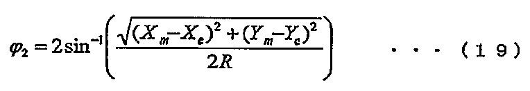
図13(c)に示す公式からS字のそれぞれの旋回角度φ1、φ2と、弧長b1、b2は以下の計算式により求められる。
図13(c)に示す公式からS字のそれぞれの旋回角度φ1、φ2と、弧長b1、b2は以下の計算式により求められる。
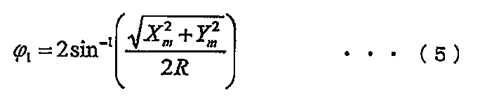


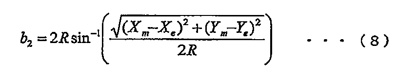
図14は、S字転舵による到達可能経路の生成方法を説明する図であり、接続候補位置Eよりも後方で軸線E2が現在位置Aの軸線A2であるX軸と交わる場合の生成方法を説明する図である。
ここでは、S字を描くための半径が同一となる共通の旋回円E1、A1の半径Rを算出する。そして、円の接点を求めれば、旋回円A1の円弧と、旋回円E1の円弧とを組み合わせてS字の到達可能経路を生成することができる。
共通円の半径はそれぞれの円の中心座標が求まるので、中心座標間の距離から求まる。
共通円の半径はそれぞれの円の中心座標が求まるので、中心座標間の距離から求まる。
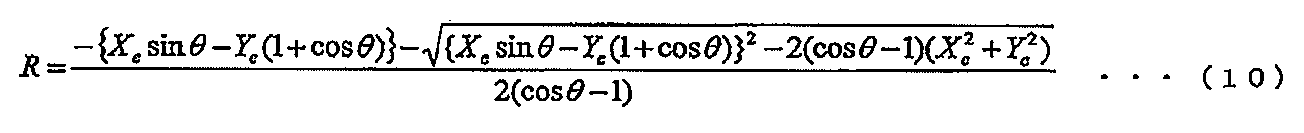
図13(c)に示す公式からS字のそれぞれの旋回角度φ1、φ2と、弧長b1、b2は以下の計算式により求められる。
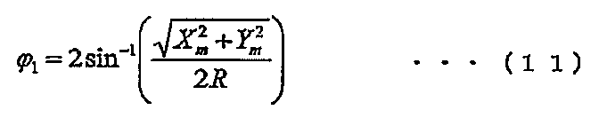


図15は、S字転舵による到達可能経路の生成方法を説明する図であり、接続候補位置Eよりも後方で軸線E2が現在位置Aの軸線A2であるX軸と交わる場合の生成方法を説明する図である。
ここでは、S字を描くための半径が同一となる共通円E1、A1の半径Rを算出する。そして、円の接点を求めれば、旋回円A1の円弧と、旋回円E1の円弧とを組み合わせてS字の到達可能経路を生成することができる。
共通円の半径はそれぞれの円の中心座標が求まるので、中心座標間の距離から求まる。


図13(c)に示す公式からS字のそれぞれの旋回角度φ1、φ2と、弧長b1、b2は以下の計算式により求められる。

<駐車経路設定部>
駐車経路設定部14は、目標駐車位置P1からパークアウト位置P2までの出庫経路の情報と、自車両Vの初期位置P0からパークアウト位置P2までの到達可能経路の情報を用いて駐車経路を設定する。駐車経路設定部14は、図10のステップS117で接続OKフラグをONにして生成された到達可能経路と、かかる到達可能経路が接続されているパークアウト位置P2を含む出庫経路とを繋いで駐車経路を形成する。
駐車経路設定部14は、目標駐車位置P1からパークアウト位置P2までの出庫経路の情報と、自車両Vの初期位置P0からパークアウト位置P2までの到達可能経路の情報を用いて駐車経路を設定する。駐車経路設定部14は、図10のステップS117で接続OKフラグをONにして生成された到達可能経路と、かかる到達可能経路が接続されているパークアウト位置P2を含む出庫経路とを繋いで駐車経路を形成する。
駐車経路は、複数設定できる場合に、駐車時間、後続車両の有無、駐車精度の高さ、通路の幅、または運転者の好みなど種々の評価値に応じて選択される。例えば駐車精度は、駐車スペースに曲がりながら進入するよりも、自車両Vの向きを駐車方位に合わせてから真っ直ぐに進入する方が精度が高い。したがって、駐車精度を優先する場合には、自車両の向きを駐車方位に合わせてから真っ直ぐに進入する駐車経路を選択する。
また、例えばパークアウト位置P2から駐車スペースに駐車する際に、前後の切り返しの回数や操舵量がなるべく少ない方が駐車に要する時間を短くすることができる。したがって、駐車に要する時間を短くする場合には、前後の切り返しの回数や操舵量がなるべく少なくなる駐車経路を選択する。
また、例えば駐車スペースから遠く離れた位置まで移動するよりも駐車スペースから離れない方が後続車両に駐車スペースへの駐車の意思を明確に示すことができる。したがって、通路上に後続車両が存在する場合には、駐車スペースから離れない駐車経路を選択する。
図5B、図6B、図7B、図8Bは、図5A、図6A、図7A、図8Aに示す複数の接続候補位置Pnから選択されたパークアウト位置P2を介して出庫経路と到達可能経路が繋げられた駐車経路を示す図である。
駐車経路50は、図5Bに示すように、パークアウト位置P2を介して出庫経路51と到達可能経路52を繋げることによって形成されており、パークアウト位置P2から曲がりながら後退して駐車スペース20に進入する経路となっている。駐車経路50の場合、パークアウト位置P2が駐車スペース20から大きく離れず、パークアウト位置P2から目標駐車位置P1まで自車両Vをスムーズに移動させることができる。したがって、駐車に要する時間を短くすることができる。
駐車経路60は、図6Bに示すように、パークアウト位置P2を介して出庫経路61と到達可能経路62を繋げることによって形成されており、パークアウト位置P2において自車両Vの向きが駐車方位26とほぼ一致する経路となっている。したがって、駐車経路60の場合、パークアウト位置P2からほぼ真っ直ぐに後退するだけで駐車スペース20に自車両Vを進入させることができ、目標駐車位置P1に高い精度で駐車することができる。
駐車経路70は、図7Bに示すように、パークアウト位置P2を介して出庫経路71と到達可能経路72を繋げることによって形成されている。出庫経路71は、目標駐車位置P1とパークアウト位置P2との間に到達可能限界位置P3が設けられている。そして、パークアウト位置P2における自車両Vの向きが通路31の通路方位と平行となるように設定されており、到達可能経路72は緩やかなS字となる。したがって、自車両Vの乗員に違和感を与えることなく、スムーズに目標駐車位置P1に駐車することができる。
駐車経路80は、図8Bに示すように、パークアウト位置P2を介して出庫経路81と到達可能経路82を繋げることによって形成されている。出庫経路81は、目標駐車位置P1とパークアウト位置P2との間に到達可能限界位置P3が設けられている。そして、パークアウト位置P2から到達可能限界位置P3までほぼ真っ直ぐに後退する経路となっている。したがって、かかる経路を移動する際の誤差を小さくすることができ、目標駐車位置P1に精度よく駐車することができる。
本発明によれば、目標駐車位置Bから出庫経路を演算し、出庫経路上に設定された複数の接続候補位置のうち、自車の現在位置Aから到達可能でかつ最も近い接続候補位置を接続候補位置Eとして選択し、目標駐車位置Bから接続候補位置Eまでの出庫経路と、自車両の現在位置Aから接続候補位置Eまでの到達可能経路とを用いて駐車経路を設定するので、駐車支援を開始する開始位置や車両姿勢に依存せずに、目標駐車位置Bに自車両Vを誘導するための切り返しを含む駐車経路を演算して、ドライバの意図する位置に正しい車両姿勢で車両を駐車させることができる。
以上、本発明の実施形態について詳述したが、本発明は、前記の実施形態に限定されるものではなく、請求の範囲に記載された本発明の精神を逸脱しない範囲で、種々の設計変更を行うことができるものである。例えば、前記した実施の形態は本発明を分かりやすく説明するために詳細に説明したものであり、必ずしも説明した全ての構成を備えるものに限定されるものではない。また、ある実施形態の構成の一部を他の実施形態の構成に置き換えることが可能であり、また、ある実施形態の構成に他の実施形態の構成を加えることも可能である。さらに、各実施形態の構成の一部について、他の構成の追加・削除・置換をすることが可能である。
1 駐車支援装置
11 出庫経路演算部
12 接続候補位置設定部
13 到達可能経路演算部
14 駐車経路設定部
15 操作入力部
16 経路表示部
20 駐車スペース
21、31 通路
22、23、24、32、33、34 障害物
25、35 通路方位
26、36 駐車方位
V 自車両
Vo 基準点
P0 初期位置
P1 目標駐車位置
P2 パークアウト位置
Pn 接続候補位置
11 出庫経路演算部
12 接続候補位置設定部
13 到達可能経路演算部
14 駐車経路設定部
15 操作入力部
16 経路表示部
20 駐車スペース
21、31 通路
22、23、24、32、33、34 障害物
25、35 通路方位
26、36 駐車方位
V 自車両
Vo 基準点
P0 初期位置
P1 目標駐車位置
P2 パークアウト位置
Pn 接続候補位置
Claims (3)
- 自車両の駐車スペースへの駐車を支援する駐車支援装置であって、
駐車空間の情報と自車挙動の制約条件に基づいて前記自車両を前記駐車スペースから出庫させる出庫経路を演算する出庫経路演算部と、
該出庫経路演算部により演算された出庫経路上に複数の接続候補位置を設定する接続候補位置設定部と、
前記自車両の現在位置から前記複数の接続候補位置のうちの一つに到達可能な到達可能経路を演算する到達可能経路演算部と、
前記出庫経路と前記到達可能経路とを繋げて駐車経路とする駐車経路設定部とを有し、 前記出庫経路演算部は、前記駐車が通路から該通路に対して斜めに配置された前記駐車スペースに前記自車両を駐車する斜め駐車である場合に、前記通路の通路方位と前記駐車スペースの駐車方位との間の傾斜角に基づいて前記出庫経路の演算を行うことを特徴とする駐車支援装置。 - 前記出庫経路演算部は、前記駐車スペースの駐車方位に対する前記出庫経路における前記自車両の向きが前記傾斜角以上となるまで前記出庫経路の演算を行うことを特徴とする請求項1に記載の駐車支援装置。
- 前記接続候補位置設定部は、
前記自車両を前記出庫経路に沿って出庫する方向に移動させた場合に前記自車両の向きが所定の相対指定角度分だけ変化する位置を前記接続候補位置として設定することを特徴とする請求項2に記載の駐車支援装置。
Priority Applications (3)
| Application Number | Priority Date | Filing Date | Title |
|---|---|---|---|
| EP18781334.0A EP3608189B1 (en) | 2017-04-07 | 2018-04-03 | Parking assistance device |
| CN201880023760.0A CN110494336B (zh) | 2017-04-07 | 2018-04-03 | 停车辅助装置 |
| US16/603,490 US11293764B2 (en) | 2017-04-07 | 2018-04-03 | Parking assistance device |
Applications Claiming Priority (2)
| Application Number | Priority Date | Filing Date | Title |
|---|---|---|---|
| JP2017-077170 | 2017-04-07 | ||
| JP2017077170A JP7002210B2 (ja) | 2017-04-07 | 2017-04-07 | 駐車支援装置 |
Publications (1)
| Publication Number | Publication Date |
|---|---|
| WO2018186406A1 true WO2018186406A1 (ja) | 2018-10-11 |
Family
ID=63713454
Family Applications (1)
| Application Number | Title | Priority Date | Filing Date |
|---|---|---|---|
| PCT/JP2018/014290 WO2018186406A1 (ja) | 2017-04-07 | 2018-04-03 | 駐車支援装置 |
Country Status (5)
| Country | Link |
|---|---|
| US (1) | US11293764B2 (ja) |
| EP (1) | EP3608189B1 (ja) |
| JP (1) | JP7002210B2 (ja) |
| CN (1) | CN110494336B (ja) |
| WO (1) | WO2018186406A1 (ja) |
Cited By (4)
| Publication number | Priority date | Publication date | Assignee | Title |
|---|---|---|---|---|
| EP3421328A1 (en) * | 2017-05-30 | 2019-01-02 | LG Electronics Inc. | Parking assistance system |
| CN111063211A (zh) * | 2018-10-16 | 2020-04-24 | 现代自动车株式会社 | 车辆停车辅助设备和方法 |
| JP2020152348A (ja) * | 2019-03-22 | 2020-09-24 | 株式会社Jvcケンウッド | 駐車支援制御装置、駐車支援装置、駐車支援方法およびプログラム |
| KR102703729B1 (ko) * | 2018-10-16 | 2024-09-09 | 현대자동차주식회사 | 차량의 주차 지원 장치 및 방법 |
Families Citing this family (12)
| Publication number | Priority date | Publication date | Assignee | Title |
|---|---|---|---|---|
| JP2020152347A (ja) * | 2019-03-22 | 2020-09-24 | 株式会社Jvcケンウッド | 駐車支援制御装置、駐車支援装置、駐車支援方法およびプログラム |
| DE102019204656A1 (de) * | 2019-04-02 | 2020-10-08 | Conti Temic Microelectronic Gmbh | Parkassistenzsystem |
| JP7363343B2 (ja) * | 2019-10-11 | 2023-10-18 | 株式会社アイシン | 駐車支援装置、駐車支援方法、および、駐車支援プログラム |
| JP7069239B2 (ja) | 2020-03-18 | 2022-05-17 | 本田技研工業株式会社 | 駐車支援システム |
| JP7508888B2 (ja) | 2020-06-19 | 2024-07-02 | 株式会社アイシン | 通路方向検出装置 |
| CN111731275B (zh) * | 2020-06-30 | 2021-12-07 | 中国第一汽车股份有限公司 | 空间斜向车位自动泊车方法、装置、车辆及存储介质 |
| CN111746525B (zh) * | 2020-07-07 | 2022-06-21 | 东风柳州汽车有限公司 | 泊车路径规划方法、装置、设备及存储介质 |
| CN112677959A (zh) * | 2020-12-23 | 2021-04-20 | 广州小鹏自动驾驶科技有限公司 | 一种泊车的方法和装置 |
| CN113085840B (zh) * | 2021-04-21 | 2023-03-07 | 中国第一汽车股份有限公司 | 一种泊车路径的确定方法、装置、车辆及存储介质 |
| US11860628B2 (en) * | 2021-06-21 | 2024-01-02 | Nvidia Corporation | Parallel processing of vehicle path planning suitable for parking |
| JP7473087B2 (ja) | 2021-09-29 | 2024-04-23 | 株式会社デンソー | 駐車支援装置、駐車支援方法 |
| EP4289702A1 (en) * | 2022-06-07 | 2023-12-13 | Valeo Internal Automotive Software Egypt, a limited liability company | Method to operate an at least assisted perpendicular or angled parking function for a vehicle |
Citations (8)
| Publication number | Priority date | Publication date | Assignee | Title |
|---|---|---|---|---|
| JP2007320433A (ja) * | 2006-05-31 | 2007-12-13 | Aisin Aw Co Ltd | 駐車案内装置 |
| JP2008207732A (ja) * | 2007-02-27 | 2008-09-11 | Denso Corp | 運転支援装置 |
| JP2010208392A (ja) | 2009-03-09 | 2010-09-24 | Nissan Motor Co Ltd | 駐車支援装置及び駐車支援方法 |
| JP2013500902A (ja) * | 2009-08-05 | 2013-01-10 | ローベルト ボツシユ ゲゼルシヤフト ミツト ベシユレンクテル ハフツング | パーキングスペースへの駐車支援方法及び駐車支援装置 |
| WO2013072134A1 (de) * | 2011-11-14 | 2013-05-23 | Robert Bosch Gmbh | Verfahren und vorrichtung zum bestimmen einer ausparkstrategie |
| JP2014141175A (ja) * | 2013-01-24 | 2014-08-07 | Daihatsu Motor Co Ltd | 車両制御装置 |
| JP2015074253A (ja) * | 2013-10-04 | 2015-04-20 | アイシン精機株式会社 | 駐車支援装置 |
| WO2018003411A1 (ja) * | 2016-07-01 | 2018-01-04 | クラリオン株式会社 | 駐車支援装置 |
Family Cites Families (3)
| Publication number | Priority date | Publication date | Assignee | Title |
|---|---|---|---|---|
| JP5737061B2 (ja) * | 2011-08-23 | 2015-06-17 | 日産自動車株式会社 | 駐車モード選択装置 |
| KR101498973B1 (ko) * | 2013-11-21 | 2015-03-05 | 현대모비스(주) | 차량용 주차 지원 시스템 및 방법 |
| JP2016016681A (ja) * | 2014-07-04 | 2016-02-01 | クラリオン株式会社 | 駐車枠認識装置 |
-
2017
- 2017-04-07 JP JP2017077170A patent/JP7002210B2/ja active Active
-
2018
- 2018-04-03 US US16/603,490 patent/US11293764B2/en active Active
- 2018-04-03 EP EP18781334.0A patent/EP3608189B1/en active Active
- 2018-04-03 CN CN201880023760.0A patent/CN110494336B/zh active Active
- 2018-04-03 WO PCT/JP2018/014290 patent/WO2018186406A1/ja active Application Filing
Patent Citations (8)
| Publication number | Priority date | Publication date | Assignee | Title |
|---|---|---|---|---|
| JP2007320433A (ja) * | 2006-05-31 | 2007-12-13 | Aisin Aw Co Ltd | 駐車案内装置 |
| JP2008207732A (ja) * | 2007-02-27 | 2008-09-11 | Denso Corp | 運転支援装置 |
| JP2010208392A (ja) | 2009-03-09 | 2010-09-24 | Nissan Motor Co Ltd | 駐車支援装置及び駐車支援方法 |
| JP2013500902A (ja) * | 2009-08-05 | 2013-01-10 | ローベルト ボツシユ ゲゼルシヤフト ミツト ベシユレンクテル ハフツング | パーキングスペースへの駐車支援方法及び駐車支援装置 |
| WO2013072134A1 (de) * | 2011-11-14 | 2013-05-23 | Robert Bosch Gmbh | Verfahren und vorrichtung zum bestimmen einer ausparkstrategie |
| JP2014141175A (ja) * | 2013-01-24 | 2014-08-07 | Daihatsu Motor Co Ltd | 車両制御装置 |
| JP2015074253A (ja) * | 2013-10-04 | 2015-04-20 | アイシン精機株式会社 | 駐車支援装置 |
| WO2018003411A1 (ja) * | 2016-07-01 | 2018-01-04 | クラリオン株式会社 | 駐車支援装置 |
Non-Patent Citations (1)
| Title |
|---|
| See also references of EP3608189A4 |
Cited By (6)
| Publication number | Priority date | Publication date | Assignee | Title |
|---|---|---|---|---|
| EP3421328A1 (en) * | 2017-05-30 | 2019-01-02 | LG Electronics Inc. | Parking assistance system |
| US10583829B2 (en) | 2017-05-30 | 2020-03-10 | Lg Electronics Inc. | Parking assistance system |
| CN111063211A (zh) * | 2018-10-16 | 2020-04-24 | 现代自动车株式会社 | 车辆停车辅助设备和方法 |
| KR102703729B1 (ko) * | 2018-10-16 | 2024-09-09 | 현대자동차주식회사 | 차량의 주차 지원 장치 및 방법 |
| JP2020152348A (ja) * | 2019-03-22 | 2020-09-24 | 株式会社Jvcケンウッド | 駐車支援制御装置、駐車支援装置、駐車支援方法およびプログラム |
| JP7208460B2 (ja) | 2019-03-22 | 2023-01-19 | 株式会社Jvcケンウッド | 駐車支援制御装置、駐車支援装置、駐車支援方法およびプログラム |
Also Published As
| Publication number | Publication date |
|---|---|
| JP2018176910A (ja) | 2018-11-15 |
| JP7002210B2 (ja) | 2022-01-20 |
| CN110494336A (zh) | 2019-11-22 |
| EP3608189A1 (en) | 2020-02-12 |
| US20200041287A1 (en) | 2020-02-06 |
| EP3608189B1 (en) | 2022-02-23 |
| CN110494336B (zh) | 2022-09-09 |
| US11293764B2 (en) | 2022-04-05 |
| EP3608189A4 (en) | 2021-01-06 |
Similar Documents
| Publication | Publication Date | Title |
|---|---|---|
| WO2018186406A1 (ja) | 駐車支援装置 | |
| CN110214097B (zh) | 驻车辅助装置 | |
| JP6722616B2 (ja) | 駐車支援装置 | |
| JP6989333B2 (ja) | 駐車支援装置 | |
| CN110494345B (zh) | 停车辅助装置 | |
| WO2018186253A1 (ja) | 駐車支援装置 | |
| CN109311443B (zh) | 停车辅助装置 | |
| CN111071247B (zh) | 自动驾驶控制装置以及自动驾驶路径运算方法 | |
| JP6751191B2 (ja) | 駐車支援装置 |
Legal Events
| Date | Code | Title | Description |
|---|---|---|---|
| 121 | Ep: the epo has been informed by wipo that ep was designated in this application |
Ref document number: 18781334 Country of ref document: EP Kind code of ref document: A1 |
|
| NENP | Non-entry into the national phase |
Ref country code: DE |
|
| WWE | Wipo information: entry into national phase |
Ref document number: 2018781334 Country of ref document: EP |
|
| ENP | Entry into the national phase |
Ref document number: 2018781334 Country of ref document: EP Effective date: 20191107 |