WO2018186254A1 - 粘着テープの製造方法 - Google Patents
粘着テープの製造方法 Download PDFInfo
- Publication number
- WO2018186254A1 WO2018186254A1 PCT/JP2018/012722 JP2018012722W WO2018186254A1 WO 2018186254 A1 WO2018186254 A1 WO 2018186254A1 JP 2018012722 W JP2018012722 W JP 2018012722W WO 2018186254 A1 WO2018186254 A1 WO 2018186254A1
- Authority
- WO
- WIPO (PCT)
- Prior art keywords
- sensitive adhesive
- base
- pressure
- adhesive layer
- surface layer
- Prior art date
- Legal status (The legal status is an assumption and is not a legal conclusion. Google has not performed a legal analysis and makes no representation as to the accuracy of the status listed.)
- Ceased
Links
Images


Classifications
-
- C—CHEMISTRY; METALLURGY
- C09—DYES; PAINTS; POLISHES; NATURAL RESINS; ADHESIVES; COMPOSITIONS NOT OTHERWISE PROVIDED FOR; APPLICATIONS OF MATERIALS NOT OTHERWISE PROVIDED FOR
- C09J—ADHESIVES; NON-MECHANICAL ASPECTS OF ADHESIVE PROCESSES IN GENERAL; ADHESIVE PROCESSES NOT PROVIDED FOR ELSEWHERE; USE OF MATERIALS AS ADHESIVES
- C09J7/00—Adhesives in the form of films or foils
- C09J7/10—Adhesives in the form of films or foils without carriers
-
- C—CHEMISTRY; METALLURGY
- C09—DYES; PAINTS; POLISHES; NATURAL RESINS; ADHESIVES; COMPOSITIONS NOT OTHERWISE PROVIDED FOR; APPLICATIONS OF MATERIALS NOT OTHERWISE PROVIDED FOR
- C09J—ADHESIVES; NON-MECHANICAL ASPECTS OF ADHESIVE PROCESSES IN GENERAL; ADHESIVE PROCESSES NOT PROVIDED FOR ELSEWHERE; USE OF MATERIALS AS ADHESIVES
- C09J7/00—Adhesives in the form of films or foils
- C09J7/30—Adhesives in the form of films or foils characterised by the adhesive composition
- C09J7/38—Pressure-sensitive adhesives [PSA]
Definitions
- the present invention relates to a method for producing an adhesive tape.
- a pressure-sensitive adhesive (also referred to as a pressure-sensitive adhesive; the same shall apply hereinafter) is in the form of a soft solid (viscoelastic body) in a temperature range near room temperature and has a property of easily adhering to an adherend by pressure. Taking advantage of such properties, pressure-sensitive adhesives are typically used in the form of pressure-sensitive adhesive tapes, for example, for purposes such as fixing various items, surface protection, or obtaining a desired appearance such as decoration.
- Adhesive tape is required to have various characteristics depending on the application. Moreover, even if it is the same kind of characteristic, the level of the characteristic (for example, strength of adhesive force) required by the use purpose and usage mode of an adhesive tape may differ. Accordingly, various proposals have been made to improve or adjust the characteristics of the adhesive tape.
- the mainstream of such proposals is related to the composition of the pressure-sensitive adhesive, and specific examples include Patent Documents 1 to 3.
- the present invention has been made in view of such a situation, and an object of the present invention is to provide a method for rapidly producing an adhesive tape exhibiting an adhesive force adjusted according to a target.
- the manufacturing method includes preparing a base pressure-sensitive adhesive layer group including n types of base pressure-sensitive adhesive layers.
- the base pressure-sensitive adhesive layer has a known adhesive force N B.
- N is an integer satisfying n ⁇ 1. when n is 2 or greater, the base pressure-sensitive adhesive layer group is prepared as the adhesive force N B is contained to at least two different base pressure-sensitive adhesive layer to each other.
- the manufacturing method also includes preparing a surface layer material pattern group including m types of surface layer material patterns.
- the surface layer material pattern by a surface layer material having a known adhesion N C is configured so as to cover the base pressure-sensitive adhesive layer in a known area coverage X in the range 0 ⁇ X ⁇ 1 of ing.
- M is an integer that satisfies m ⁇ 1 and n + m ⁇ 3. when m is 2 or more, the surface layer material pattern group is prepared as at least one of the adhesion N C and the coating area ratio X is included for at least two different surface material pattern with each other.
- the base pressure-sensitive adhesive is further bonded to a base pressure-sensitive adhesive layer selected from the base pressure-sensitive adhesive layer group by attaching one or more surface layer material patterns selected from the surface layer material pattern group.
- the base pressure-sensitive adhesive layer and the surface layer material pattern is selected to design the adhesive force N A that is calculated by the following equation (1) approaches the target adhesion N T.
- N A ((N C ⁇ N B ) ⁇ X) + N B (1)
- the adjustment of the adhesive force is performed substantially uniformly in each part of the base adhesive layer.
- the uniformity of adhesive force adjustment can be evaluated by, for example, the magnitude of the fluctuation range of the peel strength in a 90-degree peel test performed at a pulling speed of 300 mm / min.
- the base pressure-sensitive adhesive layer and the surface layer material pattern are selected so that a pressure-sensitive adhesive tape having a variation range of the peel strength of 5 N / 20 mm or less is formed. can do.
- the pressure-sensitive adhesive tape having a small fluctuation range is preferable because it can provide a smooth response to the user and a good feeling of use.
- At least a part of the m kinds of surface layer material patterns may be prepared in the form of a surface layer material transfer sheet including a base material having a release surface and a surface layer material pattern supported on the release surface of the base material. .
- a surface layer material transfer sheet including a base material having a release surface and a surface layer material pattern supported on the release surface of the base material.
- the storage property and handleability of the surface layer material pattern are good. Further, by using the surface layer material transfer sheet, the operation of bonding the surface layer material pattern to the base pressure-sensitive adhesive layer can be performed efficiently.
- At least a part of the m types of surface layer material patterns may be in the form of a surface layer material transfer sheet roll on which the surface layer material transfer sheet is wound.
- a sheet for transferring a surface layer material in a roll form is preferable because it has good storage stability and handleability.
- At least a part of the n types of base pressure-sensitive adhesive layers can be prepared in the form of a base pressure-sensitive adhesive tape including a base material and the base pressure-sensitive adhesive layer supported by the base material, for example.
- a base pressure-sensitive adhesive tape including a base material and the base pressure-sensitive adhesive layer supported by the base material, for example.
- the storage stability and handleability of the base adhesive layer are good.
- the operation which bonds a surface material pattern to a base adhesive layer can be performed efficiently.
- At least a part of the n types of base adhesive layers may be in the form of a base adhesive tape roll in which the base adhesive tape is wound in a spiral shape.
- a base adhesive tape in the form of a roll is preferable because of its good storage stability and handleability.
- both the base adhesive tape and the surface layer material transfer sheet in a roll form both can be continuously unwound from the roll form and bonded together efficiently. This can contribute to the productivity improvement of the adhesive tape.
- the base adhesive layer has a ratio (N B / N T ) of the adhesive strength N B of the base adhesive layer to the target adhesive strength N T of 0.5 to 0.9 or 1. It is preferable to select 1 to 1.5. That is, it is preferable to select a base adhesive layer having a known adhesive strength N B that is 10% to 50% higher or 10% to 50% lower than the target adhesive strength NT .
- the method disclosed here can be suitably implemented in a mode in which a surface layer material pattern is bonded to the base pressure-sensitive adhesive layer thus selected.
- the thickness of the base pressure-sensitive adhesive layer selected from the group of base pressure-sensitive adhesive layers is preferably 20 ⁇ m or more. Since the base pressure-sensitive adhesive layer having such a thickness tends to be more deformable than a thinner base pressure-sensitive adhesive layer, it is easy to improve the adhesion between the base pressure-sensitive adhesive layer and the surface layer material. This can be advantageous from the viewpoint of suppressing the fluctuation range of the peel strength.
- the surface material pattern selected from the surface material pattern group is preferably non-adhesive in the surface material constituting the surface material pattern.
- a surface layer material pattern composed of a non-adhesive surface layer material can be advantageous from the viewpoints of handling of the surface layer material pattern and operability when the surface layer material pattern is bonded to the base adhesive layer.
- the surface layer material pattern selected from the above surface layer material pattern group preferably has a thickness of the surface layer material constituting the surface layer material pattern of 5 ⁇ m or less. Since such a surface layer material is easy to adjust to the base pressure-sensitive adhesive layer, it is easy to suppress the fluctuation range of the peel strength.
- the outer shape and arrangement of the surface layer material constituting the surface layer material pattern are not particularly limited.
- the surface layer material pattern is preferably composed of the dot-shaped surface layer material arranged in a dispersed manner.
- the covering area ratio X can be easily varied by varying the size and dispersion density (number of dots per unit area) of the dots. Therefore, a surface layer material pattern group including a plurality of types of surface layer material patterns having different covering area ratios X can be efficiently prepared. Producing an adhesive tape using such a surface layer material pattern is also preferable from the viewpoint of suppressing the peel strength fluctuation range and improving the sealing property.
- the base pressure-sensitive adhesive layer selected from the base pressure-sensitive adhesive layer group includes a base material on which both the first surface and the second surface are non-peelable, and the first surface of the base material. It may be the first pressure-sensitive adhesive layer constituting a double-sided pressure-sensitive adhesive tape with a substrate having a supported first pressure-sensitive adhesive layer and a second pressure-sensitive adhesive layer supported on the second surface of the substrate. By bonding the surface layer material pattern to the first pressure-sensitive adhesive layer (base pressure-sensitive adhesive layer), a double-sided pressure-sensitive adhesive tape with a substrate in which the pressure-sensitive adhesive force on the first pressure-sensitive adhesive layer side is accurately adjusted can be produced. .
- the second pressure-sensitive adhesive layer side of the double-sided pressure-sensitive adhesive tape has a surface layer material pattern applied to the second pressure-sensitive adhesive layer. It may be configured to show the original adhesive strength of the second pressure-sensitive adhesive layer without matching, and a surface material pattern of the same or different type as the first pressure-sensitive adhesive layer may be bonded to the second pressure-sensitive adhesive layer.
- the pressure-sensitive adhesive tape manufacturing method disclosed herein can be carried out, for example, in such a manner that the surface layer material pattern is bonded only to the first pressure-sensitive adhesive layer and the surface layer material pattern is not bonded to the second pressure-sensitive adhesive layer.
- the balance of the adhesive force between the first surface and the second surface of the double-sided pressure-sensitive adhesive tape can be easily adjusted.
- Such an embodiment can be preferably employed as a method for producing a double-sided pressure-sensitive adhesive tape with a substrate having different adhesive strengths on the first pressure-sensitive adhesive layer side and the second pressure-sensitive adhesive layer side, for example.
- the base pressure-sensitive adhesive layer selected from the group of base pressure-sensitive adhesive layers may be a substrate-less double-sided pressure-sensitive adhesive tape composed of a pressure-sensitive adhesive layer having a single layer structure.
- the other surface (second surface) side of the double-sided pressure-sensitive adhesive tape is
- the base pressure-sensitive adhesive layer may be configured so as to exhibit the original adhesive strength without bonding the surface layer material pattern to the base pressure-sensitive adhesive layer. You may stick together.
- the pressure-sensitive adhesive tape manufacturing method disclosed herein is suitably implemented, for example, in such a manner that the surface layer material pattern is bonded only to the first surface of the base material-less double-sided pressure-sensitive adhesive tape and the surface layer material pattern is not bonded to the second surface. be able to.
- the balance of the adhesive force between the first surface side and the second surface side of the pressure-sensitive adhesive layer having a single layer structure can be easily adjusted.
- Such an embodiment can be preferably employed, for example, as a method for producing a baseless double-sided pressure-sensitive adhesive tape having different adhesive strengths on the first surface side and the second surface side.
- an adhesive tape manufactured by any of the methods disclosed herein is also provided.
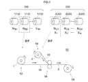
- FIG. 1 is an explanatory view showing the adhesive tape manufacturing method concerning one embodiment.
- FIG. 2 is an explanatory diagram showing an example of a base adhesive layer prepared in the form of a base adhesive tape roll.
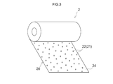
- FIG. 3 is an explanatory diagram illustrating an example of a surface layer material pattern prepared in the form of a surface layer material transfer sheet roll.
- FIG. 4 is an explanatory view showing another example of a base adhesive layer prepared in the form of a base adhesive tape roll.
- the present embodiment is an example of one embodiment relating to the production of a single-sided pressure-sensitive adhesive tape with a substrate using the method disclosed herein.
- a base pressure-sensitive adhesive layer group 100 including n types of base pressure-sensitive adhesive layers 12 is prepared (step S10).
- each base pressure-sensitive adhesive layer 12 constitutes a base pressure-sensitive adhesive tape 10 in which the base pressure-sensitive adhesive layer 12 is supported by a non-peelable substrate 14.
- the adhesive tape 10 may be in the form of a base adhesive tape roll 1 wound in the longitudinal direction.
- Adhesive force N B of each base adhesive layer 12 contained in the base adhesive layer group 100 is known.
- N B1, N B2 ⁇ N Bn shown in FIG. 1 represents a first type, second type ⁇ ⁇ ⁇ n type th adhesion N B of the base adhesive layer 12.
- a surface layer material pattern group 200 including m types of surface layer material patterns 22 is prepared (step S20).
- each surface layer material pattern 22 constitutes a surface layer material transfer sheet 20 in which the surface layer material pattern 22 constituted by the surface layer material 21 is provided on the peeling surface 24 ⁇ / b> A of the elongated base material 24. is doing.
- the surface layer material transfer sheet 20 may be in the form of a surface layer material transfer sheet roll 2 wound in the longitudinal direction.
- Area coverage X of adhesion N C and said surface layer material pattern 22 of surface layer material 21 constituting the respective surface layer material pattern 22 included in the surface layer material pattern group 200 is known.
- NCm and X 1 , X 2 ... X m shown in FIG. 1 are the surface layers constituting the surface material patterns 22 of the first type, the second type, and the m type. it represents the area coverage X of adhesion N C and said surface layer material pattern 22 of the timber.
- each of the base adhesive layer 12 and the surface layer material pattern 22 is selected from the base adhesive layer group 100 and the surface layer material pattern group 200 (step S30).
- This selection is designed adhesive force N A that is calculated by the following equation (1) is performed to be close to target adhesion N T which is set in advance.
- FIG. 1 shows an example in which a base pressure-sensitive adhesive layer 12 having an adhesive strength N B2 and a surface layer material pattern 22 having an adhesive strength N C1 and a covering area ratio X 1 are selected.
- N A ((N C ⁇ N B ) ⁇ X) + N B (1)
- the target adhesive strength NT means an adhesive strength desired for the adhesive tape to be manufactured.
- the target adhesive force NT can be determined in view of, for example, the purpose of use or usage of the adhesive tape to be manufactured. Or you may determine the target adhesive force NT according to a user's request.
- the target adhesion N T is the target adhesion N T, as compared to the absolute value of the difference between the adhesive force N B and the target adhesion N T of the base adhesive layer, designed adhesion N A and the target It means that the absolute value of the difference from the adhesive strength NT becomes smaller. Therefore, in step S30, the base pressure-sensitive adhesive layer and the surface material pattern may be selected so as to satisfy the following formula (2).
- Step S40 the selected surface material pattern 22 is bonded to the base adhesive layer 12 selected in Step S30 (Step S40).
- This step can be performed using, for example, a bonding apparatus 50 having a schematic configuration schematically shown in FIG.
- the bonding apparatus 50 is an apparatus having a function of bonding at least the base adhesive layer 12 and the surface layer material pattern 22.
- the base adhesive tape supply unit 52 and the surface layer material transfer sheet are used.
- a supply unit 54, a bonding unit 56, and a winding unit 58 are provided.
- the base adhesive tape roll 1 and the surface layer material transfer sheet roll 2 selected in step S30 are set on the base adhesive tape supply unit 52 and the surface layer material transfer sheet supply unit 54, respectively.
- the base adhesive tape 10 and the surface layer material transfer sheet 20 that are continuously unwound from the rolls 1 and 2 are superposed and pressure-bonded by a bonding portion 56.
- the surface layer material pattern 22 is transferred to the base pressure-sensitive adhesive layer 12, and the pressure-sensitive adhesive tape 3 having the structure in which the base pressure-sensitive adhesive layer 12 is partially covered with the surface layer material 21 is formed.
- the peelable substrate 24 constituting the surface layer material transfer sheet 20 is wound together with the adhesive tape 3.
- the peelable base material 24 used for supporting and transferring the surface layer material pattern 22 can be effectively used as a release liner for protecting the surface (adhesive surface) of the adhesive tape 3.
- the pressure-sensitive adhesive tape 3 whose pressure-sensitive adhesive surface is protected by the peelable substrate (release liner) 24 can be grasped as a constituent element of the pressure-sensitive adhesive tape with a release liner including the pressure-sensitive adhesive tape 3 and the release liner 24.
- the adhesive tape 3 can be used as a final product as it is.
- the adhesive tape 3 may be a final product that is further subjected to post-processing such as rewinding, slitting, cutting, and the like.
- the adhesive tape 3 may be generally called a jumbo roll or a log roll. Good.
- the base adhesive layer group 100 is preferably provided as the adhesive force N B comprises of at least two different base adhesive layer 12 from each other. Some base adhesive layer group 100 will vary the same adhesive strength N B, composition, structure (e.g., thickness), or characteristics (e.g., optical characteristics, deterioration preventive properties, volatile organic compound content, etc.) to each other A base adhesive layer 12 may be included. Further, in the base adhesive layer group 100, the types (for example, material, thickness, optical characteristics, presence / absence or type of surface treatment, porosity, etc.) of the base material 14 that supports the base adhesive layer 12 are different from each other. adhesive force N B may contain the same or different base pressure-sensitive adhesive layer 12.
- Surface layer material pattern group 200 is preferably provided so that at least one pressure-sensitive adhesive force N C and area coverage X comprises of at least two different surface material pattern 22 to each other. Some of the surface layer material pattern group 200, a adhesion N C and area coverage X is the same, the composition may or characteristic contains different surface material pattern 22 to each other. Also, some of the surface material pattern group 200, the type of substrate 24 for supporting the surface layer material pattern 22 (e.g., material, thickness, release properties, etc.) are different from each other, adhesion N C and area coverage X is either identical Alternatively, different surface layer material patterns 22 may be included.
- the covering area ratio X of the surface layer material pattern is defined as the ratio of the area where the surface layer material exists in the surface layer material pattern of the unit area. For example, in a surface layer material pattern in which 15 surface layer materials having a dot shape (for example, 1 mm square shape) having an area of 1 mm 2 are dispersed in a 10 mm square area, the coverage area ratio X is calculated to be 15%. Is done.
- the covering area ratio X can be grasped by observing the surface material pattern visually or with a microscope. The microscope observation can be performed at an appropriate magnification selected from a range of about 10 to 1000 times, for example.
- Adhesive strengths N B and N C are in accordance with JIS Z0237: 2000, and are bonded to a stainless steel plate (SUS304BA plate) as an adherend in an environment of 23 ° C., and 30 minutes later, a pulling speed of 300 mm / min and a peeling angle of 180 It can be grasped in advance as a measured value (180 degree peeling adhesive strength) obtained by performing a peeling test under the condition of degree.
- Adhesion N C of the surface layer material can be surface layer material carried out using a test piece provided on the entire surface.
- a measurement value obtained using a test piece (for example, a test piece having a covering area ratio X) partially provided with a surface layer material is used as an area where the surface layer material is provided in the test piece. You may convert into a win value.
- the width of the test piece used for the measurement is desirably 15 mm to 30 mm. For example, a 20 mm strip-shaped test piece may be used.
- the pressure bonding may be performed under a condition in which a 2 kg roller is reciprocated once or a condition corresponding thereto. It is desirable to perform the measurement three or more times for each type, and adopt an average value thereof.
- the peel test can be performed using a commercially available tensile tester (for example, a universal tensile / compression tester “TG-1kN” manufactured by Minebea).
- a commercially available tensile tester for example, a universal tensile / compression tester “TG-1kN” manufactured by Minebea.
- an appropriate backing material for example, a polyester film having a thickness of about 50 ⁇ m
- Adhesion N C of the surface layer material may be substantially zero.
- the surface layer material having no tack (stickiness) when touched with a finger at 23 ° C. the surface layer material adhesion N C is substantially zero, i.e. can be evaluated as a non-tacky surface layer material. In such a case, it is possible to grasp the adhesion N C of surface layer material without performing the peel test.
- the non-peelable base material 14 is used as the base material constituting the base pressure-sensitive adhesive tape 10, but the base material that supports the base pressure-sensitive adhesive layer 12 in the base pressure-sensitive adhesive tape 10 is shown in FIG. As shown, a peelable substrate 15 may be used. According to this embodiment, the base adhesive is bonded to the base-less base adhesive layer 12 provided on the peelable substrate 15 by bonding the surface layer material pattern 22 provided on the peelable substrate 24. The pressure-sensitive adhesive tape 3 in which one surface 12A of the layer 12 is partially covered with the surface layer material is formed.
- the pressure-sensitive adhesive tape 3 can be grasped as a double-sided pressure-sensitive adhesive tape in which the other surface 12B of the base-less base pressure-sensitive adhesive layer 12 is protected by a peelable base material 15. That is, a baseless double-sided pressure-sensitive adhesive tape can be suitably manufactured by changing the non-peelable base material 14 constituting the base pressure-sensitive adhesive tape 10 to the peelable base material 15 in the first embodiment.
- Adhesive tape 3 obtained by this embodiment the adhesive force N B in the one surface 12A of the base adhesive layer 12 is adjusted so as to approach the target adhesion N T by the surface layer member 21, the other base adhesive layer 12 surface 12B may be configured as a substrate-less double-sided pressure-sensitive adhesive tape showing the original adhesive force N B of.
- the surface layer material pattern 22 is bonded to one surface of a base-less base pressure-sensitive adhesive layer (typically a single-layer pressure-sensitive adhesive layer) in which one surface and the other surface exhibit similar adhesive strength.
- a highly functional baseless double-sided pressure-sensitive adhesive tape in which the adhesive force is different between the one surface side and the other surface side can be produced.
- a similar effect can also be realized by bonding different surface layer material patterns 22 (for example, different covering area ratios X) to one surface and the other surface of the base pressure-sensitive adhesive layer 12.
- This embodiment is an example relating to the production of a double-sided pressure-sensitive adhesive tape with a substrate using the method disclosed herein.
- the first pressure-sensitive adhesive layer 41 and the second pressure-sensitive adhesive layer 42 are provided on the first surface 44 ⁇ / b> A and the second surface 44 ⁇ / b> B (both non-peeling surfaces) of the base material 44.
- the double-sided pressure-sensitive adhesive tape 40 with the base material having the structure is used as a base pressure-sensitive adhesive tape, and the first pressure-sensitive adhesive layer 41 is a base pressure-sensitive adhesive layer.
- the double-sided pressure-sensitive adhesive with the base material adjusted so that the pressure-sensitive adhesive force of the first pressure-sensitive adhesive layer (base pressure-sensitive adhesive layer) 41 approaches the target pressure-sensitive adhesive strength NT in substantially the same manner as in the first embodiment described above. Tape can be obtained.
- the first pressure-sensitive adhesive layer side of the adhesive force N B and the double-sided adhesive tape with the second and adhesion N D of the pressure-sensitive adhesive layer side is comparable substrate as a base pressure-sensitive adhesive tape
- the first pressure-sensitive adhesive layer partially adhesion N B of the first pressure-sensitive adhesive layer side was adjusted so as to approach the target adhesion N T by covering the surface layer material
- the second pressure-sensitive adhesive layer side of the original with the configuration as shown adhesion N D it is possible to efficiently produce a double-sided adhesive tape with sophisticated substrates having different adhesive strength between the first pressure-sensitive adhesive layer side and a second pressure-sensitive adhesive layer side it can.
- the double-sided adhesive tape 40 with a base material used as a base adhesive tape is in the form of a base adhesive tape roll 4 wound in a roll with a release liner 46 whose both surfaces are release surfaces. It can be.
- the double-sided pressure-sensitive adhesive tape 40 with the base material is not limited to one in which the first pressure-sensitive adhesive layer 41 and the second pressure-sensitive adhesive layer 42 exhibit the same level of adhesive strength, and may exhibit different adhesive strengths.
- the 1st adhesive layer 41 and the 2nd adhesive layer 42 may be the same structures, for example, may differ in points, such as a composition and thickness.
- the significance of different adhesive forces between one side and the other side of a double-sided pressure-sensitive adhesive tape with or without a base material is, for example, the double-sided surface.
- the double-sided pressure-sensitive adhesive tape can be selectively left on one of the one object and the other object by making the adhesive force different between one side and the other side of the double-sided pressure-sensitive adhesive tape. it can.
- the one object and the other object may be two or more separate articles or members, or may be different places in one article or one member.
- the number n of types of the base pressure-sensitive adhesive layers contained in the base pressure-sensitive adhesive layer group is at least 1, usually 2 or higher, 3 or higher is preferable, 5 or higher, or 10 or higher.
- the base pressure-sensitive adhesive layer group is prepared so as to include two or more types of base pressure-sensitive adhesive layers.
- the upper limit of the number of types n is not particularly limited. In some aspects, the number n of types may be, for example, 500 or less, 100 or less, 50 or less, or 20 or less in consideration of practicality such as ease of inventory management and storage space saving. But you can.
- a base composed of relatively few types of base adhesive layers without requiring the development of a new adhesive.
- Various pressure-sensitive adhesive tapes can be produced using the pressure-sensitive adhesive layer group.
- the number n of types of the base pressure-sensitive adhesive layer may be 8 or less, for example, or 4 or less.
- the composition of the pressure-sensitive adhesive constituting each of the n types of base pressure-sensitive adhesive layers included in the base pressure-sensitive adhesive layer group is not particularly limited.
- a known acrylic pressure-sensitive adhesive, rubber pressure-sensitive adhesive, polyester pressure-sensitive adhesive, It can be selected from polyurethane adhesives, silicone adhesives and the like.
- the acrylic pressure-sensitive adhesive means a pressure-sensitive adhesive containing an acrylic polymer as a base polymer. The same applies to rubber adhesives and other adhesives.
- the “base polymer” of the pressure-sensitive adhesive refers to a main component (typically a component included in an amount exceeding 50% by weight) of the polymer component included in the pressure-sensitive adhesive.
- the base pressure-sensitive adhesive layer group can be prepared to include two or more types of base pressure-sensitive adhesive layers having different pressure-sensitive adhesive classifications.
- a base pressure-sensitive adhesive layer group including at least an acrylic pressure-sensitive adhesive layer and a rubber pressure-sensitive adhesive layer
- a base pressure-sensitive adhesive layer group including at least an acrylic pressure-sensitive adhesive layer, a polyurethane pressure-sensitive adhesive layer, and a silicone pressure-sensitive adhesive layer, Etc.
- Etc a base pressure-sensitive adhesive tape with more variations by combining the base pressure-sensitive adhesive layer selected from the base pressure-sensitive adhesive layer group and the surface layer material pattern selected from the surface layer material pattern group.
- the base pressure-sensitive adhesive layer group may be prepared so that most of the n types of base pressure-sensitive adhesive layers included in the group are composed of pressure-sensitive adhesives belonging to the same classification (for example, acrylic). .
- n types of base pressure-sensitive adhesive layers may be pressure-sensitive adhesive layers belonging to the same category, and all n types may be pressure-sensitive adhesive layers belonging to the same category.
- Adhesives belonging to the same category tend to have relatively similar tendencies in properties other than adhesive strength (for example, polarity, weather resistance, low-temperature properties, etc.) compared to adhesives belonging to different categories. Therefore, according to the embodiment in which one base adhesive layer is selected from among a plurality of base adhesive layers belonging to the same category and an adhesive tape is manufactured, an adhesive tape having a good balance between adhesive strength and other characteristics can be obtained. Cheap.
- the base pressure-sensitive adhesive layer group includes at least two or more types of acrylic pressure-sensitive adhesive layers as the base pressure-sensitive adhesive layer from the viewpoints of pressure-sensitive adhesive properties (for example, peel strength and repulsion resistance) and molecular design.
- the acrylic polymer that is the base polymer of the acrylic pressure-sensitive adhesive layer for example, a polymer of a monomer raw material that includes alkyl (meth) acrylate as a main monomer and can further include a submonomer copolymerizable with the main monomer. preferable.
- the main monomer in this specification refers to a component occupying more than 50% by weight of the monomer composition in the monomer raw material.
- (meth) acrylate” is a generic term for acrylate and methacrylate.
- alkyl (meth) acrylate for example, a compound represented by the following general formula (M) can be preferably used.
- CH 2 C (R 1 ) COOR 2 (M)
- R 1 in the general formula (M) is a hydrogen atom or a methyl group.
- R 2 is a chain alkyl group having 1 to 20 carbon atoms.
- such a range of the number of carbon atoms may be expressed as “C 1-20 ”.
- an alkyl (meth) acrylate in which R 2 is a chain alkyl group of C 1-12 eg, C 2-10 , typically C 4-8 ) is preferable.
- the alkyl (meth) acrylate represented by the above formula (M) can be used alone or in combination of two or more.
- Preferred alkyl (meth) acrylates include n-butyl acrylate (BA) and 2-ethylhexyl acrylate (2EHA).
- the base pressure-sensitive adhesive layer group can be prepared so as to include, as the base pressure-sensitive adhesive layer, two or more types of acrylic pressure-sensitive adhesive layers whose base polymer is an acrylic polymer that is a polymer of monomer raw materials having various compositions. .
- any one of a composition containing BA but not containing 2EHA, a composition containing 2EHA but not containing BA, and a composition containing BA and 2EHA in an arbitrary weight ratio is satisfied.
- An acrylic pressure-sensitive adhesive layer having an acrylic pressure-sensitive adhesive layer, which is a polymer of the monomer raw material, as a base polymer is exemplified.
- the secondary monomer copolymerizable with the main monomer, alkyl (meth) acrylate can be useful for introducing a crosslinking point into the acrylic polymer or increasing the cohesive strength of the acrylic polymer.
- a submonomer for example, one or two functional group-containing monomers such as a carboxy group-containing monomer, a hydroxyl group-containing monomer, an acid anhydride group-containing monomer, an amide group-containing monomer, an amino group-containing monomer, and a monomer having a nitrogen atom-containing ring The above can be used.
- the secondary monomer may also be a vinyl ester monomer such as vinyl acetate, an aromatic vinyl compound such as styrene, a sulfonic acid group-containing monomer, a phosphoric acid group-containing monomer, and the like.
- a vinyl ester monomer such as vinyl acetate, an aromatic vinyl compound such as styrene, a sulfonic acid group-containing monomer, a phosphoric acid group-containing monomer, and the like.
- an acrylic polymer obtained by copolymerizing a carboxy group-containing monomer and a hydroxyl group-containing monomer as the submonomer is preferable.
- the carboxy group-containing monomer include acrylic acid and methacrylic acid.
- Preferable examples of the hydroxyl group-containing monomer include 2-hydroxyethyl acrylate and 4-hydroxybutyl acrylate.
- the amount of the submonomer used is suitably less than 50% by weight of the total monomer components, and may be 40% by weight
- the base pressure-sensitive adhesive layer group includes, for example, two or more types of acrylic pressure-sensitive adhesive layers, each having at least one of the types and usage amounts of the submonomer as base polymers, as the base pressure-sensitive adhesive layer. can do.
- the amount of the submonomer used can be selected, for example, from a range of about 0.5 to 30% by weight of the whole monomer raw material.
- the base pressure-sensitive adhesive layers constituting the base pressure-sensitive adhesive layer group one or two or more types based on an acrylic polymer in which the amount of the submonomer used is in the range of 1 to 10% by weight of the whole monomer raw material.
- An acrylic pressure-sensitive adhesive layer may be included.
- the base pressure-sensitive adhesive layer group is about 0.001 to 10% by weight (eg, 0.01 to 5% by weight, typically 0.02%) of the entire monomer raw material.
- One or two or more types of acrylic pressure-sensitive adhesive layers based on an acrylic polymer having a hydroxyl group-containing monomer of ⁇ 2% by weight) may be included as the base pressure-sensitive adhesive layer.
- the base pressure-sensitive adhesive layer group comprises about 30% by weight or less (typically 0.01 to 30% by weight, for example, 0.1 to 10% by weight) of the total monomer raw material.
- One or two or more kinds of acrylic pressure-sensitive adhesive layers having the acrylic polymer as a base polymer may be included as the base pressure-sensitive adhesive layer.
- the base pressure-sensitive adhesive layer group is an acrylic type in which about 0.1 to 20% by weight (typically 0.5 to 15% by weight, for example 1 to 10% by weight) of the whole monomer raw material is a carboxy group-containing monomer
- One type or two or more types of acrylic pressure-sensitive adhesive layers having a polymer as a base polymer may be included as the base pressure-sensitive adhesive layer.
- One type or two or more types of n types of base pressure-sensitive adhesive layers may contain a base polymer and a tackifier.
- the tackifier is not particularly limited, for example, rosin tackifier resin, terpene tackifier resin, hydrocarbon tackifier resin, epoxy tackifier resin, polyamide tackifier resin, elastomer tackifier resin, Various known tackifying resins such as phenolic tackifying resins and ketone based tackifying resins can be used.
- Tackifying resin can be used individually by 1 type or in combination of 2 or more types.
- the softening point (softening temperature) of the tackifying resin is preferably about 60 ° C. or higher (preferably about 80 ° C.
- the upper limit of the softening point of the tackifying resin is not particularly limited, and can be about 180 ° C. or lower (for example, about 140 ° C. or lower).
- the softening point of the tackifier resin here is defined as a value measured by a softening point test method (ring ball method) defined in any of JIS K5902: 2006 and JIS K2207: 2006.
- the amount of the tackifier used is not particularly limited, and can be appropriately set according to the target adhesive performance (adhesive strength, etc.).
- the tackifier is approximately 10 to 100 parts by weight (more preferably 20 to 80 parts by weight, more preferably 30 to 60 parts by weight) with respect to 100 parts by weight of the base polymer (preferably an acrylic polymer) based on the solid content. (Part by weight) is preferably used.
- the base pressure-sensitive adhesive layer group is prepared so as to include two or more types of base pressure-sensitive adhesive layers (for example, acrylic pressure-sensitive adhesive layers) in which at least one of the kind and the amount of the tackifier is different from each other. Can do.
- One or more of the n types of base pressure-sensitive adhesive layers may be formed from a pressure-sensitive adhesive composition containing a crosslinking agent from the viewpoint of increasing the cohesive force.
- the type of the crosslinking agent is not particularly limited, and one or more conventionally known crosslinking agents can be appropriately selected and used.
- Preferable examples of the crosslinking agent include an isocyanate crosslinking agent, an epoxy crosslinking agent, an oxazoline crosslinking agent, a carbodiimide crosslinking agent, a melamine crosslinking agent, and a metal oxide crosslinking agent.
- the amount of the crosslinking agent used is not particularly limited, and is, for example, about 10 parts by weight or less (for example, about 0.005 to 10 parts by weight, preferably about 0.005 parts by weight with respect to 100 parts by weight of the base polymer (preferably an acrylic polymer). (01 to 5 parts by weight) can be selected.
- the pressure-sensitive adhesive composition may be a leveling agent, a crosslinking aid, a plasticizer, a softener, a filler, an antistatic agent, an anti-aging agent, an ultraviolet absorber, an antioxidant, a light stabilizer, etc., if necessary.
- Various additives common in the field of pressure-sensitive adhesive compositions can be contained. About such various additives, a conventionally well-known thing should just be used by a conventional method.
- Each base pressure-sensitive adhesive layer can be formed by a conventionally known method. For example, a method of forming a pressure-sensitive adhesive layer by directly applying a pressure-sensitive adhesive composition to a non-peelable substrate and drying or curing the base pressure-sensitive adhesive layer supported by a non-peelable substrate (direct method) ), A method of transferring a pressure-sensitive adhesive layer to the non-peelable substrate by forming a pressure-sensitive adhesive layer on the surface by applying and drying the pressure-sensitive adhesive composition on the surface having peelability (peeling surface) (Transfer method), etc.
- peelability peelability
- the base adhesive layer of the form supported by the peelable base material can be formed by, for example, directly applying the adhesive composition to the peelable substrate and drying or curing it.
- each base pressure-sensitive adhesive layer is not particularly limited, and can be selected from a range of about 0.1 ⁇ m to 2 mm, for example. The above range may be, for example, 0.5 ⁇ m or more, 5 ⁇ m or more, or 10 ⁇ m or more.
- the base pressure-sensitive adhesive layer group may include two or more types of base pressure-sensitive adhesive layers having the same or different thickness. In some embodiments, the base pressure-sensitive adhesive layer group includes at least one base pressure-sensitive adhesive layer having a thickness of 20 ⁇ m or more. The thickness of each of the n types of base pressure-sensitive adhesive layers included in the base pressure-sensitive adhesive layer group may be 20 ⁇ m or more.
- the thickness of the base pressure-sensitive adhesive layer may be, for example, 25 ⁇ m or more, or 30 ⁇ m or more.
- the pressure-sensitive adhesive tape manufacturing method disclosed herein can be preferably implemented in an embodiment in which at least two of the n types are base pressure-sensitive adhesive layers having a thickness of 10 ⁇ m or more (more preferably 20 ⁇ m or more, or 30 ⁇ m or more). .
- the selection range of the thickness of a base adhesive layer may be 1 mm or less, for example, may be 500 micrometers or less, and may be 200 micrometers or less.
- the thickness of the base pressure-sensitive adhesive layer decreases, the thickness of the pressure-sensitive adhesive tape formed by laminating a surface layer material pattern on the base pressure-sensitive adhesive layer generally decreases. This tends to improve the winding property of the adhesive tape.
- the range may be, for example, 100 ⁇ m or less, 70 ⁇ m or less, or 50 ⁇ m or less.
- Adhesive force N B of each base pressure-sensitive adhesive layer included in the base adhesive layer group is not particularly limited.
- Adhesive force N B of the base adhesive layer may be in the range of, for example, 0.1N / 20mm ⁇ 70N / 20mm.
- the maximum of the adhesion N B of each base pressure-sensitive adhesive layer the difference between the adhesive force N B max and the minimum adhesive strength N B min, that is N B max-N B min usually suitably be at 3N / 20 mm or more, preferably 5N / 20 mm or more, more Preferably it is 10N / 20mm.
- N B max ⁇ N B min is not particularly limited. From some viewpoints such as practicality, in some embodiments, N B max ⁇ N B min may be, for example, 50 N / 20 mm or less. Although not particularly limited, the minimum adhesive strength N B min, from the viewpoint of transfer ease of surface layer material to the base pressure-sensitive adhesive layer, it is appropriate and usually, 0.1 N / 20 mm or more . Adhesive force N B min may be for example 1N / 20 mm or more, may be 3N / 20 mm or more. Adhesive force N B of each base pressure-sensitive adhesive layer can be adjusted selection of the composition of the pressure-sensitive adhesive constituting the base pressure-sensitive adhesive layer, the choice of thickness of the adhesive layer, the like.
- At least a part of the n types of base adhesive layers included in the base adhesive layer group may be in the form of a base adhesive tape in which the base adhesive layer is supported on a base material.
- the base material that supports the base pressure-sensitive adhesive layer is not particularly limited, and for example, a resin film, paper, cloth, rubber film, foam film, metal foil, a composite or laminate of these, and the like can be used.
- the substrate may have a single layer (one layer) structure, or may have a multilayer structure of two layers or three or more layers.
- a base material including a resin film can be given.
- the resin film referred to here typically corresponds to a non-foamed film (non-foamed layer) described later.
- the base pressure-sensitive adhesive tape of the configuration based pressure-sensitive adhesive layer on a substrate comprising a resin film is supported, easily control the adhesive force N B. It is advantageous from the viewpoint of dimensional stability, thickness accuracy, workability, tensile strength, and the like that the base material includes a resin film.
- resin films examples include polyolefin resin films such as polyethylene (PE), polypropylene (PP), and ethylene / propylene copolymers; polyester resin films such as polyethylene terephthalate (PET), polybutylene terephthalate, and polyethylene naphthalate; Vinyl chloride resin film; vinyl acetate resin film; polyimide resin film; polyamide resin film; fluorine resin film; cellophane; Preferable examples include resin films formed from PE, PP, and PET. Among the resin films, a polyester film is more preferable, and a PET film is more preferable among them.
- the base material that supports the base pressure-sensitive adhesive layer may be a base material (foam-containing base material) including a foam film.
- a base material foam-containing base material
- the foam-containing base material is used as the base material, so that an impact absorbing function is imparted to the pressure-sensitive adhesive sheet.
- the foam film refers to a film-like structure provided with a portion having bubbles (bubble structure).
- the foam-containing base material may be a single-layer structure composed of a foam film, or a multilayer in which at least one of two or more multilayer structures is composed of a foam film (foam layer). It may be a structure.
- Non-foamed film refers to a film-like structure that has not undergone intentional treatment (for example, bubble introduction treatment) to make a foam, and a film that does not substantially have a bubble structure.
- a typical example of a non-foam film is a resin film (for example, a polyester-based resin film such as PET) having an expansion ratio of less than 1.1 times (for example, less than 1.05 times, typically less than 1.01 times). Can be mentioned.
- the materials and structures of the foam layers may be the same or different.
- the contact bonding layer may be arrange
- the base pressure-sensitive adhesive layer supporting surface of the foam-containing substrate may be non-peelable or peelable.
- a foam-containing substrate having a non-peelable base adhesive layer support surface can be preferably used.
- the layer constituting the base pressure-sensitive adhesive layer supporting surface may be a foam layer or a non-foam layer.
- the base pressure-sensitive adhesive layer supporting surface comprises a non-foam layer
- the foam layer disposed on the back side of the non-foam layer (the side opposite to the surface supporting the base pressure-sensitive adhesive layer) is further provided.
- a foam-containing base material having a multilayer structure can be preferably used.
- the base material (foam non-containing base material) which does not contain a foam film can also be used preferably.
- Such a foam-free substrate can be, for example, a multilayer structure comprising one or more non-foam films (non-foam layers).
- the average cell diameter of the foam film is not particularly limited, and can be selected from the range of 10 ⁇ m to 200 ⁇ m, for example.
- the average pore diameter is preferably 20 ⁇ m to 180 ⁇ m, more preferably 30 ⁇ m to 150 ⁇ m.
- the average cell diameter is 10 ⁇ m or more, the impact absorbability tends to be improved.
- the average cell diameter is 200 ⁇ m or less, the handleability and waterproofness (water-stopping property) tend to be improved.
- the average cell diameter ( ⁇ m) of the foam film can be determined by taking an enlarged image of the foam cross section and analyzing the image using a commercially available low vacuum scanning electron microscope.
- the number of bubbles to be analyzed may be about 10-20.
- As the low vacuum scanning electron microscope for example, a trade name “S-3400N scanning electron microscope” manufactured by Hitachi High-Tech Science Systems, Inc. can be used.
- the density (apparent density) of the foam film is not particularly limited, but is usually 0.01 g / cm 3 or more, preferably 0.01 to 0.7 g / cm 3 , more preferably 0. 0.02 to 0.5 g / cm 3 .
- the density is not particularly limited, but is usually 0.01 g / cm 3 or more, preferably 0.01 to 0.7 g / cm 3 , more preferably 0. 0.02 to 0.5 g / cm 3 .
- the density (apparent density) of the foam film is measured according to the method described in JIS K7222: 1999. Specifically, a foam film is punched into a size of 100 mm ⁇ 100 mm to prepare a sample, and the dimension of the sample is measured. Further, the thickness of the sample is measured using a 1/100 dial gauge having a measurement terminal diameter of 20 mm. The volume of the foam film sample is calculated from these values. Further, the weight of the sample is measured with an upper pan balance having a minimum scale of 0.01 g or more. From these values, the apparent density (g / cm 3 ) of the foam film can be determined.
- the 50% compressive load of the foam film is not particularly limited. From the viewpoint of impact resistance, it is appropriate that the foam film exhibits a 50% compressive load of 0.1 N / cm 2 or more. When the 50% compression load is equal to or greater than the predetermined value, for example, even when the foam film is thin (for example, about 100 ⁇ m thick), sufficient resistance when compressed (to push back when compressed) Force), and good impact resistance can be maintained.
- the 50% compressive load is preferably 0.2 N / cm 2 or more, more preferably 0.5 N / cm 2 or more.
- the 50% compression load is suitably 8 N / cm 2 or less, preferably 6 N / cm 2 or less, more preferably 3 N / cm 2 or less.
- the 50% compression load (hardness) of the foam film is measured according to JIS K6767: 1999. Specifically, the foam film is cut out to 100 mm ⁇ 100 mm, laminated so that the total thickness is 2 mm or more, and this is used as a measurement sample. When the sample was compressed at a speed of 10 mm / min using a compression tester at room temperature, and the compression rate reached 50% (compressed to 50% of the initial thickness) The value after 10 seconds holding (repulsive stress: N / cm 2 ) is recorded as a 50% compression load. About other conditions (for example, a jig
- the cell structure of the foam constituting the foam film is not particularly limited.
- the cell structure may be any of an open cell structure, a closed cell structure, and a semi-continuous semi-closed cell structure. From the viewpoint of impact absorption, an open cell structure and a semi-open semi-closed cell structure are preferable.
- the material of the foam film is not particularly limited.
- the foam film can be formed from a material that typically includes a polymer component (eg, a thermoplastic polymer). Usually, a foam film formed of a foam of a plastic material (plastic foam) is preferable.
- the plastic material for forming the plastic foam (herein, the plastic material means to include a rubber material) is not particularly limited, and can be appropriately selected from known plastic materials. Plastic materials (typically thermoplastic polymers) can be used singly or in appropriate combination of two or more.
- the main component of the polymer component typically, the component contained in excess of 50% by weight
- contained in the base material eg, foam film
- base polymer There is.
- foams include polyolefin resin foams such as PE foams and PP foams; polyester resin foams such as PET foams, polyethylene naphthalate foams, polybutylene terephthalate foams, etc. Body; Polyvinyl chloride resin foam such as polyvinyl chloride foam; Vinyl acetate resin foam; Acrylic resin foam; Polyphenylene sulfide resin foam; Polyamide (nylon) resin foam; Amide resin foams such as wholly aromatic polyamide (aramid) resin foams; Polyimide resin foams; Polyetheretherketone (PEEK) foams; Polystyrene ether foams such as polystyrene foams And urethane resin foams such as polyurethane resin foam; and the like. Further, a rubber-based resin foam such as a polychloroprene rubber foam may be used.
- a rubber-based resin foam such as a polychloroprene rubber foam may be used.
- an acrylic resin foam refers to a foam containing an acrylic polymer as a base polymer.
- the acrylic polymer that is the base polymer of the acrylic resin foam include a polymer of a monomer raw material that includes an alkyl (meth) acrylate as a main monomer and may further include a submonomer copolymerizable with the main monomer.
- the alkyl (meth) acrylate constituting the acrylic polymer is one kind of alkyl (meth) acrylate having a chain alkyl group having 1 to 20 carbon atoms (preferably 1 to 8, typically 1 to 4). Or 2 or more types are used preferably.
- the alkyl (meth) acrylate include ethyl acrylate, n-butyl acrylate and 2-ethylhexyl acrylate.
- the amount of the alkyl (meth) acrylate as the main monomer is suitably 70% by weight or more, preferably 75% by weight or more (for example, 80% by weight or more) in the total monomer components of the acrylic polymer.
- the amount of the alkyl (meth) acrylate is suitably 98% by weight or less, preferably 97% by weight or less (for example, 96% by weight or less) in all monomer components.
- the secondary monomer copolymerizable with the main monomer, alkyl (meth) acrylate can be useful for introducing a crosslinking point into the acrylic polymer or increasing the cohesive strength of the acrylic polymer.
- a secondary monomer for example, a carboxy group-containing monomer, a hydroxyl group-containing monomer, an acid anhydride group-containing monomer, an amide group-containing monomer, an amino group-containing monomer, a cyano group-containing monomer, a functional group-containing monomer such as a monomer having a nitrogen atom-containing ring 1 type (s) or 2 or more types can be used.
- the secondary monomer may also be a vinyl ester monomer such as vinyl acetate, an aromatic vinyl compound such as styrene, a sulfonic acid group-containing monomer, a phosphoric acid group-containing monomer, and the like.
- the amount of the submonomer is suitably 0.5% by weight or more, preferably 1% by weight or more in the total monomer component of the acrylic polymer.
- the amount of the submonomer is suitably 30% by weight or less, preferably 10% by weight or less, based on all monomer components.
- the monomer component constituting the acrylic polymer is used as a sub-monomer.
- a nitrogen atom-containing monomer is preferably contained.
- nitrogen atom-containing monomer examples include cyano group-containing monomers such as acrylonitrile and methacrylonitrile; lactam ring-containing monomers such as N-vinyl-2-pyrrolidone; (meth) acrylamide, N-hydroxyethyl (meth) acrylamide, Amide group-containing monomers such as N-methylolacrylamide, N, N-dimethylacrylamide, N, N-diethylacrylamide, and diacetoneacrylamide; These can be used alone or in combination of two or more. Of these, cyano group-containing monomers such as acrylonitrile and lactam ring-containing monomers such as N-vinyl-2-pyrrolidone are preferred.
- the amount of the nitrogen atom-containing monomer is suitably 2% by weight or more, preferably 3% by weight or more (for example, 4% by weight or more) in the total monomer components of the acrylic polymer.
- the amount of the nitrogen atom-containing monomer is suitably 30% by weight or less, preferably 25% by weight or less (for example, 20% by weight or less) in all monomer components.
- the method for obtaining the acrylic polymer is not particularly limited.
- a method for synthesizing the acrylic polymer such as solution polymerization method, emulsion polymerization method, bulk polymerization method, suspension polymerization method, active energy ray polymerization method (for example, UV polymerization method).
- Various known polymerization methods can be appropriately employed.
- a monomer mixture is dissolved or dispersed in a suitable polymerization solvent (toluene, ethyl acetate, water, etc.), and a polymerization operation is performed using a polymerization initiator such as an azo polymerization initiator or a peroxide initiator.
- a desired acrylic polymer can be obtained.
- An acrylic resin foam (emulsion-type acrylic resin foam) obtained by an emulsion polymerization method is preferably used in terms of foamability and environmental aspects.
- the acrylic resin foam-forming composition preferably contains a cross-linking agent from the viewpoint of increasing the cohesive strength.
- the type of the crosslinking agent is not particularly limited, and one or more of various crosslinking agents can be appropriately selected and used.
- the crosslinking agent include an isocyanate crosslinking agent, an epoxy crosslinking agent, an oxazoline crosslinking agent, a carbodiimide crosslinking agent, a melamine crosslinking agent, and a metal oxide crosslinking agent. Of these, oxazoline-based crosslinking agents are preferred.
- the amount of the crosslinking agent used is not particularly limited, and is from about 10 parts by weight or less (for example, about 0.005 to 10 parts by weight, preferably about 0.01 to 5 parts by weight) with respect to 100 parts by weight of the acrylic polymer. It is appropriate to select.
- polyolefin resin foam is a polyolefin resin foam.
- plastic material constituting the polyolefin foam various known or commonly used polyolefin resins can be used without particular limitation.
- polyethylene such as low density polyethylene (LDPE), linear low density polyethylene (LLDPE), high density polyethylene (HDPE), metallocene catalyst type linear low density polyethylene, polypropylene, ethylene-propylene copolymer, ethylene- A vinyl acetate copolymer etc. are mentioned.
- LDPE low density polyethylene
- LLDPE linear low density polyethylene
- HDPE high density polyethylene
- metallocene catalyst type linear low density polyethylene polypropylene
- ethylene-propylene copolymer ethylene- A vinyl acetate copolymer etc.
- Such polyolefin resin can be used individually by 1 type or in combination of 2 or more types as appropriate.
- the foam film that can be preferably selected from the viewpoint of impact resistance, waterproofness, and the like include a polyethylene foam film substantially composed of a polyethylene resin foam, and substantially a polypropylene resin foam.
- examples thereof include a polypropylene-based foam film.
- the polyethylene-based resin refers to a resin having ethylene as a main monomer (that is, a main component of the monomer), and other than HDPE, LDPE, LLDPE, etc., the ethylene copolymerization ratio exceeds 50% by weight.
- -Propylene copolymer, ethylene-vinyl acetate copolymer, etc. may be included.
- a polypropylene resin refers to a resin having propylene as a main monomer.
- a polypropylene-based foam film can be preferably used.
- the foaming method of the foam film is not particularly limited, and methods such as a chemical method and a physical method can be used alone or in combination depending on the purpose and operability.
- a physical foaming method is preferable from the viewpoint of contamination and the like.
- a foaming method in which a low-boiling compound such as hydrocarbon or a foaming agent such as thermal expansion microspheres is contained in the film-forming material, and bubbles are formed from the foaming agent, a gas such as air mechanically And the like, a solvent removal foaming method using removal of a solvent such as water, a foaming method using a supercritical fluid, and the like.
- a method of forming a foam film by injecting an inert gas (for example, oxygen dioxide) into a polymer for forming a foam film under pressure and reducing the pressure can be preferably employed.
- an inert gas for example, oxygen dioxide
- the average cell diameter can be easily limited to a predetermined value or less, and the foam film can be easily reduced in density.
- a foam film is produced.
- the formation of the foam film is not particularly limited.
- a foaming method in which a gas such as air is mechanically mixed is employed, a resin composition containing bubbles (for example, an emulsion type resin composition) is then used.
- a foam film can be obtained by applying on a substrate or release paper and drying.
- the drying preferably includes a preliminary drying step of 50 ° C. or more and lower than 125 ° C. and a main drying step of 125 ° C. to 200 ° C. from the viewpoint of bubble stability and the like.
- a film-like foam may be continuously formed using a calendar, an extruder, a conveyor belt casting, or the like, and a method of foam-molding a kneaded product of the foam-forming material may be employed.
- the surface layer portion may be removed by slicing and adjusted to have a desired thickness and foam characteristics.
- the thermoplastic polymer that can be included in the foam film may include a thermoplastic elastomer that exhibits properties as a rubber at room temperature and exhibits thermoplasticity at a high temperature.
- a thermoplastic elastomer such as ethylene-propylene copolymer, ethylene-propylene-diene copolymer, ethylene-vinyl acetate copolymer, polybutene, polyisobutylene, chlorinated polyethylene; styrene -Styrene elastomers such as butadiene-styrene copolymers; thermoplastic polyester elastomers; thermoplastic polyurethane elastomers; thermoplastic acrylic elastomers; Among them, a thermoplastic elastomer having a glass transition temperature of room temperature or lower (for example, 20 ° C. or lower) is preferably used.
- foam film forming materials for example, emulsion type acrylic resin compositions
- foaming agents such as anionic surfactants and cationic surfactants.
- Various surfactants such as an agent, a nonionic surfactant, and an amphoteric surfactant can be used. Hydrocarbon or fluorine surfactants may be used.
- anionic surfactants are preferred from the viewpoint of finer bubble diameter and bubble stability, and fatty acid ammonium (typically higher fatty acid ammonium) surfactants such as ammonium stearate are more preferred.
- the said surfactant can be used individually by 1 type or in combination of 2 or more types.
- the surfactant content is preferably about 0.1 to 10 parts by weight (eg 0.5 to 8 parts by weight) with respect to 100 parts by weight of the base polymer of the foam film.
- the foaming agent in this specification includes not only an agent exhibiting a foaming action but also a bubble stabilizer such as a bubble diameter adjusting agent for reducing the bubble diameter and a foam stabilizer.
- the foam film-forming material is an aqueous dispersion (for example, an acrylic emulsion)
- a silicone compound as the foaming agent.
- the silicone compound a silicone compound having a siloxane bond of 2000 or less is preferable.
- the silicone compound include silicone oil, modified silicone oil, and silicone resin. Of these, dimethyl silicone oil and methylphenyl silicone oil are preferable.
- a silicone-modified polymer for example, silicone-modified acrylic polymer, silicone-modified urethane polymer, etc.
- the content of the silicone compound is 0.01 to 5 parts by weight (eg 0.05 to 4 parts by weight, typically 0.1 to 3 parts by weight) with respect to 100 parts by weight of the base polymer of the foam film. It is preferable to set the degree.
- the foam film-forming material may contain a thickener.
- the thickener is not particularly limited, and examples thereof include an acrylic acid thickener, a urethane thickener, and a polyvinyl alcohol thickener. Of these, polyacrylic acid thickeners and urethane thickeners are preferred.
- the content of the thickener is preferably about 0.1 to 10 parts by weight (for example, 0.1 to 5 parts by weight) with respect to 100 parts by weight of the base polymer of the foam film.
- the foam film preferably contains a cell nucleating agent such as a metal hydroxide (eg, magnesium hydroxide).
- a cell nucleating agent such as a metal hydroxide (eg, magnesium hydroxide).
- the cell nucleating agent may be a metal oxide, composite oxide, metal carbonate, metal sulfate or the like.
- the content of the cell nucleating agent is preferably about 0.5 to 125 parts by weight (for example, 1 to 120 parts by weight) with respect to 100 parts by weight of the base polymer of the foam film.
- the foam film preferably contains a gas permeation inhibitor such as fatty acid amide from the viewpoint of suppressing permeation of gas components from the foam during the formation of bubbles.
- the fatty acid amide is more preferably one having a bisamide structure.
- the gas permeation inhibitor may be a fatty acid metal salt.
- the content of the gas permeation inhibitor is about 0.5 to 10 parts by weight (for example, 0.7 to 8 parts by weight, typically 1 to 6 parts by weight) with respect to 100 parts by weight of the base polymer of the foam film. It is preferable to do.
- the base material may contain a softener for the purpose of imparting desired fluidity to the film-forming material and improving properties such as flexibility.
- a softening agent for the purpose of imparting desired fluidity to the film-forming material and improving properties such as flexibility.
- properties such as film stretchability and expansion ratio can be preferably adjusted.
- hydrocarbon softeners such as liquid paraffin, paraffin wax, microwax and polyethylene wax, ester softeners such as stearic acid monoglyceride, and fatty acid softeners can be preferably used.
- the content of the softening agent is 0.5 to 50 parts by weight (for example, 0.8 to 40 parts by weight, typically 1 to 30 parts by weight) with respect to 100 parts by weight of the base polymer of the base material (for example, foam film). Part).
- an arbitrary rust inhibitor may be included to prevent corrosion of the metal member adjacent to the foam film.
- an azole ring-containing compound is preferable.
- an azole ring-containing compound By using an azole ring-containing compound, it is possible to achieve both high levels of metal corrosion prevention and adhesion to an adherend.
- compounds in which the azole ring forms a condensed ring with an aromatic ring such as a benzene ring are preferred, and benzotriazole compounds and benzothiazole compounds are particularly preferred.
- the content of the rust inhibitor is preferably about 0.2 to 5 parts by weight (for example, 0.3 to 2 parts by weight) with respect to 100 parts by weight of the base polymer of the foam film.
- the base material for example, resin film
- fillers inorganic fillers, organic fillers, etc.
- anti-aging agents for example, antioxidants, ultraviolet absorbers, antistatic agents, lubricants, plasticizers, etc.
- Various additives may be blended.
- the base material may be colored black, white or other colors by adding various colorants (for example, pigments) in order to impart desired designability and optical characteristics. Carbon black is preferred as the black colorant.
- at least one surface (one side or both sides) of the substrate is provided with designability and optical characteristics by laminating one or two or more colored layers (for example, a black layer or a white layer) by printing or the like. May be.
- the base material that supports the base pressure-sensitive adhesive layer may be a peelable base material or a non-peelable base material.
- a peelable substrate a release liner common in the field of pressure-sensitive adhesives can be used.
- a release liner in which the surface of a liner base material such as a resin film such as PET or a paper is subjected to a release treatment with a release treatment agent, a fluorine polymer (polytetrafluoroethylene, etc.), a polyolefin resin (PE, PP, etc.) And a release liner made of a low adhesion material.
- the release treatment agent for example, known release treatment agents such as silicone-based, long-chain alkyl-based, fluorine-based, and molybdenum sulfide can be used.
- the surface that supports the base pressure-sensitive adhesive layer is improved in adhesion between the surface and the base pressure-sensitive adhesive layer, such as corona discharge treatment or undercoat coating.
- a known surface treatment may be applied.
- the surface opposite to the surface that supports the base pressure-sensitive adhesive layer may be subjected, for example, to a release treatment with a release treatment agent as described above, if necessary.
- effects such as easy rewinding of the base adhesive tape roll can be obtained.
- the process for improving anchoring property may be given to the surface of the said other side.
- the thickness of the substrate is not particularly limited, and can be appropriately selected according to the purpose.
- the thickness of the substrate is suitably 2 ⁇ m or more, and preferably 10 ⁇ m or more from the viewpoint of the handleability of the base adhesive tape.
- the thickness of the substrate may be, for example, 15 ⁇ m or more, or 20 ⁇ m or more.
- the thickness of the said base material may be 1 mm or less, for example, may be 500 micrometers or less, and may be 200 micrometers or less. Reducing the thickness of the base material can contribute to a reduction in the thickness of the pressure-sensitive adhesive tape configured to include the base material.
- the thickness of the substrate may be, for example, 100 ⁇ m or less, 70 ⁇ m or less, or 50 ⁇ m or less.
- the number m of the surface layer material patterns contained in the surface layer material pattern group is at least 1, usually 2 or more is appropriate, 3 or more is preferable, 5 or more, or 10 or more may be used. However, when the number of types of the base adhesive layers included in the base adhesive layer group is 1, the surface layer material pattern group is prepared so as to include two or more types of surface layer material patterns.
- the upper limit of the number of types m is not particularly limited. In some embodiments, in consideration of practicality such as ease of inventory management and storage space saving, the number m may be, for example, 500 or less, 100 or less, 50 or less, or 20 or less. But you can. According to the technology disclosed herein, various adhesive tapes can be manufactured even using a surface layer material pattern group composed of relatively few types of surface layer material patterns.
- the number m of types of surface layer material patterns may be 8 or less, for example, or 4 or less.
- n + m is at least 3, preferably 5 or more, and more preferably 7 or more.
- n + m may be 10 or more, 15 or more, from the viewpoint of enabling the production of more various adhesive tapes or allowing more detailed adjustment of the adhesive force.
- the number may be 50 or more.
- each surface layer material pattern is not particularly limited as long as it can partially cover the base pressure-sensitive adhesive layer.
- the shape of each surface layer material pattern can be selected from, for example, a dot shape, a stripe shape, a lattice shape, a spiral shape, an indefinite shape, an intermediate or composite shape thereof, and the like.
- a surface layer material pattern composed of discontinuously disposed surface layer materials may be preferably employed.
- the pressure-sensitive adhesive tape obtained by bonding the discontinuous surface layer material pattern to the base pressure-sensitive adhesive layer in this way has good performance (sealability) for preventing water and air from entering the adhesive tape application range. obtain.
- the discontinuous surface layer material pattern there is a form in which dots of the surface layer material are dispersedly arranged.
- the surface layer material pattern in such a form has an advantage that an adhesive tape having a small fluctuation range of peel strength can be easily obtained in addition to the sealing property described above.
- the shape of the dot is not particularly limited.
- the arrangement of the dots may be regular or random.
- both a surface layer material pattern in which dots are regularly arranged (arranged) and a surface layer material pattern in which dots are randomly dispersed can be included.
- the m types of surface layer material patterns may include two or more types of surface layer material patterns that differ from one another in dot shape, size, and arrangement density.
- a plurality of types of dots having different sizes or shapes may be included in one surface layer material pattern. It should be noted that a form in which a plurality of dots are arranged in an interlaced manner in a plan view of the surface layer material pattern can be included in a form in which dots are dispersedly arranged as long as the dots are not physically connected to each other.
- the discontinuous surface layer material pattern there is a pattern in which the surface layer material is arranged in an intermittent linear or wavy shape, that is, a shape in which the straight line or the wavy line is divided.
- the m kinds of surface layer material patterns may include a surface layer material pattern having a continuous surface material such as a stripe shape, a lattice shape, or a perforated surface shape.
- a surface layer material pattern having a continuous shape surface layer material can be useful, for example, for imparting air bubble release to an adhesive tape manufactured by the method disclosed herein.
- the striped surface layer material can be selected from shapes such as a straight line and a wavy line.
- Examples of the wavy line include a curved line such as a sine wave, a pseudo sine wave, and an arc wave, and a non-curved line such as a zigzag or triangular wave.
- the lattice-shaped surface layer material can be selected from a square lattice, a rectangular lattice, a triangular lattice, a hexagonal lattice, and the like.
- the shape of the hole in the perforated surface-shaped surface material can be selected from, for example, the various dot shapes described above.
- One surface layer material pattern may include a discontinuous surface layer material and a continuous surface layer material. For example, a surface layer material pattern having a combination of stripes and dots may be used.
- the covering area ratio X (unit:%) of each surface layer material pattern included in the surface layer material pattern group is not particularly limited. From the viewpoint of increasing the range of adhesive strength that can be adjusted using a surface layer material pattern selected from the surface layer material pattern group, each surface layer has a number m of surface layer material patterns included in the surface layer material pattern group.
- the difference between the maximum covering area ratio Xmax and the minimum covering area ratio Xmin, that is, Xmax ⁇ Xmin is usually suitably 5% or more, and is preferably 10% or more. It is preferably 15% or more.
- Xmax ⁇ Xmin may be, for example, 25% or more, 35% or more, 45% or more, 60% or more, or 75% or more.
- the covering area ratio Xmin may be 0.1% or more, for example, 0.5% It may be more than 1%. In some embodiments, the coverage area ratio Xmin may be 3% or more, 5% or more, or 10% or more. Further, from the viewpoint of performance stability of the adhesive tape, the covering area ratio Xmax is usually suitably 99% or less, may be 97% or less, and may be 95% or less. In some embodiments, the coverage area ratio Xmax may be, for example, 75% or less, 60% or less, 50% or less, or 40% or less.
- the covering area ratio X of the surface layer material pattern can be adjusted by, for example, the shape, size, arrangement density, and the like of the surface layer material constituting the surface layer material pattern.
- the dot size of the surface layer material can be selected, for example, from a range in which the area of the dots is about 1 ⁇ m 2 to 100 mm 2 .
- the range may be, for example, 5 ⁇ m 2 or more, 10 ⁇ m 2 or more, 50 ⁇ m 2 or more, 100 ⁇ m 2 or more, or 500 ⁇ m 2. That's all.
- the range may be, for example, 50 mm 2 or less, 20 mm 2 or less, 10 mm 2 or less, or 5 mm 2 or less, It may be 1 mm 2 or less.
- the surface layer material has a long portion (refers to a portion extending in a long shape, and can be applied to a dot-shaped surface layer material having such a portion).
- the width can be selected from a range of about 0.005 mm to 20 mm, for example. From the viewpoint of efficiently adjusting the adhesive force, in some embodiments, the range may be, for example, 0.01 mm or more, 0.03 mm or more, 0.05 mm or more, 0.1 mm or more. Good. Moreover, from a viewpoint of improving the uniformity of adhesive force adjustment, in some embodiments, the range may be, for example, 10 mm or less, 5 mm or less, 3 mm or less, or 1 mm or less.
- the interval between the surface layer materials is, for example, 0.1 ⁇ m to It can be selected from a range of about 50 mm.
- the range may be, for example, 20 mm or less, 10 mm or less, 5 mm or less, 3 mm or less, 1 mm or less, 0 It may be 5 mm or less.
- the range may be, for example, 0.01 mm or more, 0.05 mm or more, 0.1 mm or more, 0.5 mm It may be 1 mm or more.
- Adhesion N C of the surface layer material constituting the respective surface layer material pattern contained in the surface layer material pattern group is not particularly limited. Adhesion N C of the surface layer material, for example, it may be selected in the following range 30 N / 20 mm. The range may be 20 N / 20 mm or less, or 10 N / 20 mm or less. Further, from the viewpoint of allowing more production of a variety of adhesive tapes, in some embodiments, the surface layer material pattern group, adhesion N C higher surface layer material than 3N / 20mm, 5N / 20mm higher surface layer material, Alternatively, one type or two or more types of surface layer material patterns composed of a surface layer material higher than 10 N / 20 mm may be included.
- a surface material composed of a non-adhesive or weakly adhesive surface material A pattern can be preferably adopted.
- the surface layer material being non-adhesive or weakly adhesive means that the surface layer material has a 180-degree peeling adhesive strength of less than 0.5 N / 20 mm.
- the concept of the non-adhesive or weakly adhesive surface layer material includes a surface layer material whose adhesive strength is too low to peel 180 degrees and the adhesive strength cannot be measured, or a surface layer material having no tack at 23 ° C. (adhesive strength N C is Surface layer material that is substantially zero).
- the constituent material of the surface layer material is not particularly limited as long as the adhesive force can be adjusted by partially covering the base adhesive layer.
- the constituent material of the surface layer material can be selected from, for example, an organic material such as a resin material, an inorganic material such as glass or ceramic, a metal material such as copper or aluminum, and a composite or blend thereof.
- a transparent or translucent surface layer material can be preferably used from the viewpoint of appearance and the like.
- a resin material can be given.
- the resin material include polyurethane resins, phenol resins, epoxy resins, polyamide resins, urea melamine resins, silicone resins, polysilazane resins, fluorine resins, phenoxy resins, methacrylic resins, acrylic resins.
- Acrylic-urethane resin acrylic-styrene resin, polyarylate resin, polyester resin, polyolefin resin, polystyrene resin, polyvinyl chloride, vinyl chloride-vinyl acetate copolymer, polyvinyl acetate, polyvinylidene chloride, Examples include polycarbonate, celluloses, polyacetal and the like. These resins may be one type or two or more types of resins selected from various types of resins such as thermosetting resins, ultraviolet curable resins, electron beam curable resins, and two-component mixed resins.
- Surface layer materials include fillers, anti-aging agents, antioxidants, UV absorbers, crosslinking agents, lubricants, colorants (pigments, dyes, etc.), antistatic agents, fluidity modifiers (thixotropic agents, thickeners, etc.)
- Various additives such as a film-forming aid may be included as necessary.
- each surface layer material pattern can be formed by applying a composition for forming a surface layer material in a predetermined pattern to the release surface of a substrate having a release surface, and drying or curing as necessary.
- the composition for forming the surface layer material may be a composition in which the surface layer material forming material is dissolved or dispersed in an appropriate solvent, a composition that forms the surface layer material by being cured by heat, ultraviolet irradiation, or the like.
- the composition for forming a surface layer material can be applied by a known method, and for example, methods such as offset printing, silk screen printing, letterpress printing, flexographic printing, gravure printing, and ink jet printing can be used.
- the thickness of the surface layer material forming each surface layer material pattern is not particularly limited, and may be selected from a range of 0.01 ⁇ m to 20 ⁇ m, for example.
- the selection range of the thickness of the surface layer material may be, for example, 10 ⁇ m or less, 8 ⁇ m or less, 6 ⁇ m or less, or 4 ⁇ m or less. It may be 3 ⁇ m or less.
- the selection range of the thickness of the surface layer material may be, for example, 0.001 ⁇ m or more, 0.01 ⁇ m or more, and 0. It may be 1 ⁇ m or more, or 1 ⁇ m or more.
- the thickness of the surface layer material can be grasped by observing the cross section of the surface layer material with a transmission electron microscope (TEM).
- TEM transmission electron microscope
- At least a part of the m types of surface layer material patterns included in the surface layer material pattern group may be in the form of a surface layer material transfer sheet in which the surface layer material pattern is supported on the release surface of the substrate. It does not specifically limit as a peelable base material which supports a surface layer material pattern, For example, a resin film, paper, cloth, a rubber film, a foam film, metal foil, these composite bodies, laminated bodies, etc. can be used. . In some embodiments, a release liner that is common in the field of pressure-sensitive adhesives can be used as the peelable substrate.
- a release liner in which the surface of a liner base material such as a resin film such as PET or a paper is subjected to a release treatment with a release treatment agent, a fluorine polymer (polytetrafluoroethylene, etc.), a polyolefin resin (PE, PP, etc.) And a release liner made of a low adhesion material.
- a release treatment agent for example, known release treatment agents such as silicone-based, long-chain alkyl-based, fluorine-based, and molybdenum sulfide can be used.
- the thickness of the substrate is not particularly limited, and can be appropriately selected according to the purpose.
- the thickness of the substrate is suitably 2 ⁇ m or more, and preferably 10 ⁇ m or more from the viewpoint of handleability of the surface layer material transfer sheet.
- the thickness of the substrate may be, for example, 15 ⁇ m or more, or 20 ⁇ m or more.
- the thickness of the said base material may be 1 mm or less, for example, and may be 500 micrometers or less.
- the thickness of the base material may be, for example, 200 ⁇ m or less, 150 ⁇ m or less, 100 ⁇ m or less, or 70 ⁇ m or less. It may be 50 ⁇ m or less.
- the winding property of an adhesive tape can be improved by making thickness of this base material small.
- the selection of the base pressure-sensitive adhesive layer from the base pressure-sensitive adhesive layer group is performed by selecting any surface layer material pattern selected from the surface layer material pattern group in the selected base pressure-sensitive adhesive layer (hereinafter also referred to as a selected base pressure-sensitive adhesive layer). by bonding, an adhesive tape having a design adhesive force N a close to the target adhesion N T than the adhesive force N B of the selected base pressure-sensitive adhesive layer can be carried out as may be configured.
- the ratio (N A / N T ) of the design adhesive strength N A to the target adhesive strength NT may be, for example, 0.8 to 1.3, preferably 0.8 to 1.2, and more preferably 0.9 to 1.1.
- the target adhesion N A is, for example, 1N / 20mm ⁇ 50N / 20mm (preferably, about 5N / 20mm ⁇ 30N / 20mm) of the adhesive tape in the range of It can be preferably applied to production.
- the adhesive force N B selection based pressure-sensitive adhesive layer may be higher than the target adhesion N T, may be lower than the target adhesion N T.
- a ratio to the target adhesion N T of the adhesive force N B selection based pressure-sensitive adhesive layer (N B / N T) 0. It is preferably carried out so that it is in the range of 5 to 0.9 or 1.1 to 2.0 (more preferably 1.1 to 1.5).
- a base pressure-sensitive adhesive layer having an adhesive strength N B higher than the target adhesive strength NT can be preferably selected.
- a base pressure-sensitive adhesive layer in which N B / N T is in the range of more than 1 and 2.0 or less (typically 1.1 to 1.5) can be preferably selected.
- the selection of the base pressure-sensitive adhesive layer is desired (preferably, depending on the combination with the surface layer material pattern in which the covering area ratio X is in the range of 10% to 40% from the viewpoint of easily improving the uniformity of the adhesive force control. it is preferable to perform as 0.8 to 1.2 times of) design adhesion N a of the target adhesion N T is obtained.
- the coverage area ratio X is preferably in the range of 10% to 30%, and more preferably in the range of 10% to 20%.
- the specific method for attaching the surface material pattern to the base pressure-sensitive adhesive layer is not particularly limited as long as the base pressure-sensitive adhesive layer can be partially covered with the surface material pattern.
- a method including an operation of superposing and pressing the base pressure-sensitive adhesive layer and the surface layer material pattern can be preferably employed.
- One or both of the base pressure-sensitive adhesive layer and the surface layer material pattern may be heated and bonded together. As a result, the base pressure-sensitive adhesive layer and the surface layer material pattern can be better adapted, and the uniformity of the adhesive force adjustment can be improved.
- the pressure-sensitive adhesive tape manufacturing method disclosed herein may be carried out in such a manner that the surface of one base pressure-sensitive adhesive layer is coated with two or more surface layer material patterns.
- the two or more surface layer material patterns may be of the same type or different types. From the viewpoint of improving the performance stability of the pressure-sensitive adhesive tape, the selection of the two or more surface layer material patterns and the arrangement on the base pressure-sensitive adhesive layer may be performed so that the positions of the surface layer materials constituting the surface layer material patterns do not overlap.
- the thicknesses of the surface layer materials constituting the two or more surface layer material patterns are preferably substantially the same. Specifically, the difference in thickness is within 5 ⁇ m (more preferably within 3 ⁇ m, for example within 2 ⁇ m). It is preferable that
- the pressure-sensitive adhesive tape manufacturing method disclosed herein is preferably carried out so that a pressure-sensitive adhesive tape having a fluctuation range of peel strength of 5 N / 20 mm or less is obtained.
- a pressure-sensitive adhesive tape having a small fluctuation range of peel strength can provide a smooth response to the user and good usability.
- the fluctuation range of the peel strength may be, for example, 4 N / 20 mm or less, or 3 N / 20 mm or less.
- Variation width of the peel strength for example, by selection of the surface layer material pattern, the shape of the surface layer material is specifically constituting the surface layer material pattern, placement, and orientation (direction), thickness, and adhesion N C of the surface layer member it can be adjusted by differentially between the adhesive force N B of the base adhesive layer.
- variation range of the said peeling strength is a stainless steel plate (SUS304BA board) as a to-be-adhered body in a 23 degreeC environment, and after 30 minutes, 300 mm / min of tensile speeds, A peeling test (90-degree peeling test) is performed under the condition of a peeling angle of 90 degrees, and at this time, it is obtained as a difference between the maximum value and the minimum value of the peeling strength observed in an arbitrary 3 cm peeling section.
- the width of the test piece used for the measurement is desirably 15 mm to 30 mm. For example, a 20 mm strip-shaped test piece may be used.
- the pressure bonding may be performed under a condition in which a 2 kg roller is reciprocated once or a condition corresponding thereto. It is desirable to perform the measurement three or more times for each type, and adopt an average value thereof.
- the peel test can be performed using a commercially available tensile tester (for example, a universal tensile / compression tester “TG-1kN” manufactured by Minebea). It is desirable that the tensile direction in the above-described peeling test is the same as the longitudinal direction (which can be the flow direction (MD)) of the long adhesive tape.
- the variation width of the peel strength (unit: N / 20 mm) is preferably 50% or less, more preferably 30% or less of the adhesive strength N B (unit: N / 20 mm) of the base pressure-sensitive adhesive layer. .
- Such a pressure-sensitive adhesive tape having a variable width can be more comfortable to use.
- the variation width may be 25% or less of the adhesive force N B, may be 20% or less.
- T B / T C the ratio of the thickness T B of the base pressure-sensitive adhesive layer to the thickness T C of the surface material constituting the surface layer material pattern
- T B / T C the ratio of the thickness T B of the base pressure-sensitive adhesive layer to the thickness T C of the surface material constituting the surface layer material pattern
- T B / T C the ratio of the thickness T B of the base pressure-sensitive adhesive layer to the thickness T C of the surface material constituting the surface layer material pattern
- T B / T C may be for example 10 or more, may be 15 or more.
- T B / limit from T C is not particularly limited, from the viewpoint of ease of forming the surface layer material pattern may be for example 100 or less, may be 50 or less, or 30 or less.
- n type base adhesive layer group including a base pressure-sensitive adhesive layer, wherein the base pressure-sensitive adhesive layer has a known adhesive force N B, n is an integer satisfying n ⁇ 1 There, when n is 2 or greater, the above base pressure-sensitive adhesive layer group, the adhesive force n B is included at least two different said base adhesive layer to each other; providing a surface layer material pattern group including the m types of surface layer material pattern, wherein said surface layer material pattern by a surface layer material having a known adhesion N C, coatings known in the range 0 ⁇ X ⁇ 1 of It is comprised so that the said base adhesive layer can be coat
- N A ((N C ⁇ N B ) ⁇ X) + N B (1)
- Design adhesion N A is selected to be close to the target adhesion N T, the adhesive force adjusting method of item (1) calculated by.
- Base adhesive layer group including n types of base adhesive layers; a surface material pattern group including m kinds of surface material patterns; and A laminating device for laminating a surface layer material pattern selected from the surface layer material pattern group to a base pressure sensitive adhesive layer selected from the base pressure sensitive adhesive layer group;
- An adhesive tape manufacturing system comprising: Each base adhesive layer included in the base adhesive layer group has a known adhesive force N B, n is an integer satisfying n ⁇ 1, when n is 2 or more, the base pressure-sensitive adhesive layer group the above adhesive force N B are different from each other at least two of the base adhesive layer contains, Each surface material pattern included in the surface layer material pattern group, the surface layer material having a known adhesion N C, 0 ⁇ to cover the base pressure-sensitive adhesive layer in a known area coverage X in the X ⁇ 1 range obtained is configured to, m is an integer satisfying m ⁇ 1 and n + m ⁇ 3, when m is 2 or more, the above-mentioned surface layer material pattern group, the adhesive strength
- Base adhesive tape roll 2 Surface layer material transfer sheet roll 3
- Adhesive tape 10 Base adhesive tape 12
- Base adhesive layer 12A Surface (one surface) 12B
- Base material 15 Base material 20
- Surface layer material transfer sheet 21 Surface layer material 22
- Surface layer material pattern 24 Peelable substrate (release liner) 40
- Base adhesive tape 41 First adhesive layer (Base adhesive layer) 42
- Second Adhesive Layer 44 Base Material 44A First Side 44B Second Side 46 Release Liner 50
- Laminating Device 52
- Base Adhesive Tape Supply Unit 54
- Laminating Unit 58 Winding Unit 100
Landscapes
- Chemical & Material Sciences (AREA)
- Organic Chemistry (AREA)
- Adhesive Tapes (AREA)
- Adhesives Or Adhesive Processes (AREA)
Abstract
n種類のベース粘着剤層(既知の粘着力NBを有する。)を含むベース粘着剤層群を用意すること;m種類の表層材パターン(既知の粘着力NCおよび既知の被覆面積率Xを有する。)を含む表層材パターン群を用意すること;および、上記ベース粘着剤層群から選択されるベース粘着剤層に、上記表層材パターン群から選択される一または二以上の表層材パターンを貼り合わせること;を包含する粘着テープ製造方法が提供される。上記ベース粘着剤層および上記表層材パターンは、次式:NA=((NC-NB)×X)+NB;により算出される設計粘着力NAが目標粘着力NTに近くなるように選択される。
Description
本発明は、粘着テープの製造方法に関する。
本出願は、2017年4月6日に出願された米国仮特許出願62/482,336号に基づく優先権を主張しており、その出願の全内容は本明細書中に参照として組み入れられている。
本出願は、2017年4月6日に出願された米国仮特許出願62/482,336号に基づく優先権を主張しており、その出願の全内容は本明細書中に参照として組み入れられている。
一般に粘着剤(感圧接着剤ともいう。以下同じ。)は、室温付近の温度域において柔らかい固体(粘弾性体)の状態を呈し、圧力により簡単に被着体に接着する性質を有する。このような性質を活かして、粘着剤は、典型的には粘着テープの形態で、例えば各種物品の固定や表面保護、あるいは装飾など所望の外観を得る等の目的で広く利用されている。
粘着テープには、用途に応じて様々な特性が求められる。また、同種の特性であっても、粘着テープの使用目的や使用態様によって要求される特性のレベル(例えば、粘着力の強さ)は異なり得る。そこで、粘着テープの特性を改善または調整するための様々な提案がなされている。そのような提案の主流は粘着剤の組成に関連するものであり、具体例としては特許文献1~3が挙げられる。
しかし、粘着剤を用いた製品の多様化や高品質化により、粘着テープの特性に対するユーザーの要望はますます精密化し、かつ細分化する傾向にある。その一方で製品の開発スピードは速まっているため、ユーザーの細かい要望に適合する特性を備えた粘着テープを迅速に提供することが求められている。
本発明は、かかる状況に鑑みてなされたものであって、目標に合わせて調節された粘着力を示す粘着テープを迅速に製造する方法を提供することを目的とする。
この明細書によると、上記課題を解決する手段として、以下に示す粘着テープ製造方法が提供される。その製造方法は、n種類のベース粘着剤層を含むベース粘着剤層群を用意することを含む。ここで、上記ベース粘着剤層は既知の粘着力NBを有する。また、nは、n≧1を満たす整数である。nが2以上である場合、上記ベース粘着剤層群は、上記粘着力NBが互いに異なる少なくとも2種類のベース粘着剤層が含まれるように用意する。上記製造方法は、また、m種類の表層材パターンを含む表層材パターン群を用意することを含む。ここで、上記表層材パターンは、既知の粘着力NCを有する表層材によって、0<X<1の範囲にある既知の被覆面積率Xで上記ベース粘着剤層を被覆し得るように構成されている。また、mは、m≧1およびn+m≧3を満たす整数である。mが2以上である場合、上記表層材パターン群は、上記粘着力NCおよび上記被覆面積率Xの少なくとも一方が互いに異なる少なくとも2種類の表層材パターンが含まれるように用意する。上記製造方法は、さらに、上記ベース粘着剤層群から選択されるベース粘着剤層に、上記表層材パターン群から選択される一または二以上の表層材パターンを貼り合わせることにより、上記ベース粘着剤層を上記表層材で部分的に被覆することを含む。ここで、上記ベース粘着剤層および上記表層材パターンは、下記式(1)により算出される設計粘着力NAが目標粘着力NTに近くなるように選択される。
NA=((NC-NB)×X)+NB (1)
NA=((NC-NB)×X)+NB (1)
上記方法によると、n+mが3以上となるように用意されたベース粘着剤層群および表層材パターン群のなかから、既知の粘着力NBを有するベース粘着剤層と、既知の粘着力NCおよび被覆面積率Xを有する表層材パターンとを適切に選択して組み合わせることによって、上記ベース粘着剤層の粘着力NBを目標粘着力NTに近づけるように調節することができる。これにより、新たな粘着剤の開発を必要とすることなく、目標に合わせて調節された粘着力を有する粘着テープを効率よく提供することができる。
上記粘着力の調節は、ベース粘着剤層の各部において略均一に行われることが望ましい。粘着力調節の均一性は、例えば、300mm/分の引張り速度で行われる90度剥離試験における剥離強度の変動幅の大きさによって評価され得る。ここに開示される粘着テープ製造方法のいくつかの態様において、上記ベース粘着剤層および上記表層材パターンは、上記剥離強度の変動幅が5N/20mm以下である粘着テープが形成されるように選択することができる。上記変動幅の小さい粘着テープは、ユーザーに与える手応えがなめらかで使用感のよいものとなり得るので好ましい。
上記m種類の表層材パターンのうち少なくとも一部は、剥離面を有する基材と該基材の上記剥離面上に支持された表層材パターンとを含む表層材転写用シートの形態で用意され得る。このような表層材転写用シートの形態によると、表層材パターンの保存性や取扱い性がよい。また、上記表層材転写用シートを用いることにより、ベース粘着剤層に表層材パターンを貼り合わせる操作を効率よく行うことができる。
いくつかの態様において、上記m種類の表層材パターンのうち少なくとも一部は、上記表層材転写用シートが巻回された表層材転写用シートロールの形態であり得る。このようなロール形態の表層材転写用シートは、保存性や取扱い性がよいので好ましい。
上記n種類のベース粘着剤層のうち少なくとも一部は、例えば、基材と該基材に支持された上記ベース粘着剤層とを含むベース粘着テープの形態で用意され得る。このようなベース粘着テープの形態によると、ベース粘着剤層の保存性や取扱い性がよい。また、上記ベース粘着テープを用いることにより、ベース粘着剤層に表層材パターンを貼り合わせる操作を効率よく行うことができる。
いくつかの態様において、上記n種類のベース粘着剤層のうち少なくとも一部は、上記ベース粘着テープが渦巻き状に巻回されたベース粘着テープロールの形態であり得る。このようなロール形態のベース粘着テープは、保存性や取扱い性がよいので好ましい。なかでも、ベース粘着テープおよび表層材転写用シートをいずれもロール形態で用意することにより、両者をそれぞれロール形態から連続的に巻き出して効率よく貼り合わせることができる。このことは粘着テープの生産性向上に貢献し得る。
いくつかの態様において、上記ベース粘着剤層は、該ベース粘着剤層の粘着力NBの上記目標粘着力NTに対する比(NB/NT)が0.5~0.9または1.1~1.5となるように選択することが好ましい。すなわち、目標粘着力NTより10%~50%高いか、または10%~50%低い既知の粘着力NBを有するベース粘着剤層を選択することが好ましい。ここに開示される方法は、このように選択されたベース粘着剤層に表層材パターンを貼り合わせる態様で好適に実施され得る。
いくつかの態様において、上記ベース粘着剤層群から選択されるベース粘着剤層の厚さは20μm以上であることが好ましい。かかる厚さのベース粘着剤層は、より薄いベース粘着剤層に比べて変形性が高い傾向にあるので、ベース粘着剤層と表層材との密着性を高めやすい。このことは剥離強度の変動幅を抑制する観点から有利となり得る。
いくつかの態様において、上記表層材パターン群から選択される表層材パターンは、該表層材パターンを構成する表層材が非粘着性であることが好ましい。非粘着性の表層材により構成された表層材パターンは、該表層材パターンの取扱い性や、該表層材パターンをベース粘着剤層に貼り合わせる際の操作性の観点から有利となり得る。
いくつかの態様において、上記表層材パターン群から選択される表層材パターンは、該表層材パターンを構成する表層材の厚さが5μm以下であることが好ましい。このような表層材はベース粘着剤層に馴染みやすいので、剥離強度の変動幅を抑制しやすい。
上記表層材パターン群から選択される上記表層材パターンにおいて、該表層材パターンを構成する表層材の外形形状や配置は特に限定されない。いくつかの態様において、上記表層材パターンは、分散配置されたドット状の上記表層材により構成されていることが好ましい。このような表層材パターンは、例えば上記ドットのサイズや分散密度(単位面積当たりのドット数)を異ならせることによって被覆面積率Xを容易に異ならせることができる。したがって、被覆面積率Xの異なる複数種類の表層材パターンを含む表層材パターン群を効率よく用意することができる。このような表層材パターンを用いて粘着テープを製造することは、剥離強度変動幅の抑制やシール性向上等の観点からも好ましい。
いくつかの態様において、上記ベース粘着剤層群から選択されるベース粘着剤層は、第一面および第二面がいずれも非剥離性である基材と、上記基材の上記第一面に支持された第一粘着剤層と、上記基材の上記第二面に支持された第二粘着剤層と、を有する基材付き両面粘着テープを構成する上記第一粘着剤層であり得る。この第一粘着剤層(ベース粘着剤層)に上記表層材パターンを貼り合わせることにより、該第一粘着剤層側の粘着力を的確に調節した基材付き両面粘着テープを製造することができる。このように第一粘着剤層に表層材パターンを貼り合わせて得られる基材付き両面粘着テープにおいて、該両面粘着テープの第二粘着剤層側は、第二粘着剤層に表層材パターンを貼り合わせることなく該第二粘着剤層本来の粘着力を示すように構成してもよく、第一粘着剤層と同一のまたは異なる種類の表層材パターンを第二粘着剤層に貼り合わせてもよい。
ここに開示される粘着テープ製造方法は、例えば、第一粘着剤層にのみ表層材パターンを貼り合わせ、第二粘着剤層には表層材パターンを貼り合わせない態様で実施することができる。このような態様によると、基材付き両面粘着テープにおいて、該両面粘着テープの第一面と第二面の粘着力のバランスを容易に調節することができる。かかる態様は、例えば、上記第一粘着剤層側と上記第二粘着剤層側とで粘着力の異なる基材付き両面粘着テープを製造する方法として好ましく採用され得る。
ここに開示される粘着テープ製造方法は、例えば、第一粘着剤層にのみ表層材パターンを貼り合わせ、第二粘着剤層には表層材パターンを貼り合わせない態様で実施することができる。このような態様によると、基材付き両面粘着テープにおいて、該両面粘着テープの第一面と第二面の粘着力のバランスを容易に調節することができる。かかる態様は、例えば、上記第一粘着剤層側と上記第二粘着剤層側とで粘着力の異なる基材付き両面粘着テープを製造する方法として好ましく採用され得る。
いくつかの態様において、上記ベース粘着剤層群から選択される上記ベース粘着剤層は、単層構造の粘着剤層からなる基材レス両面粘着テープであり得る。この単層構造の基材レス両面粘着テープ(ベース粘着剤層)の一方の表面に上記表層材パターンを貼り合わせることにより、該一方の表面(第一面)側の粘着力を的確に調節した基材レス両面粘着テープを製造することができる。基材レス両面粘着テープ(ベース粘着剤層)の第一面に表層材パターンを貼り合わせて得られる基材付き両面粘着テープにおいて、該両面粘着テープの他方の表面(第二面)側は、ベース粘着剤層に表層材パターンを貼り合わせることなく該ベース粘着剤層本来の粘着力を示すように構成してもよく、第一面と同一のまたは異なる種類の表層材パターンを第二面に貼り合わせてもよい。
ここに開示される粘着テープ製造方法は、例えば、基材レス両面粘着テープの第一面にのみ表層材パターンを貼り合わせ、第二面には表層材パターンを貼り合わせない態様で好適に実施することができる。このような態様によると、単層構造の粘着剤層の第一面側と第二面側との粘着力のバランスを容易に調節することができる。かかる態様は、例えば、第一面側と第二面側とで粘着力の異なる基材レス両面粘着テープを製造する方法として好ましく採用され得る。
ここに開示される粘着テープ製造方法は、例えば、基材レス両面粘着テープの第一面にのみ表層材パターンを貼り合わせ、第二面には表層材パターンを貼り合わせない態様で好適に実施することができる。このような態様によると、単層構造の粘着剤層の第一面側と第二面側との粘着力のバランスを容易に調節することができる。かかる態様は、例えば、第一面側と第二面側とで粘着力の異なる基材レス両面粘着テープを製造する方法として好ましく採用され得る。
この明細書によると、また、ここに開示されるいずれかの方法により製造された粘着テープが提供される。
以下、本発明の例示的な実施形態につき図面を参照しつつ説明する。なお、本明細書において特に言及している事項以外の事柄であって本発明の実施に必要な事柄は、本明細書に記載された発明の実施についての教示と出願時の技術常識とに基づいて当業者に理解され得る。本発明は、本明細書に開示されている内容と当該分野における技術常識とに基づいて実施することができる。また、以下の図面において、同じ作用を奏する部材・部位には同じ符号を付して説明することがあり、重複する説明は省略または簡略化することがある。また、図面に記載の実施形態は、本発明を明瞭に説明するために模式化されており、実際のサイズや縮尺を必ずしも正確に表したものではない。
<第一実施形態>
本実施形態は、ここに開示される方法を用いた基材付き片面粘着テープの製造に係る一形態例である。
図1に示すように、n種類のベース粘着剤層12を含むベース粘着剤層群100を用意する(ステップS10)。各ベース粘着剤層12は、図2に示されるように、ベース粘着剤層12が非剥離性の基材14に支持されたベース粘着テープ10を構成している。この粘着テープ10は、図1,2に示されるように、長尺方向に巻回されたベース粘着テープロール1の形態であり得る。ベース粘着剤層群100に含まれる各ベース粘着剤層12の粘着力NBは、既知である。図1に示すNB1,NB2・・・NBnは、1種類目、2種類目・・・n種類目のベース粘着剤層12の粘着力NBを表している。
本実施形態は、ここに開示される方法を用いた基材付き片面粘着テープの製造に係る一形態例である。
図1に示すように、n種類のベース粘着剤層12を含むベース粘着剤層群100を用意する(ステップS10)。各ベース粘着剤層12は、図2に示されるように、ベース粘着剤層12が非剥離性の基材14に支持されたベース粘着テープ10を構成している。この粘着テープ10は、図1,2に示されるように、長尺方向に巻回されたベース粘着テープロール1の形態であり得る。ベース粘着剤層群100に含まれる各ベース粘着剤層12の粘着力NBは、既知である。図1に示すNB1,NB2・・・NBnは、1種類目、2種類目・・・n種類目のベース粘着剤層12の粘着力NBを表している。
また、図1に示すように、m種類の表層材パターン22を含む表層材パターン群200を用意する(ステップS20)。各表層材パターン22は、図3に示すように、表層材21により構成された表層材パターン22が長尺状の基材24の剥離面24A上に設けられた表層材転写用シート20を構成している。この表層材転写用シート20は、図1,3に示されるように、長尺方向に巻回された表層材転写用シートロール2の形態であり得る。表層材パターン群200に含まれる各表層材パターン22を構成する表層材21の粘着力NCおよび該表層材パターン22の被覆面積率Xは、既知である。図1に示すNC1,NC2・・・NCmおよびX1,X2・・・Xmは、1種類目、2種類目・・・m種類目の各表層材パターン22を構成する表層材の粘着力NCおよび該表層材パターン22の被覆面積率Xを表している。
ベース粘着剤層群100および表層材パターン群200のなかから、ベース粘着剤層12および表層材パターン22をそれぞれ1種類選択する(ステップS30)。この選択は、下記式(1)により算出される設計粘着力NAが、あらかじめ設定された目標粘着力NTに近くなるように行う。図1には、粘着力NB2を有するベース粘着剤層12と、粘着力NC1および被覆面積率X1を有する表層材パターン22とを選択する例を示している。
NA=((NC-NB)×X)+NB (1)
NA=((NC-NB)×X)+NB (1)
ここで、目標粘着力NTとは、製造対象の粘着テープに所望される粘着力を意味する。目標粘着力NTは、例えば、製造対象の粘着テープの使用目的や使用態様等に鑑みて決定することができる。あるいは、ユーザーの要望に従って目標粘着力NTを決定してもよい。また、設計粘着力NAが目標粘着力NTに近くなるとは、ベース粘着剤層の粘着力NBと目標粘着力NTとの差の絶対値に比べて、設計粘着力NAと目標粘着力NTとの差の絶対値がより小さくなることをいう。したがって、上記ステップS30では、下記式(2)を満たすようにベース粘着剤層および表面材パターンを選択するとよい。
|NB-NT|>|NA-NT| (2)
|NB-NT|>|NA-NT| (2)
次いで、ステップS30で選択したベース粘着剤層12に、選択した表層材パターン22を貼り合わせる(ステップS40)。この工程は、例えば、図1に模式的に示す概略構成を有する貼り合わせ装置50を用いて実施することができる。貼り合わせ装置50は、少なくともベース粘着剤層12と表層材パターン22とを貼り合わせる機能を備えた装置であって、図1に示す例では、ベース粘着テープ供給部52と、表層材転写用シート供給部54と、貼り合わせ部56と、巻取り部58とを備える。ステップS30で選択したベース粘着テープロール1および表層材転写用シートロール2を、ベース粘着テープ供給部52および表層材転写用シート供給部54にそれぞれセットする。そして、これらのロール1,2から連続的に巻き出されるベース粘着テープ10と表層材転写用シート20とを重ね合わせ、貼り合わせ部56にて圧着する。これにより表層材パターン22がベース粘着剤層12に転写され、表層材21によってベース粘着剤層12が部分的に被覆された構成の粘着テープ3が形成される。
この実施形態では、図1に示すように、表層材転写用シート20を構成する剥離性基材24を粘着テープ3とともに巻き取る。これにより、表層材パターン22の支持および転写に用いた剥離性基材24を、粘着テープ3の表面(粘着面)を保護する剥離ライナーとして有効に利用することができる。このように剥離性基材(剥離ライナー)24によって粘着面が保護された粘着テープ3は、粘着テープ3と剥離ライナー24とを含む剥離ライナー付き粘着テープの構成要素としても把握され得る。粘着テープ3は、そのまま最終製品として使用され得る。また、粘着テープ3は、さらに巻き替え、スリット、切断等の後加工が施されて最終製品となるものであってもよく、例えば、一般にジャンボロールまたはログロールと称されるものであってもよい。
なお、ベース粘着剤層群100は、粘着力NBが互いに異なる少なくとも2種類のベース粘着剤層12を含むように用意することが好ましい。ベース粘着剤層群100のなかには、粘着力NBが同じであって、組成、構造(例えば厚さ)、または特性(例えば、光学特性、劣化防止性、揮発性有機化合物量等)が互いに異なるベース粘着剤層12が含まれていてもよい。また、ベース粘着剤層群100のなかには、ベース粘着剤層12を支持する基材14の種類(例えば、材質、厚さ、光学特性、表面処理の有無や種類、気孔率等)が互いに異なり、粘着力NBが同一かまたは異なるベース粘着剤層12が含まれていてもよい。
表層材パターン群200は、粘着力NCおよび被覆面積率Xの少なくとも一方が互いに異なる少なくとも2種類の表層材パターン22を含むように用意することが好ましい。表層材パターン群200のなかには、粘着力NCおよび被覆面積率Xが同じであって、組成、構造または特性が互いに異なる表層材パターン22が含まれていてもよい。また、表層材パターン群200のなかには、表層材パターン22を支持する基材24の種類(例えば、材質、厚さ、剥離特性等)が互いに異なり、粘着力NCおよび被覆面積率Xが同一かまたは異なる表層材パターン22が含まれていてもよい。
表層材パターンの被覆面積率Xは、単位面積の表層材パターンのうち表層材が存在する面積の割合として定義される。例えば、10mm角の正方形の領域内に面積1mm2のドット状(例えば、1mm角の正方形状)の表層材が15個分散配置している表層材パターンでは、被覆面積率Xは15%と算出される。被覆面積率Xは、表層材パターンを目視または顕微鏡で観察することにより把握することができる。上記顕微鏡観察は、例えば、10倍~1000倍程度の範囲から選択される適切な倍率で行うことができる。
粘着力NB,NCは、JIS Z0237:2000に準じて、23℃の環境下で被着体としてのステンレス鋼板(SUS304BA板)に圧着して30分後に引張り速度300mm/分、剥離角度180度の条件で引き剥がし試験を行って得られる測定値(180度引き剥がし粘着力)として、あらかじめ把握することができる。表層材の粘着力NCは、該表層材が全面に設けられている試験片を用いて行うことができる。あるいは、表層材が部分的に設けられている試験片(例えば、被覆面積率Xを有する試験片)を用いて得られた測定値を、該試験片のうち上記表層材が設けられている面積当たりの値に換算してもよい。測定に用いる試験片の幅は、15mm~30mmとすることが望ましく、例えば20mmの帯状の試験片を用いるとよい。上記圧着は、2kgのローラを1往復させる条件またはこれに相当する条件で行うとよい。測定は、各種類につき3回以上行い、それらの平均値を採用することが望ましい。上記引き剥がし試験は、市販の引張試験機(例えば、ミネベア社製の万能引張圧縮試験機「TG-1kN」)を用いて行うことができる。測定に当たっては、必要に応じて、適当な裏打ち材(例えば、厚さ50μm程度のポリエステルフィルム)を貼り付けて試験片を補強することができる。後述する粘着テープの90度剥離試験についても同様である。
表層材の粘着力NCは、実質的にゼロであってもよい。例えば、23℃において指で触れたときにタック(べたつき)を有しない表層材は、粘着力NCが実質的にゼロである表層材、すなわち非粘着性の表層材として評価できる。このような場合は、上記引き剥がし試験を行うことなく表層材の粘着力NCを把握することができる。
<第二実施形態>
上述した第一実施形態では、ベース粘着テープ10を構成する基材として非剥離性の基材14を使用したが、ベース粘着テープ10においてベース粘着剤層12を支持する基材は、図2に示すように、剥離性の基材15であってもよい。この実施形態によると、剥離性基材24上に設けられた表層材パターン22を、剥離性基材15上に設けられた基材レスのベース粘着剤層12に貼り合わせることにより、ベース粘着剤層12の一方の表面12Aが表層材で部分的に被覆された粘着テープ3が形成される。この粘着テープ3は、基材レスのベース粘着剤層12の他方の表面12Bが剥離性の基材15により保護された両面粘着テープとして把握され得る。すなわち、上記第一実施形態においてベース粘着テープ10を構成する非剥離性の基材14を剥離性の基材15に変更することにより、基材レス両面粘着テープを好適に製造することができる。
上述した第一実施形態では、ベース粘着テープ10を構成する基材として非剥離性の基材14を使用したが、ベース粘着テープ10においてベース粘着剤層12を支持する基材は、図2に示すように、剥離性の基材15であってもよい。この実施形態によると、剥離性基材24上に設けられた表層材パターン22を、剥離性基材15上に設けられた基材レスのベース粘着剤層12に貼り合わせることにより、ベース粘着剤層12の一方の表面12Aが表層材で部分的に被覆された粘着テープ3が形成される。この粘着テープ3は、基材レスのベース粘着剤層12の他方の表面12Bが剥離性の基材15により保護された両面粘着テープとして把握され得る。すなわち、上記第一実施形態においてベース粘着テープ10を構成する非剥離性の基材14を剥離性の基材15に変更することにより、基材レス両面粘着テープを好適に製造することができる。
この実施形態により得られる粘着テープ3は、ベース粘着剤層12の一方の表面12Aにおける粘着力NBが表層材21によって目標粘着力NTに近づくように調節され、ベース粘着剤層12の他方の表面12Bは本来の粘着力NBを示す基材レス両面粘着テープとして構成することができる。例えば、一方の表面と他方の表面とが同程度の粘着力を示す基材レスのベース粘着剤層(典型的には単層の粘着剤層)の一方の表面に表層材パターン22を貼り合わせることにより、一方の表面側と他方の表面側とで粘着力を異ならせた高機能な基材レス両面粘着テープを製造することができる。同様の効果は、ベース粘着剤層12の一方の表面および他方の表面に異種の(例えば、被覆面積率Xが互いに異なる)表層材パターン22を貼り合わせることによっても実現され得る。
<第三実施形態>
本実施形態は、ここに開示される方法を用いた基材付き両面粘着テープの製造に係る一形態例である。この実施形態では、図4に示すように、基材44の第一面44Aおよび第二面44B(いずれも非剥離面)に第一粘着剤層41および第二粘着剤層42が設けられた構成の基材付き両面粘着テープ40をベース粘着テープとして用い、第一粘着剤層41をベース粘着剤層とする。その他の点については上述した第一実施形態と概ね同様にして、第一粘着剤層(ベース粘着剤層)41の粘着力が目標粘着力NTに近づくように調節された基材付き両面粘着テープを得ることができる。かかる実施形態によると、例えば、第一粘着剤層側の粘着力NBと第二粘着剤層側の粘着力NDとが同程度である基材付き両面粘着テープをベース粘着テープとして用い、上記第一粘着剤層を部分的に表層材で覆うことで該第一粘着剤層側の粘着力NBを目標粘着力NTに近づくように調節し、第二粘着剤層側は本来の粘着力NDを示すように構成することで、第一粘着剤層側と第二粘着剤層側とで粘着力を異ならせた高機能な基材付き両面粘着テープを効率よく製造することができる。なお、ベース粘着テープとして用いられる基材付き両面粘着テープ40は、図4に示すように、両面が剥離面となっている剥離ライナー46とともにロール状に巻回されたベース粘着テープロール4の形態であり得る。また、基材付き両面粘着テープ40は、第一粘着剤層41と第二粘着剤層42とが同程度の粘着力を示すものに限定されず、異なる粘着力を示すものであってもよい。第一粘着剤層41と第二粘着剤層42とは、同一の構成であってもよく、例えば組成や厚さ等の点において異なっていてもよい。
本実施形態は、ここに開示される方法を用いた基材付き両面粘着テープの製造に係る一形態例である。この実施形態では、図4に示すように、基材44の第一面44Aおよび第二面44B(いずれも非剥離面)に第一粘着剤層41および第二粘着剤層42が設けられた構成の基材付き両面粘着テープ40をベース粘着テープとして用い、第一粘着剤層41をベース粘着剤層とする。その他の点については上述した第一実施形態と概ね同様にして、第一粘着剤層(ベース粘着剤層)41の粘着力が目標粘着力NTに近づくように調節された基材付き両面粘着テープを得ることができる。かかる実施形態によると、例えば、第一粘着剤層側の粘着力NBと第二粘着剤層側の粘着力NDとが同程度である基材付き両面粘着テープをベース粘着テープとして用い、上記第一粘着剤層を部分的に表層材で覆うことで該第一粘着剤層側の粘着力NBを目標粘着力NTに近づくように調節し、第二粘着剤層側は本来の粘着力NDを示すように構成することで、第一粘着剤層側と第二粘着剤層側とで粘着力を異ならせた高機能な基材付き両面粘着テープを効率よく製造することができる。なお、ベース粘着テープとして用いられる基材付き両面粘着テープ40は、図4に示すように、両面が剥離面となっている剥離ライナー46とともにロール状に巻回されたベース粘着テープロール4の形態であり得る。また、基材付き両面粘着テープ40は、第一粘着剤層41と第二粘着剤層42とが同程度の粘着力を示すものに限定されず、異なる粘着力を示すものであってもよい。第一粘着剤層41と第二粘着剤層42とは、同一の構成であってもよく、例えば組成や厚さ等の点において異なっていてもよい。
本発明の範囲を特に限定する意図ではないが、上述のように基材レスまたは基材付きの両面粘着テープの一方の側と他方の側とで粘着力を異ならせる意義として、例えば、該両面粘着テープを介して接合された一の物体と他の物体とを引き剥がす場合に、引き剥がし後にどちらの物体上に両面粘着テープが残るかを精度よく指定できるという利点が挙げられる。すなわち、両面粘着テープの一方の側と他方の側とで粘着力を異ならせることにより、上記一の物体および上記他の物体のうちいずれか一方の上に選択的に両面粘着テープを残すことができる。このことは、リワークやリサイクルが想定される態様で使用され得る両面粘着テープでは特に有利である。なお、上記一の物体および上記他の物体は、二つまたはそれ以上の分離した物品または部材であってもよく、一物品または一部材のなかの異なる箇所であってもよい。
次に、ここに開示される粘着テープ製造方法に用いられ得る各要素について、より詳しく説明する。
<ベース粘着剤層>
ベース粘着剤層群に含まれるベース粘着剤層の種類数nは、少なくとも1であり、通常は2以上が適当であり、3以上が好ましく、5以上でもよく、10以上でもよい。ただし、表層材パターン群に含まれる表層材パターンの種類数mが1である場合は、ベース粘着剤層群は、2種類以上のベース粘着剤層を含むように用意するものとする。上記種類数nの上限は特に制限されない。いくつかの態様において、在庫管理の容易性や貯蔵スペース節約等の実用性を考慮して、上記種類数nは、例えば500以下であってよく、100以下でもよく、50以下でもよく、20以下でもよい。ここに開示される技術によると、ベース粘着剤層と表層材パターンとを適切に組み合わせることにより、新たな粘着剤の開発を必要とすることなく、比較的少ない種類のベース粘着剤層からなるベース粘着剤層群を用いても多様な粘着テープを製造することが可能である。ベース粘着剤層の種類数nは、例えば8以下であってよく、4以下でもよい。
ベース粘着剤層群に含まれるベース粘着剤層の種類数nは、少なくとも1であり、通常は2以上が適当であり、3以上が好ましく、5以上でもよく、10以上でもよい。ただし、表層材パターン群に含まれる表層材パターンの種類数mが1である場合は、ベース粘着剤層群は、2種類以上のベース粘着剤層を含むように用意するものとする。上記種類数nの上限は特に制限されない。いくつかの態様において、在庫管理の容易性や貯蔵スペース節約等の実用性を考慮して、上記種類数nは、例えば500以下であってよく、100以下でもよく、50以下でもよく、20以下でもよい。ここに開示される技術によると、ベース粘着剤層と表層材パターンとを適切に組み合わせることにより、新たな粘着剤の開発を必要とすることなく、比較的少ない種類のベース粘着剤層からなるベース粘着剤層群を用いても多様な粘着テープを製造することが可能である。ベース粘着剤層の種類数nは、例えば8以下であってよく、4以下でもよい。
ベース粘着剤層群に含まれるn種類のベース粘着剤層の各々を構成する粘着剤の組成は、特に限定されず、例えば、公知のアクリル系粘着剤、ゴム系粘着剤、ポリエステル系粘着剤、ポリウレタン系粘着剤、シリコーン系粘着剤等から選択され得る。ここで、アクリル系粘着剤とは、アクリル系ポリマーをベースポリマーとして含む粘着剤を意味する。ゴム系粘着剤その他の粘着剤においても同様である。また、粘着剤の「ベースポリマー」とは、該粘着剤に含まれるポリマー成分の主成分(典型的には、50重量%を超えて含まれる成分)をいう。
いくつかの態様において、ベース粘着剤層群は、粘着剤の分類が異なる2種類以上のベース粘着剤層を含むように用意することができる。例えば、アクリル系粘着剤層とゴム系粘着剤層とを少なくとも含むベース粘着剤層群、アクリル系粘着剤層とポリウレタン系粘着剤層とシリコーン系粘着剤層とを少なくとも含むベース粘着剤層群、等であり得る。このような態様によると、ベース粘着剤層群から選択したベース粘着剤層と表層材パターン群から選択した表層材パターンとを組み合わせることによって、よりバリエーション豊かな粘着テープを製造することが可能となる。
また、ベース粘着剤層群は、当該群に含まれるn種類のベース粘着剤層のうちの大部分が同じ分類(例えば、アクリル系)に属する粘着剤により構成されるように用意してもよい。例えば、n種類のベース粘着剤層のうち70%以上が同じ分類に属する粘着剤層であってよく、n種類のすべてが同じ分類に属する粘着剤層であってもよい。同じ分類に属する粘着剤は、異なる分類に属する粘着剤に比べて、粘着力以外の特性(例えば、極性、耐候性、低温特性等)の傾向が比較的似たものとなりやすい。したがって、同じ分類に属する複数のベース粘着剤層のなから一のベース粘着剤層を選択して粘着テープを製造する態様によると、粘着力と他の特性とのバランスのよい粘着テープが得られやすい。
いくつかの態様において、粘着特性(例えば剥離強度や耐反撥性)や分子設計等の観点から、ベース粘着剤層群は、少なくとも2種類以上のアクリル系粘着剤層をベース粘着剤層として含むように用意することができる。アクリル系粘着剤層のベースポリマーであるアクリル系ポリマーとしては、例えば、アルキル(メタ)アクリレートを主モノマーとして含み、該主モノマーと共重合性を有する副モノマーをさらに含み得るモノマー原料の重合物が好ましい。ここで、本明細書において主モノマーとは、上記モノマー原料におけるモノマー組成の50重量%超を占める成分をいう。また、本明細書中において「(メタ)アクリレート」とは、アクリレートおよびメタクリレートを包括的に指す意味である。
アルキル(メタ)アクリレートとしては、例えば下記一般式(M)で表される化合物を好ましく使用することができる。
CH2=C(R1)COOR2 (M)
ここで、上記一般式(M)中のR1は、水素原子またはメチル基である。また、R2は、炭素原子数1~20の鎖状アルキル基である。以下、このような炭素原子数の範囲を「C1-20」と表すことがある。粘着剤の貯蔵弾性率等の観点から、R2がC1-12(例えばC2-10、典型的にはC4-8)の鎖状アルキル基であるアルキル(メタ)アクリレートが好ましい。上記式(M)で表わされるアルキル(メタ)アクリレートは、1種を単独でまたは2種以上を組み合わせて用いることができる。好ましいアルキル(メタ)アクリレートとして、n-ブチルアクリレート(BA)および2-エチルヘキシルアクリレート(2EHA)が挙げられる。ベース粘着剤層群は、種々の組成のモノマー原料の重合物であるアクリル系ポリマーをベースポリマーとする2種類以上のアクリル系粘着剤層を、ベース粘着剤層として含むように用意することができる。そのようなベース粘着層の好適例として、BAを含むが2EHAを含まない組成、2EHAを含むがBAを含まない組成、およびBAと2EHAとを任意の重量比で含む組成、のいずれかを満たすモノマー原料の重合物であるアクリル系粘着層をベースポリマーとするアクリル系粘着剤層が挙げられる。
CH2=C(R1)COOR2 (M)
ここで、上記一般式(M)中のR1は、水素原子またはメチル基である。また、R2は、炭素原子数1~20の鎖状アルキル基である。以下、このような炭素原子数の範囲を「C1-20」と表すことがある。粘着剤の貯蔵弾性率等の観点から、R2がC1-12(例えばC2-10、典型的にはC4-8)の鎖状アルキル基であるアルキル(メタ)アクリレートが好ましい。上記式(M)で表わされるアルキル(メタ)アクリレートは、1種を単独でまたは2種以上を組み合わせて用いることができる。好ましいアルキル(メタ)アクリレートとして、n-ブチルアクリレート(BA)および2-エチルヘキシルアクリレート(2EHA)が挙げられる。ベース粘着剤層群は、種々の組成のモノマー原料の重合物であるアクリル系ポリマーをベースポリマーとする2種類以上のアクリル系粘着剤層を、ベース粘着剤層として含むように用意することができる。そのようなベース粘着層の好適例として、BAを含むが2EHAを含まない組成、2EHAを含むがBAを含まない組成、およびBAと2EHAとを任意の重量比で含む組成、のいずれかを満たすモノマー原料の重合物であるアクリル系粘着層をベースポリマーとするアクリル系粘着剤層が挙げられる。
主モノマーであるアルキル(メタ)アクリレートと共重合性を有する副モノマーは、アクリル系ポリマーに架橋点を導入したり、アクリル系ポリマーの凝集力を高めたりするために役立ち得る。副モノマーとして、例えばカルボキシ基含有モノマー、水酸基含有モノマー、酸無水物基含有モノマー、アミド基含有モノマー、アミノ基含有モノマー、窒素原子含有環を有するモノマー等の官能基含有モノマーの1種または2種以上を使用することができる。副モノマーはまた、酢酸ビニル等のビニルエステル系モノマー、スチレン等の芳香族ビニル化合物、スルホン酸基含有モノマー、リン酸基含有モノマー等であり得る。例えば、凝集力向上の観点から、上記副モノマーとしてカルボキシ基含有モノマー、水酸基含有モノマーが共重合されたアクリル系ポリマーが好ましい。カルボキシ基含有モノマーの好適例としては、アクリル酸、メタクリル酸が挙げられる。水酸基含有モノマーの好適例としては、2-ヒドロキシエチルアクリレートや4-ヒドロキシブチルアクリレートが挙げられる。副モノマーの使用量は、全モノマー成分の50重量%未満であることが適当であり、40重量%以下または30重量%以下でもよい。
ベース粘着剤層群は、例えば、上記副モノマーの種類および使用量の少なくとも一方が互いに異なるアクリル系ポリマーをベースポリマーとする2種類以上のアクリル系粘着剤層をベース粘着剤層として含むように構成することができる。そのようなアクリル系粘着剤層の各々において、上記副モノマーの使用量は、例えば、モノマー原料全体の0.5~30重量%程度の範囲から選択することができる。ベース粘着剤層群を構成するベース粘着剤層のなかには、上記副モノマーの使用量がモノマー原料全体の1~10重量%の範囲にあるアクリル系ポリマーをベースポリマーとする1種または2種以上のアクリル系粘着剤層が含まれていてもよい。
特に限定するものではないが、いくつかの態様において、ベース粘着剤層群は、モノマー原料全体の凡そ0.001~10重量%(例えば0.01~5重量%、典型的には0.02~2重量%)が水酸基含有モノマーであるアクリル系ポリマーをベースポリマーとする1種類または2種類以上のアクリル系粘着剤層を、ベース粘着剤層として含み得る。また、ベース粘着剤層群は、モノマー原料全体の凡そ30重量%以下(典型的には0.01~30重量%、例えば0.1~10重量%)がビニルエステル系モノマー(例えば酢酸ビニル)であるアクリル系ポリマーをベースポリマーとする1種類または2種類以上のアクリル系粘着剤層を、ベース粘着剤層として含んでいてもよい。また、ベース粘着剤層群は、モノマー原料全体の凡そ0.1~20重量%(典型的には0.5~15重量%、例えば1~10重量%)がカルボキシ基含有モノマーであるアクリル系ポリマーをベースポリマーとする1種類または2種類以上のアクリル系粘着剤層を、ベース粘着剤層として含んでいてもよい。
n種類のベース粘着剤層のうち1種類または2種類以上は、ベースポリマーと粘着付与剤とを含んでいてもよい。粘着付与剤としては、特に制限されないが、例えば、ロジン系粘着付与樹脂、テルペン系粘着付与樹脂、炭化水素系粘着付与樹脂、エポキシ系粘着付与樹脂、ポリアミド系粘着付与樹脂、エラストマー系粘着付与樹脂、フェノール系粘着付与樹脂、ケトン系粘着付与樹脂等の、公知の各種粘着付与樹脂を用いることができる。粘着付与樹脂は、1種を単独でまたは2種以上を組み合わせて使用することができる。粘着付与樹脂の軟化点(軟化温度)は、凡そ60℃以上(好ましくは凡そ80℃以上、典型的には100℃以上)であることが好ましい。これにより、接着力のより高い粘着テープが実現され得る。粘着付与樹脂の軟化点の上限は特に制限されず、凡そ180℃以下(例えば凡そ140℃以下)とすることができる。なお、ここでいう粘着付与樹脂の軟化点は、JIS K5902:2006およびJIS K2207:2006のいずれかに規定する軟化点試験方法(環球法)によって測定された値として定義される。
粘着付与剤の使用量は特に制限されず、目的とする粘着性能(粘着力等)に応じて適宜設定することができる。例えば、固形分基準で、ベースポリマー(好適にはアクリル系ポリマー)100重量部に対して、粘着付与剤を凡そ10~100重量部(より好ましくは20~80重量部、さらに好ましくは30~60重量部)の割合で使用することが好ましい。いくつかの態様において、ベース粘着剤層群は、粘着付与剤の種類および使用量の少なくとも一方が互いに異なる2種類以上のベース粘着剤層(例えばアクリル系粘着剤層)を含むように用意することができる。
n種類のベース粘着剤層のうち1種類または2種類以上は、凝集力を高める観点から、架橋剤を含む粘着剤組成物から形成されたものであり得る。架橋剤の種類は特に制限されず、従来公知の架橋剤の1種または2種以上を適宜選択して用いることができる。架橋剤の好適例としては、イソシアネート系架橋剤、エポキシ系架橋剤、オキサゾリン系架橋剤、カルボジイミド系架橋剤、メラミン系架橋剤、金属酸化物系架橋剤が挙げられる。架橋剤の使用量は特に制限されず、例えば、ベースポリマー(好適にはアクリル系ポリマー)100重量部に対して凡そ10重量部以下(例えば凡そ0.005~10重量部、好ましくは凡そ0.01~5重量部)の範囲から選択することができる。上記粘着剤組成物は、必要に応じて、レベリング剤、架橋助剤、可塑剤、軟化剤、充填剤、帯電防止剤、老化防止剤、紫外線吸収剤、酸化防止剤、光安定剤等の、粘着剤組成物の分野において一般的な各種の添加剤を含有するものであり得る。このような各種添加剤については、従来公知のものを常法により使用すればよい。
各ベース粘着剤層は、従来公知の方法によって形成することができる。例えば、非剥離性基材に支持された形態のベース粘着剤層は、該非剥離性基材に粘着剤組成物を直接付与して乾燥または硬化させることにより粘着剤層を形成する方法(直接法)、剥離性を有する表面(剥離面)に粘着剤組成物を付与して乾燥させることにより該表面上に粘着剤層を形成し、その粘着剤層を上記非剥離性基材に転写する方法(転写法)、等により形成され得る。上記剥離面としては、剥離ライナーの表面や、剥離処理された基材背面等を利用し得る。また、剥離性基材に支持された形態のベース粘着剤層は、例えば、該剥離性基材に粘着剤組成物を直接付与して乾燥または硬化させることにより形成され得る。
各ベース粘着剤層の厚さは特に限定されず、例えば0.1μm~2mm程度の範囲から選択し得る。上記範囲は、例えば0.5μm以上であってよく、5μm以上でもよく、10μm以上でもよい。ベース粘着剤層群は、同一または異なる厚さを有する2種類以上のベース粘着剤層を含み得る。いくつかの態様において、ベース粘着剤層群は、厚さ20μm以上のベース粘着剤層を少なくとも1種類含む。ベース粘着剤層群に含まれるn種類のベース粘着剤層の厚さがいずれも20μm以上であってもよい。粘着剤層の厚さが大きくなると、該粘着剤層の変形容易性が向上する傾向にある。この性質を利用して、ベース粘着剤層が表層材で部分的に被覆されることにより生じ得る段差を解消または緩和し、より使用感のよい(例えば、剥離強度の変動幅の少ない)粘着テープを得ることができる。ベース粘着剤層の厚さは、例えば25μm以上であってよく、30μm以上であってもよい。ここに開示される粘着テープ製造方法は、例えば、n種類のうち少なくとも2種類以上が厚さ10μm以上(より好ましくは20μm以上、または30μm以上)のベース粘着剤層である態様で好ましく実施され得る。また、ベース粘着剤層の厚さの選択範囲は、例えば1mm以下であってよく、500μm以下でもよく、200μm以下でもよい。ベース粘着剤層の厚さが小さくなると、該ベース粘着剤層に表層材パターンを貼り合わせて形成される粘着テープの厚さは概して小さくなり。これにより粘着テープの巻取り性が向上する傾向にある。いくつかの態様において、上記範囲は、例えば100μm以下であってよく、70μm以下でもよく、50μm以下でもよい。
ベース粘着剤層群に含まれる各ベース粘着剤層の粘着力NBは、特に限定されない。ベース粘着剤層の粘着力NBは、例えば0.1N/20mm~70N/20mmの範囲内であってよい。より多様な粘着テープの製造を可能とする観点から、ベース粘着剤層群に含まれるベース粘着剤層の種類数nが2以上である場合、各ベース粘着剤層の粘着力NBのうち最大の粘着力NBmaxと最小の粘着力NBminとの差、すなわちNBmax-NBminは、通常、3N/20mm以上であることが適当であり、好ましくは5N/20mm以上、より好ましくは10N/20mmである。NBmax-NBminの上限は特に制限されない。実用性等の観点から、いくつかの態様において、NBmax-NBminは、例えば50N/20mm以下であってもよい。特に限定するものではないが、上記最小の粘着力NBminは、ベース粘着剤層への表層材の転写容易性等の観点から、通常、0.1N/20mm以上であることが適当である。粘着力NBminは、例えば1N/20mm以上であってよく、3N/20mm以上でもよい。各ベース粘着剤層の粘着力NBは、該ベース粘着剤層を構成する粘着剤の組成の選択、粘着剤層の厚さの選択、等により調節することができる。
ベース粘着剤層群に含まれるn種類のベース粘着剤層のうち少なくとも一部は、該ベース粘着剤層が基材上に支持されたベース粘着テープの形態であり得る。ベース粘着剤層を支持する基材としては、特に限定されず、例えば、樹脂フィルム、紙、布、ゴムフィルム、発泡体フィルム、金属箔、これらの複合体や積層体等を用いることができる。基材は、単層(1層)構造であってもよく、2層または3層以上の多層構造を有してもよい。
ベース粘着剤層を支持する基材の一好適例として、樹脂フィルムを含む基材が挙げられる。ここでいう樹脂フィルムは、典型的には、後述する非発泡体フィルム(非発泡体層)に該当する。樹脂フィルムを含む基材上にベース粘着剤層が支持された構成のベース粘着テープによると、粘着力NBをコントロールしやすい。上記基材が樹脂フィルムを含むことは、寸法安定性、厚さ精度、加工性、引張強度等の観点からも有利である。樹脂フィルムの例としては、ポリエチレン(PE)、ポリプロピレン(PP)、エチレン・プロピレン共重合体等のポリオレフィン系樹脂フィルム;ポリエチレンテレフタレート(PET)、ポリブチレンテレフタレート、ポリエチレンナフタレート等のポリエステル系樹脂フィルム;塩化ビニル系樹脂フィルム;酢酸ビニル系樹脂フィルム;ポリイミド系樹脂フィルム;ポリアミド系樹脂フィルム;フッ素系樹脂フィルム;セロハン;等が挙げられる。好適例としては、PE、PP、PETから形成された樹脂フィルムが挙げられる。樹脂フィルムのなかでは、ポリエステルフィルムがより好ましく、そのなかでもPETフィルムがさらに好ましい。
ベース粘着剤層を支持する基材は、発泡体フィルムを含む基材(発泡体含有基材)であってもよい。例えば、ベース粘着剤層を支持する基材が最終製品としての粘着テープの構成要素に含まれる場合、上記基材として発泡体含有基材を用いることにより、上記粘着シートに衝撃吸収機能が付与される。ここで発泡体フィルムとは、気泡(気泡構造)を有する部分を備えたフィルム状構造体をいう。発泡体含有基材は、発泡体フィルムから構成された単層構造体であってもよく、2層以上の多層構造のうちの少なくとも1層が発泡体フィルム(発泡体層)で構成された多層構造体であってもよい。発泡体含有基材の構成例としては、発泡体フィルム(発泡体層)と非発泡体フィルム(非発泡体層)とが積層された複合基材が挙げられる。非発泡体フィルム(非発泡体層)とは、発泡体とするための意図的な処理(例えば気泡導入処理)を行っていないフィルム状構造体をいい、気泡構造を実質的に有しないフィルムをいう。非発泡体フィルムの典型例としては、発泡倍率が1.1倍未満(例えば1.05倍未満、典型的には1.01倍未満)の樹脂フィルム(例えばPET等のポリエステル系樹脂フィルム)が挙げられる。ベース粘着剤層を支持する基材が2層以上の発泡体層を含む場合、それらの発泡体層の材質や構造は、同一であってもよく異なってもよい。また、発泡体フィルムが発泡体層を含む多層構造を有する場合、各層の間には層間密着性向上の観点から接着層が配置されていてもよい。
発泡体含有基材のベース粘着剤層支持面は、非剥離性であってもよく、剥離性であってもよい。例えば、ベース粘着剤層支持面が非剥離性である発泡体含有基材を好ましく用いることができる。また、ベース粘着剤層支持面を構成する層は、発泡体層であってもよく、非発泡体層であってもよい。いくつかの態様において、ベース粘着剤層支持面が非発泡体層からなり、該非発泡体層の背面側(ベース粘着剤層を支持する面とは反対側)に配置された発泡体層をさらに含む多層構造の発泡体含有基材を好ましく用いることができる。なお、ベース粘着剤層を支持する基材として用いられる樹脂フィルムとしては、発泡体フィルムを含まない基材(発泡体非含有基材)も好ましく用いることができる。そのような発泡体非含有基材は、例えば、一層または二層以上の非発泡体フィルム(非発泡体層)を含む多層構造体であり得る。
発泡体含有基材のベース粘着剤層支持面は、非剥離性であってもよく、剥離性であってもよい。例えば、ベース粘着剤層支持面が非剥離性である発泡体含有基材を好ましく用いることができる。また、ベース粘着剤層支持面を構成する層は、発泡体層であってもよく、非発泡体層であってもよい。いくつかの態様において、ベース粘着剤層支持面が非発泡体層からなり、該非発泡体層の背面側(ベース粘着剤層を支持する面とは反対側)に配置された発泡体層をさらに含む多層構造の発泡体含有基材を好ましく用いることができる。なお、ベース粘着剤層を支持する基材として用いられる樹脂フィルムとしては、発泡体フィルムを含まない基材(発泡体非含有基材)も好ましく用いることができる。そのような発泡体非含有基材は、例えば、一層または二層以上の非発泡体フィルム(非発泡体層)を含む多層構造体であり得る。
上記発泡体フィルムの平均気泡径は特に限定されず、例えば10μm~200μmの範囲から選択され得る。いくつかの態様において、上記平均気孔径は、好ましくは20μm~180μmであり、さらに好ましくは30μm~150μmである。平均気泡径を10μm以上とすることにより、衝撃吸収性が向上する傾向がある。一方、平均気泡径を200μm以下とすることにより、取扱い性や防水性(止水性)が向上する傾向がある。
発泡体フィルムの平均気泡径(μm)は、市販の低真空走査電子顕微鏡を用いて、発泡体断面の拡大画像を取り込み、画像解析することにより求めることができる。解析する気泡数は10~20個程度とすればよい。低真空走査電子顕微鏡としては、例えば、日立ハイテクサイエンスシステムズ社製の商品名「S-3400N型走査電子顕微鏡」を用いることができる。
上記発泡体フィルムの密度(見掛け密度)は、特に限定されないが、通常は0.01g/cm3以上が適当であり、好ましくは0.01~0.7g/cm3であり、さらに好ましくは0.02~0.5g/cm3である。密度を0.01g/cm3以上とすることにより、発泡体フィルムの強度(ひいては粘着シートの強度)が向上し、耐衝撃性や取扱性が向上する傾向にある。一方、密度を0.7g/cm3以下とすることにより、柔軟性が低下し過ぎず、段差追従性が向上する傾向にある。
発泡体フィルムの密度(見掛け密度)は、JIS K7222:1999に記載の方法に準拠して測定される。具体的には、発泡体フィルムを100mm×100mmのサイズに打抜いて試料を作製し、当該試料の寸法を測定する。また、測定端子の直径が20mmである1/100ダイヤルゲージを用いて試料の厚さを測定する。これらの値から発泡体フィルム試料の体積を算出する。また、上記試料の重量を最小目盛り0.01g以上の上皿天秤にて測定する。これらの値から発泡体フィルムの見掛け密度(g/cm3)を求めることができる。
上記発泡体フィルムの50%圧縮荷重は特に限定されない。耐衝撃性の観点からは、発泡体フィルムは0.1N/cm2以上の50%圧縮荷重を示すことが適当である。50%圧縮荷重が所定値以上であることにより、例えば発泡体フィルムが薄厚(例えば100μm程度の厚さ)の場合にも、圧縮された際に十分な抵抗(圧縮された際に押し戻そうとする力)を示し、良好な耐衝撃性を保つことができる。上記50%圧縮荷重は、好ましくは0.2N/cm2以上であり、より好ましくは0.5N/cm2以上である。また、柔軟性と耐衝撃性とをバランスよく両立する観点から、上記50%圧縮荷重は、8N/cm2以下であることが適当であり、好ましくは6N/cm2以下であり、より好ましくは3N/cm2以下である。
発泡体フィルムの50%圧縮荷重(硬さ)は、JIS K6767:1999に準拠して測定される。具体的には、発泡体フィルムを100mm×100mmに切り抜き、総厚さが2mm以上になるように積層し、これを測定サンプルとする。室温条件にて、圧縮試験機を用いて上記測定サンプルに対して10mm/分の速度で圧縮を行い、圧縮率が50%に達したところ(初期厚さに対して厚さが50%まで圧縮された時点)で、10秒保持した後の値(反発応力:N/cm2)を50%圧縮荷重として記録する。その他の条件(例えば治具や計算方法等)については、JIS K6767:1999に準じればよい。
発泡フィルムを構成する発泡体の気泡構造は特に制限されない。気泡構造としては、連続気泡構造、独立気泡構造、半連続半独立気泡構造のいずれであってもよい。衝撃吸収性の観点からは、連続気泡構造、半連続半独立気泡構造が好ましい。
発泡体フィルムの材質は特に制限されない。発泡体フィルムは、典型的にはポリマー成分(例えば熱可塑性ポリマー)を含む材料から形成され得る。通常は、プラスチック材料の発泡体(プラスチック発泡体)により形成された発泡体フィルムが好ましい。プラスチック発泡体を形成するためのプラスチック材料(ここでプラスチック材料とは、ゴム材料を包含する意味である。)は、特に制限されず、公知のプラスチック材料のなかから適宜選択することができる。プラスチック材料(典型的には熱可塑性ポリマー)は1種を単独でまたは2種以上を適宜組み合わせて用いることができる。なお、ベース粘着剤層を支持する基材(例えば発泡体フィルム)に含まれるポリマー成分の主成分(典型的には、50重量%を超えて含まれる成分)を、以下「ベースポリマー」ということがある。
発泡体の具体例としては、PE製発泡体、PP製発泡体等のポリオレフィン製樹脂発泡体;PET製発泡体、ポリエチレンナフタレート製発泡体、ポリブチレンテレフタレート製発泡体等のポリエステル系樹脂製発泡体;ポリ塩化ビニル製発泡体等のポリ塩化ビニル系樹脂製発泡体;酢酸ビニル系樹脂製発泡体;アクリル系樹脂製発泡体;ポリフェニレンスルフィド樹脂製発泡体;ポリアミド(ナイロン)樹脂製発泡体、全芳香族ポリアミド(アラミド)樹脂製発泡体等のアミド系樹脂製発泡体;ポリイミド系樹脂製発泡体;ポリエーテルエーテルケトン(PEEK)製発泡体;ポリスチレン製発泡体等のスチレン系樹脂製発泡体;ポリウレタン樹脂製発泡体等のウレタン系樹脂製発泡体;等が挙げられる。また、ポリクロロプレンゴム製発泡体等のゴム系樹脂製発泡体を用いてもよい。
発泡体の一好適例として、アクリル系樹脂発泡体が挙げられる。ここでアクリル系樹脂発泡体とは、アクリル系ポリマーをベースポリマーとして含む発泡体のことをいう。アクリル系樹脂発泡体のベースポリマーであるアクリル系ポリマーとしては、例えば、アルキル(メタ)アクリレートを主モノマーとして含み、該主モノマーと共重合性を有する副モノマーをさらに含み得るモノマー原料の重合物が好ましい。アクリル系ポリマーを構成するアルキル(メタ)アクリレートとしては、炭素原子数1~20(好ましくは1~8、典型的には1~4)の鎖状アルキル基を有するアルキル(メタ)アクリレートの1種または2種以上が好ましく用いられる。アルキル(メタ)アクリレートの好適例としては、エチルアクリレート、n-ブチルアクリレートおよび2-エチルヘキシルアクリレートが挙げられる。主モノマーとしてのアルキル(メタ)アクリレートの量は、アクリル系ポリマーの全モノマー成分中の70重量%以上とすることが適当であり、好ましくは75重量%以上(例えば80重量%以上)である。また、上記アルキル(メタ)アクリレートの量は、全モノマー成分中の98重量%以下が適当であり、好ましくは97重量%以下(例えば96重量%以下)である。
主モノマーであるアルキル(メタ)アクリレートと共重合性を有する副モノマーは、アクリル系ポリマーに架橋点を導入したり、アクリル系ポリマーの凝集力を高めたりするために役立ち得る。副モノマーとして、例えばカルボキシ基含有モノマー、水酸基含有モノマー、酸無水物基含有モノマー、アミド基含有モノマー、アミノ基含有モノマー、シアノ基含有モノマー、窒素原子含有環を有するモノマー等の官能基含有モノマーの1種または2種以上を使用することができる。副モノマーはまた、酢酸ビニル等のビニルエステル系モノマー、スチレン等の芳香族ビニル化合物、スルホン酸基含有モノマー、リン酸基含有モノマー等であり得る。上記副モノマーの量は、アクリル系ポリマーの全モノマー成分中の0.5重量%以上とすることが適当であり、好ましくは1重量%以上である。また、副モノマーの量は、全モノマー成分中の30重量%以下が適当であり、好ましくは10重量%以下である。
エマルション型の樹脂組成物を使用し、撹拌など機械的に空気等の気体を混入させる発泡方法を採用して発泡体を形成する場合には、アクリル系ポリマーを構成するモノマー成分に、副モノマーとして窒素原子含有モノマーを含まれていることが好ましい。これにより、発泡時には気泡が発生しやすく、また、発泡体形成時(典型的には、上記樹脂組成物の乾燥時)には、上記組成物の粘度が上昇して発泡体内に気泡が保持されやすいという作用が発揮され得る。
上記窒素原子含有モノマーとしては、例えば、アクリロニトリル、メタクリロニトリル等のシアノ基含有モノマー;N-ビニル-2-ピロリドン等のラクタム環含有モノマー;(メタ)アクリルアミド、N-ヒドロキシエチル(メタ)アクリルアミド、N-メチロールアクリルアミド、N,N-ジメチルアクリルアミド、N,N-ジエチルアクリルアミド、ジアセトンアクリルアミド等のアミド基含有モノマー;等が挙げられる。これらは1種を単独でまたは2種以上を組み合わせて使用することができる。なかでも、アクリロニトリル等のシアノ基含有モノマー、N-ビニル-2-ピロリドン等のラクタム環含有モノマーが好ましい。
上記窒素原子含有モノマーの量は、アクリル系ポリマーの全モノマー成分中の2重量%以上とすることが適当であり、好ましくは3重量%以上(例えば4重量%以上)である。また、上記窒素原子含有モノマーの量は、全モノマー成分中の30重量%以下が適当であり、好ましくは25重量%以下(例えば20重量%以下)である。
アクリル系ポリマーを得る方法は特に限定されず、溶液重合法、エマルション重合法、塊状重合法、懸濁重合法、活性エネルギー線重合法(例えばUV重合法)等の、アクリル系ポリマーの合成手法として知られている各種の重合方法を適宜採用することができる。例えば、適当な重合溶媒(トルエン、酢酸エチル、水等)中にモノマー混合物を溶解または分散させ、アゾ系重合開始剤や過酸化物系開始剤等の重合開始剤を用いて重合操作を行うことにより、所望のアクリル系ポリマーを得ることができる。起泡性や環境面から、エマルション重合法により得られたアクリル系樹脂発泡体(エマルション型アクリル系樹脂発泡体)が好ましく用いられる。
アクリル系樹脂発泡体形成用組成物は、凝集力を高める観点から架橋剤を含むことが好ましい。架橋剤の種類は特に制限されず、各種架橋剤の1種または2種以上を適宜選択して用いることができる。架橋剤の好適例としては、イソシアネート系架橋剤、エポキシ系架橋剤、オキサゾリン系架橋剤、カルボジイミド系架橋剤、メラミン系架橋剤、金属酸化物系架橋剤が挙げられる。なかでも、オキサゾリン系架橋剤が好ましい。架橋剤の使用量は特に制限されず、アクリル系ポリマー100重量部に対して凡そ10重量部以下(例えば凡そ0.005~10重量部、好ましくは凡そ0.01~5重量部)の範囲から選択することが適当である。
発泡体の他の好適例として、ポリオレフィン系樹脂発泡体が挙げられる。上記ポリオレフィン系発泡体を構成するプラスチック材料としては、公知または慣用の各種のポリオレフィン系樹脂を特に限定なく用いることができる。例えば、低密度ポリエチレン(LDPE)、直鎖状低密度ポリエチレン(LLDPE)、高密度ポリエチレン(HDPE)、メタロセン触媒系直鎖状低密度ポリエチレン等のポリエチレン、ポリプロピレン、エチレン-プロピレン共重合体、エチレン-酢酸ビニル共重合体等が挙げられる。このようなポリオレフィン系樹脂は、1種を単独でまたは2種以上を適宜組み合わせて用いることができる。
耐衝撃性や防水性等の観点から好ましく選択し得る発泡体フィルムの例として、ポリエチレン系樹脂の発泡体から実質的に構成されるポリエチレン系発泡体フィルム、ポリプロピレン系樹脂の発泡体から実質的に構成されるポリプロピレン系発泡体フィルム等が挙げられる。ここで、ポリエチレン系樹脂とは、エチレンを主モノマー(すなわち、モノマーのなかの主成分)とする樹脂を指し、HDPE、LDPE、LLDPE等のほか、エチレンの共重合割合が50重量%を超えるエチレン-プロピレン共重合体やエチレン-酢酸ビニル共重合体等を包含し得る。同様に、ポリプロピレン系樹脂とは、プロピレンを主モノマーとする樹脂を指す。発泡体フィルムとしては、例えば、ポリプロピレン系発泡体フィルムを好ましく採用し得る。
発泡体フィルムの発泡方法は、特に限定されず、目的や操作性等に応じて化学的手法、物理的手法等の手法を単独でまたは組み合わせて採用することができる。汚染性等の観点から物理的発泡法が好ましい。具体的には、炭化水素等の低沸点化合物や熱膨張微小球等の発泡剤をフィルム形成材料中に含有させておき、当該発泡剤から気泡を形成する発泡方法、機械的に空気等の気体を混入させる発泡方法、水等の溶媒の除去を利用した溶媒除去発泡法、超臨界流体を利用した発泡法等が挙げられる。また例えば、発泡体フィルム形成用ポリマー中に加圧条件下で不活性ガス(例えば二酸化酸素)を注入し、それを減圧することで発泡体フィルムを形成する方法も好ましく採用され得る。この方法によると、平均気泡径を所定以下に制限しやすく、かつ発泡体フィルムを低密度化しやすい。
上記のような発泡方法を採用することにより、発泡体フィルムは作製される。発泡体フィルムの形成は、特に制限されず、例えば、機械的に空気等の気体を混入させる発泡方法を採用する場合には、その後、気泡を含む樹脂組成物(例えばエマルション型樹脂組成物)を基材または剥離紙等の上に塗付し、乾燥させることにより発泡体フィルムを得ることができる。乾燥は、気泡安定性等の観点から、50℃以上125℃未満の予備乾燥工程と、125℃~200℃の本乾燥工程を含むことが好ましい。あるいは、カレンダや押出機、コンベアベルトキャスティング等を用いて連続的にフィルム状の発泡体を形成してもよく、発泡体形成材料の混練物をバッチ方式で発泡成形する方法を採用してもよい。発泡体フィルムの形成にあたっては、表層部分をスライス加工により除去し、所望の厚さ、発泡特性となるよう調整してもよい。
上記発泡体フィルムに含まれ得る熱可塑性ポリマー(例えばポリオレフィン系ポリマー)には、常温ではゴムとしての性質を示し、高温では熱可塑性を示す熱可塑性エラストマーが含まれ得る。柔軟性や追従性の観点から、例えば、エチレン-プロピレン共重合体、エチレン-プロピレン-ジエン共重合体、エチレン-酢酸ビニル共重合体、ポリブテン、ポリイソブチレン、塩素化ポリエチレン等のオレフィン系エラストマー;スチレン-ブタジエン-スチレン共重合体等のスチレン系エラストマー;熱可塑性ポリエステル系エラストマー;熱可塑性ポリウレタン系エラストマー;熱可塑性アクリル系エラストマー;等の熱可塑性エラストマーのうち1種または2種以上を用いることができ、そのなかでも、ガラス転移温度が室温以下(例えば20℃以下)である熱可塑性エラストマーが好ましく用いられる。上記発泡体フィルムにおける熱可塑性エラストマーの含有割合は、発泡体フィルム中の熱可塑性ポリマーの凡そ10~90重量%(例えば20~80重量%)程度とすることが好ましい。
気泡形成ガスの混入性や気泡の安定性の観点から、発泡体フィルム形成材料(例えばエマルション型アクリル系樹脂組成物)には、起泡剤として、例えば、アニオン性界面活性剤、カチオン性界面活性剤、ノニオン性界面活性剤、両性界面活性剤等の各種界面活性剤を用いることができる。炭化水素系やフッ素系の界面活性剤を用いてもよい。なかでも、気泡径の微細化や気泡安定性の観点から、アニオン系界面活性剤が好ましく、ステアリン酸アンモニウム等の脂肪酸アンモニウム(典型的には高級脂肪酸アンモニウム)系界面活性剤がより好ましい。上記界面活性剤は1種単独でまたは2種以上を組み合わせて用いることができる。上記界面活性剤の含有量は、発泡体フィルムのベースポリマー100重量部に対して、0.1~10重量部(例えば0.5~8重量部)程度とすることが好ましい。なお、本明細書における起泡剤には、起泡作用を示す剤だけでなく、気泡径を微細化する気泡径調整剤や、整泡剤等の気泡安定剤が含まれるものとする。
発泡体フィルム形成材料が水性分散液(例えばアクリルエマルション)の場合には、上記起泡剤としてシリコーン系化合物を使用することが好ましい。これにより、圧縮後の厚さ回復性(回復の程度や速度)が向上する傾向がある。シリコーン系化合物としては、シロキサン結合が2000以下のシリコーン系化合物が好ましい。シリコーン系化合物として、例えば、シリコーンオイル、変性シリコーンオイル、シリコーンレジン等が挙げられる。なかでも、ジメチルシリコーンオイル、メチルフェニルシリコーンオイルが好ましい。シリコーン系化合物として、シリコーン変性ポリマー(例えば、シリコーン変性アクリル系ポリマー、シリコーン変性ウレタン系ポリマー等)を用いてもよい。これらは1種を単独でまたは2種以上を組み合わせて用いることができる。シリコーン系化合物の含有量は、発泡体フィルムのベースポリマー100重量部に対して、0.01~5重量部(例えば0.05~4重量部、典型的には0.1~3重量部)程度とすることが好ましい。
また、気泡安定性、成膜性向上の観点から、発泡体フィルム形成材料(例えばエマルション型アクリル系樹脂組成物)は、増粘剤を含んでもよい。増粘剤としては、特に制限されず、例えばアクリル酸系増粘剤、ウレタン系増粘剤、ポリビニルアルコール系増粘剤等が挙げられる。なかでも、ポリアクリル酸系増粘剤、ウレタン系増粘剤が好ましい。増粘剤の含有量は、発泡体フィルムのベースポリマー100重量部に対して、0.1~10重量部(例えば0.1~5重量部)程度とすることが好ましい。
発泡体フィルムは、例えば、金属水酸化物(例えば水酸化マグネシウム)等の気泡核剤を含むことが好ましい。これによって、発泡体フィルム中の平均気泡径の調整が容易となり、所望の衝撃吸収性や柔軟性等が得られやすくなる傾向がある。気泡核剤は、金属酸化物、複合酸化物、金属炭酸塩、金属硫酸塩等であってもよい。気泡核剤の含有量は、発泡体フィルムのベースポリマー100重量部に対して、0.5~125重量部(例えば1~120重量部)程度とすることが好ましい。
発泡体フィルムは、気泡形成時における発泡体からのガス成分の透過を抑制する観点から、脂肪酸アミド等のガス透過抑制剤を含むことが好ましい。脂肪酸アミドは、ビスアミド構造を有するものがより好ましい。ガス透過抑制剤は、脂肪酸金属塩であってもよい。ガス透過抑制剤の含有量は、発泡体フィルムのベースポリマー100重量部に対して0.5~10重量部(例えば0.7~8重量部、典型的には1~6重量部)程度とすることが好ましい。
基材(例えば発泡体フィルム)は、フィルム形成材料に所望の流動性を持たせ柔軟性等の特性を改善する目的で軟化剤を含んでもよい。また、発泡体フィルムに軟化剤を含ませることにより、フィルム延伸性や発泡倍率等の特性が好ましく調節され得る。例えば、流動パラフィン、パラフィンワックス、マイクロワックス、ポリエチレンワックス等の炭化水素系軟化剤や、ステアリン酸モノグリセリド等のエステル系軟化剤、脂肪酸系軟化剤の1種または2種以上を好ましく使用することができる。軟化剤の含有量は、上記基材(例えば発泡体フィルム)のベースポリマー100重量部に対して0.5~50重量部(例えば0.8~40重量部、典型的には1~30重量部)程度とすることが好ましい。
発泡体フィルムは、例えばエマルション型アクリル系樹脂発泡体を用いて作製される場合、該発泡体フィルムに隣接する金属部材の腐食防止のため、任意の防錆剤を含んでいてもよい。防錆剤として、アゾール環含有化合物が好ましい。アゾール環含有化合物を用いることにより、金属腐食防止性と被着体への密着性とを高いレベルで両立することができる。なかでも、アゾール環がベンゼン環等の芳香環と縮合環を形成している化合物が好ましく、ベンゾトリアゾール系化合物、ベンゾチアゾール系化合物が特に好ましい。防錆剤の含有量は、発泡体フィルムのベースポリマー100重量部に対して、0.2~5重量部(例えば0.3~2重量部)程度とすることが好ましい。
基材(例えば樹脂フィルム)には、必要に応じて、充填剤(無機充填剤、有機充填剤等)、老化防止剤、酸化防止剤、紫外線吸収剤、帯電防止剤、滑剤、可塑剤等の各種添加剤が配合されていてもよい。また、基材は、所望の意匠性や光学特性を付与するために、各種着色剤(例えば顔料)を含ませて黒色、白色その他の色に着色されていてもよい。黒色系着色剤としてはカーボンブラックが好ましい。あるいは、基材の少なくとも一方の表面(片面または両面)に、印刷等により1層または2層以上の着色層(例えば黒色層や白色層)を積層することで意匠性や光学特性が付与されていてもよい。
ベース粘着剤層を支持する基材は、剥離性の基材であってもよく、非剥離性の基材であってもよい。剥離性の基材としては、粘着剤の分野において一般的な剥離ライナーを利用することができる。例えば、PET等の樹脂フィルムや紙等のライナー基材の表面に剥離処理剤による剥離処理が施された剥離ライナーや、フッ素系ポリマー(ポリテトラフルオロエチレン等)やポリオレフィン系樹脂(PE、PP等)の低接着性材料からなる剥離ライナー等を用いることができる。上記剥離処理剤としては、例えば、公知のシリコーン系、長鎖アルキル系、フッ素系、硫化モリブデン等の剥離処理剤を用いることができる。
非剥離性基材の場合、ベース粘着剤層を支持する面には、例えばコロナ放電処理や下塗り剤の塗布等のような、当該面とベース粘着剤層との密着性(投錨性)を高めるための公知の表面処理が施されていてもよい。ベース粘着剤層を支持する面と反対側の面には、必要に応じて、例えば上述のような剥離処理剤による剥離処理が施されていてもよい。剥離処理を施すことにより、ベース粘着テープロールの巻き戻しを容易にする等の効果が得られる。あるいは、上記反対側の面に投錨性を高めるための処理が施されていてもよい。
基材の厚さは特に限定されず、目的に応じて適宜選択できる。上記基材の厚さは、通常、2μm以上であることが適当であり、ベース粘着テープの取扱い性の観点から10μm以上であることが好ましい。いくつかの態様において、上記基材の厚さは、例えば15μm以上であってよく、20μm以上であってもよい。また、上記基材の厚さは、例えば1mm以下であってよく、500μm以下でもよく、200μm以下でもよい。基材の厚さを小さくすることは、該基材を含んで構成された粘着テープの厚さの低減に貢献し得る。いくつかの態様において、上記基材の厚さは、例えば100μm以下であってよく、70μm以下でもよく、50μm以下でもよい。
<表層材パターン>
表層材パターン群に含まれる表層材パターンの種類数mは、少なくとも1であり、通常は2以上が適当であり、3以上が好ましく、5以上でもよく、10以上でもよい。ただし、ベース粘着剤層群に含まれるベース粘着剤層の種類数が1である場合は、表層材パターン群は、2種類以上の表層材パターンを含むように用意するものとする。上記種類数mの上限は、特に制限されない。いくつかの態様において、在庫管理の容易性や貯蔵スペース節約等の実用性を考慮して、上記種類数mは、例えば500以下であってよく、100以下でもよく、50以下でもよく、20以下でもよい。ここに開示される技術によると、比較的少ない種類の表層材パターンからなる表層材パターン群を用いても多様な粘着テープを製造することができる。表層材パターンの種類数mは、例えば8以下であってよく、4以下でもよい。
表層材パターン群に含まれる表層材パターンの種類数mは、少なくとも1であり、通常は2以上が適当であり、3以上が好ましく、5以上でもよく、10以上でもよい。ただし、ベース粘着剤層群に含まれるベース粘着剤層の種類数が1である場合は、表層材パターン群は、2種類以上の表層材パターンを含むように用意するものとする。上記種類数mの上限は、特に制限されない。いくつかの態様において、在庫管理の容易性や貯蔵スペース節約等の実用性を考慮して、上記種類数mは、例えば500以下であってよく、100以下でもよく、50以下でもよく、20以下でもよい。ここに開示される技術によると、比較的少ない種類の表層材パターンからなる表層材パターン群を用いても多様な粘着テープを製造することができる。表層材パターンの種類数mは、例えば8以下であってよく、4以下でもよい。
ベース粘着剤層の種類数nと表層材パターンの種類数mとの合計、すなわちn+mは、少なくとも3であり、5以上が好ましく、7以上がより好ましい。より多様な粘着テープの製造を可能とする観点、またはより詳細な粘着力の調節を可能とする観点から、いくつかの態様において、n+mは、10以上であってよく、15以上でもよく、20以上でもよく、50以上でもよい。
各表層材パターンの形状は、特に限定されず、ベース粘着剤層を部分的に被覆し得る形状であればよい。各表層材パターンの形状は、例えば、ドット状、ストライプ状、格子状、螺旋状、不定形状、これらの中間的または複合的な形状、等から選択され得る。いくつかの態様において、不連続に配置された表層材からなる表層材パターンを好ましく採用し得る。このように不連続な表層材パターンをベース粘着剤層に貼り合わせて得られる粘着テープは、該粘着テープの貼付け範囲内への水や空気の浸入を防止する性能(シール性)のよいものとなり得る。
不連続な表層材パターンの代表的な形態として、表層材のドットが分散配置された形態が挙げられる。このような形態の表層材パターンには、上述したシール性の他、剥離強度の変動幅の小さい粘着テープが得られやすいという利点がある。ドットの形状は特に限定されず、例えば、円形、楕円形、長円形、半円形、扇形、四角形(正方形、長方形、台形、菱形等)、四角形以外の多角形(三角形、六角形等)、不定形、短線状、十字型、星形、卍型、その他の文字、記号、図案等から選択され得る。ドットの配置は、規則的でもよく、ランダムでもよい。表層材パターン群を構成するm種類の表層材パターンのなかには、ドットが規則的に配置(配列)した表層材パターンと、ドットがランダムに分散した表層材パターンとの両方が含まれ得る。上記m種類の表層材パターンのなかには、ドットの形状、サイズおよび配置密度の1または2以上が互いに異なる2種類以上の表層材パターンが含まれていてもよい。一の表層材パターンのなかにサイズまたは形状の異なる複数種類のドットが含まれていてもよい。なお、表層材パターンの平面視において複数のドットが相互に入り組んで配置した形態は、それらのドット同士が物理的に繋がっていなければ、ここでいうドットが分散配置した形態に含まれ得る。
不連続な表層材パターンの他の例として、表層材が断続的な直線状や波線状、すなわち直線や波線が分断された形状に配置されたパターンが挙げられる。また、上記m種類の表層材パターンのなかには、例えばストライプ状、格子状、孔開き面状等の、連続形状の表層材を有する表層材パターンが含まれていてもよい。連続形状の表層材を有する表層材パターンは、例えば、ここに開示される方法により製造される粘着テープに気泡抜け性を付与するために役立ち得る。上記ストライプ状の表層材は、直線状や波線状等の形状から選択され得る。波線状としては、サインウェーブや疑似サインウェーブ、円弧波等の曲線状のものや、ジグザグ状、三角波等の非曲線状のものが挙げられる。格子状の表層材は、正方格子、長方格子、三角格子、六角格子等から選択され得る。孔開き面状の表層材における孔の形状は、例えば、上述した各種のドット形状から選択され得る。一の表層材パターンのなかに不連続形状の表層材と連続形状の表層材とが含まれていてもよい。例えば、ストライプとドットを組み合わせた形状の表層材パターンであってもよい。
表層材パターン群に含まれる各表層材パターンの被覆面積率X(単位;%)は、特に限定されない。この表層材パターン群から選択した表層材パターンを用いて調節し得る粘着力の幅を大きくする観点から、表層材パターン群に含まれる表層材パターンの種類数mが2以上である場合、各表層材パターンの被覆面積率Xのうち最大の被覆面積率Xmaxと最小の被覆面積率Xminとの差、すなわちXmax-Xminは、通常、5%以上であることが適当であり、10%以上であることが好ましく、15%以上であることがより好ましい。いくつかの態様において、Xmax-Xminは、例えば25%以上であってよく、35%以上でもよく、45%以上でもよく、60%以上でもよく、75%以上でもよい。
ベース粘着剤層上に表層材パターンを配置することによる粘着力の調節効果を適切に発揮しやすくする観点から、被覆面積率Xminは、例えば0.1%以上であってよく、0.5%以上でもよく、1%以上でもよい。いくつかの態様において、被覆面積率Xminは、3%以上でもよく、5%以上でもよく、10%以上でもよい。また、粘着テープの性能安定性等の観点から、被覆面積率Xmaxは、通常、99%以下とすることが適当であり、97%以下でもよく、95%以下でもよい。いくつかの態様において、被覆面積率Xmaxは、例えば75%以下であってよく、60%以下でもよく、50%以下でもよく、40%以下でもよい。表層材パターンの被覆面積率Xは、例えば、該表層材パターンを構成する表層材の形状、サイズ、配置密度等によって調節することができる。
特に限定するものではないが、表層材のドットのサイズは、例えば、該ドットの面積が1μm2~100mm2程度となる範囲から選択することができる。粘着力の調節を効率よく行う観点から、いくつかの態様において、上記範囲は、例えば5μm2以上であってよく、10μm2以上でもよく、50μm2以上でもよく、100μm2以上でもよく、500μm2以上でもよい。また、粘着力調節の均一性を高める観点から、いくつかの態様において、上記範囲は、例えば50mm2以下であってよく、20mm2以下でもよく、10mm2以下でもよく、5mm2以下でもよく、1mm2以下でもよい。
特に限定するものではないが、表層材が長尺部(長尺状に延びる部分をいい、そのような部分を有するドット状の表層材にも適用され得る。)を有する場合における該長尺部の幅は、例えば0.005mm~20mm程度の範囲から選択することができる。粘着力の調節を効率よく行う観点から、いくつかの態様において、上記範囲は、例えば0.01mm以上であってよく、0.03mm以上でもよく、0.05mm以上でもよく、0.1mm以上でもよい。また、粘着力調節の均一性を高める観点から、いくつかの態様において、上記範囲は、例えば10mm以下であってよく、5mm以下でもよく、3mm以下でもよく、1mm以下でもよい。
特に限定するものではないが、表層材パターンが互いに独立(離隔)した複数の表層材を含む場合、それらの表層材の間隔(すなわち、表層材非存在部の幅)は、例えば0.1μm~50mm程度の範囲から選択することができる。粘着力調節の均一性を高める観点から、いくつかの態様において、上記範囲は、例えば20mm以下であってよく、10mm以下でもよく、5mm以下でもよく、3mm以下でもよく、1mm以下でもよく、0.5mm以下でもよい。また、粘着テープの性能安定性等の観点から、いくつかの態様において、上記範囲は、例えば0.01mm以上であってよく、0.05mm以上でもよく、0.1mm以上でもよく、0.5mm以上でもよく、1mm以上でもよい。
表層材パターン群に含まれる各表層材パターンを構成する表層材の粘着力NCは、特に限定されない。表層材の粘着力NCは、例えば、30N/20mm以下の範囲で選択され得る。上記範囲は、20N/20mm以下でもよく、10N/20mm以下でもよい。また、より多様な粘着テープの製造を可能とする観点から、いくつかの態様において、表層材パターン群には、粘着力NCが3N/20mmより高い表層材、5N/20mmより高い表層材、または10N/20mmより高い表層材により構成された1種類または2種類以上の表層材パターンが含まれていてもよい。
表層材パターンの取扱い性や、該表層材パターンをベース粘着剤層に貼り合わせる際の操作性の観点から、いくつかの態様において、非粘着性または弱粘着性の表層材により構成された表層材パターンを好ましく採用し得る。ここで、表層材が非粘着性または弱粘着性であるとは、表層材の180度引き剥がし粘着力が0.5N/20mm未満であることをいう。上記非粘着性または弱粘着性の表層材の概念には、粘着力が低すぎて180度引き剥がし粘着力を測定できない表層材や、23℃においてタックを有しない表層材(粘着力NCが実質的にゼロである表層材)が包含される。上記表層材パターン群に属するm種類の表層材パターンのうち大部分(典型的には70%以上、例えば90%以上)が非粘着性または弱粘着性の表層材により構成された表層材パターンであってもよい。m種類の表層材パターンの全部が非粘着性または弱粘着性の表層材により構成された表層材パターンであってもよい。
表層材の構成材料は特に限定されず、ベース粘着剤層を部分的に被覆することで粘着力を調節し得るものであればよい。表層材の構成材料は、例えば、樹脂材料等の有機材料、ガラスやセラミック等の無機材料、銅やアルミニウム等の金属材料、これらの複合体やブレンド物、等から選択され得る。いくつかの態様において、外観性等の観点から、透明または半透明の表層材が好ましく用いられ得る。
表層材の構成に用いられ得る材料の好適例として、樹脂材料が挙げられる。樹脂材料としては、例えば、ポリウレタン系樹脂、フェノール系樹脂、エポキシ系樹脂、ポリアミド系樹脂、尿素メラミン系樹脂、シリコーン系樹脂、ポリシラザン系樹脂、フッ素系樹脂、フェノキシ樹脂、メタクリル系樹脂、アクリル系樹脂、アクリル-ウレタン系樹脂、アクリル-スチレン系樹脂、ポリアリレート樹脂、ポリエステル系樹脂、ポリオレフィン系樹脂、ポリスチレン系樹脂、ポリ塩化ビニル、塩化ビニル-酢酸ビニル共重合体、ポリ酢酸ビニル、ポリ塩化ビニリデン、ポリカーボネート、セルロース類、ポリアセタール等が挙げられる。これらの樹脂は、熱硬化型樹脂、紫外線硬化型樹脂、電子線硬化型樹脂、二液混合型樹脂等の各種タイプの樹脂から選択される1種または2種以上の樹脂であり得る。
表層材は、充填剤、老化防止剤、酸化防止剤、紫外線吸収剤、架橋剤、滑剤、着色剤(顔料、染料等)、帯電防止剤、流動性調整剤(チクソトロピー剤、増粘剤等)、造膜助剤等の各種添加剤を、必要に応じて含んでよい。
各表層材パターンの形成方法は特に限定されない。例えば、剥離面を有する基材の該剥離面に表層材形成用組成物を所定のパターンで付与し、必要に応じて乾燥または硬化させることにより表層材パターンを形成することができる。表層材形成用組成物は、表層材形成材料が適当な溶媒に溶解または分散された形態の組成物や、熱や紫外線照射等により硬化して表層材を構成する組成物等であり得る。表層材形成用組成物の付与は公知の方法で行うことができ、例えば、オフセット印刷、シルクスクリーン印刷、凸版印刷、フレキソ印刷、グラビア印刷、インクジェット印刷等の方法を用いることができる。
各表層材パターンを形成する表層材の厚さは特に限定されず、例えば0.01μm~20μmの範囲から選択され得る。剥離強度の変動を抑制しやすくする観点から、いくつかの態様において、表層材の厚さの選択範囲は、例えば10μm以下であってよく、8μm以下でもよく、6μm以下でもよく、4μm以下でもよく、3μm以下でもよい。また、表層材パターンの形成容易性等の観点から、いくつかの態様において、表層材の厚さの選択範囲は、例えばば0.001μm以上であってよく、0.01μm以上でもよく、0.1μm以上でもよく、1μm以上でもよい。表層材の厚さは、該表層材の断面を透過型電子顕微鏡(TEM)で観察することにより把握することができる。
表層材パターン群に含まれるm種類の表層材パターンのうち少なくとも一部は、該表層材パターンが基材の剥離面上に支持された表層材転写用シートの形態であり得る。表層材パターンを支持する剥離性基材としては、特に限定されず、例えば、樹脂フィルム、紙、布、ゴムフィルム、発泡体フィルム、金属箔、これらの複合体や積層体等を用いることができる。いくつかの態様において、上記剥離性基材としては、粘着剤の分野において一般的な剥離ライナーを利用することができる。例えば、PET等の樹脂フィルムや紙等のライナー基材の表面に剥離処理剤による剥離処理が施された剥離ライナーや、フッ素系ポリマー(ポリテトラフルオロエチレン等)やポリオレフィン系樹脂(PE、PP等)の低接着性材料からなる剥離ライナー等を用いることができる。上記剥離処理剤としては、例えば、公知のシリコーン系、長鎖アルキル系、フッ素系、硫化モリブデン等の剥離処理剤を用いることができる。
基材の厚さは特に限定されず、目的に応じて適宜選択できる。上記基材の厚さは、通常、2μm以上であることが適当であり、表層材転写用シートの取扱い性の観点から10μm以上であることが好ましい。いくつかの態様において、上記基材の厚さは、例えば15μm以上であってよく、20μm以上であってもよい。また、上記基材の厚さは、例えば1mm以下であってよく、500μm以下でもよい。いくつかの態様において、ベース粘着剤層との貼り合わせ容易性の観点から、上記基材の厚さは、例えば200μm以下であってよく、150μm以下であってよく、100μm以下でもよく、70μm以下でもよく、50μm以下でもよい。上記基材を粘着テープとともに巻き取る態様では、該基材の厚さを小さくすることにより粘着テープの巻取り性が向上し得る。
<粘着テープの製造>
ベース粘着剤層群からのベース粘着剤層の選択は、その選択したベース粘着剤層(以下、選択ベース粘着剤層ともいう。)に表層材パターン群から選択されるいずれかの表層材パターンを貼り合わせることによって、該選択ベース粘着剤層の粘着力NBよりも目標粘着力NTに近い設計粘着力NAを有する粘着テープが構成され得るように行うことができる。目標粘着力NTに対する設計粘着力NAの比(NA/NT)は、例えば0.8~1.3であってよく、好ましくは0.8~1.2であり、より好ましくは0.9~1.1である。特に限定するものではないが、ここに開示される方法は、目標粘着力NAが例えば1N/20mm~50N/20mm程度(好ましくは5N/20mm~30N/20mm程度)の範囲にある粘着テープの製造に好ましく適用することができる。
ベース粘着剤層群からのベース粘着剤層の選択は、その選択したベース粘着剤層(以下、選択ベース粘着剤層ともいう。)に表層材パターン群から選択されるいずれかの表層材パターンを貼り合わせることによって、該選択ベース粘着剤層の粘着力NBよりも目標粘着力NTに近い設計粘着力NAを有する粘着テープが構成され得るように行うことができる。目標粘着力NTに対する設計粘着力NAの比(NA/NT)は、例えば0.8~1.3であってよく、好ましくは0.8~1.2であり、より好ましくは0.9~1.1である。特に限定するものではないが、ここに開示される方法は、目標粘着力NAが例えば1N/20mm~50N/20mm程度(好ましくは5N/20mm~30N/20mm程度)の範囲にある粘着テープの製造に好ましく適用することができる。
上記選択ベース粘着剤層の粘着力NBは、目標粘着力NTよりも高くてもよく、目標粘着力NTより低くてもよい。粘着力調節の均一性を高めやすくする観点から、上記ベース粘着剤層の選択は、選択ベース粘着剤層の粘着力NBの目標粘着力NTに対する比(NB/NT)が0.5~0.9または1.1~2.0(より好ましくは1.1~1.5)の範囲となるように行うことが好ましい。表層材パターンの配置容易性の観点から、いくつかの態様において、目標粘着力NTよりも高い粘着力NBを有するベース粘着剤層を好ましく選択し得る。例えば、NB/NTが1より大きく2.0以下(典型的には1.1~1.5)の範囲にあるベース粘着剤層を好ましく選択し得る。
また、上記ベース粘着剤層の選択は、粘着力調節の均一性を高めやすくする観点から、被覆面積率Xが10%~40%の範囲にある表層材パターンとの組合せによって所望の(好ましくは、目標粘着力NTの0.8倍~1.2倍の)設計粘着力NAが得られるように行うことが好ましい。いくつかの態様において、上記被覆面積率Xは、10%~30%の範囲であることが好ましく、10%~20%の範囲であることがより好ましい。
ベース粘着剤層に表層材パターンを貼り合わせる際の具体的な方法は特に限定されず、上記ベース粘着剤層を上記表層材パターンで部分的に被覆できればよい。通常は、ベース粘着剤層と表層材パターンとを重ね合わせて圧着する操作を含む方法を好ましく採用することができる。ベース粘着剤層と表層材パターンとは、これらの一方または両方を加熱して貼り合わせてもよい。これにより、ベース粘着剤層と表層材パターンとをよりよく馴染ませることができ、粘着力調節の均一性が向上し得る。
ここに開示される粘着テープ製造方法は、一のベース粘着剤層表面に2以上の表層材パターンで被覆する態様で実施してもよい。このように2以上の表層材パターンを組み合わせて用いることにより、より多様な粘着テープの製造が可能となり得、あるいはより詳細な粘着力の調節が可能となり得る。上記2以上の表層材パターンは、同一の種類でもよく、異なる種類でもよい。粘着テープの性能安定性を高める観点から、上記2以上の表層材パターンの選択およびベース粘着剤層上への配置は、各表層材パターンを構成する表層材の位置が重ならないように行うことが好ましい。また、上記2以上の表層材パターンを構成する表層材の厚さは、概ね同程度であることが好ましく、具体的には厚さの差が5μm以内(より好ましくは3μm以内、例えば2μm以内)であることが好ましい。
ここに開示される粘着テープ製造方法は、剥離強度の変動幅が5N/20mm以下の粘着テープが得られるように実施することが好ましい。剥離強度の変動幅の小さい粘着テープは、ユーザーに与える手応えがなめらかで使用感のよいものとなり得る。いくつかの態様において、上記剥離強度の変動幅は、例えば4N/20mm以下であってよく、3N/20mm以下でもよい。剥離強度の変動幅は、例えば、表層材パターンの選択により、具体的には該表層材パターンを構成する表層材の形状、配置、姿勢(向き)、厚さ、表層材の粘着力NCとベース粘着剤層の粘着力NBとの差等によって調節することができる。
ここで、上記剥離強度の変動幅は、JIS Z0237:2000に準じて、23℃の環境下で被着体としてのステンレス鋼板(SUS304BA板)に圧着して30分後に、引張り速度300mm/分、剥離角度90度の条件で引き剥がし試験(90度剥離試験)を行い、このとき任意の3cmの剥離区間において観測される剥離強度の最大値と最小値との差として求められる。測定に用いる試験片の幅は、15mm~30mmとすることが望ましく、例えば20mmの帯状の試験片を用いるとよい。上記圧着は、2kgのローラを1往復させる条件またはこれに相当する条件で行うとよい。測定は、各種類につき3回以上行い、それらの平均値を採用することが望ましい。上記引き剥がし試験は、市販の引張試験機(例えば、ミネベア社製の万能引張圧縮試験機「TG-1kN」)を用いて行うことができる。上記引き剥がし試験における引張方向は、長尺状の粘着テープでは、その長手方向(流れ方向(MD)であり得る。)と一致させることが望ましい。
上記剥離強度の変動幅(単位;N/20mm)は、ベース粘着剤層の粘着力NB(単位;N/20mm)の50%以下であることが好ましく、30%以下であることがより好ましい。このような変動幅の粘着テープは、より使用感のよいものとなり得る。いくつかの態様において、上記変動幅は、粘着力NBの25%以下であってよく、20%以下でもよい。
ベース粘着剤層および表層材パターンは、該表層材パターンを構成する表層材の厚さTCに対する上記ベース粘着剤層の厚さTBの比(TB/TC)が5以上となるように選択することが好ましい。TB/TCが大きくなると、より使用感のよい(例えば、剥離強度の変動幅の少ない)粘着テープが得られやすくなる傾向にある。いくつかの態様において、上記TB/TCは、例えば10以上であってよく、15以上でもよい。TB/TCの上限は特に制限されないが、表層材パターンの形成容易性等の観点から、例えば100以下であってよく、50以下でもよく、30以下でもよい。
以上、本発明の実施形態を詳細に説明したが、これらは例示にすぎず、特許請求の範囲を限定するものではない。特許請求の範囲に記載の技術には、以上に例示したいくつかの実施形態を様々に変形、変更したものが含まれる。
なお、この明細書により開示される事項には、以下のものが含まれる。
(1) n種類のベース粘着剤層を含むベース粘着剤層群を用意すること、ここで、上記ベース粘着剤層は既知の粘着力NBを有し、nはn≧1を満たす整数であり、nが2以上である場合、上記ベース粘着剤層群には、上記粘着力NBが互いに異なる少なくとも2種類の上記ベース粘着剤層が含まれる;
m種類の表層材パターンを含む表層材パターン群を用意すること、ここで、上記表層材パターンは、既知の粘着力NCを有する表層材によって、0<X<1の範囲にある既知の被覆面積率Xで上記ベース粘着剤層を被覆し得るように構成されており、mはm≧1およびn+m≧3を満たす整数であり、mが2以上である場合、上記表層材パターン群には、上記粘着力NCおよび上記被覆面積率Xの少なくとも一方が互いに異なる少なくとも2種類の上記表層材パターンが含まれる;および、
上記ベース粘着剤層群から選択されるベース粘着剤層に、上記表層材パターン群から選択される一または二以上の表層材パターンを貼り合わせることにより、上記ベース粘着剤層の粘着力を上昇または低下させること;
を包含する、粘着力調節方法。
(2) 上記ベース粘着剤層および上記表層材パターンは、下記式(1):
NA=((NC-NB)×X)+NB (1)
により算出される設計粘着力NAが目標粘着力NTに近くなるように選択される、上記(1)に記載の粘着力調節方法。
(3) n種類のベース粘着剤層を含むベース粘着剤層群;
m種類の表層材パターンを含む表層材パターン群;および、
上記ベース粘着剤層群から選択されたベース粘着剤層に上記表層材パターン群から選択された表層材パターンを貼り合わせる貼り合わせ装置;
を含む粘着テープ製造システムであって、
上記ベース粘着剤層群に含まれる各ベース粘着剤層は既知の粘着力NBを有し、nはn≧1を満たす整数であり、nが2以上である場合、上記ベース粘着剤層群には、上記粘着力NBが互いに異なる少なくとも2種類の上記ベース粘着剤層が含まれ、
上記表層材パターン群に含まれる各表層材パターンは、既知の粘着力NCを有する表層材によって、0<X<1の範囲にある既知の被覆面積率Xで上記ベース粘着剤層を被覆し得るように構成されており、mはm≧1およびn+m≧3を満たす整数であり、mが2以上である場合、上記表層材パターン群には、上記粘着力NCおよび上記被覆面積率Xの少なくとも一方が互いに異なる少なくとも2種類の上記表層材パターンが含まれ、
上記貼り合わせ装置は、上記ベース粘着剤層群から選択されたベース粘着剤層を送り出すベース粘着テープ供給部と、上記表層材パターン群から選択された表層材パターンを送り出す表層材パターン供給部と、上記ベース粘着剤層に上記表層材パターンを圧着する圧着部とを含む、粘着テープ製造システム。
(1) n種類のベース粘着剤層を含むベース粘着剤層群を用意すること、ここで、上記ベース粘着剤層は既知の粘着力NBを有し、nはn≧1を満たす整数であり、nが2以上である場合、上記ベース粘着剤層群には、上記粘着力NBが互いに異なる少なくとも2種類の上記ベース粘着剤層が含まれる;
m種類の表層材パターンを含む表層材パターン群を用意すること、ここで、上記表層材パターンは、既知の粘着力NCを有する表層材によって、0<X<1の範囲にある既知の被覆面積率Xで上記ベース粘着剤層を被覆し得るように構成されており、mはm≧1およびn+m≧3を満たす整数であり、mが2以上である場合、上記表層材パターン群には、上記粘着力NCおよび上記被覆面積率Xの少なくとも一方が互いに異なる少なくとも2種類の上記表層材パターンが含まれる;および、
上記ベース粘着剤層群から選択されるベース粘着剤層に、上記表層材パターン群から選択される一または二以上の表層材パターンを貼り合わせることにより、上記ベース粘着剤層の粘着力を上昇または低下させること;
を包含する、粘着力調節方法。
(2) 上記ベース粘着剤層および上記表層材パターンは、下記式(1):
NA=((NC-NB)×X)+NB (1)
により算出される設計粘着力NAが目標粘着力NTに近くなるように選択される、上記(1)に記載の粘着力調節方法。
(3) n種類のベース粘着剤層を含むベース粘着剤層群;
m種類の表層材パターンを含む表層材パターン群;および、
上記ベース粘着剤層群から選択されたベース粘着剤層に上記表層材パターン群から選択された表層材パターンを貼り合わせる貼り合わせ装置;
を含む粘着テープ製造システムであって、
上記ベース粘着剤層群に含まれる各ベース粘着剤層は既知の粘着力NBを有し、nはn≧1を満たす整数であり、nが2以上である場合、上記ベース粘着剤層群には、上記粘着力NBが互いに異なる少なくとも2種類の上記ベース粘着剤層が含まれ、
上記表層材パターン群に含まれる各表層材パターンは、既知の粘着力NCを有する表層材によって、0<X<1の範囲にある既知の被覆面積率Xで上記ベース粘着剤層を被覆し得るように構成されており、mはm≧1およびn+m≧3を満たす整数であり、mが2以上である場合、上記表層材パターン群には、上記粘着力NCおよび上記被覆面積率Xの少なくとも一方が互いに異なる少なくとも2種類の上記表層材パターンが含まれ、
上記貼り合わせ装置は、上記ベース粘着剤層群から選択されたベース粘着剤層を送り出すベース粘着テープ供給部と、上記表層材パターン群から選択された表層材パターンを送り出す表層材パターン供給部と、上記ベース粘着剤層に上記表層材パターンを圧着する圧着部とを含む、粘着テープ製造システム。
1,4 ベース粘着テープロール
2 表層材転写用シートロール
3 粘着テープ
10 ベース粘着テープ
12 ベース粘着剤層
12A 表面(一方の表面)
12B 他方の表面
14 基材
15 基材
20 表層材転写用シート
21 表層材
22 表層材パターン
24 剥離性基材(剥離ライナー)
40 ベース粘着テープ
41 第一粘着剤層(ベース粘着剤層)
42 第二粘着剤層
44 基材
44A 第一面
44B 第二面
46 剥離ライナー
50 貼り合わせ装置
52 ベース粘着テープ供給部
54 表層材転写用シート供給部
56 貼り合わせ部
58 巻取り部
100 ベース粘着剤層群
200 表層材パターン群
2 表層材転写用シートロール
3 粘着テープ
10 ベース粘着テープ
12 ベース粘着剤層
12A 表面(一方の表面)
12B 他方の表面
14 基材
15 基材
20 表層材転写用シート
21 表層材
22 表層材パターン
24 剥離性基材(剥離ライナー)
40 ベース粘着テープ
41 第一粘着剤層(ベース粘着剤層)
42 第二粘着剤層
44 基材
44A 第一面
44B 第二面
46 剥離ライナー
50 貼り合わせ装置
52 ベース粘着テープ供給部
54 表層材転写用シート供給部
56 貼り合わせ部
58 巻取り部
100 ベース粘着剤層群
200 表層材パターン群
Claims (12)
- n種類のベース粘着剤層を含むベース粘着剤層群を用意すること、ここで、前記ベース粘着剤層は既知の粘着力NBを有し、nはn≧1を満たす整数であり、nが2以上である場合、前記ベース粘着剤層群には、前記粘着力NBが互いに異なる少なくとも2種類の前記ベース粘着剤層が含まれる;
m種類の表層材パターンを含む表層材パターン群を用意すること、ここで、前記表層材パターンは、既知の粘着力NCを有する表層材によって、0<X<1の範囲にある既知の被覆面積率Xで前記ベース粘着剤層を被覆し得るように構成されており、mはm≧1およびn+m≧3を満たす整数であり、mが2以上である場合、前記表層材パターン群には、前記粘着力NCおよび前記被覆面積率Xの少なくとも一方が互いに異なる少なくとも2種類の前記表層材パターンが含まれる;および、
前記ベース粘着剤層群から選択されるベース粘着剤層に、前記表層材パターン群から選択される一または二以上の表層材パターンを貼り合わせることにより、前記ベース粘着剤層を前記表層材で部分的に被覆すること、ここで、前記ベース粘着剤層および前記表層材パターンは、下記式(1):
NA=((NC-NB)×X)+NB (1)
により算出される設計粘着力NAが目標粘着力NTに近くなるように選択される;
を包含する、粘着テープ製造方法。 - 前記ベース粘着剤層および前記表層材パターンは、300mm/分の引張り速度で行われる90度剥離試験において剥離強度の変動幅が5N/20mm以下の粘着テープが形成されるように選択される、請求項1に記載の方法。
- 前記表層材パターン群に含まれる前記表層材パターンのうち少なくとも一部は、剥離面を有する基材と該基材の前記剥離面上に支持された前記表層材パターンとを含む表層材転写用シートの形態で用意される、請求項1または2に記載の方法。
- 前記ベース粘着剤層群に含まれる前記ベース粘着剤層のうち少なくとも一部は、基材と該基材に支持された前記ベース粘着剤層とを含むベース粘着テープの形態で用意される、請求項1から3のいずれか一項に記載の方法。
- 前記ベース粘着剤層は、該ベース粘着剤層の粘着力NBの前記目標粘着力NTに対する比(NB/NT)が0.5~0.9または1.1~1.5となるように選択される、請求項1から4のいずれか一項に記載の方法。
- 前記ベース粘着剤層群から選択される前記ベース粘着剤層は、該ベース粘着剤層の厚さが20μm以上である、請求項1から5のいずれか一項に記載の方法。
- 前記表層材パターン群から選択される前記表層材パターンは、該表層材パターンを構成する前記表層材が非粘着性である、請求項1から6のいずれか一項に記載の方法。
- 前記表層材パターン群から選択される前記表層材パターンは、該表層材パターンを構成する前記表層材の厚さが5μm以下である、請求項1から7のいずれか一項に記載の方法。
- 前記表層材パターン群から選択される前記表層材パターンは、分散配置されたドット状の前記表層材により構成されている、請求項1から8のいずれか一項に記載の方法。
- 前記ベース粘着剤層群から選択される前記ベース粘着剤層は、第一面および第二面がいずれも非剥離性である基材と、前記基材の前記第一面に支持された第一粘着剤層と、前記基材の前記第二面に支持された第二粘着剤層と、を有する基材付き両面粘着テープを構成する前記第一粘着剤層であり、
前記第一粘着剤層に前記表層材パターンを貼り合わせることにより前記第一粘着剤層側と前記第二粘着剤層側とで粘着力の異なる基材付き両面粘着テープを形成する、請求項1から9のいずれか一項に記載の方法。 - 前記ベース粘着剤層群から選択される前記ベース粘着剤層は、単層構造の粘着剤層からなる基材レス両面粘着テープであって、前記単層構造の粘着剤層の一方の表面に前記表層材パターンを貼り合わせることにより前記一方の表面側と他方の表面側とで粘着力の異なる基材レス両面粘着テープを形成する、請求項1から9のいずれか一項に記載の方法。
- 請求項1から11のいずれか一項に記載の方法により製造された、粘着テープ。
Applications Claiming Priority (2)
| Application Number | Priority Date | Filing Date | Title |
|---|---|---|---|
| US201762482336P | 2017-04-06 | 2017-04-06 | |
| US62/482,336 | 2017-04-06 |
Publications (1)
| Publication Number | Publication Date |
|---|---|
| WO2018186254A1 true WO2018186254A1 (ja) | 2018-10-11 |
Family
ID=63713272
Family Applications (1)
| Application Number | Title | Priority Date | Filing Date |
|---|---|---|---|
| PCT/JP2018/012722 Ceased WO2018186254A1 (ja) | 2017-04-06 | 2018-03-28 | 粘着テープの製造方法 |
Country Status (1)
| Country | Link |
|---|---|
| WO (1) | WO2018186254A1 (ja) |
Citations (9)
| Publication number | Priority date | Publication date | Assignee | Title |
|---|---|---|---|---|
| JPH01275688A (ja) * | 1988-04-28 | 1989-11-06 | Nippon Pureeto Kk | 粘着シートおよびその粘着力の調整方法 |
| JP2000044903A (ja) * | 1998-08-03 | 2000-02-15 | Toyo Ink Mfg Co Ltd | 粘着シート、その製造方法、およびその粘着力の調整方法 |
| JP2000109763A (ja) * | 1998-10-01 | 2000-04-18 | Konishi Co Ltd | はく離紙を有する加工粘着テープとその製造方法 |
| JP2000160117A (ja) * | 1998-09-21 | 2000-06-13 | Toyo Ink Mfg Co Ltd | 両面粘着シ―ト、その製造方法、およびその粘着力の調整方法 |
| JP2001207137A (ja) * | 2000-01-31 | 2001-07-31 | Toyo Ink Mfg Co Ltd | 粘着シート及び該シートの製造方法 |
| JP2003171626A (ja) * | 2001-12-03 | 2003-06-20 | Moode:Kk | シート部材 |
| JP2003277700A (ja) * | 2002-03-22 | 2003-10-02 | Dainippon Printing Co Ltd | 粘着シートの製造方法 |
| JP2015000563A (ja) * | 2013-06-18 | 2015-01-05 | 株式会社中川製作所 | 接着・剥離性を調整したラベルの製造方法及びそのラベル |
| WO2016084948A1 (ja) * | 2014-11-28 | 2016-06-02 | 日東電工株式会社 | 粘着シート |
-
2018
- 2018-03-28 WO PCT/JP2018/012722 patent/WO2018186254A1/ja not_active Ceased
Patent Citations (9)
| Publication number | Priority date | Publication date | Assignee | Title |
|---|---|---|---|---|
| JPH01275688A (ja) * | 1988-04-28 | 1989-11-06 | Nippon Pureeto Kk | 粘着シートおよびその粘着力の調整方法 |
| JP2000044903A (ja) * | 1998-08-03 | 2000-02-15 | Toyo Ink Mfg Co Ltd | 粘着シート、その製造方法、およびその粘着力の調整方法 |
| JP2000160117A (ja) * | 1998-09-21 | 2000-06-13 | Toyo Ink Mfg Co Ltd | 両面粘着シ―ト、その製造方法、およびその粘着力の調整方法 |
| JP2000109763A (ja) * | 1998-10-01 | 2000-04-18 | Konishi Co Ltd | はく離紙を有する加工粘着テープとその製造方法 |
| JP2001207137A (ja) * | 2000-01-31 | 2001-07-31 | Toyo Ink Mfg Co Ltd | 粘着シート及び該シートの製造方法 |
| JP2003171626A (ja) * | 2001-12-03 | 2003-06-20 | Moode:Kk | シート部材 |
| JP2003277700A (ja) * | 2002-03-22 | 2003-10-02 | Dainippon Printing Co Ltd | 粘着シートの製造方法 |
| JP2015000563A (ja) * | 2013-06-18 | 2015-01-05 | 株式会社中川製作所 | 接着・剥離性を調整したラベルの製造方法及びそのラベル |
| WO2016084948A1 (ja) * | 2014-11-28 | 2016-06-02 | 日東電工株式会社 | 粘着シート |
Similar Documents
| Publication | Publication Date | Title |
|---|---|---|
| JP6664166B2 (ja) | 携帯電子機器用粘着シート | |
| JP6421019B2 (ja) | 積層シート | |
| JP6574598B2 (ja) | 感圧接着シート | |
| WO2018221336A1 (ja) | 粘着シート | |
| KR102295036B1 (ko) | 박리 라이너 부착 점착 시트 | |
| WO2016084948A1 (ja) | 粘着シート | |
| JP6778562B2 (ja) | 剥離ライナー付き粘着シート | |
| WO2016084947A1 (ja) | 粘着シート | |
| WO2018186254A1 (ja) | 粘着テープの製造方法 | |
| WO2016084946A1 (ja) | 携帯電子機器用粘着シート |
Legal Events
| Date | Code | Title | Description |
|---|---|---|---|
| 121 | Ep: the epo has been informed by wipo that ep was designated in this application |
Ref document number: 18781736 Country of ref document: EP Kind code of ref document: A1 |
|
| NENP | Non-entry into the national phase |
Ref country code: DE |
|
| 122 | Ep: pct application non-entry in european phase |
Ref document number: 18781736 Country of ref document: EP Kind code of ref document: A1 |
|
| NENP | Non-entry into the national phase |
Ref country code: JP |