WO2018185989A1 - コイル部品用コア、及び、コイル部品 - Google Patents
コイル部品用コア、及び、コイル部品 Download PDFInfo
- Publication number
- WO2018185989A1 WO2018185989A1 PCT/JP2018/000396 JP2018000396W WO2018185989A1 WO 2018185989 A1 WO2018185989 A1 WO 2018185989A1 JP 2018000396 W JP2018000396 W JP 2018000396W WO 2018185989 A1 WO2018185989 A1 WO 2018185989A1
- Authority
- WO
- WIPO (PCT)
- Prior art keywords
- core
- gap
- coil component
- magnetic gap
- relative permeability
- Prior art date
- Legal status (The legal status is an assumption and is not a legal conclusion. Google has not performed a legal analysis and makes no representation as to the accuracy of the status listed.)
- Ceased
Links
Images





Classifications
-
- H—ELECTRICITY
- H01—ELECTRIC ELEMENTS
- H01F—MAGNETS; INDUCTANCES; TRANSFORMERS; SELECTION OF MATERIALS FOR THEIR MAGNETIC PROPERTIES
- H01F27/00—Details of transformers or inductances, in general
- H01F27/24—Magnetic cores
-
- H—ELECTRICITY
- H01—ELECTRIC ELEMENTS
- H01F—MAGNETS; INDUCTANCES; TRANSFORMERS; SELECTION OF MATERIALS FOR THEIR MAGNETIC PROPERTIES
- H01F37/00—Fixed inductances not covered by group H01F17/00
Definitions
- the present invention relates to a coil component core and a coil component.
- Patent Document 1 describes a coil component including an annular core and a coil wound around the core.
- the present invention has been made in view of the above problems, and provides a coil component core having a structure capable of achieving both high DC superposition characteristics and suppression of leakage magnetic flux, and a coil component. It is.
- an annular core body having a magnetic gap; A gap core disposed in the magnetic gap; With The average value of the relative permeability in the entire space of the magnetic gap is lower than the relative permeability of the core body, The gap core has a first portion having a relative permeability higher than the average value, A coil component core is provided in which the first portion is disposed on at least a part of a peripheral portion of the magnetic gap.
- a coil component including the coil component core of the present invention and a coil wound around the coil component core.
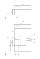
- FIG. 1 (a) and 1 (b) are views showing the coil component core according to the first embodiment, in which FIG. 1 (a) is a plan view and FIG. 1 (b) is FIG. 1 (a). It is the side view seen in the arrow B direction.
- 2 (a) and 2 (b) are views showing the core body of the coil component core according to the first embodiment, in which FIG. 2 (a) is a plan view and FIG. 2 (b) is FIG. It is the side view seen in the arrow B direction of (a).
- 3 (a) and 3 (b) are views showing a gap core of the coil component core according to the first embodiment, in which FIG. 3 (a) is a plan view and FIG. 3 (b) is FIG.
- FIG. 5 (a) and 5 (b) are views showing the coil component core according to the second embodiment, in which FIG. 5 (a) is a plan view and FIG. 5 (b) is FIG. 5 (a). It is the side view seen in the arrow B direction.
- 6 (a), 6 (b), and 6 (c) are views showing the gap core of the coil component core according to the second embodiment, in which FIG. 6 (a) is a plan view, FIG. FIG. 6B is a side view as viewed in the direction of arrow B in FIG. 6A, and FIG. 6C is a cross-sectional view taken along line CC in FIG.
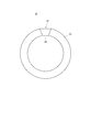
- FIG. 10 is a plan view showing a coil component core according to Modification 1.
- FIG. 10 is a plan view showing a coil component core according to Modification 2.
- FIG. 10 is a plan view showing a coil component core according to Modification 3.
- the coil component core 30 As shown in either FIG. 1 (a) or FIG. 1 (b), the coil component core 30 according to the present embodiment is arranged in an annular core body 10 having a magnetic gap 15 and the magnetic gap 15. And a gap core 20.
- the average value of the relative permeability in the entire space of the magnetic gap 15 is lower than the relative permeability of the core body 10.
- the gap core 20 has a first portion 21 having a relative permeability higher than the average value.
- the first portion 21 is disposed on at least a part of the peripheral edge of the magnetic gap 15.
- the gap core 20 preferably has a closed shape.
- the core body 10 and the gap core 20 are each made of a magnetic material.
- the entire space of the magnetic gap 15 refers to the space occupied by the gap core 20 and the air gap at the center thereof.
- the core body 10 assembles, for example, the first member 11 and the second member 12 formed in a U-shape, respectively. Therefore, it is configured in an annular shape.
- a facing surface 16 that is an end surface on one end side of the first member 11 and a facing surface 17 that is an end surface on one end side of the second member 12 are disposed to face each other.
- a facing surface 13 that is an end surface on the other end side of the first member 11 and a facing surface 14 that is an end surface on the other end side of the second member 12 are disposed to face each other.
- the facing surface 16 and the facing surface 17 are disposed in contact with or close to each other.
- the opposing surface 13 and the opposing surface 14 are spaced apart from each other.
- a facing gap between the facing surface 13 and the facing surface 14 forms a magnetic gap 15.
- the number of magnetic gaps 15 is not particularly limited, and may be one, for example, or two or more. Further, there is no restriction on the number of gap cores 20 fitted in these magnetic gaps 15.
- the core body 10 is formed in, for example, a rectangular frame shape.
- the present invention is not limited to this example, and the core body 10 may have a shape such as an annular shape, an elliptical shape, or a polygonal shape other than a rectangular shape.
- the facing surface 16 and the facing surface 17 have the same shape, for example, and face each other in parallel. Further, when viewed in the normal direction of the opposing surface 16 and the opposing surface 17, the outline of the opposing surface 16 and the outline of the opposing surface 17 coincide with each other.
- the facing surface 13 and the facing surface 14 have the same shape, for example, and face each other in parallel. Further, when viewed in the normal direction of the opposing surface 13 and the opposing surface 14, the outline of the opposing surface 13 and the outline of the opposing surface 14 coincide with each other.
- the core body 10 has, for example, a rectangular cross section. That is, the first member 11 and the second member 12 have, for example, a rectangular cross section. And the opposing surface 13, the opposing surface 14, the opposing surface 16, and the opposing surface 17 are each rectangular shapes.
- the present invention is not limited to this example, and the cross-sectional shape of the core body 10 may be, for example, a circular shape, an elliptical shape, or a polygonal shape other than a rectangular shape.
- a gap core 20 is disposed in the magnetic gap 15 of the core body 10.
- the gap core 20 may be fixed to at least one of the facing surface 13 and the facing surface 14 by adhesion or the like, or may be sandwiched between the facing surface 13 and the facing surface 14.
- the gap core 20 is configured by the first portion 21.
- the first portion 21 is disposed on at least a part of the peripheral portion of the magnetic gap 15.
- the peripheral edge of the magnetic gap 15 is a region of a facing interval between the peripheral edge of the opposing surface 13 and the peripheral edge of the opposing surface 14 when viewed in the normal direction of the opposing surface 13 and the opposing surface 14.
- the peripheral edge of the facing surface 13 is the distance from the center C1 (not shown) of the facing surface 13 to the outer periphery of the facing surface 13 when viewed in the normal direction of the facing surface 13 (3L1).
- the distance from the center C1 can be an area of 2L1 or more.
- the distance L1 is a variable that changes according to the orientation with respect to the center C1.
- the peripheral edge of the facing surface 14 is the distance from the center C2 (not shown) of the facing surface 14 to the outer periphery of the facing surface 14 when viewed in the normal direction of the facing surface 14 (not shown).
- the distance from the center C2 can be an area of 2L2 or more. Note that when the facing surface 14 is non-circular as in the present embodiment, the distance L2 is a variable that varies depending on the orientation with respect to the center C2. At least a part of the first portion 21 is disposed in a region of a facing interval between the peripheral portion of the facing surface 13 and the peripheral portion of the facing surface 14.
- the first portion 21 is preferably arranged so as to avoid the central portion of the magnetic gap 15.
- the central portion of the magnetic gap 15 is a region of a facing interval between the central portion of the facing surface 13 and the central portion of the facing surface 14 when viewed in the normal direction of the facing surface 13 and the facing surface 14. More specifically, for example, the central portion of the facing surface 13 can be a region whose distance from the center C1 of the facing surface 13 is L1 or less. Similarly, for example, the central portion of the facing surface 14 can be a region whose distance from the center C2 of the facing surface 14 is L2 or less.
- the first portion 21 is formed in an annular shape.
- a region inside the first portion 21 is a gap.
- the first portion 21 is formed in a rectangular frame shape, for example.
- the first portion 21 of the gap core 20 is disposed along the peripheral edge of the magnetic gap 15.
- the fact that the first portion 21 of the gap core 20 is arranged along the peripheral edge of the magnetic gap 15 means, for example, at least a part of the first portion 21 over the entire circumference of the first portion 21. Can be located at the peripheral edge of the magnetic gap 15.
- the first portion 21 is formed in an annular shape along the peripheral edge of the magnetic gap 15.
- the 1st part 21 is contact
- the first portion 21 is in contact with the facing surface 14 in a circular manner along the peripheral edge of the facing surface 14. That is, the first portion 21 circulates along the peripheral edge of each of the opposing surfaces 13 and 14 with respect to each of the pair of opposing surfaces 13 and 14 of the core body 10 facing each other via the magnetic gap 15. It is in contact.
- the contour line of the facing surface 13, the contour line of the facing surface 14, and the contour line of the first portion 21 match. Yes. That is, in the present embodiment, the first portion 21 is disposed flush with the outer peripheral surface of the entire space of the magnetic gap 15.
- the present invention is not limited to this example, and the first portion 21 may protrude from the outer peripheral surface of the entire space of the magnetic gap 15.
- the relative permeability of the first portion 21 is preferably lower than the relative permeability of the core body 10. However, as long as the condition that the average value of the relative permeability in the entire space of the magnetic gap 15 is lower than the relative permeability of the core body 10, the relative permeability of the first portion 21 is the relative permeability of the core body 10. It may be the same as or higher than the relative permeability of the core body 10.
- the coil component 100 includes a coil component core 30 according to the present embodiment and a coil 50 wound around the coil component core 30.
- the coil component 100 is an inductor, for example.
- the coil component core 30 includes a first section 31 and a second section 32 that extend in parallel with each other, and one end portion of the first section 31 and one end section of the second section 32. And a fourth section 34 that connects the other end of the first section 31 and the other end of the second section 32 to each other.
- Each of the third section 33 and the fourth section 34 extends in a direction orthogonal to the first section 31 and the second section 32.
- the second section 32 includes the magnetic gap 15 and the gap core 20.
- the coil component 100 includes, as the coil 50, for example, a first coil 51 wound around the first section 31 and a second coil 52 wound around the second section 32.
- Each of the first coil 51 and the second coil 52 is configured by winding a wire in a spiral shape.
- the first coil 51 and the second coil 52 are connected to each other in series, for example.
- the second coil 52 is preferably wound around, for example, the magnetic gap 15 (and thus around the gap core 20).
- the average value of the relative permeability in the entire space of the magnetic gap 15 is lower than the relative permeability of the core body 10, so that the magnetic gap 15 does not exist.
- the direct current superimposition characteristics of the coil component core 30 are improved.
- the gap core 20 disposed in the magnetic gap 15 has a first portion 21 having a relative permeability higher than the average value of the relative permeability in the entire space of the magnetic gap 15, and the first portion 21 is a magnetic gap. It is arrange
- alternating current resistance (Rs) can be reduced, the loss (power loss) of the coil component 100 can be suppressed significantly.
- the coil component core 30 is compared with the case where the gap core 20 is not disposed in the magnetic gap 15. Effective relative permeability is improved.
- the winding frequency of the coil 50 of the coil component 100 can be reduced, copper loss can be reduced. Therefore, the series resistance (DCR) of the coil component 100 can be reduced.
- the first portion 21 is formed in an annular shape along the peripheral edge of the magnetic gap 15, the leakage magnetic flux can be suppressed more reliably.
- the first portion 21 circulates along the peripheral edge of each of the opposing surfaces 13, 14 with respect to each of the pair of opposing surfaces 13, 14 of the core body 10 that are opposed to each other via the magnetic gap 15. By abutting, leakage magnetic flux can be more reliably suppressed.
- the leakage magnetic flux can be more reliably suppressed.
- the direct current superposition characteristics of the coil component core 30 can be more sufficiently improved.
- the coil component core 30 according to the present embodiment is different from the coil component core 30 according to the first embodiment described above in the points described below, and is otherwise different from the first embodiment described above.
- the coil component core 30 is configured in the same manner.
- the gap core 20 includes the second portion 22 disposed in the region surrounded by the annular first portion 21.
- the relative permeability of the second portion 22 is lower than the relative permeability of the first portion 21.
- the second portion 22 is made of a magnetic material.
- the second portion 22 is filled in a region surrounded by the first portion 21 (FIG. 6C).
- the second portion 22 is filled in the region surrounded by the first portion 21.
- the second portion 22 is filled in the region surrounded by the first portion 21 without any gap ( The second portion 22 can be filled substantially in the entire region surrounded by the second member 12).
- the gap core 20 has the second portion 22 arranged in the region surrounded by the annular first portion 21, and the relative permeability of the second portion 22 is the first. It is lower than the relative permeability of the one portion 21. With this configuration, the leakage magnetic flux can be more reliably suppressed.
- the leakage magnetic flux can be more reliably suppressed.
- the coil component core 30 may include a plurality of magnetic gaps 15. And when the core 30 for coil components is provided with the some magnetic gap 15, the gap core 20 may be arrange
- a coil component core having the same configuration as that of the core body 10 having the configuration shown in FIGS. 2A and 2B was used.
- the coil component core 30 having the configuration shown in FIGS. 1A and 1B was used.
- the coil component core 30 having the configuration shown in FIGS. 5A and 5B was used.
- the second portion 22 is inserted in a region surrounded by the first portion 21 so that there is as little gap as possible between the inner peripheral surface of the first portion 21 ( Filled).
- the dimensions (dimensions D1, D2, D3, D4, and D5) of each part shown in FIGS. 2A and 2B are the dimensions shown in FIG.
- the reference numerals of the components are omitted.
- an Fe-based dust core of ⁇ 120 was used as a material for the first member and the second member constituting the core body.
- the first part of the gap core having an outer dimension of 20 mm ⁇ 20 mm was used. That is, the outer dimension of the first portion of the gap core is the same as the outer dimension of the pair of opposed surfaces that sandwich the magnetic gap.
- the dimension of the first portion of the gap core (the dimension g shown in FIGS. 3A and 6A and the dimension w shown in FIGS. 3B and 6B). ) Are the dimensions shown in FIGS.
- the facing interval between the pair of facing surfaces sandwiching the magnetic gap was 11 mm as shown in FIGS.
- the material constituting the first part of the gap core is shown in FIGS.
- the first part of each of Examples 1 to 10 was manufactured using a core material manufactured by Micrometals.
- the type of material of the first part and the relative permeability ( ⁇ value) of each example are shown in FIGS.
- the material which comprises the 2nd part of a gap core is shown in FIG.
- FIG. 10 shows the type of material of the second part of each of Examples 6 to 10 and the relative magnetic permeability ( ⁇ value).
- the material 1 is the core material mix2 manufactured by Micrometals
- the material 2 is the core material mix1 manufactured by the company
- the material 3 is the core material mix10 manufactured by the company.
- the material 4 is a mix 14 of the core material made by the company, and the material 5 is a mix 17 of the material of the core material made by the company.
- the material 6 of the second part of Examples 6 to 8 is formed by mixing and kneading carbonyl iron powder and an epoxy resin (mass ratio of 80:20) to form a sheet shape, and then curing at 150 degrees. Made.
- a flat wire with an insulating coating having a cross section of 6 mm (width) ⁇ 0.9 mm (thickness) is used, and is wound around the coil component core with the number of turns shown in FIGS. did.
- the number of turns shown in FIGS. 8 and 10 is the sum of the number of turns of the first coil and the number of turns of the second coil.
- FIG. 8 shows the DC superposition characteristics, Rs value, and loss of the comparative example and each of Examples 1 to 5. That is, the L value and the Rs value at 30 kHz and the loss when a 20 A DC voltage is applied are shown.
- the direct current superimposition characteristic is equal to or higher than that of the comparative example, and the Rs value and loss are superior to those of the comparative example.
- FIG. 10 shows the DC superposition characteristics, Rs value, and loss of the comparative example and each of Examples 6 to 10. That is, the L value and the Rs value at 30 kHz and the loss when a 20 A DC voltage is applied are shown. As shown in FIG.
- the direct current superimposition characteristic is equal to or higher than that of the comparative example, and the Rs value and the loss are superior to those of the comparative example.
- the loss could be reduced by about 25% to 35%
- the loss could be reduced by about 35% to 50%.
- the reason why such excellent characteristics were obtained in Examples 1 to 10 is that the leakage magnetic flux can be suppressed by arranging the first portion of the gap core in the magnetic gap, and as a result, the eddy current loss in the wire is reduced. This is because it was possible to reduce the copper loss by reducing Rs and reducing the number of turns of the wire.
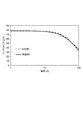
- FIG. 9 shows the relationship between applied current and inductance for Example 1.
- Example 1 as shown in FIG. 9, the DC superimposition characteristics equivalent to those of the comparative example were obtained regardless of the magnitude of the applied current.
- FIG. 11 shows the relationship between applied current and inductance for Example 6.
- Example 6 as shown in FIG. 11, the same DC superposition characteristics as in the comparative example were obtained regardless of the magnitude of the applied current.
- the toroidal core body 10 is configured by a plurality of core pieces (for example, eight core pieces p1, p2, p3, p4, p5, p6, p7, p8).
- the magnetic gap 15 may be formed between the core pieces p1 to p8, and the gap core 20 may be disposed in the magnetic gap 15.
- Each core piece (for example, eight core pieces p1 to p8) may have the same shape and dimensions, or may have different length dimensions in the magnetic path direction (circumferential direction of the toroidal shape).
- a discontinuous portion is formed at a predetermined position in the circumferential direction of the annular (C-annular) core body 10, and the discontinuous portion may be a magnetic gap 15. it can.
- a plurality of, for example, three gap cores 20 may be arranged in the magnetic gap 15 so as to be adjacent to each other in the circumferential direction of the core body 10.
- the gap cores 20 may be different from each other.
- the combination of the gap core 20 of 1st Embodiment and 2nd Embodiment and the combination of each Example are also possible.
- a trapezoidal discontinuity is formed in a predetermined position in the circumferential direction of the annular (C-annular) core body 10 in plan view, and the discontinuity is magnetized. It can also be a gap 15. Furthermore, a trapezoidal gap core 20 may be disposed in the magnetic gap 15 in plan view. The shape of the gap core 20 may be a shape other than the trapezoidal shape in plan view.
- an annular core body having a magnetic gap; A gap core disposed in the magnetic gap; With The average value of the relative permeability in the entire space of the magnetic gap is lower than the relative permeability of the core body, The gap core has a first portion having a relative permeability higher than the average value, The coil component core, wherein the first portion is disposed on at least a part of a peripheral edge of the magnetic gap.
- the coil component core according to (1), wherein the first portion is formed in an annular shape along the peripheral edge of the magnetic gap.
- the first portion is in contact with each of a pair of facing surfaces of the core body facing each other via the magnetic gap along a peripheral edge portion of each facing surface ( The core for coil parts as described in 2).
- the gap core has a second portion disposed in a region surrounded by the annular first portion, The coil component core according to (2) or (3), wherein the relative permeability of the second portion is lower than the relative permeability of the first portion.
- the first portion is disposed flush with the outer peripheral surface of the entire space of the magnetic gap, or protrudes from the outer peripheral surface of the entire space of the magnetic gap (1) to (5 The core for coil parts as described in any one of 1).
- a coil component comprising the coil component core according to any one of (1) to (7) and a coil wound around the coil component core.
Landscapes
- Engineering & Computer Science (AREA)
- Power Engineering (AREA)
- Coils Or Transformers For Communication (AREA)
Abstract
【課題】高い直流重畳特性と、漏洩磁束の抑制と、を両立させることが可能な構造のコイル部品用コアを提供する。 【解決手段】コイル部品用コア30は、磁気ギャップ15を有する環状のコア本体10と、磁気ギャップ15に配置されたギャップコア20と、を備え、磁気ギャップ15の全体空間における比透磁率の平均値が、コア本体10の比透磁率よりも低く、ギャップコア20は、上記平均値よりも比透磁率が高い第1部分21を有し、第1部分21が、磁気ギャップ15の周縁部の少なくとも一部分に配置されている。
Description
本発明は、コイル部品用コア、及び、コイル部品に関する。
特許文献1には、環状のコアと、コアに巻回されたコイルと、を備えるコイル部品が記載されている。
ところで、リアクター等のインダクタに関しては、近年はハイパワーが要求されるようになっておるため、大電流化に伴い高い直流重畳特性が重視されている。
また、高電流対応のために、コアに磁気ギャップを設けることでコイル部品の直流重畳特性を向上させる技術がある。
ところで、リアクター等のインダクタに関しては、近年はハイパワーが要求されるようになっておるため、大電流化に伴い高い直流重畳特性が重視されている。
また、高電流対応のために、コアに磁気ギャップを設けることでコイル部品の直流重畳特性を向上させる技術がある。
しかしながら、コアに磁気ギャップを設けた場合、磁気ギャップからの漏洩磁束が、コイルを構成するワイヤを貫通することにより、ワイヤ内で渦電流損失が発生する。そのため、インダクタ全体のロスが大きくなってしまう。
本発明は、上記の課題に鑑みてなされたものであり、高い直流重畳特性と、漏洩磁束の抑制と、を両立させることが可能な構造のコイル部品用コア、及び、コイル部品を提供するものである。
本発明によれば、磁気ギャップを有する環状のコア本体と、
前記磁気ギャップに配置されたギャップコアと、
を備え、
前記磁気ギャップの全体空間における比透磁率の平均値が、前記コア本体の比透磁率よりも低く、
前記ギャップコアは、前記平均値よりも比透磁率が高い第1部分を有し、
前記第1部分が、前記磁気ギャップの周縁部の少なくとも一部分に配置されているコイル部品用コアが提供される。
前記磁気ギャップに配置されたギャップコアと、
を備え、
前記磁気ギャップの全体空間における比透磁率の平均値が、前記コア本体の比透磁率よりも低く、
前記ギャップコアは、前記平均値よりも比透磁率が高い第1部分を有し、
前記第1部分が、前記磁気ギャップの周縁部の少なくとも一部分に配置されているコイル部品用コアが提供される。
また、本発明によれば、本発明のコイル部品用コアと、前記コイル部品用コアに巻回されたコイルと、を備えるコイル部品が提供される。
本発明によれば、高い直流重畳特性と、漏洩磁束の抑制と、を両立させることが可能である。
以下、本発明の実施形態について、図面を用いて説明する。なお、すべての図面において、同様の構成要素には同一の符号を付し、適宜に説明を省略する。
〔第1実施形態〕
先ず、図1(a)から図4を用いて第1実施形態を説明する。
図1(a)及び図1(b)のいずれかに示すように、本実施形態に係るコイル部品用コア30は、磁気ギャップ15を有する環状のコア本体10と、磁気ギャップ15に配置されたギャップコア20と、を備えている。
そして、磁気ギャップ15の全体空間における比透磁率の平均値が、コア本体10の比透磁率よりも低い。
ギャップコア20は、上記平均値よりも比透磁率が高い第1部分21を有する。第1部分21が、磁気ギャップ15の周縁部の少なくとも一部分に配置されている。また、ギャップコア20は閉じた形状を有することが好ましい。
コア本体10及びギャップコア20は、それぞれ磁性体により構成されている。
先ず、図1(a)から図4を用いて第1実施形態を説明する。
図1(a)及び図1(b)のいずれかに示すように、本実施形態に係るコイル部品用コア30は、磁気ギャップ15を有する環状のコア本体10と、磁気ギャップ15に配置されたギャップコア20と、を備えている。
そして、磁気ギャップ15の全体空間における比透磁率の平均値が、コア本体10の比透磁率よりも低い。
ギャップコア20は、上記平均値よりも比透磁率が高い第1部分21を有する。第1部分21が、磁気ギャップ15の周縁部の少なくとも一部分に配置されている。また、ギャップコア20は閉じた形状を有することが好ましい。
コア本体10及びギャップコア20は、それぞれ磁性体により構成されている。
ここで、磁気ギャップ15の全体空間とは、ギャップコア20及びその中心の空隙の占める空間を指す。また、磁気ギャップ15の全体空間における比透磁率の平均値とは、磁気ギャップ15の全体空間での比透磁率の平均値である。
例えば、ギャップコア20が磁気ギャップ15の全体空間の半分の領域を占めており、磁気ギャップ15に配置されているギャップコア20の比透磁率が10であるならば、磁気ギャップ15の全体空間における比透磁率の平均値は、10/2=5となる。
例えば、ギャップコア20が磁気ギャップ15の全体空間の半分の領域を占めており、磁気ギャップ15に配置されているギャップコア20の比透磁率が10であるならば、磁気ギャップ15の全体空間における比透磁率の平均値は、10/2=5となる。
図2(a)及び図2(b)のいずれかに示すように、コア本体10は、例えば、それぞれU字状の形状に形成された第1部材11及び第2部材12を相互に組み付けることにより、環状の形状に構成されている。
第1部材11の一端側の端面である対向面16と、第2部材12の一端側の端面である対向面17とが、互いに対向して配置されている。また、第1部材11の他端側の端面である対向面13と、第2部材12の他端側の端面である対向面14とが、互いに対向して配置されている。
対向面16と対向面17とは、互いに当接又は近接して配置されている。
また、対向面13と対向面14とは、互いに離間して配置されている。
対向面13と対向面14との対向間隔が磁気ギャップ15を構成している。
なお、磁気ギャップ15の数に関しては、特に制限はなく、例えば、1つでも良いし、2つ以上でも良い。また、これらの磁気ギャップ15に嵌められたギャップコア20の数に関する制限もない。
第1部材11の一端側の端面である対向面16と、第2部材12の一端側の端面である対向面17とが、互いに対向して配置されている。また、第1部材11の他端側の端面である対向面13と、第2部材12の他端側の端面である対向面14とが、互いに対向して配置されている。
対向面16と対向面17とは、互いに当接又は近接して配置されている。
また、対向面13と対向面14とは、互いに離間して配置されている。
対向面13と対向面14との対向間隔が磁気ギャップ15を構成している。
なお、磁気ギャップ15の数に関しては、特に制限はなく、例えば、1つでも良いし、2つ以上でも良い。また、これらの磁気ギャップ15に嵌められたギャップコア20の数に関する制限もない。
本実施形態の場合、コア本体10は、例えば、矩形枠状の形状に形成されている。ただし、本発明は、この例に限らず、コア本体10は、例えば、円環状、楕円環状、矩形以外の多角環状などの形状であってもよい。
対向面16と対向面17とは、例えば互いに同一形状であり、互いに平行に対向している。また、対向面16及び対向面17の法線方向に視たときに、対向面16の外形線と対向面17との外形線とが互いに一致している。
対向面13と対向面14とは、例えば互いに同一形状であり、互いに平行に対向している。また、対向面13及び対向面14の法線方向に視たときに、対向面13の外形線と対向面14との外形線とが互いに一致している。
対向面13と対向面14とは、例えば互いに同一形状であり、互いに平行に対向している。また、対向面13及び対向面14の法線方向に視たときに、対向面13の外形線と対向面14との外形線とが互いに一致している。
本実施形態の場合、コア本体10は、例えば、断面矩形状である。つまり、第1部材11及び第2部材12は、例えば、それぞれ断面矩形状である。そして、対向面13、対向面14、対向面16及び対向面17は、それぞれ矩形状となっている。
ただし、本発明は、この例に限らず、コア本体10の断面形状は、例えば、円形状、楕円形状、矩形以外の多角形状などであってもよい。
ただし、本発明は、この例に限らず、コア本体10の断面形状は、例えば、円形状、楕円形状、矩形以外の多角形状などであってもよい。
コア本体10の磁気ギャップ15にギャップコア20が配置されている。
ギャップコア20は、例えば、対向面13及び対向面14の少なくとも一方に対して接着等により固定されていても良いし、対向面13と対向面14とにより挟持されていても良い。
ギャップコア20は、例えば、対向面13及び対向面14の少なくとも一方に対して接着等により固定されていても良いし、対向面13と対向面14とにより挟持されていても良い。
本実施形態の場合、ギャップコア20は、第1部分21により構成されている。
ここで、上記のように、第1部分21は、磁気ギャップ15の周縁部の少なくとも一部分に配置されている。
磁気ギャップ15の周縁部とは、対向面13及び対向面14の法線方向に視たときの対向面13の周縁部と対向面14の周縁部との対向間隔の領域である。
ここで、上記のように、第1部分21は、磁気ギャップ15の周縁部の少なくとも一部分に配置されている。
磁気ギャップ15の周縁部とは、対向面13及び対向面14の法線方向に視たときの対向面13の周縁部と対向面14の周縁部との対向間隔の領域である。
より詳細には、例えば、対向面13の周縁部とは、対向面13の法線方向に視たときの対向面13の中心C1(不図示)から対向面13の外周までの距離を3L1(不図示)とすると、中心C1からの距離が2L1以上の領域とすることができる。なお、本実施形態のように対向面13が非円形の場合、距離L1は、中心C1を基準とした向きに応じて変化する変数である。
同様に、例えば、対向面14の周縁部とは、対向面14の法線方向に視たときの対向面14の中心C2(不図示)から対向面14の外周までの距離を3L2(不図示)とすると、中心C2からの距離が2L2以上の領域とすることができる。なお、本実施形態のように対向面14が非円形の場合、距離L2は、中心C2を基準とした向きに応じて変化する変数である。
そして、第1部分21の少なくとも一部分が、対向面13の周縁部と対向面14の周縁部との対向間隔の領域に配置されている。
同様に、例えば、対向面14の周縁部とは、対向面14の法線方向に視たときの対向面14の中心C2(不図示)から対向面14の外周までの距離を3L2(不図示)とすると、中心C2からの距離が2L2以上の領域とすることができる。なお、本実施形態のように対向面14が非円形の場合、距離L2は、中心C2を基準とした向きに応じて変化する変数である。
そして、第1部分21の少なくとも一部分が、対向面13の周縁部と対向面14の周縁部との対向間隔の領域に配置されている。
ただし、第1部分21は、磁気ギャップ15の中央部を避けて配置されていることが好ましい。
磁気ギャップ15の中央部とは、対向面13及び対向面14の法線方向に視たときの対向面13の中央部と対向面14の中央部との対向間隔の領域である。
より詳細には、例えば、対向面13の中央部とは、対向面13の中心C1からの距離がL1以下の領域とすることができる。
同様に、例えば、対向面14の中央部とは、対向面14の中心C2からの距離がL2以下の領域とすることができる。
磁気ギャップ15の中央部とは、対向面13及び対向面14の法線方向に視たときの対向面13の中央部と対向面14の中央部との対向間隔の領域である。
より詳細には、例えば、対向面13の中央部とは、対向面13の中心C1からの距離がL1以下の領域とすることができる。
同様に、例えば、対向面14の中央部とは、対向面14の中心C2からの距離がL2以下の領域とすることができる。
図3(a)及び図3(b)のいずれかに示すように、本実施形態の場合、第1部分21は、環状の形状に形成されている。そして、コイル部品用コア30において、第1部分21の内側の領域は空隙となっている。
より詳細には、第1部分21は、例えば、矩形枠状に形成されている。
そして、図1(a)及び図1(b)に示すように、ギャップコア20の第1部分21が、磁気ギャップ15の周縁部に沿って配置されている。
ここで、ギャップコア20の第1部分21が磁気ギャップ15の周縁部に沿って配置されているとは、例えば、第1部分21の環状の全周に亘り、当該第1部分21の少なくとも一部分が磁気ギャップ15の周縁部に位置すること、とすることができる。
より詳細には、第1部分21は、例えば、矩形枠状に形成されている。
そして、図1(a)及び図1(b)に示すように、ギャップコア20の第1部分21が、磁気ギャップ15の周縁部に沿って配置されている。
ここで、ギャップコア20の第1部分21が磁気ギャップ15の周縁部に沿って配置されているとは、例えば、第1部分21の環状の全周に亘り、当該第1部分21の少なくとも一部分が磁気ギャップ15の周縁部に位置すること、とすることができる。
このように、第1部分21は、磁気ギャップ15の周縁部に沿った環状に形成されている。
また、第1部分21は、例えば、対向面13に対し、当該対向面13の周縁部に沿って周回状に当接している。また、第1部分21は対向面14に対し、当該対向面14の周縁部に沿って周回状に当接している。
すなわち、第1部分21は、磁気ギャップ15を介して互いに対向しているコア本体10の一対の対向面13、14の各々に対し、各対向面13、14の周縁部に沿って周回状に当接している。
すなわち、第1部分21は、磁気ギャップ15を介して互いに対向しているコア本体10の一対の対向面13、14の各々に対し、各対向面13、14の周縁部に沿って周回状に当接している。
本実施形態の場合、対向面13及び対向面14の法線方向に視たときに、対向面13の外形線、対向面14の外形線、及び、第1部分21の外形線が一致している。
つまり、本実施形態の場合、第1部分21は、磁気ギャップ15の全体空間の外周面と面一に配置されている。
ただし、本発明は、この例に限らず、第1部分21は、磁気ギャップ15の全体空間の外周面からはみ出していても良い。
つまり、本実施形態の場合、第1部分21は、磁気ギャップ15の全体空間の外周面と面一に配置されている。
ただし、本発明は、この例に限らず、第1部分21は、磁気ギャップ15の全体空間の外周面からはみ出していても良い。
第1部分21の比透磁率は、コア本体10の比透磁率よりも低いことが好ましい。
ただし、磁気ギャップ15の全体空間における比透磁率の平均値が、コア本体10の比透磁率よりも低いという条件を満たす限りにおいて、第1部分21の比透磁率はコア本体10の比透磁率と同じであってもよいし、コア本体10の比透磁率よりも高くても良い。
ただし、磁気ギャップ15の全体空間における比透磁率の平均値が、コア本体10の比透磁率よりも低いという条件を満たす限りにおいて、第1部分21の比透磁率はコア本体10の比透磁率と同じであってもよいし、コア本体10の比透磁率よりも高くても良い。
図4に示すように、本実施形態に係るコイル部品100は、本実施形態に係るコイル部品用コア30と、コイル部品用コア30に巻回されたコイル50と、を備えて構成されている。
コイル部品100は、例えば、インダクタである。
コイル部品100は、例えば、インダクタである。
本実施形態の場合、コイル部品用コア30は、互いに平行に延在している第1区間31及び第2区間32と、第1区間31の一端部と第2区間32の一端部とを相互に連結している第3区間33と、第1区間31の他端部と第2区間32の他端部とを相互に連結している第4区間34と、を備えている。第3区間33及び第4区間34の各々は、第1区間31及び第2区間32に対して直交する方向に延在している。
なお、第2区間32は、磁気ギャップ15と、ギャップコア20と、を含んで構成されている。
なお、第2区間32は、磁気ギャップ15と、ギャップコア20と、を含んで構成されている。
そして、コイル部品100は、コイル50として、例えば、第1区間31に巻回された第1コイル51と、第2区間32に巻回された第2コイル52と、を含んでいる。
第1コイル51及び第2コイル52の各々は、ワイヤを螺旋状に巻回することにより構成されている。
第1コイル51と第2コイル52とは、例えば、相互に直列に接続されている。
なお、第2コイル52は、例えば、磁気ギャップ15の周囲(従ってギャップコア20の周囲)に巻回されていることが好ましい。
第1コイル51及び第2コイル52の各々は、ワイヤを螺旋状に巻回することにより構成されている。
第1コイル51と第2コイル52とは、例えば、相互に直列に接続されている。
なお、第2コイル52は、例えば、磁気ギャップ15の周囲(従ってギャップコア20の周囲)に巻回されていることが好ましい。
以上のような第1実施形態によれば、磁気ギャップ15の全体空間における比透磁率の平均値が、コア本体10の比透磁率よりも低いことにより、磁気ギャップ15が存在しない場合と比べて、コイル部品用コア30の直流重畳特性が向上する。
そして、磁気ギャップ15に配置されたギャップコア20は、磁気ギャップ15の全体空間における比透磁率の平均値よりも比透磁率が高い第1部分21を有し、第1部分21が、磁気ギャップ15の周縁部の少なくとも一部分に配置されている。これにより、磁束が優先的に第1部分21を通過するようにできるため、磁気ギャップ15からの漏洩磁束を抑制できる。よって、コイル50を構成するワイヤにおける渦電流損失を抑制できる。これにより、交流抵抗(Rs)を低減できるため、コイル部品100のロス(電力損失)を大幅に抑制することができる。
また、磁性体であるギャップコア20(第1部分21)が磁気ギャップ15に配置されていることにより、磁気ギャップ15にギャップコア20が配置されていない場合と比べて、コイル部品用コア30の実効比透磁率が向上する。これにより、コイル部品100のコイル50の巻回数を低減することができるため、銅損を低減することができる。よって、コイル部品100の直列抵抗(DCR)を低減することができる。
そして、磁気ギャップ15に配置されたギャップコア20は、磁気ギャップ15の全体空間における比透磁率の平均値よりも比透磁率が高い第1部分21を有し、第1部分21が、磁気ギャップ15の周縁部の少なくとも一部分に配置されている。これにより、磁束が優先的に第1部分21を通過するようにできるため、磁気ギャップ15からの漏洩磁束を抑制できる。よって、コイル50を構成するワイヤにおける渦電流損失を抑制できる。これにより、交流抵抗(Rs)を低減できるため、コイル部品100のロス(電力損失)を大幅に抑制することができる。
また、磁性体であるギャップコア20(第1部分21)が磁気ギャップ15に配置されていることにより、磁気ギャップ15にギャップコア20が配置されていない場合と比べて、コイル部品用コア30の実効比透磁率が向上する。これにより、コイル部品100のコイル50の巻回数を低減することができるため、銅損を低減することができる。よって、コイル部品100の直列抵抗(DCR)を低減することができる。
また、第1部分21が磁気ギャップ15の周縁部に沿った環状に形成されていることによって、より確実に漏洩磁束を抑制することができる。
また、第1部分21が、磁気ギャップ15を介して互いに対向しているコア本体10の一対の対向面13、14の各々に対し、各対向面13、14の周縁部に沿って周回状に当接していることによって、より確実に漏洩磁束を抑制することができる。
また、第1部分21が、磁気ギャップ15の全体空間の外周面と面一に配置されているか、又は、当該外周面からはみ出していることによって、より確実に漏洩磁束を抑制することができる。
また、第1部分21の比透磁率がコア本体10の比透磁率よりも低いことによって、コイル部品用コア30の直流重畳特性をより十分に向上させることができる。
〔第2実施形態〕
次に、図5(a)から図6(c)を用いて第2実施形態を説明する。
本実施形態に係るコイル部品用コア30は、以下に説明する点で、上記の第1実施形態に係るコイル部品用コア30と相違しており、その他の点では、上記の第1実施形態に係るコイル部品用コア30と同様に構成されている。
次に、図5(a)から図6(c)を用いて第2実施形態を説明する。
本実施形態に係るコイル部品用コア30は、以下に説明する点で、上記の第1実施形態に係るコイル部品用コア30と相違しており、その他の点では、上記の第1実施形態に係るコイル部品用コア30と同様に構成されている。
図5(a)から図6(c)のいずれかに示すように、本実施形態の場合、ギャップコア20は、環状の第1部分21に囲まれた領域に配置された第2部分22を有している。そして、第2部分22の比透磁率は、第1部分21の比透磁率よりも低い。
第2部分22は、磁性体により構成されている。
第2部分22は、磁性体により構成されている。
より詳細には、本実施形態の場合、第2部分22は、第1部分21に囲まれた領域に充填されている(図6(c))。ここで、第2部分22が第1部分21に囲まれた領域に充填されているとは、例えば、第2部分22が第1部分21に囲まれた領域に隙間無く充填されていること(第2部材12に囲まれた領域の実質的に全域に第2部分22が充填されていること)とすることができる。
以上のような第2実施形態によれば、ギャップコア20は、環状の第1部分21に囲まれた領域に配置された第2部分22を有し、第2部分22の比透磁率が第1部分21の比透磁率よりも低い。この構成によって、漏洩磁束をより確実に抑制できる。
また、第2部分22が、第1部分21に囲まれた領域に充填されていることによって、より確実に、漏洩磁束を抑制できる。
なお、上記の各実施形態では、コイル部品用コア30が備える磁気ギャップ15の数が1つである例を説明したが、コイル部品用コア30は複数の磁気ギャップ15を備えていても良い。そして、コイル部品用コア30が複数の磁気ギャップ15を備えている場合に、2つ以上の磁気ギャップ15(例えば全ての磁気ギャップ15)にそれぞれギャップコア20が配置されていても良い。
以下、各実施例および比較例を説明する。
比較例としては、図2(a)及び図2(b)に示す構成のコア本体10と同じ構成のコイル部品用コア(つまり、磁気ギャップ15の全域が空隙となっているもの)を用いた。
実施例1から実施例5としては、図1(a)及び図1(b)に示す構成のコイル部品用コア30を用いた。
実施例6から実施例10としては、図5(a)及び図5(b)に示す構成のコイル部品用コア30を用いた。なお、実施例6から実施例10においては、第1部分21に囲まれた領域に、なるべく第1部分21の内周面との間に空隙が存在しないように、第2部分22を挿入(充填)した。
比較例及び各実施例において、図2(a)及び(b)に示す各部の寸法(寸法D1、D2、D3、D4、D5)は、図7に示す寸法とした。
以下の説明では、各構成要素の符号を省略する。
実施例1から実施例5としては、図1(a)及び図1(b)に示す構成のコイル部品用コア30を用いた。
実施例6から実施例10としては、図5(a)及び図5(b)に示す構成のコイル部品用コア30を用いた。なお、実施例6から実施例10においては、第1部分21に囲まれた領域に、なるべく第1部分21の内周面との間に空隙が存在しないように、第2部分22を挿入(充填)した。
比較例及び各実施例において、図2(a)及び(b)に示す各部の寸法(寸法D1、D2、D3、D4、D5)は、図7に示す寸法とした。
以下の説明では、各構成要素の符号を省略する。
コア本体を構成する第1部材及び第2部材の材料としては、それぞれμ120のFe系ダストコアを用いた。
実施例1から実施例10では、ギャップコアの第1部分として、外形寸法が20mm×20mmのものを用いた。つまり、ギャップコアの第1部分の外形寸法は、磁気ギャップを挟む一対の対向面の外形寸法と同じとした。
実施例1から実施例10において、ギャップコアの第1部分の寸法(図3(a)及び図6(a)に示す寸法gと、図3(b)及び図6(b)に示す寸法w)は、図8及び図10に示す寸法とした。
なお、比較例において、磁気ギャップを挟む一対の対向面の対向間隔は、図8及び図10に示すように11mmとした。
実施例1から実施例10において、ギャップコアの第1部分の寸法(図3(a)及び図6(a)に示す寸法gと、図3(b)及び図6(b)に示す寸法w)は、図8及び図10に示す寸法とした。
なお、比較例において、磁気ギャップを挟む一対の対向面の対向間隔は、図8及び図10に示すように11mmとした。
ギャップコアの第1部分を構成する材料を図8及び図10に示す。
実施例1から実施例10の第1部分は、いずれもMicrometals社製のコア材を用いて作製した。各実施例の第1部分の材料の種類と、その比透磁率(μ値)を図8及び図10に示す。
また、実施例6から実施例10については、ギャップコアの第2部分を構成する材料を図10に示す。各実施例6~10の第2部分の材料の種類と、その比透磁率(μ値)を図10に示す。
図8又は図10において、材料1はMicrometals社製のコア材の材料のmix2であり、材料2は同社製のコア材の材料のmix1であり、材料3は同社製のコア材の材料のmix10であり、材料4は同社製のコア材の材料のmix14であり、材料5は同社製のコア材の材料のMix17である。
また、実施例6~8の第2部分の材料6は、カルボニル鉄粉とエポキシ樹脂(質量比で80:20)を混合及び混練してシート状の形状に成形した後に、150度で硬化させて作製した。
実施例1から実施例10の第1部分は、いずれもMicrometals社製のコア材を用いて作製した。各実施例の第1部分の材料の種類と、その比透磁率(μ値)を図8及び図10に示す。
また、実施例6から実施例10については、ギャップコアの第2部分を構成する材料を図10に示す。各実施例6~10の第2部分の材料の種類と、その比透磁率(μ値)を図10に示す。
図8又は図10において、材料1はMicrometals社製のコア材の材料のmix2であり、材料2は同社製のコア材の材料のmix1であり、材料3は同社製のコア材の材料のmix10であり、材料4は同社製のコア材の材料のmix14であり、材料5は同社製のコア材の材料のMix17である。
また、実施例6~8の第2部分の材料6は、カルボニル鉄粉とエポキシ樹脂(質量比で80:20)を混合及び混練してシート状の形状に成形した後に、150度で硬化させて作製した。
また、コイルを構成するワイヤとしては、断面が6mm(幅)×0.9mm(厚み)の絶縁被膜付きの平角ワイヤを用い、図8及び図10に示す巻回数でコイル部品用コアに巻回した。図8及び図10に示す巻回数は、上述の第1コイルの巻回数と第2コイルの巻回数との合計である。
更に、比較例と各実施例1~5の直流重畳特性と、Rs値及びロスを図8に示す。すなわち、30kHzでのL値及びRs値と、20Aの直流電圧を印加したときのロスを示す。
図8に示すように、実施例1~5のいずれにおいても、直流重畳特性については比較例と同等以上であり、Rs値とロスについて、比較例よりも優れた特性が得られた。
また、比較例と各実施例6~10の直流重畳特性と、Rs値及びロスを図10に示す。すなわち、30kHzでのL値及びRs値と、20Aの直流電圧を印加したときのロスを示す。
図10に示すように、実施例6~10のいずれにおいても、直流重畳特性については比較例と同等以上であり、Rs値とロスについて、比較例よりも優れた特性が得られた。
実施例1~5では、ロスを25%~35%程度低減でき、実施例6~10では、ロスを35%~50%程度低減できた。
実施例1~10においてこのように優れた特性が得られた理由は、磁気ギャップにギャップコアの第1部分を配置したことにより漏洩磁束を抑制でき、その結果として、ワイヤでの渦電流損失を抑制できて、Rsを低減できたとともに、ワイヤの巻回数を減少できたことにより銅損を低減できたことによる。
図8に示すように、実施例1~5のいずれにおいても、直流重畳特性については比較例と同等以上であり、Rs値とロスについて、比較例よりも優れた特性が得られた。
また、比較例と各実施例6~10の直流重畳特性と、Rs値及びロスを図10に示す。すなわち、30kHzでのL値及びRs値と、20Aの直流電圧を印加したときのロスを示す。
図10に示すように、実施例6~10のいずれにおいても、直流重畳特性については比較例と同等以上であり、Rs値とロスについて、比較例よりも優れた特性が得られた。
実施例1~5では、ロスを25%~35%程度低減でき、実施例6~10では、ロスを35%~50%程度低減できた。
実施例1~10においてこのように優れた特性が得られた理由は、磁気ギャップにギャップコアの第1部分を配置したことにより漏洩磁束を抑制でき、その結果として、ワイヤでの渦電流損失を抑制できて、Rsを低減できたとともに、ワイヤの巻回数を減少できたことにより銅損を低減できたことによる。
実施例1~5の代表例として、実施例1について、印加電流とインダクタンスとの関係を図9に示す。実施例1では、図9に示すように、印加電流の大きさにかかわらず、比較例と同等の直流重畳特性が得られた。また、図示は省略するが、他の実施例2~5についても、印加電流の大きさにかかわらず、比較例と同等の直流重畳特性が得られた。
また、実施例6~10の代表例として、実施例6について、印加電流とインダクタンスとの関係を図11に示す。実施例6でも、図11に示すように、印加電流の大きさにかかわらず、比較例と同等の直流重畳特性が得られた。また、図示は省略するが、他の実施例7~10についても、印加電流の大きさにかかわらず、比較例と同等の直流重畳特性が得られた。
このように、実施例1~10では、比較例と同等の直流重畳特性を確保しつつ、漏洩磁束を低減させて渦電流損失を低減させることができた。
特に、実施例6~10では、漏洩磁束を低減させて渦電流損失を低減させる効果に関し、実施例1~5よりも、優れた傾向が見られた。
また、実施例6~10の代表例として、実施例6について、印加電流とインダクタンスとの関係を図11に示す。実施例6でも、図11に示すように、印加電流の大きさにかかわらず、比較例と同等の直流重畳特性が得られた。また、図示は省略するが、他の実施例7~10についても、印加電流の大きさにかかわらず、比較例と同等の直流重畳特性が得られた。
このように、実施例1~10では、比較例と同等の直流重畳特性を確保しつつ、漏洩磁束を低減させて渦電流損失を低減させることができた。
特に、実施例6~10では、漏洩磁束を低減させて渦電流損失を低減させる効果に関し、実施例1~5よりも、優れた傾向が見られた。
以上、図面を参照して各実施形態を説明したが、これらは本発明の例示であり、上記以外の様々な構成を採用することもできる。また、上記の各実施形態は、本発明の主旨を逸脱しない範囲で、適宜に組み合わせることができる。
例えば、図12に示す変形例1のように、トロイダル状のコア本体10が、複数のコア片(例えば8つのコア片p1、p2、p3、p4、p5、p6、p7、p8)により構成された分割構造をなしていて、これらコア片p1~p8どうしの間に磁気ギャップ15が形成され、更にこれらの磁気ギャップ15にギャップコア20が配置されていてもよい。各コア片(例えば8つのコア片p1~p8)は、形状及び寸法が互いに等しくてもよいし、磁路方向(トロイダル形状の周方向)における長さ寸法が互いに異なっていてもよい。
また、図13に示す変形例2のように、円環状(C環状)のコア本体10の周方向における所定の位置に不連続部が形成され、その不連続部を磁気ギャップ15とすることもできる。さらに、この磁気ギャップ15には、複数、例えば3つのギャップコア20がコア本体10の周方向において互いに隣り合う配置で配置されていてもよい。また、これらのギャップコア20が互いに異なるものでも良い。例えば、第1実施形態と第2実施形態のギャップコア20の組み合わせや、各実施例の組み合わせも可能である。
また、図14に示す変形例3のように、円環状(C環状)のコア本体10の周方向における所定の位置に平面視で台形状の不連続部が形成され、その不連続部を磁気ギャップ15とすることもできる。更に、その磁気ギャップ15に、平面視で台形状のギャップコア20が配置されていてもよい。ギャップコア20の形状は、平面視台形状以外の形状であってもよい。
本実施形態は以下の技術思想を包含する。
(1)磁気ギャップを有する環状のコア本体と、
前記磁気ギャップに配置されたギャップコアと、
を備え、
前記磁気ギャップの全体空間における比透磁率の平均値が、前記コア本体の比透磁率よりも低く、
前記ギャップコアは、前記平均値よりも比透磁率が高い第1部分を有し、
前記第1部分が、前記磁気ギャップの周縁部の少なくとも一部分に配置されているコイル部品用コア。
(2)前記第1部分は、前記磁気ギャップの前記周縁部に沿った環状に形成されている(1)に記載のコイル部品用コア。
(3)前記第1部分は、前記磁気ギャップを介して互いに対向している前記コア本体の一対の対向面の各々に対し、各対向面の周縁部に沿って周回状に当接している(2)に記載のコイル部品用コア。
(4)前記ギャップコアは、環状の前記第1部分に囲まれた領域に配置された第2部分を有し、
前記第2部分の比透磁率が前記第1部分の比透磁率よりも低い(2)又は(3)に記載のコイル部品用コア。
(5)前記第2部分は、前記第1部分に囲まれた領域に充填されている(4)に記載のコイル部品用コア。
(6)前記第1部分は、前記磁気ギャップの前記全体空間の外周面と面一に配置されているか、又は、前記磁気ギャップの前記全体空間の外周面からはみ出している(1)から(5)のいずれか一項に記載のコイル部品用コア。
(7)前記第1部分の比透磁率が前記コア本体の比透磁率よりも低い(1)から(6)のいずれか一項に記載のコイル部品用コア。
(8)(1)から(7)のいずれか一項に記載のコイル部品用コアと、前記コイル部品用コアに巻回されたコイルと、を備えるコイル部品。
(1)磁気ギャップを有する環状のコア本体と、
前記磁気ギャップに配置されたギャップコアと、
を備え、
前記磁気ギャップの全体空間における比透磁率の平均値が、前記コア本体の比透磁率よりも低く、
前記ギャップコアは、前記平均値よりも比透磁率が高い第1部分を有し、
前記第1部分が、前記磁気ギャップの周縁部の少なくとも一部分に配置されているコイル部品用コア。
(2)前記第1部分は、前記磁気ギャップの前記周縁部に沿った環状に形成されている(1)に記載のコイル部品用コア。
(3)前記第1部分は、前記磁気ギャップを介して互いに対向している前記コア本体の一対の対向面の各々に対し、各対向面の周縁部に沿って周回状に当接している(2)に記載のコイル部品用コア。
(4)前記ギャップコアは、環状の前記第1部分に囲まれた領域に配置された第2部分を有し、
前記第2部分の比透磁率が前記第1部分の比透磁率よりも低い(2)又は(3)に記載のコイル部品用コア。
(5)前記第2部分は、前記第1部分に囲まれた領域に充填されている(4)に記載のコイル部品用コア。
(6)前記第1部分は、前記磁気ギャップの前記全体空間の外周面と面一に配置されているか、又は、前記磁気ギャップの前記全体空間の外周面からはみ出している(1)から(5)のいずれか一項に記載のコイル部品用コア。
(7)前記第1部分の比透磁率が前記コア本体の比透磁率よりも低い(1)から(6)のいずれか一項に記載のコイル部品用コア。
(8)(1)から(7)のいずれか一項に記載のコイル部品用コアと、前記コイル部品用コアに巻回されたコイルと、を備えるコイル部品。
Claims (8)
- 磁気ギャップを有する環状のコア本体と、
前記磁気ギャップに配置されたギャップコアと、
を備え、
前記磁気ギャップの全体空間における比透磁率の平均値が、前記コア本体の比透磁率よりも低く、
前記ギャップコアは、前記平均値よりも比透磁率が高い第1部分を有し、
前記第1部分が、前記磁気ギャップの周縁部の少なくとも一部分に配置されているコイル部品用コア。 - 前記第1部分は、前記磁気ギャップの前記周縁部に沿った環状に形成されている請求項1に記載のコイル部品用コア。
- 前記第1部分は、前記磁気ギャップを介して互いに対向している前記コア本体の一対の対向面の各々に対し、各対向面の周縁部に沿って周回状に当接している請求項2に記載のコイル部品用コア。
- 前記ギャップコアは、環状の前記第1部分に囲まれた領域に配置された第2部分を有し、
前記第2部分の比透磁率が前記第1部分の比透磁率よりも低い請求項2又は3に記載のコイル部品用コア。 - 前記第2部分は、前記第1部分に囲まれた領域に充填されている請求項4に記載のコイル部品用コア。
- 前記第1部分は、前記磁気ギャップの前記全体空間の外周面と面一に配置されているか、又は、前記磁気ギャップの前記全体空間の外周面からはみ出している請求項1から5のいずれか一項に記載のコイル部品用コア。
- 前記第1部分の比透磁率が前記コア本体の比透磁率よりも低い請求項1から6のいずれか一項に記載のコイル部品用コア。
- 請求項1から7のいずれか一項に記載のコイル部品用コアと、前記コイル部品用コアに巻回されたコイルと、を備えるコイル部品。
Applications Claiming Priority (2)
| Application Number | Priority Date | Filing Date | Title |
|---|---|---|---|
| JP2017076924A JP2018181979A (ja) | 2017-04-07 | 2017-04-07 | コイル部品用コア、及び、コイル部品 |
| JP2017-076924 | 2017-04-07 |
Publications (1)
| Publication Number | Publication Date |
|---|---|
| WO2018185989A1 true WO2018185989A1 (ja) | 2018-10-11 |
Family
ID=63713181
Family Applications (1)
| Application Number | Title | Priority Date | Filing Date |
|---|---|---|---|
| PCT/JP2018/000396 Ceased WO2018185989A1 (ja) | 2017-04-07 | 2018-01-11 | コイル部品用コア、及び、コイル部品 |
Country Status (2)
| Country | Link |
|---|---|
| JP (1) | JP2018181979A (ja) |
| WO (1) | WO2018185989A1 (ja) |
Citations (5)
| Publication number | Priority date | Publication date | Assignee | Title |
|---|---|---|---|---|
| JPH04184908A (ja) * | 1990-11-20 | 1992-07-01 | Mitsubishi Electric Corp | フライバックトランス |
| JPH05114520A (ja) * | 1991-10-22 | 1993-05-07 | Matsushita Electric Ind Co Ltd | トランス装置 |
| JP2002164232A (ja) * | 2000-11-27 | 2002-06-07 | Denso Corp | チョークコイル用コア |
| JP2011130595A (ja) * | 2009-12-18 | 2011-06-30 | Toyota Motor Corp | 燃料電池システム |
| JP2016025273A (ja) * | 2014-07-23 | 2016-02-08 | Fdk株式会社 | 巻線部品 |
Family Cites Families (4)
| Publication number | Priority date | Publication date | Assignee | Title |
|---|---|---|---|---|
| JP2003142319A (ja) * | 2001-11-05 | 2003-05-16 | Nec Tokin Corp | 圧粉磁心、コイル部品、及びそれらを用いた電力変換装置 |
| JP4304019B2 (ja) * | 2003-07-24 | 2009-07-29 | Fdk株式会社 | 磁心型積層インダクタ |
| JP2008041878A (ja) * | 2006-08-04 | 2008-02-21 | Sumitomo Electric Ind Ltd | リアクトル及びリアクトル用スペーサ |
| JP2013004931A (ja) * | 2011-06-21 | 2013-01-07 | Sumitomo Electric Ind Ltd | リアクトル、およびその製造方法 |
-
2017
- 2017-04-07 JP JP2017076924A patent/JP2018181979A/ja active Pending
-
2018
- 2018-01-11 WO PCT/JP2018/000396 patent/WO2018185989A1/ja not_active Ceased
Patent Citations (5)
| Publication number | Priority date | Publication date | Assignee | Title |
|---|---|---|---|---|
| JPH04184908A (ja) * | 1990-11-20 | 1992-07-01 | Mitsubishi Electric Corp | フライバックトランス |
| JPH05114520A (ja) * | 1991-10-22 | 1993-05-07 | Matsushita Electric Ind Co Ltd | トランス装置 |
| JP2002164232A (ja) * | 2000-11-27 | 2002-06-07 | Denso Corp | チョークコイル用コア |
| JP2011130595A (ja) * | 2009-12-18 | 2011-06-30 | Toyota Motor Corp | 燃料電池システム |
| JP2016025273A (ja) * | 2014-07-23 | 2016-02-08 | Fdk株式会社 | 巻線部品 |
Also Published As
| Publication number | Publication date |
|---|---|
| JP2018181979A (ja) | 2018-11-15 |
Similar Documents
| Publication | Publication Date | Title |
|---|---|---|
| JP6079225B2 (ja) | トランス | |
| JP7047931B2 (ja) | 巻鉄心及び変圧器 | |
| US6617950B2 (en) | Common mode/differential mode choke | |
| US10410778B2 (en) | Magnetic circuit component | |
| WO2010084677A1 (ja) | 積層インダクタ | |
| JP2010232272A (ja) | トランス | |
| JP2014123639A (ja) | インターリーブ用pfcチョークコイル | |
| JP2016207941A (ja) | コイル部品 | |
| JP2012023090A (ja) | リアクトル | |
| JP5189637B2 (ja) | コイル部品及びそれを用いた電源回路 | |
| JP6445810B2 (ja) | インターリーブ用チョークコイル | |
| JP6781043B2 (ja) | 複合磁路インダクタ | |
| JP2012023079A (ja) | リアクトル | |
| JP2002208518A (ja) | 静止誘導電磁機器 | |
| WO2018185989A1 (ja) | コイル部品用コア、及び、コイル部品 | |
| JP6956400B2 (ja) | 磁性被覆コイル及びこれを用いたトランス | |
| JP4745543B2 (ja) | 磁芯およびコイル部品 | |
| JP2011135091A (ja) | 磁芯およびコイル部品 | |
| JP6774725B2 (ja) | コイル部品 | |
| JP7773595B2 (ja) | リアクトル | |
| WO2016163084A1 (ja) | リアクトル | |
| JP2003224012A (ja) | 巻線型コイル | |
| JP2013020995A (ja) | リアクトル | |
| JP2018022783A (ja) | コイル装置 | |
| JP2025135915A (ja) | リアクトル |
Legal Events
| Date | Code | Title | Description |
|---|---|---|---|
| 121 | Ep: the epo has been informed by wipo that ep was designated in this application |
Ref document number: 18780356 Country of ref document: EP Kind code of ref document: A1 |
|
| NENP | Non-entry into the national phase |
Ref country code: DE |
|
| 122 | Ep: pct application non-entry in european phase |
Ref document number: 18780356 Country of ref document: EP Kind code of ref document: A1 |