WO2018185904A1 - 排尿予測装置及び排尿予測方法 - Google Patents
排尿予測装置及び排尿予測方法 Download PDFInfo
- Publication number
- WO2018185904A1 WO2018185904A1 PCT/JP2017/014353 JP2017014353W WO2018185904A1 WO 2018185904 A1 WO2018185904 A1 WO 2018185904A1 JP 2017014353 W JP2017014353 W JP 2017014353W WO 2018185904 A1 WO2018185904 A1 WO 2018185904A1
- Authority
- WO
- WIPO (PCT)
- Prior art keywords
- bladder
- urination
- server
- ultrasonic sensor
- ultrasonic
- Prior art date
- Legal status (The legal status is an assumption and is not a legal conclusion. Google has not performed a legal analysis and makes no representation as to the accuracy of the status listed.)
- Ceased
Links
Images





Classifications
-
- A—HUMAN NECESSITIES
- A61—MEDICAL OR VETERINARY SCIENCE; HYGIENE
- A61B—DIAGNOSIS; SURGERY; IDENTIFICATION
- A61B8/00—Diagnosis using ultrasonic, sonic or infrasonic waves
-
- A—HUMAN NECESSITIES
- A61—MEDICAL OR VETERINARY SCIENCE; HYGIENE
- A61B—DIAGNOSIS; SURGERY; IDENTIFICATION
- A61B8/00—Diagnosis using ultrasonic, sonic or infrasonic waves
- A61B8/08—Clinical applications
Definitions
- the technology disclosed herein relates to a urination prediction device and a urination prediction method.
- Patent Document 1 discloses a technique for estimating the urine volume of the bladder based on the distance between the front wall and the rear wall of the bladder.
- the technique of Patent Document 1 estimates the urine volume of the bladder at that time. Therefore, when the amount of urine is estimated, the amount of urine may already be an allowable accumulation amount or an amount close to the allowable accumulation amount. For example, in the field of nursing care, it takes time to prepare for excretion of the care recipient, so it may be too late to know that the urine volume has already reached or is close to the allowable accumulation level. is there. In addition to nursing care, it is useful to know in advance the timing of urination in various situations.
- the technology disclosed herein has been made in view of the above points, and its purpose is to predict urination timing.
- the urination prediction device disclosed herein transmits sonication into the body of a subject, and detects urination timing based on a plurality of sensors for detecting the bladder and the inflation rate of the bladder obtained from the detection results of the plurality of sensors.
- An estimation unit for estimation is provided.
- the method for predicting urination disclosed herein is obtained from a step of detecting a bladder by a plurality of sensors that transmit ultrasonic waves into the body of a subject and detect reflected waves of the ultrasonic waves, and a detection result of the bladder. And a step of estimating urination timing based on the inflation rate of the bladder.
- urination timing can be predicted.
- urination timing can be predicted.
- FIG. 1 is a schematic diagram of a urination prediction apparatus.
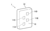
- FIG. 2 is a schematic perspective view of the transducer.
- FIG. 3 is a schematic side view of the transducer.
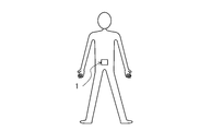
- FIG. 4 is a diagram illustrating a mounting state of the transducer.
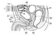
- FIG. 5 is a schematic cross-sectional view of the lower abdomen of a human body to which a transducer is attached.
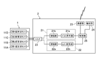
- FIG. 6 is a block diagram of the processing apparatus.
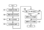
- FIG. 7 is a flowchart showing processing by the server group.
- FIG. 8 is a schematic cross-sectional view of the lower abdomen of the human body when the urine accumulation amount is medium.
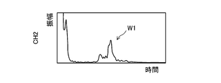
- FIG. 9 is a reception signal of the first ultrasonic sensor in the state of FIG. FIG.
- FIG. 10 is a reception signal of the second ultrasonic sensor in the state of FIG.
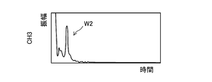
- FIG. 11 is a received signal of the third ultrasonic sensor in the state of FIG.
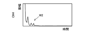
- FIG. 12 is a received signal of the fourth ultrasonic sensor in the state of FIG.
- FIG. 13 is a table showing determination results accumulated in the server group.
- FIG. 1 is a schematic diagram of a urination prediction device 100.
- the urination prediction device 100 estimates the urination timing of the subject.
- the target person is a care recipient such as an elderly person or a physically handicapped person, or a person who is not a care recipient but is incapacitated and needs time to go to the toilet.
- the target person is not limited to this.
- the urination prediction device 100 includes a transducer 1, a processing device 2 that processes a received signal of the transducer 1, and a server group 3 that analyzes a signal processed by the processing device 2.
- the transducer 1 and the processing device 2 are connected by wire.
- the processing device 2 performs wireless communication with the server group 3.
- FIG. 2 is a schematic perspective view of the transducer 1.
- FIG. 3 is a schematic side view of the transducer 1.
- the transducer 1 has four ultrasonic sensors 11A to 11D and a casing 12 that houses the ultrasonic sensors 11A to 11D.
- each of the ultrasonic sensors 11A to 11D is the same.
- the ultrasonic sensors 11A to 11D are not distinguished from each other, they are simply referred to as “ultrasonic sensor 11”.
- they are referred to as a first ultrasonic sensor 11A, a second ultrasonic sensor 11B, a third ultrasonic sensor 11C, and a fourth ultrasonic sensor 11D.
- the ultrasonic sensor 11 is an example of a sensor.
- the ultrasonic sensor 11 transmits and receives ultrasonic waves.
- the ultrasonic sensor 11 has a piezoelectric element.
- the piezoelectric element generates an ultrasonic wave by vibrating according to the driving voltage, and generates an electrical signal corresponding to the vibration when receiving the ultrasonic wave.
- the ultrasonic sensor 11 is an example of a sensor.
- the casing 12 is generally formed in a flat rectangular parallelepiped.
- the casing 12 has a relatively large area and has a pair of opposing substantially rectangular surfaces, and one surface of the casing 12 is in contact with the abdomen of the subject (hereinafter referred to as “contact surface”). 13
- the ultrasonic sensors 11A to 11D are arranged to transmit ultrasonic waves toward different positions in the direction in which the bladder expands.
- the ultrasonic sensors 11A to 11D are arranged at different positions in the vertical direction of the casing 12, as shown in FIGS.
- the first ultrasonic sensor 11A, the second ultrasonic sensor 11B, the third ultrasonic sensor 11C, and the fourth ultrasonic sensor 11D are arranged in this order from the bottom.
- the vertical direction of the casing 12 is the vertical direction when the transducer 1 is attached to the subject.
- the transducer 1 is attached to the subject in a state where the longitudinal direction of the substantially rectangular contact surface 13 coincides with the vertical direction. That is, the vertical direction of the casing 12 is the longitudinal direction of the contact surface 13.
- the left and right positions of the first ultrasonic sensor 11A and the third ultrasonic sensor 11C are the same, while the second ultrasonic sensor 11D and the fourth ultrasonic sensor 11D are the first ultrasonic sensor 11A and the third ultrasonic sensor. It is offset in the left-right direction with respect to 11C.
- the positions in the left-right direction of the second ultrasonic sensor 11C and the fourth ultrasonic sensor 11D are the same. That is, the ultrasonic sensors 11A to 11D are arranged in a staggered manner.
- the ultrasonic transmission directions of the ultrasonic sensors 11A to 11D are not parallel. As shown in FIG. 3, the ultrasonic sensors 11A to 11D transmit ultrasonic waves radially in the vertical direction. That is, the ultrasonic sensors 11A to 11D have different ultrasonic emission angles in the vertical direction. Specifically, the fourth ultrasonic sensor 11 ⁇ / b> D transmits ultrasonic waves in the normal direction of the contact surface 13. The third ultrasonic sensor 11C transmits ultrasonic waves obliquely downward from the fourth ultrasonic sensor 11A. The second ultrasonic sensor 11B transmits ultrasonic waves obliquely downward from the third ultrasonic sensor 11C.
- the first ultrasonic sensor 11A transmits an ultrasonic wave obliquely downward from the second ultrasonic sensor 11B. That is, the first ultrasonic sensor 11A transmits the ultrasonic wave most downward, and gradually transmits the ultrasonic wave upward in the order of the second ultrasonic sensor 11B, the third ultrasonic sensor 11C, and the fourth ultrasonic sensor 11D. .
- FIG. 4 is a diagram showing a mounting state of the transducer 1.
- the transducer 1 is attached to a subject as shown in FIG.
- the transducer 1 is placed on the skin of the subject's abdomen and on the part corresponding to the bladder (for example, the lower abdomen).
- the transducer 1 is attached to the abdomen with a belt or tape with the contact surface 13 in contact with the abdomen of the subject.
- a gel or the like for improving the permeability of ultrasonic waves to the abdomen is applied between the contact surface 13 and the abdomen.
- FIG. 5 is a schematic cross-sectional view of the lower abdomen of the human body to which the transducer 1 is attached.
- the example of FIG. 5 has shown the state with almost no urine storage amount.
- subcutaneous fat 61, muscle 62, fat 63, bladder 64, seminal vesicle 65 or prostate 66 (for men) or vagina (for women), rectum 67, spine (sacrum) 68, etc. are in order.
- the small intestine 69 is located on the bladder 64, and the pubic bone 610 is located obliquely below the front side of the bladder 64.
- the transducer 1 is attached to the abdomen of the subject so that the ultrasonic waves emitted from the ultrasonic sensors 11A to 11D spread in the vertical direction.
- the ultrasonic sensors 11A to 11D transmit ultrasonic waves toward different positions in the vertical direction in the body.
- the bladder swells in three dimensions as the amount of stored urine increases. Therefore, the different position in the vertical direction is one of the directions in which the bladder expands. Note that the bladder expands greatly particularly in the vertical direction. That is, the ultrasonic sensors 11A to 11D are arranged to transmit ultrasonic waves toward different positions in the direction in which the bladder expands relatively large.
- FIG. 6 is a block diagram of the processing device 2.
- the processing device 2 includes a transmission unit 21 that outputs a drive voltage to the ultrasonic sensor 11, a reception unit 22 that receives an electrical signal from the ultrasonic sensor 11, and the ultrasonic sensor 11 connected to the transmission unit 21 and the reception unit 22.
- a switch 23 for switching between, a notification unit 24 for reporting various information to the outside, a communication unit 25 for performing communication with the outside, and a control unit 26 for performing overall control of the processing device 2 Yes.
- the processing device 2 is attached to a subject's clothes and the like.
- the transmission unit 21 supplies a driving voltage to the ultrasonic sensor 11.
- the transmission unit 21 includes a pulse generator 21a and an amplification unit 21b.
- the pulse generator 21a generates a pulse signal having a predetermined pulse width and voltage value.
- the pulse generator 21a may be configured to be able to change the pulse width, the number of pulses, and the frequency.
- the amplifying unit 21b amplifies the pulse signal from the pulse generator 21a and outputs the amplified signal to the ultrasonic sensor 11 as a driving voltage.
- the receiving unit 22 receives an electrical signal from the ultrasonic sensor 11.
- the reception unit 22 includes an amplification unit 22a and an A / D conversion unit 22b.
- the amplification unit 22a amplifies the received signal from the ultrasonic sensor 11 and outputs the amplified signal to the A / D conversion unit 22b.
- the A / D converter 22b performs A / D conversion on the received signal from the amplifier 22a.
- the switch 23 selectively switches the ultrasonic sensor 11 connected to the transmission unit 21 and the reception unit 22 from the ultrasonic sensors 11A to 11D.
- the notification unit 24 is, for example, an LED lamp.
- Various information for example, arrival of urination timing is notified to the subject by the lighting mode of the LED lamp.
- the communication unit 25 communicates with an external communication device.
- the communication unit 25 performs Bluetooth (registered trademark) standard communication.
- the communication unit 25 communicates with the server group 3 via the gateway 40.
- the control unit 26 has one or a plurality of processors.
- the control unit 26 controls the transmission unit 21, the reception unit 22, the switch 23, the notification unit 24, and the communication unit 25.
- control unit 26 controls the switch 23 to switch the ultrasonic sensor 11 connected to the transmission unit 21 and the reception unit 22.
- the control unit 26 controls the transmission unit 21 to output a drive voltage to the ultrasonic sensor 11.
- the control unit 26 controls the reception unit 22 to convert the reception signal of the ultrasonic sensor 11 into a digital signal.
- the control unit 26 controls the communication unit 25 to transmit a signal from the reception unit 22 to the outside.
- the control unit 26 receives a signal from the outside via the communication unit 25, and performs processing according to the signal (for example, activates the notification unit 24).
- the server group 3 performs so-called cloud computing.
- the server group 3 includes a plurality of servers as shown in FIG. Specifically, the server group 3 includes a first server 31 that performs data analysis, a second server 32 that provides an application to the user terminal 71, and a third server 33 that receives information that affects the urination timing of the subject. And a fourth server 34 functioning as a database.
- the server group 3 is an example of an estimation unit.
- the first server 31 communicates with the processing device 2 and analyzes the signal from the processing device 2, that is, the reception signal of the ultrasonic sensor 11 received and processed by the receiving unit 22.
- the reception signal transmitted from the processing device 2 is also simply referred to as “reception signal of the ultrasonic sensor 11”.
- the first server 31 estimates urination timing based on the inflation rate of the bladder obtained from the reception signal of the ultrasonic sensor 11. At that time, the first server 31 also estimates the urine accumulation amount of the bladder from the reception signal of the ultrasonic sensor 11.
- the second server 32 communicates with the user terminal 71.
- An external communication terminal that performs communication can be registered in the server group 3 (specifically, the fourth server 34), and information on the communication terminal is stored in the server group 3 in association with the processing device 2. That is, the user registers the user terminal 71 in the server group 3 in advance. By doing so, communication between the server group 3 and the user terminal 71 becomes possible.
- a user terminal 71 for example, a smartphone or a tablet terminal
- the user terminal 71 of the target person is registered.
- the number of user terminals 71 is not limited to one, and a plurality of user terminals (for example, a user terminal 71 of a caregiver and a user terminal 71 of a care recipient) may be registered.
- the user terminal 71 can operate the dedicated application by transmitting and receiving information to and from the second server 32 by downloading an application dedicated to the urination prediction apparatus 100.
- the second server 32 receives information on the state of the subject from the user terminal 71.
- the second server 32 stores the received information in the fourth server 34.
- the information related to the state of the subject includes at least information that affects the allowable urine storage amount of the bladder (that is, the urine storage amount that causes urinary intention) and information that affects the inflation rate of the bladder.
- the information regarding the subject's condition includes information regarding food intake, information regarding beverage intake, information regarding medication, and information regarding whether or not the subject is sleeping.
- the second server 32 transmits various information such as the urination timing of the subject to the user terminal 71.
- the third server 33 receives information related to the state of the subject from an external device other than the user terminal 71.
- An example of this external device is a posture sensor.
- the posture sensor transmits information on the posture of the subject as information on the state of the subject.
- the third server 33 has a built-in posture sensor and communicates with the wearable terminal 72 worn by the subject.
- the third server 33 receives information on the posture of the target person (for example, states such as standing, sitting, and lying) from the wearable terminal 72.
- the third server 33 stores the received information in the fourth server 34.
- the fourth server 34 includes information on the target person, a reception signal of the ultrasonic sensor 11 received by the first server 31, an analysis result of the first server 31, information received by the second server 32, and a third server 33.
- the received information is stored.
- the information on the subject is, for example, a user ID that identifies the subject, a device ID that identifies the processing device 2, a terminal ID that identifies the user terminal, and information on urine storage and urination of the subject.
- the fourth server 34 stores these pieces of information in association with each other.
- the user ID, device ID, and terminal ID are registered in advance by the user.
- the information on the subject's urine storage and urination is, for example, an allowable urine storage amount (allowable urine level described later), and a common initial value is preset by default. Information relating to the urine storage and urination of the subject can be corrected by the analysis result by the first server 31.
- the transducer 1 and the processing device 2 periodically transmit and receive ultrasonic waves.
- the control unit 26 of the processing apparatus 2 causes the first to fourth ultrasonic sensors 11A to 11D to sequentially transmit and receive ultrasonic waves while switching the switch 23.
- the control unit 26 controls the switch 23 so that the first ultrasonic sensor 11A is connected to the transmission unit 21 and the reception unit 22.
- the control part 26 outputs the production
- the first ultrasonic sensor 11A transmits an ultrasonic wave based on the driving voltage and receives a reflected wave from the body.
- the reception signal of the first ultrasonic sensor 11A is amplified and A / D converted by the reception unit 22.
- the control unit 26 sequentially switches the switch 23 to execute the same control for the second to fourth ultrasonic sensors 11B to 11D.
- This step corresponds to a step of detecting the bladder by a plurality of sensors that transmit ultrasonic waves into the body of the subject and detect reflected waves of the ultrasonic waves.
- the control unit 26 transmits the reception signals of the first to fourth ultrasonic sensors 11A to 11D (specifically, signals processed by the reception unit 22) to the server group 3 via the communication unit 25.
- the control unit 26 periodically executes this processing with one set of transmission / reception of ultrasonic waves and transmission of received signals to the server group 3 by the first to fourth ultrasonic sensors 11A to 11D.
- FIG. 7 is a flowchart showing processing by the server group 3.
- the first server 31 receives the reception signals of the four ultrasonic sensors 11 that are periodically transmitted from the processing device 2 in step S1.
- step S2 the first server 31 determines whether or not the ultrasonic sensor 11 has detected the bladder based on the reception signal of the ultrasonic sensor 11.
- the first server 31 checks the presence / absence of bladder detection for all of the four ultrasonic sensors 11.
- the first server 31 determines that the ultrasonic sensor 1 detects the bladder when the received signal includes the reflected wave of the bladder.
- the first server 31 performs an average process on the reception signal of the ultrasonic sensor 11.
- the first server 31 adds a plurality of the latest reception signals stored in the fourth server 34 to the reception signal received from the processing device 2, and averages a predetermined number (for example, 10) of reception signals ( That is, find a moving average). Thereby, the noise of the received signal is reduced, and the reflected wave can be easily identified.
- the first server 31 determines whether or not the reflected signal of the bladder is included in the received signal after the averaging process.
- the received signal noise is observed immediately after transmission of the ultrasonic wave, so that a reflected wave from the rear wall of the bladder that is relatively far from the surface of the abdomen can be easily identified. Therefore, the first server 31 checks whether or not the received signal includes a reflected wave on the rear wall of the bladder. Since the reception time zone in which the reflected wave on the rear wall of the bladder is expected to return is generally known, the first server 31 determines whether or not there is a reflected wave in the reception time zone.
- the reflected wave of the bladder means the reflected wave of the rear wall of the bladder.
- the first server 31 determines the urine level.
- the urine level is an index indicating the amount of urine stored in the bladder, and the larger the urine level, the greater the amount of urine stored.
- the first server 31 obtains the urine level based on which ultrasonic sensor 11 detects the bladder.
- the bladder expands upward as the amount of stored urine increases, while the first to fourth ultrasonic sensors 11A to 11D transmit ultrasonic waves to different positions in the vertical direction as described above. Therefore, the greater the amount of urine stored, the greater the number of ultrasonic sensors 11 that detect the bladder.
- the first server 31 determines the urine level according to which ultrasonic sensor 11 detects the bladder in order from the bottom. The urine level when none of the ultrasonic sensors 11 detects the bladder is set to “0”. The urine level when only the first ultrasonic sensor 11A detects the bladder is set to “1”.
- the urine level when only the first ultrasonic sensor 11A and the second ultrasonic sensor 11B detect the bladder is “2”.
- the urine level when only the first ultrasonic sensor 11A, the second ultrasonic sensor 11B, and the third ultrasonic sensor 11C detect the bladder is “3”.
- the urine level when all the ultrasonic sensors 11 detect the bladder is “4”.
- FIG. 8 is a schematic cross-sectional view of the lower abdomen of the human body when the urine accumulation amount is medium.
- Examples of received signals of the four ultrasonic sensors 11 in the state of the bladder in FIG. 8 are shown in FIGS.
- FIG. 9 shows a reception signal of the first ultrasonic sensor 11A.
- FIG. 10 shows a reception signal of the second ultrasonic sensor 11B.
- FIG. 11 shows a reception signal of the third ultrasonic sensor 11C.
- FIG. 12 shows a reception signal of the fourth ultrasonic sensor 11D.
- the waveforms in FIGS. 9 to 12 are waveforms after the averaging process is performed.
- the first ultrasonic sensor 11A and the second ultrasonic sensor 11B detect the reflected wave W1 of the bladder
- the third ultrasonic sensor 11C and the fourth ultrasonic sensor 11D detect the reflected wave of the bladder. Not. That is, the urine level is “2”.
- the small intestine 69 is located on the bladder 64. Most of the ultrasonic waves emitted from the third ultrasonic sensor 11C and the fourth ultrasonic sensor 11D are incident on the small intestine 69. Since gas is mixed inside the small intestine 69, the ultrasonic wave is attenuated by the small intestine 69 and is difficult to reach the back of the body. Therefore, in the reception signals of the third ultrasonic sensor 11C and the fourth ultrasonic sensor 11D (see FIGS. 11 and 12), the reflected wave W2 of the small intestine is observed, but the reflection of the bladder is reflected after the reflected wave W2 of the small intestine.
- the small intestine 69 since the small intestine 69 always performs peristaltic movement, the reflected wave W2 of the small intestine does not appear as a clear peak but may have a waveform similar to noise (see FIG. 12). Further, depending on the degree of expansion of the bladder 64, the small intestine 69 and the bladder 64 may exist on the ultrasonic wave propagation path. In this case, since there are few small intestines 69 on the propagation path of an ultrasonic wave, a part of ultrasonic wave reaches the bladder 64 and the reflected wave of the bladder can be observed. At this time, a reflected wave of the small intestine and a reflected wave of the bladder can be observed.
- the first server 31 stores the determination result in the fourth server 34 in step S4.
- the determination result includes the determination time, the presence / absence of detection of the bladder of each ultrasonic sensor 11, and the urine level.
- the determination result is accumulated in the fourth server 34 in the form of a table as shown in FIG.
- the determination result at the determination time 9:00 in FIG. 13 is the result of the reception signal in FIGS. 9 to 12.
- the symbol “0” in each of the ultrasonic sensors 11 indicates that the bladder is not detected, and the symbol “1” indicates that the bladder is detected.
- the first server 31 also stores the received signal of the ultrasonic sensor 11 received from the processing device 2 in the fourth server 34.
- step S5 the first server 31 compares the current determination result with the previous determination result to determine whether or not the urine level has changed (that is, the new ultrasonic sensor 11 detects the bladder). Or not).
- the first server 31 compares the determination result of 9:00 that is the current determination result with the determination result of 8:50 that is the previous determination result. As a result of the comparison, the urine level is changed from “1” to “2”.
- the first server 31 estimates the urination timing based on the inflation rate of the bladder in step S6. This step corresponds to a process of estimating the urination timing based on the bladder inflation speed obtained from the bladder detection result.
- the first server 31 first obtains a time T (hereinafter referred to as “step-up time”) T from when the urine level changes last time to this time. Specifically, when the new ultrasonic sensor 11 detects the bladder as compared with the previous determination result, the ultrasonic sensor 11 that is one step lower than the new ultrasonic sensor 11 detects the bladder for the first time. The time until the new ultrasonic sensor 11 detects the bladder after the start of the operation is obtained as the step-up time T.
- the new ultrasonic sensor 11 is the second ultrasonic sensor 11B
- the one-step downward ultrasonic sensor 11 is the first ultrasonic sensor 11A.
- the value obtained by dividing the volume difference of the bladder corresponding to the one-stage urine level by the step-up time T is the bladder inflation rate.
- the first server 31 estimates the time (hereinafter, “remaining time”) X from the current urine level to the allowable urine level based on the inflation rate of the bladder.
- the allowable urine level is a urine level that causes the subject to urinate, and is set to level “4” in the initial state.
- the first server 31 estimates the remaining time X from the urine level “2” to “4”.
- the volume difference of the bladder corresponding to one stage of the urine level depends on the emission directions of the ultrasonic waves of the four ultrasonic sensors 11. That is, as the difference in the emission angle between the ultrasonic sensors 11 increases, the bladder volume difference corresponding to one urine level increases.
- the urine level and the bladder volume are substantially proportional (that is, the bladder volume difference corresponding to one stage of urine level is substantially equal between urine levels “0” and “4”).
- the ultrasonic emission direction of each ultrasonic sensor 11 is set. That is, if the bladder volume difference when the urine level increases from “1” to “2” is ⁇ Q, the bladder volume difference when the urine level increases from “2” to “4” is 2 ⁇ Q. Further, when the urine level increases from “1” to “2”, the inflation rate V of the bladder is ⁇ Q / T. Then, the remaining time X is as shown in Expression (1).
- the remaining time X is obtained from the level difference between the allowable urine level and the current urine level and the step-up time T.
- the remaining time X is 60 minutes.
- the first server 31 uses the corresponding bladder volume difference to The expansion speed and the remaining time X are determined.
- the bladder volume difference when the urine level increases from “1” to “2” is ⁇ Q 1 ⁇ 2
- the bladder volume difference when the urine level increases from “2” to “3” is ⁇ Q 2 ⁇ 3
- the volume difference of the bladder when the urine level increases from “3” to “4” is set to ⁇ Q 3 ⁇ 4 .
- the inflation rate V of the bladder when the urine level increases from “1” to “2” is ⁇ Q 1 ⁇ 2 / T.
- the remaining time X is expressed by Equation (2).
- the volume of the bladder may be evaluated in consideration of the size in the front-rear direction of the bladder, that is, the direction in which the ultrasound is emitted.
- the bladder is most prominently expanded in the vertical direction, but is also expanded in the front-rear direction.
- Which ultrasonic sensor 11 detects the bladder represents the degree of expansion of the bladder in the vertical direction.
- the time until the reflected wave of the bladder returns represents the degree of expansion of the bladder in the direction in which the ultrasound is emitted. Therefore, the bladder volume difference ⁇ Q n ⁇ n + 1 when the urine level increases by one step from “n” to “n + 1” may be obtained by the following equation (3).
- ⁇ Q n ⁇ n + 1 ⁇ q n ⁇ n + 1 ⁇ Tr (3)
- Tr is the detection time of the reflected wave W1 of the bladder. That is, the bladder volume difference ⁇ Q n ⁇ n + 1 varies depending on the detection time Tr of the reflected wave W1 of the bladder, that is, the time until the reflected wave W1 of the bladder returns.
- the volume difference of the bladder can be obtained with higher accuracy, and as a result, the bladder inflation speed V and the remaining time X can be obtained with higher accuracy.
- the first server 31 considers information on the state of the subject stored in the fourth server 34 when estimating the urination timing. For example, when the intake amount and intake time of the subject's food or beverage are stored in the fourth server 34, the first server 31 increases the bladder inflation speed V according to the intake amount and intake time. to correct. This is because the urine accumulation speed increases due to the moisture and beverage in the food. The first server 31 corrects the inflation rate V of the bladder in accordance with the medicine type and the medication / medication time stored in the fourth server 34. This is because some medicines have a diuretic action and others have an action to suppress urinary intention. When the information indicating that the subject is sleeping is stored in the fourth server 34, the first server 31 corrects the inflation rate V of the bladder slowly.
- the first server 31 corrects the bladder inflation speed V and the allowable urine level accordingly. This is because the shape of the bladder changes depending on the posture of the subject, so that the height of the bladder corresponding to the allowable urine level changes. For example, in the standing position, the height of the bladder is lower than that in the supine position, while the depth and lateral sizes of the bladder are increased. Therefore, the first server 31 lowers the allowable urine level (from “4” to “3”) and slows the inflation rate V of the bladder.
- the first server 31 corrects the urination timing accordingly.
- the first server 31 may directly correct the urination timing instead of correcting the bladder inflation speed V and the allowable urine level.
- the first server 31 notifies the processing device 2 and the user terminal 71 of the remaining time X as the urination timing.
- the 1st server 31 may alert
- the first server 31 stores the remaining time X and the expected time of urination in the fourth server 34.
- the processing device 2 When the processing device 2 receives the urination timing (remaining time X) from the first server 31, the processing device 2 operates the notification unit 24 according to the urination timing. For example, the processing device 2 turns on the LED lamp that is the notification unit 24 according to the urination timing. When a plurality of LED lamps are provided, the processing apparatus 2 turns on the LED lamps corresponding to the remaining time X. When there is one LED lamp, the processing device 2 changes the lighting mode according to the urination timing, such as increasing the blinking speed according to the remaining time X. Thereby, the subject can know the urination timing in advance and can prepare for urination.
- the urination timing is notified to the owner of the user terminal 71 by displaying the urination timing in a dedicated application. Thereby, it is possible to inform the holder of the user terminal 71 of the urination timing in advance and to prompt the preparation for guiding the subject person to the toilet.
- step S7 If there is no change in the urine level in step S5, the first server 31 proceeds to step S7 without estimating the urination timing.
- step S ⁇ b> 7 the first server 31 notifies the processing device 2 and the user terminal 71 of the most recently estimated urination timing (that is, the urination timing when the urine level has changed most recently before that). For example, at the next determination when the reception signals of FIGS. 9 to 12 are obtained, it is highly likely that the urine level remains “2”. In such a case, since the urine level has not changed, the first server 31 proceeds to step S7 without newly estimating the urination timing. And the 1st server 31 alert
- the first server 31 reports the time obtained by subtracting the elapsed time from the remaining time X as the urination timing. If the urination timing has not been estimated before that (for example, if the urine level continues to be “0”), the first server 31 returns to step S1 without notifying the estimated timing.
- the first server 31 estimates the urination timing by repeating the above processing, and notifies the subject or the people around it in advance of the urination timing.
- the step-up time T is sequentially acquired as the urine level sequentially increases (for example, it is necessary for the urine level to increase from “1” to “2”).
- the first server 31 estimates the urination timing using the latest step-up time T (that is, the step-up time T 2 ⁇ 3 ). By doing so, the first server 31 can estimate the urination timing based on the latest urine accumulation state.
- the first server 31 may estimate the urination timing using a plurality of step-up times T. For example, the first server 31 may obtain the average inflation rate of the bladder using a plurality of step-up times T, and obtain the urination timing based on the average inflation rate.
- the first server 31 corrects the allowable urine level based on the actual urination. Specifically, when the urination is actually finished, the user terminal 71 is operated by a third party such as a subject or a caregiver to input the actual urination time. The user terminal 71 transmits the actual urination time to the second server 32. The user terminal 71 may input the actual urination instead of the actual urination time. In that case, the input time indicating that there was actual urination may be regarded as the actual urination time.
- the second server 32 When the second server 32 receives the actual urination time from the user terminal 71, the second server 32 compares the predicted urination time stored in the fourth server 34 with the actual urination time. The second server 32 corrects the allowable urine level based on the difference between the expected urination time and the actual urination time. For example, when the actual urination time is earlier than the expected time, the second server 32 decreases the allowable urine level by one level (for example, from “4” to “3”). When the actual urination time is later than the expected time, the second server 32 increases the allowable urine level by one level. When the allowable urine level is maximum, that is, “4”, the second server 32 sets an additional time to be added to the expected time X.
- the expected time X is a time until the urine level reaches “4”. By adding an additional time to the predicted time, the allowable urine level is set to a virtual level of “4” or more.
- the second server 32 stores the corrected allowable urine level and / or additional time in the fourth server 34.
- the first server 31 uses the allowable urine level and / or the additional time stored in the fourth server 34.
- the second server 32 receives the actual urination time from the user terminal 71, the second server 32 simply stores the actual urination time in the fourth server 34, and the first server 31 allows the allowable urine when estimating the urination timing. Level correction may also be performed.
- the actual urination amount may be input as feedback of actual urination.
- the amount of urination may be managed.
- the actual amount of urination may be fed back.
- the allowable urine level may be corrected based on the actual amount of urination.
- the first server 31 may perform the following determination when determining whether or not the ultrasonic sensor 11 detects the bladder in step S2.
- the first server 31 includes a bladder reflected wave in the reception signal of the ultrasonic sensor 11 and the amplitude of the reflected wave of the small intestine is equal to or smaller than a predetermined threshold (even if the reflected wave of the small intestine is not included). If it is included), it may be determined that the bladder is detected in step S2. That is, since the internal organs are deformed and moved relatively flexibly, when the ultrasonic sensor 11 starts to detect the reflected wave of the bladder, the ultrasonic sensor 11 detects the reflected wave of the bladder, If it is not detected, the detection of the reflected wave becomes unstable. As a result, the urine level frequently changes in the determination of the urine level described above, and the determination of the urination timing becomes unstable.
- the small intestine 69 and the bladder 64 exist on the ultrasonic wave propagation path of the ultrasonic sensor 11.
- the bladder 64 expands from there, the small intestine 69 is pushed upward, and the small intestine 69 located on the propagation path decreases. That is, when the reflected wave of the small intestine becomes small or disappears, it can be determined that the ultrasonic sensor 11 has stably detected the bladder. Therefore, even if the reception signal of the ultrasonic sensor 11 includes the reflected wave of the bladder, the reflected wave of the small intestine is also included and the amplitude of the reflected wave of the small intestine is large (specifically, larger than a predetermined threshold).
- the first server 31 does not determine that the bladder is detected in step S2.
- the first server 31 determines that the bladder is detected in step S2.
- the ultrasonic sensor 11 will continue to detect the reflected wave of the bladder even if the subject moves and the shape and position of the bladder change somewhat.
- the first server 31 determines whether the reflected wave of the bladder is detected regardless of the presence of the reflected wave of the small intestine. You may determine with having detected.
- the first server 31 determines that the bladder is detected when a state in which the reflected signal of the bladder is included in the reception signal of the ultrasonic sensor 11 continues a predetermined number of times. May be. That is, as described above, when the ultrasonic sensor 11 starts to detect the reflected wave of the bladder, even if the reflected signal of the bladder is included in the received signal of the ultrasonic sensor 11, May not contain the reflected wave of the bladder.
- the state that the reflected signal of the bladder is included in the reception signal of the ultrasonic sensor 11 continues for a predetermined number of times, the amount of urine accumulated from when the ultrasonic sensor 11 starts to detect the reflected wave of the bladder. Has increased to some extent, and it is likely that the bladder is further inflated. As a result, even if the shape and position of the bladder change somewhat, the ultrasonic sensor 11 continues to detect the reflected wave of the bladder, so the determination of urination timing is stable.
- the first server 31 is configured so that when the reception signal of the ultrasonic sensor 11 includes the reflected wave of the bladder and the amplitude of the reflected wave of the small intestine is equal to or smaller than the predetermined threshold value, the first server 31 continues the bladder It may be determined that is detected.
- the urination prediction apparatus 100 transmits ultrasonic waves to the body of the subject and detects a plurality of ultrasonic sensors 11 (sensors) to detect the bladder and the bladder obtained from the detection results of the plurality of ultrasonic sensors 11. And a server group 3 (estimating unit) for estimating the urination timing based on the inflation rate.
- the urination prediction method of the urination prediction apparatus 100 includes a step of detecting a bladder by a plurality of ultrasonic sensors 11 that transmit ultrasonic waves into a subject's body and detect reflected waves of the ultrasonic waves, and a detection result of the bladder. And a step of estimating urination timing based on the required inflation rate of the bladder.
- the inflation rate of the bladder can be obtained based on the detection results of the plurality of ultrasonic sensors 11. If the inflation rate of the bladder is known, it is possible to estimate the time until the bladder expands to a volume corresponding to the urination timing. Thus, the urination prediction apparatus 100 can predict the urination timing.
- the plurality of ultrasonic sensors 11 are arranged such that the number of ultrasonic sensors 11 for detecting the bladder increases as the bladder expands, and the server group 3 is one of the plurality of ultrasonic sensors 11. Based on the time from when the ultrasonic sensor 11 detects the bladder until another ultrasonic sensor 11 of the plurality of ultrasonic sensors 11 detects the bladder, that is, based on the step-up time T. Estimate urination timing.
- each ultrasonic sensor 11 detects the bladder means that the bladder has expanded to a volume corresponding to the ultrasonic sensor 11. Therefore, the step-up time T from when one ultrasonic sensor 11 detects the bladder until another ultrasonic sensor 11 detects the bladder is the volume corresponding to the one ultrasonic sensor 11. It is the time required for the bladder to expand to a volume corresponding to another ultrasonic sensor 11.
- the relationship between the step-up time T and the volume difference corresponding thereto corresponds to the inflation rate of the bladder.
- the server group 3 can estimate the urination timing based on the inflation rate of the bladder by using the step-up time T.
- the plurality of ultrasonic sensors 11 are arranged to transmit ultrasonic waves toward different positions in the direction in which the bladder expands.
- the server group 3 corrects the urination timing based on information on the state of the subject.
- the server group 3 estimates the urination timing based on information on the state of the subject in addition to the inflation rate of the bladder. Thereby, the server group 3 can estimate the urination timing more accurately.
- the information regarding the state of the subject includes at least one of food intake, beverage intake, drug intake, whether or not sleeping, and the posture of the subject.
- the senor is not limited to the ultrasonic sensor 11. Any sensor other than the ultrasonic sensor can be used as long as it can detect the bladder.
- the number of ultrasonic sensors 11 is not limited to four.
- the number of ultrasonic sensors 11 may be 3 or less, or 5 or more.
- the arrangement of the plurality of ultrasonic sensors 11 is not limited to the above arrangement.
- the plurality of ultrasonic sensors 11 can be arranged at arbitrary positions as long as the ultrasonic waves are transmitted to different positions in the bladder expansion direction.
- the ultrasonic sensor 11 may not be offset in the left-right direction.
- the ultrasonic sensors 11 may be arranged in the left-right direction at the same position in the vertical direction, and may be arranged so that the emission angles are different from each other.
- the ultrasonic sensors 11 may be arranged at different positions in the vertical direction so that the emission directions are parallel to each other.
- the ultrasonic sensor 11 may be arranged so as to transmit ultrasonic waves to different positions in a two-dimensional direction as well as in a one-dimensional direction such as the vertical direction.
- a plurality of ultrasonic sensors 11 that transmit ultrasonic waves to different positions in the vertical direction and a plurality of ultrasonic sensors 11 that transmit ultrasonic waves to different positions in the horizontal direction may be provided.
- the casing 12 is not limited to the above configuration.
- a protrusion may be provided on the contact surface 13 of the casing 12.
- the ultrasonic sensor 11 is built in the protrusion.
- the protruding portion improves the adhesion with the skin (body surface) of the casing 12 in which the ultrasonic sensor 11 is built, and promotes the incidence of ultrasonic waves on the human body. Thereby, the detection ability of the bladder is enhanced.
- the mounting method of the transducer 1 is not limited to the above method.
- the contact surface 13 may be formed of a sticky adhesive surface, and the contact surface 13 may be attached to the abdomen of the subject.
- the transducer 1 and the processing device 2 are configured separately, but are not limited to this.
- the transducer 1 and the processing device 2 may be integrally configured.
- the transducer 1 and the processing apparatus 2 are not connected by wire, and may be wirelessly communicated.
- the transducer 1 may have a part of the function of the processing device 2 (for example, the transmission unit 21 or the reception unit 22).
- the configuration of the processing device 2 is not limited to the above-described configuration.
- the transmission unit 21 inputs a pulse signal as a drive signal to the transducer 1, but the drive signal is not limited to the pulse signal.
- the drive signal may be a burst wave or the like instead of a pulse wave.
- reporting part 24 is not restricted to an LED lamp, A display, an alarm, or a vibrator may be sufficient.
- the server group 3 it is not necessary for the server group 3 to estimate the urination timing from the received signal.
- the processing device 2 may estimate the urination timing.
- the urination prediction apparatus 100 may not include the server group 3.
- the PC or user terminal may estimate the urination timing. That is, the estimation unit may be a device other than the server group 3.
- the processing device 2 may have a part of the functions of the server group 3 (for example, determination of whether average processing or bladder is detected).
- the server group 3 has a plurality of servers, but one server may have the functions of the first to fourth servers 31 to 34.
- the information regarding the state of the target person is not limited to the above-described information, and may include information other than the above-described information, and a part of the above-described information may be omitted.
- the input of information related to the state of the subject person is not limited to the user terminal 71 and the wearable terminal 72.
- Information regarding the state of the target person may be input from a device other than the user terminal 71 and the wearable terminal 72.
- the operation of the urination prediction device described above is only an example. As long as the urination timing is estimated based on the bladder inflation speed obtained from the detection result of the ultrasonic sensor 11, the above-described operation may be appropriately changed, omitted, or added. For example, if the device (the processing device 2 and the user terminal 71) that receives the estimated urination timing has a time measuring function, the urination timing may not be notified when there is no change in the expected urination time.
- the detection of the reflected wave by the ultrasonic sensor 11 and the determination of the presence or absence of a change in the urine level are performed periodically, but are not limited thereto.
- the urination prediction apparatus 100 may detect the reflected wave by the ultrasonic sensor 11 and determine whether or not the urine level has changed when the subject is in a predetermined posture.
- the shape and position of the bladder in the body can vary depending on the posture of the subject. Therefore, by unifying the posture of the subject when transmitting and detecting ultrasonic waves, the bladder can be detected with high accuracy and the urine level can be determined with high accuracy.
- the urination prediction apparatus 100 may determine whether or not there is a change in the urine level using a reflected wave detected in a predetermined posture among the reflected waves periodically detected by the ultrasonic sensor 11. Good.
- the urination prediction device 100 may be configured to urge the subject to take a predetermined posture when detecting the reflected wave by the ultrasonic sensor 11.
- the urination prediction apparatus 100 determines the urine level depending on which ultrasonic sensor 11 detects the bladder, but is not limited to this.
- the urination prediction apparatus 100 may simply determine the urine level based on the number of the ultrasonic sensors 11 detecting the bladder. For example, the urination prediction apparatus 100 may determine that the urine level increases as the number of the ultrasonic sensors 11 detecting the bladder increases.
- the ultrasonic sensor 11 may not react in the order from the first ultrasonic sensor 11A toward the fourth ultrasonic sensor 11D. In such a case, determination based on the number of ultrasonic sensors 11 detecting the bladder is effective.
- the ultrasonic sensor 11 having a high degree of bladder expansion detects the bladder
- the ultrasonic sensor 11 having a lower degree of bladder expansion than that does not detect the bladder it may be determined that it is detected.
- the second ultrasonic sensor 11B may be regarded as detecting the bladder.
- the bladder is expanded to such an extent that the reflected wave of the bladder is originally detected, the reflected wave of the bladder may not be detected due to various causes in the body. In such a case, the bladder is detected. It may be determined that
- the technique disclosed herein is useful for a urination prediction device and a urination prediction method.
Landscapes
- Life Sciences & Earth Sciences (AREA)
- Health & Medical Sciences (AREA)
- Biomedical Technology (AREA)
- Biophysics (AREA)
- Nuclear Medicine, Radiotherapy & Molecular Imaging (AREA)
- Pathology (AREA)
- Radiology & Medical Imaging (AREA)
- Engineering & Computer Science (AREA)
- Physics & Mathematics (AREA)
- Heart & Thoracic Surgery (AREA)
- Medical Informatics (AREA)
- Molecular Biology (AREA)
- Surgery (AREA)
- Animal Behavior & Ethology (AREA)
- General Health & Medical Sciences (AREA)
- Public Health (AREA)
- Veterinary Medicine (AREA)
- Ultra Sonic Daignosis Equipment (AREA)
Abstract
Description
図1は、排尿予測装置100の概略図である。
図2は、トランスデューサ1の概略的な斜視図である。図3は、トランスデューサ1の概略的な側面図である。
図6は、処理装置2のブロック図である。処理装置2は、超音波センサ11へ駆動電圧を出力する送信部21と、超音波センサ11から電気信号を受信する受信部22と、送信部21及び受信部22に接続される超音波センサ11を切り替えるスイッチ23と、外部に種々の情報を報知するための報知部24と、外部との通信を行う通信部25と、処理装置2の全体的な制御を行う制御部26とを有している。処理装置2は、対象者の衣服等に装着される。
サーバ群3は、所謂、クラウドコンピューティングを行う。サーバ群3は、図1に示すように、複数のサーバを含んでいる。具体的には、サーバ群3は、データ解析を行う第1サーバ31、ユーザ端末71にアプリケーションを提供する第2サーバ32と、対象者の排尿タイミングに影響を与える情報を受け付ける第3サーバ33と、データベースとして機能する第4サーバ34とを含んでいる。サーバ群3は、推定部の一例である。
以下、排尿予測装置100の処理について詳しく説明する。
つまり、残り時間Xは、許容尿レベルと今回の尿レベルとのレベル差と、ステップアップ時間Tとから求められる。図13の例では、残り時間Xは、60分となる。
さらには、膀胱の前後方向、即ち、超音波の出射方向への大きさも考慮して膀胱の容積を評価してもよい。膀胱は、上下方向への膨張が最も顕著ではあるが、前後方向へも膨張する。どの超音波センサ11が膀胱を検出しているかは、膀胱の上下方向への膨張の程度を表わしている。一方、膀胱の反射波が返ってくるまでの時間(膀胱の反射波が検出される時間)は、超音波の出射方向への膀胱の膨張の程度を表わしている。そこで、尿レベルが「n」から「n+1」へ1段階上がる場合の膀胱の容積差ΔQn→n+1を以下の式(3)で求めてもよい。
ここで、Δqn→n+1は、ΔQn→n+1を算出する際の基準値であり、各超音波センサ11の超音波の出射方向に依存する値である。Δqn→n+1は、予め設定されている。Trは、膀胱の反射波W1の検出時間である。つまり、膀胱の容積差ΔQn→n+1は、膀胱の反射波W1の検出時間Tr、即ち、膀胱の反射波W1が返ってくるまでの時間に応じて変動する。
さらに、第1サーバ31は、実際の排尿に基づいて許容尿レベルを補正する。詳しくは、実際に排尿が終了すると、対象者又は介護者等の第三者にユーザ端末71を操作して、実際の排尿の時刻を入力してもらう。ユーザ端末71は、実際の排尿時刻を第2サーバ32へ送信する。尚、ユーザ端末71に入力されるのは、実際の排尿時刻ではなく、実際の排尿があった旨であってもよい。その場合には、実際の排尿があった旨の入力時刻を実際の排尿時刻とみなしてもよい。
尚、第1サーバ31は、ステップS2において超音波センサ11が膀胱を検出しているか否かを判定する際に以下のような判定を行ってもよい。
以上のように、本出願において開示する技術の例示として、前記実施形態を説明した。しかしながら、本開示における技術は、これに限定されず、適宜、変更、置き換え、付加、省略などを行った実施の形態にも適用可能である。また、上記実施形態で説明した各構成要素を組み合わせて、新たな実施の形態とすることも可能である。また、添付図面および詳細な説明に記載された構成要素の中には、課題解決のために必須な構成要素だけでなく、上記技術を例示するために、課題解決のためには必須でない構成要素も含まれ得る。そのため、それらの必須ではない構成要素が添付図面や詳細な説明に記載されていることをもって、直ちに、それらの必須ではない構成要素が必須であるとの認定をするべきではない。
11 超音波センサ(センサ)
3 サーバ群(推定部)
Claims (6)
- 対象者の体内に超音波を送信し、膀胱を検出する複数のセンサと、
前記複数のセンサの検出結果から求められる膀胱の膨張速度に基づいて排尿タイミングを推定する推定部とを備える排尿予測装置。 - 請求項1に記載の排尿予測装置において、
前記複数のセンサは、膀胱を検出するセンサの個数が膀胱の膨張に従って増加するように配置されており、
前記推定部は、前記複数のセンサのうちの一のセンサが膀胱を検出するようになってから前記複数のセンサのうちの別のセンサが膀胱を検出するようになるまでの時間に基づいて排尿タイミングを推定する排尿予測装置。 - 請求項1又は2に記載の排尿予測装置において、
前記複数のセンサは、膀胱が膨張する方向における異なる位置に向かって超音波を送信するように配置されている排尿予測装置。 - 請求項1乃至3の何れか1つに記載の排尿予測装置において、
前記推定部は、対象者の状態に関する情報に基づいて排尿タイミングを補正する排尿予測装置。 - 請求項4に記載の排尿予測装置において、
前記対象者の状態に関する情報は、食料の摂取、飲料の摂取、薬の摂取、睡眠中か否か、及び、対象者の姿勢の少なくとも1つを含む排尿予測装置。 - 対象者の体内に超音波を送信し、前記超音波の反射波を検出する複数のセンサによって膀胱を検出する工程と、
膀胱の検出結果から求められる膀胱の膨張速度に基づいて排尿タイミングを推定する工程とを含む排尿予測方法。
Priority Applications (2)
| Application Number | Priority Date | Filing Date | Title |
|---|---|---|---|
| PCT/JP2017/014353 WO2018185904A1 (ja) | 2017-04-06 | 2017-04-06 | 排尿予測装置及び排尿予測方法 |
| JP2017546248A JP6338788B1 (ja) | 2017-04-06 | 2017-04-06 | 排尿予測装置及び排尿予測方法 |
Applications Claiming Priority (1)
| Application Number | Priority Date | Filing Date | Title |
|---|---|---|---|
| PCT/JP2017/014353 WO2018185904A1 (ja) | 2017-04-06 | 2017-04-06 | 排尿予測装置及び排尿予測方法 |
Publications (1)
| Publication Number | Publication Date |
|---|---|
| WO2018185904A1 true WO2018185904A1 (ja) | 2018-10-11 |
Family
ID=62487360
Family Applications (1)
| Application Number | Title | Priority Date | Filing Date |
|---|---|---|---|
| PCT/JP2017/014353 Ceased WO2018185904A1 (ja) | 2017-04-06 | 2017-04-06 | 排尿予測装置及び排尿予測方法 |
Country Status (2)
| Country | Link |
|---|---|
| JP (1) | JP6338788B1 (ja) |
| WO (1) | WO2018185904A1 (ja) |
Cited By (3)
| Publication number | Priority date | Publication date | Assignee | Title |
|---|---|---|---|---|
| TWI753506B (zh) * | 2020-07-24 | 2022-01-21 | 戴德森醫療財團法人嘉義基督教醫院 | 預測夜間排尿時間方法 |
| WO2022239404A1 (ja) | 2021-05-11 | 2022-11-17 | 日本特殊陶業株式会社 | モニタリングデバイス |
| WO2025143266A1 (ja) * | 2023-12-28 | 2025-07-03 | DFree株式会社 | 尿量推定システム、尿量推定方法及び尿量推定プログラム |
Families Citing this family (4)
| Publication number | Priority date | Publication date | Assignee | Title |
|---|---|---|---|---|
| JP7284364B2 (ja) * | 2018-06-07 | 2023-05-31 | トリプル・ダブリュー・ジャパン株式会社 | 超音波測定装置、接触判定サーバ装置、接触判定プログラム及び接触判定方法 |
| JP7259343B2 (ja) | 2019-01-18 | 2023-04-18 | トヨタ自動車株式会社 | 配車サービスシステム、配車サービス方法、およびプログラム |
| JP7462149B2 (ja) * | 2020-03-12 | 2024-04-05 | パナソニックIpマネジメント株式会社 | 部品搭載装置および部品供給装置 |
| JP2022172606A (ja) * | 2021-05-06 | 2022-11-17 | 花王株式会社 | 情報処理システム |
Citations (4)
| Publication number | Priority date | Publication date | Assignee | Title |
|---|---|---|---|---|
| JP2003190168A (ja) * | 2001-12-28 | 2003-07-08 | Jun Koyama | 尿失禁予防システム並びにセンサーパッド設計装置及び尿失禁予防機器 |
| JP2010501236A (ja) * | 2006-08-22 | 2010-01-21 | キンバリー クラーク ワールドワイド インコーポレイテッド | 失禁状態を予想する方法 |
| JP2013523305A (ja) * | 2010-04-08 | 2013-06-17 | コーニンクレッカ フィリップス エレクトロニクス エヌ ヴィ | 排尿予測 |
| JP2016043273A (ja) * | 2014-08-26 | 2016-04-04 | 大塚メディカルデバイス株式会社 | 超音波尿量測定器及び超音波尿量測定器における超音波プローブの位置決め方法 |
Family Cites Families (4)
| Publication number | Priority date | Publication date | Assignee | Title |
|---|---|---|---|---|
| US6213949B1 (en) * | 1999-05-10 | 2001-04-10 | Srs Medical Systems, Inc. | System for estimating bladder volume |
| IL158379A0 (en) * | 2003-10-13 | 2004-05-12 | Volurine Israel Ltd | Non invasive bladder distension monitoring apparatus to prevent enuresis, and method of operation therefor |
| JP4677615B2 (ja) * | 2004-03-31 | 2011-04-27 | 独立行政法人産業技術総合研究所 | 超音波尿量センサ |
| JP2011183142A (ja) * | 2010-02-09 | 2011-09-22 | Nagasaki Univ | 非侵襲尿量推定センサユニット、非侵襲尿量推定装置及び排尿管理システム |
-
2017
- 2017-04-06 WO PCT/JP2017/014353 patent/WO2018185904A1/ja not_active Ceased
- 2017-04-06 JP JP2017546248A patent/JP6338788B1/ja active Active
Patent Citations (4)
| Publication number | Priority date | Publication date | Assignee | Title |
|---|---|---|---|---|
| JP2003190168A (ja) * | 2001-12-28 | 2003-07-08 | Jun Koyama | 尿失禁予防システム並びにセンサーパッド設計装置及び尿失禁予防機器 |
| JP2010501236A (ja) * | 2006-08-22 | 2010-01-21 | キンバリー クラーク ワールドワイド インコーポレイテッド | 失禁状態を予想する方法 |
| JP2013523305A (ja) * | 2010-04-08 | 2013-06-17 | コーニンクレッカ フィリップス エレクトロニクス エヌ ヴィ | 排尿予測 |
| JP2016043273A (ja) * | 2014-08-26 | 2016-04-04 | 大塚メディカルデバイス株式会社 | 超音波尿量測定器及び超音波尿量測定器における超音波プローブの位置決め方法 |
Cited By (3)
| Publication number | Priority date | Publication date | Assignee | Title |
|---|---|---|---|---|
| TWI753506B (zh) * | 2020-07-24 | 2022-01-21 | 戴德森醫療財團法人嘉義基督教醫院 | 預測夜間排尿時間方法 |
| WO2022239404A1 (ja) | 2021-05-11 | 2022-11-17 | 日本特殊陶業株式会社 | モニタリングデバイス |
| WO2025143266A1 (ja) * | 2023-12-28 | 2025-07-03 | DFree株式会社 | 尿量推定システム、尿量推定方法及び尿量推定プログラム |
Also Published As
| Publication number | Publication date |
|---|---|
| JPWO2018185904A1 (ja) | 2019-04-11 |
| JP6338788B1 (ja) | 2018-06-06 |
Similar Documents
| Publication | Publication Date | Title |
|---|---|---|
| JP6338788B1 (ja) | 排尿予測装置及び排尿予測方法 | |
| JP6453459B2 (ja) | 尿量推定装置及び尿量推定方法 | |
| JP6012909B2 (ja) | 排便予測装置及び排便予測方法 | |
| JP6431600B2 (ja) | 便量推定装置及び便量推定方法 | |
| JP6727203B2 (ja) | 人間または動物の身体の変化をシグナリングする装着可能な超音波装置 | |
| US20170360353A1 (en) | Device and method for monitoring bladder volume of a subject | |
| CN103815888B (zh) | 生物信号测量装置以及生物信号测量方法 | |
| CN102834075A (zh) | 预测排尿 | |
| WO2005099582A1 (ja) | 超音波尿量センサ | |
| WO2021206094A1 (ja) | 排尿予測システム、排尿予測方法及び排尿予測プログラム | |
| JP7284364B2 (ja) | 超音波測定装置、接触判定サーバ装置、接触判定プログラム及び接触判定方法 | |
| EP4338681A1 (en) | Monitoring device | |
| JP2020092812A (ja) | 尿量推定用探触子、及びそれを用いた尿量推定装置 | |
| WO2020003874A1 (ja) | 尿量推定用探触子、及びそれを用いた尿量推定装置 | |
| TW201742601A (zh) | 便量推定裝置及便量推定方法 | |
| HK1235649A1 (en) | Bowel movement prediction device and bowel movement prediction method | |
| JP2025105039A (ja) | 尿量推定システム、尿量推定方法及び尿量推定プログラム |
Legal Events
| Date | Code | Title | Description |
|---|---|---|---|
| ENP | Entry into the national phase |
Ref document number: 2017546248 Country of ref document: JP Kind code of ref document: A |
|
| 121 | Ep: the epo has been informed by wipo that ep was designated in this application |
Ref document number: 17904942 Country of ref document: EP Kind code of ref document: A1 |
|
| NENP | Non-entry into the national phase |
Ref country code: DE |
|
| 32PN | Ep: public notification in the ep bulletin as address of the adressee cannot be established |
Free format text: NOTING OF LOSS OF RIGHTS PURSUANT TO RULE 112(1) EPC (EPO FORM 1205A DATED 23/01/2020) |
|
| 122 | Ep: pct application non-entry in european phase |
Ref document number: 17904942 Country of ref document: EP Kind code of ref document: A1 |