WO2018181971A1 - 管理システム、及び、運動用システム - Google Patents
管理システム、及び、運動用システム Download PDFInfo
- Publication number
- WO2018181971A1 WO2018181971A1 PCT/JP2018/013802 JP2018013802W WO2018181971A1 WO 2018181971 A1 WO2018181971 A1 WO 2018181971A1 JP 2018013802 W JP2018013802 W JP 2018013802W WO 2018181971 A1 WO2018181971 A1 WO 2018181971A1
- Authority
- WO
- WIPO (PCT)
- Prior art keywords
- pattern
- load
- exercise
- rehabilitation
- management system
- Prior art date
- Legal status (The legal status is an assumption and is not a legal conclusion. Google has not performed a legal analysis and makes no representation as to the accuracy of the status listed.)
- Ceased
Links
Images














Classifications
-
- G—PHYSICS
- G16—INFORMATION AND COMMUNICATION TECHNOLOGY [ICT] SPECIALLY ADAPTED FOR SPECIFIC APPLICATION FIELDS
- G16H—HEALTHCARE INFORMATICS, i.e. INFORMATION AND COMMUNICATION TECHNOLOGY [ICT] SPECIALLY ADAPTED FOR THE HANDLING OR PROCESSING OF MEDICAL OR HEALTHCARE DATA
- G16H20/00—ICT specially adapted for therapies or health-improving plans, e.g. for handling prescriptions, for steering therapy or for monitoring patient compliance
- G16H20/30—ICT specially adapted for therapies or health-improving plans, e.g. for handling prescriptions, for steering therapy or for monitoring patient compliance relating to physical therapies or activities, e.g. physiotherapy, acupressure or exercising
-
- A—HUMAN NECESSITIES
- A61—MEDICAL OR VETERINARY SCIENCE; HYGIENE
- A61B—DIAGNOSIS; SURGERY; IDENTIFICATION
- A61B5/00—Measuring for diagnostic purposes; Identification of persons
- A61B5/0002—Remote monitoring of patients using telemetry, e.g. transmission of vital signals via a communication network
- A61B5/0004—Remote monitoring of patients using telemetry, e.g. transmission of vital signals via a communication network characterised by the type of physiological signal transmitted
- A61B5/0006—ECG or EEG signals
-
- A—HUMAN NECESSITIES
- A61—MEDICAL OR VETERINARY SCIENCE; HYGIENE
- A61B—DIAGNOSIS; SURGERY; IDENTIFICATION
- A61B5/00—Measuring for diagnostic purposes; Identification of persons
- A61B5/24—Detecting, measuring or recording bioelectric or biomagnetic signals of the body or parts thereof
- A61B5/316—Modalities, i.e. specific diagnostic methods
- A61B5/318—Heart-related electrical modalities, e.g. electrocardiography [ECG]
- A61B5/346—Analysis of electrocardiograms
- A61B5/349—Detecting specific parameters of the electrocardiograph cycle
- A61B5/35—Detecting specific parameters of the electrocardiograph cycle by template matching
-
- A—HUMAN NECESSITIES
- A61—MEDICAL OR VETERINARY SCIENCE; HYGIENE
- A61B—DIAGNOSIS; SURGERY; IDENTIFICATION
- A61B5/00—Measuring for diagnostic purposes; Identification of persons
- A61B5/68—Arrangements of detecting, measuring or recording means, e.g. sensors, in relation to patient
- A61B5/6887—Arrangements of detecting, measuring or recording means, e.g. sensors, in relation to patient mounted on external non-worn devices, e.g. non-medical devices
- A61B5/6895—Sport equipment
-
- A—HUMAN NECESSITIES
- A61—MEDICAL OR VETERINARY SCIENCE; HYGIENE
- A61H—PHYSICAL THERAPY APPARATUS, e.g. DEVICES FOR LOCATING OR STIMULATING REFLEX POINTS IN THE BODY; ARTIFICIAL RESPIRATION; MASSAGE; BATHING DEVICES FOR SPECIAL THERAPEUTIC OR HYGIENIC PURPOSES OR SPECIFIC PARTS OF THE BODY
- A61H1/00—Apparatus for passive exercising; Vibrating apparatus; Chiropractic devices, e.g. body impacting devices, external devices for briefly extending or aligning unbroken bones
-
- A—HUMAN NECESSITIES
- A61—MEDICAL OR VETERINARY SCIENCE; HYGIENE
- A61B—DIAGNOSIS; SURGERY; IDENTIFICATION
- A61B2505/00—Evaluating, monitoring or diagnosing in the context of a particular type of medical care
- A61B2505/09—Rehabilitation or training
-
- A—HUMAN NECESSITIES
- A61—MEDICAL OR VETERINARY SCIENCE; HYGIENE
- A61B—DIAGNOSIS; SURGERY; IDENTIFICATION
- A61B5/00—Measuring for diagnostic purposes; Identification of persons
- A61B5/08—Measuring devices for evaluating the respiratory organs
- A61B5/083—Measuring rate of metabolism by using breath test, e.g. measuring rate of oxygen consumption
- A61B5/0836—Measuring rate of CO2 production
-
- A—HUMAN NECESSITIES
- A61—MEDICAL OR VETERINARY SCIENCE; HYGIENE
- A61B—DIAGNOSIS; SURGERY; IDENTIFICATION
- A61B5/00—Measuring for diagnostic purposes; Identification of persons
- A61B5/22—Ergometry; Measuring muscular strength or the force of a muscular blow
- A61B5/221—Ergometry, e.g. by using bicycle type apparatus
- A61B5/222—Ergometry, e.g. by using bicycle type apparatus combined with detection or measurement of physiological parameters, e.g. heart rate
-
- A—HUMAN NECESSITIES
- A61—MEDICAL OR VETERINARY SCIENCE; HYGIENE
- A61B—DIAGNOSIS; SURGERY; IDENTIFICATION
- A61B5/00—Measuring for diagnostic purposes; Identification of persons
- A61B5/24—Detecting, measuring or recording bioelectric or biomagnetic signals of the body or parts thereof
- A61B5/316—Modalities, i.e. specific diagnostic methods
- A61B5/318—Heart-related electrical modalities, e.g. electrocardiography [ECG]
- A61B5/346—Analysis of electrocardiograms
- A61B5/349—Detecting specific parameters of the electrocardiograph cycle
- A61B5/361—Detecting fibrillation
-
- A—HUMAN NECESSITIES
- A61—MEDICAL OR VETERINARY SCIENCE; HYGIENE
- A61B—DIAGNOSIS; SURGERY; IDENTIFICATION
- A61B5/00—Measuring for diagnostic purposes; Identification of persons
- A61B5/24—Detecting, measuring or recording bioelectric or biomagnetic signals of the body or parts thereof
- A61B5/316—Modalities, i.e. specific diagnostic methods
- A61B5/318—Heart-related electrical modalities, e.g. electrocardiography [ECG]
- A61B5/346—Analysis of electrocardiograms
- A61B5/349—Detecting specific parameters of the electrocardiograph cycle
- A61B5/363—Detecting tachycardia or bradycardia
-
- A—HUMAN NECESSITIES
- A61—MEDICAL OR VETERINARY SCIENCE; HYGIENE
- A61B—DIAGNOSIS; SURGERY; IDENTIFICATION
- A61B5/00—Measuring for diagnostic purposes; Identification of persons
- A61B5/24—Detecting, measuring or recording bioelectric or biomagnetic signals of the body or parts thereof
- A61B5/316—Modalities, i.e. specific diagnostic methods
- A61B5/318—Heart-related electrical modalities, e.g. electrocardiography [ECG]
- A61B5/346—Analysis of electrocardiograms
- A61B5/349—Detecting specific parameters of the electrocardiograph cycle
- A61B5/364—Detecting abnormal ECG interval, e.g. extrasystoles, ectopic heartbeats
-
- A—HUMAN NECESSITIES
- A61—MEDICAL OR VETERINARY SCIENCE; HYGIENE
- A61B—DIAGNOSIS; SURGERY; IDENTIFICATION
- A61B5/00—Measuring for diagnostic purposes; Identification of persons
- A61B5/24—Detecting, measuring or recording bioelectric or biomagnetic signals of the body or parts thereof
- A61B5/316—Modalities, i.e. specific diagnostic methods
- A61B5/318—Heart-related electrical modalities, e.g. electrocardiography [ECG]
- A61B5/346—Analysis of electrocardiograms
- A61B5/349—Detecting specific parameters of the electrocardiograph cycle
- A61B5/366—Detecting abnormal QRS complex, e.g. widening
-
- A—HUMAN NECESSITIES
- A61—MEDICAL OR VETERINARY SCIENCE; HYGIENE
- A61B—DIAGNOSIS; SURGERY; IDENTIFICATION
- A61B5/00—Measuring for diagnostic purposes; Identification of persons
- A61B5/48—Other medical applications
- A61B5/4866—Evaluating metabolism
-
- A—HUMAN NECESSITIES
- A61—MEDICAL OR VETERINARY SCIENCE; HYGIENE
- A61B—DIAGNOSIS; SURGERY; IDENTIFICATION
- A61B5/00—Measuring for diagnostic purposes; Identification of persons
- A61B5/74—Details of notification to user or communication with user or patient; User input means
- A61B5/746—Alarms related to a physiological condition, e.g. details of setting alarm thresholds or avoiding false alarms
-
- A—HUMAN NECESSITIES
- A61—MEDICAL OR VETERINARY SCIENCE; HYGIENE
- A61B—DIAGNOSIS; SURGERY; IDENTIFICATION
- A61B5/00—Measuring for diagnostic purposes; Identification of persons
- A61B5/74—Details of notification to user or communication with user or patient; User input means
- A61B5/7465—Arrangements for interactive communication between patient and care services, e.g. by using a telephone network
Definitions
- the present invention relates to a system for effectively managing exercise of a subject, and more particularly to a system for cardiac rehabilitation.
- Japan's aging rate (ratio of the population over 65 years old in the total population) is 26.7%, compared with the aging rate in developed countries. The rate has been the highest since 2005. In the future, the aging rate will rise as the total population decreases, and it is predicted that the aging rate will reach 39.9% in 2060 (for example, Non-Patent Document 1). Japan is facing an aging society. And along with such an aging, medical costs are increasing, and reduction of medical costs is an urgent issue for the nation. This aging trend is also seen worldwide.
- Controlling the readmission rate of discharged patients through appropriate rehabilitation can be a measure to reduce medical costs. For example, the number of patients with heart failure in Japan is estimated to be over 1.2 million, and is still on the rise, with a readmission rate within one year of 37.8%. In order to reduce this readmission rate, it is effective to continue rehabilitation, and it has been reported that the readmission rate after one year in heart failure is 30% lower in the rehabilitation group than in the non-rehabilitation group. Yes (Non-Patent Document 2).
- Patent Document 1 discloses a remote rehabilitation after discharge.
- an object of the present invention is to provide a management system and an exercise system that achieves both improved safety and an effective load.
- the present inventors have recognized that the electrocardiogram waveform data during exercise of the target is pattern-recognized and automatically controls the load device when a predetermined pattern is recognized. Invented and completed the present invention. In this way, by automatically controlling the load device by pattern recognition of the electrocardiogram waveform data, it is possible to immediately determine whether to stop or continue exercise based on the state of the target that could not be detected from the pulse or heart rate. As a result, improved safety and efficient load were achieved. Particularly when the subject is suffering from or suffering from a heart disease and the exercise is cardiac rehabilitation, the increased safety and efficient burden achieved by the present invention may be advantageous. .
- the present inventors further intended to perform rehabilitation in which the load device is automatically controlled by pattern recognition of the above electrocardiogram waveform data while the patient and the rehabilitation manager exist in different places.
- the load device is automatically controlled by pattern recognition of the above electrocardiogram waveform data while the patient and the rehabilitation manager exist in different places.
- it is necessary to pay particular attention to safety in order to remotely perform heart disease rehabilitation that can cause serious symptoms.
- the rehabilitation administrator will not be able to apply the same load to the patient as the rehabilitation performed next to the patient.
- effective rehabilitation cannot be performed.
- remote rehabilitation has a trade-off between safety and load.
- the rehabilitation system of the present invention that automatically controls the load device by pattern recognition of the electrocardiogram waveform data can solve this trade-off by realizing both an improvement in safety and an appropriate load.
- the present invention also provides the following items.
- a management system for managing exercise equipment used by a subject The exercise device includes a measurement device that measures an electrocardiogram of the subject, and a load device configured to provide a load to the subject, The management system A pattern recognition unit for recognizing a pattern of the electrocardiogram waveform data based on the electrocardiogram waveform data indicating the waveform of the electrocardiogram of the object measured by the measuring device; A control unit for controlling the load of the load device, A management system configured such that the control unit controls the load according to a pattern recognized by the pattern recognition unit.
- Item 3 The management system according to Item 1 or 2, wherein the pattern recognition unit is configured to be able to recognize a first pattern at rest before exercise of a load exercise and a second pattern during exercise.
- the pattern recognition unit recognizes a normal pattern (sinus rhythm) as the first pattern, and pattern 1 (ventricular extrasystole) and pattern 2 (frequent supraventricular extrasystole) as the second pattern ), Pattern 3 (degree II atrioventricular block (Mobitz type II)), pattern 4 (degree III atrioventricular block), pattern 5 (ventricular tachycardia), pattern 6 (ventricular fibrillation), pattern 7 (atrial fibrillation) , Pattern 8 (sinus tachycardia), pattern 9 (sinus bradycardia), pattern 10 (ST change), or pattern 11 (R on T ventricular extrasystole) were recognized In this case, the control unit controls the load device to reduce or stop the load of the load device.
- An exercise system including an exercise device used by a subject and a management system for managing the device,
- the equipment for exercise is: A measuring device for measuring the electrocardiogram of the object; A load device configured to provide a load to the subject, The management system A pattern recognition unit for recognizing a pattern of the electrocardiogram waveform data based on the electrocardiogram waveform data indicating the waveform of the electrocardiogram of the object measured by the measuring device; A control unit for controlling the load of the load device, The exercise system configured to control the load of the load device according to the pattern recognized by the pattern recognition unit.
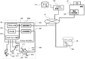
- FIG. 1 is a diagram showing an overview of a rehabilitation system 1000 according to a specific embodiment of the present invention.
- FIG. 2 is a diagram showing a specific configuration of the system management server 100 included in the rehabilitation system shown in FIG.
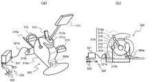
- FIG. 3 is a diagram showing a specific configuration of the information terminal device 200 included in the rehabilitation system shown in FIG. 4 is a diagram for explaining the user equipment 300 included in the rehabilitation system shown in FIG. 1, FIG. 4 (a) shows the appearance of the user side equipment, and FIG. 4 (b) shows the user equipment.
- the internal structure of is schematically shown.
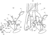
- FIG. 5 is a diagram showing a computer system 300a installed in the user equipment 300 shown in FIG. 6 is a diagram for explaining a method of using the user device 300 shown in FIG. 4.
- FIG. 5 is a diagram showing a computer system 300
- FIG. 6A shows a method of attaching the monitor device 311 and the communication terminal 312 to the user device
- FIG. b) shows the usage state of the user equipment.
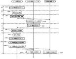
- FIG. 7 is a flowchart showing the operation of the rehabilitation system according to a specific embodiment of the present invention.
- FIG. 8 shows operations (steps S1 to S4) from the activation of the user device 300 to the rehabilitation exercise start instruction in the rehabilitation system shown in FIG. 7 in the user device, system management server, and information terminal device in the rehabilitation system. It is a figure which shows a mode that it performs by this cooperation operation
- FIG. 9 shows the operation (steps S5 to S10) from the rehabilitation exercise start instruction to its interruption in the rehabilitation system shown in FIG.
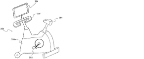
- FIG. 10 is a perspective view for explaining a configuration example of a user device having a structure in which a chair unit is integrally combined with the user device shown in FIG. 4.
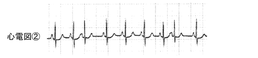
- FIG. 11A shows a typical electrocardiogram waveform pattern of a normal pattern (sinus rhythm).
- FIG. 11B shows a typical electrocardiogram waveform pattern of pattern 1 (ventricular extrasystole).
- FIG. 11C shows a typical electrocardiogram waveform pattern of pattern 2 (supraventricular extrasystole).
- FIG. 11A shows a typical electrocardiogram waveform pattern of a normal pattern (sinus rhythm).
- FIG. 11B shows a typical electrocardiogram waveform pattern of pattern 1 (ventricular extrasystole).
- FIG. 11C shows a typical electrocardiogram waveform pattern of pattern 2 (supraventricular extrasystole).
- FIG. 11A shows a typical electrocardiogram waveform pattern of a normal pattern (sinus rhythm).
- FIG. 11B shows a typical electrocardiogram
- FIG. 11D shows a typical electrocardiogram waveform pattern of pattern 3 (II degree atrioventricular block (Mobitz type II)).
- FIG. 11E shows a typical electrocardiogram waveform pattern of Pattern 4 (III degree atrioventricular block).
- FIG. 11F shows a typical electrocardiogram waveform pattern of pattern 5 (ventricular tachycardia).
- FIG. 11G shows a typical electrocardiogram waveform pattern of pattern 6 (ventricular fibrillation).
- FIG. 11H shows a typical electrocardiogram waveform pattern of pattern 7 (atrial fibrillation).
- FIG. 11I shows a typical electrocardiogram waveform pattern of pattern of pattern 8 (sinus tachycardia).
- FIG. 11J shows a typical electrocardiogram waveform pattern of pattern 9 (sinus bradycardia).
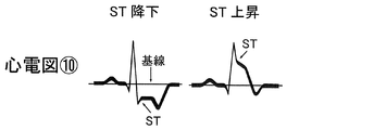
- FIG. 11K shows a typical electrocardiogram waveform pattern of pattern 10 (ST variation).
- FIG. 11L shows a typical electrocardiogram waveform pattern of pattern 11 (R on T ventricular extra
- rehabilitation refers to any approach for improving physical and mental function resulting from a disease or injury by loading a patient with a loading device.
- cardiac disease includes all heart-related diseases and disorders such as myocardial infarction, valvular disease, cardiomyopathy, and cardiac injury.
- heart failure refers to a state in which the heart's pump function has been reduced due to disease, trauma, or the like, compared to a healthy heart.
- patient means any individual who performs rehabilitation.
- rehabilitation manager refers to a person (for example, a physical therapist, nurse, doctor, etc.) who performs rehabilitation planning and / or guidance for a patient.
- control of a load device means controlling the load device so that rehabilitation is not started, reducing the load of the load device during rehabilitation, or stopping the load of the load device during rehabilitation. To do (that is, make no load).
- “resting” refers to an arbitrary time when the heart is not loaded.
- the present invention relates to an exercise management system that recognizes a pattern of electrocardiogram waveform data during exercise of a subject and automatically reduces or stops the load of a load device that provides a load to the subject when a predetermined pattern is recognized. provide.
- the present invention also provides an exercise system including a combination of a measurement apparatus for measuring an electrocardiogram of a subject and an exercise device including a load device for providing a load to the subject and a management system.
- a measurement apparatus for measuring an electrocardiogram of a subject
- an exercise device including a load device for providing a load to the subject and a management system.
- the “system” of the present invention comprehensively refers to the management system and the exercise system.
- the subject of the present invention is a patient
- the exercise system of the present invention can be for any rehabilitation performed by applying a load to the patient with a load device.
- the system of the present invention may be for cardiac rehabilitation.
- both safety and an appropriate load must be compatible.
- the system of the present invention can automatically control the load device by pattern recognition of the electrocardiogram waveform data. Makes it possible to immediately determine whether to stop or continue rehabilitation based on the patient's condition that could not be detected from the pulse or heart rate, and as a result, it is possible to achieve both safety and an appropriate load. It is.
- the system of the present invention may be for remote cardiac rehabilitation.
- remote cardiac rehabilitation is particularly concerned for rehabilitation managers, and now patients and rehabilitation managers generally communicate with each other directly in rehabilitation ( We conduct outpatient rehabilitation or visiting rehabilitation.
- hospital rehabilitation has a large burden on patients due to problems such as daily work and hospital distance and means, and there is a current situation that there are not enough rehabilitation managers to perform visit rehabilitation sufficiently. Therefore, the rehabilitation continuation rate after discharge for heart disease patients is low.
- the system of the present invention enables remote cardiac rehabilitation. This is because the system of the present invention can achieve both safety and an appropriate load at the same time, so that effective and safe cardiac rehabilitation can be realized even remotely. This eliminates the need for rehabilitation visits / visits and is expected to increase the rate of cardiac rehabilitation after discharge.
- the remote rehabilitation of the present invention may be present in any location as long as the patient exists in the first location and the rehabilitation manager exists in the second location.
- the patient and the rehabilitation manager may be able to communicate such as conversation and visual recognition using a communication function such as a monitor and a telephone.
- Communication in the remote rehabilitation of the present invention may be wired or wireless.
- the patient resides in their own living space and the rehabilitation manager may reside in a specialized facility (rehabilitation facility, hospital, etc.).
- system of the present invention may be for rehabilitation of heart failure.
- the system of the present invention includes a pattern recognition unit for recognizing electrocardiogram waveform data indicating a waveform of an electrocardiogram measured by a measurement device that measures an electrocardiogram of a patient.
- pattern recognition of the electrocardiogram waveform data by the pattern recognition unit can be achieved using a pattern recognition mechanism generally used in this field.
- a pattern recognition mechanism is generally used in the medical field, and a person skilled in the art can appropriately select and use a pattern recognition mechanism that can recognize one or more of the following patterns. it can.
- the patterns recognized by the pattern recognition unit of the present invention are typically 11 patterns in total, including the following normal pattern (sinus rhythm) and patterns 1 to 10. Generally, these patterns can be recognized by measuring an electrocardiogram of at least 10 seconds.
- Sinus rhythm refers to a waveform pattern in which the contraction of the entire heart is maintained at a normal constant rhythm, and the P wave, QRS wave, and T wave of the electrocardiogram normally appear as shown in FIG. 11A.
- Pattern 1 (ventricular premature contraction)
- pattern 1 (ventricular extrasystole) refers to a waveform pattern in which a QRS wave that is wider than sinus rhythm appears in two or fewer consecutive times at an earlier timing than originally shown, for example, as shown in FIG. 11B.
- the frequency at which a wide QRS wave appears at an early timing in a certain time length at the first time point is compared with the frequency at which a wide QRS wave appears at an early timing at the same time length at the second time point.
- the frequency at the second time point increases by about 30% or more than the frequency at the first time point, it is referred to as “frequency increased” pattern 1.
- pattern 1 has an increased frequency. In yet another embodiment, if the frequency of occurrence of pattern 1 in one minute increases by about 50% or more, it can be said that pattern 1 has an increased frequency.
- this pattern 1 excludes R on T ventricular premature contraction (pattern 11) described later.
- Pattern 2 (Frequent supraventricular extrasystole)
- pattern 2 is a pattern in which a P wave appears at a timing earlier than sinus rhythm, for example, as shown in FIG. Means things.
- Pattern 3 (II degree atrioventricular block (Mobitz type II)) refers to a pattern in which a QRS wave that should appear after the P wave is dropped, as shown in FIG. 11D, for example.
- Pattern 4 (III degree atrioventricular block) refers to a pattern in which the P wave and the QRS wave appear independently, as shown in FIG. 11E, for example.
- Pattern 5 (ventricular tachycardia) refers to a waveform pattern in which a wide QRS wave similar to pattern 1 appears in three or more times as shown in FIG. 11F, for example.
- Pattern 6 (ventricular fibrillation) refers to a waveform pattern in which no P wave is observed and wide QRS waves appear irregularly, as shown in FIG. 11G, for example.
- the pattern 7 refers to a waveform pattern in which the interval between the R wave and the R wave is irregular and the P wave is not recognized, as shown in FIG. 11H, for example.
- Pattern 8 (sinus tachycardia)
- pattern 8 refers to a waveform pattern having a heart rate of about 100 times or more per minute, as shown in FIG.
- Pattern 9 (sinus bradycardia)
- pattern 9 refers to a waveform pattern having a heart rate of about 40 times or less per minute, as shown in FIG.
- the pattern 10 (ST change) means, for example, as shown in FIG. 11K, an ST portion (a portion where the downward S wave changes horizontally) falls below the baseline (ST drop) or rises above the baseline ( ST rise) refers to a waveform pattern.
- the pattern 11 (R on T ventricular extrasystole) means that the R wave of the next ventricular extrasystole overlaps the previous T wave as shown in FIG. 11L, for example.
- pattern 2, pattern 3, pattern 4, pattern 5, pattern 6, pattern 8, pattern 9, pattern 10, pattern 11, or combinations thereof are recognized at rest before the start of exercise (eg, rehabilitation) If so, exercise (eg, rehabilitation) is stopped without starting.
- This cancellation may be performed by a rehabilitation manager, or may be performed by automatically controlling the load device by detecting these patterns.
- These waveform patterns may indicate that a disease has occurred in the heart, and a doctor's examination and / or examination is preferable.
- the rehabilitation manager may be notified of recognition of these patterns. Specific notification means are well known in the art, and examples include sounding an alarm and turning on a lamp.
- the system of the invention starts rehabilitation and automatically controls to load the load device according to the rehabilitation plan.
- the pattern recognition unit in the system of the present invention recognizes the target electrocardiogram data in real time.
- the pattern recognition unit of the present invention may continuously recognize the target electrocardiogram data, or may recognize the pattern intermittently at a specific timing, but preferably continuously recognizes the pattern throughout the exercise. I do.
- the system of embodiments that perform pattern recognition continuously throughout rehabilitation may be particularly advantageous for cardiac rehabilitation that may cause severe symptoms during rehabilitation.
- the pattern recognition unit further recognizes an electrocardiogram pattern under load.
- the control unit reduces the load on the load device, and in the more preferred embodiment the control The unit stops the load of the load device (that is, makes no load). For example, even if a pattern 7 appears in an electrocardiogram waveform of an inpatient with heart disease in a medical institution, an emergency response is not required, so an alarm is often not sounded.
- the load of the pattern 7 that did not appear at rest is from the viewpoint of safety.
- the control unit reduces or stops the load on the load device.
- pattern 1 is recognized when resting before starting the exercise, the exercise is started.
- the control unit reduces the load on the load device, and in a more preferred embodiment, the control unit stops the load on the load device. This is because, in the ventricular extrasystole of pattern 1, the increase in the frequency of the appearance of wide QRS waves suggests a risk that leads to the ventricular tachycardia of pattern 5.
- pattern 1 is recognized during the load, it is common to sound an alarm or reduce or stop the load, which is common knowledge in the field.
- the control unit reduces the load of the load device, which is more preferable. In the embodiment, the control unit stops the load of the load device.
- the relationship between the pattern recognition of the electrocardiogram waveform pattern and the load control by the controller in the present invention is shown in the table.
- Each number indicates the type of waveform pattern.
- the system of the present invention need not include all of the load adjustments based on the patterns shown in Table 1 below.
- the system of the present invention includes one or any combination of load adjustments based on the patterns shown in Table 1 below.
- the controller performs all the load adjustments based on the pattern shown in Table 1 below.
- “At rest” in Table 1 refers to an arbitrary point in time when no load is applied to the heart, but is preferably a rest before the start of a load exercise in exercise (for example, rehabilitation).
- “resting” in Table 1 is before the start of the load exercise (eg, within about 20 minutes before the start of the load exercise, within about 10 minutes before the start of the load exercise, or about Within 5 minutes).
- “resting” in the present invention is within about 20 minutes before the start of exercise, more preferably within about 10 minutes before the start of exercise, and even more preferably within about 5 minutes before the start of exercise.
- the exercise system of the present invention includes an exercise device used by a subject and a management system for managing the device.
- the exercise device includes at least a measurement device that measures an electrocardiogram of the subject and a load device that is configured to provide a load to the subject.
- the management system for managing the exercise equipment includes a pattern recognition unit for recognizing electrocardiogram waveform data indicating a waveform of a patient's electrocardiogram measured by a measurement device in the device, and a pattern recognition unit as described above. And a control unit that controls the load of the load device in the device according to the recognized pattern.
- the exercise device of the present invention includes a measurement device for measuring an electrocardiogram of a subject, and a load device for applying an exercise load to the patient's heart.
- the load device of the present invention may load the subject's heart by causing the subject to exercise.
- examples of the load device of the present invention include a bicycle ergometer and a treadmill load device.
- the load device is not limited to these, and any other known load device may be used.
- the exercise device of the present invention may include the load device and the seat portion integrally, or may separately include the load device and the seat portion.
- the exercise device of the present invention may be a patient rehabilitation device.
- the load device and the seat portion are separate.
- the load device becomes small, light, and inexpensive, and it becomes easy to introduce the load device to a place (for example, a patient's home) where remote rehabilitation is performed.
- a chair generally used at home or the like can be used as the seat portion.
- the load device may be provided with distance measuring means for measuring the distance from the seat portion.
- the distance between the seat portion and the load device can be made constant for each rehabilitation, thereby reducing the load variation for each rehabilitation. Can be eliminated.
- the distance measuring means include, but are not limited to, a scale extending horizontally from the load device.
- the load device of the present invention can change the load by the management of the rehabilitation manager and / or by the operation of the patient according to the control from the control unit in the management system.
- the load device is an ergometer
- the load of the load device can vary from 0 to about 100 W (watts), and in a more preferred embodiment the load can vary from 0 to about 80 W; In a more preferred embodiment, the load can vary from 0 to about 70W.
- the load of the load device of the present invention can be changed every 5 W.
- the system of the present invention is different from the load electrocardiogram examination.
- the load in an electrocardiogram is usually applied until the patient's maximum capacity is reached. This is because the exercise in the electrocardiogram test is to find a heart disease that cannot be found at rest from abnormalities in the heart motion that occur during the exercise exercise close to the limit of the patient. In this way, in contrast to rehabilitation that controls so as not to cause an abnormality, it causes an abnormality. In general, it is appropriate for cardiac rehabilitation to exercise at about 40 to about 60% of maximum capacity. In addition, or for cardiac rehabilitation, it is appropriate to exercise with a Borg scale 11-14. One skilled in the art can appropriately determine the upper limit of load for cardiac rehabilitation.
- the electrocardiogram test is not remotely performed by the patient and the inspection manager (typically a doctor). Because it is too dangerous.
- the upper limit of the load of the load device is typically about 100 W, in one embodiment, about 80 W, and in another embodiment. Can be about 70W.
- the electrocardiogram measurement apparatus in the rehabilitation apparatus of the present invention measures a potential difference between a plurality of electrodes arranged on a patient's body surface as an electric signal of voltage or current.
- Any known electrocardiograph can be used as the measurement apparatus of the present invention, and can include a plurality of electrodes, a differential amplifier, a filter, and the like.
- the rehabilitation device of the present invention may further include an arbitrary biological information measuring device such as a pulse measuring device or a blood pressure measuring device.
- the rehabilitation device of the present invention may include a user terminal. It is preferable to provide this user terminal especially for remote rehabilitation.
- the user terminal may have functions such as patient ID recognition, input of various items, rehabilitation plan inquiries and rehabilitation execution / termination.
- the user terminal may include an emergency contact function with the rehabilitation manager and / or the patient's family.
- the user terminal includes a monitor.
- the monitor provided in the user terminal in the rehabilitation device is referred to as “patient monitor” in the present specification.
- the patient monitor can display, for example, a pulse, an amount of exercise (for example, travel distance), a rehabilitation time, a load, a calorie consumption, an emergency call unit, and the like.
- a video image of a rehabilitation manager for example, a physical therapist
- the patient monitor may also display a warning message about exercise, play a sound, or sound an alarm if exercise has stopped.
- the patient may be able to confirm, for example, the schedule for the next and subsequent rehabilitations on the patient monitor.
- the patient monitor may display entertainment content (for example, a movie) for viewing during rehabilitation.
- the rehabilitation system of the present invention may have a function of supporting continuation of patient rehabilitation.
- This support function can give a patient a point according to rehabilitation, for example.
- points may be displayed on the patient monitor at the end of the rehabilitation.
- the management system of the present invention controls a load of a load device in the device according to the recognized pattern, and a pattern recognition unit for recognizing an electrocardiogram waveform pattern of a patient's electrocardiogram measured by a measurement device in an exercise device. And a control unit configured as described above.
- the transfer of the electrocardiogram waveform data between the exercise equipment and the management system can be performed by any means, for example, any transmission / reception means.
- the exercise device has a transmission unit
- the management system has a reception unit.
- This form of transmission / reception may be wired or wireless.
- the management system of the present invention may be provided in an exercise device or may be provided in a place different from the exercise device.
- the pattern recognition unit of the present invention can recognize a normal pattern (sinus rhythm) and at least one waveform pattern among patterns 1 to 10 in electrocardiogram waveform data.
- the pattern recognition unit of the present invention can recognize a normal pattern (sinus rhythm) and all patterns 1 to 10 in electrocardiogram waveform data.
- the management system of the present invention includes a management terminal, which may include the receiving unit and / or the pattern recognition unit.
- the management system includes a monitor.
- This monitor on the management system side is referred to as “management monitor” in this specification.
- the management monitor may display an electrocardiogram waveform, a patient call button, input and / or change of a rehabilitation plan, load adjustment, emergency alarm, and the like.
- ECG waveforms and the like of a plurality of patients can be displayed in parallel on the management monitor of the present invention. Thereby, one rehabilitation manager can manage the rehabilitation of a plurality of patients at the same time, and the current problem of lack of rehabilitation managers can be solved.
- Such one-to-many rehabilitation management has been realized by electrocardiogram waveform pattern recognition by the pattern recognition unit of the present invention, although it is cardiac rehabilitation that can cause serious effects. This is because it was possible to achieve both improved safety and appropriate load.
- the ECG waveform displayed on the management monitor may include a fixed image of the resting ECG waveform and a real-time changing image of the waveform during exercise.
- the rehabilitation manager can directly compare the resting electrocardiogram waveform pattern with the electrocardiogram waveform pattern during exercise.
- the management monitor may display the state of the patient (for example, the face), the carbon dioxide concentration of exhaled air, and the like.
- the management terminal may have a patient facial expression recognition function.
- the management terminal of the present invention can store biological information data of any patient such as a patient's electrocardiogram transmitted from the user terminal during rehabilitation.
- the rehabilitation manager can plan or change a future rehabilitation plan based on the stored biological information data.
- the management system includes a system management server provided on the Internet and an information terminal device installed in a hospital, and includes rehabilitation equipment. Will be described in detail with reference to the drawings in the case of portable user equipment used in a patient's home.
- FIG. 1 is a diagram showing an outline of a rehabilitation system according to a specific embodiment of the present invention.
- a rehabilitation system 1000 includes a system management server 100 provided on a network 10, an information terminal device 200 installed in a hospital 20, and individual patients performing rehabilitation at a patient home 30. And user equipment 300 used for exercise (hereinafter abbreviated as rehabilitation exercise).
- rehabilitation exercise user equipment 300 used for exercise
- two user devices 300 are connected to one information terminal device 200, but it is understood that the number of user devices may be three or more.
- each of the system management server 100 and the information terminal device 200 is one of a plurality of management terminals constituting the above-described management system.
- the system management server 100 includes the above-described reception unit, pattern recognition unit, and control.
- the user device 300 is a device for rehabilitation described above, and includes a load device, an electrocardiogram measurement device, and a user terminal. In the illustrated embodiment, the load device is provided separately from the seat (not shown).
- the user terminal includes the transmission unit described above.
- System management server 100 The system management server 100 will be specifically described below.
- the system management server 100 performs pattern recognition based on electrocardiogram waveform data provided from the user device 300 as main processing, and rehabilitation exercise of the patient using the user device 300 based on the pattern obtained by pattern recognition.
- a process for determining whether or not it is possible (recognition determination process), and a load control process for the user device 300 according to a change in the pattern of the electrocardiogram waveform before and after the start of rehabilitation exercise (for example, a process for putting the user device 300 in an unloaded state ) And do.
- the system management server 100 may be any type of computer such as a personal computer or a mobile terminal (tablet terminal, smartphone, mobile phone, etc.).
- FIG. 2 is a diagram showing a specific configuration of the system management server shown in FIG.
- the system management server 100 is configured to be connected to the information terminal device 200 and the plurality of user devices 300 via the Internet 10. Further, the system management server 100 is connected to the database unit 110 and configured to be able to access data to the database unit 110.
- the system management server 100 includes a processor unit 101, a memory unit 102, a communication control unit 103, and an interface unit 104.
- the processor unit 101, the memory unit 102, the communication control unit 103, and the interface unit 104 are connected to each other via the bus unit 105.
- the communication control unit 103 controls communication between the system management server 100, the information terminal device 200, and each of the plurality of user devices 300.
- the interface unit 104 controls data access between the system management server 100 and the database unit 110.
- the memory unit 102 stores a program required for execution of processing by the system management server 100, data required for execution of the program, and the like.
- the memory unit 102 stores a program for executing at least the determination recognition process and the load control process described above.
- the method for storing the program in the memory unit 102 may be any method such as pre-installation, downloading from a site on a network, reading from a recording medium (for example, an optical disk or a USB memory).
- the processor unit 101 controls the overall operation of the system management server 100.
- the processor unit 101 reads a program stored in the memory unit 102 and executes the program.
- the system management server 100 executes at least the determination recognition process and the load control process described above.
- the database unit 110 includes a waveform database unit 110a, a plan database unit 110b, and a performance database unit 110c.
- the waveform database unit 110a stores at least the above-mentioned eleven types of patterns, that is, the normal pattern (sinus rhythm) and the other ten types of electrocardiogram waveform data 1 to 10 as the electrocardiogram waveform data. These patterns of the electrocardiogram waveform are compared with the pattern indicated by the electrocardiogram waveform data transmitted from the user device 300 by pattern recognition.
- the patterns of the electrocardiogram waveform data transmitted from the user device 300 are the normal pattern and the other 10 types. It is a pattern for determining which of the patterns corresponds.
- the plan database unit 110b stores data indicating a rehabilitation plan created for each patient.
- Data indicating this rehabilitation plan is associated with identification information (that is, patient ID) for identifying a patient registered in the rehabilitation system 1000.
- the actual result database unit 110c stores actual result data indicating results obtained by individual patients performing rehabilitation.
- the performance data is, for example, the pulse, the travel distance, the time, the calorie consumption, and the accumulated amount of points given each time rehabilitation is performed.
- the result data is also associated with the patient ID in the same manner as the data indicating the rehabilitation plan.
- the patient ID is given to the patient when the patient is registered in the rehabilitation system 1000.
- the patient ID is associated with information such as the patient's name, age, date of birth, address, and telephone number, and is managed by the database unit 110.
- the management of the patient ID is not limited to the case where the patient ID is managed by the database unit 110.
- the patient ID may be managed by the information terminal device 200 installed in the hospital 20 or may be managed by a server dedicated to patient ID connected on the network.
- the information terminal device 200 mainly performs processing for updating information managed by the system management server 100 (information update processing), and processing for data communication and videophone communication with the user device 300 (communication processing). )I do.
- the information managed by the system management server 100 is information stored in the database unit 110 connected to the system management server 100, and the information terminal device 200 responds to the information stored in the database unit 110. Registration of new data, change deletion of existing data, etc. are performed.
- FIG. 3 is a diagram showing a specific configuration of the information terminal device 200 shown in FIG.
- the main part of the information terminal device 200 is a computer system 200a as shown in FIG.
- the computer system 200a may be any type of computer such as a personal computer or a mobile terminal (tablet terminal, smartphone, mobile phone, etc.).
- the computer system 200 a is configured to be connected to the system management server 100 and a plurality of user devices 300 via the Internet 10.
- the computer system 200a includes a processor unit 201, a memory unit 202, a communication control unit 203, and an interface unit 204.
- the processor unit 201, the memory unit 202, the communication control unit 203, and the interface unit 204 are connected to each other via the bus unit 205.
- the communication control unit 203 controls communication with the system management server 100 and each of the plurality of user devices 300.
- the interface unit 204 can be connected to an input device 204a such as a keyboard, a mouse, a touch panel, and a scanner. Furthermore, a display device 204 b such as a liquid crystal display can be connected to the interface unit 204. Note that at least one of the input device 204a and the display device 204b may be provided outside the computer system 200a, or may be incorporated inside the computer system 200a.
- the memory unit 202 stores a program required for execution of processing in the information terminal device 200, data required for execution of the program, and the like.
- the memory unit 202 stores a program for executing at least the information updating process and the communication process described above in the processor unit 201 in the computer system 200a.
- the processor unit 201 controls the overall operation of the computer system 200a.
- the processor unit 201 reads a program stored in the memory unit 202 and executes the program. Thereby, the information terminal device 200 performs at least the information update process and the communication process described above.
- the user device 300 adjusts the function of measuring the patient's electrocardiogram waveform data and transmitting it to the system management server 100 (measurement transmission function), the function of giving exercise load to the patient (load giving function), and the exercise load given to the patient And a function for controlling the exercise load received by the patient by the user device 300 in accordance with the pattern recognition result for the patient's electrocardiogram waveform data in the system management server 100. Yes. Thereby, the patient using this user apparatus 300 can perform rehabilitation exercise safely and effectively at home.
- FIG. 4 is a diagram for specifically explaining the user device shown in FIG. 1, FIG. 4 (a) shows the appearance of the user device, and FIG. 4 (b) schematically shows the internal structure of the user device. Is shown.
- the user device 300 includes a computer system 300a, a motorcycle-type load device 310, and an electrocardiogram waveform data measurement device 320.
- the load device 310 and the electrocardiogram waveform data measurement device 320 are connected to the computer system 300a.
- the load device 310 is attached to both ends of the load device main body 310a, the rotation shaft 314 rotatably attached to the load device main body 310a, the rotation disc 315 attached to the rotation shaft 314, and the rotation shaft 314.
- a pedal 313 for rotating the disk 315, a rotation load adjuster 316 for adjusting the rotation load of the rotating disk 314, and a rotation detector 317 for detecting the rotation of the pedal 313 are provided.
- a display device (monitor device) 311 is detachably attached to the component mounting hole 311a of the load device main body 310a, and communication for communication with a physical therapist in the hospital is performed in the component storage space 312a of the load device main body 310a.
- a terminal (for example, a smartphone) 312 is accommodated.
- a display device (patient monitor) 311 is a touch panel type display panel, and information can be input by a touch operation on the screen.
- the electrocardiogram waveform data measurement device 320 includes a measurement device main body 321 and a plurality of measurement electrodes 322 connected to the measurement device main body 321.
- the connection cable 321a of the measuring device main body 321 is connected to the connection socket 310b of the load device main body 310a.
- the measurement apparatus main body 321 is configured to create data representing an electrocardiogram waveform based on measurement potentials detected by a plurality of measurement electrodes 322 attached to a patient, and transmit the created data to the computer system 300a.
- the measuring device 320 may measure not only the electrocardiogram waveform data but also blood pressure, pulse, weight and the like.
- a measurement device that measures a patient's electrocardiogram and a device that measures blood pressure, pulse, weight, and the like may be provided separately.
- the user device 300 records the travel distance, required time, and average load magnitude with the pedal 313 of the load device 310 in the memory unit 302 of the computer system 300a, and these recorded data are stored in the system management server 100. It may be configured to be provided and stored in the result database unit 110c.
- a measure member 310c is attached to the lower end of the back surface of the load device body 310a so as to extend outward from the load device body 310a.
- FIG. 5 is a diagram showing a computer system 300a mounted on the user device 300 shown in FIG.
- the computer system 300 a is configured to be connected to the system management server 100 and the information terminal device 200 via the Internet 10.
- the computer system 300a includes a processor unit 301, a memory unit 302, a communication control unit 303, an interface unit 304, and a load control unit 305.
- the processor unit 301, the memory unit 302, the communication control unit 303, the interface unit 304, and the load control unit 305 are connected to each other via the bus unit 306.
- the communication control unit 303 controls communication with the system management server 100 and the information terminal device 200.
- the interface unit 304 is connected to a rotation detector 317 of the load device 310, an electrocardiogram waveform data measurement device 320, a rotation detector 317, a display device 311 and a communication terminal 312.
- the memory unit 302 stores a program necessary for realizing the function of the user device 300, data necessary for executing the program, and the like.
- the memory unit 302 stores a program for realizing at least the above-described measurement transmission function, load application function, and load adjustment function in the processor unit 301 in the computer system 300a.
- the program can be stored in the memory unit 302 by any means.
- a patient ID for specifying a patient who uses the user device 300 is set in each user device 300, and each patient ID is stored in the memory unit 302 of each user device 300.
- the patient ID can be set by each patient performing a touch operation on a touch panel display panel.
- the setting method of patient ID is not limited to this.
- the processor unit 301 controls the overall operation of the computer system 300a.
- the processor unit 301 reads a program stored in the memory unit 302 and executes the program.
- the user device 300 has at least the measurement transmission function, the load application function, and the load adjustment function described above.
- At least one of the electrocardiogram waveform data measurement device 320, the display device 311 and the communication terminal 312 may be provided outside the load device main body 310a, or may be incorporated inside the load device main body 310a. It is good.
- each component of the interface unit, the memory unit, the processor unit, and the communication control unit in the system management server 100, the information terminal device 200, and the user device 300 described above may be configured by a single hardware component. However, it may be composed of a plurality of hardware components.
- the configurations of the system management server 100, the computer system 200a of the information terminal device 200, and the computer system 300a of the user equipment 300 are not limited to a specific hardware configuration.
- the load control unit 305 in the user device 300 may also be configured with a single hardware component, may be configured with a plurality of hardware components, or is limited to a specific hardware configuration. It is not a thing.
- the system management server 100, the information terminal device 200, and the user equipment 300 can be connected to each other via the Internet 10, but the present invention Is not limited to this. It is possible to use any type of network instead of the Internet 10. Note that a configuration in which the system management server 100, the information terminal device 200, and the user equipment 300 are electrically connected to each other without going through the Internet 10 and any network instead is also within the scope of the present invention. .
- a user device that is, a stand-alone user device in which the function of the system management server 100 is integrated into the function of the user device 300 is constructed as a user device that constitutes the rehabilitation system 1000 of the above-described embodiment. May be.
- Such stand-alone user equipment is also within the scope of the present invention.
- the stand-alone user device may be equipped with a database unit configured to store data (electrocardiogram waveform data, rehabilitation plan data, rehabilitation performance data) necessary for rehabilitation of a patient who uses the user device. .
- the management of the patient ID is performed by the information terminal device 200.
- the above-described stand-alone user device 300 may have a database unit 110 provided on the Internet 10 as appropriate without having a database unit.
- FIG. 6 is a diagram for explaining a method of using the user device 300 shown in FIG. 4.
- FIG. 6A shows a method of mounting the monitor device 311 and the communication terminal 312 on the user device 300.
- 6 (b) shows the usage state of the user device 300.
- a display device (monitor device) 311 is attached to the component mounting hole 311a of the load device main body 310a, and further, in the component storage space 312a of the load device main body 310a, the physical therapy of the hospital.
- a communication terminal (for example, a smartphone) 312 for communication with a technician is accommodated.
- the connection cable 321a of the measuring device 320 is connected to the connection socket 300b of the load device main body 310a.
- the patient 30 a places the chair 31 at a position where the pedal 313 of the user device 300 is easily rowed, and the patient 30 a sits on the chair 31 and performs measurement by the measurement device 320.
- the electrode 322 is attached to a predetermined position on the chest so that an electrocardiogram waveform can be measured.
- the patient 30a When the preparation for executing the rehabilitation exercise by the user device 300 under the monitoring by the electrocardiogram waveform is completed as described above, the patient 30a operates the start button (not shown) of the user device 300 to start the user device 300. To do. Then, in the rehabilitation system 1000, the patient can perform the rehabilitation exercise while the electrocardiogram waveform of the patient is monitored on the management system side.
- FIG. 7 is a diagram for explaining the operation of the rehabilitation system according to the specific embodiment of the present invention, and processing for rehabilitation exercise performed in this system when a patient performs rehabilitation using a user device. Shows the flow.
- FIG. 8 shows the operations (steps S1 to S3) from the activation of the user device 300 to the determination of whether or not to start rehabilitation exercise in the rehabilitation system shown in FIG. 7, the user device, system management server, and information in the rehabilitation system.
- FIG. 9 illustrates a state in which the operation from the start instruction of the rehabilitation exercise to the interruption thereof in the rehabilitation system illustrated in FIG. 7 is performed by the rehabilitation system user device, the system management server, And a state performed by the cooperative operation of the information terminal device.
- Step S1 in FIG. 7 When it is detected that the user device 300 is activated by an operation of a start button (not shown) of the user device 300 by the patient, the rehabilitation system 1000 executes a confirmation process associated with the activation of the device.
- step S1 In order to execute the processing in step S1, the following specific processing is performed in each part of the rehabilitation system.
- the processor unit 301 of the user device 300 detects that the user device 300 has been activated by a user operation (step S101).
- the processor unit 301 of the user device 300 transmits an approval request for rehabilitation exercise start to the system management server 100 and the information terminal device 200 of the hospital 20 (step S102).
- the processor unit 301 of the user device 300 asks the monitor device 311 a confirmation message for confirmation of preparation for rehabilitation exercise (for example, “Did you wear the measuring device 320?”, “Do not start exercise yet? OK? "" Is displayed (step S103).
- This message may be a voice message or both a text message and a voice message.
- the system management server 100 and the information terminal device 200 of the hospital 20 transmit an approval response for starting the rehabilitation exercise to the user device 300 (steps S103a and S103b). If there is a problem with the patient initiating the rehabilitation exercise, the approval response for starting the rehabilitation exercise is not transmitted, or the non-approval response for starting the rehabilitation exercise is transmitted. In that case, the electrocardiogram waveform is not measured in the user device 300, and the process for the rehabilitation exercise ends.
- step S104 when the processor unit 301 of the user device 300 detects an intention display (touch operation on the screen of the monitor device) indicating that the patient is ready (step S104), the processing of the processor unit 301 of the user device 300 is performed by an electrocardiogram. Move on to waveform measurement processing.
- Step S2 in FIG. 7 In the rehabilitation system 1000, an electrocardiogram waveform before exercise of the patient is measured, and pattern measurement of the measured electrocardiogram waveform is performed.
- step S2 In order to execute the processing in step S2, the following specific processing is performed in each part of the rehabilitation system.
- the processor unit 301 of the computer system 300a of the user device 300 measures the electrocardiogram waveform data to the measuring device 320 and transmits the measurement result. To do.
- the measurement device 320 measures an electrocardiogram waveform and transmits electrocardiogram waveform data as a measurement result to the processor unit 301.
- the processor unit 301 transmits the electrocardiogram waveform data to the system management server 100 and the information terminal device 200 of the hospital 20 via the Internet 10 by the communication control unit 303 (step S201).
- the communication control unit 103 receives electrocardiogram waveform data from the user device 300 and transmits it to the processor unit 101 via the data bus unit 105.
- the processor unit 101 reads the tuning rule and patterns 1 to 10 stored in the waveform database unit 110a of the database unit 110 via the interface unit 104, and recognizes the received electrocardiogram waveform pattern based on the read pattern. (Step S202).
- Step S3 in FIG. 7 In the rehabilitation system 1000, it is determined whether or not rehabilitation exercise is possible according to the pattern recognition result of the measured electrocardiogram waveform.
- the processor unit 101 of the system management server 100 determines whether or not the rehabilitation exercise can be started based on the recognized pattern (step S301), and further instructs according to the determination result.
- rehabilitation exercise stop instruction or rehabilitation exercise start instruction is transmitted to the information terminal device 200 and the user device 300 by the communication control unit 103 (step S302).
- Step S4a in FIG. 7 In the rehabilitation system 1000, when the result of the pattern recognition of the measured electrocardiogram waveform is incapable of starting the rehabilitation exercise, the patient is guided so as not to start the rehabilitation exercise, and the processing is ended. In this case, specifically, when the determination result indicating that the rehabilitation exercise cannot be started is notified, the processor unit 301 of the user device 300 turns on the red lamp on the monitor device as an instruction to stop the rehabilitation exercise. Do not start "message. In FIG. 8, when the rehabilitation exercise cannot be started, the user device 300 is stopped, and thus the operation of the processor unit 301 is omitted.
- Step S5a in FIG. 7 In the rehabilitation system 1000, when the result of the pattern recognition of the measured electrocardiogram waveform is incapable of starting the rehabilitation exercise, the rehabilitation exercise stop instruction is followed by a process of announcing to follow the instruction of the physical therapist. Specifically, this processing is executed by the processor unit 301 of the user device 300, but is not shown in FIG.
- Step S4 in FIG. 7 In the rehabilitation system 1000, if the result of the pattern recognition of the measured electrocardiogram waveform indicates that the rehabilitation exercise can be started, the patient is instructed to start the rehabilitation exercise.
- the rehabilitation system 1000 when the determination result indicating that the rehabilitation exercise can be started is obtained, the following processing is performed between the user device 300 of the rehabilitation system 1000 and the system management server 100.
- the processor unit 301 of the user device 300 reads the patient ID from the memory unit 302, and requests data indicating a rehabilitation plan corresponding to the read patient ID from the system management server 100 (step S401).
- the processor unit 101 of the system management server 100 reads data indicating the requested rehabilitation plan from the database unit 110b and transmits the data to the user device 300 (step S402).
- the processor unit 301 of the user device 300 adjusts the rotational load adjustment mechanism 316 based on the rehabilitation plan so that a desired exercise load is applied to the patient (step S403). Thereafter, the processor unit 301 of the user device 300 instructs the monitor device 311 to turn on the green lamp as a rehabilitation exercise start instruction (step S404).
- Step S5 in FIG. 7 a message is displayed so that the patient starts the rehabilitation exercise.
- the processor unit 301 of the user device 300 instructs the monitor device 311 to display a message such as “Please start rehabilitation exercise” (step S501).
- Step S6 in FIG. 7 Thereafter, in the rehabilitation system 1000, it is determined whether or not the patient is in a rehabilitation exercise state.
- the processor unit 301 determines whether or not the pedal 313 is rotating based on the output of the rotation detector 317 (step S601).
- Step S7 in FIG. 7 In the rehabilitation system 1000, when it is detected that the patient is in a rehabilitation exercise, an electrocardiogram waveform during the exercise of the patient is measured, and pattern recognition of the measured electrocardiogram waveform is performed.
- the processor unit 301 of the user device 300 instructs the measuring device 320 to measure electrocardiogram waveform data and transmit the measurement result.
- the measurement device 320 measures an electrocardiogram waveform and transmits electrocardiogram waveform data as a measurement result to the processor unit 301.
- the processor unit 301 transmits the electrocardiogram waveform data to the system management server 100 and the information terminal device 200 of the hospital 20 via the Internet 10 by the communication control unit 303 (step S701).
- the communication control unit 103 receives electrocardiogram waveform data from the user device 300 and transmits it to the processor unit 101 via the data bus unit 105.
- the processor unit 101 reads out the tuning rules and patterns 1 to 10 stored in the waveform database unit 110a of the database unit 110 by the interface unit 104, and recognizes the received electrocardiogram waveform pattern based on the read pattern (step S702).
- Step S8 in FIG. 7 In the rehabilitation system 1000, it is determined whether or not to continue the rehabilitation exercise according to the result of the pattern recognition of the measured electrocardiogram waveform.
- the processor unit 101 of the system management server 100 determines whether or not the rehabilitation exercise can be continued based on the recognized pattern according to the determination criteria shown in the above-described table, and the determination result Based on the above, the load of the user device 300 is stopped by the communication control unit 103 (step S801). At the same time, the determination result is transmitted to the information terminal device 200 by the communication control unit 103.
- the processor unit 101 of the system management server 100 repeatedly executes the process of step S7 and the process of step S8.
- the processor unit 101 of the system management server 100 executes the process of step S9.
- Step S9 in FIG. 7 the user device 300 is controlled by the system management server 100 so that the load exercise on the user device 300 becomes a no-load exercise.
- the rotation load adjuster 316 of the user device 300 is unloaded by the control of the processor unit 101 of the system management server 100 so that the load exercise of the patient becomes an unloaded exercise. (Step S901).
- Step S10 in FIG. 7 In the rehabilitation system 1000, if the result of the pattern recognition of the measured electrocardiogram waveform is incapable of continuing rehabilitation, the patient is instructed to be interrupted so that the rehabilitation exercise is not continued.
- the user device 300 turns on a red lamp on the display screen of the monitor device 311 as a rehabilitation exercise stop instruction (step S1001).
- the processor unit 301 controls the monitor device 311 so that a message such as “Please interrupt the rehabilitation exercise” is displayed (step S1002).
- the user device 300 notifies the system management server 100 and the information terminal device 200 that the operation of the user device 300 has stopped. (Step S1004).
- step S1014a and 1014b When the system management server 100 and the information terminal device 200 receive an operation stop notification from the user device 300, the communication with the user device 300 is terminated (steps S1014a and 1014b).
- the user device 300 notifies the system management server 100 and the information terminal device 200 of the notification of the operation stop, as the rehabilitation exercise performance data, the time of the current rehabilitation exercise, the distance obtained through the bedal, Information such as the pulse and blood pressure during the exercise, whether the rehabilitation exercise is normally performed or whether the rehabilitation exercise is interrupted is also provided from the user device 300 to the system management server 100 and the information terminal device 200.
- the provided information is stored in the result database unit 110c as result data.
- the rehabilitation plan is updated based on the provided actual data
- data indicating the updated rehabilitation plan is transmitted from the information terminal device 200 to the system management server 100.
- data indicating the updated rehabilitation plan is stored in the plan database unit 110b.
- the user device 300 illustrated in FIG. 4 does not include a chair used by the patient at the time of measurement, but the user device 300 may be configured such that the chair on which the patient sits is integrated with the device main body 310a.
- FIG. 10 is a diagram for explaining the user equipment 350 having such a structure.
- the user device 350 includes a device main body 350a to which a pedal 351 is attached, and a seat portion 351 is provided on the rear end side of the device main body 310a.
- a handle 352 is attached to the front end side of the apparatus main body 310a, and a monitor device 354 is provided above the handle 352.
- communication with a physical therapist in a hospital can be performed not by a communication terminal but by a videophone using a monitor device 354.
- Other configurations are the same as those of the user device 300 of the specific embodiment shown in FIG.
- the present invention provides a rehabilitation system that achieves both improved safety and an appropriate load. Therefore, the present invention is useful as a rehabilitation system that enables a patient with heart failure to perform effective cardiac rehabilitation at home.
Landscapes
- Health & Medical Sciences (AREA)
- Life Sciences & Earth Sciences (AREA)
- Engineering & Computer Science (AREA)
- Public Health (AREA)
- General Health & Medical Sciences (AREA)
- Animal Behavior & Ethology (AREA)
- Biophysics (AREA)
- Veterinary Medicine (AREA)
- Medical Informatics (AREA)
- Biomedical Technology (AREA)
- Surgery (AREA)
- Molecular Biology (AREA)
- Heart & Thoracic Surgery (AREA)
- Physics & Mathematics (AREA)
- Pathology (AREA)
- Cardiology (AREA)
- Physical Education & Sports Medicine (AREA)
- Epidemiology (AREA)
- Pain & Pain Management (AREA)
- Computer Networks & Wireless Communication (AREA)
- Rehabilitation Therapy (AREA)
- Primary Health Care (AREA)
- Physiology (AREA)
- Measurement And Recording Of Electrical Phenomena And Electrical Characteristics Of The Living Body (AREA)
- Rehabilitation Tools (AREA)
Abstract
このリハビリテーション用の機器は、患者の心電図を測定する測定装置と、患者に対して負荷を提供するように構成されている、ユーザ機器(300)の一部である負荷装置とを含む。本発明のシステムは、測定装置によって測定された患者の心電図の波形を示す波形データを受信する受信部と、受信部によって受信された心電図波形データのパターンを認識するパターン認識部と、負荷装置の負荷を制御する制御部とを含み、制御部は、パターン認識部が認識したパターンに応じて、制御部が負荷を制御するように構成されている。
Description
本発明は、対象の運動を効果的に管理するシステムに関し、特に心臓リハビリテーション用システムに関する。
平成27年度の統計によれば、日本の高齢化率(総人口に占める65歳以上人口の割合)は、26.7%であり、先進諸国の高齢化率と比較して、日本の高齢化率は平成17年(2005年)以降、最も高い水準となっている。今後も総人口が減少する中で高齢化率は上昇し、平成72年(2060年)には高齢化率は39.9%に達するものと予測されており(例えば、非特許文献1)、日本は高齢化社会を迎えている。そして、このような高齢化に伴って医療費も増大しており、医療費の低減は国家として喫緊の課題である。このような高齢化の傾向は世界的にも見られる。
適切なリハビリテーションの実施による退院患者の再入院率の抑制は、医療費の低減のための1つの方策であり得る。例えば、日本の心不全患者は120万人以上と推定されており、現在も増加傾向であり、1年以内の再入院率は37.8%である。この再入院率を下げるためには、リハビリテーションを継続的に行うことが有効であり、心不全においては1年後再入院率が、非リハビリテーション群と比較してリハビリテーション群では30%低下するという報告がある(非特許文献2)。
それにも拘わらず、退院後の通院リハビリテーションは、日々の仕事や通院距離・手段の問題などから、患者への負担が大きく、継続率が高くない。そのため、遠隔リハビリテーションが提案されている(特許文献1)。
内閣府、"平成28年版高齢社会白書(概要版)"、[online]、平成28年5月20日、内閣府、[平成28年6月16日検索]、インターネット<URL:http://www8.cao.go.jp/kourei/whitepaper/w-2016/gaiyou/28pdf_indexg.html>
Davidson PM et al.,Eur J Cardiovasc Prev Rehabil 2010:17;393-402
上記のような高齢化の傾向に対して、在宅での適切な運動のニーズが高まっている。しかしながら、在宅での安全かつ効率的な運動のためのシステムは存在しない。
心臓は、その機能上、リハビリテーション中に重篤な症状を引き起こす可能性があるため、安全性の向上が必須である一方で、安全性のみを考慮すると適切な負荷を患者に課すことができず、効果的なリハビリテーションを達成できない。このような安全性の向上と適切な負荷とを両立する心臓リハビリテーションは存在していない。
そのため、本発明は、安全性の向上と効果的な負荷とを両立した管理システム、及び、運動用システムの提供を課題とする。
本発明者らは、上記課題を解決するために鋭意研究した結果、対象の運動中の心電図波形データをパターン認識し、所定のパターンが認識された場合に負荷装置を自動的に制御することを企図し、本発明を完成させた。このように心電図波形データのパターン認識によって負荷装置を自動的に制御することによって、脈拍や心拍数からは検知できなかった対象の状態に基づいて即時に運動の中止または継続を判断することができ、結果的に安全性の向上と効率的な負荷とが達成された。特に、対象が心疾患に罹患している、または罹患した患者であり、運動が心臓リハビリテーションである場合には、本発明によって達成される安全性の向上と効率的な負荷とが有利であり得る。
本発明者らはさらに、患者とリハビリテーション管理者とが異なる場所に存在しながら、上記の心電図波形データのパターン認識によって負荷装置を自動的に制御するリハビリテーションを行うことを企図した。重篤な症状を引き起こす可能性がある心疾患リハビリテーションを遠隔で実施するためには、当然ながら特に安全性に配慮する必要がある。しかしながら、安全性に配慮すると、どうしてもリハビリテーション中の患者への負荷を全体的に軽減することになり、リハビリテーション管理者が患者の横について行うリハビリテーションと同程度の負荷を患者にかけることができず、結果的に効果的なリハビリテーションを行うことができない。このように遠隔リハビリテーションには、安全性と負荷とのトレードオフがある。心電図波形データのパターン認識によって負荷装置を自動的に制御する本発明のリハビリテーションシステムは、安全性の向上と適切な負荷との両方を実現することによって、このトレードオフを解決することができた。
本発明はまた、以下の項目を提供する。
(項目1)
対象が使用する運動用の機器を管理するための管理システムであって、
該運動用の機器は、該対象の心電図を測定する測定装置と、該対象に対して負荷を提供するように構成されている負荷装置とを含み、
該管理システムは、
該測定装置によって測定された該対象の心電図の波形を示す心電図波形データに基づいて、該心電図波形データのパターンを認識するパターン認識部と、
該負荷装置の負荷を制御する制御部とを含み、
該パターン認識部が認識したパターンに応じて、該制御部が該負荷を制御するように構成されている、管理システム。
対象が使用する運動用の機器を管理するための管理システムであって、
該運動用の機器は、該対象の心電図を測定する測定装置と、該対象に対して負荷を提供するように構成されている負荷装置とを含み、
該管理システムは、
該測定装置によって測定された該対象の心電図の波形を示す心電図波形データに基づいて、該心電図波形データのパターンを認識するパターン認識部と、
該負荷装置の負荷を制御する制御部とを含み、
該パターン認識部が認識したパターンに応じて、該制御部が該負荷を制御するように構成されている、管理システム。
(項目2)
前記負荷装置が第1の場所に存在し、前記管理システムが第2の場所に存在する、項目1に記載の管理システム。
前記負荷装置が第1の場所に存在し、前記管理システムが第2の場所に存在する、項目1に記載の管理システム。
(項目3)
前記パターン認識部が、負荷運動の運動前安静時の第1のパターンおよび運動中の第2のパターンを認識し得るように構成されている、項目1または2に記載の管理システム。
前記パターン認識部が、負荷運動の運動前安静時の第1のパターンおよび運動中の第2のパターンを認識し得るように構成されている、項目1または2に記載の管理システム。
(項目4)
前記パターン認識部が、前記第1のパターンとしてノーマルパターン(洞調律)を認識し、前記第2のパターンとして、パターン1(心室性期外収縮)、パターン2(頻発する上室性期外収縮)、パターン3(II度房室ブロック(Mobitz II型))、パターン4(III度房室ブロック)、パターン5(心室頻拍)、パターン6(心室細動)、パターン7(心房細動)、パターン8(洞性頻脈)、パターン9(洞性徐脈)、パターン10(ST変化)、またはパターン11(R on Tの心室性期外収縮)のいずれか1つまたは複数を認識した場合、前記制御部は前記負荷装置の負荷を減少または停止するように制御する、項目3に記載の管理システム。
前記パターン認識部が、前記第1のパターンとしてノーマルパターン(洞調律)を認識し、前記第2のパターンとして、パターン1(心室性期外収縮)、パターン2(頻発する上室性期外収縮)、パターン3(II度房室ブロック(Mobitz II型))、パターン4(III度房室ブロック)、パターン5(心室頻拍)、パターン6(心室細動)、パターン7(心房細動)、パターン8(洞性頻脈)、パターン9(洞性徐脈)、パターン10(ST変化)、またはパターン11(R on Tの心室性期外収縮)のいずれか1つまたは複数を認識した場合、前記制御部は前記負荷装置の負荷を減少または停止するように制御する、項目3に記載の管理システム。
(項目5)
前記パターン認識部が、前記第1のパターンとしてパターン1を認識し、前記第2のパターンとして、頻度の増加したパターン1、パターン2~11のいずれか1つまたは複数を認識した場合、前記制御部は前記負荷装置の負荷を減少または停止するように制御する、項目3~4のいずれか1項に記載の管理システム。
前記パターン認識部が、前記第1のパターンとしてパターン1を認識し、前記第2のパターンとして、頻度の増加したパターン1、パターン2~11のいずれか1つまたは複数を認識した場合、前記制御部は前記負荷装置の負荷を減少または停止するように制御する、項目3~4のいずれか1項に記載の管理システム。
(項目6)
前記パターン認識部が、前記第1のパターンとしてパターン7を認識し、前記第2のパターンとして、パターン1~6、パターン8~11のいずれか1つまたは複数を認識した場合、前記制御部は前記負荷装置の負荷を減少または停止するように制御する、項目3~5のいずれか1項に記載の管理システム。
前記パターン認識部が、前記第1のパターンとしてパターン7を認識し、前記第2のパターンとして、パターン1~6、パターン8~11のいずれか1つまたは複数を認識した場合、前記制御部は前記負荷装置の負荷を減少または停止するように制御する、項目3~5のいずれか1項に記載の管理システム。
(項目7)
前記運動がリハビリテーションである、項目1~6のいずれか1項に記載の管理システム。
前記運動がリハビリテーションである、項目1~6のいずれか1項に記載の管理システム。
(項目8)
前記管理システムが、心臓リハビリテーション用である、項目7に記載の管理システム。
前記管理システムが、心臓リハビリテーション用である、項目7に記載の管理システム。
(項目9)
対象が使用する運動用の機器と、該機器を管理するための管理システムとを含む運動用システムであって、
該運動用の機器は、
該対象の心電図を測定する測定装置と、
該対象に対して負荷を提供するように構成されている負荷装置と
を含み、
該管理システムは、
該測定装置によって測定された該対象の心電図の波形を示す心電図波形データに基づいて、該心電図波形データのパターンを認識するパターン認識部と、
該負荷装置の負荷を制御する制御部と
を含み、
該パターン認識部が認識したパターンに応じて、該制御部が該負荷装置の負荷を制御するように構成されている、運動用システム。
対象が使用する運動用の機器と、該機器を管理するための管理システムとを含む運動用システムであって、
該運動用の機器は、
該対象の心電図を測定する測定装置と、
該対象に対して負荷を提供するように構成されている負荷装置と
を含み、
該管理システムは、
該測定装置によって測定された該対象の心電図の波形を示す心電図波形データに基づいて、該心電図波形データのパターンを認識するパターン認識部と、
該負荷装置の負荷を制御する制御部と
を含み、
該パターン認識部が認識したパターンに応じて、該制御部が該負荷装置の負荷を制御するように構成されている、運動用システム。
(項目10)
前記運動用の機器は、座席部を備える、項目9に記載の運動用システム。
前記運動用の機器は、座席部を備える、項目9に記載の運動用システム。
(項目11)
前記運動用の機器は、前記負荷装置と前記座席部との距離を測定するための距離測定手段を備える、項目10に記載の運動用システム。
前記運動用の機器は、前記負荷装置と前記座席部との距離を測定するための距離測定手段を備える、項目10に記載の運動用システム。
以下に本発明を、必要に応じて、添付の図面を参照して例示の実施形態により説明する。本明細書の全体にわたり、単数形の表現は、特に言及しない限り、その複数形の概念をも含むことが理解されるべきである。また、本明細書において使用される用語は、特に言及しない限り、当該分野で通常用いられる意味で用いられることが理解されるべきである。したがって、他に定義されない限り、本明細書中で使用される全ての専門用語および科学技術用語は、本発明の属する分野の当業者によって一般的に理解されるのと同じ意味を有する。矛盾する場合、本明細書(定義を含めて)が優先する。
(定義)
本明細書中で、「リハビリテーション」とは、負荷装置によって患者に負荷をかけることによる、疾患または傷害に起因する心身の機能改善のための任意のアプローチを意味する。
本明細書中で、「リハビリテーション」とは、負荷装置によって患者に負荷をかけることによる、疾患または傷害に起因する心身の機能改善のための任意のアプローチを意味する。
本明細書中で、「心疾患」とは、心筋梗塞、弁膜症、心筋症、心臓外傷などあらゆる心臓に関連する疾患および障害を含む。
本明細書中で、「心不全」とは、健常な状態の心臓と比べて、疾患や外傷などによって心臓のポンプ機能が低下した状態をいう。
本明細書中で、「患者」とは、リハビリテーションを実施する任意の個人をいう。
本明細書中で、「リハビリテーション管理者」とは、患者に対してリハビリテーションの計画および/または指導を行う者(例えば、理学療法士、看護師、医師など)をいう。
本明細書中で、「第1の場所」および「第2の場所」という場合、それらの場所は異なる場所であり、それらの場所の関係を「遠隔」とも表現する。2つの場所が「遠隔」であるとは、それらの場所にそれぞれ存在する二者が、通信機能を用いない限り、目で見る、または会話するという直接的なコミュニケーションができない関係にあることを意味する。
本明細書中で、負荷装置の「制御」とは、リハビリテーションが開始されないように負荷装置を制御すること、リハビリテーション中の負荷装置の負荷を減少すること、またはリハビリテーション中の負荷装置の負荷を停止する(すなわち、無負荷にする)ことをいう。
本明細書中で、「安静時」とは、心臓に負荷がかかっていない任意の時点をいう。
本明細書中で、「負荷運動の開始前」とは、負荷運動の開始前30分以内をいう。
本明細書中で、「約」とは、後に続く数字の±10%の範囲内をいう。
(リハビリテーション)
本発明は、対象の運動中の心電図波形データをパターン認識し、所定のパターンが認識された場合に、対象に負荷を提供する負荷装置の負荷を自動的に減少または停止する運動用管理システムを提供する。
本発明は、対象の運動中の心電図波形データをパターン認識し、所定のパターンが認識された場合に、対象に負荷を提供する負荷装置の負荷を自動的に減少または停止する運動用管理システムを提供する。
本発明はまた、対象の心電図を測定する測定装置と、対象に負荷を提供する負荷装置とを含む運動用の機器と、管理システムとの組み合わせを含む運動用システムも提供する。本明細書において、本発明の「システム」とは、上記管理システムと運動用システムとを包括的に指す。
好ましい実施形態において、本発明の対象は患者であり、本発明の運動用システムは、負荷装置によって当該患者に負荷をかけることによって実施される任意のリハビリテーション用であり得る。
好ましい実施形態において、本発明のシステムは、心臓リハビリテーション用であり得る。心臓リハビリテーションを効果的に実施するためには、安全性と適切な負荷とを両立しなければならないが、本発明のシステムはまさに、心電図波形データのパターン認識によって負荷装置を自動的に制御することによって、脈拍や心拍数からは検知できなかった患者の状態に基づいて即時にリハビリテーションの中止または継続を判断することを可能にし、結果的に安全性と適切な負荷との両立を可能にするからである。
別の好ましい実施形態において、本発明のシステムは、遠隔心臓リハビリテーション用であり得る。安全性への配慮から、心臓リハビリテーションを遠隔で行うことには、特にリハビリテーション管理者側に懸念があり、現在では一般的には患者とリハビリテーション管理者とが同じ場所で直接コミュニケーションをとりながらリハビリテーション(通院リハビリテーションまたは訪問リハビリテーション)を実施している。他方で、通院リハビリテーションは、日々の仕事や通院距離・手段の問題などから、患者への負担が大きいし、訪問リハビリテーションを十分に行うためにはリハビリテーション管理者が不足しているという現状がある。そのため、それゆえ心疾患患者の退院後リハビリテーション継続率は低い。これに対して、本発明のシステムは、遠隔での心臓リハビリテーションを可能にする。本発明のシステムは、安全性と適切な負荷とを同時に達成し得るため、遠隔でも効果的で安全な心臓リハビリテーションを実現し得るからである。それによって、リハビリテーションのための通院/訪問の必要性がなくなり、退院後心臓リハビリテーションの継続率が上昇することが予想される。
本発明の遠隔リハビリテーションは、患者が第1の場所に存在し、リハビリテーション管理者が第2の場所に存在する限り、それぞれがどのような場所に存在していてもよい。この場合、患者とリハビリテーション管理者とはモニタや電話などの通信機能を用いて、会話や視認などのコミュニケーションが可能であり得る。本発明の遠隔リハビリテーションにおける通信は、有線であっても無線であってもよい。代表的な実施形態においては、患者は自身の居住空間に存在し、リハビリテーション管理者は専門施設(リハビリテーション施設、病院など)に存在し得る。
代表的な実施形態において、本発明のシステムは、心不全のリハビリテーション用であり得る。
(パターン認識)
本発明のシステムは、患者の心電図を測定する測定装置によって測定された、心電図の波形を示す心電図波形データをパターン認識するパターン認識部を備える。
本発明のシステムは、患者の心電図を測定する測定装置によって測定された、心電図の波形を示す心電図波形データをパターン認識するパターン認識部を備える。
本発明において、パターン認識部による心電図波形データのパターン認識は、当該分野で一般的に使用されるパターン認識機構を用いて達成され得る。このようなパターン認識機構は医療の現場では一般的に使用されており、当業者は、以下に挙げるパターンの1または複数を認識することができるパターン認識機構を適切に選択して使用することができる。
本発明のパターン認識部によって認識するパターンは、代表的には以下のノーマルパターン(洞調律)およびパターン1~パターン10の計11パターンである。一般的には、少なくとも10秒の心電図を測定することによって、これらのパターンの認識が可能である。
・ノーマルパターン(洞調律)
洞調律とは、心臓全体の収縮が正常な一定のリズムに保たれ、図11Aに示すような、心電図のP波、QRS波、T波が正常に現れる波形パターンをいう。
洞調律とは、心臓全体の収縮が正常な一定のリズムに保たれ、図11Aに示すような、心電図のP波、QRS波、T波が正常に現れる波形パターンをいう。
・パターン1(心室性期外収縮)
本発明において、パターン1(心室性期外収縮)とは、例えば図11Bに示すような、洞調律に比べて幅広のQRS波が、本来より早いタイミングで二連発以下で出現する波形パターンをいう。なお、第1の時点でのある時間長において早いタイミングで幅広のQRS波が出現する頻度と、第2の時点での同じ時間長において早いタイミングで幅広のQRS波が出現する頻度とを比較して、当該第2の時点での頻度が第1の時点での頻度より約30%以上増加した場合、「頻度の増加した」パターン1という。別の実施形態においては、1分間のパターン1の出現頻度が、約40%以上増加した場合、頻度の増加したパターン1ということができる。さらに別の実施形態においては、1分間のパターン1の出現頻度が、約50%以上増加した場合、頻度の増加したパターン1ということができる。
本発明において、パターン1(心室性期外収縮)とは、例えば図11Bに示すような、洞調律に比べて幅広のQRS波が、本来より早いタイミングで二連発以下で出現する波形パターンをいう。なお、第1の時点でのある時間長において早いタイミングで幅広のQRS波が出現する頻度と、第2の時点での同じ時間長において早いタイミングで幅広のQRS波が出現する頻度とを比較して、当該第2の時点での頻度が第1の時点での頻度より約30%以上増加した場合、「頻度の増加した」パターン1という。別の実施形態においては、1分間のパターン1の出現頻度が、約40%以上増加した場合、頻度の増加したパターン1ということができる。さらに別の実施形態においては、1分間のパターン1の出現頻度が、約50%以上増加した場合、頻度の増加したパターン1ということができる。
なお、このパターン1からは、後述するR on Tの心室性期外収縮(パターン11)は除く。
・パターン2(頻発する上室性期外収縮)
本発明において、パターン2(頻発する上室性期外収縮)とは、例えば図11Cに示すような、P波が洞調律よりも早いタイミングで出現するパターンであって、その頻度が30%以上のものをいう。
本発明において、パターン2(頻発する上室性期外収縮)とは、例えば図11Cに示すような、P波が洞調律よりも早いタイミングで出現するパターンであって、その頻度が30%以上のものをいう。
・パターン3(II度房室ブロック(MobitzII型))
本発明において、パターン3(II度房室ブロック(MobitzII型))とは、例えば図11Dに示すような、P波の後に現れるはずのQRS波が脱落するパターンをいう。
本発明において、パターン3(II度房室ブロック(MobitzII型))とは、例えば図11Dに示すような、P波の後に現れるはずのQRS波が脱落するパターンをいう。
・パターン4(III度房室ブロック)
本発明において、パターン4(III度房室ブロック)とは、例えば図11Eに示すような、P波とQRS波とが無関係に現れるパターンをいう。
本発明において、パターン4(III度房室ブロック)とは、例えば図11Eに示すような、P波とQRS波とが無関係に現れるパターンをいう。
・パターン5(心室頻拍)
本発明において、パターン5(心室頻拍)とは、例えば図11Fに示すような、パターン1と同様の幅広のQRS波が、三連発以上で出現する波形パターンをいう。
本発明において、パターン5(心室頻拍)とは、例えば図11Fに示すような、パターン1と同様の幅広のQRS波が、三連発以上で出現する波形パターンをいう。
・パターン6(心室細動)
本発明において、パターン6(心室細動)とは、例えば図11Gに示すような、P波が認められず、かつ幅広のQRS波が不規則に出現する波形パターンをいう。
本発明において、パターン6(心室細動)とは、例えば図11Gに示すような、P波が認められず、かつ幅広のQRS波が不規則に出現する波形パターンをいう。
・パターン7(心房細動)
本発明において、パターン7(心房細動)とは、例えば図11Hに示すような、R波とR波との間の間隔が不規則であり、P波が認められない波形パターンをいう。
本発明において、パターン7(心房細動)とは、例えば図11Hに示すような、R波とR波との間の間隔が不規則であり、P波が認められない波形パターンをいう。
・パターン8(洞性頻脈)
本発明において、パターン8(洞性頻脈)とは、例えば図11Iに示すような、波形は洞調律と変わらないが心拍数が毎分約100回以上である波形パターンをいう。
本発明において、パターン8(洞性頻脈)とは、例えば図11Iに示すような、波形は洞調律と変わらないが心拍数が毎分約100回以上である波形パターンをいう。
・パターン9(洞性徐脈)
本発明において、パターン9(洞性徐脈)とは、例えば図11Jに示すような、波形は洞調律と変わらないが心拍数が毎分約40回以下である波形パターンをいう。
本発明において、パターン9(洞性徐脈)とは、例えば図11Jに示すような、波形は洞調律と変わらないが心拍数が毎分約40回以下である波形パターンをいう。
・パターン10(ST変化)
本発明において、パターン10(ST変化)とは、例えば図11Kに示すような、ST部分(下向きのS波が水平に変わる部分)が基線よりも下がる(ST降下)、または基線よりも上がる(ST上昇)波形パターンをいう。
本発明において、パターン10(ST変化)とは、例えば図11Kに示すような、ST部分(下向きのS波が水平に変わる部分)が基線よりも下がる(ST降下)、または基線よりも上がる(ST上昇)波形パターンをいう。
・パターン11
本発明において、パターン11(R on Tの心室性期外収縮)は、例えば図11Lに示すような、次の心室性期外収縮のR波が前のT波にオーバーラップすることをいう。
本発明において、パターン11(R on Tの心室性期外収縮)は、例えば図11Lに示すような、次の心室性期外収縮のR波が前のT波にオーバーラップすることをいう。
典型的には、運動(例えば、リハビリテーション)開始前の安静時に、パターン2、パターン3、パターン4、パターン5、パターン6、パターン8、パターン9、パターン10、パターン11、またはこれらの組み合わせが認識された場合、運動(例えば、リハビリテーション)は開始されずに中止される。この中止は、リハビリテーション管理者によって行われてもよいし、これらのパターンの検出によって負荷装置を自動的に制御することによって行われてもよい。これらの波形パターンは心臓に疾患が生じていることを示している可能性があり、医師による診察および/または検査が好ましいからである。安静時に、パターン2、パターン3、パターン4、パターン5、パターン6、パターン8、パターン9、パターン10、パターン11、またはこれらの組み合わせが認識された場合、上記の負荷装置の制御に加えて、リハビリテーション管理者にそれらのパターンの認識を通知してもよい。具体的な通知の手段は当該分野で周知であるが、例えばアラームを鳴らす、ランプを点灯させるなどが挙げられる。
1つの実施形態において、リハビリテーション開始前の安静時に、パターン2、パターン3、パターン4、パターン5、パターン6、パターン8、パターン9、パターン10、パターン11、またはこれらの組み合わせが認識されない場合、本発明のシステムは、リハビリテーションを開始し、リハビリテーション計画に従って、負荷装置に負荷をかけるように自動的に制御する。
本発明のシステムにおけるパターン認識部は、リアルタイムで対象の心電図データをパターン認識する。本発明のパターン認識部は、対象の心電図データを継続的にパターン認識してもよいし、特定のタイミングで断続的にパターン認識してもよいが、好ましくは運動の全体にわたって継続的にパターン認識を行う。特に、リハビリテーション全体にわたって継続的にパターン認識を行う実施形態のシステムは、リハビリテーション中に重篤な症状を引き起こす可能性がある心臓リハビリテーションに特に有利であり得る。
運動開始前の安静時にノーマルパターン(洞調律)が認識された場合、運動を開始する。本発明のシステムでは、パターン認識部が、負荷中の心電図パターンをさらに認識する。本発明のシステムの好ましい実施形態において、負荷中の心電図波形において、パターン1~11の1つまたは複数が認識された場合、制御部が負荷装置の負荷を低減し、より好ましい実施形態においては制御部が負荷装置の負荷を停止する(すなわち、無負荷にする)。例えば、医療機関では心疾患入院患者の心電図波形にパターン7が出現しても、緊急対応を要さないため、アラームを鳴らさないことが多い。しかしながら、本発明の本実施形態、および以下に記載する負荷中にパターン7の出現によって負荷を低減または停止する実施形態においては、安全性の観点から、安静時に出現しなかったパターン7の負荷中の出現により、制御部が負荷装置の負荷を低減または停止する。
運動開始前の安静時にパターン1が認識された場合、運動を開始する。本発明のシステムの好ましい実施形態において、負荷中の心電図波形において、安静時に認識されたパターン1と比較して頻度の増加したパターン1が認識された場合、および/またはパターン2~11の1つまたは複数が認識された場合、制御部が負荷装置の負荷を低減し、より好ましい実施形態においては制御部が負荷装置の負荷を停止する。パターン1の心室性期外収縮において、幅広のQRS波が出現する頻度が増加することは、パターン5の心室頻拍につながるリスクを示唆しているからである。安全性に配慮すると、負荷中にパターン1が認識された場合にはアラームを鳴らしたり、負荷を低減または停止しようと考えるのが一般的であり、当該分野の常識である。しかしながら、それでは適切な負荷をかけることができず、結局のところ効果的な運動(例えば、リハビリテーション)を実施することができなくなってしまう。本発明の本実施形態では、負荷中にパターン1が認識されたとしても、安静時にもパターン1が認識されている場合には負荷を継続し、それによって過度に負荷を低減または停止することがない点に留意されたい。
運動開始前の安静時にパターン7が認識された場合、運動を開始する。本発明のシステムの好ましい実施形態において、負荷中の心電図波形において、パターン1~6、パターン8~11の1つまたは複数が認識された場合、制御部が負荷装置の負荷を低減し、より好ましい実施形態においては制御部が負荷装置の負荷を停止する。
以下に、本発明における、心電図波形パターンのパターン認識と制御部による負荷の制御との関係を表に示す。各数字は波形パターンの種類を示す。なお、本発明のシステムは、以下の表1に示されるパターンに基づく負荷調整の全てを備えている必要はない。好ましい実施形態において、本発明のシステムは、以下の表1に示されるパターンに基づく負荷調整の1つまたは任意の組み合わせを含む。特に好ましい実施形態においては、本発明のシステムは、以下の表1に示されるパターンに基づく負荷調整の全てを制御部が行う。

表1における「安静時」とは、心臓に負荷がかかっていない任意の時点をいうが、運動(例えば、リハビリテーション)における負荷運動の開始前の安静時であることが好ましい。好ましい実施形態においては、表1の「安静時」は、負荷運動の開始前(例えば、負荷運動の開始前約20分以内、負荷運動の開始前約10分以内、または負荷運動の開始前約5分以内)であり得る。負荷運動の開始前の安静時心電図データを使用することによって、リハビリテーション開始前ではない時点(例えば、1日以上前)での安静時心電図データを安静時心電図データとして使用する場合と比較して、リハビリテーションでの負荷の心臓への影響をより直接的に検出し、それに基づいて負荷の制御を行うことができる。このことは、本発明の目的である安全性の向上と効果的な負荷の両立にさらに有利であり得る。好ましい実施形態において、本発明における「安静時」は、運動開始前約20分以内であり、より好ましくは運動開始前約10分以内であり、さらに好ましくは運動開始前約5分以内である。
(運動用システム)
本発明の運動用システムは、対象が使用する運動用の機器と、この機器を管理するための管理システムとを含む。
本発明の運動用システムは、対象が使用する運動用の機器と、この機器を管理するための管理システムとを含む。
運動用の機器は、少なくとも、対象の心電図を測定する測定装置と、対象に対して負荷を提供するように構成されている負荷装置とを含む。
上記運動用の機器を管理するための管理システムは、この機器における測定装置によって測定された患者の心電図の波形を示す心電図波形データを上記のようにパターン認識するパターン認識部と、パターン認識部が認識したパターンに応じて、この機器における負荷装置の負荷を制御する制御部とを含む。
以下に、運動用の機器と、管理システムとを個別に説明する。
(運動用の機器)
本発明の運動用の機器は、対象の心電図を測定するための測定装置と、運動用の負荷を患者の心臓に与えるための負荷装置とを含む。
本発明の運動用の機器は、対象の心電図を測定するための測定装置と、運動用の負荷を患者の心臓に与えるための負荷装置とを含む。
代表的な実施形態において、本発明の負荷装置は、対象に運動させることによって対象の心臓に負荷を与えるものであり得る。具体的には、本発明の負荷装置としては、自転車エルゴメータおよびトレッドミル負荷装置が挙げられるが、これらに限定されず、他の公知の任意の負荷装置が使用され得る。
本発明の運動用の機器は、負荷装置と座席部とを一体で含んでもよいし、負荷装置と座席部とを別個に含んでもよい。
好ましい実施形態において、本発明の運動用の機器は、患者のリハビリテーション用の機器であり得る。特に遠隔リハビリテーションのためには、負荷装置と座席部とが別個であることが好ましい。そのようにすることによって、負荷装置が小型、軽量、安価なものになり、遠隔リハビリテーションを行う場所(例えば、患者の自宅)に負荷装置を導入することが容易になるからである。この場合、座席部としては一般的に家庭などで使用されている椅子を用いることができる。負荷装置と座席部とが別個に提供される実施形態においては、負荷装置に座席部との距離を測定するための距離測定手段を設けてもよい。この距離測定手段によって、座席部と負荷装置とを別個に提供したとしても、リハビリテーションごとに座席部と負荷装置との間の距離を一定にすることができ、それによってリハビリテーションごとの負荷の変動をなくすことができる。この距離測定手段としては、負荷装置から水平に延びる目盛りなどが挙げられるが、これに限定されない。
本発明の負荷装置は、管理システムにおける制御部からの制御に応じて、リハビリテーション管理者の管理によって、および/または患者の操作によって、負荷を変更することができる。負荷装置がエルゴメーターである実施形態において、負荷装置の負荷は、0~約100W(ワット)で変更することができ、より好ましい実施形態においては負荷は0~約80Wで変更することができ、さらに好ましい実施形態においては負荷は0~約70Wで変更することができる。例えば、本発明の負荷装置の負荷は、5Wごとに変更し得る。
本発明のシステムは、負荷心電図検査とは異なる点に留意されたい。負荷心電図検査における負荷は、通常、患者の最大能力に達するまでかけられる。なぜなら、負荷心電図試験における運動は、患者の限界に近い負荷運動中に生ずる心臓の動きの異常から、安静時には見つけられない心臓疾患を見つけるためであるからである。このように異常を生じさせるという点で、異常を生じさせないように制御するリハビリテーションとは対照的である。一般的には、心臓リハビリテーションのためには、最大能力の約40~約60%で運動を行うことが適切である。加えて/あるいは、心臓リハビリテーションのためには、ボルグ指数(Borg scale)11~14の運動を行うことが適切である。当業者は、心臓リハビリテーションのための負荷の上限を適切に決定することができる。なお、このような理由から、負荷心電図試験を患者と検査管理者(代表的には、医師)とが遠隔で行うことはない。あまりに危険だからである。これに対して、本発明のシステムはリハビリテーション用であるため、上記のとおり、負荷装置の負荷の上限は典型的には約100Wであり、ある実施形態では約80Wであり、また別の実施形態においては約70Wであり得る。
代表的な実施形態において、本発明のリハビリテーション用の機器における心電図の測定装置は、患者の体表に配された複数の電極間の電位差を、電圧または電流の電気信号として計測する。本発明の測定装置としては任意の公知の心電計を使用することができ、複数の電極、差動増幅器、フィルタなどを含み得る。
好ましい実施形態において、本発明のリハビリテーション用の機器は、脈拍測定器具や血圧測定器具などに任意の生体情報測定器具をさらに備えてもよい。
本発明のリハビリテーション用の機器は、ユーザー端末を備えてもよい。特に遠隔リハビリテーションのためには、このユーザー端末を備えることが好ましい。ユーザー端末は、患者IDの認識、各種項目の入力、リハビリテーション計画の問い合わせやリハビリテーション実行・終了などの機能を備え得る。ユーザー端末は、リハビリテーション管理者および/または患者の家族との緊急連絡機能を備えてもよい。
好ましい実施形態において、上記ユーザー端末は、モニターを含む。このリハビリテーション用の機器におけるユーザー端末に設けられるモニターを、本明細書中では「患者モニター」という。患者モニターには、例えば、脈拍、運動量(例えば、走行距離)、リハビリテーション時間、負荷量、消費カロリー、緊急呼び出し部などを表示することができる。さらに、患者モニターには、リハビリテーション管理者(例えば、理学療法士)の映像を表示してもよい。患者モニターはまた、運動についての注意メッセージを表示したり、音声を流したり、運動が止まっていたらアラームを鳴らしてもよい。患者は、患者モニターで、例えば次回以降のリハビリテーションの予定を確認することができるようにしてもよい。また、患者モニターには、リハビリテーション中に鑑賞するための娯楽コンテンツ(例えば、映画など)を表示してもよい。
1つの実施形態において、本発明のリハビリテーションシステムは、患者のリハビリテーションの継続を支援する機能を有していてもよい。この支援機能は、例えば、リハビリテーションに応じてポイントを患者に与えるものであり得る。この場合、患者モニターには、リハビリテーション終了時にポイントを表示してもよい。
(管理システム)
本発明の管理システムは、運動用の機器における測定装置によって測定された患者の心電図の心電図波形パターンを認識するパターン認識部と、認識されたパターンに応じて上記機器における負荷装置の負荷を制御することように構成されている制御部とを含む。
本発明の管理システムは、運動用の機器における測定装置によって測定された患者の心電図の心電図波形パターンを認識するパターン認識部と、認識されたパターンに応じて上記機器における負荷装置の負荷を制御することように構成されている制御部とを含む。
本発明において、運動用の機器と管理システムとの間の心電図波形データの受け渡しは、任意の手段で行うことができ、例えば、任意の送受信の手段で行うことができる。その場合には、運動用の機器が送信部を有し、管理システムが受信部を有することになる。この送受信の形態は、有線であってもよいし、無線であってもよい。
本発明の管理システムは、運動用の機器に備え付けられたものであってもよいし、運動用の機器とは異なる場所に備えられるものであってもよい。
本発明のパターン認識部は、心電図波形データにおいて、ノーマルパターン(洞調律)と、パターン1~10のうちの少なくとも1つの波形パターンを認識することができる。好ましい実施形態において、本発明のパターン認識部は、心電図波形データにおいて、ノーマルパターン(洞調律)およびパターン1~10の全てのパターンを認識することができる。
本発明の管理システムは管理端末を含み、これに上記受信部および/またはパターン認識部が含まれてもよい。1つの実施形態において、管理システムは、モニターを含む。この管理システム側のモニターを、本明細書中では「管理モニター」という。管理モニターには、心電図の波形、患者呼び出しボタン、リハビリテーションの計画の入力および/または変更、負荷調整、緊急アラームなどを表示してもよい。好ましい実施形態において、本発明の管理モニターには、複数の患者の心電図の波形などが並列で表示され得る。これによって、1人のリハビリテーション管理者が複数の患者のリハビリテーションを同時に管理することが可能になり、リハビリテーション管理者の不足という現状の課題が解決され得る。重篤な影響が生じ得る心臓リハビリテーションでありながら、このような1対多のリハビリテーション管理、特に1対多の遠隔リハビリテーション管理が実現したのは、本発明のパターン認識部による心電図波形パターン認識によって、安全性の向上と適切な負荷とが両立できたためである。
本発明において、管理モニターに表示される心電図の波形は、安静時心電図の波形の固定画像と、運動中の波形のリアルタイムでの変化している画像とを含み得る。このことによって、心電図波形パターン認識部だけでなく、リハビリテーション管理者が直接、安静時心電図波形パターンと運動中の心電図波形パターンとを比較することができる。
好ましい実施形態において、管理モニターには、患者の様子(例えば、顔)や、呼気の二酸化炭素濃度などを表示してもよい。また、好ましい実施形態では、管理端末は患者の表情認識機能を備えてもよい。
本発明の管理端末は、リハビリテーション中にユーザー端末から送信された患者の心電図などの任意の患者の生体情報データを保存することができる。リハビリテーション管理者は、保存された生体情報データに基づいて、今後のリハビリテーション計画を立案または変更することができる。
以下の具体的な実施形態では、このようなリハビリテーション用システムの一例として、管理システムが、インターネット上に設けられたシステム管理サーバと、病院に設置された情報端末装置とを含み、リハビリテーション用の機器が、患者宅で用いられる持ち運び可能なユーザ機器である場合について、図面を参照しながら具体的に説明する。
(具体的な実施形態)
以下の具体的な実施形態では、患者のリハビリテーション用のシステムを一例として示す。図1は、本発明の具体的な実施形態によるリハビリテーション用システムの概要を示す図である。
以下の具体的な実施形態では、患者のリハビリテーション用のシステムを一例として示す。図1は、本発明の具体的な実施形態によるリハビリテーション用システムの概要を示す図である。
本発明の具体的な実施形態によるリハビリテーション用システム1000は、ネットワーク10上に設けられたシステム管理サーバ100と、病院20に設置された情報端末装置200と、個々の患者が患者宅30でリハビリテーションのための運動(以下、リハビリ運動と略記する)に用いるユーザ機器300とを含む。なお、本実施形態では、1つの情報端末装置200に2つのユーザ機器300が接続されているが、ユーザ機器は3つ以上であってもよいことが理解される。
ここで、システム管理サーバ100と情報端末装置200とはそれぞれ、上述した管理システムを構成する複数の管理端末の1つであり、システム管理サーバ100は、上述した受信部、パターン認識部、および制御部を含む。ユーザ機器300は、上述したリハビリテーション用の機器であり、負荷装置と、心電図測定装置と、ユーザ端末とを含む。図示される実施形態においては、負荷装置が座席部(図示せず)とは別個に提供される。ユーザ端末は上述した送信部を含む。
(システム管理サーバ100)
以下、システム管理サーバ100について具体的に説明する。
以下、システム管理サーバ100について具体的に説明する。
システム管理サーバ100は、主な処理として、ユーザ機器300から提供される心電図波形データに基づいてそのパターン認識を行い、パターン認識により得られたパターンに基づいてユーザ機器300を用いた患者のリハビリ運動が可能か否かを判定する処理(認識判定処理)と、リハビリ運動開始前後の心電図波形のパターンの変化に応じてユーザ機器300の負荷制御処理(例えば、ユーザ機器300を無負荷状態にする処理)とを行う。システム管理サーバ100は、パーソナルコンピュータや携帯端末(タブレット端末、スマートフォン、携帯電話など)など任意のタイプのコンピュータであり得る。
図2は、図1に示すシステム管理サーバの具体的構成を示す図である。
システム管理サーバ100は、インターネット10を介して、情報端末装置200および複数のユーザ機器300と接続されることが可能なように構成されている。さらに、システム管理サーバ100は、データベース部110に接続され、データベース部110に対してデータのアクセスが可能なように構成されている。
具体的には、システム管理サーバ100は、プロセッサ部101と、メモリ部102と、通信制御部103と、インターフェース部104とを含む。プロセッサ部101と、メモリ部102と、通信制御部103と、インターフェース部104とは、バス部105を介して相互に接続されている。
通信制御部103は、システム管理サーバ100と情報端末装置200および複数のユーザ機器300の各々との通信を制御する。
インターフェース部104は、システム管理サーバ100とデータベース部110との間でのデータのアクセスを制御する。
メモリ部102には、システム管理サーバ100で処理の実行に必要とされるプログラムやそのプログラムの実行に必要とされるデータなどが格納されている。例えば、メモリ部102には、上述した判定認識処理および負荷制御処理を少なくとも実行するためのプログラムが格納されている。なお、メモリ部102にプログラムを格納する方法は、プリインストール、ネットワーク上のサイトからのダウンロード、記録媒体(例えば、光ディスクやUSBメモリ)からの読み出しなどどのような方法でもよい。
プロセッサ部101は、システム管理サーバ100全体の動作を制御する。プロセッサ部101は、メモリ部102に格納されているプログラムを読み出し、そのプログラムを実行する。これにより、システム管理サーバ100は、上述した判定認識処理および負荷制御処理を少なくとも実行することとなる。
ここで、データベース部110は、波形データベース部110aと、計画データベース部110bと、実績データベース部110cとを含む。波形データベース部110aには、心電図波形データとして、上述した11種類のパターン、すなわち、ノーマルパターン(洞調律)とそれ以外の10種類のパターン1~10の心電図波形データが少なくとも格納されている。これらの心電図波形のパターンは、ユーザ機器300から送信された心電図波形データが示すパターンとパターン認識により比較され、ユーザ機器300から送信された心電図波形データのパターンが、ノーマルパターンおよびそれ以外の10種類のパターンのいずれに該当するかを判定するためのパターンである。計画データベース部110bには、個々の患者のために作成されたリハビリテーション計画を示すデータが格納されている。このリハビリテーション計画を示すデータは、このリハビリテーション用システム1000に登録されている患者を特定するための識別情報(すなわち、患者ID)に対応付けられている。実績データベース部110cには、個々の患者がリハビリテーションを行って得られた結果を示す実績データが格納されている。ここで、実績データは、例えば、脈拍、走行距離、時間、消費カロリー、さらには、リハビリテーションを行うたびに付与されるポイントの蓄積量などである。実績データも、リハビリテーション計画を示すデータと同様に患者IDに対応付けられている。また、患者IDは、このリハビリテーション用システム1000に患者が登録されたときに患者に付与される。患者IDは、患者の氏名、年齢、生年月日、住所、電話番号などの情報と関連付けられ、データベース部110にて管理されている。ただし、患者IDの管理は、患者IDをデータベース部110で管理する場合に限定されるものではない。例えば、患者IDは、病院20に設置されている情報端末装置200で管理されてもよいし、ネットワーク上に接続された患者ID専用のサーバで管理されてもよい。
(情報端末装置200)
次に、情報端末装置200について具体的に説明する。
次に、情報端末装置200について具体的に説明する。
情報端末装置200は、主な処理として、システム管理サーバ100で管理している情報を更新する処理(情報更新処理)、およびユーザ機器300とのデータ通信およびテレビ電話通信のための処理(通信処理)を行う。
システム管理サーバ100で管理している情報は、システム管理サーバ100に接続されているデータベース部110に格納されている情報であり、情報端末装置200は、このデータベース部110に格納されている情報に対する新たなデータの登録、既存のデータに対する変更削除などを行うものである。
図3は、図1に示す情報端末装置200の具体的構成を示す図である。
情報端末装置200の主要部は、図3に示すようにコンピュータシステム200aである。このコンピュータシステム200aは、パーソナルコンピュータや携帯端末(タブレット端末、スマートフォン、携帯電話など)など任意のタイプのコンピュータであり得る。コンピュータシステム200aは、インターネット10を介して、システム管理サーバ100および複数のユーザ機器300と接続されることが可能なように構成されている。
具体的には、コンピュータシステム200aは、プロセッサ部201と、メモリ部202と、通信制御部203と、インターフェース部204とを含む。プロセッサ部201と、メモリ部202と、通信制御部203と、インターフェース部204とは、バス部205を介して相互に接続されている。
通信制御部203は、システム管理サーバ100および複数のユーザ機器300の各々との通信を制御する。
インターフェース部204には、キーボード、マウス、タッチパネル、スキャナなどの入力装置204aが接続され得る。さらに、インタフェース部204には、液晶ディスプレイなどの表示装置204bが接続され得る。なお、入力装置204aおよび表示装置204bの少なくとも一方は、コンピュータシステム200aの外部に設けられた構成としてもよいし、コンピュータシステム200aの内部に組み込まれた構成としてもよい。
メモリ部202には、情報端末装置200での処理の実行に必要とされるプログラムやそのプログラムの実行に必要とされるデータ等が格納されている。例えば、メモリ部202には、コンピュータシステム200a内のプロセッサ部201において、上述した情報更新処理および通信処理を少なくとも実行するためのプログラムが格納されている。ここで、プログラムをどのようにしてメモリ部202に格納するかは問わない。
プロセッサ部201は、コンピュータシステム200a全体の動作を制御する。プロセッサ部201は、メモリ部202に格納されているプログラムを読み出し、そのプログラムを実行する。これにより、情報端末装置200は、上述した情報更新処理および通信処理を少なくとも実行することとなる。
(ユーザ機器300)
続いて、ユーザ機器300について具体的に説明する。
続いて、ユーザ機器300について具体的に説明する。
ユーザ機器300は、患者の心電図波形データを測定してシステム管理サーバ100に送信する機能(測定送信機能)と、患者に運動負荷を与える機能(負荷付与機能)と、患者に与える運動負荷を調整する機能(負荷調整機能)とを有し、システム管理サーバ100での患者の心電図波形データに対するパターン認識の結果に応じて、ユーザ機器300により患者が受ける運動負荷を制御され得るように構成されている。これにより、このユーザ機器300を利用する患者は、自宅でリハビリ運動を安全かつ効果的に行うことができる。
図4は、図1に示すユーザ機器を具体的に説明するための図であり、図4(a)は、ユーザ機器の外観を示し、図4(b)は、ユーザ機器の内部構造を模式的に示している。
ユーザ機器300は、コンピュータシステム300aと、バイク形式の負荷装置310と、心電図波形データの測定装置320とを有する。負荷装置310と心電図波形データの測定装置320とはコンピュータシステム300aに接続されている。
負荷装置310は、負荷装置本体310aと、負荷装置本体310aに回転可能に取り付けられた回転軸314と、回転軸314に取り付けられた回転円板315と、回転軸314の両端に取り付けられ、回転円板315を回転させるためのペダル313と、回転円板314の回転負荷を調整する回転負荷調整機316と、ペダル313の回転を検出する回転検出器317とを有している。負荷装置本体310aの部品装着孔311aには、表示装置(モニタ装置)311が取り外し可能に取り付けられ、負荷装置本体310aの部品収納スペース312aには、病院の理学療法士とのコミュニケーションのための通信端末(例えば、スマートフォン)312が収納されている。表示装置(患者モニター)311はタッチパネル形式の表示パネルであり、画面上でのタッチ操作により情報の入力が可能である。
心電図波形データの測定装置320は、測定装置本体321と、測定装置本体321に接続された複数の測定電極322とを有する。測定装置本体321の接続ケーブル321aは負荷装置本体310aの接続ソケット310bに接続されている。測定装置本体321は、患者に取り付けられた複数の測定電極322で検出した測定電位に基づいて心電図波形を表すデータを作成し、作成したデータをコンピュータシステム300aに送信するようにするように構成されている。ここで、測定装置320は、心電図波形データだけでなく、血圧、脈拍、体重などを測定できるものでもよい。あるいは、患者の心電図を測定する測定装置と、血圧、脈拍、体重などを測定する装置は別個に設けられてもよい。さらに、ユーザ機器300は、負荷装置310のペダル313を漕いだ走行距離、所要時間、平均負荷の大きさをコンピュータシステム300aのメモリ部302に記録し、記録したこれらのデータをシステム管理サーバ100に提供して実績データベース部110cに格納するように構成されていてもよい。負荷装置本体310aの背面下端部には、メジャー部材310cが負荷装置本体310aから外側に向けて延びるように取り付けられている。
図5は、図4に示すユーザ機器300に搭載されているコンピュータシステム300aを示す図である。
コンピュータシステム300aは、インターネット10を介して、システム管理サーバ100および情報端末装置200と接続されることが可能なように構成されている。
具体的には、コンピュータシステム300aは、プロセッサ部301と、メモリ部302と、通信制御部303と、インターフェース部304と、負荷制御部305とを含む。プロセッサ部301と、メモリ部302と、通信制御部303と、インターフェース部304と、負荷制御部305とは、バス部306を介して相互に接続されている。
通信制御部303は、システム管理サーバ100および情報端末装置200との通信を制御する。
インターフェース部304には、負荷装置310の回転検出器317、心電図波形データの測定装置320、回転検出器317、表示装置311および通信端末312が接続されている。
メモリ部302には、ユーザ機器300の機能の実現に必要とされるプログラムやそのプログラムの実行に必要とされるデータ等が格納されている。例えば、メモリ部302には、コンピュータシステム300a内のプロセッサ部301において、上述した測定送信機能、負荷付与機能および負荷調整機能を少なくとも実現するためのプログラムが格納されている。ここで、プログラムは任意の手段によってメモリ部302に格納することができる。また、個々のユーザ機器300にはこれを利用する患者を特定するための患者IDが設定されており、個々の患者IDは、個々のユーザ機器300のメモリ部302に格納されている。なお、患者IDは、個々の患者が、タッチパネル形式の表示パネル上でタッチ操作を行うことにより設定可能である。ただし、患者IDの設定方法はこれに限定されるものではない。
プロセッサ部301は、コンピュータシステム300a全体の動作を制御する。プロセッサ部301は、メモリ部302に格納されているプログラムを読み出し、そのプログラムを実行する。これにより、ユーザ機器300は、上述した測定送信機能、負荷付与機能および負荷調整機能を少なくとも有するものとなる。
なお、心電図波形データの測定装置320、表示装置311および通信端末312の少なくとも一つは、負荷装置本体310aの外部に設けられた構成としてもよいし、負荷装置本体310aの内部に組み込まれた構成としてもよい。
なお、上述したシステム管理サーバ100、情報端末装置200およびユーザ機器300におけるインターフェース部、メモリ部、プロセッサ部、通信制御部のそれぞれの構成要素は、単一のハードウェア部品で構成されていてもよいし、複数のハードウェア部品で構成されていてもよい。システム管理サーバ100、情報端末装置200のコンピュータシステム200a、およびユーザ機器300のコンピュータシステム300aの構成は、特定のハードウェア構成には限定されない。ユーザ機器300における負荷制御部305についても、単一のハードウェア部品で構成されていてもよいし、複数のハードウェア部品で構成されていてもよいし、特定のハードウェア構成には限定されるものではない。
また、図1に示される実施形態では、システム管理サーバ100と、情報端末装置200と、ユーザ機器300とは、インターネット10を介して相互に接続されることが可能であるとしたが、本発明はこれに限定されない。インターネット10の代わりに任意のタイプのネットワークを用いることも可能である。なお、インターネット10およびその代わりの任意のネットワークを介することなく、システム管理サーバ100と、情報端末装置200と、ユーザ機器300とを相互に電気的に結合した構成もまた本発明の範囲内である。
さらに、システム管理サーバ100の機能をユーザ機器300の機能に一体的に組み込んだユーザ機器(すなわち、スタンドアロン型のユーザ機器)を、上述した実施形態のリハビリテーション用システム1000を構成するユーザ機器として構築してもよい。このようなスタンドアロン型のユーザ機器もまた本発明の範囲内である。スタンドアロン型のユーザ機器は、このユーザ機器を利用する患者のリハビリテーションに必要なデータ(心電図波形データ、リハビリテーション計画データ、リハビリテーション実績データ)を格納するように構成されたデータベース部を搭載していてもよい。この場合、患者IDの管理は情報端末装置200で行われる。さらに、上述したスタンドアロン型のユーザ機器300は、データベース部を持たず、インターネット10上に設けられているデータベース部110を適宜利用するようにしたものでもよい。
次に、本実施形態のリハビリテーション用システムの動作を説明する。
まず、リハビリテーション用システムに設けられているユーザ機器300の使用方法を説明する。
図6は、図4に示すユーザ機器300を使用する方法を説明するための図であり、図6(a)は、ユーザ機器300へのモニタ装置311及び通信端末312の装着方法を示し、図6(b)は、ユーザ機器300の使用状態を示す。
まず、図6(a)に示すように、負荷装置本体310aの部品装着孔311aに表示装置(モニタ装置)311を取付け、さらに、負荷装置本体310aの部品収納スペース312aには、病院の理学療法士とのコミュニケーションのための通信端末(例えば、スマートフォン)312を収容しておく。測定装置320の接続ケーブル321aを負荷装置本体310aの接続ソケット300bに接続する。
次に、図6(b)に示すように、患者30aはユーザ機器300のペダル313を漕ぎやすい位置に椅子31を配置し、患者30aは、椅子31に腰かけた状態で、測定装置320の測定電極322を心電図波形の測定が可能となるように胸部の所定位置に取り付ける。
このようにユーザ機器300によるリハビリ運動を心電図波形のモニターによる監視下で実行するための準備が完了すると、患者30aはユーザ機器300の起動ボタン(図示せず)を操作してユーザ機器300を起動する。すると、リハビリテーション用システム1000では、患者の心電図波形が管理システム側でモニターされた状態で患者がリハビリ運動を行うことができる状態となる。
以下、詳しく説明する。
図7は、本発明の具体的な実施形態によるリハビリテーション用システムの動作を説明するための図であり、患者がユーザ機器を用いてリハビリテーションを行う際にこのシステムで行われるリハビリ運動のための処理の流れを示す。図8は、図7に示すリハビリテーション用システムでユーザ機器300の起動からリハビリ運動開始の可否判定までの間の動作(ステップS1~S3)が、リハビリテーション用システムにおけるユーザ機器、システム管理サーバ、及び情報端末装置の連携動作により行われる様子を示し、図9は、図7に示すリハビリテーション用システムでリハビリ運動の開始指示からその中断までの間の動作が、リハビリテーション用システムにおけるユーザ機器、システム管理サーバ、及び情報端末装置の連携動作により行われる様子を示す。
〔図7のステップS1〕
患者によるユーザ機器300の起動ボタン(図示せず)の操作によりユーザ機器300が起動したことを検出すると、リハビリテーション用システム1000では、機器の起動に伴う確認処理が実行される。
患者によるユーザ機器300の起動ボタン(図示せず)の操作によりユーザ機器300が起動したことを検出すると、リハビリテーション用システム1000では、機器の起動に伴う確認処理が実行される。
このステップS1の処理を実行するために、リハビリテーション用システムの各部では以下の具体的な処理が行われる。
ユーザ操作によりユーザ機器300が起動したことをユーザ機器300のプロセッサ部301が検出する(ステップS101)。
ユーザ機器300のプロセッサ部301は、システム管理サーバ100及び病院20の情報端末装置200に、リハビリ運動開始の承認要求を送信する(ステップS102)。
ユーザ機器300のプロセッサ部301は、モニタ装置311にリハビリ運動の準備確認のための質問メッセージ(例えば、「測定装置320を装着しましたか。」、「まだ運動は初めないでください。OKですか。」といった文字メッセージを表示させる(ステップS103)。このメッセージは音声メッセージでも、文字メッセージと音声メッセージの両方であってもよい。
システム管理サーバ100および病院20の情報端末装置200は、患者がリハビリ運動を開始することに問題がなければ、リハビリ運動開始の承認応答をユーザ機器300に送信する(ステップS103a、S103b)。なお、患者がリハビリ運動を開始することに問題があれば、リハビリ運動開始の承認応答を送信しないか、あるいはリハビリ運動開始の非承認応答を送信する。その場合は、ユーザ機器300では心電図波形の測定は行われず、リハビリ運動のための処理は終了する。
その後、ユーザ機器300のプロセッサ部301は、患者の準備OKを示す意思表示(モニター装置の画面上でのタッチ操作)を検出すると(ステップS104)、ユーザ機器300のプロセッサ部301の処理は、心電図波形の測定処理に移行する。
〔図7のステップS2の処理〕
リハビリテーション用システム1000では、患者の運動前の心電図波形が測定され、測定された心電図波形のパターン認識が行われる。
リハビリテーション用システム1000では、患者の運動前の心電図波形が測定され、測定された心電図波形のパターン認識が行われる。
このステップS2の処理を実行するために、リハビリテーション用システムの各部では以下の具体的な処理が行われる。
ユーザ機器300にてリハビリ運動の準備OKであることが検出されると、ユーザ機器300のコンピュータシステム300aのプロセッサ部301は、測定装置320に対して心電図波形データの測定を行い、測定結果を送信するよう指令する。この命令により測定装置320は心電図波形の測定を行い、測定結果である心電図波形データをプロセッサ部301に送信する。プロセッサ部301は、通信制御部303によりインターネット10を介してシステム管理サーバ100および病院20の情報端末装置200に心電図波形データを送信する(ステップS201)。
システム管理サーバ100では、通信制御部103はユーザ機器300からの心電図波形データを受信し、データバス部105を介してプロセッサ部101に送信する。プロセッサ部101は、データベース部110の波形データベース部110aに格納されている同調律及びパターン1~10をインターフェース部104を介して読み出し、読み出したパターンに基づいて、受信した心電図波形のパターンを認識する(ステップS202)。
〔図7のステップS3の処理〕
リハビリテーション用システム1000では、測定された心電図波形のパターン認識の結果に応じてリハビリ運動可能か否かの判定が行われる。
リハビリテーション用システム1000では、測定された心電図波形のパターン認識の結果に応じてリハビリ運動可能か否かの判定が行われる。
具体的には、システム管理サーバ100のプロセッサ部101は、認識したパターンに基づいてリハビリ運動の開始が可能であるか否かの判定を行い(ステップS301)、さらに、その判定結果に応じた指示(リハビリ運動の中止指示あるいはリハビリ運動の開始指示)を通信制御部103により情報端末装置200及びユーザ機器300に送信する(ステップS302)。
〔図7のステップS4aの処理〕
リハビリテーション用システム1000では、測定された心電図波形のパターン認識の結果がリハビリ運動開始不可である場合は、リハビリ運動が開始されないように患者に対する誘導が行われ、処理が終了する。この場合、具体的には、ユーザ機器300のプロセッサ部301は、リハビリ運動開始不可の判定結果が通知されたときは、リハビリ運動中止指示として、モニタ装置に赤ランプを点灯させて「リハビリ運動を開始しないでください」といったメッセージを表示させる。なお、図8では、リハビリ運動が開始不可である場合、ユーザ機器300が停止することとなるので、そのプロセッサ部301の動作は省略している。
リハビリテーション用システム1000では、測定された心電図波形のパターン認識の結果がリハビリ運動開始不可である場合は、リハビリ運動が開始されないように患者に対する誘導が行われ、処理が終了する。この場合、具体的には、ユーザ機器300のプロセッサ部301は、リハビリ運動開始不可の判定結果が通知されたときは、リハビリ運動中止指示として、モニタ装置に赤ランプを点灯させて「リハビリ運動を開始しないでください」といったメッセージを表示させる。なお、図8では、リハビリ運動が開始不可である場合、ユーザ機器300が停止することとなるので、そのプロセッサ部301の動作は省略している。
〔図7のステップS5aの処理〕
リハビリテーション用システム1000では、測定された心電図波形のパターン認識の結果がリハビリ運動開始不可である場合は、リハビリ運動中止指示に続いて、理学療法士の指示に従うようにアナウンスする処理が行われる。具体的には、この処理はユーザ機器300のプロセッサ部301により実行されるが、図8には示していない。
リハビリテーション用システム1000では、測定された心電図波形のパターン認識の結果がリハビリ運動開始不可である場合は、リハビリ運動中止指示に続いて、理学療法士の指示に従うようにアナウンスする処理が行われる。具体的には、この処理はユーザ機器300のプロセッサ部301により実行されるが、図8には示していない。
〔図7のステップS4の処理〕
リハビリテーション用システム1000では、測定された心電図波形のパターン認識の結果がリハビリ運動開始可である場合は、患者がリハビリ運動を開始するように患者に対する指示が行われる。
リハビリテーション用システム1000では、測定された心電図波形のパターン認識の結果がリハビリ運動開始可である場合は、患者がリハビリ運動を開始するように患者に対する指示が行われる。
具体的には、リハビリテーション用システム1000では、リハビリ運動の開始可の判定結果が得られたときは、リハビリテーション用システム1000のユーザ機器300とシステム管理サーバ100との間では以下の処理が行われる。
ユーザ機器300のプロセッサ部301は、患者IDをメモリ部302から読み出し、読み出した患者IDに対応するリハビリテーション計画を示すデータをシステム管理サーバ100に対して要求する(ステップS401)。システム管理サーバ100のプロセッサ部101は、要求されたリハビリテーション計画を示すデータをデータベース部110bから読み出してユーザ機器300に送信する(ステップS402)。ユーザ機器300のプロセッサ部301は、リハビリテーション計画に基づいて回転負荷調整機構316を、所望の運動負荷が患者にかかるように調整する(ステップS403)。その後、ユーザ機器300のプロセッサ部301は、リハビリ運動開始指示として、モニタ装置311に対して緑ランプを点灯させるように指示する(ステップS404)。
〔図7のステップS5の処理〕
さらに、リハビリテーション用システム1000では、患者がリハビリ運動を開始するようにメッセージを表示する。
さらに、リハビリテーション用システム1000では、患者がリハビリ運動を開始するようにメッセージを表示する。
具体的には、ユーザ機器300のプロセッサ部301は、モニタ装置311に「リハビリ運動を開始してください」といったメッセージを表示するように指示する(ステップS501)。
〔図7のステップS6の処理〕
その後、リハビリテーション用システム1000では、患者がリハビリ運動状態であるか否かの判定が行われる。
その後、リハビリテーション用システム1000では、患者がリハビリ運動状態であるか否かの判定が行われる。
具体的には、ユーザ機器300では、プロセッサ部301が回転検出器317の出力に基づいてペダル313が回転しているか否かを判定する(ステップS601)。
〔図7のステップS7の処理〕
リハビリテーション用システム1000では、患者がリハビリ運動中であることが検出されると、患者の運動中の心電図波形が測定され、測定された心電図波形のパターン認識が行われる。
リハビリテーション用システム1000では、患者がリハビリ運動中であることが検出されると、患者の運動中の心電図波形が測定され、測定された心電図波形のパターン認識が行われる。
具体的には、ユーザ機器300のプロセッサ部301は、測定装置320に対して心電図波形データの測定を行い、測定結果を送信するよう指令する。この命令により測定装置320は心電図波形の測定を行い、測定結果である心電図波形データをプロセッサ部301に送信する。プロセッサ部301は、通信制御部303によりインターネット10を介してシステム管理サーバ100および病院20の情報端末装置200に心電図波形データを送信する(ステップS701)。
システム管理サーバ100では、通信制御部103はユーザ機器300からの心電図波形データを受信し、データバス部105を介してプロセッサ部101に送信する。プロセッサ部101は、インターフェース部104によりデータベース部110の波形データベース部110aに格納されている同調律及びパターン1~10を読み出し、読み出したパターンに基づいて、受信した心電図波形のパターンを認識する(ステップS702)。
〔図7のステップS8の処理〕
リハビリテーション用システム1000では、測定された心電図波形のパターン認識の結果に応じてリハビリ運動続行か否かの判定が行われる。
リハビリテーション用システム1000では、測定された心電図波形のパターン認識の結果に応じてリハビリ運動続行か否かの判定が行われる。
具体的には、システム管理サーバ100のプロセッサ部101は、上述した表に示される判断基準に従って、認識したパターンに基づいてリハビリ運動の続行が可能であるか否かの判定を行い、その判定結果に基づいて、通信制御部103によりユーザ機器300の負荷停止を行う(ステップS801)。同時に、その判定結果は、通信制御部103により情報端末装置200に送信される。
なお、リハビリ運動続行可能である場合は、システム管理サーバ100のプロセッサ部101は、ステップS7の処理とステップS8の処理とを繰り返し実行する。
一方、リハビリ運動続行不可である場合は、システム管理サーバ100のプロセッサ部101は、ステップS9の処理を実行する。
〔図7のステップS9の処理〕
リハビリテーション用システム1000では、ユーザ機器300での負荷運動が無負荷運動となるようにユーザ機器300がシステム管理サーバ100により制御される。
リハビリテーション用システム1000では、ユーザ機器300での負荷運動が無負荷運動となるようにユーザ機器300がシステム管理サーバ100により制御される。
具体的には、ユーザ機器300では、システム管理サーバ100のプロセッサ部101の制御によって、患者の負荷運動が無負荷運動となるように、ユーザ機器300の回転負荷調整器316が無負荷にされる(ステップS901)。
〔図7のステップS10の処理〕
リハビリテーション用システム1000では、測定された心電図波形のパターン認識の結果がリハビリ続行不可である場合は、リハビリ運動が継続して行われないように患者に対する中断指示が行われる。
リハビリテーション用システム1000では、測定された心電図波形のパターン認識の結果がリハビリ続行不可である場合は、リハビリ運動が継続して行われないように患者に対する中断指示が行われる。
具体的には、ユーザ機器300は、リハビリ運動の続行不可の判定結果が通知されたときは、リハビリ運動停止指示として、モニタ装置311の表示画面上に赤ランプを点灯させ(ステップS1001)、「リハビリ運動を中断してください」といったメッセージが表示されるように(ステップS1002)、プロセッサ部301がモニタ装置311を制御する。
その後、患者がユーザ機器300の動作を停止したことを検出すると(ステップS1003)、ユーザ機器300は、システム管理サーバ100及び情報端末装置200に対してユーザ機器300の動作が停止したことを通知する(ステップS1004)。
システム管理サーバ100及び情報端末装置200では、ユーザ機器300からの動作停止の通知を受けると、それぞれユーザ機器300との交信を終了する(ステップS1014a、1014b)。
ここで、ユーザ機器300がシステム管理サーバ100及び情報端末装置200に対して動作停止の通知を通知する際には、リハビリ運動の実績データとして、今回のリハビリ運動の時間、ベダルを漕いだ距離、運動中の脈拍、血圧、正常にリハビリ運動が行われたか、リハビリ運動が中断されたかといった情報も、ユーザ機器300からシステム管理サーバ100及び情報端末装置200に提供される。システム管理サーバ100では、提供された情報は、実績データとして実績データベース部110cに格納される。また、情報端末装置200では、提供された実績データに基づいてリハビリテーションの計画が更新された場合は、更新されたリハビリテーション計画を示すデータが情報端末装置200からシステム管理サーバ100に送信される。システム管理サーバ100では、更新されたリハビリテーション計画を示すデータが計画データベース部110bに格納される。
なお、図4に示すユーザ機器300は、患者が測定時に使用する椅子を含むものではないが、ユーザ機器300は、患者の座る椅子を機器本体310aと一体に構成したものでもよい。
図10は、このような構造のユーザ機器350を説明するための図である。
ユーザ機器350は、ペダル351が取り付けられた装置本体350aを有し、装置本体310aの後端側には座席部351が設けられている。装置本体310aの前端側にはハンドル352が取り付けられており、ハンドル352の上方にはモニタ装置354が設けられている。このユーザ機器350では、病院の理学療法士とのコミュニケーションは、通信端末ではなく、モニタ装置354を用いたテレビ電話により行うことができるようになっている。その他の構成は、図4に示す具体的な実施形態のユーザ機器300と同一の構成である。
以上のように、本発明の好ましい実施形態を用いて本発明を例示してきたが、本発明は、この実施形態に限定して解釈されるべきものではない。本発明は、請求の範囲によってのみその範囲が解釈されるべきであることが理解される。当業者は、本発明の具体的な好ましい実施形態の記載から、本発明の記載および技術常識に基づいて等価な範囲を実施することができることが理解される。
本発明は、安全性の向上と適切な負荷との両方を実現するリハビリテーション用システムを提供する。したがって、本発明は、心不全の患者が自宅で安心して効果的な心臓リハビリテーションを行うことができるリハビリテーション用システムとして有用である。
10 ネットワーク
20 病院
30 患者宅
30a 患者
31 椅子
100 システム管理サーバ
110 データベース部
110a 波形データベース部
110b 計画データベース部
110c 実績データベース部
200 情報端末装置
200a、300a コンピュータシステム
300 ユーザ機器
305 負荷制御部
310 負荷装置
311 表示装置(液晶ディスプレイ)
312 通信端末(スマートフォン)
312a 部品収納スペース
316 回転負荷調整機
317 回転検出器
320 心電図波形データの測定装置
321 測定装置本体
1000 リハビリテーション用システム
20 病院
30 患者宅
30a 患者
31 椅子
100 システム管理サーバ
110 データベース部
110a 波形データベース部
110b 計画データベース部
110c 実績データベース部
200 情報端末装置
200a、300a コンピュータシステム
300 ユーザ機器
305 負荷制御部
310 負荷装置
311 表示装置(液晶ディスプレイ)
312 通信端末(スマートフォン)
312a 部品収納スペース
316 回転負荷調整機
317 回転検出器
320 心電図波形データの測定装置
321 測定装置本体
1000 リハビリテーション用システム
Claims (11)
- 対象が使用する運動用の機器を管理するための管理システムであって、
該運動用の機器は、該対象の心電図を測定する測定装置と、該対象に対して負荷を提供するように構成されている負荷装置とを含み、
該管理システムは、
該測定装置によって測定された該対象の心電図の波形を示す心電図波形データに基づいて、該心電図波形データのパターンを認識するパターン認識部と、
該負荷装置の負荷を制御する制御部とを含み、
該パターン認識部が認識したパターンに応じて、該制御部が該負荷を制御するように構成されている、管理システム。 - 前記負荷装置が第1の場所に存在し、前記管理システムが第2の場所に存在する、請求項1に記載の管理システム。
- 前記パターン認識部が、負荷運動の運動前安静時の第1のパターンおよび運動中の第2のパターンを認識し得るように構成されている、請求項1または2に記載の管理システム。
- 前記パターン認識部が、前記第1のパターンとしてノーマルパターン(洞調律)を認識し、前記第2のパターンとして、パターン1(心室性期外収縮)、パターン2(頻発する上室性期外収縮)、パターン3(II度房室ブロック(Mobitz II型))、パターン4(III度房室ブロック)、パターン5(心室頻拍)、パターン6(心室細動)、パターン7(心房細動)、パターン8(洞性頻脈)、パターン9(洞性徐脈)、パターン10(ST変化)、またはパターン11(R on Tの心室性期外収縮)のいずれか1つまたは複数を認識した場合、前記制御部は前記負荷装置の負荷を減少または停止するように制御する、請求項3に記載の管理システム。
- 前記パターン認識部が、前記第1のパターンとしてパターン1を認識し、前記第2のパターンとして、頻度の増加したパターン1、パターン2~11のいずれか1つまたは複数を認識した場合、前記制御部は前記負荷装置の負荷を減少または停止するように制御する、請求項3または4に記載の管理システム。
- 前記パターン認識部が、前記第1のパターンとしてパターン7を認識し、前記第2のパターンとして、パターン1~6、パターン8~11のいずれか1つまたは複数を認識した場合、前記制御部は前記負荷装置の負荷を減少または停止するように制御する、請求項3~5のいずれか1項に記載の管理システム。
- 前記運動がリハビリテーションである、請求項1~6のいずれか1項に記載の管理システム。
- 前記管理システムが、心臓リハビリテーション用である、請求項7に記載の管理システム。
- 対象が使用する運動用の機器と、該機器を管理するための管理システムとを含む運動用システムであって、
該運動用の機器は、
該対象の心電図を測定する測定装置と、
該対象に対して負荷を提供するように構成されている負荷装置とを含み、
該管理システムは、
該測定装置によって測定された該対象の心電図の波形を示す心電図波形データに基づいて、該心電図波形データのパターンを認識するパターン認識部と、
該負荷装置の負荷を制御する制御部と
を含み、
該パターン認識部が認識したパターンに応じて、該制御部が該負荷装置の負荷を制御するように構成されている、運動用システム。 - 前記運動用の機器は、座席部を備える、請求項9に記載の運動用システム。
- 前記運動用の機器は、前記負荷装置と前記座席部との距離を測定するための距離測定手段を備える、請求項10に記載の運動用システム。
Applications Claiming Priority (2)
| Application Number | Priority Date | Filing Date | Title |
|---|---|---|---|
| JP2017-068255 | 2017-03-30 | ||
| JP2017068255A JP7141611B2 (ja) | 2017-03-30 | 2017-03-30 | 管理システム、及び、運動用システム |
Publications (1)
| Publication Number | Publication Date |
|---|---|
| WO2018181971A1 true WO2018181971A1 (ja) | 2018-10-04 |
Family
ID=63676506
Family Applications (1)
| Application Number | Title | Priority Date | Filing Date |
|---|---|---|---|
| PCT/JP2018/013802 Ceased WO2018181971A1 (ja) | 2017-03-30 | 2018-03-30 | 管理システム、及び、運動用システム |
Country Status (2)
| Country | Link |
|---|---|
| JP (1) | JP7141611B2 (ja) |
| WO (1) | WO2018181971A1 (ja) |
Families Citing this family (5)
| Publication number | Priority date | Publication date | Assignee | Title |
|---|---|---|---|---|
| US12213788B2 (en) | 2019-02-14 | 2025-02-04 | Ts Tech Co., Ltd. | Seat system and program |
| CN114072070A (zh) | 2019-04-26 | 2022-02-18 | 国立大学法人大阪大学 | 参考刺激 |
| EP3977975B1 (en) | 2019-05-27 | 2025-07-30 | Mitsubishi Electric Engineering Company, Limited | Exercise load control device |
| JP7430912B2 (ja) | 2020-12-03 | 2024-02-14 | 株式会社リモハブ | リハビリテーション支援システム、リハビリテーション支援サーバ、医療端末装置の制御方法および患者端末装置の制御方法 |
| US20230218973A1 (en) * | 2022-01-11 | 2023-07-13 | Wistron Corporation | Systems and methods for assisting physical exercises |
Citations (5)
| Publication number | Priority date | Publication date | Assignee | Title |
|---|---|---|---|---|
| JPS6335254A (ja) * | 1986-07-29 | 1988-02-15 | コンビ株式会社 | リハビリテ−シヨン用トレ−ニング装置 |
| JPH06197933A (ja) * | 1992-11-11 | 1994-07-19 | Asuka Denki Seisakusho:Kk | 医療用のトレーニングシステム |
| JPH1147107A (ja) * | 1997-08-05 | 1999-02-23 | Nippon Koden Corp | 患者監視装置 |
| JP2003255822A (ja) * | 2002-02-27 | 2003-09-10 | Univ Nihon | 救急措置訓練装置 |
| JP2016158711A (ja) * | 2015-02-27 | 2016-09-05 | 国立大学法人京都大学 | 心臓リハビリテーション支援情報システム |
Family Cites Families (10)
| Publication number | Priority date | Publication date | Assignee | Title |
|---|---|---|---|---|
| JP2754168B2 (ja) * | 1994-08-16 | 1998-05-20 | 株式会社飛鳥電機製作所 | 個人用の機能回復訓練器 |
| JP2001037729A (ja) * | 1999-07-29 | 2001-02-13 | Toshiba Corp | 心臓負荷試験システム |
| JP2001128944A (ja) | 1999-11-05 | 2001-05-15 | Nippon Koden Corp | 手書き入力機能を備えた生体信号モニタ装置 |
| JP2001314538A (ja) | 2000-05-02 | 2001-11-13 | Sewoo System Co Ltd | インターネットを通した健康増進器具の制御方法及びこれを利用した健康増進システム |
| JP2002345996A (ja) | 2001-05-25 | 2002-12-03 | Bridgestone Sports Co Ltd | 運動指針の提供方法、提供装置及び運動装置 |
| JP2006345973A (ja) | 2005-06-14 | 2006-12-28 | Fukui Computer Kk | メディカル・オートフィットネス・システム |
| JP2007275490A (ja) | 2006-04-12 | 2007-10-25 | Miwatec:Kk | 運動療法に係るヘルスケアシステム。 |
| JP5043484B2 (ja) * | 2007-03-27 | 2012-10-10 | 三菱電機エンジニアリング株式会社 | エルゴメータの表示制御装置 |
| JP2009297106A (ja) | 2008-06-10 | 2009-12-24 | Univ Fukuoka | 心音測定装置、至適運動強度測定装置、心音測定方法および心音測定プログラム |
| JP6162977B2 (ja) | 2013-02-27 | 2017-07-12 | フクダ電子株式会社 | 生体情報監視装置 |
-
2017
- 2017-03-30 JP JP2017068255A patent/JP7141611B2/ja active Active
-
2018
- 2018-03-30 WO PCT/JP2018/013802 patent/WO2018181971A1/ja not_active Ceased
Patent Citations (5)
| Publication number | Priority date | Publication date | Assignee | Title |
|---|---|---|---|---|
| JPS6335254A (ja) * | 1986-07-29 | 1988-02-15 | コンビ株式会社 | リハビリテ−シヨン用トレ−ニング装置 |
| JPH06197933A (ja) * | 1992-11-11 | 1994-07-19 | Asuka Denki Seisakusho:Kk | 医療用のトレーニングシステム |
| JPH1147107A (ja) * | 1997-08-05 | 1999-02-23 | Nippon Koden Corp | 患者監視装置 |
| JP2003255822A (ja) * | 2002-02-27 | 2003-09-10 | Univ Nihon | 救急措置訓練装置 |
| JP2016158711A (ja) * | 2015-02-27 | 2016-09-05 | 国立大学法人京都大学 | 心臓リハビリテーション支援情報システム |
Also Published As
| Publication number | Publication date |
|---|---|
| JP7141611B2 (ja) | 2022-09-26 |
| JP2018166935A (ja) | 2018-11-01 |
Similar Documents
| Publication | Publication Date | Title |
|---|---|---|
| JP7471771B2 (ja) | リハビリ支援システム | |
| EP3942395B1 (en) | Handling of age of transmitted data in medical device system | |
| US20240245296A1 (en) | Mobile monitoring and patient management system | |
| RU2686189C2 (ru) | Объединение данных дефибриллятора с монитором пациента | |
| US10835121B2 (en) | Transmitting treatment information | |
| JP2018166935A (ja) | 管理システム、及び、運動用システム | |
| US6171237B1 (en) | Remote health monitoring system | |
| US20180125363A1 (en) | Systems and Methods for Communicating Data | |
| US20040128161A1 (en) | System and method for ad hoc communications with an implantable medical device | |
| AU2019219711A1 (en) | Remote biometric monitoring and communication system | |
| US20110260855A1 (en) | Management of cardiac data transmissions | |
| US20020026223A1 (en) | Method and a system for using implanted medical device data for accessing therapies | |
| US9808636B2 (en) | Electrocardiogram identification | |
| US12014806B2 (en) | System for immediate personalized treatment of a patient in a medical emergency | |
| Bartur et al. | Heart rate autonomic regulation system at rest and during paced breathing among patients with CRPS as compared to age-matched healthy controls | |
| WO2006115888A1 (en) | User customizable workflow preferences for remote patient management | |
| JP5296340B2 (ja) | 在宅医療支援システム | |
| WO2012090361A1 (ja) | 計測タイミング制御装置 | |
| JP5236808B2 (ja) | 患者事象情報の収集のためのシステムおよび方法 | |
| JP2002219109A (ja) | 携帯電話を利用する心臓病の診断・緊急処置システム | |
| KR101768715B1 (ko) | 인체 심장 및 종합건강 자가 체크시스템 | |
| KR20220012736A (ko) | 심전도 측정 시스템 | |
| Stoyanov et al. | Clinical use of telemonitoring in chronic heart failure: keeping up with the times or misuse of time? | |
| JP2019013685A (ja) | ベッドサイドモニター及び生体情報モニタリングシステム | |
| KR20160083359A (ko) | 스마트 원격 진료 장치 |
Legal Events
| Date | Code | Title | Description |
|---|---|---|---|
| 121 | Ep: the epo has been informed by wipo that ep was designated in this application |
Ref document number: 18775373 Country of ref document: EP Kind code of ref document: A1 |
|
| NENP | Non-entry into the national phase |
Ref country code: DE |
|
| 122 | Ep: pct application non-entry in european phase |
Ref document number: 18775373 Country of ref document: EP Kind code of ref document: A1 |