WO2018181581A1 - 永久磁石及び回転機 - Google Patents
永久磁石及び回転機 Download PDFInfo
- Publication number
- WO2018181581A1 WO2018181581A1 PCT/JP2018/012976 JP2018012976W WO2018181581A1 WO 2018181581 A1 WO2018181581 A1 WO 2018181581A1 JP 2018012976 W JP2018012976 W JP 2018012976W WO 2018181581 A1 WO2018181581 A1 WO 2018181581A1
- Authority
- WO
- WIPO (PCT)
- Prior art keywords
- core
- shell
- permanent magnet
- content
- main phase
- Prior art date
Links
Images
Classifications
-
- B—PERFORMING OPERATIONS; TRANSPORTING
- B22—CASTING; POWDER METALLURGY
- B22F—WORKING METALLIC POWDER; MANUFACTURE OF ARTICLES FROM METALLIC POWDER; MAKING METALLIC POWDER; APPARATUS OR DEVICES SPECIALLY ADAPTED FOR METALLIC POWDER
- B22F3/00—Manufacture of workpieces or articles from metallic powder characterised by the manner of compacting or sintering; Apparatus specially adapted therefor ; Presses and furnaces
-
- C—CHEMISTRY; METALLURGY
- C22—METALLURGY; FERROUS OR NON-FERROUS ALLOYS; TREATMENT OF ALLOYS OR NON-FERROUS METALS
- C22C—ALLOYS
- C22C33/00—Making ferrous alloys
- C22C33/02—Making ferrous alloys by powder metallurgy
-
- C—CHEMISTRY; METALLURGY
- C22—METALLURGY; FERROUS OR NON-FERROUS ALLOYS; TREATMENT OF ALLOYS OR NON-FERROUS METALS
- C22C—ALLOYS
- C22C38/00—Ferrous alloys, e.g. steel alloys
-
- H—ELECTRICITY
- H01—ELECTRIC ELEMENTS
- H01F—MAGNETS; INDUCTANCES; TRANSFORMERS; SELECTION OF MATERIALS FOR THEIR MAGNETIC PROPERTIES
- H01F1/00—Magnets or magnetic bodies characterised by the magnetic materials therefor; Selection of materials for their magnetic properties
- H01F1/01—Magnets or magnetic bodies characterised by the magnetic materials therefor; Selection of materials for their magnetic properties of inorganic materials
- H01F1/03—Magnets or magnetic bodies characterised by the magnetic materials therefor; Selection of materials for their magnetic properties of inorganic materials characterised by their coercivity
- H01F1/032—Magnets or magnetic bodies characterised by the magnetic materials therefor; Selection of materials for their magnetic properties of inorganic materials characterised by their coercivity of hard-magnetic materials
- H01F1/04—Magnets or magnetic bodies characterised by the magnetic materials therefor; Selection of materials for their magnetic properties of inorganic materials characterised by their coercivity of hard-magnetic materials metals or alloys
- H01F1/047—Alloys characterised by their composition
- H01F1/053—Alloys characterised by their composition containing rare earth metals
- H01F1/055—Alloys characterised by their composition containing rare earth metals and magnetic transition metals, e.g. SmCo5
- H01F1/057—Alloys characterised by their composition containing rare earth metals and magnetic transition metals, e.g. SmCo5 and IIIa elements, e.g. Nd2Fe14B
Definitions
- the present invention relates to a permanent magnet and a rotating machine.
- Permanent magnets containing Nd 2 Fe 14 B phase as the main phase have a good balance of magnetic properties such as residual magnetic flux density Br, Curie temperature Tc, and anisotropic magnetic field Ha, and thus are used in various technical fields. .
- a permanent magnet used for a motor rotating machine (motor) is used in a high temperature environment, a large coercive force (HcJ) is required.
- the coercive force of the permanent magnet increases with the addition of heavy rare earth elements such as Dy or Tb.
- heavy rare earth elements are expensive and the supply amount thereof is not stable, a permanent magnet that does not use heavy rare earth elements is desired.
- Nd is the most expensive, and the price of Nd accounts for most of the raw material costs. Therefore, in order to reduce the amount of Nd used, research for replacing a part of Nd with an inexpensive element such as Y, La, or Ce has been conducted. (See Patent Document 1 below.)
- the saturation magnetization Is and the anisotropic magnetic field Ha of the main phase composed of inexpensive elements such as Y, La, or Ce are significantly smaller than those of the Nd 2 Fe 14 B phase. Therefore, the residual magnetic flux density Br and the coercive force HcJ of a permanent magnet in which a part of Nd is replaced with Y, La, Ce, or the like are significantly smaller than when Nd is not replaced.
- the present invention has been made in view of the above circumstances, and among permanent magnets containing Y and Ce as substitute elements for Nd, a permanent magnet having a balanced residual magnetic flux density and coercive force, and a rotation provided with the permanent magnet
- the purpose is to provide a machine.
- a permanent magnet includes main phase particles including a rare earth element R, a transition metal element T, and boron.
- the rare earth element R includes at least Nd, Y, and Ce.
- At least Fe is included, the main phase particle has a core and a shell covering the core, the Y content in the core is [Y] CORE atomic%, and the Y content in the shell is [Y] SHELL Atomic%, the Ce content in the core is [Ce] CORE atomic%, the Ce content in the shell is [Ce] SHELL atomic%, and [Y] CORE is greater than [Y] SHELL , [Ce] SHELL is larger than [Ce] CORE .
- [Y] CORE / [Y] SHELL may be 1.05 or more and 1.22 or less, and [Ce] SHELL / [Ce] CORE is 1.04 or more and 1.20 or less. It may be.
- a rotating machine includes the permanent magnet.
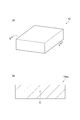
- FIG. 1 is a schematic perspective view of a permanent magnet 10 according to an embodiment of the present invention
- FIG. 10 is a schematic diagram of a cross section 10cs of FIG.
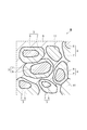
- FIG. 2 is an enlarged view of a part II of the cross section 10cs of the permanent magnet 10 shown in FIG.
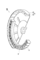
- FIG. 3 is a schematic perspective view of a rotating machine according to an embodiment of the present invention.
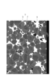
- FIG. 4 is a photograph of a cross section of the permanent magnet of Example 1.
- the permanent magnet according to the present invention may be a sintered magnet or a hot-worked magnet.
- the permanent magnet according to the present invention may be a rare earth magnet.
- the permanent magnet 10 includes a plurality of main phase particles 3 and a grain boundary phase 9 located between the main phase particles 3.
- the permanent magnet 10 may be a sintered body composed of a large number of main phase particles 3 that are sintered together via the grain boundary phase 9.
- Each main phase particle 3 has a core 5 and a shell 7 covering the core 5.
- the shell 7 may cover a part or the whole of the core 5.
- the permanent magnet 10 may include magnetic particles 11 that do not include the core 5 and the shell 7.
- Each main phase particle 3 contains at least a rare earth element R, a transition metal element T, and boron (B).
- the rare earth element R contains at least Nd (neodymium), Y (yttrium), and Ce (cerium). That is, a part of Nd is substituted with Y and Ce.
- the transition metal element T contains at least Fe (iron).
- the transition metal element T may contain Fe and Co (cobalt). That is, a part of the Fe may be replaced with Co.
- Each main phase particle 3 may contain carbon (C) in addition to boron. That is, a part of the above B may be replaced with C.
- the main phase particle 3 may contain R 2 T 14 M as a main phase.
- the element M may be only B.
- the element M may be B and C.
- R 2 T 14 M may be represented as Nd 2 -xy Y x Ce y Fe 14 -s Co s B 1 -t C t .
- x + y is greater than 0 and less than 2.
- x is greater than 0 and less than 2.
- y is greater than 0 and less than 2.
- s is 0 or more and less than 14.
- t is 0 or more and less than 1.
- the main phase particle 3 may contain Nd 2 Fe 14 B.
- the main phase particle 3 may include Y 2 Fe 14 B.
- the main phase particles 3 may include Ce 2 Fe 14 B.
- the Y content (concentration) in the core 5 is expressed as [Y] CORE atomic%.
- the Y content (concentration) in the shell 7 is expressed as [Y] SHELL atomic%.
- the Ce content (concentration) in the core 5 is expressed as [Ce] CORE atomic%.
- the Ce content in the shell 7 is expressed as [Ce] SHELL atomic%.
- [Y] CORE is larger than [Y] SHELL
- [Ce] SHELL is larger than [Ce] CORE .
- the permanent magnet according to the present embodiment 10 can have a balanced residual magnetic flux density and coercivity.
- the present inventors consider that the reason is as follows. However, the reason why the effect of the present invention is obtained is not limited to the following.
- the saturation magnetization Is of Nd 2 Fe 14 B is 1.60 T
- the saturation magnetization Is of Y 2 Fe 14 B is 1.42 T
- the saturation magnetization Is of Ce 2 Fe 14 B is 1.17 T. That is, the saturation magnetization Is of Y 2 Fe 14 B is larger than the saturation magnetization Is of Ce 2 Fe 14 B, and the difference in saturation magnetization Is between Nd 2 Fe 14 B and Y 2 Fe 14 B is Nd 2 It is smaller than the difference in saturation magnetization Is between Fe 14 B and Ce 2 Fe 14 B.
- the amount of decrease in saturation magnetization Is caused by substituting Nd in the main phase (Nd 2 Fe 14 B) with Y is smaller than the amount of decrease in saturation magnetization Is caused by substituting Nd in the main phase with Ce. Is also small. That is, even if the number of Nd substituted with Y is larger than the number of Nd substituted with Ce, the residual magnetic flux density Br of the permanent magnet with Nd substituted with Y is Nd replaced with Ce. This is equivalent to the residual magnetic flux density Br of the permanent magnet. Therefore, by replacing Nd with Y, the amount of Nd used can be reduced and the raw material cost of the permanent magnet can be reduced while suppressing a decrease in the residual magnetic flux density Br as compared with the case where Nd is replaced with Ce.
- the anisotropic magnetic field Ha of Y 2 Fe 14 B is smaller than the anisotropic magnetic field Ha of Ce 2 Fe 14 B, and the anisotropic magnetic field Ha between Nd 2 Fe 14 B and Y 2 Fe 14 B. Is larger than the difference in the anisotropic magnetic field Ha between Nd 2 Fe 14 B and Ce 2 Fe 14 B.
- the anisotropic magnetic field Ha of Nd 2 Fe 14 B is 67 kOe
- the anisotropic magnetic field Ha of Y 2 Fe 14 B is 20 kOe
- the anisotropic magnetic field Ha of Ce 2 Fe 14 B is 30 kOe.
- the amount of decrease in the anisotropic magnetic field Ha caused by replacing Nd with Y is larger than the amount of decrease in the anisotropic magnetic field Ha caused by replacing Nd with Ce.
- [Ce] SHELL is larger than [Ce] CORE , Nd in the shell 7 is more easily replaced with Ce than Nd in the core 5. Due to the increase in the number of Nd substituted with Ce in the shell 7, the anisotropic magnetic field Ha of the shell 7 becomes larger than the anisotropic magnetic field Ha of the core 5. The decrease in HcJ is suppressed.
- [Y] CORE / [Y] SHELL may be 1.05 or more and 1.22 or less, and [Ce] SHELL / [Ce] CORE may be 1.04 or more and 1.20 or less.
- [Y] CORE / [Y] SHELL and [Ce] SHELL / [Ce] CORE With the increase in [Y] CORE / [Y] SHELL and [Ce] SHELL / [Ce] CORE , the difference in the respective contents of Y and Ce between the core 5 and the shell 7 increases, and the residual magnetic flux density Br and The decrease in the coercive force Hc is easily suppressed, more Nd is easily replaced with Y and Ce, and the raw material cost of the permanent magnet 10 is easily reduced.
- [Y] CORE / [Y] SHELL When [Y] CORE / [Y] SHELL is 1.22 or less and [Ce] SHELL / [Ce] CORE is 1.20 or less, Ce hardly penetrates into the entire core 5. As a result, the effects of different contents of Y and Ce substituting Nd between the core 5 and the shell 7 are likely to appear.
- [Y] CORE / [Y] SHELL may be 1.05 to 1.33, and [Ce] SHELL / [Ce] CORE may be 1.04 to 1.30.
- [Y] CORE / [Y] SHELL may be 1.22 or more and 1.33 or less, and [Ce] SHELL / [Ce] CORE may be 1.20 or more and 1.30 or less.
- [Y] CORE / [Y] SHELL may be 1.05 or more and 1.13 or less, and [Ce] SHELL / [Ce] CORE may be 1.04 or more and 1.12 or less.
- the grain boundary phase 9 may include a phase containing R and T intermetallic compounds. Intermetallic compounds may be, for example, RT 2.
- RT 2 may be expressed as Nd 1- ⁇ - ⁇ Y ⁇ Ce Ce ⁇ Fe 2- ⁇ Co ⁇ . Each of ⁇ and ⁇ is 0 or more, and ⁇ + ⁇ is 0 or more and 1 or less. ⁇ is 0 or more and 2 or less.
- RT 2 may be, for example, NdFe 2 , YFe 2 or CeFe 2 .
- the grain boundary phase 9 may comprise Laves (Laves) phase consisting RT 2.
- the grain boundary phase 9 may include an R-rich phase having a larger R content than the main phase particles 3 and the Laves phase.
- the grain boundary phase 9 may include a phase containing YN (yttrium nitride) or a phase consisting of YN.
- the grain boundary phase 9 may include a foreign phase other than the above.
- the heterogeneous phase may include at least one selected from the group consisting of O (oxygen), C (carbon), and N (nitrogen), for example.
- the content of impurity elements such as O, C and N in the permanent magnet 10 is preferably as small as possible.
- the content of O in the permanent magnet 10 may be 5000 ppm by mass or less, or 3000 ppm by mass or less.
- the N content in the permanent magnet 10 may be 920 mass ppm or more and 2100 mass ppm or less. Even if the N content is 920 mass ppm or more and 2100 mass ppm or less, according to the present embodiment, the reduction of the residual magnetic flux density Br and the coercive force Hc of the entire permanent magnet 10 due to the substitution of Nd is suppressed.
- the content of the rare earth element R in the permanent magnet 10 may be, for example, 11 atomic% or more and 20 atomic% or less.
- the permanent magnet 10 tends to contain a sufficient amount of the main phase (R 2 T 14 B phase), and a soft magnetic material such as ⁇ -Fe is contained in the permanent magnet 10. Difficult to precipitate. As a result, the permanent magnet 10 tends to have a large coercive force.
- the volume ratio of the main phase (R 2 T 14 B phase) in the permanent magnet 10 is sufficiently high, and the permanent magnet 10 tends to have a large residual magnetic flux density.
- the permanent magnet 10 includes, as rare earth elements R, Sc (scandium), La (lanthanum), Pr (praseodymium), Sm (samarium), Eu (europium), Gd (gadolinium), Ho (holmium), Dy (dysprosium) and It may further include at least one selected from the group consisting of Tb (terbium).
- R rare earth elements
- Sc scandium
- La lanthanum
- Pr praseodymium
- Sm sinarium
- Eu europium
- Gd gadolinium
- Ho holmium
- Dy dysprosium
- It may further include at least one selected from the group consisting of Tb (terbium).
- the total content of Ho, Dy, and Tb may be 1 atomic% or less with respect to the entire permanent magnet 10.
- the total content of other rare earth elements excluding Nd, Y and Ce may be 1 atomic% or less with respect to the entire permanent magnet 10.
- the content of B in the permanent magnet 10 may be 4 atomic% or more and 7 atomic% or less.
- the content of B is 4 atomic% or more, the permanent magnet 10 tends to have a large coercive force.
- the B content is 7 atomic% or less, the permanent magnet 10 tends to have a large residual magnetic flux density.
- the content of Fe in the permanent magnet 10 may be 70 atomic% or more and 85 atomic% or less.
- the Co content in the permanent magnet 10 may be 0.0 atomic% or more and 4.0 atomic% or less. Co increases the Curie temperature of the permanent magnet 10 or improves the corrosion resistance of the grain boundary phase 9.
- the permanent magnet 10 may include one of Al and Cu.
- the permanent magnet 10 may include both Al and Cu.
- the total content of Al and Cu in the permanent magnet 10 may be 0.01 atomic% or more and 1.2 atomic% or less. When the total content of Al and Cu is 0.01 atomic percent or more and 1.2 atomic percent or less, the coercive force, corrosion resistance, and temperature characteristics of the permanent magnet 10 are easily improved.
- the permanent magnet 10 is, for example, Ni (nickel), Zr (zirconium), Ti (titanium), Bi (bismuth), Sn (tin), Ga (gallium), Nb (niobium), Ta (tantalum), Si (silicon) ), V (vanadium), Ag (silver), and Ge (germanium).
- the analysis method of the permanent magnet 10 is not limited.
- the permanent magnet 10 includes a scanning electron microscope (SEM), an electron beam microanalyzer (EPMA), an energy dispersive X-ray spectrometer (EDS), a fluorescent X-ray (XRF) analysis method, and an ICP (Inductively Coupled Plasma) emission analysis method. Analysis may be performed by inert gas melting-non-dispersive infrared absorption method, combustion in an oxygen stream-infrared absorption method, or inert gas melting-thermal conductivity method.
- SEM scanning electron microscope
- EPMA electron beam microanalyzer
- EDS energy dispersive X-ray spectrometer
- XRF fluorescent X-ray
- ICP Inductively Coupled Plasma
- the starting material may be a single element (single metal) of the above element or an alloy containing the above element.
- the starting material may be, for example, pure neodymium, pure yttrium, pure cerium, pure iron, and an alloy of iron and boron (iron boride).
- a raw material alloy may be produced from the above starting materials by the following strip casting method, high frequency induction melting method, and other melting methods.
- a raw material alloy may be produced from a starting material by a reduction diffusion method.
- a melting method such as a strip casting method may be performed in a non-oxidizing atmosphere.
- the non-oxidizing atmosphere may be, for example, a vacuum or an inert gas such as Ar.
- the starting material is melted in a non-oxidizing atmosphere to produce a molten metal (melting material alloy).
- the molten metal is poured onto the surface of the rotating roll in a non-oxidizing atmosphere.
- the molten metal is rapidly cooled on the surface of the roll and solidified to obtain a thin plate or flake (scale piece) of the raw material alloy.
- the molten metal may be discharged onto the surface of the water-cooled copper plate.
- An alloy formed by quenching and solidifying the molten metal has a homogeneous structure with a crystal grain size of 1 to 50 ⁇ m.
- the raw material alloy that has undergone rapid cooling and solidification is separated into main phase particles having an R 2 T 14 M structure and grain boundary phases other than the main phase particles.
- Nd is easily dispersed uniformly in the main phase particles and the grain boundary phase.
- Y tends to be unevenly distributed in the main phase particles.
- Ce becomes an RFe 2 phase (CeFe 2 ) and is easily dispersed in the grain boundary phase, and the Ce content in the grain boundary phase tends to be larger than the Ce content in the main phase particles.
- an alloy that has undergone rapid cooling and solidification still has no core and shell.
- a permanent magnet may be produced using one type of raw material alloy obtained by the above method.
- the permanent magnet may be produced by a mixing method using a plurality of kinds of raw material alloys having different compositions. For example, a permanent magnet using a first alloy containing R 2 T 14 M crystal grains as a main component (an alloy having a small R content) and a second alloy having a larger R content than the first alloy. May be produced.
- the raw material alloy may be pulverized by, for example, hydrogen pulverization.
- hydrogen pulverization the raw material alloy is placed in a hydrogen atmosphere, and the raw material alloy is made to store hydrogen.
- the raw material alloy occludes hydrogen, the volume of the raw material alloy expands.
- the hydrogenation reaction of the metal contained in the raw material alloy occurs, and the raw material alloy becomes brittle.
- cracks occur in the raw material alloy, and the raw material alloy is pulverized.
- the particle size of the coarse powder may be, for example, 10 to 1000 ⁇ m.
- the hydrogen releasing treatment a part of hydrogen is released from the raw material alloy by holding the raw material alloy in a vacuum atmosphere for a predetermined time while heating at a predetermined temperature.
- the heating temperature of the hydrogen releasing treatment may be 200 ° C. or higher, desirably 350 ° C. or higher.
- the holding time may be appropriately adjusted according to the relationship with the heating temperature, the weight of the raw material alloy, the thickness, and the target value of the hydrogen residual amount. Hydrogen remaining in the raw material alloy after the hydrogen releasing treatment may be completely removed in a sintering process described later.
- fine powder is obtained from the raw powder of the raw material alloy.
- the raw material alloy may be pulverized using a jet mill.
- the average particle size of the raw material alloy may be adjusted to 2.5 to 6 ⁇ m, desirably 3 to 5 ⁇ m.
- wet pulverization of the raw material alloy may be performed.
- the specific means of wet grinding may be a ball mill or a wet attritor.
- the average particle diameter of the raw material alloy may be adjusted to 1.5 ⁇ m or more and 5 ⁇ m or less, desirably 2 ⁇ m or more and 4.5 ⁇ m or less.
- the raw material alloy since the raw material alloy is pulverized in the dispersion medium, it is difficult for the raw material alloy to come into direct contact with oxygen in the atmosphere, and it is easy to obtain a fine powder with a small oxygen content.
- fatty acids, fatty acid derivatives, and other hydrocarbons may be added to the fine powder.
- the hydrocarbon added to the fine powder is, for example, at least one selected from the group consisting of zinc stearate, calcium stearate, aluminum stearate, stearic acid amide, oleic acid amide, ethylenebisisostearic acid amide, paraffin, and naphthalene. It may be.
- the content of the hydrocarbon in the fine powder may be 0.01% by mass or more and 0.3% by mass or less.
- a compact is obtained by applying pressure to the fine powder in the mold while applying a magnetic field to the fine powder in the mold.
- the pressure exerted on the fine powder may be 30 MPa or more and 300 MPa or less.
- the strength of the magnetic field applied to the fine powder may be 960 kA / m or more and 1600 kA / m or less.
- the magnetic field may be a static magnetic field or a pulsed magnetic field. A magnetic field and a pulsed magnetic field may be used in combination.
- the relative density of the shaped body may be 40-60%.
- the compact is heated while supplying a small amount of nitrogen gas to the compact under vacuum.
- a sintered body permanent magnet 10
- the mechanism by which the core-shell structure of the main phase particles 3 is formed in the sintering process is as follows.
- the mechanism by which the aschel structure is formed is not limited to the following.
- Y is distributed substantially uniformly in each main phase particle, and the Y content in the main phase particles is much higher than the Y content in the grain boundary phase. small.
- Ce is RFe 2 phase (CeFe 2 ) and dispersed in the grain boundary phase, and the Ce content in the grain boundary phase is higher than the Ce content in the main phase particles.
- Y hydrogenated by the occlusion of hydrogen described above becomes nitride and stabilizes at about 1000 ° C.
- the temperature at which the CeFe 2 phase transitions to the liquid phase is 925 ° C. Therefore, when the molded body is heated at 900 ° C.
- the transition of the RFe 2 phase containing Ce into the liquid phase and the dehydrogenation and nitridation of Y proceed simultaneously.
- Y escapes from the main phase (R 2 T 14 M) and becomes YN (yttrium nitride) and stabilizes in the grain boundary phase.
- a part of Ce enters the main phase from the grain boundary phase (RFe 2 phase) and constitutes a part of the main phase (for example, Ce 2 Fe 14 B phase).
- the Y content in the shell 7 decreases, and the Ce content in the shell 7 increases. That is, as a result of the movement of Y and Ce between the main phase and the grain boundary phase, [Y] CORE becomes larger than [Y] SHELL , and [Ce] SHELL becomes larger than [Ce] CORE .
- the molded body is heated at 900 ° C. or higher and 1100 ° C. or lower under high vacuum to be additionally sintered. By additional sintering, the sintered body becomes denser and the sintering process is completed.
- the sintering time with the supply of nitrogen gas and the additional sintering time are determined by the composition of the target permanent magnet 10, the grinding method of the raw material alloy, the average particle size and particle size distribution of the raw material alloy, and the target Y And may be adjusted as appropriate according to the amount of mutual diffusion of Ce.
- the sintering time with supply of nitrogen gas may be 0.5 hours or more and 4 hours or less. When the sintering time with the supply of nitrogen gas is less than 30 minutes, the mutual diffusion of Y and Ce between the main phase particles and the grain boundary phase becomes insufficient, and a desired core-shell structure cannot be obtained.
- the additional sintering time may be 3 hours or more and 12 hours or less. When the additional sintering time is less than 3 hours, it is difficult to obtain a dense sintered body and the residual magnetic flux density of the permanent magnet tends to be small. When the additional sintering time is longer than 12 hours, grain growth proceeds excessively in the molded body, and the coercive force of the permanent magnet tends to be small.
- the sintered body may be subjected to an aging treatment.
- the coercive force of the permanent magnet is increased by the aging treatment.
- the aging treatment may be carried out in two stages. In the aging treatment, for example, the sintered body may be heated in the vicinity of 800 ° C. and then the sintered body may be heated in the vicinity of 600 ° C. for a predetermined time.
- the coercive force of the sintered body tends to increase due to the aging treatment at around 800 ° C.
- the aging treatment is performed in one stage, the coercive force of the sintered body is likely to increase due to the aging treatment near 600 ° C.
- the rotating machine according to the present embodiment includes the permanent magnet 10a as a permanent magnet.
- An example of the internal structure of the rotating machine is shown in FIG.
- the rotating machine 200 according to the present embodiment is a permanent magnet synchronous rotating machine (SPM rotating machine).
- the rotating machine 200 includes a cylindrical rotor 50 and a stator 30 disposed inside the rotor 50.
- the rotor 50 includes a cylindrical core 52 and a plurality of permanent magnets 10 a arranged along the inner peripheral surface of the core 52.
- the plurality of permanent magnets 10 a are arranged so that N poles and S poles are alternately arranged along the inner peripheral surface of the core 52.
- the stator 30 has a plurality of coils 32 provided along the outer peripheral surface thereof.
- the coil 32 and the permanent magnet 10a are arranged so as to face each other.
- the rotating machine 200 may be an electric motor.
- the electric motor converts electrical energy into mechanical energy by the interaction between the field generated by the electromagnet generated by energizing the coil 32 and the field generated by the permanent magnet 10a.
- the rotating machine 200 may be a generator.
- the generator converts mechanical energy into electrical energy by the interaction (electromagnetic induction) between the field and the coil 32 by the permanent magnet 10a.
- the rotating machine 200 that functions as an electric motor may be, for example, a permanent magnet DC motor, a linear synchronous motor, a permanent magnet synchronous motor (SPM motor, IPM motor), or a reciprocating motor.
- the motor that functions as the reciprocating motor may be, for example, a voice coil motor or a vibration motor.
- the rotating machine 200 that functions as a generator may be, for example, a permanent magnet synchronous generator, a permanent magnet commutator generator, or a permanent magnet AC generator.
- the rotating machine 200 may be used for automobiles, industrial machines, household appliances, and the like.
- an additional process for the permanent magnet may be performed using a grain boundary diffusion method.
- the permanent magnet according to the present invention may be manufactured by a hot working method, a film forming method, a spark plasma sintering method, or the like.
- Example 1 [Production of permanent magnets] As starting materials, pure neodymium, pure yttrium, pure cerium, pure iron, an alloy of iron and boron, pure aluminum, pure copper and pure cobalt were prepared. Each starting material was weighed and mixed so that the composition of the permanent magnet matched the composition shown in Table 1 below. In Table 1 below, the numerical value described after each element symbol is the content (unit: atomic%) of each element in the permanent magnet.
- a thin plate of a raw material alloy was produced from the above mixture of starting materials by the above-described strip casting method.
- the raw material alloy thin plate was heated at 400 ° C. for 3 hours under a hydrogen atmosphere of 1 atm to occupy the raw material alloy and pulverize the raw material alloy.
- the pulverized raw material alloy was heated at 300 ° C. for 30 minutes under vacuum.
- Oleic acid amide (lubricant) was added to the alloy powder obtained by the hydrogen releasing treatment.
- the alloy powder was pulverized with a jet mill in high-pressure nitrogen gas to obtain a fine alloy powder.
- alloy fine powder was supplied into the mold. And while applying a static magnetic field to the fine powder in a metal mold
- the pressure exerted on the fine powder was 40 MPa.
- the strength of the static magnetic field applied to the fine powder was 15 KOe (about 1194 kA / m).
- the magnetic field direction was perpendicular to the pressing direction.
- the dimension of the molded body was 20 mm ⁇ 18 mm ⁇ 13 mm.
- An aging treatment was applied to the sintered body obtained in the molding process.
- the sintered body was heated at 850 ° C. for 1 hour, and then the sintered body was heated at 530 ° C. for 1 hour.
- a sample for analysis was produced by embedding a permanent magnet in an epoxy resin and curing the epoxy resin. The sample was cut, and the cross section of the sample (permanent magnet embedded in the resin) was polished using polishing paper, buffs, and diamond abrasive grains. Water was not used for polishing to prevent corrosion of the sample.
- the cross section of the polished sample was analyzed with a scanning electron microscope and an electron beam microanalyzer.
- the results of the analysis were as follows.
- the permanent magnet has innumerable main phase particles 3 each having a core 5 and a shell 7 covering the core 5. And the grain boundary phase 9 located between the main phase particles 3.
- Each main phase particle 3 was confirmed to contain at least Nd, Y, Ce, Fe, Co, and B.
- a cross section of the permanent magnet of Example 1 taken by SEM is shown in FIG. Thirty main phase particles 3 having a core-shell structure were randomly selected, and the compositions of the core 5 and the shell 7 of each main phase particle 3 were analyzed. The content of each element described below is an average value of the content measured in 30 main phase particles 3.
- the Y content ([Y] CORE ) in the core 5 is shown in Table 2 below.
- the Y content ([Y] SHELL ) in the shell 7 is shown in Table 2 below.
- the Ce content ([Ce] CORE ) in the core 5 is shown in Table 2 below.
- the Ce content ([Ce] SHELL ) in the shell 7 is shown in Table 2 below.
- [Y] CORE / [Y] SHELL is shown in Table 2 below.
- [Y] c / [Y] s described in Table 2 means [Y] CORE / [Y] SHELL .
- [Ce] SHELL / [Ce] CORE is shown in Table 2 below.
- [Ce] s / [Ce] c described in Table 2 means [Ce] SHELL / [Ce] CORE .
- [Y] CORE / [Y] SHELL was greater than 1. That is, [Y] CORE was larger than [Y] SHELL . Actual [Ce] SHELL / [Ce] CORE was greater than 1. That is, [Ce] SHELL was larger than [Ce] CORE .
- the content of N in the permanent magnet was measured by an inert gas melting-thermal conductivity method.
- the N content ([N]) in the permanent magnet is shown in Table 2 below.
- the residual magnetic flux density Br and the coercive force HcJ of the permanent magnet of Example 1 were measured with a BH tracer.
- the residual magnetic flux density Br and the coercive force HcJ of Example 1 are shown in Table 2 below.
- the residual magnetic flux density Br is preferably 1.200 T or more.
- the coercive force HcJ is preferably 950 kA / m or more.
- Examples 2 to 4 In the production of each of the permanent magnets of Examples 2 to 4, each starting material was weighed so that the composition of the permanent magnet matched the composition shown in Table 1 below. In each of the sintering steps of Examples 2 to 4, the flow rate of nitrogen gas (N 2 flow rate) was adjusted to the value shown in Table 1 below. Except for these items, permanent magnets of Examples 2 to 4 were produced in the same manner as in Example 1.
- Example 2 The permanent magnets of Examples 2 to 4 were analyzed in the same manner as in Example 1. The analysis results of the permanent magnets of Examples 2 and 3 are shown in Table 2 below.
- [Y] CORE / [Y] SHELL was larger than 1. That is, in any of Examples 2 to 4, [Y] CORE was larger than [Y] SHELL .
- [Ce] SHELL / [Ce] CORE was larger than 1. That is, in any of Examples 2 to 4, [Ce] SHELL was larger than [Ce] CORE .
- the permanent magnet according to the present invention is used, for example, in a rotating machine for automobiles.
Landscapes
- Engineering & Computer Science (AREA)
- Chemical & Material Sciences (AREA)
- Mechanical Engineering (AREA)
- Manufacturing & Machinery (AREA)
- Materials Engineering (AREA)
- Metallurgy (AREA)
- Organic Chemistry (AREA)
- Crystallography & Structural Chemistry (AREA)
- Inorganic Chemistry (AREA)
- Power Engineering (AREA)
- Hard Magnetic Materials (AREA)
- Powder Metallurgy (AREA)
Abstract
Ndの代替元素としてY及びCeを含む永久磁石の中でも残留磁束密度及び保磁力のバランスのとれた永久磁石が提供される。永久磁石10は、希土類元素R、遷移金属元素T、及びホウ素を含む主相粒子3を備え、希土類元素Rは、少なくともNd、Y及びCeを含み、遷移金属元素Tは、少なくともFeを含み、主相粒子3が、コア5と、コア5を覆うシェル7と、を有し、コア5におけるYの含有量が[Y]CORE原子%であり、シェル7におけるYの含有量が[Y]SHELL原子%であり、コア5におけるCeの含有量が[Ce]CORE原子%であり、シェル7におけるCeの含有量が[Ce]SHELL原子%であり、[Y]COREが[Y]SHELLよりも大きく、[Ce]SHELLが[Ce]COREよりも大きい。
Description
本発明は、永久磁石及び回転機に関する。
主相としてNd2Fe14B相を含む永久磁石は、残留磁束密度Br、キュリー温度Tc、及び異方性磁界Ha等の磁気特性のバランスが良いことから、様々な技術分野において実用されている。例えば自動車の回転機(モーター)に用いる永久磁石は、高温環境下で使用されることから、大きい保磁力(HcJ)が要求される。永久磁石の保磁力は、Dy又はTb等の重希土類元素の添加により増加する。しかし、重希土類元素は高価であり、その供給量が安定しないので、重希土類元素を使用しない永久磁石が望まれる。重希土類元素を使用しない永久磁石を構成する元素のうち、Ndが最も高価であり、原材料費の大部分をNdの価格が占める。したがって、Ndの使用量を低減するために、Ndの一部をY、La又はCe等の安価な元素に置換する研究が行われている。(下記特許文献1参照。)
しかしながら、Y、La又はCe等の安価な元素から構成される主相の飽和磁化Is及び異方性磁界Haは、Nd2Fe14B相と比較して著しく小さい。そのため、Ndの一部がY、La又はCe等で置換された永久磁石の残留磁束密度Br及び保磁力HcJは、Ndが置換されていない場合に比べて著しく小さい。
本発明は、上記事情に鑑みてなされたものであり、Ndの代替元素としてY及びCeを含む永久磁石の中でも残留磁束密度及び保磁力のバランスのとれた永久磁石、及び当該永久磁石を備える回転機を提供することを目的とする。
本発明の一側面に係る永久磁石は、希土類元素R、遷移金属元素T、及びホウ素を含む主相粒子を備え、希土類元素Rは、少なくともNd、Y及びCeを含み、遷移金属元素Tは、少なくともFeを含み、主相粒子が、コアと、コアを覆うシェルと、を有し、コアにおけるYの含有量が[Y]CORE原子%であり、シェルにおけるYの含有量が[Y]SHELL原子%であり、コアにおけるCeの含有量が[Ce]CORE原子%であり、シェルにおけるCeの含有量が[Ce]SHELL原子%であり、[Y]COREが[Y]SHELLよりも大きく、[Ce]SHELLが[Ce]COREよりも大きい。
本発明の一側面においては、[Y]CORE/[Y]SHELLが1.05以上1.22以下であってよく、[Ce]SHELL/[Ce]COREが1.04以上1.20以下であってよい。
本発明の一側面に係る回転機は、上記永久磁石を備える。
本発明によれば、Ndの代替元素としてY及びCeを含む永久磁石の中でも残留磁束密度及び保磁力のバランスのとれた永久磁石、及び当該永久磁石を備える回転機が提供される。
以下、場合により図面を参照して、本発明の好適な実施形態について説明する。ただし、本発明は下記実施形態に何ら限定されるものではない。図面において、同一又は同等の構成要素には同一の符号を付す。以下に記載の単位(kOe)は、「×(103/4π)×(kA/m)」と等価である。本発明に係る永久磁石は、焼結磁石、又は熱間加工磁石であってよい。本発明に係る永久磁石は、希土類磁石であってよい。
本実施形態に係る永久磁石10の全体は、図1中の(a)に示される。永久磁石10の断面10csは、図1中の(b)に示される。図2は、永久磁石10の断面10csの一部IIの拡大図である。図2に示されるように、実施形態に係る永久磁石10は、複数の主相粒子3と、主相粒子3の間に位置する粒界相9と、を備える。例えば、永久磁石10は、粒界相9を介して互いに焼結した多数の主相粒子3から構成される焼結体であってよい。各主相粒子3は、コア5と、コア5を覆うシェル7と、を有する。シェル7は、コア5の一部又は全体を覆っていてよい。永久磁石10は、コア5及びシェル7を備えない磁性粒子11を含んでよい。
各主相粒子3は、少なくとも希土類元素R、遷移金属元素T、及びホウ素(B)を含む。希土類元素Rは、少なくともNd(ネオジム)、Y(イットリウム)及びCe(セリウム)を含む。つまり、Ndの一部が、Y及びCeで置換されている。遷移金属元素Tは、少なくともFe(鉄)を含む。遷移金属元素Tは、FeとCo(コバルト)とを含んでよい。つまり、上記のFeの一部がCoで置換されてよい。各主相粒子3は、ホウ素に加えて炭素(C)を含んでよい。つまり、上記のBの一部がCで置換されてよい。主相粒子3は、主相としてR2T14Mを含んでよい。元素MはBのみであってよい。元素Mは、B及びCであってもよい。換言すれば、R2T14Mは、Nd2-x-yYxCeyFe14-sCosB1-tCtと表されてよい。x+yは、0より大きく2未満である。xは、0より大きく2未満である。yは、0より大きく2未満である。sは、0以上14未満である。tは、0以上1未満である。例えば、主相粒子3は、Nd2Fe14Bを含んでよい。例えば、主相粒子3は、Y2Fe14Bを含んでもよい。例えば、主相粒子3は、Ce2Fe14Bを含んでもよい。
コア5におけるYの含有量(濃度)は、[Y]CORE原子%と表される。シェル7におけるYの含有量(濃度)は、[Y]SHELL原子%と表される。コア5におけるCeの含有量(濃度)は、[Ce]CORE原子%と表される。シェル7におけるCeの含有量は、[Ce]SHELL原子%と表される。[Y]COREは[Y]SHELLよりも大きく、[Ce]SHELLは[Ce]COREよりも大きい。[Y]COREが[Y]SHELLよりも大きく、且つ[Ce]SHELLが[Ce]COREよりも大きいため、Ndの代替元素としてY及びCeを含む永久磁石の中でも、本実施形態に係る永久磁石10は、バランスの良い残留磁束密度及び保磁力を有することができる。その理由は以下の通りである、と本発明者らは考える。ただし、本発明の効果が得られる理由は以下に限定されない。
Nd2Fe14Bの飽和磁化Isは1.60Tであり、Y2Fe14Bの飽和磁化Isは1.42Tであり、Ce2Fe14Bの飽和磁化Isは1.17Tである。つまり、Y2Fe14Bの飽和磁化Isは、Ce2Fe14Bの飽和磁化Isよりも大きく、Nd2Fe14BとY2Fe14Bとの間の飽和磁化Isの差は、Nd2Fe14BとCe2Fe14Bとの間の飽和磁化Isの差よりも小さい。したがって、主相(Nd2Fe14B)のNdをYで置換することに因る飽和磁化Isの減少量は、主相のNdをCeで置換することに因る飽和磁化Isの減少量よりも小さい。すなわち、Yで置換されたNdの数が、Ceで置換されたNdの数よりも多い場合であっても、NdがYで置換された永久磁石の残留磁束密度Brは、NdがCeで置換された永久磁石の残留磁束密度Brと同等である。したがって、NdをYで置換することにより、NdをCeで置換する場合に比べて、残留磁束密度Brの減少を抑制しながら、Ndの使用量を低減して、永久磁石の原材料費を低減することができる。一方、Y2Fe14Bの異方性磁界Haは、Ce2Fe14Bの異方性磁界Haよりも小さく、Nd2Fe14BとY2Fe14Bとの間の異方性磁界Haの差は、Nd2Fe14BとCe2Fe14Bとの間の異方性磁界Haの差よりも大きい。Nd2Fe14Bの異方性磁界Haは67kOeであり、Y2Fe14Bの異方性磁界Haは20kOeであり、Ce2Fe14Bの異方性磁界Haは30kOeである。したがって、NdをYで置換することに因る異方性磁界Haの減少量は、NdをCeで置換することに因る異方性磁界Haの減少量よりも大きい。しかし、[Ce]SHELLが[Ce]COREよりも大きいため、シェル7中のNdは、コア5中のNdに比べて、Ceで置換され易い。シェル7においてCeで置換されるNdの数の増加により、シェル7の異方性磁界Haがコア5の異方性磁界Haよりも大きくなり、主相粒子3同士の磁気分断が起こり、保磁力HcJの低下が抑制される。以上のように、[Y]COREが[Y]SHELLよりも大きいため、コア5中のNdがYで置換され易く、Ndの置換に伴う残留磁束密度Brの低下が抑制される。一方、[Ce]SHELLが[Ce]COREよりも大きいため、シェル7中のNdがCeで置換され易く、Ndの置換に伴う保持力HcJの低下が抑制される。つまり、Ndを置換する各元素の含有量がコア5とシェル7との間で異なることにより、永久磁石全体10の残留磁束密度Br及び保磁力Hcの減少が最小限に抑制されながら、より多くのNdがY及びCeで置換され、永久磁石10の原材料費が低減される。
[Y]CORE/[Y]SHELLは1.05以上1.22以下であってよく、[Ce]SHELL/[Ce]COREは1.04以上1.20以下であってよい。[Y]CORE/[Y]SHELL及び[Ce]SHELL/[Ce]COREの増加に伴い、コア5及びシェル7間でのY及びCeそれぞれの含有量の差が増加し、残留磁束密度Br及び保磁力Hcの減少が抑制され易く、より多くのNdがY及びCeで置換され易く、永久磁石10の原材料費が低減され易い。[Y]CORE/[Y]SHELLが1.22以下であり、[Ce]SHELL/[Ce]COREが1.20以下である場合、Ceがコア5全体へ浸透し難い。その結果、Ndを置換するY及びCeそれぞれの含有量がコア5とシェル7との間で異なることによる効果が発現し易い。[Y]CORE/[Y]SHELLは1.05以上1.33以下であってもよく、[Ce]SHELL/[Ce]COREは1.04以上1.30以下であってもよい。[Y]CORE/[Y]SHELLは1.22以上1.33以下であってもよく、[Ce]SHELL/[Ce]COREは1.20以上1.30以下であってもよい。[Y]CORE/[Y]SHELLは1.05以上1.13以下であってもよく、[Ce]SHELL/[Ce]COREは1.04以上1.12以下であってもよい。
粒界相9は、R及びTの金属間化合物を含む相を含んでよい。金属間化合物は、例えば、RT2であってよい。RT2は、Nd1-γ-δYγCeδFe2-εCoεと表されてよい。γ及びδそれぞれは0以上であり、γ+δは0以上1以下である。εは、0以上2以下である。RT2は、例えば、NdFe2、YFe2又はCeFe2であってよい。粒界相9は、RT2からなるラーベス(Laves)相を含んでよい。粒界相9は、主相粒子3及びラーベス相よりもRの含有量が大きいRリッチ相を含んでよい。粒界相9は、YN(窒化イットリウム)を含む相、又はYNからなる相を含んでよい。粒界相9は、上記外の異相を含んでよい。異相は、例えば、O(酸素)、C(炭素)及びN(窒素)からなる群より選ばれる少なくとも一種を含んでよい。永久磁石10におけるO、C及びN等の不純物元素の含有量は小さいほどよい。永久磁石10におけるOの含有量は5000質量ppm以下、又は3000質量ppm以下であってよい。Oの含有量が小さいほど、希土類元素の酸化物(非磁性成分)が永久磁石10に含まれ難く、永久磁石10の磁気特性が損なわれ難い。永久磁石10におけるNの含有量は、920質量ppm以上2100質量ppm以下であってよい。Nの含有量が920質量ppm以上2100質量ppm以下であっても、本実施形態によれば、Ndの置換に伴う永久磁石全体10の残留磁束密度Br及び保磁力Hcの減少が抑制される。
永久磁石10における希土類元素Rの含有量は、例えば、11原子%以上20原子%以下あってよい。希土類元素Rの含有量が11原子%以上である場合、永久磁石10が十分な量の主相(R2T14B相)を含み易く、α-Fe等の軟磁性体が永久磁石10中に析出し難い。その結果、永久磁石10が大きい保磁力を有し易い。希土類元素Rの含有量が20原子%以下である場合、永久磁石10における主相(R2T14B相)の体積比率が十分に高く、永久磁石10が大きい残留磁束密度を有し易い。
永久磁石10は、希土類元素Rとして、Sc(スカンジウム)、La(ランタン)、Pr(プラセオジム)、Sm(サマリウム)、Eu(ユウロピウム)、Gd(ガドリニウム)、Ho(ホルミウム)、Dy(ジスプロシウム)及びTb(テルビウム)からなる群より選ばれる少なくも一種を更に含んでよい。原材料費を抑制するために、Ho、Dy及びTbの含有量の合計は、永久磁石10全体に対して1原子%以下であってよい。残留磁束密度及び異方性磁界を増加させるために、Nd、Y及びCeを除く他の希土類元素の含有量の合計は、永久磁石10全体に対して1原子%以下であってよい。永久磁石10に含まれる全希土類元素の数に対するNdの数の割合は、40%以上90%以下であってよい。全希土類元素の数に対するNdの数の割合が40%以上である場合、残留磁束密度及び保磁力が増加し易い。全希土類元素の数に対するNdの数の割合が90%以下である場合、原材料費が低減される効果と、残留磁束密度及び保磁力の減少が抑制されるという上記効果とが得られ易い。
永久磁石10におけるBの含有量は、4原子%以上7原子%以下であってよい。Bの含有量が4原子%以上ある場合、永久磁石10が大きい保磁力を有し易い。Bの含有量が7原子%以下ある場合、永久磁石10が大きい残留磁束密度を有し易い。
永久磁石10におけるFeの含有量は、70原子%以上85原子%以下であってよい。永久磁石10におけるCoの含有量は、0.0原子%以上4.0原子%以下であってよい。Coは、永久磁石10のキュリー温度を高めたり、粒界相9の耐食性を向上させたりする。永久磁石10は、Al及びCuのうち一方を含んでよい。永久磁石10は、Al及びCuの両方を含んでもよい。永久磁石10におけるAl及びCuの含有量の合計は、0.01原子%以上1.2原子%以下であってよい。Al及びCuの含有量の合計は、0.01原子%以上1.2原子%以下である場合、永久磁石10の保磁力、耐食性及び温度特性が向上し易い。
永久磁石10は、例えば、Ni(ニッケル)、Zr(ジルコニウム)、Ti(チタン)、Bi(ビスマス)、Sn(錫)、Ga(ガリウム)、Nb(ニオブ)、Ta(タンタル)、Si(ケイ素)、V(バナジウム)、Ag(銀)及びGe(ゲルマニウム)からなる群より選ばれる少なくとも一種を更に含んでよい。
永久磁石10の分析方法は限定されない。永久磁石10は、走査型電子顕微鏡(SEM)、電子線マイクロアナライザ(EPMA)、エネルギー分散型X線分光器(EDS)、蛍光X線(XRF)分析法、ICP(Inductively Coupled Plasma)発光分析法、不活性ガス融解‐非分散型赤外線吸収法、酸素気流中燃焼‐赤外吸収法、又は不活性ガス融解‐熱伝導度法等によって分析されてよい。
(永久磁石の製造方法)
目的とする永久磁石10の組成に一致するように、希土類元素R、遷移金属元素T、及びホウ素を含む一種以上の出発原料を秤量する。出発原料は、上記元素の単体(単体金属)、又は上記元素を含む合金であってよい。出発原料は、例えば、純ネオジム、純イットリウム、純セリウム、純鉄、並びに、鉄及びホウ素の合金(ホウ化鉄)であってよい。下記のストリップキャスト法、高周波誘導溶解法、その他の溶解法により、上記の出発原料から原料合金を作製してよい。還元拡散法によって出発原料から原料合金を作製してもよい。原料合金の酸化を抑制するために、ストリップキャスト法等の溶解法を非酸化雰囲気中で実施してよい。非酸化雰囲気は、例えば、真空、又はAr等の不活性ガスであってよい。
目的とする永久磁石10の組成に一致するように、希土類元素R、遷移金属元素T、及びホウ素を含む一種以上の出発原料を秤量する。出発原料は、上記元素の単体(単体金属)、又は上記元素を含む合金であってよい。出発原料は、例えば、純ネオジム、純イットリウム、純セリウム、純鉄、並びに、鉄及びホウ素の合金(ホウ化鉄)であってよい。下記のストリップキャスト法、高周波誘導溶解法、その他の溶解法により、上記の出発原料から原料合金を作製してよい。還元拡散法によって出発原料から原料合金を作製してもよい。原料合金の酸化を抑制するために、ストリップキャスト法等の溶解法を非酸化雰囲気中で実施してよい。非酸化雰囲気は、例えば、真空、又はAr等の不活性ガスであってよい。
ストリップキャスト法では、上記出発原料を非酸化雰囲気中で溶解して、溶湯(原料合金の融液)を作製する。溶湯を、非酸化雰囲気中で、回転するロールの表面へ出湯(pour)する。溶湯がロールの表面で急冷され、凝固することにより、原料合金の薄板又は薄片(鱗片)が得られる。溶湯の凝固に伴う偏析を抑制するため、溶湯を、水冷銅板の表面へ出湯してもよい。溶湯の急冷及び凝固によって形成された合金は、結晶粒径が1~50μmである均質な組織を有している。急冷及び凝固を経た原料合金は、R2T14M構造を有する主相粒子と、主相粒子以外の粒界相とに、分離している。Ndは、主相粒子と粒界相とに均一に分散し易い。Yは主相粒子中に偏在し易い。一方、CeはRFe2相(CeFe2)となって粒界相中に分散し易く、粒界相におけるCeの含有量は主相粒子におけるCeの含有量よりも大きくなり易い。ただし、急冷及び凝固を経た合金においては、未だコア及びシェルはない。
以上の方法によって得られた一種類の原料合金を用いて、永久磁石を作製してよい。組成が異なる複数種の原料合金を用いる混合法によって、永久磁石を作製してもよい。例えば、R2T14Mの結晶粒を主成分として含む第一合金(Rの含有量が小さい合金)と、第一合金よりもRの含有量が大きい第二合金と、を用いて永久磁石を作製してもよい。
上記の溶解及び急冷によって得られた原料合金を粉砕して、粗粉末を得る。原料合金の粉砕方法は、例えば、水素粉砕であってよい。水素粉砕では、原料合金を水素雰囲気に置いて、原料合金に水素を吸蔵させる。原料合金が水素を吸蔵すると、原料合金の体積が膨張する。また、原料合金に含まれる金属の水素化反応が生じて、原料合金が脆くなる。その結果、原料合金にクラックが生じて、原料合金が粉砕される。粗粉末の粒径は、例えば、10~1000μmであってよい。
水素粉砕において原料合金中の希土類元素が水素を吸蔵し易い温度は、希土類元素の種類によって異なる。本実施形態では、原料合金を300℃以上500℃以下、又は400℃以上500℃以下で加熱しながら、水素を原料合金に吸蔵させる。300℃以上での加熱処理により、Yが効率よく水素を吸蔵するため、Yの酸化が抑制される。つまり、Yが水素化物になることにより、Yの酸化が抑制される。仮にYが水素化されずに酸化された場合、後の焼結工程においてYの酸化物は窒素と反応し難いため、Yの窒化に伴うYの主相粒子から粒界への移動が妨げられる。その結果、[Y]COREが[Y]SHELLよりも大きくなり難い。水素の吸蔵によって原料合金が粉砕された後、永久磁石において不純物として残留する水素を好適な値に調整するために、水素放出処理を実施する。水素放出処理は、真空中又はArガスのフロー下で行う。水素放出処理では、原料合金を、所定の温度で加熱しながら所定の時間にわたって真空雰囲気中に保持することにより、一部の水素が原料合金から放出される。水素放出処理の加熱温度は、200℃以上、望ましくは350℃以上であってよい。保持時間は、加熱温度との関係、原料合金の重量、厚さ、及び水素残留量の目標値に応じて適宜調整されてよい。水素放出処理後に原料合金中に残留する水素は、後述する焼結工程において完全に除去されてよい。本実施形態では、所望のコアシェル構造を得るために、水素残留量を上記の水素吸蔵及び水素放出処理によって調整することが必要である。ただし、所望のコアシェル構造を得ることが可能であるならば、上記の水素吸蔵及び水素放出処理を実施しなくてもよい。
粗粉砕工程に続く微粉砕工程では、原料合金の粗粉末から微粉末を得る。微粉砕工程では、ジェットミルを用いて原料合金を粉砕してよい。ジェットミルの場合、原料合金の平均粒径を、2.5μm以上6μm以下、望ましくは3以上5μm以下に調整してよい。
微粉砕工程では、原料合金の湿式粉砕を実施してもよい。湿式粉砕の具体的な手段は、ボールミル、又は湿式アトライタであってよい。湿式粉砕の場合、原料合金の平均粒径を、1.5μm以上5μm以下、望ましくは2μm以上4.5μm以下に調整してよい。湿式粉砕では、原料合金が分散媒中で粉砕されるため、原料合金が大気中の酸素に直接触れ難く、酸素の含有量が小さい微粉末が得られ易い。
後述される成形工程における微粉末の潤滑性及び配向性を向上するために、脂肪酸、脂肪酸の誘導体、その他の炭化水素を微粉末に添加してよい。微粉末に添加される炭化水素は、例えば、ステアリン酸亜鉛、ステアリン酸カルシウム、ステアリン酸アルミニウム、ステアリン酸アミド、オレイン酸アミド、エチレンビスイソステアリン酸アミド、パラフィン、及びナフタレンからなる群より選ばれる少なくとも一種であってよい。微粉末における上記炭化水素の含有量は、0.01質量%以上0.3質量%以下であってよい。
上記微粉末を金型内へ供給する。金型内の微粉末に磁場を印加しながら、微粉末を金型で加圧することにより、成形体を得る。微粉末に及ぼす圧力は、30MPa以上300MPa)以下であってよい。微粉末に印加される磁場の強さは、960kA/m以上1600kA/m以下であってよい。磁場は静磁場又はパルス磁場であってよい。磁場とパルス磁場を併用してもよい。成形体の相対密度は、40~60%であってよい。
成形工程に続く焼結工程では、真空下において少量の窒素ガスを成形体へ供給しながら、成形体を加熱する。焼結工程により、コアシェル構造を有する複数の主相粒子3を備える焼結体(永久磁石10)が得られる。焼結工程において主相粒子3のコアシェル構造が形成されるメカニズムは以下の通りである、と本発明者らは考える。ただし、アシェル構造が形成されるメカニズムは以下に限定されるわけではない。
上述の通り、焼結工程前の時点では、Yは各主相粒子中に略均一に分布しており、主相粒子におけるYの含有量は、粒界相におけるYの含有量よりもはるかに小さい。また焼結工程前の時点では、CeはRFe2相(CeFe2)となって粒界相中に分散しており、粒界相におけるCeの含有量は、主相粒子におけるCeの含有量よりも大きい。上述の水素の吸蔵によって水素化されたYは、約1000℃において窒化物になって安定化する。一方、CeFe2相が液相に転移する温度は925℃である。したがって、窒素ガスを成形体に供給しながら成形体を900℃以上1050℃以下で加熱すると、Ceを含むRFe2相の液相への転移と、Yの脱水素及び窒化とが同時に進行する。Yの脱水素及び窒化に伴って、Yは主相(R2T14M)から抜け出し、粒界相においてYN(窒化イットリウム)になって安定化する。主相から抜け出したYの代わりに、Ceの一部は粒界相(RFe2相)から主相へ入り込んで、主相の一部(例えば、Ce2Fe14B相)を構成する。以上のような主相と粒界相との間のY及びCeの移動によって、シェル7におけるYの含有量が減少し、シェル7におけるCeの含有量が増加する。つまり、主相と粒界相との間でのY及びCeの移動の結果、[Y]COREが[Y]SHELLよりも大きくなり、[Ce]SHELLが[Ce]COREよりも大きくなる。窒素ガスの成形体への供給を停止した後、高真空下で成形体を900℃以上1100℃以下で加熱して追加的に焼結させる。追加的な焼結によって、焼結体が更に緻密になり、焼結工程が完了する。窒素ガスの供給を伴う焼結時間、及び追加的な焼結時間は、目的とする永久磁石10の組成、原料合金の粉砕方法、原料合金の平均粒径及び粒度分布、並びに、目的とするY及びCeの相互拡散量に応じて、適宜調整されてよい。窒素ガスの供給を伴う焼結時間は、0.5時間以上4時間以下であってよい。窒素ガスの供給を伴う焼結時間が30分未満である場合、主相粒子と粒界相の間でのY及びCeの相互拡散が不十分となり、所望のコアシェル構造が得られない。窒素ガスの供給を伴う焼結時間が4時間よりも長い場合、主相粒子と粒界相の間でのY及びCeの相互拡散が進行し過ぎる。その結果、Ceがシェル7のみならずコア5へ拡散して、主相粒子3全域においてCeの含有量が大きくなり、[Ce]SHELLが[Ce]COREよりも大きくなり難い。追加的な焼結時間は、3時間以上12時間以下であってよい。追加的な焼結時間が3時間未満である場合、緻密な焼結体が得られ難く、永久磁石の残留磁束密度が小さくなり易い。追加的な焼結時間が12時間よりも長い場合、成形体内で粒成長が過度に進行して、永久磁石の保磁力が小さくなり易い。
焼結工程に続いて、焼結体に時効処理を施してよい。永久磁石の保磁力が時効処理によって増加する。時効処理を二段階に分けて実施してよい。時効処理では、例えば、焼結体を800℃近傍で加熱した後、焼結体を600℃近傍で所定の時間加熱してよい。原料合金を混合法によって調製した場合、800℃近傍での時効処理によって焼結体の保磁力が増加し易い。時効処理を一段階で行なう場合、600℃近傍での時効処理によって焼結体の保磁力が増加し易い。
(回転機)
本実施形態に係る回転機は、永久磁石として、上記の永久磁石10aを備える。回転機の内部構造の一例は、図3に示される。本実施形態に係る回転機200は、永久磁石同期回転機(SPM回転機)である。回転機200は、円筒状のロータ50と、ロータ50の内側に配置されるステータ30と、を備えている。ロータ50は、円筒状のコア52と、コア52の内周面に沿って配置された複数の永久磁石10aと、を有している。複数の永久磁石10aは、コア52の内周面に沿ってN極とS極が交互に並ぶように配置されている。ステータ30は、その外周面に沿って設けられた複数のコイル32を有している。コイル32と永久磁石10aとは互いに対面するように配置されている。
本実施形態に係る回転機は、永久磁石として、上記の永久磁石10aを備える。回転機の内部構造の一例は、図3に示される。本実施形態に係る回転機200は、永久磁石同期回転機(SPM回転機)である。回転機200は、円筒状のロータ50と、ロータ50の内側に配置されるステータ30と、を備えている。ロータ50は、円筒状のコア52と、コア52の内周面に沿って配置された複数の永久磁石10aと、を有している。複数の永久磁石10aは、コア52の内周面に沿ってN極とS極が交互に並ぶように配置されている。ステータ30は、その外周面に沿って設けられた複数のコイル32を有している。コイル32と永久磁石10aとは互いに対面するように配置されている。
回転機200は、電動機(モータ)であってよい。電動機は、コイル32への通電によって生成する電磁石による界磁と、永久磁石10aによる界磁と、の相互作用により、電気エネルギーを機械的エネルギーに変換する。回転機200は、発電機(ジェネレータ)であってもよい。発電機は、永久磁石10aによる界磁とコイル32との相互作用(電磁誘導)により、機械的エネルギーを電気的エネルギーに変換する。
電動機(モータ)として機能する回転機200は、例えば、永久磁石直流モータ、リニア同期モータ、永久磁石同期モータ(SPMモータ、IPMモータ)、又は往復動モータであってよい。往復動モータとして機能するモータは、例えば、ボイスコイルモータ、又は振動モータであってよい。発電機(ジェネレータ)として機能する回転機200は、例えば、永久磁石同期発電機、永久磁石整流子発電機、又は永久磁石交流発電機であってよい。回転機200は、自動車、産業機械、又は家庭用電化製品等に用いられてよい。
以上、本発明の好適な実施形態について説明したが、本発明は上記実施形態に限定されるものではない。例えば、粒界拡散法を用いて、永久磁石に対する追加工を行ってもよい。本発明に係る永久磁石は、熱間加工法、成膜法、又は放電プラズマ焼結(Spark Plasma Sintering)法等によって製造されてもよい。
以下では実施例及び比較例により本発明をさらに詳細に説明するが、本発明はこれらの例によって何ら限定されるものではない。
(実施例1)
[永久磁石の作製]
出発原料として、純ネオジム、純イットリウム、純セリウム、純鉄、鉄及びホウ素の合金、純アルミニウム、純銅及び純コバルトを準備した。永久磁石の組成が下記表1に示される組成に一致するように、各出発原料を秤量して、これ等を混合した。下記表1において各元素記号の後に記載されている数値は、永久磁石における各元素の含有量(単位:原子%)である。
[永久磁石の作製]
出発原料として、純ネオジム、純イットリウム、純セリウム、純鉄、鉄及びホウ素の合金、純アルミニウム、純銅及び純コバルトを準備した。永久磁石の組成が下記表1に示される組成に一致するように、各出発原料を秤量して、これ等を混合した。下記表1において各元素記号の後に記載されている数値は、永久磁石における各元素の含有量(単位:原子%)である。
上述のストリップキャスト法により、上記出発原料の混合物から、原料合金の薄板を作製した。原料合金の薄板を、1気圧の水素雰囲気下において、400℃で3時間加熱することにより、水素を原料合金に吸蔵させて、原料合金を粉砕した。続く水素放出処理では、粉砕された原料合金を真空下において300℃で30分加熱した。水素放出処理によって得られた合金粉末にオレイン酸アミド(潤滑剤)を添加した。続いて、高圧の窒素ガス中において合金粉末をジェットミルで粉砕することにより、合金の微粉末を得た。
成形工程では、合金の微粉末を金型内へ供給した。そして、金型内の微粉末に静磁場を印加しながら、微粉末を金型で加圧することにより、成形体を得た。微粉末に及ぼした圧力は、40MPaであった。微粉末に印加された静磁場の強さは、15KOe(約1194kA/m)であった。磁場方向は加圧方向と垂直であった。成形体の寸法は、20mm×18mm×13mmであった。
成形工程に続く焼結工程では、真空下において窒素ガスを成形体へ供給しながら、成形体を1000℃で1時間加熱した。窒素ガスの流量(N2流量)は、下記表1に示される値であった。窒素ガスの供給を停止した後、真空下で成形体を1000℃で3時間加熱して、成形体を追加的に焼結させた。
成形工程において得られた焼結体に対して時効処理を施した。時効処理では、焼結体を850℃で1時間加熱した後、焼結体を530℃で1時間加熱した。
以上の製造方法により、実施例1の永久磁石を得た。
[永久磁石の分析]
永久磁石をエポキシ系樹脂に埋設して、エポキシ系樹脂を硬化することにより、分析用の試料を作製した。試料を切断して、試料(樹脂内に埋設された永久磁石)の断面を、研磨紙、バフ及びダイヤモンド砥粒を用いて研磨した。試料の腐食を防止するために、水を研磨に用いなかった。
永久磁石をエポキシ系樹脂に埋設して、エポキシ系樹脂を硬化することにより、分析用の試料を作製した。試料を切断して、試料(樹脂内に埋設された永久磁石)の断面を、研磨紙、バフ及びダイヤモンド砥粒を用いて研磨した。試料の腐食を防止するために、水を研磨に用いなかった。
研磨された試料の断面を、走査型電子顕微鏡及び電子線マイクロアナライザで分析した。分析の結果は、以下の通りであった。
永久磁石全体の平均的組成は、下記表1に示される組成と一致することが確認された。SEMによって得られた試料の断面の反射電子像と、EPMAによって得られた元素分布像とから、永久磁石は、コア5と、コア5を覆うシェル7と、を有する無数の主相粒子3と、主相粒子3の間に位置する粒界相9と、を含むことが確認された。各主相粒子3は、少なくともNd、Y、Ce、Fe、Co及びBを含むことが確認された。SEMで撮影された実施例1の永久磁石の断面は、図4に示される。コアシェル構造を有する30個の主相粒子3を無作為に選んで、各主相粒子3のコア5及びシェル7それぞれの組成を分析した。以下に記載された各元素の含有量は、30個の主相粒子3において測定された含有量の平均値である。
コア5におけるYの含有量([Y]CORE)は、下記表2に示される。シェル7におけるYの含有量([Y]SHELL)は、下記表2に示される。コア5におけるCeの含有量([Ce]CORE)は、下記表2に示される。シェル7におけるCeの含有量([Ce]SHELL)は、下記表2に示される。[Y]CORE/[Y]SHELLは、下記表2に示される。なお、表2に記載の[Y]c/[Y]sは、[Y]CORE/[Y]SHELLを意味する。[Ce]SHELL/[Ce]COREは、下記表2に示される。表2に記載の[Ce]s/[Ce]cは、[Ce]SHELL/[Ce]COREを意味する。
[Y]CORE/[Y]SHELLは1より大きかった。つまり、[Y]COREは[Y]SHELLよりも大きかった。実[Ce]SHELL/[Ce]COREは1より大きかった。つまり、[Ce]SHELLは[Ce]COREよりも大きかった。
不活性ガス融解-熱伝導度法により、永久磁石におけるNの含有量を測定した。永久磁石におけるNの含有量([N])は、下記表2に示される。
実施例1の永久磁石の残留磁束密度Br及び保磁力HcJを、BHトレーサーによって測定した。実施例1の残留磁束密度Br及び保磁力HcJは、下記表2に示される。残留磁束密度Brは、1.200T以上であることが好ましい。保磁力HcJは、950kA/m以上であることが好ましい。
(実施例2~4)
実施例2~4それぞれの永久磁石の作製では、永久磁石の組成が下記表1に示される組成に一致するように、各出発原料を秤量した。実施例2~4それぞれの焼結工程では、窒素ガスの流量(N2流量)を、下記表1に示される値に調整した。これらの事項を除いて実施例1と同様の方法で、実施例2~4それぞれの永久磁石を作製した。
実施例2~4それぞれの永久磁石の作製では、永久磁石の組成が下記表1に示される組成に一致するように、各出発原料を秤量した。実施例2~4それぞれの焼結工程では、窒素ガスの流量(N2流量)を、下記表1に示される値に調整した。これらの事項を除いて実施例1と同様の方法で、実施例2~4それぞれの永久磁石を作製した。
実施例1と同様の方法で、実施例2~4それぞれの永久磁石を分析した。実施例2及び3それぞれの永久磁石の分析結果は、下記表2に示される。実施例2~4のいずれにおいても、[Y]CORE/[Y]SHELLが1より大きかった。つまり、実施例2~4のいずれにおいても、[Y]COREが[Y]SHELLよりも大きかった。実施例2~4のいずれにおいても、[Ce]SHELL/[Ce]COREが1より大きかった。つまり、実施例2~4のいずれにおいても、[Ce]SHELLが[Ce]COREよりも大きかった。
(比較例1~3)
比較例1~3それぞれの永久磁石の作製では、永久磁石の組成が下記表1に示される組成に一致するように、各出発原料を秤量した。比較例1~3それぞれの焼結工程では、窒素ガスを成形体へ供給しなかった。これらの事項を除いて実施例1と同様の方法で、比較例1~3それぞれの永久磁石を作製した。
比較例1~3それぞれの永久磁石の作製では、永久磁石の組成が下記表1に示される組成に一致するように、各出発原料を秤量した。比較例1~3それぞれの焼結工程では、窒素ガスを成形体へ供給しなかった。これらの事項を除いて実施例1と同様の方法で、比較例1~3それぞれの永久磁石を作製した。
実施例1と同様の方法で、比較例1~3それぞれの永久磁石を分析した。比較例1~3それぞれの永久磁石の分析結果は、下記表2に示される。
比較例1の[Y]CORE/[Y]SHELLは、1.00であった。つまり、比較例1の永久磁石に含まれる主相粒子は、Yの含有量の差異によって識別されるようなコア及びシェルを備えていなかった。
比較例2の[Ce]SHELL/[Ce]COREは、1.00であった。つまり、比較例1の永久磁石に含まれる主相粒子は、Ceの含有量の差異によって識別されるようなコア及びシェルを備えていなかった。
比較例3の[Y]CORE/[Y]SHELLは、1.00であった。比較例3の[Ce]SHELL/[Ce]COREも、1.00であった。つまり、比較例3の永久磁石に含まれる主相粒子は、Y及びCeそれぞれの含有量の差異によって識別されるようなコア及びシェルを備えていなかった。


実施例1~4及び比較例1~3は、Ndの含有量において共通していた。全実施例の残留磁束密度Brは1.200T以上であり、且つ全実施例の保磁力HcJは950kA/m以上であった。一方、Brが1.200T以上であり、且つ保磁力HcJが950kA/m以上である比較例はなかった。
本発明に係る永久磁石は、例えば、自動車用の回転機に用いられる。
3…主相粒子、5…コア、7…シェル、9…粒界相、11…コア及びシェルを備えない磁性粒子、10,10a…永久磁石、10cs…永久磁石の断面、30…ステータ、32…コイル、52…コア、200…回転機。
Claims (3)
- 希土類元素R、遷移金属元素T、及びホウ素を含む主相粒子を備え、
前記希土類元素Rは、少なくともNd、Y及びCeを含み、
前記遷移金属元素Tは、少なくともFeを含み、
前記主相粒子が、コアと、前記コアを覆うシェルと、を有し、
前記コアにおけるYの含有量が[Y]CORE原子%であり、
前記シェルにおけるYの含有量が[Y]SHELL原子%であり、
前記コアにおけるCeの含有量が[Ce]CORE原子%であり、
前記シェルにおけるCeの含有量が[Ce]SHELL原子%であり、
[Y]COREが[Y]SHELLよりも大きく、
[Ce]SHELLが[Ce]COREよりも大きい、
永久磁石。 - [Y]CORE/[Y]SHELLが1.05以上1.22以下であり、
[Ce]SHELL/[Ce]COREが1.04以上1.20以下である、
請求項1に記載の永久磁石。 - 請求項1又は2に記載の永久磁石を備える、
回転機。
Applications Claiming Priority (2)
| Application Number | Priority Date | Filing Date | Title |
|---|---|---|---|
| JP2017-068631 | 2017-03-30 | ||
| JP2017068631A JP2020095990A (ja) | 2017-03-30 | 2017-03-30 | 希土類磁石及び回転機 |
Publications (1)
| Publication Number | Publication Date |
|---|---|
| WO2018181581A1 true WO2018181581A1 (ja) | 2018-10-04 |
Family
ID=63677925
Family Applications (1)
| Application Number | Title | Priority Date | Filing Date |
|---|---|---|---|
| PCT/JP2018/012976 WO2018181581A1 (ja) | 2017-03-30 | 2018-03-28 | 永久磁石及び回転機 |
Country Status (2)
| Country | Link |
|---|---|
| JP (1) | JP2020095990A (ja) |
| WO (1) | WO2018181581A1 (ja) |
Cited By (3)
| Publication number | Priority date | Publication date | Assignee | Title |
|---|---|---|---|---|
| CN111223626A (zh) * | 2020-02-26 | 2020-06-02 | 厦门钨业股份有限公司 | 钕铁硼磁体材料、原料组合物、制备方法、应用 |
| JP2021044361A (ja) * | 2019-09-10 | 2021-03-18 | トヨタ自動車株式会社 | 希土類磁石及びその製造方法 |
| JP2021111777A (ja) * | 2019-12-31 | 2021-08-02 | 煙台首鋼磁性材料株式有限公司 | Nd−Fe−B系磁粉の製造方法 |
Citations (2)
| Publication number | Priority date | Publication date | Assignee | Title |
|---|---|---|---|---|
| JP5464289B1 (ja) * | 2013-04-22 | 2014-04-09 | Tdk株式会社 | R−t−b系焼結磁石 |
| JP5686214B1 (ja) * | 2014-03-28 | 2015-03-18 | Tdk株式会社 | R−t−b系永久磁石 |
-
2017
- 2017-03-30 JP JP2017068631A patent/JP2020095990A/ja active Pending
-
2018
- 2018-03-28 WO PCT/JP2018/012976 patent/WO2018181581A1/ja active Application Filing
Patent Citations (2)
| Publication number | Priority date | Publication date | Assignee | Title |
|---|---|---|---|---|
| JP5464289B1 (ja) * | 2013-04-22 | 2014-04-09 | Tdk株式会社 | R−t−b系焼結磁石 |
| JP5686214B1 (ja) * | 2014-03-28 | 2015-03-18 | Tdk株式会社 | R−t−b系永久磁石 |
Cited By (6)
| Publication number | Priority date | Publication date | Assignee | Title |
|---|---|---|---|---|
| JP2021044361A (ja) * | 2019-09-10 | 2021-03-18 | トヨタ自動車株式会社 | 希土類磁石及びその製造方法 |
| JP7252105B2 (ja) | 2019-09-10 | 2023-04-04 | トヨタ自動車株式会社 | 希土類磁石及びその製造方法 |
| JP2021111777A (ja) * | 2019-12-31 | 2021-08-02 | 煙台首鋼磁性材料株式有限公司 | Nd−Fe−B系磁粉の製造方法 |
| JP7088619B2 (ja) | 2019-12-31 | 2022-06-21 | 煙台東星磁性材料株式有限公司 | Nd-Fe-B系磁粉の製造方法 |
| CN111223626A (zh) * | 2020-02-26 | 2020-06-02 | 厦门钨业股份有限公司 | 钕铁硼磁体材料、原料组合物、制备方法、应用 |
| CN111223626B (zh) * | 2020-02-26 | 2021-07-30 | 厦门钨业股份有限公司 | 钕铁硼磁体材料、原料组合物、制备方法、应用 |
Also Published As
| Publication number | Publication date |
|---|---|
| JP2020095990A (ja) | 2020-06-18 |
Similar Documents
| Publication | Publication Date | Title |
|---|---|---|
| JP6269279B2 (ja) | 永久磁石およびモータ | |
| JP6330813B2 (ja) | R−t−b系焼結磁石、および、モータ | |
| CN108417334B (zh) | R-t-b系烧结磁铁 | |
| JP6274214B2 (ja) | R−t−b系焼結磁石、および回転機 | |
| CN110537232B (zh) | 永久磁铁和旋转电机 | |
| JP6536816B2 (ja) | R−t−b系焼結磁石およびモータ | |
| EP2797086A2 (en) | R-T-B Rare earth sintered magnet and method of manufacturing the same | |
| JP2013216965A (ja) | R−t−b系希土類焼結磁石用合金、r−t−b系希土類焼結磁石用合金の製造方法、r−t−b系希土類焼結磁石用合金材料、r−t−b系希土類焼結磁石、r−t−b系希土類焼結磁石の製造方法およびモーター | |
| JP2017157833A (ja) | R−t−b系永久磁石 | |
| KR20110002441A (ko) | 희토류 자석의 제조 방법 및 희토류 자석 | |
| JP5288277B2 (ja) | R−t−b系永久磁石の製造方法 | |
| JP7180096B2 (ja) | 永久磁石及び回転機 | |
| WO2018181581A1 (ja) | 永久磁石及び回転機 | |
| JP4951703B2 (ja) | R−t−b系希土類永久磁石用合金材料、r−t−b系希土類永久磁石の製造方法およびモーター | |
| JP7379837B2 (ja) | R-t-b系永久磁石 | |
| JP5288276B2 (ja) | R−t−b系永久磁石の製造方法 | |
| JP2019075493A (ja) | 磁石接合体 | |
| WO2018181592A1 (ja) | 永久磁石及び回転機 | |
| JP2013115156A (ja) | R−t−b系永久磁石の製造方法 | |
| JP5743458B2 (ja) | R−t−b系希土類永久磁石用合金材料、r−t−b系希土類永久磁石の製造方法およびモーター | |
| JP2014205918A (ja) | R−t−b系希土類焼結磁石用合金、r−t−b系希土類焼結磁石用合金の製造方法、r−t−b系希土類焼結磁石用合金材料、r−t−b系希土類焼結磁石、r−t−b系希土類焼結磁石の製造方法およびモーター | |
| WO2018181580A1 (ja) | 永久磁石及び回転機 | |
| JP7409285B2 (ja) | 希土類磁石及びその製造方法 | |
| JP4484024B2 (ja) | 希土類焼結磁石及びその製造方法 | |
| JP2023151499A (ja) | 希土類磁石の製造方法 |
Legal Events
| Date | Code | Title | Description |
|---|---|---|---|
| 121 | Ep: the epo has been informed by wipo that ep was designated in this application |
Ref document number: 18775631 Country of ref document: EP Kind code of ref document: A1 |
|
| NENP | Non-entry into the national phase |
Ref country code: DE |
|
| 122 | Ep: pct application non-entry in european phase |
Ref document number: 18775631 Country of ref document: EP Kind code of ref document: A1 |
|
| NENP | Non-entry into the national phase |
Ref country code: JP |