WO2018181508A1 - 半導体装置の製造方法、クリーニング方法、基板処理装置およびプログラム - Google Patents
半導体装置の製造方法、クリーニング方法、基板処理装置およびプログラム Download PDFInfo
- Publication number
- WO2018181508A1 WO2018181508A1 PCT/JP2018/012833 JP2018012833W WO2018181508A1 WO 2018181508 A1 WO2018181508 A1 WO 2018181508A1 JP 2018012833 W JP2018012833 W JP 2018012833W WO 2018181508 A1 WO2018181508 A1 WO 2018181508A1
- Authority
- WO
- WIPO (PCT)
- Prior art keywords
- gas
- processing chamber
- pressure
- supplying
- oxide film
- Prior art date
- Legal status (The legal status is an assumption and is not a legal conclusion. Google has not performed a legal analysis and makes no representation as to the accuracy of the status listed.)
- Ceased
Links
Images


Classifications
-
- H—ELECTRICITY
- H10—SEMICONDUCTOR DEVICES; ELECTRIC SOLID-STATE DEVICES NOT OTHERWISE PROVIDED FOR
- H10P—GENERIC PROCESSES OR APPARATUS FOR THE MANUFACTURE OR TREATMENT OF DEVICES COVERED BY CLASS H10
- H10P14/00—Formation of materials, e.g. in the shape of layers or pillars
- H10P14/60—Formation of materials, e.g. in the shape of layers or pillars of insulating materials
-
- H—ELECTRICITY
- H10—SEMICONDUCTOR DEVICES; ELECTRIC SOLID-STATE DEVICES NOT OTHERWISE PROVIDED FOR
- H10P—GENERIC PROCESSES OR APPARATUS FOR THE MANUFACTURE OR TREATMENT OF DEVICES COVERED BY CLASS H10
- H10P14/00—Formation of materials, e.g. in the shape of layers or pillars
- H10P14/60—Formation of materials, e.g. in the shape of layers or pillars of insulating materials
- H10P14/69—Inorganic materials
- H10P14/692—Inorganic materials composed of oxides, glassy oxides or oxide-based glasses
- H10P14/6938—Inorganic materials composed of oxides, glassy oxides or oxide-based glasses the material containing at least one metal element, e.g. metal oxides, metal oxynitrides or metal oxycarbides
- H10P14/6939—Inorganic materials composed of oxides, glassy oxides or oxide-based glasses the material containing at least one metal element, e.g. metal oxides, metal oxynitrides or metal oxycarbides characterised by the metal
- H10P14/69392—Inorganic materials composed of oxides, glassy oxides or oxide-based glasses the material containing at least one metal element, e.g. metal oxides, metal oxynitrides or metal oxycarbides characterised by the metal the material containing hafnium, e.g. HfO2
Definitions
- the present invention relates to a semiconductor device manufacturing method, a cleaning method, a substrate processing apparatus, and a program.
- Gas cleaning methods include thermal etching, etc., and the etching process is performed each time a deposited film with a certain thickness is formed in order to suppress peeling of the deposited film from the reaction tube wall or a jig such as a boat. (For example, Patent Document 1).
- Etching of a high dielectric constant oxide film using a fluorine-containing gas such as ClF 3 as a cleaning gas has been widely studied (for example, Patent Document 1).
- a fluorine-containing gas such as ClF 3
- the fluoride of the metal element composing the high dielectric constant oxide film adheres to the surface of the film to be etched of the high dielectric constant oxide film to be etched. It may be difficult to remove the rate oxide film.
- a hafnium oxide film (HfO film) as a high dielectric constant oxide film is to be etched, the fluoride of Hf adheres to the surface of the film to be etched, resulting in an etch stop and removing the HfO film. May become difficult.
- An object of the present invention is to provide a cleaning technique capable of efficiently removing a film such as a high dielectric constant oxide film that is difficult to etch with a fluorine-containing gas.
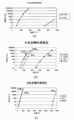
- FIG.1 (a) has shown the vapor pressure of Hf compound
- FIG.1 (b) has shown the vapor pressure of Zr compound
- FIG.1 (c) is Al.
- the vapor pressure of the compound is shown.
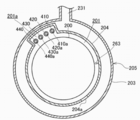
- FIG. 2 is a schematic cross-sectional view along the line AA in FIG. 1.
- FIG. 2 is a block diagram which shows the structure of the controller which the substrate processing apparatus shown in FIG. 1 has.
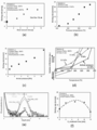
- FIG. 7A is a diagram schematically showing the influence (exhaust time and gas utilization efficiency) on the gas utilization efficiency by the etching gas exhaust system and the exhaust time control (Example 500 ° C., ultimate pressure 500 Pa).
- B is a diagram schematically showing the temperature dependence (temperature and etching rate) of the etching rate
- FIG. 7 (c) is a diagram schematically showing the pressure dependence (total pressure and etching rate) of the etching rate.
- FIG. 7A is a diagram schematically showing the influence (exhaust time and gas utilization efficiency) on the gas utilization efficiency by the etching gas exhaust system and the exhaust time control (Example 500 ° C., ultimate pressure 500 Pa).
- B is a diagram schematically showing the temperature dependence (temperature and etching rate) of the etching rate
- FIG. 7 (c) is a diagram schematically showing the pressure dependence (total pressure and etching rate) of the etching rate.
- FIG. 7 (d) is a diagram schematically showing the influence (temperature and film thickness change amount) on etching and deposition temperature branch point by ultimate pressure control
- FIG. 7 (e) is a view after etching by post-processing
- FIG. 7F is a diagram schematically showing the relationship between the O 3 supply time and the etching rate in the surface oxidation step in the etching process.
- FIG. 1 (a) shows the vapor pressure of fluoride and halide (chloride) of hafnium (Hf)
- FIG. 1 (b) shows the vapor pressure of fluoride and halide of zirconium (Zr)
- FIG. (C) shows the vapor pressure of aluminum (Al) fluoride and halide (chloride, bromide).
- the vapor pressure of halide is higher than that of fluoride, and it is considered that halogen and gas such as chloride and bromide are suitable for etching.
- Table 1 Hf-O as shown in (CRC Handbook of Chemistry and Physics, 84 th, 2004 reference from), Zr-O binding energy of each 8.30EV, large as 8.02EV, Hf, oxidation of Zr Things are difficult to etch materials. In order to proceed with the etching, it is necessary to activate Hf—O, Zr—O, and Al—O bond breakage, form Hf, Zr, and Al chlorides and bromides, and desorb the reaction products. is there.
- the etching of ZrO is considered to be thermal (thermal) etching using a gas containing boron and a halogen-containing gas, for example, chlorine (hereinafter referred to as B—Cl gas).
- B—Cl gas a gas containing boron and a halogen-containing gas, for example, chlorine
- the reaction when the ZrO film is etched with B—Cl gas is considered to proceed as in the following formula (1).
- the thermal decomposition reaction of B—Cl gas is considered as the formula (2).
- Equation (1) When etching with B—Cl gas, as can be seen from equation (1), boron radicals and chlorine radicals generated by decomposition of B—Cl are combined with oxygen and Zr in Zr—O, respectively, and gaseous BOx and ZrCl. Etching proceeds by generating 4 .
- the bond energy of B—O is 8.26 eV, which is larger than the bond energy of Zr—O, and can break the Zr—O bond.
- the bond energy of Zr—Cl is 5.52 eV, which is smaller than the bond energy of Zr—O and is not sufficient to break the bond of Zr—O, but the Gibbs free energy of chemical reaction rate and chemical equilibrium and From Le Chatelier's law, the reaction shown in Formula (1) can proceed in the positive direction within a certain range of conditions. It is also conceivable that the binding energy varies depending on the film quality (difference in Zr—O interatomic distance and crystal structure) depending on the method of forming the ZrO film.
- the sample used for the evaluation of the present invention was prepared by a method of alternately supplying a plurality of processing gases as described later. It is considered that some films produced by this method have a Zr—O bond energy smaller than the value shown in Table 1. Therefore, it is considered that the ZrO film can be etched by using B—Cl gas as an etching gas as will be described later.
- the present inventors paid attention to a substrate processing method after etching. For example, consider a case where carbon (C) derived from a Zr-containing raw material remains in the ZrO film and ZrClx in which Cl derived from an etching gas is bonded to Zr is deposited on the surface. At this time, it is conceivable that carbon is desorbed as COx and ZrClx is reoxidized to ZrO by treating the film surface with an oxygen-containing gas such as ozone (O 3 ).
- the characteristics of the surface are the presence of defects after COx desorption and the weak bond equilibrium state of Zr—O and Zr—Zr, which is considered to be a surface equilibrium state suitable for etching.
- chlorine gas or etching gas can be used.
- bromine-based gas especially chlorine-based gas
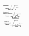
- Introducing the method using the superheated vapor pressure of the cleaning gas (paper doro method) to slow down the total pressure rise and increase the cleaning gas partial pressure Ii) A process of performing a containment introduction type considering the delay of the reaction when introducing the etching gas, and (iii) A process of performing a slow exhaust type considering the delay of the reaction when exhausting the etching gas.
- the substrate processing apparatus 10 is configured as an example of an apparatus used in a semiconductor device manufacturing process.
- the substrate processing apparatus 10 includes a processing furnace 202 provided with a heater 207 as a heating means (heating mechanism, heating system).
- the heater 207 has a cylindrical shape and is vertically installed by being supported by a heater base (not shown) as a holding plate.
- An outer tube 203 that constitutes a reaction vessel (processing vessel) concentrically with the heater 207 is disposed inside the heater 207.
- the outer tube 203 is made of a heat-resistant material such as quartz (SiO 2 ) or silicon carbide (SiC), and is formed in a cylindrical shape with the upper end closed and the lower end opened.
- a manifold (inlet flange) 209 is disposed below the outer tube 203 concentrically with the outer tube 203.
- the manifold 209 is made of a metal such as stainless steel (SUS), for example, and is formed in a cylindrical shape with an upper end and a lower end opened.
- An O-ring 220a as a seal member is provided between the upper end portion of the manifold 209 and the outer tube 203. As the manifold 209 is supported by the heater base, the outer tube 203 is installed vertically.
- An inner tube 204 that constitutes a reaction vessel is disposed inside the outer tube 203.
- the inner tube 204 is made of a heat resistant material such as quartz (SiO 2 ) or silicon carbide (SiC), and is formed in a cylindrical shape with the upper end closed and the lower end opened.
- a processing vessel (reaction vessel) is mainly constituted by the outer tube 203, the inner tube 204, and the manifold 209.
- a processing chamber 201 is formed in a cylindrical hollow portion of the processing container (inside the inner tube 204).
- the processing chamber 201 is configured to be able to accommodate wafers 200 as substrates in a state where they are arranged in multiple stages in a vertical posture in a horizontal posture by a boat 217 described later.
- nozzles 410, 420, 430, and 440 are provided so as to penetrate the side wall of the manifold 209 and the inner tube 204.
- Gas supply pipes 310, 320, 330, and 340 are connected to the nozzles 410, 420, 430, and 440, respectively.
- the processing furnace 202 of this embodiment is not limited to the above-mentioned form. The number of nozzles and the like is appropriately changed as necessary.
- the gas supply pipes 310, 320, 330, and 340 are provided with mass flow controllers (MFCs) 312, 322, 332, and 342, which are flow controllers (flow controllers) in order from the upstream side.
- MFCs mass flow controllers
- the gas supply pipes 310, 320, 330, and 340 are provided with valves 314, 324, 334, and 344, which are on-off valves, respectively.
- Gas supply pipes 510, 520, 530, and 540 for supplying an inert gas are connected to the downstream sides of the valves 314, 324, 334, and 344 of the gas supply pipes 310, 320, 330, and 340, respectively.
- MFCs 512, 522, 532, and 542 that are flow rate controllers (flow rate control units) and valves 514, 524, 534, and 544 that are on-off valves are sequentially provided from the upstream side. Is provided.
- the nozzles 410, 420, 430, and 440 are configured as L-shaped nozzles, and the horizontal portion thereof is provided so as to penetrate the side wall of the manifold 209 and the inner tube 204.
- the vertical portions of the nozzles 410, 420, 430, and 440 are disposed inside a channel-shaped (groove-shaped) preliminary chamber 201 a that protrudes radially outward of the inner tube 204 and extends in the vertical direction. It is provided in the preliminary chamber 201a along the inner wall of the inner tube 204 (upward in the arrangement direction of the wafers 200).
- the nozzles 410, 420, 430, and 440 are provided so as to extend from the lower region of the processing chamber 201 to the upper region of the processing chamber 201, and a plurality of gas supply holes 410 a and 420 a are respectively provided at positions facing the wafer 200. , 430a, 440a. Accordingly, the processing gas is supplied to the wafer 200 from the gas supply holes 410a, 420a, 430a, and 440a of the nozzles 410, 420, 430, and 440, respectively.
- a plurality of gas supply holes 410a, 420a, 430a, 440a are provided from the lower part to the upper part of the inner tube 204, have the same opening area, and are provided at the same opening pitch.
- the gas supply holes 410a, 420a, 430a, and 440a are not limited to the above-described form.
- the opening area may be gradually increased from the lower part of the inner tube 204 toward the upper part. Thereby, the flow rate of the gas supplied from the gas supply holes 410a, 420a, 430a, 440a can be made more uniform.
- a plurality of gas supply holes 410 a, 420 a, 430 a, 440 a of the nozzles 410, 420, 430, 440 are provided at positions from the bottom to the top of the boat 217 described later. Therefore, the processing gas supplied into the processing chamber 201 from the gas supply holes 410 a, 420 a, 430 a, and 440 a of the nozzles 410, 420, and 430 is supplied to the wafers 200, that is, the boat 217 stored from the bottom to the top of the boat 217. It is supplied to the entire area of the accommodated wafer 200.
- the nozzles 410, 420, 430, and 440 may be provided so as to extend from the lower region to the upper region of the processing chamber 201, but may be provided so as to extend to the vicinity of the ceiling of the boat 217. preferable.
- a metal-containing gas (metal-containing raw material) is supplied as a processing gas into the processing chamber 201 through the MFC 312, the valve 314, and the nozzle 410.
- a metal-containing gas for example, tetrakisethylmethylaminozirconium (TEMAZ, Zr [N (CH 3 ) C 2 H 5 ] 4 ) containing zirconium (Zr) can be used.
- TEMAZ is a liquid at normal temperature and pressure, and is used as a TEMAZ gas that is vaporized by a vaporizer (not shown) and is a vaporized gas.
- a first oxygen-containing gas (oxygen-containing gas, O-containing gas) is supplied from the gas supply pipe 320 into the processing chamber 201 through the MFC 322, the valve 324, and the nozzle 420 as an oxidizing gas.
- oxygen-containing gas oxygen-containing gas, O-containing gas
- O-containing gas oxygen-containing gas
- ozone (O 3 ) or the like is used as the first oxygen-containing gas.
- An etching gas (cleaning gas) is supplied from the gas supply pipe 330 into the processing chamber 201 through the MFC 332, the valve 334, and the nozzle 430 as a processing gas.
- a boron trichloride (BCl 3 ) gas that is a halide and contains chlorine (Cl) is used.
- a reformed gas as a reducing gas is supplied as a processing gas into the processing chamber 201 through the MFC 342, the valve 344, and the nozzle 440.
- a reformed gas for example, water vapor (H 2 O) which is a second oxygen-containing gas and also a hydrogen-containing gas is used.
- the gas supply pipes 310, 320, 330, and 340, MFCs 312, 322, 332, and 342, valves 314, 324, 334, and 344, and nozzles 410, 420, 430, and 440 constitute a processing gas supply system. Only the nozzles 410, 420, 430, and 440 may be considered as the processing gas supply system.
- the processing gas supply system may be simply referred to as a gas supply system.
- the metal-containing gas supply system When flowing a metal-containing gas from the gas supply pipe 310, the metal-containing gas supply system is mainly configured by the gas supply pipe 310, the MFC 312 and the valve 314, but the nozzle 410 may be included in the metal-containing gas supply system. Good.
- the gas supply pipe 320, the MFC 322, and the valve 324 When flowing the first oxygen-containing gas from the gas supply pipe 320, the gas supply pipe 320, the MFC 322, and the valve 324 mainly constitute the first oxygen-containing gas supply system, but the nozzle 420 is connected to the first oxygen-containing gas. It may be included in the gas supply system.
- the first oxygen-containing gas supply system is also referred to as an O 3 gas supply system.
- the chlorine-based gas supply system is mainly configured by the gas supply pipe 330, the MFC 332, and the valve 334, but the nozzle 430 may be included in the chlorine-based gas supply system. Good.
- the chlorine-based gas supply system is also referred to as a BCl 3 gas supply system.
- the nozzle 440 When flowing the second oxygen-containing gas from the gas supply pipe 340, the gas supply pipe 340, the MFC 342, and the valve 344 mainly constitute a reducing gas supply system, but the nozzle 440 may be referred to as a reducing gas supply system. .
- the reducing gas supply system is also referred to as a second oxygen-containing gas supply system.
- the second oxygen-containing gas supply system is also referred to as an H 2 O gas supply system.
- an inert gas supply system is mainly configured by the gas supply pipes 510, 520, and 530, the MFCs 512, 522, and 532, and the valves 514, 524, and 534.
- the inert gas supply system can also be referred to as a purge gas supply system, a dilution gas supply system, or a carrier gas supply system.
- the gas supply method is performed in an annular vertically long space defined by the inner wall of the inner tube 204 and the ends of the plurality of wafers 200, that is, in the spare chamber 201a in a cylindrical space.
- Gas is conveyed via nozzles 410, 420, 430, and 440 arranged in the above. Then, gas is ejected into the inner tube 204 from a plurality of gas supply holes 410a, 420a, 430a, 440a provided at positions facing the wafers of the nozzles 410, 420, 430, 440.
- the exhaust hole (exhaust port) 204a is a through hole formed at a position opposite to the nozzles 410, 420, 430, and 440 on the side wall of the inner tube 204, that is, a position 180 degrees opposite to the spare chamber 201a.
- it is a slit-like through hole that is elongated in the vertical direction.
- the gas that is supplied into the processing chamber 201 from the gas supply holes 410a, 420a, 430a, and 440a of the nozzles 410, 420, 430, and 440 and flows on the surface of the wafer 200, that is, the residual gas (residual gas) is Then, the gas flows into an exhaust path 206 formed by a gap formed between the inner tube 204 and the outer tube 203 through the exhaust hole 204a.
- the gas flowing into the exhaust path 206 flows into the exhaust pipe 231 and is discharged out of the processing furnace 202.
- the exhaust hole 204a is provided at a position facing the plurality of wafers 200 (preferably a position facing from the upper part to the lower part of the boat 217), and from the gas supply holes 410a, 420a, 430a, 440a to the wafer in the processing chamber 201.
- the gas supplied in the vicinity of 200 flows in the horizontal direction, that is, in the direction parallel to the surface of the wafer 200, and then flows into the exhaust path 206 through the exhaust holes 204a. That is, the gas remaining in the processing chamber 201 is exhausted in parallel to the main surface of the wafer 200 through the exhaust hole 204a.
- the exhaust hole 204a is not limited to being configured as a slit-like through hole, and may be configured by a plurality of holes.
- the manifold 209 is provided with an exhaust pipe 231 for exhausting the atmosphere in the processing chamber 201.
- the exhaust pipe 231 includes, in order from the upstream side, a pressure sensor 245 serving as a pressure detector (pressure detector) that detects the pressure in the processing chamber 201, an APC (Auto Pressure Controller) valve 231 a, and a vacuum pump serving as a vacuum exhaust device. 246 is connected.
- the APC valve 231a can open and close the vacuum pump 246 while operating the vacuum pump 246, and can stop the vacuum exhaust and vacuum exhaust in the processing chamber 201. Further, the APC valve 231a can be operated while the vacuum pump 246 is operated. By adjusting the opening, the pressure in the processing chamber 201 can be adjusted.
- An exhaust system that is, an exhaust line, is mainly configured by the exhaust hole 204a, the exhaust path 206, the exhaust pipe 231, the APC valve 231a, and the pressure sensor 245. Note that the vacuum pump 246 may be included in the exhaust system.
- a seal cap 219 is provided as a furnace opening lid capable of airtightly closing the lower end opening of the manifold 209.
- the seal cap 219 is configured to contact the lower end of the manifold 209 from the lower side in the vertical direction.
- the seal cap 219 is made of a metal such as SUS and is formed in a disk shape.
- an O-ring 220b is provided as a seal member that comes into contact with the lower end of the manifold 209.
- a rotation mechanism 267 that rotates the boat 217 that accommodates the wafers 200 is installed on the seal cap 219 on the opposite side of the processing chamber 201.
- a rotation shaft 255 of the rotation mechanism 267 passes through the seal cap 219 and is connected to the boat 217.
- the rotation mechanism 267 is configured to rotate the wafer 200 by rotating the boat 217.
- the seal cap 219 is configured to be lifted and lowered in the vertical direction by a boat elevator 115 as a lifting mechanism vertically installed outside the outer tube 203.
- the boat elevator 115 is configured so that the boat 217 can be carried in and out of the processing chamber 201 by moving the seal cap 219 up and down.
- the boat elevator 115 is configured as a transfer device (transfer mechanism) that transfers the boat 217 and the wafers 200 accommodated in the boat 217 into and out of the processing chamber 201.
- the boat 217 as the substrate support is configured to support a plurality of, for example, 25 to 200 wafers 200 in a horizontal posture and in a multi-stage by aligning them in the vertical direction with their centers aligned. It is configured to arrange at intervals.
- the boat 217 is made of a heat-resistant material such as quartz or SiC.
- a heat insulating plate 218 made of a heat resistant material such as quartz or SiC is supported in multiple stages (not shown) in a horizontal posture. With this configuration, heat from the heater 207 is not easily transmitted to the seal cap 219 side.
- this embodiment is not limited to the above-mentioned form.
- a heat insulating cylinder configured as a cylindrical member made of a heat resistant material such as quartz or SiC may be provided.
- a temperature sensor 263 as a temperature detector is installed in the inner tube 204, and the temperature in the processing chamber 201 is adjusted by adjusting the energization amount to the heater 207 based on the temperature information detected by the temperature sensor 263. It is configured to have a desired temperature distribution.
- the temperature sensor 263 is configured in an L shape similarly to the nozzles 410, 420, 430, and 440, and is provided along the inner wall of the inner tube 204.
- the controller 280 as a control unit (control means) is configured as a computer including a CPU (Central Processing Unit) 280a, a RAM (Random Access Memory) 280b, a storage device 280c, and an I / O port 280d.
- the RAM 280b, the storage device 280c, and the I / O port 280d are configured to exchange data with the CPU 280a via an internal bus.
- an input / output device 282 configured as a touch panel or the like is connected to the controller 280.
- the storage device 280c includes, for example, a flash memory, a HDD (Hard Disk Drive), and the like.
- a control program that controls the operation of the substrate processing apparatus, a process recipe that describes the procedure and conditions of a semiconductor device manufacturing method described later, and the like are stored in a readable manner.
- the process recipe is a combination of processes so that a predetermined result can be obtained by causing the controller 280 to execute each step (each step) in the semiconductor device manufacturing method described later, and functions as a program.
- the process recipe, the control program, and the like are collectively referred to simply as a program.
- the RAM 280b is configured as a memory area (work area) in which a program or data read by the CPU 280a is temporarily stored.
- the I / O port 280d includes the above-described MFC 312, 322, 332, 342, 512, 522, 532, 542, valve 314, 324, 334, 344, 514, 524, 534, 544, pressure sensor 245, APC valve 231a, The vacuum pump 246, the heater 207, the temperature sensor 263, the rotation mechanism 267, the boat elevator 115, etc. are connected.
- the CPU 280a is configured to read and execute a control program from the storage device 280c, and to read a recipe or the like from the storage device 280c in response to an operation command input from the input / output device 282 or the like.
- the CPU 280a adjusts the flow rates of various gases by the MFCs 312, 322, 332, 342, 512, 522, 532, 542, valves 314, 324, 334, 344, 514, 524, and 534 in accordance with the contents of the read recipe.
- the controller 280 is stored in an external storage device 283 (for example, a magnetic disk, a magnetic disk such as a flexible disk or a hard disk, an optical disk such as a CD or DVD, a magneto-optical disk such as an MO, or a semiconductor memory such as a USB memory or a memory card).
- the above-mentioned program can be configured by installing it in a computer.
- the storage device 280c and the external storage device 283 are configured as computer-readable recording media. Hereinafter, these are collectively referred to simply as a recording medium.
- the recording medium may include only the storage device 280c alone, the external storage device 283 alone, or both.
- the provision of the program to the computer may be performed using communication means such as the Internet or a dedicated line without using the external storage device 283.
- Substrate processing step As a step of manufacturing a semiconductor device (device), a film forming step of supplying a metal-containing gas and a first oxygen-containing gas to the substrate to form a metal oxide film is performed. An example of performing an etching process will be described. The film forming process and the etching process are performed using the processing furnace 202 of the substrate processing apparatus 10 described above. In the following description, the operation of each part constituting the substrate processing apparatus 10 is controlled by the controller 280.
- wafer when the term “wafer” is used, it means “wafer itself” or “a laminate (aggregate) of a wafer and a predetermined layer or film formed on the surface thereof”. "(That is, a wafer including a predetermined layer or film formed on the surface).
- wafer surface when the term “wafer surface” is used in this specification, it means “the surface of the wafer itself (exposed surface)” or “the surface of a predetermined layer or film formed on the wafer”. That is, it may mean “the outermost surface of the wafer as a laminated body”.
- substrate is also synonymous with the term “wafer”.
- a plurality of wafers 200 are loaded into the processing chamber 201 (boat loading). Specifically, when a plurality of wafers 200 are loaded into the boat 217 (wafer charge), the boat 217 supporting the plurality of wafers 200 is lifted by the boat elevator 115 as shown in FIG. And is carried into the processing chamber 201. In this state, the seal cap 219 closes the lower end opening of the reaction tube 203 via the O-ring 220.
- the processing chamber 201 is evacuated by a vacuum pump 246 so that a desired pressure (degree of vacuum) is obtained. At this time, the pressure in the processing chamber 201 is measured by the pressure sensor 245, and the APC valve 231a is feedback-controlled based on the measured pressure information (pressure adjustment). The vacuum pump 246 keeps operating at least until the processing on the wafer 200 is completed. Further, the processing chamber 201 is heated by the heater 207 so as to have a desired temperature. At this time, the energization amount to the heater 207 is feedback-controlled based on the temperature information detected by the temperature sensor 263 so that the processing chamber 201 has a desired temperature distribution (temperature adjustment). The heating of the processing chamber 201 by the heater 207 is continuously performed at least until the processing on the wafer 200 is completed.
- a step of forming a ZrO film, which is a high dielectric constant oxide film, as a metal oxide film on the wafer 200 is executed.
- TEMAZ gas supply step The valve 314 is opened and TEMAZ gas is caused to flow in the gas supply pipe 310.
- the flow rate of the TEMAZ gas is adjusted by the MFC 312, supplied from the gas supply hole 410 of the nozzle 410 into the processing chamber 201, and exhausted from the exhaust pipe 231.
- the TEMAZ gas is supplied to the wafer 200.
- the valve 514 is opened and N 2 gas is allowed to flow into the gas supply pipe 510.
- the flow rate of the N 2 gas flowing through the gas supply pipe 510 is adjusted by the MFC 512.
- the N 2 gas is supplied into the processing chamber 201 together with the TEMAZ gas, and is exhausted from the exhaust pipe 231.
- the valves 524, 534, and 544 are opened, and N 2 gas is allowed to flow into the gas supply pipes 520, 530, and 540.
- the N 2 gas is supplied into the processing chamber 201 through the gas supply pipes 320, 330, and 340 and the nozzles 420, 430, and 440 and is exhausted from the exhaust pipe 231.
- the APC valve 231a is appropriately adjusted so that the pressure in the processing chamber 201 is, for example, a pressure in the range of 20 to 500 Pa.
- 20 to 500 Pa represents 20 Pa or more and 500 Pa or less.
- the supply flow rate of the TEMAZ gas controlled by the MFC 312 is, for example, a flow rate in the range of 0.1 to 3.0 g / min.
- the time for exposing the wafer 200 to TEMAZ, that is, the gas supply time (irradiation time) is, for example, a time within a range of 10 to 300 seconds.
- the temperature of the heater unit 207 is set to such a temperature that the temperature of the wafer 200 becomes a temperature within a range of 150 to 300 ° C., for example.
- a Zr-containing layer is formed on the wafer 200 by supplying the TEMAZ gas.
- organic substances carbon (C), hydrogen (H), nitrogen (N), etc.
- TEMAZ gas slightly remain as residual elements.
- the valve 314 After supplying the TEMAZ gas for a predetermined time, the valve 314 is closed to stop the supply of the TEMAZ gas. At this time, the APC valve 231a of the exhaust pipe 231 is kept open, the inside of the processing chamber 201 is evacuated by the vacuum pump 246, and the TEMAZ gas remaining in the processing chamber 201 and contributing to the reduction is removed. Eliminate from within 201. At this time, the valves 524, 534, and 544 are kept open, and the supply of N 2 gas into the processing chamber 201 is maintained. The N 2 gas acts as a purge gas, and can enhance the effect of removing the TEMAZ gas remaining in the processing chamber 201 or contributing to the reduction from the processing chamber 201.
- O 3 gas supply step The valve 324 is opened, and O 3 gas that is the first oxygen-containing gas is caused to flow into the gas supply pipe 320.
- the flow rate of the O 3 gas is adjusted by the MFC 322, supplied from the gas supply hole 420 a of the nozzle 420 into the processing chamber 201, and exhausted from the exhaust pipe 231.
- O 3 gas is supplied to the wafer 200.
- the valve 524 is opened, and an inert gas such as N 2 gas is allowed to flow into the gas supply pipe 520.
- the flow rate of the N 2 gas flowing through the gas supply pipe 520 is adjusted by the MFC 522, supplied into the processing chamber 201 together with the O 3 gas, and exhausted from the exhaust pipe 231.
- the valves 514, 534, and 544 are opened, and N 2 gas is allowed to flow into the gas supply pipes 510, 530, and 540.
- the N 2 gas is supplied into the processing chamber 201 through the gas supply pipes 310, 330, and 340 and the nozzles 410, 430, and 440 and is exhausted from the exhaust pipe 231.
- the APC valve 231a When flowing the O 3 gas, the APC valve 231a is appropriately adjusted so that the pressure in the processing chamber 201 is, for example, in the range of 50 to 500 Pa.
- the supply flow rate of the O 3 gas controlled by the MFCs 235b and 235c is, for example, a flow rate in the range of 5 to 30 slm.
- the time for exposing the wafer 200 to the O 3 gas that is, the gas supply time (irradiation time) is, for example, a time within a range of 10 to 300 seconds.
- the temperature of the heater unit 207 at this time is the same as that in step S101.
- a cycle in which the above steps are sequentially performed is performed one or more times (a predetermined number of times (n times) to form a ZrO film having a predetermined thickness on the wafer 200.
- the above cycle is preferably repeated a plurality of times.
- the TEMAZ gas and the O 3 gas are alternately supplied to the wafer 200 so as not to be mixed with each other (time division).
- N 2 gas is supplied into the processing chamber 201 from each of the gas supply pipes 510, 520, 530, and 540 and exhausted from the exhaust pipe 231.
- the N 2 gas acts as a purge gas, whereby the inside of the processing chamber 201 is purged with an inert gas, and the gas and by-products remaining in the processing chamber 201 are removed from the inside of the processing chamber 201 (after purge). Thereafter, the atmosphere in the processing chamber 201 is replaced with an inert gas (inert gas replacement), and the pressure in the processing chamber 201 is returned to normal pressure (return to atmospheric pressure).
- the boat 217 is loaded into the processing chamber 201 (boat loading) without loading the wafer 200.
- the boat 217 is lifted by the boat elevator 115 and is carried into the processing chamber 201.
- the seal cap 219 closes the lower end opening of the reaction tube 203 via the O-ring 220.
- the processing chamber 201 is evacuated by a vacuum pump 246 so that a desired pressure (degree of vacuum) is obtained. At this time, the pressure in the processing chamber 201 is measured by the pressure sensor 245, and the APC valve 231a is feedback-controlled based on the measured pressure information (pressure adjustment). The vacuum pump 246 keeps operating at least until the processing on the wafer 200 is completed. Further, the processing chamber 201 is heated by the heater 207 so as to have a desired temperature. At this time, the energization amount to the heater 207 is feedback-controlled based on the temperature information detected by the temperature sensor 263 so that the processing chamber 201 has a desired temperature distribution (temperature adjustment). Heating of the processing chamber 201 by the heater 207 is continuously performed at least until the etching process is completed.
- the valve 334 is opened, and BCl 3 gas is caused to flow into the gas supply pipe 330 at a first BCl 3 gas supply flow rate (also referred to as a first flow rate).
- the flow rate of the BCl 3 gas is adjusted by the MFC 332, supplied from the gas supply hole 430 a of the nozzle 430 into the processing chamber 201, and exhausted from the exhaust pipe 231.
- BCl 3 gas is supplied to the wafer 200.
- the valve 534 is opened, and an inert gas such as N 2 gas is allowed to flow into the gas supply pipe 530.
- the flow rate of the N 2 gas flowing through the gas supply pipe 530 is adjusted by the MFC 532, supplied into the processing chamber 201 together with the BCl 3 gas, and exhausted from the exhaust pipe 231.
- the valves 514, 524, and 544 are opened, and N 2 gas is allowed to flow into the gas supply pipes 510, 520, and 540.
- the N 2 gas is supplied into the processing chamber 201 through the gas supply pipes 310, 320, 340 and the nozzles 410, 420, 440 and is exhausted from the exhaust pipe 231.
- a reaction in which boron radicals are adsorbed and desorbed as BHx can be considered. Thereafter, chlorine radicals and boron radical BCl 3 gas is generated continues to decomposition combined with Zr and O of ZrO surface respectively, resulting ZrClx, BOx, a Cl 2 or the like, that they are removed from the process chamber 201 Etching proceeds.
- the reaction product of the ZrO film and the BCl 3 gas is generated through the following two steps. That is, the Zr—O bond is cleaved by B—Cl, and a Zr—Cl bond and BOx are generated. Further, the Zr—O bond in which the chlorine radical remains is broken to generate BOx and ZrCl 4 . Thus, it is considered that there is a reaction delay time in the reaction between the ZrO film and the BCl 3 gas.
- the controller 280 controls the heater 207 to heat the inside of the processing chamber 201 to a predetermined temperature within a range of, for example, 200 to 800 ° C., preferably 400 to 550 ° C. to activate the BCl 3 gas.
- a plasma generator may be installed inside or outside the processing chamber 201 so that BCl 3 gas is subjected to plasma processing, and chlorine radicals are generated in the processing chamber 201 or supplied to the processing chamber 201.
- the APC valve 231a is closed or substantially closed so as not to affect the processing, and the BCl 3 gas is contained in the processing chamber 201. By confining the BCl 3 gas, the influence on the etching due to the reaction delay described above can be reduced.
- the pressure in the processing chamber 201 is a first pressure, for example, 1 to 13300 Pa, preferably 6650 to 13300 Pa, more preferably 1000 to 13300 Pa.
- the supply flow rate of the BCl 3 gas controlled by the MFC 332 is, for example, 0.1 to 10 slm, and preferably 3 to 5 slm.
- the time for supplying the BCl 3 gas to the processing chamber 201 (BCl 3 gas supply time) is, for example, a time within the range of 60 to 600 seconds.
- the valve 324 is opened, and O 3 gas is allowed to flow into the gas supply pipe 320.
- the flow rate of the O 3 gas is adjusted by the MFC 322, supplied from the gas supply hole 420 a of the nozzle 420 into the processing chamber 201, and exhausted from the exhaust pipe 231.
- O 3 gas is supplied to the wafer 200.
- the valve 524 is opened, and an inert gas such as N 2 gas is allowed to flow into the gas supply pipe 520.
- the flow rate of the N 2 gas flowing through the gas supply pipe 520 is adjusted by the MFC 522, supplied into the processing chamber 201 together with the O 3 gas, and exhausted from the exhaust pipe 231.
- the valves 514, 534, and 544 are opened, and N 2 gas is allowed to flow into the gas supply pipes 510, 530, and 540.
- the N 2 gas is supplied into the processing chamber 201 through the gas supply pipes 310, 330, and 340 and the nozzles 410, 430, and 440 and is exhausted from the exhaust pipe 231.
- the APC valve 231a is adjusted appropriately so that the pressure in the processing chamber 201 is, for example, in the range of 50 to 1330 Pa.
- the supply flow rate of the O 3 gas controlled by the MFCs 235b and 235c is set, for example, within a range of 5 to 40 slm.
- the time for exposing the wafer 200 to the O 3 gas, that is, the gas supply time (irradiation time) is, for example, a time within a range of 10 to 600 seconds.
- the temperature of the heater unit 207 at this time is the same as that in step S101.
- the inner wall of the processing chamber 201, the surface of the boat 217, and the like are oxidized (treated). Also, the by-product generated in the high pressure etching step is reoxidized. For example, the Zr—Cl bond of ZrClx is cleaved and removed as Cl 2 and reoxidized to ZrO. Further, organic substances remaining in the ZrO film react with the O 3 gas and are removed from the processing chamber 201. For example, carbon (C) remaining in the ZrO film reacts with O 3 gas to become COx, and is removed from the processing chamber 201. At this time, the outermost surface of the film has a carbon defect after COx is desorbed, and a weak bond equilibrium state of Zr—O and Zr—Zr. This state is considered to be a surface equilibrium state suitable for etching.
- the flow rate of the N 2 gas flowing through the gas supply pipe 530 is adjusted by the MFC 532, supplied into the processing chamber 201 together with the BCl 3 gas, and exhausted from the exhaust pipe 231.
- the valves 514, 524, and 544 are opened, and N 2 gas is allowed to flow into the gas supply pipes 510, 520, and 540.
- the N 2 gas is supplied into the processing chamber 201 through the gas supply pipes 310, 320, 340 and the nozzles 410, 420, 440 and is exhausted from the exhaust pipe 231.
- the ZrO film attached to the inside of the processing chamber 201 (the inner wall of the processing chamber 201, the boat 217, etc.) by the supply of BCl 3 gas reacts with the ZrO film that was not removed in the high-pressure etching step, and ZrClx, BOx, etc. Then, it is removed from the processing chamber 201. Further, the supply of BCl 3 gas in the high-pressure etching step reacts with Cl (residual chlorine) remaining in the ZrO film, and Cl is removed from the processing chamber 201.
- the controller 280 controls the heater 207 to heat the inside of the processing chamber 201 to the same temperature as the high-pressure etching step.
- a plasma generator is installed inside or outside the processing chamber 201 to plasma-process BCl 3 gas, and chlorine radicals are generated in the processing chamber 201 or supplied to the processing chamber 201. It is good also as a simple structure.
- the APC valve 231a is closed or substantially closed so as not to affect the processing, and the BCl 3 gas is contained in the processing chamber 201. Then, the pressure in the processing chamber 201 is set to a second pressure that is lower than the first pressure in the high-pressure etching step.
- the pressure is maintained at a predetermined pressure in the range of 1 to 10,000 Pa, preferably 5000 to 8000 Pa, more preferably 5000 to 6650 Pa.
- the supply flow rate of the BCl 3 gas controlled by the MFC 332 is, for example, 0.1 to 10 slm, and preferably 3 to 5 slm.
- the time for supplying the BCl 3 gas to the processing chamber 201 (BCl 3 gas supply time) is, for example, a time within a range of 30 to 300 seconds.
- the ZrO film adhering to the inside of the processing chamber 201 is removed by performing a cycle of sequentially performing the above steps one or more times (a predetermined number of times (m times).
- the above cycle is preferably repeated a plurality of times.
- FIG. 7 (b) shows the influence of the temperature control on the etching rate.
- the etching reaction tends to increase exponentially with a temperature rise in the temperature range of 400 ° C. or higher.
- the temperature is 550 ° C. or higher, the increasing rate of the etching rate is slow. This is presumably because the thermal decomposition reaction of the reaction gas occurs preferentially under high temperature conditions, and the density of chlorine radicals and the like formed during the etching reaction is reduced.
- FIG. 7 (d) shows the influence on the etching and deposition temperature branch point by the ultimate pressure control. While the ultimate pressure increases, the etching efficiency is also improved, but the etching and deposition temperature branch point also shifts to the high temperature side.
- the reason is considered to be related to the vapor pressure curve of Zr chloride shown in FIG. That is, there is a trade-off relationship between the improvement of the etching rate by increasing pressure and the etching and deposition temperature branch point.
- the paper vapor type that is, the heating vapor pressure of the chlorine-based gas is reduced. Install using.
- the reaction chamber is introduced by containment. Fully close the exhaust system.
- the paper doro type is more suitable for the industry than the bubbling type because it is considered to have a simpler structure and better vapor pressure stability.
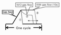
- FIG. (I) As the ultimate pressure (for example, 500 Pa), when exhausting quickly after the pressure reaches 500 Pa, (ii) When exhausting while supplying chlorine-based gas for 10 seconds and controlling the pressure to 500 Pa (Gas flow 10s), (iii) Three patterns in the case of slowly evacuating (slow exhaust, with time control) by stopping the supply of chlorine-based gas.
- FIG. 7A shows the results of three patterns when the inside of the processing chamber 201 is heated to 500 ° C.
- FIG. 7F in the surface oxidation step, the etching rate changes depending on the O 3 treatment time (O 3 supply time).
- FIG. 7 (f) shows that the etching rate decreases when O 3 gas is allowed to flow for 2 minutes or less or 8 minutes or more under the conditions of FIG. 7 (f).
- H 2 O is introduced into the processing chamber 201 to remove residual chlorine.
- the valve 344 is opened and H 2 O is caused to flow in the gas supply pipe 340.
- the flow rate of H 2 O is adjusted by the MFC 342, supplied to the processing chamber 201 from the gas supply hole 440 a of the nozzle 440, and exhausted from the exhaust pipe 231. At this time, H 2 O is supplied to the wafer 200.
- the valve 544 is opened, and an inert gas such as N 2 gas is allowed to flow into the gas supply pipe 540.
- the flow rate of the N 2 gas flowing through the gas supply pipe 540 is adjusted by the MFC 542, supplied into the processing chamber 201 together with H 2 O, and exhausted from the exhaust pipe 231.
- the valves 514, 524, 534 are opened, and N 2 gas is allowed to flow into the gas supply pipes 510, 520, 530.
- the N 2 gas is supplied into the processing chamber 201 through the gas supply pipes 310, 320, 330 and the nozzles 410, 420, 430 and is exhausted from the exhaust pipe 231.
- H 2 O chlorine remaining in the processing chamber 201 is removed.
- N 2 gas is supplied into the processing chamber 201 from each of the gas supply pipes 510, 520, 530, and 540 and exhausted from the exhaust pipe 231.
- the N 2 gas acts as a purge gas, whereby the inside of the processing chamber 201 is purged with an inert gas, and the gas and by-products remaining in the processing chamber 201 are removed from the inside of the processing chamber 201 (after purge). Thereafter, the atmosphere in the processing chamber 201 is replaced with an inert gas (inert gas replacement), and the pressure in the processing chamber 201 is returned to normal pressure (return to atmospheric pressure).
- a film forming process is performed after the inside of the processing chamber 201 is cleaned (the attached ZrO film is etched). After the film forming process is performed a predetermined number of times, the etching process is performed again as maintenance.
- the ZrO film is exemplified as the high dielectric constant oxide film to be etched.
- the present invention is not limited to this, and the oxide is lower than the binding energy of ZrO or higher than the vapor pressure of Zr chloride. (Including mixed oxides).
- ZrOy, HfOy, AlxOy, HfSixOy, HfAlxOy, ZrSiOy, ZrAlOy, TixOy, TaxOy (x and y are integers or decimals greater than 0) are used as the high dielectric constant oxide.
- the present invention can also be applied to a zirconium oxide film, a hafnium oxide film, an aluminum oxide film, a titanium oxide film, a tantalum oxide film, and a composite film thereof.
- TEMAZ is illustrated as an organic type raw material, not only this but another raw material is applicable if it is an organic compound.
- an organic Hf raw material such as tetrakisethylmethylaminohafnium (Hf [N (CH 3 ) CH 2 CH 3 ] 4 , TEMAH), an organic Al raw material such as trimethylaluminum ((CH 3 ) 3 Al, TMA), Organic Si raw materials such as trisdimethylaminosilane (SiH (N (CH 3 ) 2 ) 3 , TDMAS), organic Ti raw materials such as tetrakisdimethylamino titanium (Ti [N (CH 3 ) 2 ] 4 , TDMAT), penta Organic Ta raw materials such as kissdimethylamino tantalum (Ta (N (CH 3 ) 2 ) 5 , PDMAT) can also be applied.
- Hf raw material such as tetrakisethylmethylaminohafnium (Hf [
- O 3 gas is used in the film forming process.
- the present invention is not limited to this, and other raw materials can be used as long as the gas contains oxygen.
- O 2 , O 2 plasma, H 2 O, H 2 O 2 , N 2 O, and the like are also applicable.
- O 3 is exemplified as the oxidizing gas used in the surface oxidation step.
- gases can be applied as long as they are oxygen-containing gases.
- O 2 , O 2 plasma, H 2 O, H 2 O 2 , N 2 O, and the like are also applicable.
- the reformed gas used in the post-processing step H 2 O
- H 2 O the reformed gas used in the post-processing step
- other gases may be used as long as the gas contains an element that reacts with the halogen element contained in the etching gas.
- H 2 O 2 , H 2 , NH 3 and the like are also applicable.
- O 3 is exemplified as the oxidizing gas used in the surface oxidation step
- H 2 O is exemplified as the reformed gas used in the post-processing step.
- the same gas may be used in both steps.
- H 2 O, H 2 O 2 or the like can be used in both steps.
- Process recipes programs describing processing procedures, processing conditions, etc. used to form these various thin films include the contents of substrate processing, cleaning processing, etc. (film type, composition ratio, film quality, film thickness, According to the processing procedure, processing conditions, etc.), it is preferable to prepare each separately (preparing a plurality). And, when starting substrate processing, cleaning processing, etc., an appropriate process recipe, cleaning recipe, etc. is appropriately selected from a plurality of process recipes, cleaning recipes, etc. according to the contents of the substrate processing, cleaning processing, etc. Is preferred. Specifically, a plurality of process recipes and cleaning recipes individually prepared according to the contents of substrate processing, cleaning processing, etc. are recorded on an electric communication line or a recording medium (external storage) on which the process recipes, cleaning recipes, etc.
- the CPU 280a included in the substrate processing apparatus selects an appropriate process recipe according to the content of the substrate processing from among a plurality of process recipes, cleaning recipes, and the like stored in the storage device 280c. It is preferable to select a cleaning recipe or the like as appropriate.
- the present invention can also be realized by changing, for example, a process recipe, a cleaning recipe, or the like of an existing substrate processing apparatus.
- the process recipe, cleaning recipe, etc. according to the present invention are installed in an existing substrate processing apparatus via an electric communication line or a recording medium recording the process recipe, cleaning recipe, etc. It is also possible to operate an input / output device of an existing substrate processing apparatus and change its process recipe, cleaning recipe, etc. itself to a process recipe, cleaning recipe, etc. according to the present invention.
Abstract
課題 フッ素含有ガスではエッチングが難しい高誘電率酸化膜等の膜を効率的に除去することができるクリーニング技術を提供する。 解決手段 (a)高誘電率酸化膜が付着した処理室に、第1の圧力で、塩素系ガスを供給する工程と、(b)前記処理室を排気する工程と、(c)前記処理室に酸素含有ガスを供給する工程と、(d)前記処理室を排気する工程と、(e)前記処理室に、前記第1の圧力より低い第2の圧力で、前記塩素系ガスを供給する工程と、(f)前記処理室を排気する工程と、(g)前記処理室に、還元ガスを供給して、後処理を行う工程と、を行い、前記高誘電率酸化膜を除去する。
Description
本発明は、半導体装置の製造方法、クリーニング方法、基板処理装置およびプログラムに関する。
近年、半導体デバイスの高密度化に伴い、ゲート絶縁膜は高誘電率(High-k)酸化膜を用いられるようになってきている。又、DRAMキャパシタの容量を増大させるために高誘電率酸化膜の適用も進んできている。これら高誘電率酸化膜には低温での成膜が要求され、更に表面の平坦性、凹部埋めこみ性、ステップカバレッジ性に優れ、かつ異物の少ない成膜方法が求められている。異物の制御に関しては、最近では反応管を取り外すことなく、ガスクリーニングにより反応管内壁(処理室内)に堆積した膜を除去する方法が一般的に行われるようになっている。ガスクリーニングの方法としては、熱によるエッチング等があり、反応管壁、あるいはボートなどの冶具からの堆積膜の剥離を抑えるためにエッチング処理は一定膜厚の堆積膜が形成される毎に実施される(例えば、特許文献1)。
ClF3等のフッ素含有ガスをクリーニングガスとして用い、高誘電率酸化膜をエッチングすることが広く研究されている(例えば、特許文献1)。しかし、フッ素含有ガスでエッチングを行った場合には、高誘電率酸化膜を組成する金属元素のフッ化物が、エッチングしようとする高誘電率酸化膜の被エッチング膜表面に付着してしまい高誘電率酸化膜を除去することが困難となる場合がある。例えば、高誘電率酸化膜としてのハフニウム酸化膜(HfO膜)をエッチングしようとする場合に、Hfのフッ化物が被エッチング膜表面に付着し、エッチストップとなってしまい、HfO膜を除去することが困難となる場合があった。
本発明の目的は、フッ素含有ガスではエッチングが難しい高誘電率酸化膜等の膜を効率的に除去することができるクリーニング技術を提供することにある。
本発明の一態様によれば、
(a)高誘電率酸化膜が付着した処理室に、第1の圧力で、塩素系ガスを供給する工程と、
(b)処理室を排気する工程と、
(c)処理室に酸素含有ガスを供給する工程と、
(d)処理室を排気する工程と、
(e)処理室に、第1の圧力より低い第2の圧力で、塩素系ガスを供給する工程と、
(f)処理室を排気する工程と、
(g)処理室に、還元ガスを供給して、後処理を行う工程と、
を行い、高誘電率酸化膜を除去する工程を有する技術が提供される。
(a)高誘電率酸化膜が付着した処理室に、第1の圧力で、塩素系ガスを供給する工程と、
(b)処理室を排気する工程と、
(c)処理室に酸素含有ガスを供給する工程と、
(d)処理室を排気する工程と、
(e)処理室に、第1の圧力より低い第2の圧力で、塩素系ガスを供給する工程と、
(f)処理室を排気する工程と、
(g)処理室に、還元ガスを供給して、後処理を行う工程と、
を行い、高誘電率酸化膜を除去する工程を有する技術が提供される。
フッ素含有ガスではエッチングが難しい高誘電率酸化膜等の膜を効率的に除去することができるクリーニング技術を提供することができる。
図1(a)にハフニウム(Hf)のフッ化物及びハロゲン化物(塩化物)の蒸気圧を示し、図1(b)にジルコニウム(Zr)のフッ化物及びハロゲン化物の蒸気圧を示し、図1(c)にアルミニウム(Al)のフッ化物及びハロゲン化物(塩化物、臭化物)の蒸気圧を示した。いずれも、ハロゲン化物の蒸気圧がフッ化物よりも大きく、エッチングにはハロゲン系のガスであって、例えば塩化物や臭化物が適していると考えられる。又、表1(CRC Handbook of Chemistry and Physics, 84th, 2004より引用)に示すようにHf-O,Zr-Oの結合エネルギーはそれぞれ8.30eV,8.02eVと大きく、Hf,Zrの酸化物は難エッチング材料である。エッチングを進行させるためには、Hf-O,Zr-O,Al-O結合の切断活性化、Hf,Zr,Alの各塩化物あるいは各臭化物の形成、反応生成物の脱離プロセスが必要である。

ここで、エッチングのメカニズムを簡略化して検討するため、ZrOのエッチングについて、ホウ素と、ハロゲン含有ガスであって例えば塩素を含むガス(以下、B-Clガス)によるサーマル(熱)エッチングについて考える。ZrO膜をB-Clガスでエッチングする場合の反応は、以下の式(1)のように進むと考えられる。また、B-Clガスの熱分解反応は式(2)と考えられる。
ZrOx + B-Cl → BOx + ZrClx (1)
B-Cl → BOx + Cl2 (2)
フッ素含有ガスでエッチングを約800℃以下の温度帯で行ったとすると、図1(b)のZrF4の蒸気圧曲線から、ZrF4が生じると同時に膜表面に堆積してしまうと考えられる。一方、Cl含有ガスの場合は、ZrCl4の蒸気圧曲線から、約250℃以下では同様にエッチング後に膜表面に堆積してしまうが、約250℃以上の温度帯では、エッチング後に残渣を生じない(膜表面に堆積しない)十分な蒸気圧が得られることがわかる。
ZrOx + B-Cl → BOx + ZrClx (1)
B-Cl → BOx + Cl2 (2)
フッ素含有ガスでエッチングを約800℃以下の温度帯で行ったとすると、図1(b)のZrF4の蒸気圧曲線から、ZrF4が生じると同時に膜表面に堆積してしまうと考えられる。一方、Cl含有ガスの場合は、ZrCl4の蒸気圧曲線から、約250℃以下では同様にエッチング後に膜表面に堆積してしまうが、約250℃以上の温度帯では、エッチング後に残渣を生じない(膜表面に堆積しない)十分な蒸気圧が得られることがわかる。
高誘電率酸化膜をB-Clガスでサーマルエッチングしてみると、ある条件範囲においてはエッチングが可能であることが分かる。しかし、エッチングガスがCl2あるいはHClだけの場合にはエッチングは進行しない。この理由を考えてみると、ZrCl4を生成するためには、ZrO2バルクにおいては、Zr原子に繋がる4つのOのZr-O結合を切断する必要がある。しかし、表1に示されるように、Zr-Oの結合エネルギーは8.02eVと大きく、4つのZr-O結合を完全に切断するためには大きなエネルギーが必要である。また、ある条件範囲の熱エネルギーによって、Zr-O結合を切断して活性化することができたとしても、エネルギー準位を考慮するとZr-Clへの結合確率は低いためエッチング反応は進まないと考えられる。
B-Clガスでエッチングする場合は、式(1)から分かるようにB-Clが分解して発生するホウ素ラジカルと塩素ラジカルはそれぞれZr-Oの酸素とZrと結合し、気体のBOxとZrCl4を生成することでエッチングが進行する。
B-Oの結合エネルギーは8.26eVであり、Zr-Oの結合エネルギーより大きく、Zr-O結合を切断することが可能である。
しかし、Zr-Clの結合エネルギーは5.52eVであり、Zr-Oの結合エネルギーより小さく、Zr-Oの結合を切断するのに十分ではないが、化学反応速度と化学平衡のギブス自由エネルギーおよびル・シャトリエの法則から、ある条件範囲では式(1)に示す反応が正方向へ進行され得る。また、ZrO膜を成膜する方法によりその膜質(Zr-Oの原子間距離および結晶構造の相違)から結合エネルギーにバラつきがあることも考えられる。本発明の評価に用いた試料は、後述のような複数の処理ガスを交互に供給する方法により作製されたものである。本方法により作製された膜はZr-Oの結合エネルギーが表1に示された値よりも小さくなっているものもあると考えられる。したがって、後述のようにB-Clガスをエッチングガスとして用いることにより、ZrO膜がエッチング可能であると考えられる。
B-Oの結合エネルギーは8.26eVであり、Zr-Oの結合エネルギーより大きく、Zr-O結合を切断することが可能である。
しかし、Zr-Clの結合エネルギーは5.52eVであり、Zr-Oの結合エネルギーより小さく、Zr-Oの結合を切断するのに十分ではないが、化学反応速度と化学平衡のギブス自由エネルギーおよびル・シャトリエの法則から、ある条件範囲では式(1)に示す反応が正方向へ進行され得る。また、ZrO膜を成膜する方法によりその膜質(Zr-Oの原子間距離および結晶構造の相違)から結合エネルギーにバラつきがあることも考えられる。本発明の評価に用いた試料は、後述のような複数の処理ガスを交互に供給する方法により作製されたものである。本方法により作製された膜はZr-Oの結合エネルギーが表1に示された値よりも小さくなっているものもあると考えられる。したがって、後述のようにB-Clガスをエッチングガスとして用いることにより、ZrO膜がエッチング可能であると考えられる。
また、本発明者らは、エッチング後の基板処理手法に注目した。例えば、ZrO膜中にZr含有原料に由来する炭素(C)が残留しており、表面にエッチングガスに由来するClがZrに結合したZrClxが堆積している場合を考える。このとき、膜表面を酸素含有ガスであって例えばオゾン(O3)等で処理することによって、炭素をCOxとして脱離させ、ZrClxをZrOに再酸化させることが考えられる。その表面の特徴は、COx脱離後の欠陥存在とZr-OおよびZr-Zrの弱い結合平衡状態であり、エッチングに適切な表面平衡状態と考えられる。しかし、O3等で過処理をした場合、酸素ラジカルはZrO膜中に残り、次のエッチングにおいて、エッチングガスは、遊離な酸素ラジカルと優先的に結合し消費され、エッチング効率が悪化してしまうことが考えられる。
(i)エッチングレート向上、(ii)副生成物付着低減、(iii)ガス利用率向上を満たしつつ、高誘電率酸化膜をエッチングするためには、エッチングガス(クリーニングガス)として塩素系ガスや臭素系ガス(特に、塩素系ガス)を用いて、(i)全圧上昇を遅くさせてクリーニングガス分圧を高めるため、クリーニングガスの過熱蒸気圧を利用して導入する方式(ペーパドーロ式)を行う処理、(ii)エッチングガス導入の際、反応の遅延性を考慮し、封じ込め導入式を行う処理、(iii)エッチングガス排気の際、反応の遅延性を考慮し、スロー排気式を行う処理、(iv)高圧エッチング⇒O3(酸素を含む)表面処理⇒低圧エッチングのサイクルエッチングフォローを行う処理、(v)エッチング後、エッチングされた部品等の塩素残量を除去するための水(H2O)による後処理を行う処理、を行うことが好ましい。
<本発明の一実施形態>
以下、本発明の一実施形態について、図1~4を参照しながら説明する。基板処理装置10は半導体装置の製造工程において使用される装置の一例として構成されている。
以下、本発明の一実施形態について、図1~4を参照しながら説明する。基板処理装置10は半導体装置の製造工程において使用される装置の一例として構成されている。
(1)基板処理装置の構成
基板処理装置10は、加熱手段(加熱機構、加熱系)としてのヒータ207が設けられた処理炉202を備える。ヒータ207は円筒形状であり、保持板としてのヒータベース(図示せず)に支持されることにより垂直に据え付けられている。
基板処理装置10は、加熱手段(加熱機構、加熱系)としてのヒータ207が設けられた処理炉202を備える。ヒータ207は円筒形状であり、保持板としてのヒータベース(図示せず)に支持されることにより垂直に据え付けられている。
ヒータ207の内側には、ヒータ207と同心円状に反応容器(処理容器)を構成するアウタチューブ203が配設されている。アウタチューブ203は、例えば石英(SiO2)、炭化シリコン(SiC)などの耐熱性材料からなり、上端が閉塞し下端が開口した円筒形状に形成されている。アウタチューブ203の下方には、アウタチューブ203と同心円状に、マニホールド(インレットフランジ)209が配設されている。マニホールド209は、例えばステンレス(SUS)などの金属からなり、上端および下端が開口した円筒形状に形成されている。マニホールド209の上端部と、アウタチューブ203との間には、シール部材としてのOリング220aが設けられている。マニホールド209がヒータベースに支持されることにより、アウタチューブ203は垂直に据え付けられた状態となる。
アウタチューブ203の内側には、反応容器を構成するインナチューブ204が配設されている。インナチューブ204は、例えば石英(SiO2)、炭化シリコン(SiC)などの耐熱性材料からなり、上端が閉塞し下端が開口した円筒形状に形成されている。主に、アウタチューブ203と、インナチューブ204と、マニホールド209とにより処理容器(反応容器)が構成されている。処理容器の筒中空部(インナチューブ204の内側)には処理室201が形成されている。
処理室201は、基板としてのウエハ200を後述するボート217によって水平姿勢で鉛直方向に多段に配列した状態で収容可能に構成されている。
処理室201内には、ノズル410,420,430,440がマニホールド209の側壁およびインナチューブ204を貫通するように設けられている。ノズル410,420,430,440には、ガス供給管310,320,330,340が、それぞれ接続されている。ただし、本実施形態の処理炉202は上述の形態に限定されない。ノズル等の数は、必要に応じて、適宜変更される。
ガス供給管310,320,330,340には上流側から順に流量制御器(流量制御部)であるマスフローコントローラ(MFC)312,322,332,342がそれぞれ設けられている。また、ガス供給管310,320,330,340には、開閉弁であるバルブ314,324,334,344がそれぞれ設けられている。ガス供給管310,320,330,340のバルブ314,324,334,344の下流側には、不活性ガスを供給するガス供給管510,520,530,540がそれぞれ接続されている。ガス供給管510,520,530,540には、上流側から順に、流量制御器(流量制御部)であるMFC512,522,532,542および開閉弁であるバルブ514,524,534,544がそれぞれ設けられている。
ノズル410,420,430,440は、L字型のノズルとして構成されており、その水平部はマニホールド209の側壁およびインナチューブ204を貫通するように設けられている。ノズル410,420,430,440の垂直部は、インナチューブ204の径方向外向きに突出し、かつ鉛直方向に延在するように形成されているチャンネル形状(溝形状)の予備室201aの内部に設けられており、予備室201a内にてインナチューブ204の内壁に沿って上方(ウエハ200の配列方向上方)に向かって設けられている。
ノズル410,420,430,440は、処理室201の下部領域から処理室201の上部領域まで延在するように設けられており、ウエハ200と対向する位置にそれぞれ複数のガス供給孔410a,420a,430a,440aが設けられている。これにより、ノズル410,420,430,440のガス供給孔410a,420a,430a,440aからそれぞれウエハ200に処理ガスを供給する。このガス供給孔410a,420a,430a,440aは、インナチューブ204の下部から上部にわたって複数設けられ、それぞれ同一の開口面積を有し、さらに同一の開口ピッチで設けられている。ただし、ガス供給孔410a,420a,430a,440aは上述の形態に限定されない。例えば、インナチューブ204の下部から上部に向かって開口面積を徐々に大きくしてもよい。これにより、ガス供給孔410a,420a,430a,440aから供給されるガスの流量をより均一化することが可能となる。
ノズル410,420,430,440のガス供給孔410a,420a,430a,440aは、後述するボート217の下部から上部までの高さの位置に複数設けられている。そのため、ノズル410,420,430のガス供給孔410a,420a,430a,440aから処理室201内に供給された処理ガスは、ボート217の下部から上部までに収容されたウエハ200、すなわちボート217に収容されたウエハ200の全域に供給される。ノズル410,420,430,440は、処理室201の下部領域から上部領域まで延在するように設けられていればよいが、ボート217の天井付近まで延在するように設けられていることが好ましい。
ガス供給管310からは、処理ガスとして、金属含有ガス(金属含有原料)が、MFC312、バルブ314、ノズル410を介して処理室201内に供給される。金属含有ガスとしては、有機系原料であって、例えばジルコニウム(Zr)を含むテトラキスエチルメチルアミノジルコニウム(TEMAZ、Zr[N(CH3)C2H5]4)を用いることができる。TEMAZは、常温常圧で液体であり、図示しない気化器で気化して気化ガスであるTEMAZガスとして用いられる。
ガス供給管320からは、酸化ガスとして、第1の酸素含有ガス(酸素含有ガス、O含有ガス)がMFC322、バルブ324、ノズル420を介して処理室201内に供給される。第1の酸素含有ガスとしては、例えば、オゾン(O3)等が用いられる。
ガス供給管330からは、処理ガスとして、エッチングガス(クリーニングガス)が、MFC332、バルブ334、ノズル430を介して処理室201内に供給される。エッチングガスとしては、例えば、ハロゲン化物であって、塩素(Cl)を含む三塩化ホウ素(BCl3)ガスが用いられる。
ガス供給管340からは、処理ガスとして、還元ガスとしての改質ガスが、MFC342、バルブ344、ノズル440を介して処理室201内に供給される。改質ガスとしては、例えば、第2の酸素含有ガスであり、水素含有ガスでもある水蒸気(H2O)が用いられる。
主に、ガス供給管310,320,330,340、MFC312,322,332,342、バルブ314,324,334,344、ノズル410,420,430,440により処理ガス供給系が構成されるが、ノズル410,420,430,440のみを処理ガス供給系と考えてもよい。処理ガス供給系を、単に、ガス供給系と称することもできる。ガス供給管310から金属含有ガスを流す場合、主に、ガス供給管310,MFC312、バルブ314により金属含有ガス供給系が構成されるが、ノズル410を金属含有ガス供給系に含めて考えてもよい。ガス供給管320から第1の酸素含有ガスを流す場合、主に、ガス供給管320,MFC322、バルブ324により第1の酸素含有ガス供給系が構成されるが、ノズル420を第1の酸素含有ガス供給系に含めて考えてもよい。第1の酸素含有ガス供給系はO3ガス供給系とも称する。ガス供給管330から塩素系ガスを流す場合、主に、ガス供給管330,MFC332、バルブ334により塩素系ガス供給系が構成されるが、ノズル430を塩素系ガス供給系に含めて考えてもよい。塩素系ガス供給系はBCl3ガス供給系とも称する。ガス供給管340から第2の酸素含有ガスを流す場合、主に、ガス供給管340,MFC342、バルブ344により還元ガス供給系が構成されるが、ノズル440を還元ガス供給系と称してもよい。還元ガス供給系は第2の酸素含有ガス供給系とも称する。第2の酸素含有ガス供給系はH2Oガス供給系とも称する。また、主に、ガス供給管510,520,530、MFC512,522,532、バルブ514,524,534により不活性ガス供給系が構成される。不活性ガス供給系を、パージガス供給系、希釈ガス供給系、あるいは、キャリアガス供給系と称することもできる。
本実施形態におけるガス供給の方法は、インナチューブ204の内壁と、複数枚のウエハ200の端部とで定義される円環状の縦長の空間内、すなわち、円筒状の空間内の予備室201a内に配置したノズル410,420,430,440を経由してガスを搬送している。そして、ノズル410,420,430,440のウエハと対向する位置に設けられた複数のガス供給孔410a,420a,430a,440aからインナチューブ204内にガスを噴出させている。
排気孔(排気口)204aは、インナチューブ204の側壁であってノズル410,420,430,440に対向した位置、すなわち予備室201aとは180度反対側の位置に形成された貫通孔であり、例えば、鉛直方向に細長く開設されたスリット状の貫通孔である。そのため、ノズル410,420,430,440のガス供給孔410a,420a,430a,440aから処理室201内に供給され、ウエハ200の表面上を流れたガス、すなわち、残留するガス(残ガス)は、排気孔204aを介してインナチューブ204とアウタチューブ203との間に形成された隙間からなる排気路206内に流れる。そして、排気路206内へと流れたガスは、排気管231内に流れ、処理炉202外へと排出される。
排気孔204aは、複数のウエハ200と対向する位置(好ましくはボート217の上部から下部と対向する位置)に設けられており、ガス供給孔410a、420a、430a,440aから処理室201内のウエハ200の近傍に供給されたガスは、水平方向、すなわちウエハ200の表面と平行方向に向かって流れた後、排気孔204aを介して排気路206内へと流れる。すなわち、処理室201に残留するガスは、排気孔204aを介してウエハ200の主面に対して平行に排気される。なお、排気孔204aはスリット状の貫通孔として構成される場合に限らず、複数個の孔により構成されていてもよい。
マニホールド209には、処理室201内の雰囲気を排気する排気管231が設けられている。排気管231には、上流側から順に、処理室201内の圧力を検出する圧力検出器(圧力検出部)としての圧力センサ245,APC(Auto Pressure Controller)バルブ231a,真空排気装置としての真空ポンプ246が接続されている。APCバルブ231aは、真空ポンプ246を作動させた状態で弁を開閉することで、処理室201内の真空排気および真空排気停止を行うことができ、更に、真空ポンプ246を作動させた状態で弁開度を調節することで、処理室201内の圧力を調整することができる。主に、排気孔204a,排気路206,排気管231,APCバルブ231aおよび圧力センサ245により、排気系すなわち排気ラインが構成される。なお、真空ポンプ246を排気系に含めて考えてもよい。
マニホールド209の下方には、マニホールド209の下端開口を気密に閉塞可能な炉口蓋体としてのシールキャップ219が設けられている。シールキャップ219は、マニホールド209の下端に鉛直方向下側から当接されるように構成されている。シールキャップ219は、例えばSUS等の金属からなり、円盤状に形成されている。シールキャップ219の上面には、マニホールド209の下端と当接するシール部材としてのOリング220bが設けられている。シールキャップ219における処理室201の反対側には、ウエハ200を収容するボート217を回転させる回転機構267が設置されている。回転機構267の回転軸255は、シールキャップ219を貫通してボート217に接続されている。回転機構267は、ボート217を回転させることでウエハ200を回転させるように構成されている。シールキャップ219は、アウタチューブ203の外部に垂直に設置された昇降機構としてのボートエレベータ115によって鉛直方向に昇降されるように構成されている。ボートエレベータ115は、シールキャップ219を昇降させることで、ボート217を処理室201内外に搬入および搬出することが可能なように構成されている。ボートエレベータ115は、ボート217およびボート217に収容されたウエハ200を、処理室201内外に搬送する搬送装置(搬送機構)として構成されている。
基板支持具としてのボート217は、複数枚、例えば25~200枚のウエハ200を、水平姿勢で、かつ、互いに中心を揃えた状態で鉛直方向に整列させて多段に支持するように、すなわち、間隔を空けて配列させるように構成されている。ボート217は、例えば石英やSiC等の耐熱性材料からなる。ボート217の下部には、例えば石英やSiC等の耐熱性材料からなる断熱板218が水平姿勢で多段(図示せず)に支持されている。この構成により、ヒータ207からの熱がシールキャップ219側に伝わりにくくなっている。ただし、本実施形態は上述の形態に限定されない。例えば、ボート217の下部に断熱板218を設けずに、石英やSiC等の耐熱性材料からなる筒状の部材として構成された断熱筒を設けてもよい。
インナチューブ204内には温度検出器としての温度センサ263が設置されており、温度センサ263により検出された温度情報に基づきヒータ207への通電量を調整することで、処理室201内の温度が所望の温度分布となるように構成されている。温度センサ263は、ノズル410,420,430,440と同様にL字型に構成されており、インナチューブ204の内壁に沿って設けられている。
制御部(制御手段)であるコントローラ280は、CPU(Central Processing Unit)280a,RAM(Random Access Memory)280b,記憶装置280c,I/Oポート280dを備えたコンピュータとして構成されている。RAM280b,記憶装置280c,I/Oポート280dは、内部バスを介して、CPU280aとデータ交換可能なように構成されている。コントローラ280には、例えばタッチパネル等として構成された入出力装置282が接続されている。
記憶装置280cは、例えばフラッシュメモリ、HDD(Hard Disk Drive)等で構成されている。記憶装置280c内には、基板処理装置の動作を制御する制御プログラム、後述する半導体装置の製造方法の手順や条件などが記載されたプロセスレシピなどが、読み出し可能に格納されている。プロセスレシピは、後述する半導体装置の製造方法における各工程(各ステップ)をコントローラ280に実行させ、所定の結果を得ることができるように組み合わされたものであり、プログラムとして機能する。以下、このプロセスレシピ、制御プログラム等を総称して、単に、プログラムともいう。本明細書においてプログラムという言葉を用いた場合は、プロセスレシピ単体のみを含む場合、制御プログラム単体のみを含む場合、または、プロセスレシピおよび制御プログラムの組み合わせを含む場合がある。RAM280bは、CPU280aによって読み出されたプログラムやデータ等が一時的に保持されるメモリ領域(ワークエリア)として構成されている。
I/Oポート280dは、上述のMFC312,322,332,342,512,522,532,542、バルブ314,324,334,344,514,524,534,544、圧力センサ245、APCバルブ231a、真空ポンプ246、ヒータ207、温度センサ263、回転機構267、ボートエレベータ115等に接続されている。
CPU280aは、記憶装置280cから制御プログラムを読み出して実行すると共に、入出力装置282からの操作コマンドの入力等に応じて記憶装置280cからレシピ等を読み出すように構成されている。CPU280aは、読み出したレシピの内容に沿うように、MFC312,322,332,342,512,522,532,542による各種ガスの流量調整動作、バルブ314,324,334,344,514,524,534,544の開閉動作、APCバルブ231aの開閉動作およびAPCバルブ231aによる圧力センサ245に基づく圧力調整動作、温度センサ263に基づくヒータ207の温度調整動作、真空ポンプ246の起動および停止、回転機構267によるボート217の回転および回転速度調節動作、ボートエレベータ115によるボート217の昇降動作、ボート217へのウエハ200の収容動作等を制御するように構成されている。
コントローラ280は、外部記憶装置(例えば、磁気テープ、フレキシブルディスクやハードディスク等の磁気ディスク、CDやDVD等の光ディスク、MO等の光磁気ディスク、USBメモリやメモリカード等の半導体メモリ)283に格納された上述のプログラムを、コンピュータにインストールすることにより構成することができる。記憶装置280cや外部記憶装置283は、コンピュータ読み取り可能な記録媒体として構成されている。以下、これらを総称して、単に、記録媒体ともいう。本明細書において記録媒体は、記憶装置280c単体のみを含む場合、外部記憶装置283単体のみを含む場合、または、その両方を含む場合がある。なお、コンピュータへのプログラムの提供は、外部記憶装置283を用いず、インターネットや専用回線等の通信手段を用いて行ってもよい。
(2)基板処理工程
半導体装置(デバイス)の製造工程の一工程として、基板に対して金属含有ガスと第1の酸素含有ガスを供給して金属酸化膜を形成する成膜工程を行い、その後、エッチング工程を行う例について説明する。成膜工程およびエッチング工程は、上述した基板処理装置10の処理炉202を用いて実行される。以下の説明において、基板処理装置10を構成する各部の動作はコントローラ280により制御される。
半導体装置(デバイス)の製造工程の一工程として、基板に対して金属含有ガスと第1の酸素含有ガスを供給して金属酸化膜を形成する成膜工程を行い、その後、エッチング工程を行う例について説明する。成膜工程およびエッチング工程は、上述した基板処理装置10の処理炉202を用いて実行される。以下の説明において、基板処理装置10を構成する各部の動作はコントローラ280により制御される。
なお、本明細書において「ウエハ」という言葉を用いた場合は、「ウエハそのもの」を意味する場合や、「ウエハとその表面に形成された所定の層や膜等との積層体(集合体)」を意味する場合(すなわち、表面に形成された所定の層や膜等を含めてウエハと称する場合)がある。また、本明細書において「ウエハの表面」という言葉を用いた場合は、「ウエハそのものの表面(露出面)」を意味する場合や、「ウエハ上に形成された所定の層や膜等の表面、すなわち、積層体としてのウエハの最表面」を意味する場合がある。なお、本明細書において「基板」という言葉を用いた場合も、「ウエハ」という言葉を用いた場合と同義である。
(ウエハ搬入)
複数枚のウエハ200を処理室201内に搬入(ボートロード)する。具体的には、複数枚のウエハ200がボート217に装填(ウエハチャージ)されると、図1に示されているように、複数枚のウエハ200を支持したボート217は、ボートエレベータ115によって持ち上げられて処理室201内に搬入される。この状態で、シールキャップ219はOリング220を介して反応管203の下端開口を閉塞した状態となる。
複数枚のウエハ200を処理室201内に搬入(ボートロード)する。具体的には、複数枚のウエハ200がボート217に装填(ウエハチャージ)されると、図1に示されているように、複数枚のウエハ200を支持したボート217は、ボートエレベータ115によって持ち上げられて処理室201内に搬入される。この状態で、シールキャップ219はOリング220を介して反応管203の下端開口を閉塞した状態となる。
(圧力調整および温度調整)
処理室201内が所望の圧力(真空度)となるように真空ポンプ246によって真空排気される。この際、処理室201内の圧力は、圧力センサ245で測定され、この測定された圧力情報に基づき、APCバルブ231aがフィードバック制御される(圧力調整)。真空ポンプ246は、少なくともウエハ200に対する処理が完了するまでの間は常時作動させた状態を維持する。また、処理室201内が所望の温度となるようにヒータ207によって加熱される。この際、処理室201内が所望の温度分布となるように、温度センサ263が検出した温度情報に基づきヒータ207への通電量がフィードバック制御される(温度調整)。ヒータ207による処理室201内の加熱は、少なくともウエハ200に対する処理が完了するまでの間は継続して行われる。
処理室201内が所望の圧力(真空度)となるように真空ポンプ246によって真空排気される。この際、処理室201内の圧力は、圧力センサ245で測定され、この測定された圧力情報に基づき、APCバルブ231aがフィードバック制御される(圧力調整)。真空ポンプ246は、少なくともウエハ200に対する処理が完了するまでの間は常時作動させた状態を維持する。また、処理室201内が所望の温度となるようにヒータ207によって加熱される。この際、処理室201内が所望の温度分布となるように、温度センサ263が検出した温度情報に基づきヒータ207への通電量がフィードバック制御される(温度調整)。ヒータ207による処理室201内の加熱は、少なくともウエハ200に対する処理が完了するまでの間は継続して行われる。
[成膜工程]
ウエハ200上に、金属酸化膜として高誘電率酸化膜であるZrO膜を形成するステップを実行する。
ウエハ200上に、金属酸化膜として高誘電率酸化膜であるZrO膜を形成するステップを実行する。
(TEMAZガス供給ステップ)
バルブ314を開き、ガス供給管310内に、TEMAZガスを流す。TEMAZガスは、MFC312により流量調整され、ノズル410のガス供給孔410から処理室201内に供給され、排気管231から排気される。このときウエハ200に対して、TEMAZガスが供給されることとなる。このとき同時にバルブ514を開き、ガス供給管510内にN2ガスを流す。ガス供給管510内を流れたN2ガスは、MFC512により流量調整される。N2ガスはTEMAZガスと一緒に処理室201内に供給され、排気管231から排気される。このとき、ノズル420,430,440内へのTEMAZガスの侵入を防止するために、バルブ524,534,544を開き、ガス供給管520,530,540内にN2ガスを流す。N2ガスは、ガス供給管320,330,340、ノズル420,430,440を介して処理室201内に供給され、排気管231から排気される。
バルブ314を開き、ガス供給管310内に、TEMAZガスを流す。TEMAZガスは、MFC312により流量調整され、ノズル410のガス供給孔410から処理室201内に供給され、排気管231から排気される。このときウエハ200に対して、TEMAZガスが供給されることとなる。このとき同時にバルブ514を開き、ガス供給管510内にN2ガスを流す。ガス供給管510内を流れたN2ガスは、MFC512により流量調整される。N2ガスはTEMAZガスと一緒に処理室201内に供給され、排気管231から排気される。このとき、ノズル420,430,440内へのTEMAZガスの侵入を防止するために、バルブ524,534,544を開き、ガス供給管520,530,540内にN2ガスを流す。N2ガスは、ガス供給管320,330,340、ノズル420,430,440を介して処理室201内に供給され、排気管231から排気される。
このとき、APCバルブ231aを適正に調整して処理室201内の圧力を、例えば20~500Paの範囲内の圧力とする。本明細書において、20~500Paは、20Pa以上500Pa以下を示す。その他の数値範囲等においても同様である。MFC312で制御するTEMAZガスの供給流量は、例えば0.1~3.0g/分の範囲内の流量とする。ウエハ200をTEMAZに曝す時間、すなわちガス供給時間(照射時間)は、例えば10~300秒間の範囲内の時間とする。このときヒータユニット207の温度は、ウエハ200の温度が、例えば150~300℃の範囲内の温度となるような温度に設定する。TEMAZガスの供給により、ウエハ200上にZr含有層が形成される。Zr含有層には、TEMAZガスに由来する有機物(炭素(C)、水素(H)、窒素(N)等)が残留元素としてわずかに残留する。
(残留ガス除去ステップ)
TEMAZガスの供給を所定時間供給した後、バルブ314を閉じて、TEMAZガスの供給を停止する。このとき、排気管231のAPCバルブ231aは開いたままとして、真空ポンプ246により処理室201内を真空排気し、処理室201内に残留する未反応もしくは還元に寄与した後のTEMAZガスを処理室201内から排除する。このときバルブ524,534,544は開いたままとして、N2ガスの処理室201内への供給を維持する。N2ガスはパージガスとして作用し、処理室201内に残留する未反応もしくは還元に寄与した後のTEMAZガスを処理室201内から排除する効果を高めることができる。
TEMAZガスの供給を所定時間供給した後、バルブ314を閉じて、TEMAZガスの供給を停止する。このとき、排気管231のAPCバルブ231aは開いたままとして、真空ポンプ246により処理室201内を真空排気し、処理室201内に残留する未反応もしくは還元に寄与した後のTEMAZガスを処理室201内から排除する。このときバルブ524,534,544は開いたままとして、N2ガスの処理室201内への供給を維持する。N2ガスはパージガスとして作用し、処理室201内に残留する未反応もしくは還元に寄与した後のTEMAZガスを処理室201内から排除する効果を高めることができる。
(O3ガス供給ステップ)
バルブ324を開き、ガス供給管320内に第1の酸素含有ガスであるO3ガスを流す。O3ガスは、MFC322により流量調整され、ノズル420のガス供給孔420aから処理室201内に供給され、排気管231から排気される。このとき、ウエハ200に対してO3ガスが供給されることとなる。このとき同時にバルブ524を開き、ガス供給管520内にN2ガス等の不活性ガスを流す。ガス供給管520内を流れたN2ガスは、MFC522により流量調整され、O3ガスと一緒に処理室201内に供給され、排気管231から排気される。なお、このとき、ノズル410,430,440内へのO3ガスの侵入を防止するために、バルブ514,534,544を開き、ガス供給管510,530,540内にN2ガスを流す。N2ガスは、ガス供給管310,330,340、ノズル410,430,440を介して処理室201内に供給され、排気管231から排気される。
バルブ324を開き、ガス供給管320内に第1の酸素含有ガスであるO3ガスを流す。O3ガスは、MFC322により流量調整され、ノズル420のガス供給孔420aから処理室201内に供給され、排気管231から排気される。このとき、ウエハ200に対してO3ガスが供給されることとなる。このとき同時にバルブ524を開き、ガス供給管520内にN2ガス等の不活性ガスを流す。ガス供給管520内を流れたN2ガスは、MFC522により流量調整され、O3ガスと一緒に処理室201内に供給され、排気管231から排気される。なお、このとき、ノズル410,430,440内へのO3ガスの侵入を防止するために、バルブ514,534,544を開き、ガス供給管510,530,540内にN2ガスを流す。N2ガスは、ガス供給管310,330,340、ノズル410,430,440を介して処理室201内に供給され、排気管231から排気される。
O3ガスを流すときは、APCバルブ231aを適正に調整して処理室201内の圧力を、例えば50~500Paの範囲内の圧力とする。MFC235b,235cで制御するO3ガスの供給流量は、例えば5~30slmの範囲内の流量とする。O3ガスにウエハ200を晒す時間、すなわちガス供給時間(照射時間)は、例えば10~300秒間の範囲内の時間とする。このときのヒータユニット207の温度は、ステップS101と同様の温度とする。O3ガスの供給により、ウエハ200上に形成されたZr含有層が酸化され、ZrO層が形成される。このとき、ZrO層には、TEMAZガスに由来する有機物(炭素(C)、水素(H)、窒素(N)等)がわずかに残留する。
(残留ガス除去ステップ)
ZrO層が形成された後、バルブ324を閉じ、O3ガスの供給を停止する。そして、O3ガス供給ステップ前の残留ガス除去ステップと同様の処理手順により、処理室201内に残留する未反応もしくはZrO層形成に寄与した後のO3ガスを処理室201内から排除する。
ZrO層が形成された後、バルブ324を閉じ、O3ガスの供給を停止する。そして、O3ガス供給ステップ前の残留ガス除去ステップと同様の処理手順により、処理室201内に残留する未反応もしくはZrO層形成に寄与した後のO3ガスを処理室201内から排除する。
(所定回数実施)
上記したステップを順に行うサイクルを1回以上(所定回数(n回)行うことにより、ウエハ200上に、所定の厚さのZrO膜を形成する。上述のサイクルは、複数回繰り返すのが好ましい。このように、ZrO膜を形成する場合は、TEMAZガスとO3ガスを互いに混合しないよう(時分割して)交互にウエハ200に対して供給する。
上記したステップを順に行うサイクルを1回以上(所定回数(n回)行うことにより、ウエハ200上に、所定の厚さのZrO膜を形成する。上述のサイクルは、複数回繰り返すのが好ましい。このように、ZrO膜を形成する場合は、TEMAZガスとO3ガスを互いに混合しないよう(時分割して)交互にウエハ200に対して供給する。
(アフターパージおよび大気圧復帰)
ガス供給管510,520,530,540のそれぞれからN2ガスを処理室201内へ供給し、排気管231から排気する。N2ガスはパージガスとして作用し、これにより処理室201内が不活性ガスでパージされ、処理室201内に残留するガスや副生成物が処理室201内から除去される(アフターパージ)。その後、処理室201内の雰囲気が不活性ガスに置換され(不活性ガス置換)、処理室201内の圧力が常圧に復帰される(大気圧復帰)。
ガス供給管510,520,530,540のそれぞれからN2ガスを処理室201内へ供給し、排気管231から排気する。N2ガスはパージガスとして作用し、これにより処理室201内が不活性ガスでパージされ、処理室201内に残留するガスや副生成物が処理室201内から除去される(アフターパージ)。その後、処理室201内の雰囲気が不活性ガスに置換され(不活性ガス置換)、処理室201内の圧力が常圧に復帰される(大気圧復帰)。
(ウエハ搬出)
その後、ボートエレベータ115によりシールキャップ219が下降されて、反応管203の下端が開口される。そして、処理済ウエハ200がボート217に支持された状態で反応管203の下端から反応管203の外部に搬出(ボートアンロード)される。その後、処理済のウエハ200は、ボート217より取り出される(ウエハディスチャージ)。
その後、ボートエレベータ115によりシールキャップ219が下降されて、反応管203の下端が開口される。そして、処理済ウエハ200がボート217に支持された状態で反応管203の下端から反応管203の外部に搬出(ボートアンロード)される。その後、処理済のウエハ200は、ボート217より取り出される(ウエハディスチャージ)。
次に、処理室201内等に付着した膜をエッチングする工程について説明する。
(ボート搬入)
ウエハ200を装填しない状態で、ボート217を処理室201内に搬入(ボートロード)する。ボート217は、ボートエレベータ115によって持ち上げられて処理室201内に搬入される。この状態で、シールキャップ219はOリング220を介して反応管203の下端開口を閉塞した状態となる。
ウエハ200を装填しない状態で、ボート217を処理室201内に搬入(ボートロード)する。ボート217は、ボートエレベータ115によって持ち上げられて処理室201内に搬入される。この状態で、シールキャップ219はOリング220を介して反応管203の下端開口を閉塞した状態となる。
(圧力調整および温度調整)
処理室201内が所望の圧力(真空度)となるように真空ポンプ246によって真空排気される。この際、処理室201内の圧力は、圧力センサ245で測定され、この測定された圧力情報に基づき、APCバルブ231aがフィードバック制御される(圧力調整)。真空ポンプ246は、少なくともウエハ200に対する処理が完了するまでの間は常時作動させた状態を維持する。また、処理室201内が所望の温度となるようにヒータ207によって加熱される。この際、処理室201内が所望の温度分布となるように、温度センサ263が検出した温度情報に基づきヒータ207への通電量がフィードバック制御される(温度調整)。ヒータ207による処理室201内の加熱は、少なくともエッチング処理が完了するまでの間は継続して行われる。
処理室201内が所望の圧力(真空度)となるように真空ポンプ246によって真空排気される。この際、処理室201内の圧力は、圧力センサ245で測定され、この測定された圧力情報に基づき、APCバルブ231aがフィードバック制御される(圧力調整)。真空ポンプ246は、少なくともウエハ200に対する処理が完了するまでの間は常時作動させた状態を維持する。また、処理室201内が所望の温度となるようにヒータ207によって加熱される。この際、処理室201内が所望の温度分布となるように、温度センサ263が検出した温度情報に基づきヒータ207への通電量がフィードバック制御される(温度調整)。ヒータ207による処理室201内の加熱は、少なくともエッチング処理が完了するまでの間は継続して行われる。
[エッチング(クリーニング)工程]
処理室201内等に付着した膜をエッチングして処理室201内をクリーニングするステップを実行する。
処理室201内等に付着した膜をエッチングして処理室201内をクリーニングするステップを実行する。
(高圧エッチングステップ)
バルブ334を開き、ガス供給管330内に第1のBCl3ガス供給流量(第1の流量とも称する)でBCl3ガスを流す。BCl3ガスは、MFC332により流量調整され、ノズル430のガス供給孔430aから処理室201内に供給され、排気管231から排気される。このとき、ウエハ200に対してBCl3ガスが供給されることとなる。このとき同時にバルブ534を開き、ガス供給管530内にN2ガス等の不活性ガスを流す。ガス供給管530内を流れたN2ガスは、MFC532により流量調整され、BCl3ガスと一緒に処理室201内に供給され、排気管231から排気される。なお、このとき、ノズル410,420,440内へのBCl3ガスの侵入を防止するために、バルブ514,524,544を開き、ガス供給管510,520,540内にN2ガスを流す。N2ガスは、ガス供給管310,320,340、ノズル410,420,440を介して処理室201内に供給され、排気管231から排気される。
バルブ334を開き、ガス供給管330内に第1のBCl3ガス供給流量(第1の流量とも称する)でBCl3ガスを流す。BCl3ガスは、MFC332により流量調整され、ノズル430のガス供給孔430aから処理室201内に供給され、排気管231から排気される。このとき、ウエハ200に対してBCl3ガスが供給されることとなる。このとき同時にバルブ534を開き、ガス供給管530内にN2ガス等の不活性ガスを流す。ガス供給管530内を流れたN2ガスは、MFC532により流量調整され、BCl3ガスと一緒に処理室201内に供給され、排気管231から排気される。なお、このとき、ノズル410,420,440内へのBCl3ガスの侵入を防止するために、バルブ514,524,544を開き、ガス供給管510,520,540内にN2ガスを流す。N2ガスは、ガス供給管310,320,340、ノズル410,420,440を介して処理室201内に供給され、排気管231から排気される。
BCl3ガスの供給により、処理室201内に付着したZrO膜の少なくとも一部とBCl3ガスとが反応して、処理室201から除去される。具体的には、ZrO膜の除去には、Zr原子に繋がる4つのOによるZr-O結合を切断する必要があるが、最表面における2つの結合はZr-HあるいはZr-OHに終端されていることが考えられる。BCl3ガスを処理室201に供給することで、ZrO表面のZr-HにBCl3ガスに由来する塩素ラジカルが吸着してHClとして脱離し、ZrO表面のZr-OHにBCl3ガスに由来するホウ素ラジカルが吸着してBHxとして脱離するような反応が考えられる。その後、BCl3ガスが分解し続けて発生する塩素ラジカルとホウ素ラジカルはそれぞれZrO表面のZrとOと結合し、ZrClx、BOx、Cl2等を生じ、それらが処理室201から除去されることでエッチングが進行する。
ここで、式(1)の反応平衡を考慮すると、ZrO膜とBCl3ガスの反応物は次の二段階を経て生成されると考えられる。すなわち、Zr-O結合がB-Clにより切断され、Zr-Cl結合およびBOxが生成される。さらに、塩素ラジカルが残るZr-O結合を切断し、BOxとZrCl4を生成する。このように、ZrO膜とBCl3ガスの反応では、反応遅延時間が存在すると考えられる。
このとき、コントローラ280によりヒータ207を制御して、処理室201内を例えば、200~800℃であって、好ましくは400~550℃の範囲内の所定温度に加熱して、BCl3ガスを活性化させる。なお、処理室201の内部又は外部にプラズマ発生装置を設置してBCl3ガスをプラズマ処理し、塩素ラジカルを処理室201で発生させるか又は処理室201に供給するような構成としてもよい。このとき、APCバルブ231aを閉じるか、処理に影響を及ぼさない程度に実質的に閉じ、BCl3ガスを処理室201内に封じ込める。BCl3ガスを封じ込めることにより、上述の反応遅延によるエッチングへの影響を少なくすることができる。そして、処理室201内の圧力を第1の圧力であって、例えば、1~13300Paであって、好ましくは6650~13300Pa、より好ましくは1000~13300Paの範囲内の所定圧力に維持する。MFC332で制御するBCl3ガスの供給流量は、例えば0.1~10slmであって、好ましくは3~5slmの範囲内の流量とする。BCl3ガスを処理室201に供給する時間(BCl3ガス供給時間)は、例えば60~600秒間の範囲内の時間とする。
(残留ガス除去ステップ)
所定時間、BCl3ガスを処理室201に供給した後、バルブ334を閉じて、BCl3ガスの供給を停止する。APCバルブ231aを閉じるか、処理に影響を及ぼさない程度に実質的に閉じていた場合は、APCバルブ231aを開ける。そして、TEMAZガス供給ステップの残留ガス除去ステップと同様の処理手順により、処理室201内に残留する未反応もしくはZrO層の除去に寄与した後のBCl3ガスを処理室201内から排除する。
所定時間、BCl3ガスを処理室201に供給した後、バルブ334を閉じて、BCl3ガスの供給を停止する。APCバルブ231aを閉じるか、処理に影響を及ぼさない程度に実質的に閉じていた場合は、APCバルブ231aを開ける。そして、TEMAZガス供給ステップの残留ガス除去ステップと同様の処理手順により、処理室201内に残留する未反応もしくはZrO層の除去に寄与した後のBCl3ガスを処理室201内から排除する。
(表面酸化ステップ)
バルブ324を開き、ガス供給管320内にO3ガスを流す。O3ガスは、MFC322により流量調整され、ノズル420のガス供給孔420aから処理室201内に供給され、排気管231から排気される。このとき、ウエハ200に対してO3ガスが供給されることとなる。このとき同時にバルブ524を開き、ガス供給管520内にN2ガス等の不活性ガスを流す。ガス供給管520内を流れたN2ガスは、MFC522により流量調整され、O3ガスと一緒に処理室201内に供給され、排気管231から排気される。なお、このとき、ノズル410,430,440内へのO3ガスの侵入を防止するために、バルブ514,534,544を開き、ガス供給管510,530,540内にN2ガスを流す。N2ガスは、ガス供給管310,330,340、ノズル410,430,440を介して処理室201内に供給され、排気管231から排気される。
バルブ324を開き、ガス供給管320内にO3ガスを流す。O3ガスは、MFC322により流量調整され、ノズル420のガス供給孔420aから処理室201内に供給され、排気管231から排気される。このとき、ウエハ200に対してO3ガスが供給されることとなる。このとき同時にバルブ524を開き、ガス供給管520内にN2ガス等の不活性ガスを流す。ガス供給管520内を流れたN2ガスは、MFC522により流量調整され、O3ガスと一緒に処理室201内に供給され、排気管231から排気される。なお、このとき、ノズル410,430,440内へのO3ガスの侵入を防止するために、バルブ514,534,544を開き、ガス供給管510,530,540内にN2ガスを流す。N2ガスは、ガス供給管310,330,340、ノズル410,430,440を介して処理室201内に供給され、排気管231から排気される。
O3ガスを流すときは、APCバルブ231aを適正に調整して処理室201内の圧力を、例えば50~1330Paの範囲内の圧力とする。MFC235b,235cで制御するO3ガスの供給流量は、例えば5~40slmの範囲内の流量とする。O3ガスにウエハ200を晒す時間、すなわちガス供給時間(照射時間)は、例えば10~600秒間の範囲内の時間とする。このときのヒータユニット207の温度は、ステップS101と同様の温度とする。
O3ガスの供給により、処理室201内壁やボート217等の表面を酸化する(トリートメントする)。また、高圧エッチングステップで生成された副生成物が再酸化される。例えば、ZrClxのZr-Cl結合が切断され、Cl2として除去されるとともに、ZrOに再酸化される。さらに、ZrO膜中に残留する有機物がO3ガスと反応して、処理室201から除去される。例えば、ZrO膜中に残留する炭素(C)がO3ガスと反応して、COxとなり、処理室201から除去される。このとき、膜の最表面は、COxが脱離した後の炭素欠陥が存在するとともに、Zr-OおよびZr-Zrの弱い結合平衡状態が存在する。この状態は、エッチングに適した表面平衡状態であると考えられる。
(残留ガス除去ステップ)
所定時間、O3ガスを供給した後、バルブ324を閉じ、O3ガスの供給を停止する。そして、TEMAZガス供給ステップの残留ガス除去ステップと同様の処理手順により、処理室201内に残留する未反応もしくはZrO膜と反応した後のO3ガスを処理室201内から排除する。
所定時間、O3ガスを供給した後、バルブ324を閉じ、O3ガスの供給を停止する。そして、TEMAZガス供給ステップの残留ガス除去ステップと同様の処理手順により、処理室201内に残留する未反応もしくはZrO膜と反応した後のO3ガスを処理室201内から排除する。
(低圧エッチングステップ)
バルブ334を開き、ガス供給管330内に、高圧エッチングステップにおける第1のBCl3ガス供給流量より多い第2のBCl3ガス供給流量(第2の流量とも称する)でBCl3ガスを流す。BCl3ガスは、MFC332により流量調整され、ノズル430のガス供給孔430aから処理室201内に供給され、排気管231から排気される。このとき、ウエハ200に対してBCl3ガスが供給されることとなる。このとき同時にバルブ534を開き、ガス供給管530内にN2ガス等の不活性ガスを流す。ガス供給管530内を流れたN2ガスは、MFC532により流量調整され、BCl3ガスと一緒に処理室201内に供給され、排気管231から排気される。なお、このとき、ノズル410,420,440内へのBCl3ガスの侵入を防止するために、バルブ514,524,544を開き、ガス供給管510,520,540内にN2ガスを流す。N2ガスは、ガス供給管310,320,340、ノズル410,420,440を介して処理室201内に供給され、排気管231から排気される。BCl3ガスの供給により、処理室201内(処理室201内壁やボート217等)に付着したZrO膜であって、高圧エッチングステップでは除去されなかったZrO膜と反応して、ZrClx、BOx等となって、処理室201から除去される。さらに、高圧エッチングステップにおけるBCl3ガスの供給によりZrO膜中に残留してしまったCl(残留塩素)と反応し、Clが処理室201から除去される。
バルブ334を開き、ガス供給管330内に、高圧エッチングステップにおける第1のBCl3ガス供給流量より多い第2のBCl3ガス供給流量(第2の流量とも称する)でBCl3ガスを流す。BCl3ガスは、MFC332により流量調整され、ノズル430のガス供給孔430aから処理室201内に供給され、排気管231から排気される。このとき、ウエハ200に対してBCl3ガスが供給されることとなる。このとき同時にバルブ534を開き、ガス供給管530内にN2ガス等の不活性ガスを流す。ガス供給管530内を流れたN2ガスは、MFC532により流量調整され、BCl3ガスと一緒に処理室201内に供給され、排気管231から排気される。なお、このとき、ノズル410,420,440内へのBCl3ガスの侵入を防止するために、バルブ514,524,544を開き、ガス供給管510,520,540内にN2ガスを流す。N2ガスは、ガス供給管310,320,340、ノズル410,420,440を介して処理室201内に供給され、排気管231から排気される。BCl3ガスの供給により、処理室201内(処理室201内壁やボート217等)に付着したZrO膜であって、高圧エッチングステップでは除去されなかったZrO膜と反応して、ZrClx、BOx等となって、処理室201から除去される。さらに、高圧エッチングステップにおけるBCl3ガスの供給によりZrO膜中に残留してしまったCl(残留塩素)と反応し、Clが処理室201から除去される。
このとき、コントローラ280によりヒータ207を制御して、処理室201内を高圧エッチングステップと同様の温度に加熱する。又は、高圧エッチングステップと同様に、処理室201の内部又は外部にプラズマ発生装置を設置してBCl3ガスをプラズマ処理し、塩素ラジカルを処理室201で発生させるか又は処理室201に供給するような構成としてもよい。このとき、APCバルブ231aを閉じるか、処理に影響を及ぼさない程度に実質的に閉じ、BCl3ガスを処理室201内に封じ込める。そして、処理室201内の圧力を、高圧エッチングステップにおける第1の圧力より低い圧力である第2の圧力とする。例えば、1~10000Paであって、好ましくは5000~8000Pa、より好ましくは5000~6650Paの範囲内の所定圧力に維持する。MFC332で制御するBCl3ガスの供給流量は、例えば0.1~10slmであって、好ましくは3~5slmの範囲内の流量とする。BCl3ガスを処理室201に供給する時間(BCl3ガス供給時間)は、例えば30~300秒間の範囲内の時間とする。
(残留ガス除去ステップ)
所定時間、BCl3ガスを処理室201に供給した後、バルブ334を閉じて、BCl3ガスの供給を停止する。APCバルブ231aを閉じるか、処理に影響を及ぼさない程度に実質的に閉じていた場合は、APCバルブ231aを開ける。そして、TEMAZガス供給ステップの残留ガス除去ステップと同様の処理手順により、処理室201内に残留する未反応もしくはZrO層やClの除去に寄与した後のBCl3ガスを処理室201内から排除する。
所定時間、BCl3ガスを処理室201に供給した後、バルブ334を閉じて、BCl3ガスの供給を停止する。APCバルブ231aを閉じるか、処理に影響を及ぼさない程度に実質的に閉じていた場合は、APCバルブ231aを開ける。そして、TEMAZガス供給ステップの残留ガス除去ステップと同様の処理手順により、処理室201内に残留する未反応もしくはZrO層やClの除去に寄与した後のBCl3ガスを処理室201内から排除する。
(所定回数実施)
上記したステップを順に行うサイクルを1回以上(所定回数(m回)行うことにより、処理室201内に付着したZrO膜を除去する。上述のサイクルは、複数回繰り返すのが好ましい。
上記したステップを順に行うサイクルを1回以上(所定回数(m回)行うことにより、処理室201内に付着したZrO膜を除去する。上述のサイクルは、複数回繰り返すのが好ましい。
上述のように、エッチング工程を行うことにより、以下に示す1つまたは複数の効果を奏する。
(a)高圧エッチングステップを行うことで、より速いエッチングレート(速度)で処理室201内(処理室201内壁やボート217等)に付着したZrO膜を除去することが可能となる。
(b)低圧エッチングステップを行うことで、高圧エッチングステップ後にまだ残っているZrO膜中に、副生成物として残ってしまったエッチングガス由来の成分を除去することが可能となる。
(c)高圧エッチングステップと低圧エッチングステップとを組み合わせて、圧力を変動させてエッチングを行うことにより、各圧力帯におけるエッチングの特性を得ることができ、より効率的にエッチングを行うことが可能となる。
(d)高圧エッチングステップと低圧エッチングステップとの間に、表面酸化ステップを行うことにより、ZrO膜中に残留する有機物と反応して該有機物を除去し、処理室201内の有機物汚染を防ぐことができる。
(e)高圧エッチングステップと低圧エッチングステップとの間に、表面酸化ステップを行うことにより、ZrO膜中に残留する有機物と反応して該有機物を除去し、炭素欠陥を生成することができる。
(f)高圧エッチングステップと低圧エッチングステップとの間に、表面酸化ステップを行うことにより、高圧エッチングステップで生成された副生成物を再酸化し、低圧エッチングステップで除去することができる。
(g)高圧エッチングステップ、表面酸化ステップ、低圧エッチングステップを順に行うことにより、上述した(a)~(f)の効果のうち複数の効果を得ることが可能となる。
(h)高圧エッチングステップ、表面酸化ステップ、低圧エッチングステップを複数回繰り返すことにより、高い制御性をもって、処理室201内に付着したZrO膜をエッチング(除去)して処理室201をクリーニングすることが可能となる。
(i)高圧エッチングステップおよび低圧エッチングステップでは、BCl3ガスを封じ込めることにより、ZrO膜とBCl3ガスとの反応遅延によるエッチングへの影響を少なくすることができる。
(b)低圧エッチングステップを行うことで、高圧エッチングステップ後にまだ残っているZrO膜中に、副生成物として残ってしまったエッチングガス由来の成分を除去することが可能となる。
(c)高圧エッチングステップと低圧エッチングステップとを組み合わせて、圧力を変動させてエッチングを行うことにより、各圧力帯におけるエッチングの特性を得ることができ、より効率的にエッチングを行うことが可能となる。
(d)高圧エッチングステップと低圧エッチングステップとの間に、表面酸化ステップを行うことにより、ZrO膜中に残留する有機物と反応して該有機物を除去し、処理室201内の有機物汚染を防ぐことができる。
(e)高圧エッチングステップと低圧エッチングステップとの間に、表面酸化ステップを行うことにより、ZrO膜中に残留する有機物と反応して該有機物を除去し、炭素欠陥を生成することができる。
(f)高圧エッチングステップと低圧エッチングステップとの間に、表面酸化ステップを行うことにより、高圧エッチングステップで生成された副生成物を再酸化し、低圧エッチングステップで除去することができる。
(g)高圧エッチングステップ、表面酸化ステップ、低圧エッチングステップを順に行うことにより、上述した(a)~(f)の効果のうち複数の効果を得ることが可能となる。
(h)高圧エッチングステップ、表面酸化ステップ、低圧エッチングステップを複数回繰り返すことにより、高い制御性をもって、処理室201内に付着したZrO膜をエッチング(除去)して処理室201をクリーニングすることが可能となる。
(i)高圧エッチングステップおよび低圧エッチングステップでは、BCl3ガスを封じ込めることにより、ZrO膜とBCl3ガスとの反応遅延によるエッチングへの影響を少なくすることができる。
図7(b)に、温度制御によるエッチング速度への影響を示している。図5のSolution-2においては、400℃以上の温度領域では温度上昇に伴い、エッチング反応は指数関数で増加する傾向がある。また、550℃以上の場合、エッチングレートの増加率が遅くなる。これは高温条件において、反応ガスの熱分解反応が優先的に起き、エッチング反応時にできる塩素ラジカル等の密度が減少するためと考えられる。図7(d)に、到達圧力制御によるエッチングと堆積温度分岐点への影響を示す。到達圧力が高くなるとともに、エッチグング効率も向上するが、エッチングと堆積温度分岐点も高温側にシフトする。この理由は、図1(b)に示されるZr塩化物の蒸気圧曲線が関係すると考えられる。すなわち、増圧によるエッチングレートの向上とエッチングと堆積温度分岐点はトレードオフの関係を持っている。圧力上昇を遅くさせるため(生成物付着低減のため)と、塩素系ガスの分圧を高めるため(濃度向上による反応効率向上のため)に、ペーパドーロ式で、すなわち塩素系ガスの加熱蒸気圧を利用して導入する。また、反応の遅延性を考慮し、反応室は封じ込め導入で行う。排気系を全閉にする。また、バブリング式より、ペーパドーロ式は、構造の単純化と蒸気圧の安定性が優れていると考えられ、産業に適切である。
所定時間経過後もしくは制御目標圧力に到達後、APCバルブ231aを開けて、処理室201を排気する。その際、図6に示すように、3パターンの排気方法がある。(i)到達圧力(例えば、500Pa)として、500Paに圧力が到達した後、速やかに排気する場合、(ii)続けて10秒間、塩素系ガスを供給しながら排気し圧力を500Paに制御する場合(ガスフロー10s)、(iii)塩素系ガスの供給を止めてゆっくり排気(スロー排気、時間制御有)を行う場合の3パターンである。図7(a)は、処理室201内を500℃に加熱した場合の3パターンの結果である(◆(i)速やかに排気、●(ii)ガスフロー10s、■(iii)スロー排気)。速やかに廃棄した場合と比較して、続けて10秒間塩素系ガスを供給しながら排気した場合もしくはスロー排気の場合は、ガス反応効率が高いことがわかる。導入時の塩素系ガスの流量は一定なので、ガス反応効率とエッチングレートとは正相関関係にあると言える。さらに、スロー排気の排気時間は、6~9秒間とすると特に効果的であることがわかる。また、スロー排気の方が、続けて10秒間塩素系ガスを供給しながら排気した場合よりガス反応効率が向上する理由は、塩素系ガスによる反応の遅延性によるものと考えられる。
また、図7(f)に示すように、表面酸化ステップでは、O3トリートメント時間(O3供給時間)によってエッチングレートが変化する。図7(f)より、図7(f)の条件において2分以下もしくは8分以上、O3ガスを流すと、エッチングレートが下がることがわかる。
なお、図5のSolution-3のように、高圧(第1の圧力)と低圧(第2の圧力)のサイクルエッチングを行うことにより、高圧時にエッチングレートを高くすることができ、低圧時に副生成物を揮発させることが可能となる。このように、2段階でエッチングを行い、それをサイクリックに繰り返すことにより、エッチング効率を向上させることが可能となる。
(残留ガス除去ステップ)
所定時間経過後、バルブ334を閉じ、BCl3ガスの供給を停止する。そして、前述のTEMAZガス供給ステップ後の残留ガス除去ステップと同様の処理手順により、処理室201内に残留するBCl3ガスを処理室201内から排除する。
所定時間経過後、バルブ334を閉じ、BCl3ガスの供給を停止する。そして、前述のTEMAZガス供給ステップ後の残留ガス除去ステップと同様の処理手順により、処理室201内に残留するBCl3ガスを処理室201内から排除する。
次に、残留塩素を低減するために後処理を行う。
(後処理ステップ)
エッチング原理と生成物のZr塩化物蒸気圧曲線から、エッチング後に、処理室201内に塩素が残留している場合がある。塩素残留がある場合、次に行われる成膜工程に影響を与える恐れがある。そこで、処理室201内にH2Oを導入して、残留する塩素を除去する。バルブ344を開き、ガス供給管340内にH2Oを流す。H2Oは、MFC342により流量調整され、ノズル440のガス供給孔440aから処理室201内に供給され、排気管231から排気される。このとき、ウエハ200に対してH2Oが供給されることとなる。このとき同時にバルブ544を開き、ガス供給管540内にN2ガス等の不活性ガスを流す。ガス供給管540内を流れたN2ガスは、MFC542により流量調整され、H2Oと一緒に処理室201内に供給され、排気管231から排気される。なお、このとき、ノズル410,420,430内へのH2Oの侵入を防止するために、バルブ514,524,534を開き、ガス供給管510,520,530内にN2ガスを流す。N2ガスは、ガス供給管310,320,330、ノズル410,420,430を介して処理室201内に供給され、排気管231から排気される。H2Oの供給により、処理室201内に残留する塩素が除去される。
エッチング原理と生成物のZr塩化物蒸気圧曲線から、エッチング後に、処理室201内に塩素が残留している場合がある。塩素残留がある場合、次に行われる成膜工程に影響を与える恐れがある。そこで、処理室201内にH2Oを導入して、残留する塩素を除去する。バルブ344を開き、ガス供給管340内にH2Oを流す。H2Oは、MFC342により流量調整され、ノズル440のガス供給孔440aから処理室201内に供給され、排気管231から排気される。このとき、ウエハ200に対してH2Oが供給されることとなる。このとき同時にバルブ544を開き、ガス供給管540内にN2ガス等の不活性ガスを流す。ガス供給管540内を流れたN2ガスは、MFC542により流量調整され、H2Oと一緒に処理室201内に供給され、排気管231から排気される。なお、このとき、ノズル410,420,430内へのH2Oの侵入を防止するために、バルブ514,524,534を開き、ガス供給管510,520,530内にN2ガスを流す。N2ガスは、ガス供給管310,320,330、ノズル410,420,430を介して処理室201内に供給され、排気管231から排気される。H2Oの供給により、処理室201内に残留する塩素が除去される。
図7(e)に、後処理(H2O処理)を行わない場合(W/O After_H2O)と、行った場合(With After_H2O)の後に実施した成膜工程におけるZrO膜中の残留Clのスペクトルを示す。後処理を行わなかった場合と比較して、後処理を行った場合は、塩素表面汚染とみられるSiとZr界面の塩素濃度を顕著に低減できることがわかる。さらに、後処理を行った場合は、スペクトルの半値幅が狭くなり、成膜工程への影響が低減できることがわかる。
(残留ガス除去ステップ)
所定時間経過後、バルブ344を閉じ、H2Oの供給を停止する。そして、前述のTEMAZガス供給ステップ後の残留ガス除去ステップと同様の処理手順により、処理室201内に残留するH2Oを処理室201内から排除する。
所定時間経過後、バルブ344を閉じ、H2Oの供給を停止する。そして、前述のTEMAZガス供給ステップ後の残留ガス除去ステップと同様の処理手順により、処理室201内に残留するH2Oを処理室201内から排除する。
(アフターパージおよび大気圧復帰)
ガス供給管510,520,530,540のそれぞれからN2ガスを処理室201内へ供給し、排気管231から排気する。N2ガスはパージガスとして作用し、これにより処理室201内が不活性ガスでパージされ、処理室201内に残留するガスや副生成物が処理室201内から除去される(アフターパージ)。その後、処理室201内の雰囲気が不活性ガスに置換され(不活性ガス置換)、処理室201内の圧力が常圧に復帰される(大気圧復帰)。
ガス供給管510,520,530,540のそれぞれからN2ガスを処理室201内へ供給し、排気管231から排気する。N2ガスはパージガスとして作用し、これにより処理室201内が不活性ガスでパージされ、処理室201内に残留するガスや副生成物が処理室201内から除去される(アフターパージ)。その後、処理室201内の雰囲気が不活性ガスに置換され(不活性ガス置換)、処理室201内の圧力が常圧に復帰される(大気圧復帰)。
(ウエハ搬出)
その後、ボートエレベータ115によりシールキャップ219が下降されて、反応管203の下端が開口される。そして、ボート217が反応管203の下端から反応管203の外部に搬出(ボートアンロード)される。
その後、ボートエレベータ115によりシールキャップ219が下降されて、反応管203の下端が開口される。そして、ボート217が反応管203の下端から反応管203の外部に搬出(ボートアンロード)される。
このように、処理室201内をクリーニング(付着したZrO膜をエッチング)した後、成膜工程が行われる。成膜工程が所定回数行われた後、再度、メンテナンスとして、エッチング工程が行われる。
また、上述の実施形態では、エッチングしようとする高誘電率酸化膜としてZrO膜を例示しているが、これに限らず、ZrOの結合エネルギーより低い、又はZr塩化物の蒸気圧より高い酸化物(混合酸化物を含む)であればよい。例えば、高誘電率酸化物としてZrOy、HfOy、AlxOy,HfSixOy,HfAlxOy,ZrSiOy、ZrAlOy, TixOy,TaxOy(x及びyは0より大きい整数又は小数である。)が用いられた場合にも同様に適用可能である。すなわち、ジルコニウム酸化膜、ハフニウム酸化膜、アルミニウム酸化膜、チタン酸化膜、タンタル酸化膜およびそれらの複合膜にも適用可能である。
また、上述の実施形態では、有機系原料としてTEMAZを例示しているが、これに限らず、有機化合物であれば、その他の原料も適用可能である。例えば、テトラキスエチルメチルアミノハフニウム(Hf[N(CH3)CH2CH3]4、TEMAH)等の有機系Hf原料、トリメチルアルミニウム((CH3)3Al、TMA)等の有機系Al原料、トリスジメチルアミノシラン(SiH(N(CH3)2)3、TDMAS)等の有機系Si原料、テトラキスジメチルアミノチタン(Ti[N(CH3)2]4、TDMAT)等の有機系Ti原料、ペンタキスジメチルアミノタンタル(Ta(N(CH3)2)5、PDMAT)等の有機系Ta原料等も適用可能である。
また、上述の実施形態では、成膜工程で、O3ガスを使用する例を示しているが、これに限らず、酸素含有ガスであれば、その他の原料も適用可能である。例えば、O2、O2プラズマ、H2O、H2O2、N2O等も適用可能である。
また、上述の実施形態では、表面酸化ステップで使用する酸化ガスとして、O3を例示しているが、酸素含有ガスであれば、その他のガスも適用可能である。例えば、O2、O2プラズマ、H2O、H2O2、N2O等も適用可能である。
また、上述の実施形態では、後処理ステップで使用する改質ガス、H2Oを例示しているが、エッチングガスに含まれるハロゲン元素と反応する元素を含むガスであれば、その他のガスも適用可能である。例えば、H2O2、H2、NH3等も適用可能である。
また、上述の実施形態では、表面酸化ステップで使用する酸化ガスとしてO3を例示し、後処理ステップで使用する改質ガスとしてH2Oを例示しているが、これに限らず、酸素含有ガスであって、かつエッチングガスに含まれるハロゲン元素と反応する元素を含むガスであれば、両ステップで同じガスを用いてもよい。例えば、H2O、H2O2等を両ステップで用いることも可能である。
これらの各種薄膜の形成に用いられるプロセスレシピ(処理手順や処理条件等が記載されたプログラム)は、基板処理、クリーニング処理等の内容(形成する薄膜の膜種、組成比、膜質、膜厚、処理手順、処理条件等)に応じて、それぞれ個別に用意する(複数用意する)ことが好ましい。そして、基板処理、クリーニング処理等を開始する際、基板処理、クリーニング処理等の内容に応じて、複数のプロセスレシピ、クリーニングレシピ等の中から、適正なプロセスレシピ、クリーニングレシピ等を適宜選択することが好ましい。具体的には、基板処理、クリーニング処理等の内容に応じて個別に用意された複数のプロセスレシピ、クリーニングレシピ等を、電気通信回線や当該プロセスレシピ、クリーニングレシピ等を記録した記録媒体(外部記憶装置283)を介して、基板処理装置が備える記憶装置280c内に予め格納(インストール)しておくことが好ましい。そして、基板処理を開始する際、基板処理装置が備えるCPU280aが、記憶装置280c内に格納された複数のプロセスレシピ、クリーニングレシピ等の中から、基板処理の内容に応じて、適正なプロセスレシピ、クリーニングレシピ等を適宜選択することが好ましい。このように構成することで、1台の基板処理装置で様々な膜種、組成比、膜質、膜厚の薄膜を汎用的に、かつ、再現性よく形成できるようになる。また、オペレータの操作負担(処理手順や処理条件等の入力負担等)を低減でき、操作ミスを回避しつつ、基板処理を迅速に開始できるようになる。
また、本発明は、例えば、既存の基板処理装置のプロセスレシピ、クリーニングレシピ等を変更することでも実現できる。プロセスレシピ、クリーニングレシピ等を変更する場合は、本発明に係るプロセスレシピ、クリーニングレシピ等を電気通信回線や当該プロセスレシピ、クリーニングレシピ等を記録した記録媒体を介して既存の基板処理装置にインストールしたり、また、既存の基板処理装置の入出力装置を操作し、そのプロセスレシピ、クリーニングレシピ等自体を本発明に係るプロセスレシピ、クリーニングレシピ等に変更したりすることも可能である。
この出願は、2017年3月30日に出願された国際出願PCT/JP2017/013319を木曽として優先権の利益を主張するものであり、その開示の全てを引用によってここに取り込む。
10 基板処理装置
280 コントローラ
200 ウエハ(基板)
201 処理室
280 コントローラ
200 ウエハ(基板)
201 処理室
Claims (11)
- (a)高誘電率酸化膜が付着した処理室に、第1の圧力で、塩素系ガスを供給する工程と、
(b)前記処理室を排気する工程と、
(c)前記処理室に酸素含有ガスを供給する工程と、
(d)前記処理室を排気する工程と、
(e)前記処理室に、前記第1の圧力より低い第2の圧力で、前記塩素系ガスを供給する工程と、
(f)前記処理室を排気する工程と、
(g)前記処理室に、還元ガスを供給して、後処理を行う工程と、
を行い、前記高誘電率酸化膜を除去する工程を有する半導体装置の製造方法。 - 前記(a)~(f)の工程を所定回数、繰り返し行う請求項1に記載の半導体装置の製造方法。
- 前記酸素含有ガスはO3である請求項1に記載の半導体装置の製造方法。
- 前記還元ガスは、酸素含有ガスである請求項1に記載の半導体装置の製造方法。
- 前記還元ガスは、H2Oである請求項4に記載の半導体装置の製造方法。
- 前記高誘電率酸化膜は、有機系原料を用いて形成されており、残留元素として炭素を含む請求項1に記載の半導体装置の製造方法。
- 前記塩素系ガスは、BCl3である請求項1に記載の半導体装置の製造方法。
- 前記高誘電率膜は、ジルコニウム酸化膜、ハフニウム酸化膜、アルミニウム酸化膜、チタン酸化膜、タンタル酸化膜およびそれらの複合膜のいずれかである請求項1に記載の半導体装置の製造方法。
- (a)高誘電率酸化膜が付着した処理室に、第1の圧力で、塩素系ガスを供給する工程と、
(b)前記処理室を排気する工程と、
(c)前記処理室に酸素含有ガスを供給する工程と、
(d)前記処理室を排気する工程と、
(e)前記処理室に、前記第1の圧力より低い第2の圧力で、前記塩素系ガスを供給する工程と、
(f)前記処理室を排気する工程と、
(g)前記処理室に、還元ガスを供給して、後処理を行う工程と、
を行い、前記高誘電率酸化膜を除去して前記処理室内をクリーニングするクリーニング方法。 - 基板を処理する処理室と、
前記処理室に、塩素ガス、酸素含有ガス、還元ガスを供給するガス供給系と、
処理室を排気する排気系と、
高誘電率酸化膜が付着した処理室に、第1の圧力で、塩素系ガスを供給する処理と、(b)前記処理室を排気する処理と、(c)前記処理室に前記酸素含有ガスを供給する処理と、(d)前記処理室を排気する工程と、(e)前記処理室に、前記第1の圧力より低い第2の圧力で、前記塩素系ガスを供給する処理と、(f)前記処理室を排気する処理と、(g)前記処理室に、前記還元ガスを供給して、後処理を行う処理と、を行い、前記高誘電率酸化膜を除去するよう前記ガス供給系、前記排気系を制御するように構成される制御部と、
を有する基板処理装置。 - (a)基板処理装置の処理室であって、高誘電率酸化膜が付着した処理室に、第1の圧力で、塩素系ガスを供給する手順と、
(b)前記処理室を排気する手順と、
(c)前記処理室に酸素含有ガスを供給する手順と、
(d)前記処理室を排気する手順と、
(e)前記処理室に、前記第1の圧力より低い第2の圧力で、前記塩素系ガスを供給する手順と、
(f)前記処理室を排気する手順と、
(g)前記処理室に、還元ガスを供給して、後処理を行う手順と、
を行い、前記処理室に付着した高誘電率酸化膜を除去する手順を、コンピュータにより前記基板処理装置に実行させるプログラム。
Priority Applications (2)
| Application Number | Priority Date | Filing Date | Title |
|---|---|---|---|
| CN201880017674.9A CN110402482B (zh) | 2017-03-30 | 2018-03-28 | 半导体装置的制造方法、清洁方法、基板处理装置和记录介质 |
| JP2019509995A JP6823710B2 (ja) | 2017-03-30 | 2018-03-28 | 半導体装置の製造方法、クリーニング方法、基板処理装置およびプログラム |
Applications Claiming Priority (2)
| Application Number | Priority Date | Filing Date | Title |
|---|---|---|---|
| JPPCT/JP2017/013319 | 2017-03-30 | ||
| PCT/JP2017/013319 WO2018179251A1 (ja) | 2017-03-30 | 2017-03-30 | 半導体装置の製造方法 |
Publications (1)
| Publication Number | Publication Date |
|---|---|
| WO2018181508A1 true WO2018181508A1 (ja) | 2018-10-04 |
Family
ID=63677465
Family Applications (2)
| Application Number | Title | Priority Date | Filing Date |
|---|---|---|---|
| PCT/JP2017/013319 Ceased WO2018179251A1 (ja) | 2017-03-30 | 2017-03-30 | 半導体装置の製造方法 |
| PCT/JP2018/012833 Ceased WO2018181508A1 (ja) | 2017-03-30 | 2018-03-28 | 半導体装置の製造方法、クリーニング方法、基板処理装置およびプログラム |
Family Applications Before (1)
| Application Number | Title | Priority Date | Filing Date |
|---|---|---|---|
| PCT/JP2017/013319 Ceased WO2018179251A1 (ja) | 2017-03-30 | 2017-03-30 | 半導体装置の製造方法 |
Country Status (3)
| Country | Link |
|---|---|
| JP (1) | JP6823710B2 (ja) |
| CN (1) | CN110402482B (ja) |
| WO (2) | WO2018179251A1 (ja) |
Cited By (2)
| Publication number | Priority date | Publication date | Assignee | Title |
|---|---|---|---|---|
| JPWO2024062662A1 (ja) * | 2022-09-21 | 2024-03-28 | ||
| JP7560171B1 (ja) | 2023-06-21 | 2024-10-02 | ミラエボ カンパニー リミテッド | 高温領域での熱分解と低温領域での酸化反応誘導による半導体工程用反応副産物捕集装置 |
Families Citing this family (3)
| Publication number | Priority date | Publication date | Assignee | Title |
|---|---|---|---|---|
| KR102685903B1 (ko) * | 2019-02-27 | 2024-07-16 | 가부시키가이샤 코쿠사이 엘렉트릭 | 반도체 장치의 제조 방법, 기판 처리 장치 및 기록 매체 |
| JPWO2021260869A1 (ja) * | 2020-06-25 | 2021-12-30 | ||
| TWI850909B (zh) * | 2022-03-18 | 2024-08-01 | 日商國際電氣股份有限公司 | 氣體清潔方法、半導體裝置之製造方法、基板處理方法、程式及基板處理裝置 |
Citations (6)
| Publication number | Priority date | Publication date | Assignee | Title |
|---|---|---|---|---|
| JP2008060171A (ja) * | 2006-08-29 | 2008-03-13 | Taiyo Nippon Sanso Corp | 半導体処理装置のクリーニング方法 |
| JP2009124050A (ja) * | 2007-11-16 | 2009-06-04 | Hitachi Kokusai Electric Inc | 半導体装置の製造方法及び基板処理装置 |
| JP2009188198A (ja) * | 2008-02-06 | 2009-08-20 | Taiyo Nippon Sanso Corp | 半導体装置の製造方法及び基板処理装置 |
| JP2010206050A (ja) * | 2009-03-05 | 2010-09-16 | Hitachi Kokusai Electric Inc | 半導体装置の製造方法及び基板処理装置 |
| JP2013229575A (ja) * | 2012-03-30 | 2013-11-07 | Hitachi Kokusai Electric Inc | 半導体装置の製造方法、クリーニング方法および基板処理装置並びに記録媒体 |
| JP2015188068A (ja) * | 2014-03-11 | 2015-10-29 | 東京エレクトロン株式会社 | プラズマ処理装置、基板処理システム、薄膜トランジスターの製造方法及び記憶媒体 |
Family Cites Families (1)
| Publication number | Priority date | Publication date | Assignee | Title |
|---|---|---|---|---|
| JPH1050686A (ja) * | 1996-08-01 | 1998-02-20 | Hitachi Ltd | Cvd装置のクリーニング方法及びその装置 |
-
2017
- 2017-03-30 WO PCT/JP2017/013319 patent/WO2018179251A1/ja not_active Ceased
-
2018
- 2018-03-28 CN CN201880017674.9A patent/CN110402482B/zh active Active
- 2018-03-28 JP JP2019509995A patent/JP6823710B2/ja active Active
- 2018-03-28 WO PCT/JP2018/012833 patent/WO2018181508A1/ja not_active Ceased
Patent Citations (6)
| Publication number | Priority date | Publication date | Assignee | Title |
|---|---|---|---|---|
| JP2008060171A (ja) * | 2006-08-29 | 2008-03-13 | Taiyo Nippon Sanso Corp | 半導体処理装置のクリーニング方法 |
| JP2009124050A (ja) * | 2007-11-16 | 2009-06-04 | Hitachi Kokusai Electric Inc | 半導体装置の製造方法及び基板処理装置 |
| JP2009188198A (ja) * | 2008-02-06 | 2009-08-20 | Taiyo Nippon Sanso Corp | 半導体装置の製造方法及び基板処理装置 |
| JP2010206050A (ja) * | 2009-03-05 | 2010-09-16 | Hitachi Kokusai Electric Inc | 半導体装置の製造方法及び基板処理装置 |
| JP2013229575A (ja) * | 2012-03-30 | 2013-11-07 | Hitachi Kokusai Electric Inc | 半導体装置の製造方法、クリーニング方法および基板処理装置並びに記録媒体 |
| JP2015188068A (ja) * | 2014-03-11 | 2015-10-29 | 東京エレクトロン株式会社 | プラズマ処理装置、基板処理システム、薄膜トランジスターの製造方法及び記憶媒体 |
Cited By (4)
| Publication number | Priority date | Publication date | Assignee | Title |
|---|---|---|---|---|
| JPWO2024062662A1 (ja) * | 2022-09-21 | 2024-03-28 | ||
| WO2024062662A1 (ja) * | 2022-09-21 | 2024-03-28 | 株式会社Kokusai Electric | 基板処理方法、半導体装置の製造方法、プログラム、および基板処理装置 |
| JP7560171B1 (ja) | 2023-06-21 | 2024-10-02 | ミラエボ カンパニー リミテッド | 高温領域での熱分解と低温領域での酸化反応誘導による半導体工程用反応副産物捕集装置 |
| JP2025003252A (ja) * | 2023-06-21 | 2025-01-09 | ミラエボ カンパニー リミテッド | 高温領域での熱分解と低温領域での酸化反応誘導による半導体工程用反応副産物捕集装置 |
Also Published As
| Publication number | Publication date |
|---|---|
| CN110402482B (zh) | 2023-04-07 |
| JP6823710B2 (ja) | 2021-02-03 |
| WO2018179251A1 (ja) | 2018-10-04 |
| JPWO2018181508A1 (ja) | 2019-11-07 |
| CN110402482A (zh) | 2019-11-01 |
Similar Documents
| Publication | Publication Date | Title |
|---|---|---|
| KR101697494B1 (ko) | 클리닝 방법, 반도체 장치의 제조 방법, 기판 처리 장치 및 기록 매체 | |
| JP2017005090A (ja) | 半導体装置の製造方法、基板処理装置およびプログラム | |
| JP2009246340A (ja) | 成膜装置のメタル汚染低減方法、半導体装置の製造方法、記憶媒体及び成膜装置 | |
| JP6823710B2 (ja) | 半導体装置の製造方法、クリーニング方法、基板処理装置およびプログラム | |
| US20250308945A1 (en) | Cleaning method, method of manufacturing semiconductor device, and substrate processing apparatus | |
| JP2017005016A (ja) | 半導体装置の製造方法、基板処理装置およびプログラム | |
| JP6470060B2 (ja) | 半導体装置の製造方法、基板処理装置およびプログラム | |
| CN110310886A (zh) | 半导体装置的制造方法、基板处理装置以及存储介质 | |
| CN113496918B (zh) | 气化装置、衬底处理装置、清洁方法及半导体器件的制造方法 | |
| JP6761031B2 (ja) | クリーニング方法、半導体装置の製造方法、基板処理装置およびプログラム | |
| JP6994483B2 (ja) | 半導体装置の製造方法、プログラム、及び基板処理装置 | |
| JP7065178B2 (ja) | 半導体装置の製造方法、基板処理装置およびプログラム | |
| CN112530836A (zh) | 气化装置、衬底处理装置、清洁方法、半导体器件的制造方法及记录介质 | |
| US9916976B2 (en) | Method of manufacturing semiconductor device, substrate processing apparatus, and recording medium | |
| JP7079340B2 (ja) | 半導体装置の製造方法、基板処理装置、及びプログラム | |
| CN114250448B (zh) | 半导体器件的制造方法、衬底处理方法、衬底处理装置及记录介质 | |
| JP7324740B2 (ja) | 基板処理方法、プログラム、基板処理装置及び半導体装置の製造方法 | |
| JP2023046964A (ja) | 基板処理方法、基板処理装置、半導体装置の製造方法およびプログラム | |
| JPWO2020175427A1 (ja) | 半導体装置の製造方法、基板処理装置およびプログラム |
Legal Events
| Date | Code | Title | Description |
|---|---|---|---|
| 121 | Ep: the epo has been informed by wipo that ep was designated in this application |
Ref document number: 18777190 Country of ref document: EP Kind code of ref document: A1 |
|
| ENP | Entry into the national phase |
Ref document number: 2019509995 Country of ref document: JP Kind code of ref document: A |
|
| NENP | Non-entry into the national phase |
Ref country code: DE |
|
| 122 | Ep: pct application non-entry in european phase |
Ref document number: 18777190 Country of ref document: EP Kind code of ref document: A1 |