WO2018180475A1 - 蓄電装置 - Google Patents
蓄電装置 Download PDFInfo
- Publication number
- WO2018180475A1 WO2018180475A1 PCT/JP2018/009836 JP2018009836W WO2018180475A1 WO 2018180475 A1 WO2018180475 A1 WO 2018180475A1 JP 2018009836 W JP2018009836 W JP 2018009836W WO 2018180475 A1 WO2018180475 A1 WO 2018180475A1
- Authority
- WO
- WIPO (PCT)
- Prior art keywords
- insulating film
- negative electrode
- electrode assembly
- electrode
- positive electrode
- Prior art date
- Legal status (The legal status is an assumption and is not a legal conclusion. Google has not performed a legal analysis and makes no representation as to the accuracy of the status listed.)
- Ceased
Links
Images

Classifications
-
- H—ELECTRICITY
- H01—ELECTRIC ELEMENTS
- H01M—PROCESSES OR MEANS, e.g. BATTERIES, FOR THE DIRECT CONVERSION OF CHEMICAL ENERGY INTO ELECTRICAL ENERGY
- H01M50/00—Constructional details or processes of manufacture of the non-active parts of electrochemical cells other than fuel cells, e.g. hybrid cells
- H01M50/10—Primary casings; Jackets or wrappings
- H01M50/102—Primary casings; Jackets or wrappings characterised by their shape or physical structure
- H01M50/103—Primary casings; Jackets or wrappings characterised by their shape or physical structure prismatic or rectangular
-
- H—ELECTRICITY
- H01—ELECTRIC ELEMENTS
- H01M—PROCESSES OR MEANS, e.g. BATTERIES, FOR THE DIRECT CONVERSION OF CHEMICAL ENERGY INTO ELECTRICAL ENERGY
- H01M10/00—Secondary cells; Manufacture thereof
- H01M10/04—Construction or manufacture in general
-
- H—ELECTRICITY
- H01—ELECTRIC ELEMENTS
- H01M—PROCESSES OR MEANS, e.g. BATTERIES, FOR THE DIRECT CONVERSION OF CHEMICAL ENERGY INTO ELECTRICAL ENERGY
- H01M4/00—Electrodes
- H01M4/02—Electrodes composed of, or comprising, active material
- H01M4/13—Electrodes for accumulators with non-aqueous electrolyte, e.g. for lithium-accumulators; Processes of manufacture thereof
- H01M4/134—Electrodes based on metals, Si or alloys
-
- Y—GENERAL TAGGING OF NEW TECHNOLOGICAL DEVELOPMENTS; GENERAL TAGGING OF CROSS-SECTIONAL TECHNOLOGIES SPANNING OVER SEVERAL SECTIONS OF THE IPC; TECHNICAL SUBJECTS COVERED BY FORMER USPC CROSS-REFERENCE ART COLLECTIONS [XRACs] AND DIGESTS
- Y02—TECHNOLOGIES OR APPLICATIONS FOR MITIGATION OR ADAPTATION AGAINST CLIMATE CHANGE
- Y02E—REDUCTION OF GREENHOUSE GAS [GHG] EMISSIONS, RELATED TO ENERGY GENERATION, TRANSMISSION OR DISTRIBUTION
- Y02E60/00—Enabling technologies; Technologies with a potential or indirect contribution to GHG emissions mitigation
- Y02E60/10—Energy storage using batteries
-
- Y—GENERAL TAGGING OF NEW TECHNOLOGICAL DEVELOPMENTS; GENERAL TAGGING OF CROSS-SECTIONAL TECHNOLOGIES SPANNING OVER SEVERAL SECTIONS OF THE IPC; TECHNICAL SUBJECTS COVERED BY FORMER USPC CROSS-REFERENCE ART COLLECTIONS [XRACs] AND DIGESTS
- Y02—TECHNOLOGIES OR APPLICATIONS FOR MITIGATION OR ADAPTATION AGAINST CLIMATE CHANGE
- Y02P—CLIMATE CHANGE MITIGATION TECHNOLOGIES IN THE PRODUCTION OR PROCESSING OF GOODS
- Y02P70/00—Climate change mitigation technologies in the production process for final industrial or consumer products
- Y02P70/50—Manufacturing or production processes characterised by the final manufactured product
Definitions
- the present invention relates to a power storage device including an electrode assembly, a case that houses the electrode assembly, and an insulating sheet that insulates the electrode assembly from the case.
- the secondary battery includes an electrode assembly in which rectangular sheet-shaped positive electrodes and rectangular sheet-shaped negative electrodes are alternately stacked, and a rectangular parallelepiped case that accommodates the electrode assemblies. Moreover, the electrode assembly is covered from the case by covering the electrode assembly with an insulating sheet formed in a bag shape (see Patent Document 1).
- the positive electrode and the negative electrode expand when the secondary battery is charged and contract when discharging. Therefore, when the insulating sheet is sandwiched between the corners of the expanded positive electrode and negative electrode and the inner surface of the case, the insulating sheet may be broken. When the insulating sheet is broken, the electrode assembly and the case are short-circuited.
- An object of the present invention is to provide a power storage device that can suppress breakage of an insulating sheet due to expansion of an electrode.
- a power storage device for solving the above problems includes a plurality of rectangular sheet-shaped positive electrodes, a plurality of rectangular sheet-shaped negative electrodes, and a plurality of separators, and the separators include the positive electrodes and the negative electrodes.
- the puncture strength of the insulating sheet is 30N or more and 70N or less.
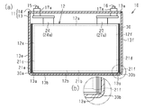
- the disassembled perspective view of the secondary battery of embodiment. is sectional drawing of the secondary battery of FIG. 1, (b) is the elements on larger scale of (a).
- the secondary battery 10 that is a power storage device includes a case 11.
- the secondary battery 10 includes an electrode assembly 12 accommodated in a case 11.
- the case 11 includes a rectangular parallelepiped case main body 13 and a rectangular flat cover 14 that covers the opening 13 a of the case main body 13.
- Both the case body 13 and the lid 14 are made of metal (for example, stainless steel or aluminum).
- the secondary battery 10 of the present embodiment is a square battery whose outer shape is a square.
- the secondary battery 10 of the present embodiment is a lithium ion battery.
- the case body 13 includes a bottom wall 13b (see FIG. 2A) and first to fourth wall portions 13c to 13f connected to the bottom wall 13b.
- the first wall portion 13c and the second wall portion 13d are wall portions connected to the two long edges of the bottom wall 13b, respectively, and are disposed so as to face each other.
- the third wall portion 13e extends between the first end portion of the first wall portion 13c and the first end portion of the second wall portion 13d
- the fourth wall portion 13f extends from the second end portion of the first wall portion 13c and the first end portion.
- the second wall 13d extends between the second ends.
- the 3rd wall part 13e and the 4th wall part 13f are arrange
- the case body 13 has a rounded corner portion 13g, which is a curved corner, at a portion where the inner surface of the bottom wall 13b and the inner surfaces of the first to fourth wall portions 13c to 13f intersect.
- the case body 13 is manufactured by plastically deforming a metal plate by plastic working such as deep drawing or impact pressing.
- the curved round corner 13g is unavoidably formed during plastic working.
- the secondary battery 10 includes a positive electrode terminal 15 and a negative electrode terminal 16 for taking out electricity from the electrode assembly 12.
- the lid 14 has two holes 14a that are arranged at intervals in the longitudinal direction.
- the positive terminal 15 and the negative terminal 16 protrude from the case 11 through the two holes 14a.
- an annular insulating ring 17 a for insulating the terminals 15 and 16 from the case 11 is attached to the positive terminal 15 and the negative terminal 16, respectively.
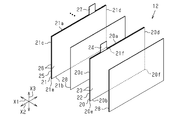
- the electrode assembly 12 includes a plurality of rectangular sheet-like positive electrodes 20 as first electrodes, a plurality of rectangular sheet-like negative electrodes 21 as second electrodes, and a rectangular sheet-like shape. And a plurality of separators 28.
- the separator 28 is disposed between the positive electrode 20 and the negative electrode 21 to insulate the positive electrode 20 and the negative electrode 21 from each other.
- the electrode assembly 12 has a structure in which the positive electrode 20 and the negative electrode 21 are alternately stacked with the separator 28 interposed therebetween.
- the electrode assembly 12 has a rectangular parallelepiped shape.
- the positive electrode 20 includes a positive electrode metal foil (for example, an aluminum foil) 22 that is a rectangular sheet-shaped current collector, and two positive electrode active material layers 23 disposed on both surfaces of the positive electrode metal foil 22.
- the positive electrode 20 includes a first edge portion 20a and a second edge portion 20b that are two edge portions along two long sides located on opposite sides.
- the positive electrode 20 has a rectangular positive electrode tab 24 protruding from a part of the first edge 20a.
- the positive electrode active material layer 23 is not disposed on both surfaces of the positive electrode tab 24.
- the positive electrode tab 24 is integrally formed with the positive electrode metal foil 22. That is, the positive electrode tab 24 is a portion of the positive electrode metal foil 22 where the positive electrode active material layer 23 is not disposed.
- the positive electrode 20 includes a third edge 20c extending between the first ends of the first edge 20a and the second edge 20b, and a distance between the second ends of the first edge 20a and the second edge 20b. And a fourth edge portion 20d extending in the direction. The fourth edge 20d is located on the opposite side of the third edge 20c.
- the positive electrode 20 includes a first corner 20e where the second edge 20b and the third edge 20c intersect, and a second where the second edge 20b and the fourth edge 20d intersect. And a corner 20f.
- the negative electrode 21 has a negative electrode metal foil (for example, copper foil) 25 that is a rectangular sheet-shaped current collector, and two negative electrode active material layers 26 disposed on both surfaces of the negative electrode metal foil 25, respectively.
- the negative electrode active material layer 26 is formed by applying an active material paste, in which an active material, a conductive additive, a solvent, and a binder are mixed, to a current collector and then drying it.
- the active material of this embodiment is silicon. By using silicon as the active material, for example, the capacity of the secondary battery 10 can be increased compared to the case of using carbon.
- the negative electrode active material layer 26 containing silicon has a large amount of expansion when the secondary battery 10 is charged and a large amount of shrinkage when discharged.
- the negative electrode 21 includes a first edge 21a and a second edge 21b that are two edges along two long sides.
- the negative electrode 21 has a rectangular negative electrode tab 27 protruding from a part of the first edge 21a.
- the negative electrode active material layer 26 is not disposed on both surfaces of the negative electrode tab 27.
- the negative electrode tab 27 is integrally formed with the negative electrode metal foil 25. That is, the negative electrode tab 27 is a portion of the negative electrode metal foil 25 where the negative electrode active material layer 26 is not disposed.
- the negative electrode 21 includes a third edge 21c extending between the first ends of the first edge 21a and the second edge 21b and a distance between the second ends of the first edge 21a and the second edge 21b. And a fourth edge portion 21d extending in the direction.
- the fourth edge 21d is located on the opposite side of the third edge 21c.
- the negative electrode 21 is a second portion where the first corner portion 21e where the second edge portion 21b and the third edge portion 21c intersect, and a portion where the second edge portion 21b and the fourth edge portion 21d intersect.
- a corner portion 21f the direction orthogonal to the surface of the negative electrode 21 (the thickness direction of the negative electrode 21) is defined as a first direction X1.
- the direction in which the first and second edge portions 21a and 21b extend is defined as a second direction X2
- the direction in which the third and fourth edge portions 21c and 21d extend is defined as a third direction X3.
- the plurality of positive electrodes 20 are stacked such that the respective positive electrode tabs 24 are aligned in the stacking direction of the electrode assembly 12.
- the plurality of negative electrodes 21 are stacked so that the respective negative electrode tabs 27 are aligned in the stacking direction of the electrode assemblies 12 so as not to overlap the positive electrode tabs 24.
- the some positive electrode tab 24 is folded so that it may mutually contact within the range from the one end of the lamination direction in the electrode assembly 12 to the other end, and the positive electrode tab group 24a is formed.
- the positive electrode terminal 15 is electrically joined to the positive electrode tab group 24a.
- the plurality of negative electrode tabs 27 are folded so as to contact each other within a range from one end to the other end in the stacking direction of the electrode assembly 12, thereby forming a negative electrode tab group 27 a.
- the negative electrode terminal 16 is electrically connected to the negative electrode tab group 27a.
- the electrode assembly 12 includes a tab-side end surface 12 a that is an end surface facing the lid 14. From the tab side end surface 12a, the positive electrode tab group 24a and the negative electrode tab group 27a protrude.
- the electrode assembly 12 includes a bottom-side end surface 12b that is an end surface facing the inner surface of the bottom wall 13b of the case body 13.
- the bottom-side end surface 12b is formed by the second edges 20b and 21b of the stacked positive electrode 20 and negative electrode 21.
- the electrode assembly 12 has a first side surface 12c that is an end surface facing the inner surface of the first wall portion 13c of the case main body 13 and a second end surface that is opposed to the inner surface of the second wall portion 13d of the case main body 13. And a side surface 12d.
- the electrode assembly 12 includes a third side surface 12e that is an end surface facing the inner surface of the third wall portion 13e of the case main body 13, and a fourth side surface 12f that is an end surface facing the inner surface of the fourth wall portion 13f of the case main body 13.
- the third side surface 12 e is formed by the third edge portions 20 c and 21 c of the stacked positive electrode 20 and negative electrode 21.
- the fourth side surface 12 f is formed by the fourth edge portions 20 d and 21 d of the stacked positive electrode 20 and negative electrode 21.
- Such an electrode assembly 12 is accommodated in an insulating film 30 which is a bag formed of an insulating sheet.
- the positive electrode 20 and the negative electrode 21 during charging / discharging of the secondary battery 10 will be described.
- the positive electrode active material layer 23 of the positive electrode 20 and the negative electrode active material layer 26 of the negative electrode 21 undergo volume changes in the second direction X2 and the third direction X3. That is, when the secondary battery 10 is charged, the positive electrode active material layer 23 and the negative electrode active material layer 26 expand in the second direction X2 and the third direction X3, and when the secondary battery 10 is discharged, the positive electrode active material.
- the layer 23 and the negative electrode active material layer 26 contract in the second direction X2 and the third direction X3.
- the positive electrode active material layer 23 and the negative electrode active material layer 26 try to cause a volume change (expansion and contraction) in the first direction X1
- the secondary battery 10 is charged / discharged by a restraining jig (not shown). Since it is performed in a state where the electrode assembly 12 is constrained in the first direction X1, the amount of expansion and contraction in the first direction X1 is sufficiently small.
- the positive electrode active material layer 23 and the negative electrode active material layer 26 expand, the positive electrode metal foil 22 of the positive electrode 20 and the negative electrode metal foil 25 of the negative electrode 21 also expand in the second direction X2 and the third direction X3.
- a load is applied to the first portion 30a of the insulating film 30 from the first corner portions 20e and 21e of the positive electrode 20 and the negative electrode 21.
- a load is applied to the second portion 30 b of the insulating film 30 from the second corner portions 20 f and 21 f of the positive electrode 20 and the negative electrode 21.
- the insulating film 30 is an insulating sheet for insulating the electrode assembly 12 from the metal case 11.
- the puncture strength of the insulating film 30 is set to 30N or more and 70N or less.
- the insulating film 30 of this embodiment is made of polypropylene (PP) having a thickness of 150 ⁇ m, and the piercing strength is 58N.
- the piercing strength is measured by the following method.
- the restraining tool includes two restraining plates, a bolt that connects the two restraining plates, and a nut that is screwed to the bolt.
- Each constraining plate includes a through hole.
- Each constraining plate includes an annular silicon rubber attached to one side.
- Each through hole communicates with the inner periphery of the corresponding silicon rubber.
- one restraining plate is disposed so that the silicon rubber faces one surface of the insulating film 30, and the other restraining plate has the silicon rubber facing the other surface of the insulating film 30.
- the two restraining plates restrain the insulating film 30 via silicon rubber.
- the insulating film 30 is restrained in a stretched state (a state without wrinkles and deflection).
- a nail (not shown) is lowered with respect to the restrained insulating film 30 at a constant speed (25 mm / min), and a load is applied to the insulating film 30.
- the nail has a diameter of 8 mm and has a tapered portion at the tip.
- the inclination angle of the tapered portion with respect to the central axis of the nail is 60 degrees.
- the load immediately after the nail contacts the insulating film 30 and immediately before the tip of the nail penetrates the insulating film 30 is measured.
- the measured load is the puncture strength. That is, the piercing strength is a load applied to the insulating film 30 immediately before a hole is opened in the insulating film 30 by a nail.
- the piercing strength of the insulating film 30 is smaller than 30N, it is not preferable because the insulating film 30 is likely to be broken by the expansion of the positive electrode 20 and the negative electrode 21 described above.
- the degree of expansion of the positive electrode 20 and the negative electrode 21 is large and the load applied to the insulating film 30 from each corner 20e, 20f, 21e, 21f of the positive electrode 20 and the negative electrode 21 exceeds 70 N, the entire electrode assembly 12 is Move toward the lid 14.
- the insulating film 30 is not sandwiched between the corner portions 20e, 20f, 21e, 21f of the positive electrode 20 and the negative electrode 21 and the round corner portion 13g of the case body 13, and the insulating film 30 is torn.
- the piercing strength of the insulating film 30 may be 70 N or less.
- the piercing strength of the insulating film 30 increases as the thickness of the insulating film 30 increases.
- the insulating film 30 becomes thicker, it is necessary to reduce the volume of the electrode assembly 12 that occupies the case 11, and the capacity of the secondary battery 10 is reduced. Therefore, for example, in the case of the insulating film 30 made of polypropylene (PP), it is preferable to set the thickness to 120 ⁇ m or more and 150 ⁇ m or less in consideration of both the piercing strength of the insulating film 30 and the capacity of the secondary battery 10.
- PP polypropylene
- the insulating film 30 of the present embodiment is formed into a bag shape by folding and welding one insulating film 30.
- the insulating film 30 covers five surfaces (the bottom side end surface 12b and the first to fourth side surfaces 12c to 12f) excluding the tab side end surface 12a of the electrode assembly 12.
- the insulating film 30 includes a first portion 30a that is a portion that covers the first corner portions 20e and 21e of the positive electrode 20 and the negative electrode 21, and a second portion 30b that is a portion that covers the second corner portions 20f and 21f. .
- the first portion 30 a is located between the first corner portions 20 e and 21 e and the round corner portion 13 g of the case main body 13
- the second portion 30b is located between the second corner portions 20f and 21f and the round corner portion 13g of the case body 13 (see FIG. 2B).
- the puncture strength of the insulating film 30 of this embodiment is set to 30 N or more and 70 N or less, even if the positive electrode 20 and the negative electrode 21 expand, the first part 30 a and the second part 30 b are not easily broken. .
- the puncture strength of the insulating film 30 is set to 30N or more and 70N or less. Accordingly, when the secondary battery 10 is charged, the positive electrode 20 and the negative electrode 21 expand, and the first corners 20e and 21e and the second corners 20f and 21f of the positive electrode 20 and the negative electrode 21 are the first of the insulating film 30, respectively.
- the first portion 30a When pressed against the first portion 30a and the second portion 30b, the first portion 30a is sandwiched between the first corner portions 20e, 21e and the round corner portion 13g of the case body 13, or the second portion 30b is Even if the insulating film 30 is sandwiched between the second corner portions 20f and 21f and the round corner portion 13g of the case body 13, the insulating film 30 is hardly broken.
- the insulating film 30 is made of polypropylene (PP) having a thickness of 120 ⁇ m or more and 150 ⁇ m or less. Since the puncture strength increases as the thickness of the insulating film 30 increases, the tearing can be suppressed by increasing the thickness of the insulating film 30. On the other hand, as the insulating film 30 becomes thicker, the volume for housing the electrode assembly 12 in the case 11 becomes smaller, and the capacity of the secondary battery 10 decreases. Therefore, by setting both the piercing strength of the insulating film 30 and the capacity of the secondary battery 10 and setting the thickness of the insulating film 30, the tearing of the insulating film 30 is suppressed while suppressing the capacity reduction of the secondary battery 10. it can. Further, by making the insulating film 30 made of polypropylene (PP), for example, the production cost of the insulating film 30 can be suppressed as compared with the case of making polyphenylene sulfide (PPS).
- PP polypropylene
- the negative electrode active material layer 26 contains silicon, the amount of expansion is larger than that of the negative electrode active material layer not containing silicon. Therefore, the load applied to the insulating film 30 from the corners 21e and 21f of the negative electrode 21 is also increased. For this reason, it is good to suppress the tear of the insulating film 30 by employ
- the current collector is not limited to the one provided with the positive electrode metal foil 22 and the negative electrode metal foil 25 as long as the positive electrode active material layer 23 and the negative electrode active material layer 26 can be formed.
- the current collector may be a woven or net-like sheet.
- the positive electrode 20 may have a structure in which the positive electrode active material layer 23 is disposed on one surface of the positive electrode metal foil 22.
- the negative electrode 21 may have a configuration in which the negative electrode active material layer 26 is disposed on one side of the negative electrode metal foil 25.
- the outer shape of one polarity electrode of the positive electrode 20 and the negative electrode 21 may be larger than the outer shape of the other polarity electrode.
- the insulating film 30 is sandwiched between the corner of the electrode having the larger outer shape and the round corner 13 g of the case body 13.
- the active material of the negative electrode active material layer 26 may be carbon, or may include both silicon and carbon.
- the type and ratio of the material used for the active material may be changed according to the capacity of the secondary battery 10.
- the puncture strength of the insulating film 30 of the above embodiment was 58N, but may be appropriately changed within a range of 30N or more and 70N or less.
- the insulating film 30 of the above embodiment was made of polypropylene (PP) having a thickness of 150 ⁇ m, but the material and thickness of the insulating film 30 may be changed as appropriate within a range where the puncture strength is 30 or more and 70 N or less.
- Examples of other materials for the insulating film 30 include polyphenylene sulfide (PPS) and polyethylene (PE).
- the electrode assembly 12 may be covered with a plurality of insulating films 30 formed in a bag shape.
- the method of forming the insulating film 30 in a bag shape is not limited to welding.
- the electrode assembly 12 is covered with a single insulating film 30. And you may affix with the tape so that the part which protruded from the electrode assembly 12 in the insulating film 30 may overlap with the part which has covered the electrode assembly 12.
- FIG. As another method, the electrode assembly 12 is housed in a bag-like insulating film 30 that is slightly larger than the electrode assembly 12, and then the insulating film 30 is thermally contracted, thereby the electrode assembly 12 and the insulating film. 30 may be brought into close contact with each other.
- the secondary battery 10 may be a lithium ion secondary battery or another secondary battery. In short, any ion may be used as long as ions move between the active material for the positive electrode and the active material for the negative electrode and charge is transferred.
- the power storage device can also be applied to power storage devices other than secondary batteries, such as capacitors.
Landscapes
- Chemical & Material Sciences (AREA)
- Chemical Kinetics & Catalysis (AREA)
- Electrochemistry (AREA)
- General Chemical & Material Sciences (AREA)
- Engineering & Computer Science (AREA)
- Materials Engineering (AREA)
- Manufacturing & Machinery (AREA)
- Cell Separators (AREA)
- Secondary Cells (AREA)
- Sealing Battery Cases Or Jackets (AREA)
- Battery Electrode And Active Subsutance (AREA)
Abstract
蓄電装置は、矩形シート状の複数の正極電極と、矩形シート状の複数の負極電極と、複数のセパレータとを有し、前記セパレータで前記正極電極と前記負極電極とを絶縁した状態で、前記正極電極及び前記負極電極を交互に積層した直方体状の電極組立体と、前記電極組立体を収容する直方体状のケースと、前記電極組立体と前記ケースとの間に配置され、前記電極組立体を前記ケースから絶縁するように前記電極組立体を収容する袋状の絶縁シートと、を備える。前記絶縁シートの突き刺し強度は、30N以上かつ70N以下である。
Description
本発明は、電極組立体と、電極組立体を収容するケースと、電極組立体をケースから絶縁する絶縁シートとを備える蓄電装置に関する。
EV(Electric Vehicle)やPHV(Plug-in Hybrid Vehicle)などの車両には、走行用モータへの供給電力を蓄える蓄電装置としての二次電池が搭載されている。二次電池は、矩形シート状の正極電極と矩形シート状の負極電極とが交互に積層された電極組立体と、当該電極組立体を収容する直方体状のケースとを備える。また、電極組立体を袋状に形成された絶縁シートによって覆うことで、電極組立体をケースから絶縁している(特許文献1参照)。
正極電極及び負極電極は、二次電池の充電時に膨張し、放電時に収縮する。そのため、膨張した正極電極及び負極電極の角部とケースの内面との間に絶縁シートが挟まれたときに、絶縁シートが破れるおそれがある。絶縁シートが破れると、電極組立体とケースが短絡してしまう。
本発明の目的は、電極の膨張による絶縁シートの破れを抑制できる蓄電装置を提供することにある。
上記問題点を解決するための蓄電装置は、矩形シート状の複数の正極電極と、矩形シート状の複数の負極電極と、複数のセパレータとを有し、前記セパレータで前記正極電極と前記負極電極とを絶縁した状態で、前記正極電極及び前記負極電極を交互に積層した直方体状の電極組立体と、前記電極組立体を収容する直方体状のケースと、前記電極組立体と前記ケースとの間に配置され、前記電極組立体を前記ケースから絶縁するように前記電極組立体を収容する袋状の絶縁シートと、を備える。前記絶縁シートの突き刺し強度は、30N以上かつ70N以下である。
以下、蓄電装置を具体化した一実施形態を図1~図3にしたがって説明する。
図1及び図2(a)に示すように、蓄電装置である二次電池10は、ケース11を備える。二次電池10は、ケース11に収容された電極組立体12を備える。ケース11は、直方体状のケース本体13と、ケース本体13の開口部13aを覆う矩形平板状の蓋14とを有する。ケース本体13と蓋14とは、何れも金属製(例えば、ステンレスまたはアルミニウム)である。また、本実施形態の二次電池10は、その外形が角型の角型電池である。また、本実施形態の二次電池10は、リチウムイオン電池である。
図1及び図2(a)に示すように、蓄電装置である二次電池10は、ケース11を備える。二次電池10は、ケース11に収容された電極組立体12を備える。ケース11は、直方体状のケース本体13と、ケース本体13の開口部13aを覆う矩形平板状の蓋14とを有する。ケース本体13と蓋14とは、何れも金属製(例えば、ステンレスまたはアルミニウム)である。また、本実施形態の二次電池10は、その外形が角型の角型電池である。また、本実施形態の二次電池10は、リチウムイオン電池である。
ケース本体13は、底壁13b(図2(a)参照)と、底壁13bに繋がる第1~第4壁部13c~13fとを備える。第1壁部13c及び第2壁部13dは、それぞれ底壁13bの2つの長縁部に繋がる壁部であり、互いに対向するように配置される。第3壁部13eは第1壁部13cの第1端部及び第2壁部13dの第1端部の間に延び、第4壁部13fは第1壁部13cの第2端部及び第2壁部13dの第2端部の間に延びる。第3壁部13eと第4壁部13fは、互いに対向するように配置される。図2に示すように、ケース本体13は、底壁13bの内面と第1~第4壁部13c~13fの内面とが交差する部分に、曲面状の角である丸角部13gを有する。ケース本体13は、深絞り加工またはインパクトプレス加工などの塑性加工によって金属板を塑性変形させることで製造されている。曲面状の丸角部13gは、塑性加工の際に不可避に形成される。
二次電池10は、電極組立体12から電気を取り出すための正極端子15と負極端子16とを備える。蓋14は、長手方向に間隔をあけて並ぶ2つの孔14aを有する。正極端子15及び負極端子16は、それぞれ2つの孔14aからケース11の外部に突出する。また、正極端子15及び負極端子16には、これらの端子15,16をケース11から絶縁するための環状の絶縁リング17aがそれぞれ取り付けられている。
図3に示すように、電極組立体12は、第1の電極である矩形シート状の複数の正極電極20と、第2の電極である矩形シート状の複数の負極電極21と、矩形シート状の複数のセパレータ28とを備える。セパレータ28は、正極電極20と負極電極21との間に配置されることにより、正極電極20と負極電極21とを互いから絶縁する。電極組立体12は、セパレータ28を挟んで正極電極20及び負極電極21を交互に積層した構造を備える。電極組立体12は、直方体状をなす。
正極電極20は、矩形シート状の集電体である正極金属箔(例えばアルミニウム箔)22と、正極金属箔22の両面にそれぞれ配置される2つの正極活物質層23とを有する。正極電極20は、互いに反対側に位置する2つの長辺に沿う2つの縁部である第1縁部20a及び第2縁部20bを備える。正極電極20は、第1縁部20aの一部から突出した矩形状の正極タブ24を有する。正極タブ24の両面には正極活物質層23が配置されていない。正極タブ24は正極金属箔22と一体形成されている。すなわち、正極タブ24は、正極金属箔22のうち、正極活物質層23が配置されていない部分である。
正極電極20は、第1縁部20a及び第2縁部20bの第1端同士の間に延びる第3縁部20cと、第1縁部20a及び第2縁部20bの第2端同士の間に延びる第4縁部20dと、を備える。第4縁部20dは、第3縁部20cの反対側に位置する。正極電極20は、第2縁部20bと第3縁部20cとが交差する部分である第1角部20eと、第2縁部20bと第4縁部20dとが交差する部分である第2角部20fとを備える。
負極電極21は、矩形シート状の集電体である負極金属箔(例えば銅箔)25と、負極金属箔25の両面にそれぞれ配置される2つの負極活物質層26とを有する。負極活物質層26は、活物質、導電助剤、溶媒及びバインダを混合した活物質ペーストを集電体に塗布した後、乾燥させることで形成される。本実施形態の活物質はケイ素である。活物質にケイ素を用いることで、例えばカーボンを用いる場合と比較して、二次電池10の容量を増大させることができる。一方で、ケイ素を含む負極活物質層26は、二次電池10の充電時の膨張量及び放電時の収縮量が大きくなる。負極電極21は、2つの長辺に沿う2つの縁部である第1縁部21a及び第2縁部21bを備える。負極電極21は、第1縁部21aの一部から突出した矩形状の負極タブ27を有する。負極タブ27の両面には、負極活物質層26が配置されていない。負極タブ27は負極金属箔25と一体形成されている。すなわち、負極タブ27は、負極金属箔25のうち、負極活物質層26が配置されていない部分である。
負極電極21は、第1縁部21a及び第2縁部21bの第1端同士の間に延びる第3縁部21cと、第1縁部21a及び第2縁部21bの第2端同士の間に延びる第4縁部21dとを備える。第4縁部21dは、第3縁部21cの反対側に位置する。負極電極21は、第2縁部21bと第3縁部21cとが交差する部分である第1角部21eと、第2縁部21bと第4縁部21dとが交差する部分である第2角部21fとを備える。以下、負極電極21の面と直交する方向(負極電極21の厚さ方向)を第1方向X1とする。また、第1及び第2縁部21a,21bが延びる方向を第2方向X2とし、第3及び第4縁部21c,21dが延びる方向を第3方向X3とする。
図1に示すように、複数の正極電極20は、それぞれの正極タブ24が電極組立体12の積層方向に並ぶように積層される。同様に、複数の負極電極21は、それぞれの負極タブ27が、正極タブ24と重ならないように、電極組立体12の積層方向に並ぶように積層される。そして、複数の正極タブ24は、電極組立体12における積層方向の一端から他端までの範囲内で互いに接触するように折り重ねられることにより、正極タブ群24aを形成する。正極タブ群24aには、正極端子15が電気的に接合される。また、複数の負極タブ27も同様に、電極組立体12における積層方向の一端から他端までの範囲内で互いに接触するように折り重ねられることにより、負極タブ群27aを形成する。負極タブ群27aには、負極端子16が電気的に接続される。
電極組立体12は、蓋14に対向する端面であるタブ側端面12aを備える。タブ側端面12aからは、正極タブ群24a及び負極タブ群27aが突出する。電極組立体12は、ケース本体13の底壁13bの内面に対向した端面である底側端面12bを備える。底側端面12bは、積層された正極電極20及び負極電極21の第2縁部20b,21bにより形成される。また、電極組立体12は、ケース本体13の第1壁部13cの内面に対向した端面である第1側面12cと、ケース本体13の第2壁部13dの内面に対向した端面である第2側面12dとを備える。電極組立体12は、ケース本体13の第3壁部13eの内面に対向した端面である第3側面12eと、ケース本体13の第4壁部13fの内面に対向した端面である第4側面12fとを備える。第3側面12eは、積層された正極電極20及び負極電極21の第3縁部20c,21cにより形成される。第4側面12fは、積層された正極電極20及び負極電極21の第4縁部20d,21dにより形成される。このような電極組立体12は、絶縁シートで形成される袋である絶縁フィルム30に収容されている。
ここで、二次電池10の充放電時の正極電極20及び負極電極21について説明する。
二次電池10の充放電を行うと、正極電極20の正極活物質層23及び負極電極21の負極活物質層26は、第2方向X2及び第3方向X3に体積変化を生じる。すなわち、二次電池10の充電を行うと、正極活物質層23及び負極活物質層26は第2方向X2及び第3方向X3へ膨張し、二次電池10の放電を行うと、正極活物質層23及び負極活物質層26は第2方向X2及び第3方向X3へ収縮する。なお、正極活物質層23及び負極活物質層26は第1方向X1にも体積変化(膨張及び収縮)を生じようとするが、一般に二次電池10の充放電は、図示しない拘束治具によって電極組立体12を第1方向X1に拘束した状態で行われるため、第1方向X1への膨張量及び収縮量は十分小さい。正極活物質層23及び負極活物質層26の膨張に伴い、正極電極20の正極金属箔22及び負極電極21の負極金属箔25も第2方向X2及び第3方向X3に膨張する。これにより、正極電極20及び負極電極21の第1角部20e,21eから絶縁フィルム30の第1部位30aに荷重が加わる。同様に、正極電極20及び負極電極21の第2角部20f,21fから絶縁フィルム30の第2部位30bに荷重が加わる。
二次電池10の充放電を行うと、正極電極20の正極活物質層23及び負極電極21の負極活物質層26は、第2方向X2及び第3方向X3に体積変化を生じる。すなわち、二次電池10の充電を行うと、正極活物質層23及び負極活物質層26は第2方向X2及び第3方向X3へ膨張し、二次電池10の放電を行うと、正極活物質層23及び負極活物質層26は第2方向X2及び第3方向X3へ収縮する。なお、正極活物質層23及び負極活物質層26は第1方向X1にも体積変化(膨張及び収縮)を生じようとするが、一般に二次電池10の充放電は、図示しない拘束治具によって電極組立体12を第1方向X1に拘束した状態で行われるため、第1方向X1への膨張量及び収縮量は十分小さい。正極活物質層23及び負極活物質層26の膨張に伴い、正極電極20の正極金属箔22及び負極電極21の負極金属箔25も第2方向X2及び第3方向X3に膨張する。これにより、正極電極20及び負極電極21の第1角部20e,21eから絶縁フィルム30の第1部位30aに荷重が加わる。同様に、正極電極20及び負極電極21の第2角部20f,21fから絶縁フィルム30の第2部位30bに荷重が加わる。
絶縁フィルム30は、電極組立体12を金属製のケース11と絶縁するための絶縁性のシートである。絶縁フィルム30の突き刺し強度は、30N以上かつ70N以下に設定される。本実施形態の絶縁フィルム30は、厚みが150μmのポリプロピレン(PP)製であり、突き刺し強度は58Nである。
突き刺し強度は、次の方法で測定される。まず、拘束具(図示せず)によって絶縁フィルム30を拘束する。拘束具は、2つの拘束板と、2つの拘束板を連結するボルトと、ボルトに螺合されるナットとを備える。各拘束板は、貫通孔を備える。各拘束板は、片面に取り付けられた円環状のシリコンゴムを備える。各貫通孔は、対応するシリコンゴムの内周と連通する。2つの拘束板のうち、一方の拘束板は、シリコンゴムが絶縁フィルム30の一方の面と対向するように配置され、他方の拘束板は、シリコンゴムが絶縁フィルム30の他方の面と対向するように配置される。この状態でボルトにナットを螺合することで、2つの拘束板はシリコンゴムを介して絶縁フィルム30を拘束する。絶縁フィルム30は、張った状態(皺及び撓みがない状態)で拘束される。次に、拘束された絶縁フィルム30に対して釘(図示せず)を一定速度(25mm/min)で降下させ、絶縁フィルム30に荷重を加えていく。釘は、φ8mmであり、先端にテーパ部を備える。釘の中心軸線に対するテーパ部の傾斜角度は60度である。そして、絶縁フィルム30に釘が接触した後であって、釘の先端が絶縁フィルム30を突き抜ける直前の荷重を測定する。測定された荷重が突き刺し強度である。つまり、突き刺し強度とは、釘によって絶縁フィルム30に孔が開く直前に絶縁フィルム30に加わっている荷重である。
絶縁フィルム30の突き刺し強度が30Nより小さい場合、上述した正極電極20及び負極電極21の膨張によって絶縁フィルム30に破れが発生する可能性が高く好ましくない。正極電極20及び負極電極21の膨張度合いが大きく、正極電極20及び負極電極21の各角部20e,20f,21e,21fから絶縁フィルム30に加わる荷重が70Nを超える場合、電極組立体12全体が蓋14の方へ移動する。これにより、絶縁フィルム30は、正極電極20及び負極電極21の各角部20e,20f,21e,21fとケース本体13の丸角部13gとの間で挟まれず、絶縁フィルム30に破れが発生する可能性は低い。このことから、絶縁フィルム30の突き刺し強度を70N以下にしてよい。
絶縁フィルム30の突き刺し強度は、絶縁フィルム30の厚みを厚くするほど強くなる。その一方で、絶縁フィルム30が厚くなるほどケース11内を占める電極組立体12の容積を小さくする必要があり、二次電池10の容量が低下してしまう。したがって、例えば、ポリプロピレン(PP)製の絶縁フィルム30の場合、絶縁フィルム30の突き刺し強度と二次電池10の容量との両方を加味した厚みとして120μm以上かつ150μm以下に設定することが好ましい。
本実施形態の絶縁フィルム30は、1枚の絶縁フィルム30を折り畳み、かつ溶着して袋状に形成されている。絶縁フィルム30は、電極組立体12のタブ側端面12aを除く5面(底側端面12b及び第1~第4側面12c~12f)を覆っている。絶縁フィルム30は、正極電極20及び負極電極21の第1角部20e,21eを覆う部分である第1部位30aと、第2角部20f,21fを覆う部分である第2部位30bとを有する。絶縁フィルム30に覆われた電極組立体12をケース本体13に収容した状態において、第1部位30aは、第1角部20e,21eとケース本体13の丸角部13gとの間に位置し、第2部位30bは、第2角部20f,21fとケース本体13の丸角部13gとの間に位置する(図2(b)参照)。
次に、本実施形態の作用について説明する。
本実施形態の絶縁フィルム30の突き刺し強度は30N以上かつ70N以下に設定されているため、正極電極20及び負極電極21が膨張したとしても第1部位30a及び第2部位30bに破れが生じにくくなる。
本実施形態の絶縁フィルム30の突き刺し強度は30N以上かつ70N以下に設定されているため、正極電極20及び負極電極21が膨張したとしても第1部位30a及び第2部位30bに破れが生じにくくなる。
次に、本実施形態の効果を記載する。
(1)絶縁フィルム30の突き刺し強度は30N以上かつ70N以下に設定される。よって、二次電池10の充電時に正極電極20及び負極電極21が膨張し、正極電極20及び負極電極21の第1角部20e,21e及び第2角部20f,21fがそれぞれ絶縁フィルム30の第1部位30a及び第2部位30bに押し当てられたときに、第1部位30aが第1角部20e,21eとケース本体13の丸角部13gとの間に挟まれたり、第2部位30bが第2角部20f,21fとケース本体13の丸角部13gの間に挟まれたりしても、絶縁フィルム30に破れが生じにくくなる。
(1)絶縁フィルム30の突き刺し強度は30N以上かつ70N以下に設定される。よって、二次電池10の充電時に正極電極20及び負極電極21が膨張し、正極電極20及び負極電極21の第1角部20e,21e及び第2角部20f,21fがそれぞれ絶縁フィルム30の第1部位30a及び第2部位30bに押し当てられたときに、第1部位30aが第1角部20e,21eとケース本体13の丸角部13gとの間に挟まれたり、第2部位30bが第2角部20f,21fとケース本体13の丸角部13gの間に挟まれたりしても、絶縁フィルム30に破れが生じにくくなる。
(2)絶縁フィルム30は、厚みが120μm以上かつ150μm以下のポリプロピレン(PP)製である。絶縁フィルム30の厚みが厚いほど、突き刺し強度は強くなるため、絶縁フィルム30の厚みを厚くすることで破れを抑制できる。その一方で、絶縁フィルム30が厚くなるほどケース11内で電極組立体12を収容するための容積が小さくなり、二次電池10の容量が低下してしまう。よって、絶縁フィルム30の突き刺し強度と二次電池10の容量の両方を加味して絶縁フィルム30の厚みを設定することで、二次電池10の容量低下を抑制しつつ絶縁フィルム30の破れを抑制できる。また、絶縁フィルム30をポリプロピレン(PP)製にすることで、例えば、ポリフェニレンサルファイド(PPS)製にする場合と比べて、絶縁フィルム30の生産コストを抑えられる。
(3)負極活物質層26は、ケイ素を含むため、ケイ素を含まない負極活物質層と比較して膨張量が大きい。よって、負極電極21の各角部21e,21fから絶縁フィルム30に加わる荷重も大きくなる。このため、突き刺し強度が30N以上かつ70N以下の絶縁フィルム30を採用することで絶縁フィルム30の破れを抑制するとよい。
なお、上記実施形態は、以下のように変更してもよい。
○ 集電体は、正極活物質層23及び負極活物質層26が形成できるものであれば、正極金属箔22及び負極金属箔25を備えるものに限定されない。例えば、集電体は、織物状または網状のシートであってもよい。
○ 集電体は、正極活物質層23及び負極活物質層26が形成できるものであれば、正極金属箔22及び負極金属箔25を備えるものに限定されない。例えば、集電体は、織物状または網状のシートであってもよい。
○ 正極電極20は、正極金属箔22の片面に正極活物質層23が配置された構造でもよい。同様に、負極電極21は、負極金属箔25の片面に負極活物質層26が配置された構成でもよい。
○ 正極電極20及び負極電極21の一方の極性の電極の外形を他方の極性の電極の外形よりも大きくしてもよい。この場合、絶縁フィルム30は、外形の大きい方の極性の電極の角部とケース本体13の丸角部13gの間に挟まれる。
○ 負極活物質層26の活物質は、カーボンでもよいし、シリコンとカーボンの両方を含んでもよい。活物質に用いる材料の種類や割合は、二次電池10の容量に応じて変更してよい。
○ 上記実施形態の絶縁フィルム30の突き刺し強度は58Nであったが、30N以上かつ70N以下の範囲で適宜変更してよい。
○ 上記実施形態の絶縁フィルム30は、厚みが150μmのポリプロピレン(PP)製であったが、絶縁フィルム30の材料及び厚みは、突き刺し強度が30以上かつ70N以下となる範囲で適宜変更してよい。絶縁フィルム30の他の材料としては、例えば、ポリフェニレンサルファイド(PPS)やポリエチレン(PE)などが挙げられる。
○ 上記実施形態の絶縁フィルム30は、厚みが150μmのポリプロピレン(PP)製であったが、絶縁フィルム30の材料及び厚みは、突き刺し強度が30以上かつ70N以下となる範囲で適宜変更してよい。絶縁フィルム30の他の材料としては、例えば、ポリフェニレンサルファイド(PPS)やポリエチレン(PE)などが挙げられる。
○ 袋状に形成された複数枚の絶縁フィルム30で、電極組立体12を覆ってもよい。
○ 絶縁フィルム30を袋状に形成する方法は、溶着に限定されない。例えば、1枚の絶縁フィルム30によって電極組立体12を覆う。そして、絶縁フィルム30において電極組立体12からはみ出した部分を、電極組立体12を覆っている部分に重ねるようにテープで貼り付けてもよい。また、他の方法として、電極組立体12より一回り大きい袋状の絶縁フィルム30の中に電極組立体12を収納し、その後で絶縁フィルム30を熱収縮させることで電極組立体12と絶縁フィルム30とを密着させてもよい。
○ 絶縁フィルム30を袋状に形成する方法は、溶着に限定されない。例えば、1枚の絶縁フィルム30によって電極組立体12を覆う。そして、絶縁フィルム30において電極組立体12からはみ出した部分を、電極組立体12を覆っている部分に重ねるようにテープで貼り付けてもよい。また、他の方法として、電極組立体12より一回り大きい袋状の絶縁フィルム30の中に電極組立体12を収納し、その後で絶縁フィルム30を熱収縮させることで電極組立体12と絶縁フィルム30とを密着させてもよい。
○ 二次電池10は、リチウムイオン二次電池でもよいし、他の二次電池であってもよい。要は、正極用の活物質と負極用の活物質との間をイオンが移動するとともに電荷の授受を行うものであればよい。
○ 蓄電装置は、例えばキャパシタなど、二次電池以外の蓄電装置にも適用可能である。
Claims (3)
- 矩形シート状の複数の正極電極と、矩形シート状の複数の負極電極と、複数のセパレータとを有し、前記セパレータで前記正極電極と前記負極電極とを絶縁した状態で、前記正極電極及び前記負極電極を交互に積層した直方体状の電極組立体と、
前記電極組立体を収容する直方体状のケースと、
前記電極組立体と前記ケースとの間に配置され、前記電極組立体を前記ケースから絶縁するように前記電極組立体を収容する袋状の絶縁シートと、
を備えた蓄電装置であって、
前記絶縁シートの突き刺し強度は、30N以上かつ70N以下である蓄電装置。 - 前記絶縁シートは、120μm以上かつ150μm以下の厚みを有するポリプロピレン製である請求項1に記載の蓄電装置。
- 前記負極電極は、集電体及び該集電体の両面又は片面に配置される活物質層を有し、
前記活物質層は、ケイ素を含む請求項1又は請求項2に記載の蓄電装置。
Applications Claiming Priority (2)
| Application Number | Priority Date | Filing Date | Title |
|---|---|---|---|
| JP2017-060855 | 2017-03-27 | ||
| JP2017060855A JP2018163817A (ja) | 2017-03-27 | 2017-03-27 | 蓄電装置 |
Publications (1)
| Publication Number | Publication Date |
|---|---|
| WO2018180475A1 true WO2018180475A1 (ja) | 2018-10-04 |
Family
ID=63675402
Family Applications (1)
| Application Number | Title | Priority Date | Filing Date |
|---|---|---|---|
| PCT/JP2018/009836 Ceased WO2018180475A1 (ja) | 2017-03-27 | 2018-03-14 | 蓄電装置 |
Country Status (2)
| Country | Link |
|---|---|
| JP (1) | JP2018163817A (ja) |
| WO (1) | WO2018180475A1 (ja) |
Cited By (1)
| Publication number | Priority date | Publication date | Assignee | Title |
|---|---|---|---|---|
| WO2023197162A1 (zh) * | 2022-04-12 | 2023-10-19 | 宁德时代新能源科技股份有限公司 | 电池单体、电池及用电设备 |
Citations (3)
| Publication number | Priority date | Publication date | Assignee | Title |
|---|---|---|---|---|
| JP2012195122A (ja) * | 2011-03-16 | 2012-10-11 | Hitachi Maxell Energy Ltd | 非水電解液二次電池 |
| JP2013222504A (ja) * | 2012-04-12 | 2013-10-28 | Toyota Industries Corp | 蓄電装置 |
| JP2015228359A (ja) * | 2014-05-02 | 2015-12-17 | 住友電気工業株式会社 | 角型蓄電デバイス、および角型蓄電デバイスの製造方法 |
-
2017
- 2017-03-27 JP JP2017060855A patent/JP2018163817A/ja active Pending
-
2018
- 2018-03-14 WO PCT/JP2018/009836 patent/WO2018180475A1/ja not_active Ceased
Patent Citations (3)
| Publication number | Priority date | Publication date | Assignee | Title |
|---|---|---|---|---|
| JP2012195122A (ja) * | 2011-03-16 | 2012-10-11 | Hitachi Maxell Energy Ltd | 非水電解液二次電池 |
| JP2013222504A (ja) * | 2012-04-12 | 2013-10-28 | Toyota Industries Corp | 蓄電装置 |
| JP2015228359A (ja) * | 2014-05-02 | 2015-12-17 | 住友電気工業株式会社 | 角型蓄電デバイス、および角型蓄電デバイスの製造方法 |
Cited By (1)
| Publication number | Priority date | Publication date | Assignee | Title |
|---|---|---|---|---|
| WO2023197162A1 (zh) * | 2022-04-12 | 2023-10-19 | 宁德时代新能源科技股份有限公司 | 电池单体、电池及用电设备 |
Also Published As
| Publication number | Publication date |
|---|---|
| JP2018163817A (ja) | 2018-10-18 |
Similar Documents
| Publication | Publication Date | Title |
|---|---|---|
| CN109326813B (zh) | 蓄电装置以及绝缘保持器 | |
| EP2337117B1 (en) | Secondary battery | |
| US10490795B2 (en) | Electricity storage device | |
| EP4333151B1 (en) | Electrode assembly and manufacturing method therefor, battery cell, battery, and electric apparatus | |
| US9871243B2 (en) | Electric accumulation device | |
| KR102874645B1 (ko) | 전극 조립체 및 이를 포함하는 이차 전지 | |
| JP6922980B2 (ja) | 蓄電装置 | |
| US9263761B2 (en) | Electrode assembly and rechargeable battery having the same | |
| JP7109231B2 (ja) | 角形非水電解質二次電池及びその製造方法 | |
| JP6878914B2 (ja) | 蓄電装置 | |
| JP6432952B1 (ja) | 電気化学セル | |
| WO2016084563A1 (ja) | 蓄電装置 | |
| JP2019053818A (ja) | 蓄電素子、及び蓄電素子を備える蓄電装置 | |
| JP2018018663A (ja) | 電気化学セル及び電気化学セルの製造方法 | |
| JP2016178028A (ja) | 電極体、及び電極体を備える蓄電素子 | |
| KR20150072107A (ko) | 미 열융착 라인을 통해 파우치형 케이스의 주변 부위가 접힌 이차전지 | |
| JP2018163817A (ja) | 蓄電装置 | |
| JP6874525B2 (ja) | 蓄電装置の製造方法 | |
| JP2016046009A (ja) | 蓄電装置 | |
| JP6911463B2 (ja) | 蓄電装置 | |
| JP2013251106A (ja) | 蓄電装置 | |
| JP2018170244A (ja) | 蓄電装置 | |
| JP6801371B2 (ja) | 蓄電装置 | |
| WO2016158398A1 (ja) | 角形二次電池およびその製造方法 | |
| WO2016076108A1 (ja) | 角形二次電池 |
Legal Events
| Date | Code | Title | Description |
|---|---|---|---|
| 121 | Ep: the epo has been informed by wipo that ep was designated in this application |
Ref document number: 18775713 Country of ref document: EP Kind code of ref document: A1 |
|
| NENP | Non-entry into the national phase |
Ref country code: DE |
|
| 122 | Ep: pct application non-entry in european phase |
Ref document number: 18775713 Country of ref document: EP Kind code of ref document: A1 |