WO2018174059A1 - 継電器評価装置 - Google Patents
継電器評価装置 Download PDFInfo
- Publication number
- WO2018174059A1 WO2018174059A1 PCT/JP2018/011035 JP2018011035W WO2018174059A1 WO 2018174059 A1 WO2018174059 A1 WO 2018174059A1 JP 2018011035 W JP2018011035 W JP 2018011035W WO 2018174059 A1 WO2018174059 A1 WO 2018174059A1
- Authority
- WO
- WIPO (PCT)
- Prior art keywords
- relay
- socket
- contact
- external connection
- current supply
- Prior art date
- Legal status (The legal status is an assumption and is not a legal conclusion. Google has not performed a legal analysis and makes no representation as to the accuracy of the status listed.)
- Ceased
Links
Images



Definitions
- the present invention relates to an apparatus for evaluating a relay applied to, for example, an electric device.
- various types of electrical equipment are applied to various types of equipment such as power equipment and water treatment equipment, and the characteristics of the electrical equipment may be examined and evaluated during maintenance or the like.
- a relay such as an auxiliary relay incorporated in an electrical device
- the characteristics (life, deterioration, etc.) of the relay are evaluated, for example, by measuring the contact resistance of the contact of the relay (hereinafter simply referred to as contact resistance as appropriate).
- contact resistance as appropriate.
- a relay evaluation device As a relay evaluation device (hereinafter simply referred to as “evaluation device” as appropriate), a relay mounting portion provided with a plurality of sockets (for example, a plurality of sockets having different arrangement patterns of various terminals) to be detachably mounted on a relay to be evaluated. And an external connection terminal provided in each socket corresponding to the contact terminal of the relay, and a resistance measuring unit that measures the contact resistance of the relay mounted in the socket.
- a resistance measuring unit of such an evaluation apparatus there is a configuration in which measurement is performed at a position close to the socket by a four-terminal method (position in the direction directly below in FIG. 1 and the like described later), and a contact point of a relay attached to the socket is provided. It is supposed that a minute contact resistance can be measured by detecting a voltage drop with respect to the constant current in a state where the constant current is supplied.
- noise for example, loop
- noise for example, loop
- a measurement error detection value error or the like
- the present invention has been made in view of the technical problems as described above, and is to provide a relay evaluation apparatus that can contribute to reliability of relay evaluation, simplification of the evaluation apparatus, and the like.
- the relay evaluation device is a creation that can solve the above-described problems, and one aspect thereof is a relay mounting portion provided with a plurality of sockets that are detachably mounted on the relay to be evaluated, and a contact terminal of the relay Corresponding to the external connection terminal provided in each socket, and a resistance measurement unit that measures the contact resistance of the contact of the relay mounted in the socket, the resistance measurement unit corresponds to the external connection terminal of each socket
- a relay wiring that is electrically connected in series for each contact terminal of the relay, and a current supply circuit that is electrically connected in series to the external connection terminal of the socket at one end of the electrical series of each socket,
- a voltage detection circuit electrically connected in series to the external connection terminal of the socket on the other end side of the electrical series among each socket, and a constant current corresponding to the socket in which the relay is mounted Is supplied from the current supply circuit, relay voltage drop for the constant current corresponding to the mounting socket, characterized in that it is detected by the voltage detection circuit.
- Each socket may be connected to a driving power source that drives a relay mounted in the socket.
- a switching circuit for selectively supplying a constant current corresponding to the socket on which the relay is mounted is interposed between the socket on one end of the electrical series among the sockets and the current supply circuit.
- a switching circuit that selectively detects a voltage drop with respect to a constant current corresponding to the socket in which the relay is mounted may be interposed between the socket on the other end side of the electrical series and the current supply circuit.
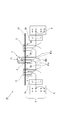
- the schematic block diagram for demonstrating 1 A of evaluation apparatuses which are an example of this embodiment.
- the schematic block diagram for demonstrating the evaluation apparatus 1B which is an example of this embodiment.
- the schematic block diagram for demonstrating the general evaluation apparatus 9A The schematic block diagram for demonstrating an example which attached the relay T to the evaluation apparatus 9A.
- the relay evaluation apparatus includes a relay wiring that connects an external connection terminal provided in each socket of the relay mounting portion in electrical series for each contact terminal of the corresponding relay, and an electrical connection among the sockets.
- a current supply circuit electrically connected in series to the external connection terminal of the socket at one end of the electrical series, and an electrical series connection to the external connection terminal of the socket at the other end of the electrical series among each socket.
- An evaluation device including a resistance measurement unit including a voltage detection circuit.
- the current supply circuit C (current supply terminals I1 ⁇ , to I2 ⁇ in FIGS. 5 and 6) is connected to the external connection of each socket 3.
- the voltage detection circuit V (voltage detection terminals V1 ⁇ , V2 ⁇ in FIGS.
- each contact terminal of the corresponding relay T is connected by a bus wiring system (hereinafter simply referred to as a bus circuit configuration) is exemplified.
- the resistance measurement unit 90 of the evaluation device 9B shown in FIGS. 7 and 8 also has a bus circuit configuration similar to that of the resistance measurement unit 9, and each of the terminals of the socket 3, the current supply circuit C, and the voltage detection circuit V Only the arrangement pattern, the arrangement pattern of contact terminals, the number of bus wirings, and the like are different.
- the sockets 3 are electrically connected to the current supply circuit C and the voltage detection circuit V in parallel, and the switching circuit (in comparison with the star wiring system)
- the switching circuit in comparison with the star wiring system
- the number of SSRs to be described later
- wirings can be suppressed.
- FIG. 6 when the relay T to be evaluated is attached to the socket 3 (the socket 3 in the center in the figure) and a constant current corresponding to the socket 3 is supplied from the current supply circuit C, The constant current flows as indicated by the solid arrow X in the figure while passing through the contacts (contacts by the contact terminals 1a and 1c in FIGS. This also flows through the loop circuit, and noise is generated in the evaluation apparatus.
- a voltage drop with respect to a constant current is detected in such a noise generation state, a measurement error is likely to occur, and there is a possibility that the reliability of the relay T is deteriorated.
- the external connection terminal 30 of each socket 3 is connected via the relay wiring 41 like the resistance measurement unit 4 of the evaluation apparatus 1A (details will be described later) shown in FIGS.
- the contact terminals of the corresponding relay T (contact terminals 1a to 1c in FIGS. 1 and 2) are electrically connected in series, and the current supply circuit C and the voltage detection circuit V are also electrically connected in series. It becomes the composition.
- the constant current is contacted (in FIG. It flows as indicated by the solid arrow X in FIG. 2 while passing through T1).
- the relay evaluation apparatus of the present embodiment has the above-described circuit configuration, technical common sense in various fields (for example, electric equipment fields in various facilities such as power facilities and water treatment facilities) is appropriately applied.
- the design can be modified, and examples thereof include the following.
- the evaluation apparatus 1A includes a relay mounting portion 10 provided with a plurality (three in the figure) of sockets 3, an external connection terminal 30 provided in each socket 3, and a relay to be evaluated mounted in the socket 3.
- the resistance measuring unit 4 that measures the contact resistance of T is mainly provided.
- Examples of the relay T that can be evaluated include auxiliary relays incorporated in electrical equipment of various facilities such as power facilities and water treatment facilities, but those of various forms (shapes, contacts, etc.) are applied as evaluation targets. Is possible.
- the contact T1 by the contact terminals 1a to 1c is provided.
- the relay mounting part 10 is provided with each socket 3 according to the form of the relay T to be evaluated distributed and arranged so that the relay T can be detachably mounted.
- the configuration in which the relay T is detachably attached to the socket 3 is not particularly limited.
- the relay T is provided on the outer peripheral side of the relay T and is electrically connected to the contact terminals 1a to 1c.
- a female terminal (not shown) (female terminal electrically connected to the external connection terminal 30) provided in the socket 3 and detachably fitted to the male terminal when mounted. Mounting configuration.
- a plurality of external connection terminals 30 of each socket 3 are provided in each socket 3 corresponding to the contact terminals 1a to 1c of the relay T (one at positions a to c in the figure). 3, when the relay T is mounted, the contact terminals 1a to 1c are electrically connected to each other, and the resistance measuring unit 4 can measure the contact resistance of the relay T.
- the external connection terminals 30 of the sockets 3 are connected to the relay terminals 41 (in the figure, the relay lines 41a to 41c; hereinafter, simply the relay lines) for the contact terminals 1a to 1c of the corresponding relay T. 41 is appropriately connected in series. Further, the current supply provided with current supply terminals I1 ⁇ and I2 ⁇ corresponding to each socket 3 with respect to the external connection terminal 30 of the socket 3 on one end side (the left side in the drawing in the drawing) of each socket 3 Circuit C is connected in electrical series.
- the external connection terminal 30 of the socket 3 on the other end side in the electrical series of each socket 3 (the right side in the drawing in the drawing) is provided with voltage detection terminals V1 ⁇ and V2 ⁇ corresponding to each socket 3.
- a voltage detection circuit V is electrically connected in series.
- the external connection terminals 30 of the sockets 3 are electrically connected in series to the contact terminals 1a to 1c of the corresponding relay T via the relay wiring 41, and the current supply circuit C and the voltage detection circuit V are connected. They are also electrically connected in series to form a so-called one-stroke wiring configuration.
- a switching circuit 5c is interposed between the socket 3 on one end side of the electrical series and the current supply circuit C as necessary, and the constant current from the current supply circuit C corresponding to the socket 3 to which the relay T is attached. It may be configured to selectively switch the current so that a constant current corresponding to the socket 3 in which the relay T is mounted can be supplied. In addition, a voltage detected by the voltage detection circuit V corresponding to the socket 3 to which the relay T is mounted is interposed between the socket 3 on the other end side of the electrical series and the voltage detection circuit V via the switching circuit 5v. A configuration in which the drop is selectively switched may be configured so that a voltage drop with respect to a constant current corresponding to the socket 3 to which the relay T is attached can be detected. Various types of switches can be applied to the switching circuits 5c and 5v, and one example thereof is a contactless relay such as an SSR.
- a control device (not shown) is controlled so that a constant current from the current supply circuit C can be selectively supplied to each socket 3, or a socket in which a relay T is mounted. Control is performed so that a voltage drop with respect to a constant current corresponding to 3 can be selectively detected, and control is performed so that contact resistance can be measured (calculated) using the constant current and the detected value.
- the relay T When the relay T is evaluated by the evaluation device 1A, for example, when the constant current corresponding to the socket 3 is supplied from the current supply circuit C in a state where the relay T is mounted in the socket 3 as shown in FIG. Flows as indicated by a solid line arrow X in FIG. At this time, in the resistance measurement unit 4, a phenomenon in which a constant current flows in a loop circuit such as a bus circuit configuration is suppressed, and noise hardly occurs. Then, in a state where a constant current is supplied from the current supply circuit C, a voltage drop with respect to the constant current corresponding to the socket 3 to which the relay T is mounted is detected by the voltage detection circuit V, so that contact at the contact of the relay T is achieved. Resistance can be measured.
- the evaluation device 1B is intended to evaluate the relay Tt driven by the drive power source P, and is configured to measure the contact resistance of the relay Tt by the resistance measuring unit 40.
- the relay Tt in the figure, it has a contact T1 by a plurality of contact terminals 1a to 1c, a contact T2 by a plurality of contact terminals 2a to 2c, and a power supply terminal v ⁇ to which a corresponding drive power supply P is connected. And a resistor r.
- the relay mounting portion 10 is configured to include sockets 31 to 33 in which the relay Tt can be detachably mounted instead of the socket 3.
- a plurality of sockets 31 to 33 are provided so as to correspond to the relay terminals Tt of the contact terminals 1a to 1c, 2a to 2c and the power supply terminal v ⁇ having different arrangement patterns (corresponding to three types in the figure) (see FIG. 3).
- Eight external connection terminals 30 in FIG. 4 are provided.
- the external connection terminals 30 of the sockets 31 to 33 are respectively connected to the relay wiring 41 (in the case shown in the figure, the relay wiring) for each of the contact terminals 1a to 1c and 2a to 2c of the corresponding relay Tt. 41a to 41c, 42a to 42c) are connected in electrical series. Further, the current supply circuit C connected in series to the external connection terminal 30 of the socket 31 on one end side of the electrical series among the sockets 31 to 33 (the left side in the drawing in the drawing) is connected to each socket 31 to 33. In this configuration, current supply terminals I1 ⁇ to I4 ⁇ corresponding to H.33 are provided.
- the voltage detection circuit V connected in series to the external connection terminal 30 of the socket 33 on the other end side of the electrical series among the sockets 31 to 33 (the right side in the figure) is connected to each socket 31.
- the voltage detection terminals V1 ⁇ to V4 ⁇ corresponding to .about.33 are provided.
- a so-called one-stroke wiring structure is obtained.
- a constant current from the current supply circuit C and a driving current for the relay Tt are selectively supplied to the sockets 31 to 33 by a control device (not shown). Control so that the voltage drop with respect to the constant current corresponding to the socket 31 to 33 mounted with the relay Tt can be selectively detected, or using the constant current and the detected value. For example, the contact resistance can be measured (calculated).
- the constant current is supplied to the contact T1 of the relay T. Will flow as indicated by the solid arrow X in FIG.
- the resistance measuring unit 40 as in the evaluation apparatus 1A shown in FIGS. 1 and 2, the phenomenon that a constant current flows through a loop circuit such as a bus circuit configuration is suppressed, and noise hardly occurs.
- the contact T1 of the relay Tt Contact resistance can be measured.
- the contact resistance of the contact T2 can also be measured by the same method as that for the contact T1.
Landscapes
- Measurement Of Resistance Or Impedance (AREA)
- Testing Electric Properties And Detecting Electric Faults (AREA)
Abstract
継電器装着部10の各ソケット3に設けられた外部接続端子30を、対応する継電器Tの接点端子1a~1c毎に、中継配線41により電気的直列に接続する。各ソケット3のうち電気的直列一端側のソケット3の外部接続端子30に対しては、電流供給回路Cを電気的直列に接続する。各ソケット3のうち電気的直列他端側のソケット3の外部接続端子30に対しては、電圧検出回路Vを電気的直列に接続する。これにより、電流供給回路Cと電圧検出回路Vとが電気的直列に接続された回路構成とする。そして、電流供給回路Cから定電流を供給した状態で、継電器Tが装着されたソケット3に対応した定電流に対する電圧降下を電圧検出回路Vにて検出することにより、継電器Tの接点T1における接触抵抗を測定する。
Description
本発明は、例えば電気機器に適用されている継電器を評価する装置に関するものである。
例えば電力設備や水処理設備等の各種設備には、種々の電気機器が適用されており、メンテナンス等により当該電気機器の特性を調べて評価することがある。電気機器に組み込まれる補助リレー等の継電器の場合、例えば継電器の接点の接触抵抗(以下、単に接触抵抗と適宜称する)等を測定する等により、当該継電器の特性(寿命,劣化等)を評価することが行われている(例えば特許文献1,2)。
継電器評価装置(以下、単に評価装置と適宜称する)としては、評価対象の継電器と着脱自在に装着するソケットが複数個(例えば各種端子の配列パターンが異なるソケットが複数個)設けられた継電器装着部と、継電器の接点端子に対応して各ソケットに設けられた外部接続端子と、ソケットに装着された継電器の接触抵抗を測定する抵抗測定部と、を備えたものが挙げられる。
このような評価装置の抵抗測定部としては、四端子法によりソケットに近接した位置(後述の図1等では図示直下方向の位置)で測定する構成があり、ソケットに装着された継電器の接点に定電流を供給した状態で当該定電流に対する電圧降下を検出して、微小な接触抵抗を測定できるものとされている。
前述のように継電器の接点に定電流を供給しながら電圧降下を検出する場合、評価装置の回路構成(配線構成,電気的接続の形態等)によっては、当該評価装置において少なからずノイズ(例えばループ回路によるノイズ)が発生することがある。特に接触抵抗のような微小な抵抗を測定する場合には、ノイズによって測定誤差(検出値の誤差等)が生じ易く、継電器評価の信頼性の低下を招く虞がある。このノイズの対策として、シールド電線等を適用したり回路構成を変更することも考えられるが、評価装置の複雑化(評価装置の大型化や高コスト化等)を招く虞がある。
本発明は、前述のような技術的課題に鑑みてなされたものであって、継電器評価の信頼性や評価装置の簡略化等に貢献可能な継電器評価装置を提供することにある。
この発明に係る継電器評価装置は、前記の課題を解決できる創作であり、その一態様は、評価対象の継電器と着脱自在に装着するソケットが複数個設けられた継電器装着部と、継電器の接点端子に対応して各ソケットに設けられた外部接続端子と、ソケットに装着された継電器の接点の接触抵抗を測定する抵抗測定部と、を備え、抵抗測定部は、各ソケットの外部接続端子を対応する継電器の接点端子毎に電気的直列に接続している中継配線と、各ソケットのうち電気的直列一端側のソケットの外部接続端子に対し、電気的直列に接続されている電流供給回路と、各ソケットのうち電気的直列他端側のソケットの外部接続端子に対し、電気的直列に接続されている電圧検出回路と、を備え、継電器が装着されたソケットに対応した定電流が、電流供給回路から供給され、継電器が装着されたソケットに対応した定電流に対する電圧降下が、電圧検出回路により検出されることを特徴とする。
各ソケットには、当該ソケットに装着された継電器を駆動する駆動電源が接続されても良い。また、各ソケットのうち電気的直列一端側のソケットと、電流供給回路と、の間には、継電器が装着されたソケットに対応した定電流を選択的に供給する切替回路が介在し、各ソケットのうち電気的直列他端側のソケットと、電流供給回路と、の間には、継電器が装着されたソケットに対応した定電流に対する電圧降下を選択的に検出する切替回路が介在しても良い。
以上示したように本発明によれば、継電器評価の信頼性や評価装置の簡略化等に貢献可能となる。
本発明の実施形態の継電器評価装置は、継電器装着部の各ソケットに設けられた外部接続端子を対応する継電器の接点端子毎に電気的直列に接続している中継配線と、各ソケットのうち電気的直列一端側のソケットの外部接続端子に対し電気的直列に接続されている電流供給回路と、各ソケットのうち電気的直列他端側のソケットの外部接続端子に対し電気的直列に接続されている電圧検出回路と、を備えた抵抗測定部を具備している評価装置である。これにより、電流供給回路と電圧検出回路とが電気的直列に接続された回路構成(以下、単に本回路構成と適宜称する)となっている。
このような本回路構成とは異なる一般的な構成としては、バス配線方式やスター配線方式等による構成が挙げられる。例えば図5,図6に示す評価装置9Aの抵抗測定部9のように、電流供給回路C(図5,図6中では電流供給端子I1±,~I2±)を、各ソケット3の外部接続端子(図5,図6中ではa~cに位置する3つの外部接続端子30)に対して、対応する継電器Tの接点端子(図5,図6中では3つの接点端子1a~1c)毎にバス配線方式で接続し、電圧検出回路V(図5,図6中では電圧検出端子V1±,V2±)においても、各ソケット3の外部接続端子に対して、電流供給回路Cと同様に対応する継電器Tの接点端子毎にバス配線方式で接続した構成(以下、単にバス回路構成と適宜称する)が挙げられる。図7,図8に示す評価装置9Bの抵抗測定部90においても、抵抗測定部9と同様のバス回路構成によるものであって、ソケット3,電流供給回路C,電圧検出回路Vの各端子の配列パターンや、接点端子の配列パターンや、バス配線数等が異なるのみである。
このようなバス回路構成は、各ソケット3同士が、電流供給回路Cや電圧検出回路Vに対しそれぞれ電気的並列に接続された関係となり、また、スター配線方式によるもの比較して、切替回路(例えば後述のSSR等)や配線等の数が抑えられるものとして知られている。しかしながら、例えば図6に示すように評価対象の継電器Tをソケット3(図中では図示中央部のソケット3)に装着し、そのソケット3に対応した定電流を電流供給回路Cから供給すると、当該定電流は、接点(図5,図6中では接点端子1a,1cによる接点)を経由しながら図中の実線矢印Xのように流れる他に、点線矢印Yのように回り込んだ複数個のループ回路にも流れてしまい、評価装置においてノイズが発生することとなる。このようなノイズ発生状態で定電流に対する電圧降下を検出する場合、測定誤差が生じ易く、継電器Tの評価において信頼性の低下を招く虞がある。
一方、本回路構成の場合、例えば図1,図2に示す評価装置1A(詳細は後述する)の抵抗測定部4のように、各ソケット3の外部接続端子30は、中継配線41を介して、対応する継電器Tの接点端子(図1,図2中では接点端子1a~1c)毎に電気的直列に接続され、電流供給回路Cと電圧検出回路Vとの間も電気的直列に接続された構成となる。これにより、例えば図2に示すように評価対象の継電器Tをソケット3に装着し、そのソケット3に対応した定電流を電流供給回路Cから供給すると、当該定電流は接点(図2中では接点T1)を経由しながら図2中の実線矢印Xのように流れることとなる。すなわち、本回路構成によれば、バス回路構成のようなループ回路に定電流が流れる現象は抑制され、ノイズが起こり難くなるため、測定誤差は抑制され、継電器Tの評価において所望の信頼性が得られ易くなる。
また、電流供給回路Cと各ソケット3との間、および電圧検出回路Vとソケット3との間においては、共通する配線等(中継配線41等)が存在していることから、バス回路構成などと比較すると切替回路(例えば後述のSSR等)や配線等の数が抑えられ、評価装置の簡略化(小型化や低コスト化等)にも貢献できることとなる。
近年、評価対象となり得る継電器の形態は多種多様(例えば100種を超える形態)であり、評価装置において各形態の継電器に対応できるようにすることが望まれているが、バス回路構成等による複雑化した制御装置の場合には、例えば誤配線を招いたり、メンテナンス業務に時間を費やしてしまう虞もある。一方、本実施形態のように簡略化した構成の評価装置であれば、例えば当該評価装置によるメンテナンス業務が容易になり、そのメンテナンス業務の時間短縮・質の向上や、各種設備の維持・管理のコスト削減等に貢献することも可能となる。
本実施形態の継電器評価装置は、前述のような本回路構成を持ったものであれば、種々の分野(例えば電力設備や水処理設備等の各種設備における電気機器分野)の技術常識を適宜適用して設計変形することが可能であり、その一例として以下に示すものが挙げられる。
≪本実施形態による継電器評価装置の一例≫
本実施形態の一例を図1,図2の評価装置1Aに基づいて説明する。評価装置1Aは、複数個(図中では3個)のソケット3が設けられた継電器装着部10と、各ソケット3に設けられた外部接続端子30と、ソケット3に装着された評価対象の継電器Tの接触抵抗を測定する抵抗測定部4と、を主として備えた構成となっている。
本実施形態の一例を図1,図2の評価装置1Aに基づいて説明する。評価装置1Aは、複数個(図中では3個)のソケット3が設けられた継電器装着部10と、各ソケット3に設けられた外部接続端子30と、ソケット3に装着された評価対象の継電器Tの接触抵抗を測定する抵抗測定部4と、を主として備えた構成となっている。
評価対象となり得る継電器Tとしては、例えば電力設備や水処理設備等の各種設備の電気機器に組み込まれる補助リレー等が挙げられるが、種々の形態(形状や接点等)のものを評価対象として適用することが可能である。図中の継電器Tの場合、接点端子1a~1cによる接点T1を備えた構成となっている。
継電器装着部10は、評価対象の継電器Tの形態等に応じた各ソケット3が、当該継電器Tを着脱自在に装着できるように分散配置して設けられたものである。ソケット3に継電器Tを着脱自在に装着する構成は、特に限定されるものではないが、その一例としては、継電器Tの外周側に設けられ接点端子1a~1cと電気的接続している図外のオス型端子と、ソケット3に設けられ装着時に当該オス型端子と着脱自在に嵌合する図外のメス型端子(外部接続端子30と電気的接続しているメス型端子)と、を備えた装着構成が挙げられる。
各ソケット3の外部接続端子30は、継電器Tの接点端子1a~1cに対応して各ソケット3に複数個(図中ではa~cの位置に1個)設けられたものであり、当該ソケット3に継電器Tが装着された場合に、対応する接点端子1a~1cと電気的接続し、抵抗測定部4によって継電器Tの接触抵抗を測定できるように構成されている。
抵抗測定部4においては、各ソケット3の外部接続端子30が、対応する継電器Tの接点端子1a~1c毎に、中継配線41(図中の場合、中継配線41a~41c;以下、単に中継配線41と適宜称する)により電気的直列に接続された構成となっている。また、各ソケット3のうち電気的直列一端側(図中では図示左側)のソケット3の外部接続端子30に対して、各ソケット3に対応する電流供給端子I1±,I2±を備えた電流供給回路Cが、電気的直列に接続されている。また、各ソケット3のうち電気的直列他端側(図中では図示右側)のソケット3の外部接続端子30に対しては、各ソケット3に対応する電圧検出端子V1±,V2±を備えた電圧検出回路Vが、電気的直列に接続されている。これにより、各ソケット3の外部接続端子30は、中継配線41を介して、対応する継電器Tの接点端子1a~1c毎に電気的直列に接続され、電流供給回路Cと電圧検出回路Vとの間も電気的直列に接続されて、いわゆる一筆書きの配線構成となっている。
電気的直列一端側のソケット3と電流供給回路Cとの間には、必要に応じて例えば切替回路5cが介在させ、継電器Tが装着されたソケット3に対応して電流供給回路Cからの定電流を選択的に切り替える構成とし、当該継電器Tが装着されたソケット3に対応した定電流を供給できるようにしても良い。また、電気的直列他端側のソケット3と電圧検出回路Vとの間においても、切替回路5vを介在させて、継電器Tが装着されたソケット3に対応して電圧検出回路Vで検出する電圧降下を選択的に切り替える構成とし、当該継電器Tが装着されたソケット3に対応した定電流に対する電圧降下を検出できるようにしても良い。これら切替回路5c,5vには、種々の形態のものを適用することができ、その一例としてはSSR等の無接点リレーを適用することが挙げられる。
また、抵抗測定部4においては、例えば図外の制御装置により、電流供給回路Cからの定電流を各ソケット3に対して選択的に供給できるように制御したり、継電器Tが装着されたソケット3に対応した定電流に対する電圧降下を選択的に検出できるように制御したり、当該定電流と検出値とを用いて接触抵抗を測定(演算)できるように制御することが挙げられる。
評価装置1Aにより継電器Tを評価する場合、例えば図2に示すように継電器Tがソケット3に装着された状態で、そのソケット3に対応した定電流を電流供給回路Cから供給すると、当該定電流は継電器Tの接点を経由しながら図2中の実線矢印Xのように流れることとなる。この際、抵抗測定部4においては、バス回路構成のようなループ回路に定電流が流れる現象は抑制され、ノイズも起こり難くなる。そして、電流供給回路Cから定電流を供給した状態で、当該継電器Tが装着されたソケット3に対応した定電流に対する電圧降下を電圧検出回路Vにて検出することにより、継電器Tの接点における接触抵抗を測定することができる。
≪本実施形態による継電器評価装置の他例≫
本実施形態の他例を図3,図4の評価装置1Bに基づいて説明する。なお、図1,図2と同様のものには同一符号を付す等により、その詳細な説明を適宜省略する。評価装置1Bは、駆動電源Pによって駆動する継電器Ttを評価対象とし、するものであり、その継電器Ttの接触抵抗を抵抗測定部40により測定する構成となっている。
本実施形態の他例を図3,図4の評価装置1Bに基づいて説明する。なお、図1,図2と同様のものには同一符号を付す等により、その詳細な説明を適宜省略する。評価装置1Bは、駆動電源Pによって駆動する継電器Ttを評価対象とし、するものであり、その継電器Ttの接触抵抗を抵抗測定部40により測定する構成となっている。
図中の継電器Ttの場合、複数個の接点端子1a~1cによる接点T1と、複数個の接点端子2a~2cによる接点T2と、対応する駆動電源Pが接続される電源端子v±を有した抵抗rと、を備えた構成となっている。
継電器装着部10は、ソケット3の替わりに、継電器Ttを着脱自在に装着できるソケット31~33を備えた構成となっている。これらソケット31~33は、それぞれ異なる配列パターンの接点端子1a~1c,2a~2c,電源端子v±の継電器Ttに対応(図中では3種類に対応)できるように、それぞれ複数個(図3,図4中では8個)の外部接続端子30が設けられている。
また、抵抗測定部40においては、各ソケット31~33の外部接続端子30が、対応する継電器Ttの接点端子1a~1c,2a~2c毎に、それぞれ中継配線41(図中の場合、中継配線41a~41c,42a~42c)により電気的直列に接続された構成となっている。また、各ソケット31~33のうち電気的直列一端側(図中では図示左側)のソケット31の外部接続端子30に対して電気的直列に接続されている電流供給回路Cは、各ソケット31~33に対応する電流供給端子I1±~I4±を備えた構成となっている。また、各ソケット31~33のうち電気的直列他端側(図中では図示右側)のソケット33の外部接続端子30に対して電気的直列に接続されている電圧検出回路Vは、各ソケット31~33に対応する電圧検出端子V1±~V4±を備えた構成となっている。これにより、図1,図2と同様に、いわゆる一筆書きの配線構成となっている。
また、抵抗測定部40においては、例えば抵抗測定部4と同様に図外の制御装置により、電流供給回路Cからの定電流や継電器Ttの駆動電流をソケット31~33に対して選択的に供給できるように制御したり、ソケット31~33のうち継電器Ttが装着されたものに対応した定電流に対する電圧降下を選択的に検出できるように制御したり、当該定電流と検出値とを用いて接触抵抗を測定(演算)できるように制御することが挙げられる。
評価装置1Bにおいて、例えば図4に示すように継電器Ttがソケット32に装着された状態で、そのソケット32に対応した定電流を電流供給回路Cから供給すると、当該定電流は継電器Tの接点T1を経由しながら図4中の実線矢印Xのように流れることとなる。この際、抵抗測定部40においては、図1,図2に示した評価装置1Aと同様に、バス回路構成のようなループ回路に定電流が流れる現象は抑制され、ノイズも起こり難くなる。そして、電流供給回路Cから定電流を供給した状態で、当該継電器Ttが装着されたソケット32に対応した定電流に対する電圧降下を電圧検出回路Vにて検出することにより、継電器Ttの接点T1における接触抵抗を測定することができる。接点T2の接触抵抗においても、接点T1の場合と同様の手法により、測定することが可能である。
以上、本発明において、記載された具体例に対してのみ詳細に説明したが、本発明の技術思想の範囲で多彩な変更等が可能であることは、当業者にとって明白なことであり、このような変更等が特許請求の範囲に属することは当然のことである。
Claims (3)
- 評価対象の継電器と着脱自在に装着するソケットが複数個設けられた継電器装着部と、
継電器の接点端子に対応して各ソケットに設けられた外部接続端子と、
ソケットに装着された継電器の接点の接触抵抗を測定する抵抗測定部と、を備え、
抵抗測定部は、
各ソケットの外部接続端子を対応する継電器の接点端子毎に電気的直列に接続している中継配線と、
各ソケットのうち電気的直列一端側のソケットの外部接続端子に対し、電気的直列に接続されている電流供給回路と、
各ソケットのうち電気的直列他端側のソケットの外部接続端子に対し、電気的直列に接続されている電圧検出回路と、を備え、
継電器が装着されたソケットに対応した定電流が、電流供給回路から供給され、
継電器が装着されたソケットに対応した定電流に対する電圧降下が、電圧検出回路により検出される、継電器評価装置。 - 各ソケットには、当該ソケットに装着された継電器を駆動する駆動電源が接続されている、請求項1記載の継電器評価装置。
- 各ソケットのうち電気的直列一端側のソケットと、電流供給回路と、の間には、継電器が装着されたソケットに対応した定電流を選択的に供給する切替回路が介在し、
各ソケットのうち電気的直列他端側のソケットと、電流供給回路と、の間には、継電器が装着されたソケットに対応した定電流に対する電圧降下を選択的に検出する切替回路が介在している、請求項1または2記載の継電器評価装置。
Applications Claiming Priority (2)
| Application Number | Priority Date | Filing Date | Title |
|---|---|---|---|
| JP2017054085A JP6771414B2 (ja) | 2017-03-21 | 2017-03-21 | 継電器評価装置 |
| JP2017-054085 | 2017-03-21 |
Publications (1)
| Publication Number | Publication Date |
|---|---|
| WO2018174059A1 true WO2018174059A1 (ja) | 2018-09-27 |
Family
ID=63585394
Family Applications (1)
| Application Number | Title | Priority Date | Filing Date |
|---|---|---|---|
| PCT/JP2018/011035 Ceased WO2018174059A1 (ja) | 2017-03-21 | 2018-03-20 | 継電器評価装置 |
Country Status (2)
| Country | Link |
|---|---|
| JP (1) | JP6771414B2 (ja) |
| WO (1) | WO2018174059A1 (ja) |
Citations (3)
| Publication number | Priority date | Publication date | Assignee | Title |
|---|---|---|---|---|
| JPH05256886A (ja) * | 1992-03-12 | 1993-10-08 | Fujitsu Ltd | 接触抵抗の測定装置とその測定方法 |
| JP2007183171A (ja) * | 2006-01-06 | 2007-07-19 | Chugoku Electric Power Co Inc:The | 配電線継電器単体試験装置および配電線継電器単体試験方法 |
| JP2010080094A (ja) * | 2008-09-24 | 2010-04-08 | Chugoku Electric Power Co Inc:The | リレー点検装置 |
-
2017
- 2017-03-21 JP JP2017054085A patent/JP6771414B2/ja active Active
-
2018
- 2018-03-20 WO PCT/JP2018/011035 patent/WO2018174059A1/ja not_active Ceased
Patent Citations (3)
| Publication number | Priority date | Publication date | Assignee | Title |
|---|---|---|---|---|
| JPH05256886A (ja) * | 1992-03-12 | 1993-10-08 | Fujitsu Ltd | 接触抵抗の測定装置とその測定方法 |
| JP2007183171A (ja) * | 2006-01-06 | 2007-07-19 | Chugoku Electric Power Co Inc:The | 配電線継電器単体試験装置および配電線継電器単体試験方法 |
| JP2010080094A (ja) * | 2008-09-24 | 2010-04-08 | Chugoku Electric Power Co Inc:The | リレー点検装置 |
Also Published As
| Publication number | Publication date |
|---|---|
| JP2018156883A (ja) | 2018-10-04 |
| JP6771414B2 (ja) | 2020-10-21 |
Similar Documents
| Publication | Publication Date | Title |
|---|---|---|
| JP5312227B2 (ja) | プローブカード及び検査装置 | |
| WO2016047010A1 (ja) | シャント抵抗器を備えた電流検出装置および電源装置 | |
| JP2015145864A (ja) | プリント基板の劣化検出機能を有する電子装置 | |
| WO2019181458A1 (ja) | 抵抗測定装置、及び、抵抗測定治具 | |
| TW201439561A (zh) | 檢測裝置及檢測方法 | |
| WO2018174059A1 (ja) | 継電器評価装置 | |
| KR101381533B1 (ko) | 단선 감지 장치 | |
| KR100622695B1 (ko) | 와이어 하네스 양불 검사 시스템 및 방법 | |
| CN101512706B (zh) | 用于开关装置的主电流路径分接的适配器 | |
| JP2014215239A (ja) | 基板検査装置、及び基板検査方法 | |
| JP2014059800A (ja) | 設備制御システム、コネクタ接続不良検出方法、およびi/oモジュール | |
| JP6238795B2 (ja) | 抵抗測定装置および基板検査装置 | |
| JP5646544B2 (ja) | 電路の異常検出装置および方法 | |
| US20150145552A1 (en) | Printed circuit arrangement | |
| JP6885612B2 (ja) | 抵抗測定装置及び抵抗測定方法 | |
| JP2010014603A (ja) | 測定装置および測定方法 | |
| JP5966688B2 (ja) | 配線構造及び基板検査装置 | |
| JP7738405B2 (ja) | プリント基板の劣化検出装置 | |
| KR200446263Y1 (ko) | 케이블 테스터 | |
| JP2014059802A (ja) | 設備制御システムおよびコネクタ接続不良検出方法 | |
| JP5248089B2 (ja) | 通信回路の異常検知装置 | |
| JP5646543B2 (ja) | 電路の異常を検出可能な分電盤 | |
| JP2020098140A (ja) | スイッチ故障検出装置 | |
| CN115915590A (zh) | 用于测量电池驱动式车辆的电池电流的印刷电路板组件 | |
| JP4876026B2 (ja) | 基板検査装置 |
Legal Events
| Date | Code | Title | Description |
|---|---|---|---|
| 121 | Ep: the epo has been informed by wipo that ep was designated in this application |
Ref document number: 18771981 Country of ref document: EP Kind code of ref document: A1 |
|
| NENP | Non-entry into the national phase |
Ref country code: DE |
|
| 122 | Ep: pct application non-entry in european phase |
Ref document number: 18771981 Country of ref document: EP Kind code of ref document: A1 |