WO2018174048A1 - フィルター装置 - Google Patents
フィルター装置 Download PDFInfo
- Publication number
- WO2018174048A1 WO2018174048A1 PCT/JP2018/010986 JP2018010986W WO2018174048A1 WO 2018174048 A1 WO2018174048 A1 WO 2018174048A1 JP 2018010986 W JP2018010986 W JP 2018010986W WO 2018174048 A1 WO2018174048 A1 WO 2018174048A1
- Authority
- WO
- WIPO (PCT)
- Prior art keywords
- filter
- filter device
- fluid passage
- orifice member
- trap
- Prior art date
- Legal status (The legal status is an assumption and is not a legal conclusion. Google has not performed a legal analysis and makes no representation as to the accuracy of the status listed.)
- Ceased
Links
Images




Classifications
-
- B—PERFORMING OPERATIONS; TRANSPORTING
- B01—PHYSICAL OR CHEMICAL PROCESSES OR APPARATUS IN GENERAL
- B01D—SEPARATION
- B01D29/00—Filters with filtering elements stationary during filtration, e.g. pressure or suction filters, not covered by groups B01D24/00 - B01D27/00; Filtering elements therefor
- B01D29/11—Filters with filtering elements stationary during filtration, e.g. pressure or suction filters, not covered by groups B01D24/00 - B01D27/00; Filtering elements therefor with bag, cage, hose, tube, sleeve or like filtering elements
- B01D29/31—Self-supporting filtering elements
- B01D29/35—Self-supporting filtering elements arranged for outward flow filtration
-
- B—PERFORMING OPERATIONS; TRANSPORTING
- B01—PHYSICAL OR CHEMICAL PROCESSES OR APPARATUS IN GENERAL
- B01D—SEPARATION
- B01D39/00—Filtering material for liquid or gaseous fluids
- B01D39/14—Other self-supporting filtering material ; Other filtering material
- B01D39/16—Other self-supporting filtering material ; Other filtering material of organic material, e.g. synthetic fibres
-
- B—PERFORMING OPERATIONS; TRANSPORTING
- B01—PHYSICAL OR CHEMICAL PROCESSES OR APPARATUS IN GENERAL
- B01D—SEPARATION
- B01D2201/00—Details relating to filtering apparatus
- B01D2201/20—Pressure-related systems for filters
Definitions
- the present invention relates to a filter device used for fluid filtration.
- a function of decompressing the fluid may be required.
- an orifice member having a pressure reducing function is press-fitted into a fluid passage of a filter body having a filtering function to constitute a filter device.
- Patent Document 1 Japanese Patent No. 5152005 discloses an invention in which, when a filter is broken, the fragments generated by the breakage are not allowed to flow downstream. Has been proposed. However, since this configuration is irrelevant to the configuration in which the orifice member is incorporated in the filter body, it cannot be directly applied to the countermeasure for the residue generated when the filter device is assembled.
- the present invention has been made in consideration of the above-described circumstances, and the object thereof is a cutting device generated when an orifice member is assembled in a filter device configured by assembling an orifice member in a fluid passage of a filter body.
- the present invention is to provide a filter device in which the function is not impaired by the residue.
- a filter device including a filter main body having a fluid passage and an orifice member assembled in the fluid passage of the filter main body, an engaging portion that engages with the inner peripheral surface of the fluid passage. And a trap portion that forms a closed trap space between the engagement portion and one of the filter main body and the office member.
- the trap portion is provided adjacent to the engaging portion, and the space between the engaging portion and the trap portion is a closed trap space. Residue (for example, shaving residue) generated at the time of assembly (for example, press-fitting) is captured in the trap space and does not enter the filter device beyond the trap portion. Accordingly, it is possible to appropriately prevent the function of the filter device from being deteriorated (for example, the filter member is damaged or the foliage is clogged) due to the residue during assembly.
- the filter body may include a filtering member disposed on the side of the trap portion opposite to the trap space. In this case, the residue is appropriately captured by the trap portion before reaching the filter member.
- the filter body may be made of resin.
- the orifice member may be made of metal. In this case, resin scraps generated when the metal orifice member is assembled to the resin filter body are appropriately captured in the trap space by the trap portion.
- the engaging portion may be a first flange portion provided on the outer periphery of the orifice member, and a knurled portion may be formed at a portion where the first flange portion engages with the inner peripheral surface of the fluid passage.
- the knurl of the orifice member bites into the inner peripheral surface of the fluid passage of the filter body, so that the assembly of the filter body of the orifice member can be easily performed. It is captured in the trap space by the unit.
- the trap portion may be a second flange portion provided on the orifice member.
- an appropriate trap space can be configured with a simple configuration.
- the trap portion may be an annular portion formed on the inner peripheral surface of the fluid passage.
- an appropriate trap space can be configured with a simple configuration.
- residue for example, shaving residue generated when the orifice member is assembled to the filter main body is captured in the trap space by the trap portion and does not enter the inside of the filter device. It is possible to prevent the filter device from being damaged or deteriorating due to intrusion of objects.
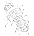
- FIG. 1 is a perspective view showing a filter device according to a first embodiment of the present invention.
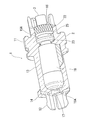
- the perspective view which similarly shows a filter apparatus.
- the figure which shows a filter apparatus with a partial cross section similarly.
- the figure which shows a filter apparatus with a partial cross section similarly.
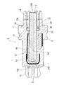
- sectional drawing of a filter apparatus Sectional drawing which similarly shows the usage example of a filter apparatus. Sectional drawing which shows the filter apparatus in 2nd Embodiment of this invention.
- the filter device 1 is provided in a fluid path such as a hydraulic oil path of a lash adjuster in a vehicle engine, and is made of, for example, resin.
- the filter device 1 includes a filter main body 2 and an orifice member 3 assembled to the filter main body 2.
- the filter body 2 includes a large-diameter, generally cylindrical base end portion 11, a small-diameter, generally cylindrical distal end portion 12, and an intermediate portion 13 disposed between the proximal end portion 11 and the distal end portion 12. Yes.
- a flange portion 14 is provided between the distal end portion 12 and the intermediate portion 13.
- the filter main body 2 is formed with a fluid passage 15 extending through the base end portion 11, the intermediate portion 13, and the tip end portion 12 and extending in the longitudinal direction of the filter main body 2.
- the base end portion 11 is a portion constituting the upstream side (fluid introduction side) of the filter device 1, and the introduction port 16 (mounting port of the orifice member 3) of the fluid passage 15 is opened.
- a distal end discharge port 17 of the fluid passage 15 is opened at the distal end portion 12, and the fluid passage 15 extends from the introduction port 16 to the distal end discharge port 17.
- a plurality of side surface discharge ports 18 are formed in the intermediate portion 13, and these side surface discharge ports 18 communicate with the fluid passage 15.
- the base end portion 11 side (introduction port 16) of the filter body 2 is set as the upstream side (fluid introduction side), and the distal end portion 12 side (the tip discharge port 17 and the side surface).
- the discharge port 18) is on the downstream side (fluid discharge side)
- the usage of the filter device 1 is not limited to such a form, and the filter device 1 is connected to the tip portion 12 side (the tip discharge port 17 and the discharge port 18).
- the side discharge port 18) can be used as the upstream side (fluid introduction side), and the base end 11 side (introduction port 16) can be used as the downstream side (fluid discharge side). That is, the expressions “upstream” and “downstream” in this specification are for the convenience of describing the embodiment, and do not limit the scope of rights of the filter device of the present invention.
- the filter main body 2 includes a filter member 19 disposed around the fluid passage 15.
- the filter member 19 is, for example, a metal cylindrical mesh member, and includes a bottom portion 19A only on the distal end side (the distal end discharge port 17 side), and the proximal end side (the introduction port 16 side) is open.
- the fluid for example, hydraulic oil
- the filter member 19 is filtered by the filter member 19, and the distal end outlet 17 And it is discharged from the side discharge port 18.
- the orifice member 3 is a member that is assembled to the filter body 2 by, for example, hot pressing, and is made of, for example, metal. As shown well in FIGS. 4 and 5, the orifice member 3 includes a substantially cylindrical main body 21, a first flange portion 22 provided on the outer periphery near the base end of the main body 21, and a first flange portion 22. And a second flange portion 23 provided at a predetermined interval.
- the first flange portion 22 corresponds to the engaging portion in the claims, and the second flange portion 23 corresponds to the trap portion in the claims.
- An orifice 24 extending through the orifice member 3 in the longitudinal direction is formed on the central axis of the main body 21 of the orifice member 3.
- the first flange portion 22 and the second flange portion 23 have substantially the same outer diameter as the inner diameter of the large-diameter portion 15A on the base end side (inlet port 16 side) of the fluid passage 15.
- a knurl is formed on the outer peripheral surface of the first flange portion 22.
- the second flange portion 23 is disposed on the distal end side (downstream side) of the first flange portion 22 and is in contact with the inner peripheral surface of the large-diameter portion 15A of the fluid passage 15. As a result, a trap space 25 that is a closed space sandwiched between the first flange portion 22 and the second flange portion 23 is formed on the downstream side of the first flange portion 22.
- FIG. 6 shows a usage example of the filter device 1 of the present embodiment.
- the filter device 1 is mounted in the mounting hole 31 of the engine housing 30 from the base end portion 11 side.
- the opening of the attachment hole 31 is closed by the engine cap 40.
- An end portion (oil inlet) of the orifice member 3 of the filter device 1 is disposed in a space 31B formed between the engine cap 40 and the base end portion 11 in the mounting hole 31 and communicates with the oil passage 32.
- the side surface discharge port 18 of the filter device 1 is disposed in a space 31 ⁇ / b> B formed before the base end portion 11 in the attachment hole 31 and communicates with the oil passage 33.
- An O-ring 34 is attached to the outer periphery of the base end portion 11 to provide a seal between the space 31A and the space 31B.
- FIG. 7 shows a filter device 50 according to a second embodiment of the present invention.
- the filter device 50 of the present embodiment instead of the second flange portion 23 of the orifice member 3 in the first embodiment, along the circumferential direction on the inner peripheral surface of the fluid passage 15 (large diameter portion 15A).
- An extending annular portion 27 is provided.
- the other part of the filter apparatus 50 is the same as that of the filter apparatus 1 of the said 1st Embodiment, the same reference number is shown in drawing and description is abbreviate
- the annular portion 27 is used as a trap portion, and a space formed between the annular portion 27 and the first flange portion 22 of the orifice member 3 is formed.
- a trap space 25 may be used.
- the orifice member 3 is hot-pressed into the filter body 2, but the present invention is not limited to such a form.
- the orifice member 3 is cold-pressed into the filter body. May be.
- the present invention can be used for a filter device provided in a hydraulic oil path or the like.
Landscapes
- Chemical & Material Sciences (AREA)
- Chemical Kinetics & Catalysis (AREA)
- Filtration Of Liquid (AREA)
- Pipe Accessories (AREA)
- Fluid-Pressure Circuits (AREA)
- Lubrication Details And Ventilation Of Internal Combustion Engines (AREA)
Abstract
フィルター本体の流体通路にオリフィス部材を組み付けて構成されるフィルター装置において、オリフィス部材の組み付け時に発生する削りカス等の残渣物によって機能が損なわれないようにしたフィルター装置を提供する。フィルター装置1は、流体通路15を有するフィルター本体2と、流体通路15内に組み付けられるオリフィス部材3とを備える。オリフィス部材3は、オリフィス24を有する本体21と、流体通路15の大径部15Aに圧入される第1のフランジ部22と、第1のフランジ部22との間に閉鎖されたトラップ空間25を形成する第2のフランジ部23とを備える。第1のフランジ22の外周面には、ローレットが設けられる。オリフィス部材3のフィルター本体2への組み付け時に生じた削りカスは、トラップ空間25内に捕捉される。
Description
本発明は、流体の濾過に用いられるフィルター装置に関する。
作動油経路等の流体経路における流体の濾過に用いられるフィルター装置においては、濾過機能に加えて、流体を減圧する機能が必要となることがある。この場合、濾過機能を有するフィルター本体の流体通路に、減圧機能を有するオリフィス部材を圧入してフィルター装置を構成することが考えられる。
ところで、このようにオリフィス部材をフィルター本体に圧入する際には残渣物(削りカス)が発生するため、この削りカスがフィルター本体内に残ってフィルター装置の機能を低下させてしまわないようにする必要がある。しかしながら、従来技術には、このような残渣物対策を適切に行うための構成は存在していなかった。
例えば、フィルター装置における異物対策を施した従来技術として、例えば特許文献1(特許第5152005号)には、フィルターが破損したときに、破損によって生じた破片を下流側に流さないようにした発明等は提案がなされている。しかしながら、この構成は、フィルター本体にオリフィス部材を組み込む構成とは無関係のものであるため、フィルター装置の組み立て時に発生する残渣物対策に直接応用できるものではない。
本発明は、以上のような事情を勘案してなされたもので、その目的は、フィルター本体の流体通路にオリフィス部材を組み付けて構成されるフィルター装置において、オリフィス部材の組み付け時に発生する削りカス等の残渣物によって機能が損なわれないようにしたフィルター装置を提供することである。
前記目的を達成するため、本発明にあっては、次のような解決方法を採択している。すなわち、流体通路を有するフィルター本体と、前記フィルター本体の前記流体通路内に組み付けられるオリフィス部材とを備えたフィルター装置において、前記オリフィス部材に、前記流体通路の内周面に係合する係合部を備え、前記フィルター本体と前記オフィス部材のいずれか一方に、前記係合部との間に閉鎖されたトラップ空間を形成するトラップ部を備えた。
上記解決手法によれば、係合部に隣接してトラップ部が設けられ、係合部とトラップ部の間の空間は、閉鎖されたトラップ空間となっているので、フィルター本体へのオリフィス部材の組み付け時(例えば圧入時)に生じた残渣物(例えば削りカス)は、トラップ空間内に捕捉され、トラップ部を越えてフィルター装置内部に入り込んでしまうことはない。したがって、組み付け時の残渣物によるフィルター装置の機能低下(例えば濾過部材の破損やオフィリスの目詰まり)を適切に防止できる。
前記フィルター本体は、前記トラップ部の前記トラップ空間と反対側に配置された濾過
部材を備えていてもよい。この場合、残渣物は、濾過部材に至る前に、トラップ部によって適切に捕捉される。
部材を備えていてもよい。この場合、残渣物は、濾過部材に至る前に、トラップ部によって適切に捕捉される。
前記フィルター本体は、樹脂製であってもよい。また、前記オリフィス部材は、金属製であってもよい。この場合、金属製のオリフィス部材を樹脂製のフィルター本体に組み付けた際に生じる樹脂の削りカスは、トラップ部によってトラップ空間内に適切に捕捉される。
前記係合部は、前記オリフィス部材の外周に設けた第1のフランジ部であり、前記第1のフランジ部が前記流体通路の内周面と係合する部分にローレットを形成してもよい。この場合、オリフィス部材のローレットが、フィルター本体の流体通路の内周面に食い込むことにより、オリフィス部材のフィルター本体の組み付けは容易に行える一方で、ローレットによりフィルター本体が削られた削りカスは、トラップ部によってトラップ空間内に捕捉される。
前記トラップ部は、前記オリフィス部材に設けられた第2のフランジ部であってもよい。この場合、トラップ空間がオリフィス部材に設けた2つのフランジ部の間に形成されるので、簡素な構成で適切なトラップ空間を構成できる。
前記トラップ部は、前記流体通路の内周面に形成された環状部であってもよい。この場合、トラップ空間はオリフィス部材のフランジ部とフィルター本体の環状部の間に形成されるので、簡素な構成で適切なトラップ空間を構成できる。
本発明によれば、オリフィス部材をフィルター本体に組み付けた際に生じる残渣物(例えば削りカス)は、トラップ部によってトラップ空間内に捕捉され、フィルター装置の内部まで入り込んでしまうことはないので、残渣物の侵入によるフィルター装置の破損や機能低下を防止できる。
以下、添付図面に基づいて本発明の実施形態について説明する。
図1から図5には、本発明の第1実施形態におけるフィルター装置1を示す。フィルター装置1は、例えば車両のエンジンにおけるラッシュアジャスタの作動油経路等の流体経
路に設けられるもので、例えば樹脂から形成されている。図示されるように、フィルター装置1は、フィルター本体2と、フィルター本体2に組み付けられるオリフィス部材3から構成されている。
路に設けられるもので、例えば樹脂から形成されている。図示されるように、フィルター装置1は、フィルター本体2と、フィルター本体2に組み付けられるオリフィス部材3から構成されている。
フィルター本体2は、大径の略円筒形状の基端部11と、小径の略円筒形状の先端部12と、基端部11と先端部12の間に配置された中間部13とを備えている。なお、先端部12と中間部13の間には、フランジ部14が設けられている。
図4及び図5によく示されるように、フィルター本体2には、基端部11、中間部13、先端部12を貫いて、フィルター本体2の長手方向に延びる流体通路15が形成されている。基端部11は、フィルター装置1の上流側(流体の導入側)を構成する部分であり、流体通路15の導入口16(オリフィス部材3の装着口)が開口している。一方、先端部12には、流体通路15の先端排出口17が開口しており、流体通路15は、導入口16から先端排出口17に至るまで延びている。さらに、中間部13には、複数の側面排出口18が形成されており、これらの側面排出口18は、流体通路15と連通している。
なお、本実施形態の説明においては、説明の便宜上、フィルター本体2の基端部11側(導入口16)を上流側(流体の導入側)とし、先端部12側(先端排出口17及び側面排出口18)を下流側(流体の排出側)としているが、フィルター装置1の利用法はこのような形態に限られるものでなく、フィルター装置1は、先端部12側(先端排出口17及び側面排出口18)を上流側(流体の導入側)とし、基端部11側(導入口16)を下流側(流体の排出側)として用いることもできる。すなわち、本明細書における上流及び下流との表現は、実施形態を説明するための便宜上のものであって、本発明のフィルター装置の権利範囲を制限するものではない。
図3から図5によく示されるように、フィルター本体2は、流体通路15の周囲に配置された濾過部材19を備えている。濾過部材19は、例えば金属製の円筒形メッシュ部材であり、先端側(先端排出口17側)にのみ底部19Aを備え、基端側(導入口16側)は開口している。これにより、フィルター装置1の導入口16側(オリフィス24の基端側開口24A)から流体通路15内に導入された流体(例えば作動油)は、濾過部材19により濾過されて、先端排出口17及び側面排出口18から排出されるようになっている。
オリフィス部材3は、フィルター本体2に対して、例えば熱圧入によって組み付けられる部材であり、例えば金属から形成されている。図4及び図5によく示されるように、オリフィス部材3は、略円柱形状の本体21と、本体21の基端付近外周に設けられた第1のフランジ部22と、第1のフランジ部22と所定の間隔をもって設けられた第2のフランジ部23を備えている。なお、第1のフランジ部22は、特許請求の範囲における係合部に、第2のフランジ部23は、特許請求の範囲におけるトラップ部に、それぞれ相当する。
オリフィス部材3の本体21の中心軸上には、オリフィス部材3を長手方向に貫通して延びるオリフィス24が形成されている。これにより、オリフィス部材3がフィルター本体2に対して組み付けられた際には、オリフィス24の基端側開口24Aから導入された流体が、オリフィス24を通って減圧されて、オリフィス24の先端側開口24Bから流体通路15内に導入されるようになっている。
第1のフランジ部22及び第2のフランジ部23は、流体通路15の基端側(導入口16側)の大径部15Aの内径と略同一の外径を有している。また、第1のフランジ部22の外周面には、ローレットが形成されている。これにより、オリフィス部材3のフランジ
部22が流体通路15の大径部15Aに対して熱圧入されたときに、フランジ部22のローレットが大径部15Aの内周面に食い込み、オリフィス部材3がフィルター本体2に対して溶着により固定されるようになっている。
部22が流体通路15の大径部15Aに対して熱圧入されたときに、フランジ部22のローレットが大径部15Aの内周面に食い込み、オリフィス部材3がフィルター本体2に対して溶着により固定されるようになっている。
第2のフランジ部23は、第1のフランジ部22よりも先端側(下流側)に配置されており、流体通路15の大径部15Aの内周面に当接した状態となっている。この結果、第1のフランジ部22の下流側には、第1のフランジ部22と第2のフランジ部23の間に挟まれた閉鎖空間であるトラップ空間25が形成される。
このような構成により、第1のフランジ部22を流体通路15の大径部15Aに圧入した際に生じる残渣物(削りカス)26は、フランジ部22の下流側に入ってしまった場合でも、トラップ空間25内に捕捉されるので、第2のフランジ部(トラップ部)23を越えて流体通路15内に侵入してしまうことはない。したがって、組み付け作業時に生じた残渣物によってフィルター装置1の機能が害されてしまうことはない。すなわち、残渣物のフィルター装置1内部への侵入による濾過部材19のメッシュの破損やオリフィス24の目詰まり等が適切に防止される。
図6には、本実施形態のフィルター装置1の使用例を示す。図示されるように、フィルター装置1は、エンジンハウジング30の取り付け穴31に、基端部11側から装着されている。取り付け穴31の開口部は、エンジンキャップ40により閉止されている。フィルター装置1のオリフィス部材3の端部(オイルの導入口)は、取り付け穴31内のエンジンキャップ40と基端部11の間に形成された空間31Bに配置され、オイル通路32に連通している。また、フィルター装置1の側面排出口18は、取り付け穴31内の基端部11よりも先に形成された空間31Bに配置され、オイル通路33に連通している。なお、基端部11の外周にはOリング34が取り付けられ、空間31Aと空間31Bの間のシールがなされている。
図7には、本発明の第2実施形態のフィルター装置50を示す。本実施形態のフィルター装置50においては、上記第1実施形態におけるオリフィス部材3の第2のフランジ部23に代えて、流体通路15(大径部15A)の内周面に、周方向に沿って延びる環状部27が設けられている。なお、フィルター装置50の他の部分は、上記第1の実施形態のフィルター装置1と同様であるので、図面には同一の参照番号を示し、説明を省略する。
このように、フィルター本体2の流体通路15に環状部27を設けることにより、環状部27をトラップ部として、環状部27とオリフィス部材3の第1のフランジ部22の間に形成された空間をトラップ空間25とすることもできる。
以上、本発明の実施形態について説明したが、本発明は、上記実施形態に限定されるものではなく、特許請求の範囲に記載された範囲において適宜の変更が可能である。例えば、上記実施形態では、オリフィス部材3はフィルター本体2に熱圧入されるものとしたが、本発明はこのような形態に限られるものではなく、例えばオリフィス部材3をフィルター本体内に冷間圧入してもよい。
本発明は、作動油経路等に備えられるフィルター装置に利用できる。
1、50 フィルター装置
2 フィルター本体
3 オリフィス部材
11 フィルター本体の基端部
12 フィルター本体の先端部
13 フィルター本体の中間部
14 フィルター本体のフランジ部
15 流体通路
15A 流体通路の大径部
16 導入口
17 先端排出口
18 側面排出口
19 濾過部材
19A 濾過部材の底部
21 オリフィス部材の本体
22 第1のフランジ部
23 第2のフランジ部
24 オリフィス
24A オリフィスの基端側開口
24B オリフィスの先端側開口
25 トラップ空間
26 残渣物(削りカス)
27 環状部
30 エンジンハウジング
31 取り付け穴
32 オイル経路
33 オイル経路
34 Oリング
40 エンジンキャップ
2 フィルター本体
3 オリフィス部材
11 フィルター本体の基端部
12 フィルター本体の先端部
13 フィルター本体の中間部
14 フィルター本体のフランジ部
15 流体通路
15A 流体通路の大径部
16 導入口
17 先端排出口
18 側面排出口
19 濾過部材
19A 濾過部材の底部
21 オリフィス部材の本体
22 第1のフランジ部
23 第2のフランジ部
24 オリフィス
24A オリフィスの基端側開口
24B オリフィスの先端側開口
25 トラップ空間
26 残渣物(削りカス)
27 環状部
30 エンジンハウジング
31 取り付け穴
32 オイル経路
33 オイル経路
34 Oリング
40 エンジンキャップ
Claims (7)
- 流体通路を有するフィルター本体と、前記フィルター本体の前記流体通路内に組み付けられるオリフィス部材とを備えたフィルター装置において、
前記オリフィス部材に、前記流体通路の内周面に係合する係合部を備え、
前記フィルター本体と前記オフィス部材のいずれか一方に、前記係合部との間に閉鎖されたトラップ空間を形成するトラップ部を備えたフィルター装置。 - 請求項1に記載のフィルター装置において、
前記フィルター本体は、前記トラップ部の前記トラップ空間と反対側に配置された濾過部材を備えているフィルター装置。 - 請求項1又は請求項2に記載のフィルター装置において、
前記フィルター本体は、樹脂製であるフィルター装置。 - 請求項1から請求項3のいずれか1項に記載のフィルター装置において、
前記オリフィス部材は、金属製であるフィルター装置。 - 請求項1から請求項4のいずれか1項に記載のフィルター装置において、
前記係合部は、前記オリフィス部材の外周に設けた第1のフランジ部であり、前記第1のフランジ部が前記流体通路の内周面と係合する部分にローレットを形成したフィルター装置。 - 請求項5に記載のフィルター装置において、
前記トラップ部は、前記オリフィス部材に設けられた第2のフランジ部であるフィルター装置。 - 請求項5に記載のフィルター装置において、
前記トラップ部は、前記流体通路の内周面に形成された環状部であるフィルター装置。
Priority Applications (3)
| Application Number | Priority Date | Filing Date | Title |
|---|---|---|---|
| MX2019011099A MX2019011099A (es) | 2017-03-23 | 2018-03-20 | Dispositivo de filtro. |
| CN201880019644.1A CN110461435A (zh) | 2017-03-23 | 2018-03-20 | 过滤装置 |
| US16/494,980 US11752454B2 (en) | 2017-03-23 | 2018-03-20 | Filter device |
Applications Claiming Priority (2)
| Application Number | Priority Date | Filing Date | Title |
|---|---|---|---|
| JP2017-056841 | 2017-03-23 | ||
| JP2017056841A JP6767293B2 (ja) | 2017-03-23 | 2017-03-23 | フィルター装置 |
Publications (1)
| Publication Number | Publication Date |
|---|---|
| WO2018174048A1 true WO2018174048A1 (ja) | 2018-09-27 |
Family
ID=63585415
Family Applications (1)
| Application Number | Title | Priority Date | Filing Date |
|---|---|---|---|
| PCT/JP2018/010986 Ceased WO2018174048A1 (ja) | 2017-03-23 | 2018-03-20 | フィルター装置 |
Country Status (5)
| Country | Link |
|---|---|
| US (1) | US11752454B2 (ja) |
| JP (1) | JP6767293B2 (ja) |
| CN (1) | CN110461435A (ja) |
| MX (1) | MX2019011099A (ja) |
| WO (1) | WO2018174048A1 (ja) |
Families Citing this family (1)
| Publication number | Priority date | Publication date | Assignee | Title |
|---|---|---|---|---|
| CN111991886A (zh) * | 2020-08-28 | 2020-11-27 | 扬州世纪名扬环保科技有限公司 | 一种卧式石材污水处理罐 |
Citations (9)
| Publication number | Priority date | Publication date | Assignee | Title |
|---|---|---|---|---|
| US4312479A (en) * | 1980-02-19 | 1982-01-26 | Stanadyne, Inc. | Fuel injection nozzle with edge filter |
| JPS6247764U (ja) * | 1985-09-11 | 1987-03-24 | ||
| JPH0362287U (ja) * | 1989-10-24 | 1991-06-18 | ||
| US5255794A (en) * | 1991-10-01 | 1993-10-26 | Lucas Industries Public Limited Company | Fuel filter |
| JPH08210211A (ja) * | 1995-02-03 | 1996-08-20 | Nippondenso Co Ltd | 内燃機関用燃料フィルタ装置 |
| US20070209687A1 (en) * | 2006-03-07 | 2007-09-13 | Fistler James D | Automotive glass washer arrangement |
| JP2008080295A (ja) * | 2006-09-28 | 2008-04-10 | Nippon Rokaki Kk | フィルタ装置 |
| JP2008202591A (ja) * | 2007-01-25 | 2008-09-04 | Denso Corp | コモンレール |
| JP2017120030A (ja) * | 2015-12-28 | 2017-07-06 | 株式会社ミクニ | バルブタイミング変更装置 |
Family Cites Families (5)
| Publication number | Priority date | Publication date | Assignee | Title |
|---|---|---|---|---|
| US4270728A (en) * | 1979-09-19 | 1981-06-02 | Eaton Corporation | Block mounted automotive heater control valve |
| CN2388365Y (zh) * | 1999-08-06 | 2000-07-19 | 陆耘 | 新型柴油滤清器 |
| EP1296057B1 (en) * | 2001-09-19 | 2011-01-05 | Filtertek Inc. | Integrated fuel filter and calibration tube for a fuel injector |
| US7603985B2 (en) | 2007-01-25 | 2009-10-20 | Denso Corporation | Common rail |
| JP5152005B2 (ja) | 2009-01-21 | 2013-02-27 | 株式会社デンソー | フィルタ装置および燃料噴射装置 |
-
2017
- 2017-03-23 JP JP2017056841A patent/JP6767293B2/ja active Active
-
2018
- 2018-03-20 US US16/494,980 patent/US11752454B2/en active Active
- 2018-03-20 CN CN201880019644.1A patent/CN110461435A/zh active Pending
- 2018-03-20 MX MX2019011099A patent/MX2019011099A/es unknown
- 2018-03-20 WO PCT/JP2018/010986 patent/WO2018174048A1/ja not_active Ceased
Patent Citations (9)
| Publication number | Priority date | Publication date | Assignee | Title |
|---|---|---|---|---|
| US4312479A (en) * | 1980-02-19 | 1982-01-26 | Stanadyne, Inc. | Fuel injection nozzle with edge filter |
| JPS6247764U (ja) * | 1985-09-11 | 1987-03-24 | ||
| JPH0362287U (ja) * | 1989-10-24 | 1991-06-18 | ||
| US5255794A (en) * | 1991-10-01 | 1993-10-26 | Lucas Industries Public Limited Company | Fuel filter |
| JPH08210211A (ja) * | 1995-02-03 | 1996-08-20 | Nippondenso Co Ltd | 内燃機関用燃料フィルタ装置 |
| US20070209687A1 (en) * | 2006-03-07 | 2007-09-13 | Fistler James D | Automotive glass washer arrangement |
| JP2008080295A (ja) * | 2006-09-28 | 2008-04-10 | Nippon Rokaki Kk | フィルタ装置 |
| JP2008202591A (ja) * | 2007-01-25 | 2008-09-04 | Denso Corp | コモンレール |
| JP2017120030A (ja) * | 2015-12-28 | 2017-07-06 | 株式会社ミクニ | バルブタイミング変更装置 |
Also Published As
| Publication number | Publication date |
|---|---|
| US11752454B2 (en) | 2023-09-12 |
| CN110461435A (zh) | 2019-11-15 |
| US20200197839A1 (en) | 2020-06-25 |
| JP2018158295A (ja) | 2018-10-11 |
| JP6767293B2 (ja) | 2020-10-14 |
| MX2019011099A (es) | 2020-02-05 |
Similar Documents
| Publication | Publication Date | Title |
|---|---|---|
| US10137390B2 (en) | Filter device, especially liquid filter | |
| EP3659692B1 (de) | Gehäuse, gehäusedeckel und verbindungsteil einer einrichtung zur abscheidung wenigstens eines fluids aus gas und einrichtung zur abscheidung eines fluids | |
| EP1451464B1 (de) | Ansaugluftfilter für eine brennkraftmaschine | |
| JP2005520962A (ja) | オイルフィルタ装置 | |
| US6224758B1 (en) | Filter assembly | |
| CN105683558A (zh) | 用于流体喷射阀的过滤器、流体喷射阀、及用于制造流体喷射阀的过滤器的方法 | |
| US20150246303A1 (en) | Replaceable Oil Filter Sub-Assembly | |
| US7392783B2 (en) | Internal combustion engine, especially in a motor vehicle, having a fuel filter system | |
| WO2018174048A1 (ja) | フィルター装置 | |
| CA2393032C (en) | Combination valve support and sealing element for filter cartridges | |
| US5679244A (en) | Spin-on liquid filter with unique straight through flow path | |
| US5980618A (en) | Air filter with failsafe filtered pressure tap | |
| US20200384391A1 (en) | Filter Element of a Filter for Liquid, Drain Closure Element for a Drain Opening in a Filter Housing, Housing Part of a Filter Housing and Filter | |
| JP7714053B2 (ja) | フィルタを統合したインジェクタ | |
| CN111386145A (zh) | 用于液体的过滤器的过滤元件、过滤器和过滤器壳体 | |
| CN104623949A (zh) | 滤芯和过滤器单元 | |
| US20050242012A1 (en) | One-piece anti-drain back valve allowing relief valve flow | |
| US5938924A (en) | Filter | |
| JP2010209705A (ja) | オイルストレーナ | |
| EP0137275B1 (en) | Flow control valve | |
| CN114650873A (zh) | 过滤器脉动抑制装置 | |
| EP4342560A1 (en) | Gas filter system | |
| JP4407909B2 (ja) | ガス分析装置用フィルタ | |
| JP2567574B2 (ja) | フィルタ装置 | |
| EP4058174B1 (en) | Filter dampening device for pressure pulsation |
Legal Events
| Date | Code | Title | Description |
|---|---|---|---|
| 121 | Ep: the epo has been informed by wipo that ep was designated in this application |
Ref document number: 18770697 Country of ref document: EP Kind code of ref document: A1 |
|
| NENP | Non-entry into the national phase |
Ref country code: DE |
|
| 122 | Ep: pct application non-entry in european phase |
Ref document number: 18770697 Country of ref document: EP Kind code of ref document: A1 |