WO2018173783A1 - 永久磁石、回転電機、及び車両 - Google Patents
永久磁石、回転電機、及び車両 Download PDFInfo
- Publication number
- WO2018173783A1 WO2018173783A1 PCT/JP2018/009080 JP2018009080W WO2018173783A1 WO 2018173783 A1 WO2018173783 A1 WO 2018173783A1 JP 2018009080 W JP2018009080 W JP 2018009080W WO 2018173783 A1 WO2018173783 A1 WO 2018173783A1
- Authority
- WO
- WIPO (PCT)
- Prior art keywords
- permanent magnet
- phase
- less
- atomic
- rotating electrical
- Prior art date
- Legal status (The legal status is an assumption and is not a legal conclusion. Google has not performed a legal analysis and makes no representation as to the accuracy of the status listed.)
- Ceased
Links
Images


Classifications
-
- H—ELECTRICITY
- H02—GENERATION; CONVERSION OR DISTRIBUTION OF ELECTRIC POWER
- H02K—DYNAMO-ELECTRIC MACHINES
- H02K1/00—Details of the magnetic circuit
- H02K1/02—Details of the magnetic circuit characterised by the magnetic material
-
- H—ELECTRICITY
- H01—ELECTRIC ELEMENTS
- H01F—MAGNETS; INDUCTANCES; TRANSFORMERS; SELECTION OF MATERIALS FOR THEIR MAGNETIC PROPERTIES
- H01F1/00—Magnets or magnetic bodies characterised by the magnetic materials therefor; Selection of materials for their magnetic properties
- H01F1/01—Magnets or magnetic bodies characterised by the magnetic materials therefor; Selection of materials for their magnetic properties of inorganic materials
- H01F1/03—Magnets or magnetic bodies characterised by the magnetic materials therefor; Selection of materials for their magnetic properties of inorganic materials characterised by their coercivity
- H01F1/032—Magnets or magnetic bodies characterised by the magnetic materials therefor; Selection of materials for their magnetic properties of inorganic materials characterised by their coercivity of hard-magnetic materials
- H01F1/04—Magnets or magnetic bodies characterised by the magnetic materials therefor; Selection of materials for their magnetic properties of inorganic materials characterised by their coercivity of hard-magnetic materials metals or alloys
- H01F1/047—Alloys characterised by their composition
- H01F1/053—Alloys characterised by their composition containing rare earth metals
- H01F1/055—Alloys characterised by their composition containing rare earth metals and magnetic transition metals, e.g. SmCo5
- H01F1/059—Alloys characterised by their composition containing rare earth metals and magnetic transition metals, e.g. SmCo5 and Va elements, e.g. Sm2Fe17N2
- H01F1/0596—Alloys characterised by their composition containing rare earth metals and magnetic transition metals, e.g. SmCo5 and Va elements, e.g. Sm2Fe17N2 of rhombic or rhombohedral Th2Zn17 structure or hexagonal Th2Ni17 structure
-
- B—PERFORMING OPERATIONS; TRANSPORTING
- B22—CASTING; POWDER METALLURGY
- B22F—WORKING METALLIC POWDER; MANUFACTURE OF ARTICLES FROM METALLIC POWDER; MAKING METALLIC POWDER; APPARATUS OR DEVICES SPECIALLY ADAPTED FOR METALLIC POWDER
- B22F1/00—Metallic powder; Treatment of metallic powder, e.g. to facilitate working or to improve properties
- B22F1/10—Metallic powder containing lubricating or binding agents; Metallic powder containing organic material
-
- C—CHEMISTRY; METALLURGY
- C22—METALLURGY; FERROUS OR NON-FERROUS ALLOYS; TREATMENT OF ALLOYS OR NON-FERROUS METALS
- C22C—ALLOYS
- C22C38/00—Ferrous alloys, e.g. steel alloys
- C22C38/001—Ferrous alloys, e.g. steel alloys containing N
-
- C—CHEMISTRY; METALLURGY
- C22—METALLURGY; FERROUS OR NON-FERROUS ALLOYS; TREATMENT OF ALLOYS OR NON-FERROUS METALS
- C22C—ALLOYS
- C22C38/00—Ferrous alloys, e.g. steel alloys
- C22C38/005—Ferrous alloys, e.g. steel alloys containing rare earths, i.e. Sc, Y, Lanthanides
-
- C—CHEMISTRY; METALLURGY
- C22—METALLURGY; FERROUS OR NON-FERROUS ALLOYS; TREATMENT OF ALLOYS OR NON-FERROUS METALS
- C22C—ALLOYS
- C22C38/00—Ferrous alloys, e.g. steel alloys
- C22C38/02—Ferrous alloys, e.g. steel alloys containing silicon
-
- C—CHEMISTRY; METALLURGY
- C22—METALLURGY; FERROUS OR NON-FERROUS ALLOYS; TREATMENT OF ALLOYS OR NON-FERROUS METALS
- C22C—ALLOYS
- C22C38/00—Ferrous alloys, e.g. steel alloys
- C22C38/18—Ferrous alloys, e.g. steel alloys containing chromium
-
- H—ELECTRICITY
- H01—ELECTRIC ELEMENTS
- H01F—MAGNETS; INDUCTANCES; TRANSFORMERS; SELECTION OF MATERIALS FOR THEIR MAGNETIC PROPERTIES
- H01F1/00—Magnets or magnetic bodies characterised by the magnetic materials therefor; Selection of materials for their magnetic properties
- H01F1/01—Magnets or magnetic bodies characterised by the magnetic materials therefor; Selection of materials for their magnetic properties of inorganic materials
- H01F1/03—Magnets or magnetic bodies characterised by the magnetic materials therefor; Selection of materials for their magnetic properties of inorganic materials characterised by their coercivity
- H01F1/032—Magnets or magnetic bodies characterised by the magnetic materials therefor; Selection of materials for their magnetic properties of inorganic materials characterised by their coercivity of hard-magnetic materials
- H01F1/04—Magnets or magnetic bodies characterised by the magnetic materials therefor; Selection of materials for their magnetic properties of inorganic materials characterised by their coercivity of hard-magnetic materials metals or alloys
- H01F1/047—Alloys characterised by their composition
-
- H—ELECTRICITY
- H01—ELECTRIC ELEMENTS
- H01F—MAGNETS; INDUCTANCES; TRANSFORMERS; SELECTION OF MATERIALS FOR THEIR MAGNETIC PROPERTIES
- H01F1/00—Magnets or magnetic bodies characterised by the magnetic materials therefor; Selection of materials for their magnetic properties
- H01F1/01—Magnets or magnetic bodies characterised by the magnetic materials therefor; Selection of materials for their magnetic properties of inorganic materials
- H01F1/03—Magnets or magnetic bodies characterised by the magnetic materials therefor; Selection of materials for their magnetic properties of inorganic materials characterised by their coercivity
- H01F1/032—Magnets or magnetic bodies characterised by the magnetic materials therefor; Selection of materials for their magnetic properties of inorganic materials characterised by their coercivity of hard-magnetic materials
- H01F1/04—Magnets or magnetic bodies characterised by the magnetic materials therefor; Selection of materials for their magnetic properties of inorganic materials characterised by their coercivity of hard-magnetic materials metals or alloys
- H01F1/047—Alloys characterised by their composition
- H01F1/053—Alloys characterised by their composition containing rare earth metals
- H01F1/055—Alloys characterised by their composition containing rare earth metals and magnetic transition metals, e.g. SmCo5
- H01F1/0555—Alloys characterised by their composition containing rare earth metals and magnetic transition metals, e.g. SmCo5 pressed, sintered or bonded together
- H01F1/0558—Alloys characterised by their composition containing rare earth metals and magnetic transition metals, e.g. SmCo5 pressed, sintered or bonded together bonded together
-
- H—ELECTRICITY
- H01—ELECTRIC ELEMENTS
- H01F—MAGNETS; INDUCTANCES; TRANSFORMERS; SELECTION OF MATERIALS FOR THEIR MAGNETIC PROPERTIES
- H01F1/00—Magnets or magnetic bodies characterised by the magnetic materials therefor; Selection of materials for their magnetic properties
- H01F1/01—Magnets or magnetic bodies characterised by the magnetic materials therefor; Selection of materials for their magnetic properties of inorganic materials
- H01F1/03—Magnets or magnetic bodies characterised by the magnetic materials therefor; Selection of materials for their magnetic properties of inorganic materials characterised by their coercivity
- H01F1/032—Magnets or magnetic bodies characterised by the magnetic materials therefor; Selection of materials for their magnetic properties of inorganic materials characterised by their coercivity of hard-magnetic materials
- H01F1/04—Magnets or magnetic bodies characterised by the magnetic materials therefor; Selection of materials for their magnetic properties of inorganic materials characterised by their coercivity of hard-magnetic materials metals or alloys
- H01F1/047—Alloys characterised by their composition
- H01F1/053—Alloys characterised by their composition containing rare earth metals
- H01F1/055—Alloys characterised by their composition containing rare earth metals and magnetic transition metals, e.g. SmCo5
- H01F1/059—Alloys characterised by their composition containing rare earth metals and magnetic transition metals, e.g. SmCo5 and Va elements, e.g. Sm2Fe17N2
-
- H—ELECTRICITY
- H01—ELECTRIC ELEMENTS
- H01F—MAGNETS; INDUCTANCES; TRANSFORMERS; SELECTION OF MATERIALS FOR THEIR MAGNETIC PROPERTIES
- H01F41/00—Apparatus or processes specially adapted for manufacturing or assembling magnets, inductances or transformers; Apparatus or processes specially adapted for manufacturing materials characterised by their magnetic properties
- H01F41/02—Apparatus or processes specially adapted for manufacturing or assembling magnets, inductances or transformers; Apparatus or processes specially adapted for manufacturing materials characterised by their magnetic properties for manufacturing cores, coils, or magnets
- H01F41/0206—Manufacturing of magnetic cores by mechanical means
- H01F41/0246—Manufacturing of magnetic circuits by moulding or by pressing powder
-
- H—ELECTRICITY
- H01—ELECTRIC ELEMENTS
- H01F—MAGNETS; INDUCTANCES; TRANSFORMERS; SELECTION OF MATERIALS FOR THEIR MAGNETIC PROPERTIES
- H01F7/00—Magnets
- H01F7/02—Permanent magnets [PM]
- H01F7/0231—Magnetic circuits with PM for power or force generation
-
- B—PERFORMING OPERATIONS; TRANSPORTING
- B22—CASTING; POWDER METALLURGY
- B22F—WORKING METALLIC POWDER; MANUFACTURE OF ARTICLES FROM METALLIC POWDER; MAKING METALLIC POWDER; APPARATUS OR DEVICES SPECIALLY ADAPTED FOR METALLIC POWDER
- B22F2304/00—Physical aspects of the powder
- B22F2304/10—Micron size particles, i.e. above 1 micrometer up to 500 micrometer
-
- B—PERFORMING OPERATIONS; TRANSPORTING
- B22—CASTING; POWDER METALLURGY
- B22F—WORKING METALLIC POWDER; MANUFACTURE OF ARTICLES FROM METALLIC POWDER; MAKING METALLIC POWDER; APPARATUS OR DEVICES SPECIALLY ADAPTED FOR METALLIC POWDER
- B22F3/00—Manufacture of workpieces or articles from metallic powder characterised by the manner of compacting or sintering; Apparatus specially adapted therefor ; Presses and furnaces
- B22F3/12—Both compacting and sintering
- B22F3/16—Both compacting and sintering in successive or repeated steps
-
- B—PERFORMING OPERATIONS; TRANSPORTING
- B22—CASTING; POWDER METALLURGY
- B22F—WORKING METALLIC POWDER; MANUFACTURE OF ARTICLES FROM METALLIC POWDER; MAKING METALLIC POWDER; APPARATUS OR DEVICES SPECIALLY ADAPTED FOR METALLIC POWDER
- B22F9/00—Making metallic powder or suspensions thereof
- B22F9/02—Making metallic powder or suspensions thereof using physical processes
- B22F9/04—Making metallic powder or suspensions thereof using physical processes starting from solid material, e.g. by crushing, grinding or milling
-
- B—PERFORMING OPERATIONS; TRANSPORTING
- B22—CASTING; POWDER METALLURGY
- B22F—WORKING METALLIC POWDER; MANUFACTURE OF ARTICLES FROM METALLIC POWDER; MAKING METALLIC POWDER; APPARATUS OR DEVICES SPECIALLY ADAPTED FOR METALLIC POWDER
- B22F9/00—Making metallic powder or suspensions thereof
- B22F9/16—Making metallic powder or suspensions thereof using chemical processes
-
- C—CHEMISTRY; METALLURGY
- C22—METALLURGY; FERROUS OR NON-FERROUS ALLOYS; TREATMENT OF ALLOYS OR NON-FERROUS METALS
- C22C—ALLOYS
- C22C2202/00—Physical properties
- C22C2202/02—Magnetic
-
- H—ELECTRICITY
- H02—GENERATION; CONVERSION OR DISTRIBUTION OF ELECTRIC POWER
- H02K—DYNAMO-ELECTRIC MACHINES
- H02K2213/00—Specific aspects, not otherwise provided for and not covered by codes H02K2201/00 - H02K2211/00
- H02K2213/03—Machines characterised by numerical values, ranges, mathematical expressions or similar information
Definitions
- Embodiment relates to a permanent magnet, a rotating electrical machine, and a vehicle.
- rare earth magnets such as Sm—Co magnets and Nd—Fe—B magnets are known. Rare earth magnets are used in electric devices such as motors, speakers, and measuring instruments, and also in vehicles such as hybrid electric vehicles (HEV) and electric vehicles (EV).
- HEV hybrid electric vehicles
- EV electric vehicles
- BH max maximum magnetic energy product
- a magnet material for obtaining a higher performance permanent magnet for example, a combination of a rare earth element and a transition metal element such as Fe is promising.
- Sm-Fe-N-based materials have high saturation magnetization comparable to Nd-Fe-B-based materials and large magnetic anisotropy exceeding that of Nd-Fe-B-based materials. Has been.
- the Sm—Fe—N based magnet material has a drawback that it is thermally decomposed by heating at a temperature of about 550 ° C. or higher, applying a densification process by sintering to obtain a high density results in Sm
- the —Fe—N magnet material is thermally decomposed, and the ⁇ -Fe phase is precipitated.
- the problem to be solved by the embodiment is to suppress a decrease in the coercive force of the permanent magnet.
- the permanent magnet of the embodiment has a composition formula: RM Z N X (where R is at least one element selected from the group consisting of rare earth elements, Zr, Nb, and Hf, and M is at least one selected from the group consisting of Fe and Co).
- R is at least one element selected from the group consisting of rare earth elements, Zr, Nb, and Hf
- M is at least one selected from the group consisting of Fe and Co.
- X is an atomic ratio satisfying 0.5 ⁇ X ⁇ 2.0
- Z is an atomic ratio satisfying 4 ⁇ Z ⁇ 13
- Th 2 Ni 17 type Th 2 Zn 17 type
- a main phase having at least one crystal structure selected from TbCu 7 type, and a subphase including an oxide phase and an ⁇ -Fe phase.
- the volume ratio of the oxide phase to the total amount of the main phase and the subphase is 3% or more and 8% or less.
- the specific surface area of the ⁇ -Fe phase is 5 ⁇ m ⁇ 1 or less.
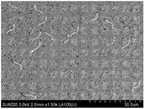
- FIG. 1 is a diagram illustrating an example of an SEM (Scanning Electron Microscope) observation image of a cross section of a permanent magnet.
- the structure shown in FIG. 1 has a main phase 1 and a subphase including an oxide phase 2 and an ⁇ -Fe phase 3.
- the main phase 1 is the phase with the highest volume occupancy among the crystalline and amorphous phases in the permanent magnet.
- the oxide phase 2 is a phase having a lower volume occupancy than the main phase 1.
- the oxide phase 2 has a crystal phase different from the main phase 1 or an amorphous phase.
- the ⁇ -Fe phase 3 is a different phase from the oxide phase 2.
- composition of the permanent magnet of the embodiment is represented by the following composition formula (1).
- RM Z N X (1) (Wherein R is at least one element selected from the group consisting of rare earth elements, Zr, Nb, and Hf, M is at least one element selected from the group consisting of Fe and Co, and X is 0.5 ⁇ X ⁇ 2 0.0 is an atomic ratio satisfying 0.0, and Z is an atomic ratio satisfying 4 ⁇ Z ⁇ 13.)
- R is at least one element selected from rare earth elements, zirconium (Zr), niobium (Nb), and hafnium (Hf).
- rare earth elements include yttrium (Y), lanthanum (La), cerium (Ce), praseodymium (Pr), neodymium (Nd), and samarium (Sm).
- Y yttrium
- La lanthanum
- Ce cerium
- Pr praseodymium
- Nd neodymium
- Sm samarium
- R one type of element may be used, or a plurality of types of elements may be used.
- R imparts a large magnetic anisotropy and a high coercive force to the magnet. It is preferable that 50 atomic% or more of R is Sm. It is desirable that 70 atom% or more of R is Sm.
- Nitrogen (N) is present in the crystal lattice of the main phase 1 and the subphase.
- nitrogen is contained in the crystal lattice, the crystal lattice expands and the electronic structure changes. Thereby, the Curie temperature, magnetic anisotropy, and saturation magnetization of the permanent magnet are improved.
- the atomic ratio of nitrogen is 0.5 or more and 2.0 or less when R is 1. That is, X is an atomic ratio that satisfies 0.5 ⁇ X ⁇ 2.0. X is more preferably an atomic ratio satisfying 1.0 ⁇ X ⁇ 1.5. When X is less than 0.5, the effect of containing nitrogen in the permanent magnet cannot be sufficiently obtained. When X exceeds 2.0, the saturation magnetization of the permanent magnet is lowered.
- a part of N may be substituted with at least one element selected from hydrogen (H), boron (B), and carbon (C).
- the substitution element one kind of element or a plurality of kinds of elements may be used.
- the substitution element exhibits the same effect as nitrogen described above. However, excessive substitution of nitrogen causes a decrease in the magnetic anisotropy of the permanent magnet. Therefore, it is preferable that 50 atomic% or less of nitrogen is substituted with the above element.
- M is at least one element selected from iron (Fe) and cobalt (Co).
- Fe iron
- Co cobalt
- M one type of element may be used, or a plurality of types of elements may be used.
- M is an element mainly responsible for the magnetization of the permanent magnet. By containing M in a relatively large amount, the saturation magnetization of the permanent magnet can be increased. However, when the content of M becomes excessive, the ⁇ -Fe phase and the like are precipitated and the coercive force is lowered.
- M is Fe.
- 70 atomic% or more of M is more preferably Fe.
- Fe in M contributes particularly to the improvement of the magnetization of the permanent magnet.
- the permanent magnet contains Co as a part of M, the Curie temperature of the permanent magnet is increased, and the thermal stability of the permanent magnet is improved. Moreover, the coercive force of the permanent magnet is also increased.
- Part of M is titanium (Ti), vanadium (V), tantalum (Ta), molybdenum (Mo), tungsten (W), manganese (Mn), nickel (Ni), zinc (Zn), and germanium (Ge) It may be substituted with at least one element selected from.
- a substitution element one type of element may be used or a plurality of types of elements may be used.
- An element substituting for a part of M contributes to improvement of magnetic properties, for example, coercive force. However, if a part of M is replaced too much, the magnetization of the permanent magnet decreases. Therefore, it is preferable that 20 atomic% or less of M, and further 10 atomic% or less of M is substituted with the above element.
- a part of M may be substituted with at least one element selected from the group consisting of chromium (Cr) and silicon (Si).
- Cr and Si increase the thermal decomposition temperature of the RMN permanent magnet.
- Cr or Si mainly replaces sites occupied by M in the main phase.
- Cr can improve the thermal stability of the crystal by changing the number of d electrons in the crystal.
- Si can increase the thermal stability of the crystal by reducing the size of the crystal lattice.
- Cr and Si By including Cr and Si in the permanent magnet, thermal decomposition of the RMN permanent magnet in the sintering process can be suppressed, and precipitation of the ⁇ -Fe phase can be suppressed. It is preferable that 20 atom% or less of M, more preferably 10 atom% or less of M is substituted with the above element.
- the main phase 1 has at least one crystal structure selected from Th 2 Ni 17 type, Th 2 Zn 17 type, and TbCu 7 type.
- the main phase 1 has an RMN phase such as Sm 2 (Fe, Cr, Si) 17 N 3 phase.
- Examples of the oxide phase 2 include an R oxide phase. If the oxide phase 2 in the permanent magnet is present in a large amount, the saturation magnetization of the permanent magnet is lowered. In addition, if the ⁇ -Fe phase 3 is present in the permanent magnet, magnetization reversal nuclei are likely to be generated in the vicinity of the interface with the main phase, which causes a reduction in the coercive force of the permanent magnet. Even when the volume ratio of the ⁇ -Fe phase 3 in the permanent magnet is the same, the specific surface area increases as the shape of the ⁇ -Fe phase 3 becomes needle-like, and the contact interface with the main phase increases. It tends to decrease.
- the shape of the ⁇ -Fe phase 3 generated by thermal decomposition during sintering becomes granular.
- the specific surface area of the ⁇ -Fe phase 3 can be reduced.
- the specific surface area of the ⁇ -Fe phase 3 is preferably 5 ⁇ m ⁇ 1 or less.
- the specific surface area of the ⁇ -Fe phase 3 may be defined by, for example, the surface area per unit volume of the ⁇ -Fe phase 3. The specific surface area becomes the minimum value when the crystal particles are spherical. Therefore, the lower limit of the specific surface area is uniquely determined.
- the volume ratio of the total amount of the oxide phase 2 is preferably 8% or less, but in order to obtain the effect of reducing the specific surface area of the ⁇ -Fe phase 3 due to the presence of the oxide phase 2.
- the volume ratio of the total amount of the oxide phase 2 is preferably 3% or more.
- the volume ratio of the total amount of ⁇ -Fe phase 3 in the permanent magnet is preferably 5% or less.
- the analysis of the composition of the permanent magnet is performed by, for example, inductively coupled plasma (ICP) emission spectroscopy.
- ICP inductively coupled plasma
- a powder alloy powder in which the magnet is pulverized with a jet mill, a ball mill, or the like, and a powder having a particle size of 10 ⁇ m or more is 3% by volume or less is used. Samples are taken 10 times at random from the obtained powder, and the sample is analyzed. The average value obtained by subtracting the maximum value and the minimum value from the analyzed measured value is taken as the composition of the permanent magnet.
- the main phase 1, the oxide phase 2, and the ⁇ -Fe phase 3 may be, for example, SEM-EDX (Scanning Electron Microscope-Energy Dispersive X-ray Spectroscopy), TEM-EDX (Transmission Electro-Semi-ElectroDemi-S-ElectroXe-M-D It can be specified by the method. According to TEM-EDX, an electron beam is focused on a main phase part, a grain boundary phase part, etc., and the constituent element ratio of each part can be quantified, and the crystal structure can be identified.
- SEM-EDX Sccanning Electron Microscope-Energy Dispersive X-ray Spectroscopy
- TEM-EDX Transmission Electro-Semi-ElectroDemi-S-ElectroXe-M-D It can be specified by the method. According to TEM-EDX, an electron beam is focused on a main phase part, a grain boundary phase part, etc., and the constituent element ratio
- a method for identifying the main phase 1, the oxide phase 2, and the ⁇ -Fe phase 3 using SEM-EDX will be described below.
- An SEM image having an observation area of 50 ⁇ m ⁇ 50 ⁇ m is acquired.
- the continuous region where the O element concentration is 40 atomic% is the oxide phase 2
- the continuous region where the O element concentration is less than 40 atomic percent and the R element concentration is 10 atomic percent or more is the main phase 1
- the O element A continuous region in which the concentration of Al is less than 40 atomic%, the R element concentration is less than 10 atomic%, and the Fe concentration is 90 atomic% or more is defined as ⁇ -Fe phase 3, respectively.
- the area ratio between the main phase 1 and ⁇ -Fe phase 3 and the oxide phase 2 defined as described above is calculated as the volume ratio, and is defined as the volume ratio of the oxide phase in the permanent magnet.
- a value obtained by directly calculating the area ratio of the main phase 1 / oxide phase 2 and the ⁇ -Fe phase 3 as a volume ratio is defined as the volume ratio of the ⁇ -Fe phase in the permanent magnet.
- the volume ratio of the oxide phase and the volume ratio of the ⁇ -Fe phase 3 were calculated by the method described above in five observation fields, respectively, and the averaged values were calculated for the oxide phase of the permanent magnet.
- the volume ratio is defined as the volume ratio of ⁇ -Fe phase 3.
- the long axis may be defined by the longest straight line (first straight line) when a straight line connecting two points on the periphery of the continuous region is drawn.
- the short axis may be defined by, for example, a longest straight line (second straight line) when a straight line that is perpendicular to the first straight line and connects two points on the periphery of the continuous region is drawn.
- the specific surface area was calculated for all the continuous regions defined as the ⁇ -Fe phase within the same observation field for the five observation fields, and the average was calculated as the ratio of the ⁇ -Fe phase of the permanent magnet. Defined as surface area.
- the permanent magnet of the embodiment can improve the density of the permanent magnet without reducing the coercive force by reducing the specific surface area of the ⁇ -Fe phase having low thermal stability.
- the permanent magnet of the embodiment has a density of 6.5 g / cm 3 or more.
- the density of the permanent magnet is calculated by the Archimedes method by measuring the mass of the permanent magnet in the air and in water. At this time, each sample is calculated 10 times, and the average value excluding the maximum value and the minimum value among the obtained density of the permanent magnet is defined as the density of the permanent magnet.
- an alloy powder containing a predetermined amount of element is prepared.
- the alloy powder is represented by the composition formula (2).
- the alloy powder may contain at least one element selected from the group consisting of hydrogen, boron, and carbon.
- the atomic ratio Z indicating the ratio of the total content of M other than R is a number satisfying 4 ⁇ Z ⁇ 13.
- the alloy powder is prepared by, for example, grinding an alloy ingot obtained by casting a molten metal by an arc melting method or a high frequency melting method, or an alloy ribbon produced by a molten metal quenching method.
- Other preparation methods of the alloy powder include mechanical alloying method, mechanical grinding method, gas atomization method, reduction diffusion method and the like.
- the alloy powder or the alloy before pulverization may be homogenized by heat treatment as necessary.
- the pulverization of the alloy ingot or the alloy ribbon is preferably performed so that the particle size of the alloy powder is 45 ⁇ m or less.
- the particle diameter of the alloy powder is 45 ⁇ m or less, nitrogen can be sufficiently infiltrated into the inside of the particle, and the entire particle can be uniformly nitrided.
- the pulverization of the alloy ingot, the alloy ribbon, or the like is performed using, for example, a jet mill or a ball mill.
- the alloy ingot, the alloy ribbon, and the like are preferably pulverized in an inert gas atmosphere or the like.
- the alloy powder is subjected to nitriding treatment.
- heat treatment is performed at a temperature of 300 to 900 ° C. for 0.1 to 100 hours in a nitrogen gas atmosphere of 0.1 to 100 atm.
- a nitrogen gas atmosphere pressure of 0.5 to 10 atm and a temperature of 450 to 750 ° C. for 2 to 24 hours.
- the atmosphere during the nitriding treatment of the alloy powder may be nitrogen compound gas such as ammonia instead of nitrogen gas.
- the nitriding reaction can also be controlled by using a gas in which nitrogen gas or nitrogen compound gas and hydrogen are mixed.
- the alloy powder before nitriding treatment may contain carbon or boron, or carbon or boron may be contained using a carbon compound gas or boron compound gas. May be.
- An organic compound containing oxygen atoms is added to the nitriding alloy powder.
- the organic compound containing an oxygen atom for example, fatty acids such as stearic acid and oleic acid can be used. Since fatty acids have hydroxyl groups and are poorly volatile, they protect the powder surface until the subsequent sintering step to prevent performance degradation due to surface oxidation and the like, and generally higher fatty acids volatilize or thermally decompose when heated to about 400 ° C. Therefore, in the sintering process, it efficiently functions as a supply source of oxygen atoms that oxidize the powder surface uniformly and appropriately. From the above characteristics, it can be said that fatty acids are suitable as an organic compound to be added when producing a permanent magnet.
- the organic compound is added by a method such as kneading with nitride alloy powder using a mixer, adding as a dispersant to a ball mill, or adding as a coating agent to a jet mill.
- a method such as kneading with nitride alloy powder using a mixer, adding as a dispersant to a ball mill, or adding as a coating agent to a jet mill.
- covered on the nitride alloy powder surface can be obtained.
- the amount of fatty acid to be added is too small, the effect of coating cannot be sufficiently obtained, and if it is too large, the thickness of the coating, that is, the volume ratio of the coated portion is increased and the magnetization of the permanent magnet is lowered.
- the amount of fatty acid to be added is preferably 0.01% or more and 10% or less by weight with respect to the nitride alloy powder.
- the powder (nitrided alloy powder) is filled in a mold placed in an electromagnet, and pressure compaction is performed while applying a magnetic field to produce a green compact with crystal axes oriented.
- the green compact is sintered.
- a sintering method it is preferable to use a discharge plasma sintering method.
- spark plasma sintering it is considered that current tends to flow selectively on the surface of powder particles, which is suitable for increasing the density of permanent magnets while suppressing the thermal load on the RMN phase. Yes.
- Sintering is preferably performed in a vacuum atmosphere or an inert gas atmosphere such as argon gas.
- the spark plasma sintering is performed at a temperature higher than the boiling point or decomposition temperature of the added organic compound.
- the sintering temperature is 400 to 700 ° C.
- a dense permanent magnet can be obtained. If it is less than 400 degreeC, a permanent magnet with sufficient density cannot be obtained. If the temperature exceeds 700 ° C., thermal decomposition of the permanent magnet proceeds, and an ⁇ -Fe phase or the like is generated in the permanent magnet, so that the magnetic properties of the permanent magnet are significantly deteriorated.
- a permanent magnet can be obtained by the above process.
- the magnetic properties of the obtained permanent magnet can be measured with a vibrating sample magnetometer.
- the residual magnetization can be measured as follows. An external magnetic field is applied up to +1600 kA / m in a direction parallel to the magnetization direction oriented before sintering, the magnetic field is returned to zero, and the value of magnetization measured at that time is defined as the residual magnetization of the permanent magnet.
- the same measurement is performed for a nickel standard sample (a sample whose absolute value of magnetization is known) similar to the sample to be measured, and the absolute value of magnetization is calibrated.
- the surface of the nitride alloy powder is reacted with the oxygen atoms contained in the organic compound by setting the temperature higher than the boiling point or decomposition temperature of the organic compound added to the nitride alloy powder during sintering. And a fine oxide phase is formed on the surface of the nitride alloy powder.
- the presence of this minute oxide phase blocks the continuous formation of the ⁇ -Fe phase generated between the crystal grains due to thermal decomposition of the RMN phase during sintering, and the ⁇ -Fe phase.
- the specific surface area is reduced. As a result, as described above, it is possible to suppress a decrease in the coercive force of the permanent magnet due to the generation of the ⁇ -Fe phase.
- the permanent magnet of the first embodiment can be used for a rotating electrical machine, for example, a motor or a generator.
- These rotating electrical machines are composed of at least a stator (stator) and a rotor (rotor).
- FIG. 2 is a diagram illustrating a configuration example of a permanent magnet motor that is a rotating electrical machine using the permanent magnet of the embodiment.
- the permanent magnet motor 21 includes a stator (stator) 22 and a rotor (rotor) 23.
- a rotor 23 is disposed in the stator 22.
- the stator 22 rotates the rotor 23.
- the rotor 23 includes an iron core 24 and the permanent magnet 25 of the embodiment. Based on the characteristics of the permanent magnet 25 and the like, the permanent magnet motor 21 can be improved in efficiency, size, cost, and the like.
- the permanent magnet motor 21 is suitable for a motor for a vehicle such as a hybrid vehicle or an electric vehicle that requires high motor output and miniaturization of the motor.
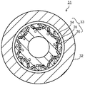
- FIG. 3 is a diagram showing a configuration example of a variable magnetic flux motor that is a rotating electrical machine.
- the variable magnetic flux motor 31 includes a stator 32 and a rotor 33.
- a rotor 33 is disposed in the stator 32.
- the rotor 33 includes an iron core 34, a fixed magnet 35, and a variable magnet 36.
- the permanent magnet of the embodiment is used for the fixed magnet 35 and the variable magnet 36. At least one of the fixed magnet 35 and the variable magnet 36 may be used for the rotor 33.
- the magnetic flux density (magnetic flux amount) of the variable magnet 36 can be changed.
- D in FIG. 3 indicates the magnetization direction (direction from S to N) of the variable magnet 36.
- the magnetization direction of the variable magnet 36 is referred to as the D axis.
- the direction indicated by the D axis is different for each variable magnet 36.
- the direction orthogonal to the D axis is called the Q axis.
- the magnetic flux density (magnetic flux amount) of the variable magnet 36 is not affected by the Q-axis current that generates a magnetic field in the Q-axis direction orthogonal to the magnetization direction (D-axis direction) of the variable magnet 36.
- the magnetic flux density (magnetic flux amount) of the variable magnet 36 can be changed only by a D-axis current that generates a magnetic field in the D-axis direction.
- the rotor 33 is provided with a magnetizing winding (not shown). By passing a current through the magnetized winding, the magnetic field directly acts on the variable magnet 36.
- the variable magnetic flux motor 31 can output a large torque even with a small device.
- the variable magnetic flux motor 31 is suitable for a motor for a vehicle such as a hybrid vehicle or an electric vehicle that requires high motor output and miniaturization of the motor.
- FIG. 4 is a diagram showing a configuration example of the generator.
- the generator 41 includes a stator 42 using the permanent magnet of the embodiment, a rotor 43, a turbine 44, a shaft 45, and a brush 46.
- the rotor 43 is connected to the turbine 44 via the shaft 45.
- the turbine 44 is rotated by fluid supplied from the outside. Instead of the turbine 44, the shaft 45 may be rotated by transmitting dynamic rotation such as regenerative energy of a vehicle such as an automobile.
- the shaft 45 is connected to a commutator (not shown) arranged on the opposite side of the turbine 44 from the rotor 43.
- the electromotive force generated by the rotation of the rotor 43 is boosted to the system voltage and transmitted as the output of the generator 41 via the phase separation bus and the main transformer.
- the brush 46 discharges the charge of the rotor 43.
- the generator 41 may be either a normal generator or a variable magnetic flux generator.
- the rotor 43 is charged by the shaft 44 due to static electricity of the turbine 44 or power generation.
- the rotating electric machine may be mounted on, for example, a railway vehicle (an example of a vehicle) used for rail traffic.
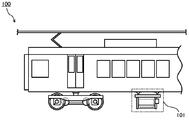
- FIG. 5 is a diagram illustrating an example of a railway vehicle 100 that includes the rotating electrical machine 101.
- the rotating electrical machine 101 the motors shown in FIGS. 3 and 4 and the generator shown in FIG. 4 can be used.
- the rotating electrical machine 101 uses, for example, power supplied from an overhead wire or power supplied from a secondary battery mounted on the railway vehicle 100 to drive power. May be used as an electric motor (motor) that outputs power, or may be used as a generator (generator) that converts kinetic energy into electric power and supplies electric power to various loads in the railway vehicle 100.
- the railway vehicle can be run with energy saving.
- the rotating electric machine may be mounted on a vehicle (another example of a vehicle) such as a hybrid vehicle or an electric vehicle.
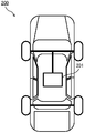
- FIG. 6 is a diagram illustrating an example of an automobile 200 that includes the rotating electrical machine 201.
- the rotating electrical machine 201 the motor shown in FIGS. 2 and 3, the generator shown in FIG. 4 and the like can be used.
- the rotating electrical machine 201 may be used as an electric motor that outputs the driving force of the automobile 200, or a generator that converts kinetic energy during travel of the automobile 200 into electric power.
- the rotating electrical machine may be mounted on, for example, industrial equipment (industrial motor), air conditioning equipment (air conditioner / water heater compressor motor), wind power generator, or elevator (winding machine).
- Example 1 The raw materials were prepared at a predetermined ratio so as to have an alloy powder composition shown in Table 1 and a composition of Sm (Cr 0.08 Si 0.03 Fe 0.89 ) 8.3 .
- An alloy ingot was prepared by arc melting the raw material blended in an argon gas atmosphere. The alloy ingot was heat-treated at about 1000 ° C. for about 3 days in an argon gas atmosphere. Thereafter, the alloy ingot was pulverized in a mortar to obtain an alloy powder. The alloy powder was sieved with a sieve having an opening of 25 ⁇ m. The alloy powder was heat-treated at 700 ° C. for 4 hours in a nitrogen gas atmosphere at about 1 atm to obtain a nitride alloy powder.
- Oleic acid was added to the resulting nitrided alloy powder to a weight ratio of 5% and kneaded by a ball mill.
- the obtained powder was filled in a mold while orientation-pressing in a magnetic field, and then subjected to discharge plasma sintering under a pressure of 1.0 GPa and a sintering temperature of 600 ° C. to obtain a permanent magnet.
- the composition of the permanent magnet was the magnet composition shown in Table 1.
- Table 2 shows the specific surface area of the ⁇ -Fe phase, the volume ratio of the oxide phase, and the coercive force in the permanent magnet of Example 1.
- the coercive force is shown as a relative value when the coercive force of the permanent magnet of Comparative Example 1 described later is 100.
- Example 2 to 16 The raw materials were prepared at a predetermined ratio so that the alloy powder composition had the values shown in Table 1. Further, oleic acid or stearic acid was added in a weight ratio of 5% so that the organic compound added to the nitride alloy powder had the combination shown in Table 1, and kneaded by a ball mill. Other than that, permanent magnets were produced in the same manner as in Example 1. The characteristics of the obtained permanent magnet were evaluated in the same manner as in Example 1. Table 2 shows values of the specific surface area of the ⁇ -Fe phase, the volume ratio of the oxide phase, and the coercive force in the permanent magnets of Examples 2 to 16.
- Example 1 A permanent magnet was produced in the same manner as in Example 1 except that the oleic acid was not added to the nitride alloy powder and the next step was performed as it was. The characteristics of the obtained permanent magnet were evaluated in the same manner as in Example 1. Table 2 shows values of the specific surface area of the ⁇ -Fe phase, the volume ratio of the oxide phase, and the coercive force in the permanent magnet of Comparative Example 1.
- Example 2 A permanent magnet was produced in the same manner as in Example 1 except that the sintering temperature in the discharge plasma sintering was 350 ° C. The characteristics of the obtained permanent magnet were evaluated in the same manner as in Example 1. Table 2 shows the specific surface area of the ⁇ -Fe phase, the volume ratio of the oxide phase, and the coercive force in the permanent magnet of Comparative Example 2.
- Permanent magnets (Examples 1 to 16) in which oleic acid or stearic acid is added to the nitride alloy powder and sintered at a temperature higher than the boiling point thereof have higher coercive force than Comparative Examples 1 and 2. It was confirmed to have. This indicates that by forming a fine oxide phase on the surface of the nitride alloy powder, the specific surface area of the ⁇ -Fe phase is reduced, and the reduction in the coercive force of the permanent magnet can be suppressed.
Landscapes
- Engineering & Computer Science (AREA)
- Chemical & Material Sciences (AREA)
- Power Engineering (AREA)
- Mechanical Engineering (AREA)
- Inorganic Chemistry (AREA)
- Materials Engineering (AREA)
- Crystallography & Structural Chemistry (AREA)
- Metallurgy (AREA)
- Organic Chemistry (AREA)
- Manufacturing & Machinery (AREA)
- Physics & Mathematics (AREA)
- Electromagnetism (AREA)
- Hard Magnetic Materials (AREA)
- Permanent Field Magnets Of Synchronous Machinery (AREA)
- Powder Metallurgy (AREA)
Abstract
永久磁石は、組成式:RMZNXで表され、Th2Ni17型、Th2Zn17型、及びTbCu7型から選ばれる少なくとも一つの結晶構造を有する主相と、酸化物相及びα-Fe相を含む副相と、を具備する。主相及び副相の総量に対する酸化物相の体積比率は3%以上8%以下である。α-Fe相の比表面積は、5μm-1以下である。
Description
実施形態は、永久磁石、回転電機、及び車両に関する。
高性能な永久磁石として、Sm-Co系磁石やNd-Fe-B系磁石等の希土類磁石が知られている。希土類磁石は、モータ、スピーカ、計測器等の電気機器、さらにハイブリッド自動車(Hybrid Electric Vehicle:HEV)や電気自動車(Electric Vehicle:EV)等の車両に用いられている。近年、各種電気機器に対して小型化の要求が高まっており、さらにHEVやEVで使用されるモータの需要が増加している。これらの要求に応えるために、最大磁気エネルギー積(BHmax)の向上を目指した永久磁石の開発が望まれている。
より高性能の永久磁石を得るための磁石材料としては、例えば希土類元素とFe等の遷移金属元素との組み合わせが有望である。Sm-Fe-N系材料は、Nd-Fe-B系材料に匹敵する高い飽和磁化と、Nd-Fe-B系材料を超える大きな磁気異方性を有するため、高性能磁石としての応用が期待されている。
Sm-Fe-N系磁石材料は約550℃以上の温度による加熱で熱分解してしまうという欠点を有しているため、高い密度を得るために焼結による高密度化プロセスを適用すると、Sm-Fe-N系磁石材料が熱分解され、α-Fe相が析出してしまう。
実施形態が解決しようとする課題は、永久磁石の保磁力の低下を抑制することである。
実施形態の永久磁石は、組成式:RMZNX(Rは希土類元素、Zr、Nb、及びHfからなる群より選ばれる少なくとも一つの元素、MはFe及びCoからなる群より選ばれる少なくとも一つの元素、Xは0.5≦X≦2.0を満足する原子比、Zは4≦Z≦13を満足する原子比である)で表され、Th2Ni17型、Th2Zn17型、及びTbCu7型から選ばれる少なくとも一つの結晶構造を有する主相と、酸化物相及びα-Fe相を含む副相と、を具備する。主相及び副相の総量に対する酸化物相の体積比率は3%以上8%以下である。α-Fe相の比表面積は5μm-1以下である。
以下図面を参照して、実施形態を説明する。同じ符号が付されているものは同様のものを示す。なお、図面は模式的又は概念的なものであり、各部分の厚みと幅との関係、部分間の大きさの比係数などは、必ずしも現実のものと同一とは限らない。また、同じ部分を表す場合であっても、図面により互いの寸法や比係数が異なって表される場合もある。
(第1の実施形態)
実施形態の永久磁石の例について説明する。図1は、永久磁石の断面のSEM(Scanning Electron Microscope)観察像の一例を示す図である。図1に示す組織は、主相1と、酸化物相2及びα-Fe相3を含む副相とを有する。主相1は永久磁石中の各結晶相及び非晶質相のうち、最も体積占有率が高い相である。酸化物相2は、主相1よりも体積占有率が低い相である。酸化物相2は、主相1とは異なる結晶相、又は非晶質相を有する。α-Fe相3は、酸化物相2と異なる異相である。
実施形態の永久磁石の例について説明する。図1は、永久磁石の断面のSEM(Scanning Electron Microscope)観察像の一例を示す図である。図1に示す組織は、主相1と、酸化物相2及びα-Fe相3を含む副相とを有する。主相1は永久磁石中の各結晶相及び非晶質相のうち、最も体積占有率が高い相である。酸化物相2は、主相1よりも体積占有率が低い相である。酸化物相2は、主相1とは異なる結晶相、又は非晶質相を有する。α-Fe相3は、酸化物相2と異なる異相である。
実施形態の永久磁石の組成は下記組成式(1)で表される。
RMZNX・・・(1)
(式中Rは希土類元素、Zr、Nb、及びHfからなる群より選ばれる少なくとも一つの元素、MはFe及びCoからなる群より選ばれる少なくとも一つの元素、Xは0.5≦X≦2.0を満足する原子比、Zは4≦Z≦13を満足する原子比である。)
RMZNX・・・(1)
(式中Rは希土類元素、Zr、Nb、及びHfからなる群より選ばれる少なくとも一つの元素、MはFe及びCoからなる群より選ばれる少なくとも一つの元素、Xは0.5≦X≦2.0を満足する原子比、Zは4≦Z≦13を満足する原子比である。)
組成式(1)において、Rは希土類元素、ジルコニウム(Zr)、ニオブ(Nb)、及びハフニウム(Hf)から選ばれる少なくとも一つの元素である。希土類元素としては、例えば、イットリウム(Y)、ランタン(La)、セリウム(Ce)、プラセオジム(Pr)、ネオジム(Nd)、及びサマリウム(Sm)等が挙げられる。Rとしては、1種の元素を用いてもよいし、複数種の元素を用いてもよい。Rは、磁石に大きな磁気異方性と高い保磁力を付与する。Rの50原子%以上がSmであることが好ましい。Rの70原子%以上がSmであることが望ましい。Rに希土類元素を用いることによって、永久磁石の性能、とりわけ保磁力を再現性よく高めることができる。
窒素(N)は、主相1及び副相の結晶格子中に存在する。結晶格子中に窒素を含むと、結晶格子は拡大し、電子構造が変化する。これにより、永久磁石のキュリー温度、磁気異方性、及び飽和磁化が向上する。窒素の原子比はRが1のときに、0.5以上2.0以下である。つまりXは0.5≦X≦2.0を満足する原子比である。Xは1.0≦X≦1.5を満足する原子比であることがより好ましい。Xが0.5未満である場合、永久磁石に窒素を含有することによる効果を十分に得ることができない。Xが2.0を超えると、永久磁石の飽和磁化等が低下する。
Nの一部は、水素(H)、ホウ素(B)、及び炭素(C)から選ばれる少なくとも一つの元素で置換されてもよい。上記置換元素としては、1種の元素を用いてもよいし、複数種の元素を用いてもよい。上記置換元素は、上述した窒素と同様の効果を示す。ただし、窒素を過剰に置換すると、永久磁石の磁気異方性の低下等を招く。よって、窒素の50原子%以下が上記元素に置換されることが好ましい。
Mは、鉄(Fe)及びコバルト(Co)から選ばれる少なくとも一つの元素である。Mとしては、1種の元素を用いてもよいし、複数種の元素を用いてもよい。Mは、主として永久磁石の磁化を担う元素である。Mを比較的多量に含有することにより、永久磁石の飽和磁化を高めることができる。ただし、Mの含有量が過剰になると、α‐Fe相等が析出して保磁力が低下する。
Mの50原子%以上はFeであることが好ましい。さらにMの70原子%以上はFeであることがより好ましい。MのうちのFeは、特に永久磁石の磁化の向上に寄与する。永久磁石がMの一部としてCoを含有することにより、永久磁石のキュリー温度が高くなり、永久磁石の熱安定性が向上する。また、永久磁石の保磁力も高くなる。
Mの一部は、チタン(Ti)、バナジウム(V)、タンタル(Ta)、モリブデン(Mo)、タングステン(W)、マンガン(Mn)、ニッケル(Ni)、亜鉛(Zn)、及びゲルマニウム(Ge)から選ばれる少なくとも一つの元素で置換されてもよい。置換元素としては、1種の元素を用いてもよいし、複数種の元素を用いてもよい。Mの一部を置換する元素は、磁気特性、例えば、保磁力の向上に寄与する。ただし、Mの一部を置換しすぎると、永久磁石の磁化は低下する。従って、Mの20原子%以下、さらにはMの10原子%以下が上記元素で置換されることが好ましい。
Mの一部は、クロム(Cr)及びケイ素(Si)からなる群より選ばれる少なくとも一つの元素で置換されてもよい。Cr、SiはR-M-N系永久磁石の熱分解温度を上昇させる。Cr又はSiは、主として主相中のMが占めるサイトを置換する。Crは結晶内のd電子の数を変化させることにより結晶の熱安定性を高めることができる。Siは結晶格子の大きさを縮小させることにより結晶の熱安定性を高めることができる。Cr及びSiを永久磁石中に含有させることにより、焼結工程におけるR-M-N系永久磁石の熱分解を抑制し、α-Fe相の析出を抑制することができる。Mの20原子%以下、さらにはMの10原子%以下が上記元素で置換されることが好ましい。
主相1は、Th2Ni17型、Th2Zn17型、及びTbCu7型から選ばれる少なくとも一つの結晶構造を有する。主相1は、例えばSm2(Fe,Cr,Si)17N3相等のR-M-N相を有する。
酸化物相2としては、例えばRの酸化物相等が挙げられる。永久磁石中の酸化物相2は、多量に存在すると永久磁石の飽和磁化を低下させるため、少ないことが好ましい。また、永久磁石中にα-Fe相3が存在すると、主相との界面近傍で磁化反転核を生成し易く、永久磁石の保磁力を低下させる要因となる。また、永久磁石中のα-Fe相3の体積比率が同じ場合でも、α-Fe相3の形状が針状になるほど比表面積が増加して主相との接触界面が増加し、保磁力が低下しやすくなる。
実施形態の永久磁石では、主相1の結晶粒子間あるいは粒子表面に適量の酸化物相2を有することにより、焼結時の熱分解により生成されたα-Fe相3の形状が粒状になるように制御し、α-Fe相3の比表面積を低下させることができる。α-Fe相3の比表面積は、5μm-1以下であることが好ましい。α-Fe相3の比表面積を低下させることにより永久磁石の保磁力を向上させることができる。α-Fe相3の比表面積は、例えばα-Fe相3の単位体積あたりの表面積により定義されてもよい。比表面積が最小値となるのは結晶粒子が球体の場合である。よって、比表面積の下限値は一義的に求められる。
飽和磁化の低下を防ぐために、酸化物相2の総量の体積比率は8%以下であることが好ましいが、酸化物相2の存在によってα-Fe相3の比表面積を低下させる効果を得るためには、酸化物相2の総量の体積比率は3%以上であることが好ましい。また、永久磁石中のα-Fe相3の総量の体積比率は、5%以下であることが好ましい。
永久磁石の組成の分析は、例えば誘導結合発光プラズマ(Inductively Coupled Plasma:ICP)発光分光分析法で行われる。永久磁石の組成の分析には、磁石をジェットミルやボールミル等で粉砕し、粒径が10μm以上の粉末が体積%で全体の3%以下となる粉末(合金粉末)を用いる。得られた粉末からランダムに10回試料を採取し、その試料に対し分析を実施する。分析した測定値から最大値と最小値を除いた平均値を永久磁石の組成とする。
主相1、酸化物相2、及びα-Fe相3は、例えばSEM-EDX(Scanning Electron Microscope-Energy Dispersive X-ray Spectroscopy)、TEM-EDX(Transmission Electron Microscope-Energy Dispersive X-ray Spectroscopy)などの方法で特定することができる。TEM-EDXによれば、電子ビームを主相部分や粒界相部分などに絞って照射し、各部分の構成元素比を定量でき、また結晶構造を同定することができる。
SEM-EDXを用いた主相1、酸化物相2、及びα-Fe相3の同定方法について以下に説明する。観察面積50μm×50μmのSEM像を取得する。SEM像内でO元素の濃度が40原子%上の連続領域を酸化物相2、O元素の濃度が40原子%未満かつR元素濃度が10原子%以上の連続領域を主相1、O元素の濃度が40原子%未満かつR元素濃度が10原子%未満であってFe濃度が90原子%以上である連続領域をα-Fe相3とそれぞれ定義する。
同じ観察視野内で上記に従って定義した主相1・α-Fe相3と酸化物相2との面積比率を、そのまま体積比率として算出した値を、永久磁石中の酸化物相の体積比率と定義する。同様に、主相1・酸化物相2とα-Fe相3との面積比率を、そのまま体積比率として算出した値を、永久磁石中のα-Fe相の体積比率と定義する。一つの永久磁石につき、5つの観察視野で以上に述べた方法によって酸化物相の体積比率、α-Fe相3の体積比率をそれぞれ算出し、加算平均したものをその永久磁石の酸化物相の体積比率、α-Fe相3の体積比率と定義する。
SEM像内でα-Fe相と定義された連続領域について長軸及び短軸方向の長さをそれぞれ計測し、これを回転楕円体の長軸及び短軸長さと仮定して比表面積を算出する。長軸は、例えば連続領域の周縁上の2点を結ぶ直線を引いたときに最長となる直線(第1の直線)により定義されてもよい。短軸は、例えば第1の直線に垂直であって連続領域の周縁上の2点を結ぶ直線を引いたときに、最長となる直線(第2の直線)により定義されてもよい。一つの永久磁石につき、5つの観察視野について同じ観察視野内でα-Fe相と定義された全ての連続領域について比表面積を算出し、加算平均したものをその永久磁石のα-Fe相の比表面積と定義する。
実施形態の永久磁石は、熱安定性の低いα-Fe相の比表面積を低減することにより保磁力を低下させることなく永久磁石の密度を向上させることができる。例えば、実施形態の永久磁石は、6.5g/cm3以上の密度を有する。永久磁石の密度は、永久磁石の大気中及び水中での質量をそれぞれ測定し、アルキメデス法により算出される。このとき、一つの試料につきそれぞれ10回算出し、得られた永久磁石の密度のうち最大値と最小値を除いた平均の値を永久磁石の密度と定義する。
次に、実施形態の永久磁石の製造方法例について説明する。まず、所定量の元素を含む合金粉末を作製する。合金粉末は、組成式(2)で表される。なお、合金粉末は水素、ホウ素、及び炭素からなる群より選ばれる少なくとも一つの元素を含んでいてもよい。
RMZ・・・(2)
RMZ・・・(2)
組成式(2)において、Rに対するそれ以外のMの合計の含有量の比を示す原子比Zは、4≦Z≦13を満足する数である。
合金粉末は、例えば、アーク溶解法や高周波溶解法による溶湯を鋳造して得られた合金インゴット、あるいは溶湯急冷法により作製した合金薄帯を粉砕することにより調製される。合金粉末の他の調製方法としては、メカニカルアロイング法やメカニカルグラインディング法、ガスアトマイズ法、還元拡散法等が挙げられる。合金粉末又は粉砕前の合金に対して、必要に応じて熱処理を施して均質化してもよい。
合金インゴットや合金薄帯等の粉砕は、合金粉末の粒径が45μm以下となるように実施することが好ましい。合金粉末の粒径が45μm以下であると、粒子内部まで窒素を十分に侵入させ、粒子全体にわたって均質に窒化処理することができる。合金インゴットや合金薄帯等の粉砕は、例えば、ジェットミルやボールミルを用いて実施される。合金インゴットや合金薄帯等の粉砕は、合金粉末の酸化を防止するために、不活性ガス雰囲気中等で行うことが好ましい。
次に、合金粉末に窒化処理を施す。窒化処理では、0.1~100気圧の窒素ガス雰囲気中で、300~900℃の温度で0.1~100時間熱処理する。R-M-N相の均質性を高めるために、窒素ガス雰囲気の圧力は0.5~10気圧、温度は450~750℃、2~24時間で窒化処理することがより好ましい。合金粉末の窒化処理時の雰囲気は、窒素ガスに代えてアンモニア等の窒素化合物ガスを用いてもよい。窒素ガス又は窒素化合物ガスと水素とを混合したガスを用いることにより、窒化反応を制御することもできる。
アンモニア等の窒素化合物ガスや、窒素ガスと水素ガスとの混合ガスを用いることにより、磁石材料中の窒素の一部を水素で置換することができる。窒素の一部を炭素やホウ素で置換する場合には、窒化処理前の合金粉末に炭素やホウ素を含有させてもよいし、炭素化合物ガスやホウ素化合物ガス等を用いて炭素やホウ素を含有させてもよい。
窒化処理を施した合金粉末に、酸素原子を含む有機化合物を添加する。酸素原子を含む有機化合物としては、例えばステアリン酸やオレイン酸等の脂肪酸を用いることができる。脂肪酸は水酸基を有し揮発性に乏しいため、後の焼結工程まで粉末表面を保護し表面酸化等による性能の劣化を防ぐとともに、一般に高級脂肪酸でも400℃程度まで加熱すれば揮発あるいは熱分解するため、焼結工程においては粉末表面を均一かつ適度に酸化させる酸素原子の供給源として効率的に機能する。以上のような特性から、永久磁石を製造する場合に添加する有機化合物として脂肪酸が適しているといえる。
有機化合物の添加は、混合器などによって窒化合金粉末と混練、ボールミルに分散剤として添加、ジェットミルにコート剤として添加するなどの方法を用いる。これにより、窒化合金粉末表面に脂肪酸が付着あるいは被覆した粉末を得ることができる。添加する脂肪酸の量が少なすぎると被覆による効果を十分に得ることができず、多すぎると被覆の厚さ、すなわち被覆部分の体積比率が大きくなり永久磁石の磁化を低下させる。添加する脂肪酸の量は、窒化合金粉末に対して重量比で0.01%以上10%以下とすることが好ましい。
次に、電磁石の中に設置した金型内に上記粉末(窒化合金粉末)を充填し、磁場を印加しながら加圧成形することにより結晶軸を配向させた圧粉体を製造する。
次に、圧粉体の焼結を行う。焼結方法としては、放電プラズマ焼結法を用いることが好ましい。放電プラズマ焼結では、粉末粒子の表面に選択的に電流が流れやすいと考えられており、R-M-N相にかかる熱負荷を抑制しつつ、永久磁石を高密度化させるのに適している。
焼結は、真空雰囲気中やアルゴンガス等の不活性ガス雰囲気中で行うことが好ましい。放電プラズマ焼結時は、添加した有機化合物の沸点あるいは分解温度よりも高い温度で行う。特に、焼結温度を400~700℃とすることにより、緻密な永久磁石を得ることができる。400℃未満では、十分な密度の永久磁石を得ることができない。700℃を超えると永久磁石の熱分解が進行し、永久磁石中にα-Fe相等が生成されるため、永久磁石の磁気特性が著しく低下する。
上記工程により永久磁石を得ることができる。得られた永久磁石の磁気特性は振動試料型磁力計で測定することができる。残留磁化の測定は以下のように行うことができる。焼結前に配向させた磁化方向と平行な方向に外部磁場を+1600kA/mまで印加してから磁場をゼロに戻し、そのときに測定される磁化の値を永久磁石の残留磁化と定義する。永久磁石試料の測定とは別に、測定する試料と類似形状のニッケル標準試料(磁化の絶対値が既知の試料)についても同様の測定を行い、磁化の絶対値を較正する。
実施形態の永久磁石の製造方法例では、焼結時に窒化合金粉末に添加した有機化合物の沸点あるいは分解温度よりも高い温度とすることで、窒化合金粉末表面と有機化合物に含まれる酸素原子を反応させ、窒化合金粉末表面に微小な酸化物相を形成させる。この微小な酸化物相が存在することで、焼結時にR-M-N相が熱分解することによって結晶粒子間に生成するα-Fe相の連続的な形成が遮断され、α-Fe相の比表面積が低下する。結果として、上述したように、α-Fe相の生成による永久磁石の保磁力低下を抑制することができる。
(第2の実施形態)
第1の実施形態の永久磁石は、回転電機、例えばモータや発電機に用いることができる。これら回転電機は、少なくともステータ(固定子)とロータ(回転子)で構成される。
第1の実施形態の永久磁石は、回転電機、例えばモータや発電機に用いることができる。これら回転電機は、少なくともステータ(固定子)とロータ(回転子)で構成される。
図2は実施形態の永久磁石を用いた回転電機である永久磁石モータの構成例を示す図である。永久磁石モータ21は、ステータ(固定子)22、ロータ(回転子)23で構成される。ステータ22内にはロータ23が配置されている。ステータ22は、ロータ23を回転させる。ロータ23は鉄心24及び実施形態の永久磁石25で構成される。永久磁石25の特性等に基づいて、永久磁石モータ21の高効率化や小型化、低コスト化等を図ることができる。永久磁石モータ21は、モータの高出力とモータの小型化が求められるハイブリッド車や電気自動車等の車両用のモータに好適である。
図3は回転電機である可変磁束モータの構成例を示す図である。可変磁束モータ31はステータ32、ロータ33で構成される。ステータ32内にはロータ33が配置されている。ロータ33は、鉄心34、固定磁石35、可変磁石36で構成される。固定磁石35及び可変磁石36は、実施形態の永久磁石が用いられる。固定磁石35及び可変磁石36のうち少なくとも1つをロータ33に用いればよい。
可変磁石36の磁束密度(磁束量)は変えることができる。図3中のDは可変磁石36の磁化方向(SからNに向かう方向)を示している。この可変磁石36の磁化方向をD軸という。D軸の示す方向は可変磁石36ごとに異なる。D軸と直交する方向をQ軸という。可変磁石36の磁束密度(磁束量)は、可変磁石36の磁化方向(D軸方向)と直交するQ軸方向に磁界を発生させるQ軸電流の影響を受けない。可変磁石36の磁束密度(磁束量)は、D軸方向に磁界を発生させるD軸電流によってのみ変化させることができる。
ロータ33には、図示しない磁化巻線が設けられている。磁化巻線に電流を流すことにより、その磁界が直接に可変磁石36に作用する構造となっている。可変磁束モータ31は、小型の装置でも大きなトルクを出力することが可能である。可変磁束モータ31は、モータの高出力とモータの小型化が求められるハイブリッド車や電気自動車等の車両用のモータに好適である。
図4は発電機の構成例を示す図である。発電機41は、実施形態の永久磁石を用いたステータ42、ロータ43、タービン44、シャフト45、及びブラシ46で構成される。ロータ43は、シャフト45を介してタービン44と接続されている。タービン44は、外部から供給される流体により回転する。タービン44に代えて、自動車等の車両の回生エネルギー等の動的な回転を伝達することにより、シャフト45を回転させてもよい。シャフト45は、ロータ43に対してタービン44とは反対側に配置された図示しない整流子と接続されている。ロータ43の回転により発生した起電力が発電機41の出力として、相分離母線及び主変圧器を介して、系統電圧に昇圧されて送電される。ブラシ46は、ロータ43の帯電を放電させる。
発電機41は、通常の発電機及び可変磁束発電機のいずれであってもよい。ロータ43では、タービン44の静電気や発電に伴う軸電流による帯電が発生する。
上記回転電機は、例えば、鉄道交通に利用される鉄道車両(車両の一例)に搭載されてよい。図5は、回転電機101を具備する鉄道車両100の一例を示す図である。回転電機101としては、上記図3、4のモータ、図4の発電機等を用いることができる。回転電機101として上記回転電機が搭載された場合、回転電機101は、例えば、架線から供給される電力や、鉄道車両100に搭載された二次電池から供給される電力を利用することによって駆動力を出力する電動機(モータ)として利用されてもよいし、運動エネルギーを電力に変換して、鉄道車両100内の各種負荷に電力を供給する発電機(ジェネレータ)として利用されてもよい。実施形態の回転電機のような高効率な回転電機を利用することにより、省エネルギーで鉄道車両を走行させることができる。
上記回転電機は、ハイブリッド自動車や電気自動車などの自動車(車両の他の例)に搭載されてもよい。図6は、回転電機201を具備する自動車200の一例を示す図である。回転電機201としては、上記図2、3のモータ、図4の発電機等を用いることができる。回転電機201として上記回転電機が搭載された場合、回転電機201は、自動車200の駆動力を出力する電動機、又は自動車200の走行時の運動エネルギーを電力に変換する発電機としても利用されてよい。また、上記回転電機は、例えば産業機器(産業用モータ)、空調機器(エアコンディショナ・給湯器コンプレッサモータ)、風力発電機、又はエレベータ(巻上機)に搭載されてもよい。
(実施例1)
原料を表1に示す合金粉末組成、Sm(Cr0.08Si0.03Fe0.89)8.3の組成となるように所定の比率で調合した。原料を調合したものをアルゴンガス雰囲気中でアーク溶解して合金インゴットを作製した。合金インゴットをアルゴンガス雰囲気中、約1000℃で約3日間熱処理した。その後、乳鉢で合金インゴットを粉砕し合金粉末を得た。合金粉末を目開き25μmのふるいでふるい分けした。合金粉末を約1気圧の窒素ガス雰囲気中、700℃で4時間熱処理することにより、窒化合金粉末を得た。得られた窒化合金粉末に対して重量比で5%となるようオレイン酸を添加し、ボールミルによって混練した。得られた粉末を磁場中で配向プレスしながら金型に充填した後、粉末に圧力1.0GPa、焼結温度600℃の条件で放電プラズマ焼結を施して永久磁石を得た。永久磁石の組成は表1に示す磁石組成となった。
原料を表1に示す合金粉末組成、Sm(Cr0.08Si0.03Fe0.89)8.3の組成となるように所定の比率で調合した。原料を調合したものをアルゴンガス雰囲気中でアーク溶解して合金インゴットを作製した。合金インゴットをアルゴンガス雰囲気中、約1000℃で約3日間熱処理した。その後、乳鉢で合金インゴットを粉砕し合金粉末を得た。合金粉末を目開き25μmのふるいでふるい分けした。合金粉末を約1気圧の窒素ガス雰囲気中、700℃で4時間熱処理することにより、窒化合金粉末を得た。得られた窒化合金粉末に対して重量比で5%となるようオレイン酸を添加し、ボールミルによって混練した。得られた粉末を磁場中で配向プレスしながら金型に充填した後、粉末に圧力1.0GPa、焼結温度600℃の条件で放電プラズマ焼結を施して永久磁石を得た。永久磁石の組成は表1に示す磁石組成となった。
表2に実施例1の永久磁石における、α-Fe相の比表面積、酸化物相の体積比率、及び保磁力の値を示す。保磁力は後述する比較例1の永久磁石の保磁力を100とした場合の相対値で示している。
(実施例2~16)
合金粉末組成が表1に示す値となるように原料を所定の比率で調合した。また、窒化合金粉末に添加する有機化合物を表1に示す組合せとなるようオレイン酸又はステアリン酸を、重量比で5%添加し、ボールミルによって混練した。その他は、実施例1の場合と同様の方法で永久磁石を作製した。得られた永久磁石の特性を実施例1の場合と同様に評価した。表2に実施例2~16の永久磁石における、α-Fe相の比表面積、酸化物相の体積比率、及び保磁力の値を示す。
合金粉末組成が表1に示す値となるように原料を所定の比率で調合した。また、窒化合金粉末に添加する有機化合物を表1に示す組合せとなるようオレイン酸又はステアリン酸を、重量比で5%添加し、ボールミルによって混練した。その他は、実施例1の場合と同様の方法で永久磁石を作製した。得られた永久磁石の特性を実施例1の場合と同様に評価した。表2に実施例2~16の永久磁石における、α-Fe相の比表面積、酸化物相の体積比率、及び保磁力の値を示す。
(比較例1)
窒化合金粉末に対してオレイン酸を添加せず、そのまま次の工程を行ったこと以外は、実施例1の場合と同様の方法で永久磁石を作製した。得られた永久磁石の特性を実施例1の場合と同様に評価した。表2に比較例1の永久磁石における、α-Fe相の比表面積、酸化物相の体積比率、及び保磁力の値を示す。
窒化合金粉末に対してオレイン酸を添加せず、そのまま次の工程を行ったこと以外は、実施例1の場合と同様の方法で永久磁石を作製した。得られた永久磁石の特性を実施例1の場合と同様に評価した。表2に比較例1の永久磁石における、α-Fe相の比表面積、酸化物相の体積比率、及び保磁力の値を示す。
(比較例2)
放電プラズマ焼結における焼結温度を350℃としたこと以外は、実施例1の場合と同様の方法で永久磁石を作製した。得られた永久磁石の特性を実施例1の場合と同様に評価した。表2に比較例2の永久磁石における、α-Fe相の比表面積、酸化物相の体積比率、及び保磁力の値を示す。
放電プラズマ焼結における焼結温度を350℃としたこと以外は、実施例1の場合と同様の方法で永久磁石を作製した。得られた永久磁石の特性を実施例1の場合と同様に評価した。表2に比較例2の永久磁石における、α-Fe相の比表面積、酸化物相の体積比率、及び保磁力の値を示す。

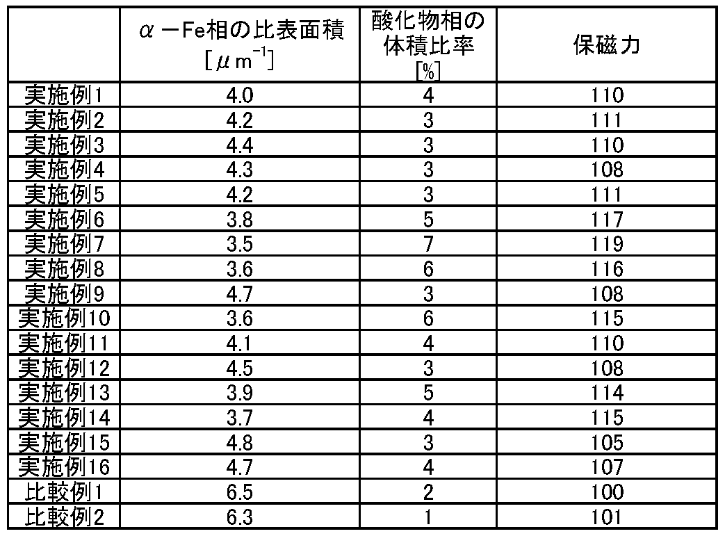
窒化合金粉末に対してオレイン酸あるいはステアリン酸を添加し、これらの沸点よりも高い温度で焼結を施した永久磁石(実施例1~16)では、比較例1及び2よりも高い保磁力を有することが確認された。これは窒化合金粉末表面に微小な酸化物相を形成することによりα-Fe相の比表面積が低下し、永久磁石の保磁力低下を抑制できたことを示している。
なお、本発明のいくつかの実施形態を説明したが、これらの実施形態は例として提示したものであり、発明の範囲を限定することは意図していない。これら新規な実施形態は、その他の様々な形態で実施し得るものであり、発明の要旨を逸脱しない範囲で、種々の省略、置き換え、変更を行うことができる。これら実施形態やその変形は、発明の範囲や要旨に含まれると共に、特許請求の範囲に記載された発明とその均等の範囲に含まれる。
Claims (13)
- 組成式:RMZNX
(Rは希土類元素、Zr、Nb、及びHfからなる群より選ばれる少なくとも一つの元素、MはFe及びCoからなる群より選ばれる少なくとも一つの元素、Xは0.5≦X≦2.0を満足する原子比、Zは4≦Z≦13を満足する原子比である)
で表され、
Th2Ni17型、Th2Zn17型、及びTbCu7型から選ばれる少なくとも一つの結晶構造を有する主相と、
酸化物相及びα-Fe相を含む副相と、を具備し、
前記主相及び前記副相の総量に対する前記酸化物相の総量の体積比率は、3%以上8%以下であり、
前記α-Fe相の比表面積は、5μm-1以下である、永久磁石。 - 前記酸化物相は、前記Rの酸化物を含む、請求項1に記載の永久磁石。
- 前記Rの50原子%以上はSmである、請求項1又は請求項2に記載の永久磁石。
- 前記Mの50原子%以上はFeである、請求項1ないし請求項3のいずれか一項に記載の永久磁石。
- 前記Mの20原子%以下は、Cr及びSiからなる群より選ばれる少なくとも一つの元素で置換されている、請求項1ないし請求項4に記載の永久磁石。
- 前記Mの20原子%以下は、Ti、V、Ta、Mo、W、Mn、Ni、Zn、及びGeから選ばれる少なくとも一つの元素で置換されている、請求項1ないし請求項4のいずれか一項に記載の永久磁石。
- 前記Nの50原子%以下が、H、B、及びCから選ばれる少なくとも一つの元素で置換されている、請求項1ないし請求項6のいずれか一項に記載の永久磁石。
- 前記永久磁石の密度は6.5g/cm3以上である、請求項1ないし請求項7のいずれか一項に記載の永久磁石。
- 前記永久磁石中のα-Fe相の総量の体積比率は、5%以下である、請求項1ないし請求項8のいずれか一項に記載の永久磁石。
- ロータと、
ステータと、を具備し、
前記ロータ又は前記ステータは、請求項1ないし請求項9のいずれか一項に記載の永久磁石を有する、回転電機。 - モータ又は発電機である請求項10に記載の回転電機。
- 請求項10又は請求項11に記載の回転電機を具備する、車両。
- 請求項10に記載の回転電機を具備し、
前記回転電機の一端に設けられたシャフトに回転が伝達される、車両。
Applications Claiming Priority (2)
| Application Number | Priority Date | Filing Date | Title |
|---|---|---|---|
| JP2017-056047 | 2017-03-22 | ||
| JP2017056047A JP2020080336A (ja) | 2017-03-22 | 2017-03-22 | 永久磁石、回転電機、及び車両 |
Publications (1)
| Publication Number | Publication Date |
|---|---|
| WO2018173783A1 true WO2018173783A1 (ja) | 2018-09-27 |
Family
ID=59955331
Family Applications (1)
| Application Number | Title | Priority Date | Filing Date |
|---|---|---|---|
| PCT/JP2018/009080 Ceased WO2018173783A1 (ja) | 2017-03-22 | 2018-03-08 | 永久磁石、回転電機、及び車両 |
Country Status (3)
| Country | Link |
|---|---|
| JP (1) | JP2020080336A (ja) |
| CN (1) | CN108631454A (ja) |
| WO (1) | WO2018173783A1 (ja) |
Cited By (2)
| Publication number | Priority date | Publication date | Assignee | Title |
|---|---|---|---|---|
| CN112530653A (zh) * | 2019-09-17 | 2021-03-19 | 株式会社东芝 | 磁铁材料、永磁铁、旋转电机及车辆 |
| JP2021180236A (ja) * | 2020-05-13 | 2021-11-18 | 学校法人千葉工業大学 | サマリウム−鉄−窒素系永久磁石材料の製造方法 |
Families Citing this family (1)
| Publication number | Priority date | Publication date | Assignee | Title |
|---|---|---|---|---|
| CN111180160A (zh) * | 2020-01-17 | 2020-05-19 | 杭州史宾纳科技有限公司 | 还原扩散各向同性钐铁氮粉末及磁体的工艺 |
Citations (4)
| Publication number | Priority date | Publication date | Assignee | Title |
|---|---|---|---|---|
| JP2004146713A (ja) * | 2002-10-28 | 2004-05-20 | Hitachi Metals Ltd | R−t−n系磁粉の製造方法およびr−t−n系ボンド磁石の製造方法 |
| WO2009057742A1 (ja) * | 2007-11-02 | 2009-05-07 | Asahi Kasei Kabushiki Kaisha | 磁石用複合磁性材料、及びその製造方法 |
| WO2016151619A1 (ja) * | 2015-03-23 | 2016-09-29 | 株式会社 東芝 | 磁石材料、永久磁石、モータ、および発電機 |
| JP2017112300A (ja) * | 2015-12-18 | 2017-06-22 | トヨタ自動車株式会社 | 希土類磁石 |
Family Cites Families (2)
| Publication number | Priority date | Publication date | Assignee | Title |
|---|---|---|---|---|
| CN1038795C (zh) * | 1993-12-24 | 1998-06-17 | 中国科学院物理研究所 | 3∶29相稀土铁氮化物永磁体及其制备方法 |
| JP3304726B2 (ja) * | 1995-11-28 | 2002-07-22 | 住友金属鉱山株式会社 | 希土類−鉄−窒素系磁石合金 |
-
2017
- 2017-03-22 JP JP2017056047A patent/JP2020080336A/ja active Pending
- 2017-09-12 CN CN201710817535.1A patent/CN108631454A/zh active Pending
-
2018
- 2018-03-08 WO PCT/JP2018/009080 patent/WO2018173783A1/ja not_active Ceased
Patent Citations (4)
| Publication number | Priority date | Publication date | Assignee | Title |
|---|---|---|---|---|
| JP2004146713A (ja) * | 2002-10-28 | 2004-05-20 | Hitachi Metals Ltd | R−t−n系磁粉の製造方法およびr−t−n系ボンド磁石の製造方法 |
| WO2009057742A1 (ja) * | 2007-11-02 | 2009-05-07 | Asahi Kasei Kabushiki Kaisha | 磁石用複合磁性材料、及びその製造方法 |
| WO2016151619A1 (ja) * | 2015-03-23 | 2016-09-29 | 株式会社 東芝 | 磁石材料、永久磁石、モータ、および発電機 |
| JP2017112300A (ja) * | 2015-12-18 | 2017-06-22 | トヨタ自動車株式会社 | 希土類磁石 |
Cited By (3)
| Publication number | Priority date | Publication date | Assignee | Title |
|---|---|---|---|---|
| CN112530653A (zh) * | 2019-09-17 | 2021-03-19 | 株式会社东芝 | 磁铁材料、永磁铁、旋转电机及车辆 |
| JP2021180236A (ja) * | 2020-05-13 | 2021-11-18 | 学校法人千葉工業大学 | サマリウム−鉄−窒素系永久磁石材料の製造方法 |
| JP7458067B2 (ja) | 2020-05-13 | 2024-03-29 | 学校法人千葉工業大学 | サマリウム-鉄-窒素系永久磁石材料の製造方法 |
Also Published As
| Publication number | Publication date |
|---|---|
| JP2020080336A (ja) | 2020-05-28 |
| CN108631454A (zh) | 2018-10-09 |
Similar Documents
| Publication | Publication Date | Title |
|---|---|---|
| JP7002868B2 (ja) | 磁石材料、永久磁石、回転電機、及び車両 | |
| WO2018173782A1 (ja) | 永久磁石、回転電機、及び車両 | |
| CN108347105A (zh) | 永久磁铁、旋转电机及车辆 | |
| JP6776441B2 (ja) | 磁石材料、永久磁石、回転電機、及び車両 | |
| US10923255B2 (en) | Magnetic material, permanent magnet, rotary electrical machine, and vehicle | |
| WO2018047211A1 (ja) | 永久磁石、回転電機、及び車両 | |
| JP2023085305A (ja) | 永久磁石、回転電機、及び車両 | |
| JP6189524B2 (ja) | 永久磁石とそれを用いたモータおよび発電機 | |
| CN107204224B (zh) | 永久磁铁、旋转电机及车辆 | |
| JP6596370B2 (ja) | 永久磁石、回転電機および車両 | |
| CN108631454A (zh) | 永久磁铁、旋转电机及车辆 | |
| US11289249B2 (en) | Permanent magnet, rotary electrical machine, and vehicle | |
| WO2016151619A1 (ja) | 磁石材料、永久磁石、モータ、および発電機 | |
| JP7278731B2 (ja) | 磁石材料、永久磁石、回転電機、及び車両 | |
| JP7150537B2 (ja) | 磁石材料、永久磁石、回転電機、及び車両 | |
| JP6613010B2 (ja) | 永久磁石、回転電機、及び車両 | |
| JP7797333B2 (ja) | 永久磁石、回転電機、車両、及び航空機 | |
| JP7234082B2 (ja) | 磁石材料、永久磁石、回転電機、及び車両 | |
| JP2023176479A (ja) | 永久磁石及び回転電機 | |
| JP2023137470A (ja) | 永久磁石、回転電機、車両、及び航空機 |
Legal Events
| Date | Code | Title | Description |
|---|---|---|---|
| 121 | Ep: the epo has been informed by wipo that ep was designated in this application |
Ref document number: 18771498 Country of ref document: EP Kind code of ref document: A1 |
|
| NENP | Non-entry into the national phase |
Ref country code: DE |
|
| 122 | Ep: pct application non-entry in european phase |
Ref document number: 18771498 Country of ref document: EP Kind code of ref document: A1 |
|
| NENP | Non-entry into the national phase |
Ref country code: JP |