WO2018173644A1 - 電動台車 - Google Patents
電動台車 Download PDFInfo
- Publication number
- WO2018173644A1 WO2018173644A1 PCT/JP2018/007097 JP2018007097W WO2018173644A1 WO 2018173644 A1 WO2018173644 A1 WO 2018173644A1 JP 2018007097 W JP2018007097 W JP 2018007097W WO 2018173644 A1 WO2018173644 A1 WO 2018173644A1
- Authority
- WO
- WIPO (PCT)
- Prior art keywords
- contact
- terminal
- state
- switched
- conductive
- Prior art date
- Legal status (The legal status is an assumption and is not a legal conclusion. Google has not performed a legal analysis and makes no representation as to the accuracy of the status listed.)
- Ceased
Links
Images




Definitions
- the present invention relates to an electric carriage.
- Patent Document 1 discloses a conventional electric cart.
- This electric cart is provided with a cargo loading platform above the chassis, a pair of left and right caster wheels arranged at the front of the chassis, and a pair of left and right drive wheels mounted on the rear, and the drive wheels
- Each electric motor (motor) can be driven forward and backward to run and steer forward and backward.
- the chassis is provided with a handle post, and grip portions are provided on both the left and right sides of the handle post.
- this electric carriage holds the grip and is pushed to the front side, the left and right drive wheels are rotated forward to travel forward. Further, when pulled rearward, the left and right drive wheels are reversely rotated to travel backward.
- the electric carriage is steered left and right by pushing one of the left and right grips to the front, or by pushing one of the left and right grips to the front and pulling the other to the rear.
- the present invention has been made in view of the above-described conventional situation, and an object to be solved is to provide an electric cart that can be easily handled without traveling carelessly.
- the electric cart of the present invention includes a frame, a power supply unit, a traveling unit, a first operation unit, a second operation unit, and a control unit.
- the frame incorporates a drive unit.
- the power supply unit supplies power to the drive unit.
- the traveling unit is provided on the frame and is driven by the drive unit.
- the first operation unit and the second operation unit are switched to the operated operation state or the non-operated non-operation state.
- the control unit switches the first operation unit and the second operation unit to the operation state, the control unit starts supplying power from the power supply unit to the drive unit, and in a state where power is supplied from the power supply unit to the drive unit, While either the first operation unit or the second operation unit is in the operating state, the supply of power from the power supply unit to the drive unit is continued.
- the first operation part of the electric cart of the present invention is operated with one hand of the user, and the second operation part is operated with the other hand of the user, and each of them can be switched between the operation state and the non-operation state. obtain.
- the control unit of the electric cart according to the present invention switches the first operation unit and the second operation unit to the non-operation state when power is supplied from the power supply unit to the drive unit.
- the supply of power to can be stopped.
- the controller of the electric cart of the present invention includes the first contact, the second contact, the third contact, the fourth contact, the fifth contact, the sixth contact, the seventh contact, the eighth contact, the first conductive path, and the second conductive.
- the first contact, the second contact, the third contact, the fourth contact, the fifth contact, the sixth contact, the seventh contact, and the eighth contact are electrically connected between one terminal and the other terminal, Or it can switch to the non-conduction state which does not conduct between one terminal and the other terminal.
- the first conductive path can be supplied with power from the power supply unit.
- the second conductive path may be at a lower potential than the first conductive path.
- the fifth contact and the sixth contact are switched to a conducting state, and when the energization is stopped, the fifth contact and the sixth contact are de-energized. You can switch.
- the seventh contact and the eighth contact are switched to the conductive state, and when the energization is stopped, the seventh contact and the eighth contact are switched to the nonconductive state. You can switch.
- one terminal of the first contact and the fifth contact is connected to the first conductive path, the other terminal of the first contact and the fifth contact and one terminal of the third contact are connected,
- the first coil may be interposed between the other terminal of the third contact and the second conductive path.
- one terminal of the fourth contact and the seventh contact is connected to the first conductive path, the other terminal of the fourth contact and the seventh contact and one terminal of the second contact are connected,
- a second coil may be interposed between the other terminal of the second contact and the second conductive path.
- the fifth conductive path has one terminal of the sixth contact and the eighth contact connected to the first conductive path, the other terminal of the sixth contact and the eighth contact connected, and the other of the sixth contact and the eighth contact.
- a driving unit may be interposed between the terminal and the second conductive path.
- the first operation unit may have a first contact and a second contact.
- the first contact point and the second contact point are switched to the operation state of the first operation unit, the first contact point and the second contact point are both switched to a conduction state in which the one terminal and the other terminal are electrically connected, and the first operation unit is switched to the non-operation state.
- Both can be switched to a non-conducting state in which the one terminal and the other terminal are not conducting.
- the second operation unit has a third contact and a fourth contact. When the second contact is switched to the operating state, the third contact and the fourth contact are both switched to a conductive state that conducts between one terminal and the other terminal, and the second operating portion is switched to the non-operating state.
- the control unit may include a first relay unit and a second relay unit.
- the first relay unit may include a fifth contact and a sixth contact, and a first coil.
- the fifth contact and the sixth contact can be switched together to a conductive state in which one terminal is electrically connected to the other terminal or a non-conductive state in which one terminal is not conductive to the other terminal.
- the second relay unit may include a seventh contact and an eighth contact, and a second coil.
- the seventh contact and the eighth contact can be switched to a conductive state in which one terminal is electrically connected to the other terminal, or a non-conductive state in which one terminal is not conductive to the other terminal.
- the seventh contact and the eighth contact are switched to the conductive state, and when the deenergization is stopped, the seventh contact and the eighth contact are switched to the nonconductive state. obtain.
- FIG. 1 It is a circuit diagram which shows the power supply part of the electric trolley
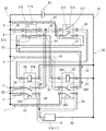
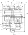
- FIG. 4 is a circuit diagram showing a power supply unit, a pair of operation switches, a control unit, and a motor of a drive unit of the electric carriage according to the embodiment, from the state in which the pressing parts of both operation switches are pressed, and the pressing of the other operation switch The part is not pressed.
- FIG. 1 For the front-rear direction, the left side in FIG. 1 is defined as the front side of the electric carriage, and the right side in FIG. 1 is defined as the rear side of the electric carriage.
- the vertical direction shown in FIGS. 1 and 3 is defined as the vertical direction of the electric carriage as it is.
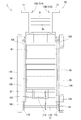
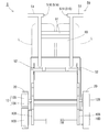
- the electric cart 1 of the embodiment is a device that moves up and down the stairs S. As shown in FIGS. 1 to 3, the electric cart 1 includes a frame 10, a crawler 20 that is a traveling unit, a cargo bed 40, a handle 50, an operation switch 51 ⁇ / b> A that is a first operation unit, and a second operation. An operation switch 51B, a control unit 80, and a battery 81 are provided.
- the frame 10 includes a horizontal portion 10A, an inclined portion 10B, a motor mounting portion 10C, a crawler guide portion 10D, a front bearing portion 10E, a rear bearing portion 10F, and a handle support portion. 10G.
- a drive unit 11 is incorporated in the frame 10.
- the horizontal portion 10A is provided with members extending in the front-rear direction arranged in parallel to the left and right.
- the inclined portion 10B is formed to extend rearward and obliquely upward from the rear end of the horizontal portion 10A.
- 10C of motor attachment parts are provided above the front-end part of the horizontal part 10A, and the motor 11A of the drive unit 11 mentioned later is attached.
- a pair of crawler guide portions 10D is provided on the left and right sides of the horizontal portion 10A and the inclined portion 10B.
- the crawler guide portion 10D is formed with a groove that opens downward and extends in the front-rear direction. As shown in FIG. 1, the crawler guide portion 10D is formed to extend along the direction in which the horizontal portion 10A and the inclined portion 10B extend in a side view.
- the front bearing portion 10E is provided so as to extend forward from the front ends of the left and right ends of the horizontal portion 10A.
- the front bearing portion 10E supports a drive shaft 11B of the drive unit 11 described later.
- the rear bearing portion 10F is formed to extend obliquely upward along the direction in which the inclined portion 10B extends from the rear ends of the left and right end portions of the inclined portion 10B.
- the rear bearing portion 10F supports a driven shaft 12A of a driven unit 12 described later.
- the handle support portion 10G is provided above the upper end portion of the inclined portion 10B and supports the lower end portion of the handle 50 described later.
- the drive unit 11 includes a motor 11A, a drive shaft 11B, and a drive pulley 11C.
- the motor 11A is a drive source of a crawler 20 described later, and is driven by power supplied from a battery 81 which is a power supply unit described later.
- the drive shaft 11B is pivotally supported by the front bearing portion 10E of the frame 10.
- the drive shaft 11B is rotated by the power of the motor 11A transmitted by a sprocket and a chain.
- the drive pulley (pulley) 11C is a toothed pulley around which the crawler 20 is wound.
- a follower unit 12 is incorporated in the frame 10.
- the driven unit 12 has a driven shaft 12A and a driven pulley 12B.
- the driven shaft 12A is pivotally supported by the rear bearing portion 10F of the frame 10.
- the crawler 20 is wound around the driven pulley 12B.
- a pair of crawlers 20 are provided on the left and right sides of the frame 10 and are driven by the drive unit 11.
- the crawler 20 has a substantially triangular ring shape when viewed from the side, and is wound around the drive pulley 11C, the driven pulley 12B, and the crawler guide portion 10D.
- the crawler 20 is a rubber crawler.
- the crawler 20 is provided with a plurality of teeth at predetermined intervals on the back surface thereof, and these teeth mesh with the teeth of the drive pulley 11C, and the power of the motor 11A is transmitted and driven.
- waved undulations are formed on the surface of the crawler 20 (the surface that contacts the stairs when the stairs are raised and lowered). As shown in FIG.
- the crawler 20 abuts against the corner of the staircase S at the side (lower side shown in FIG. 1) that is guided by the crawler guide portion 10 ⁇ / b> D when the staircase S moves up and down.
- the electric cart 1 moves up and down the stairs S by the crawler guide portion 10 ⁇ / b> D sliding on the back surface of the crawler 20.
- Each crawler 20 is wound around with a length that spans at least two or more corners of the staircase S so as to contact the ground when the stairs S are moved up and down.
- the loading platform 40 is arranged above the frame 10 and places the load L thereon. As shown in FIG. 1, the loading platform 40 has a placement surface portion 41 and a lower receiving portion 42.
- the mounting surface portion 41 is provided to extend rearward and obliquely upward from the lower end portion toward the upper end portion.
- the mounting surface portion 41 has a lower end supported by the horizontal portion 10A of the frame 10 and an upper end supported by the inclined portion 10B of the frame 10, and is inclined at an angle substantially parallel to the inclined portion 10B in a side view. Is provided.
- the lower receiving portion 42 is provided to extend obliquely upward and forward from the lower end of the placement surface portion 41.
- the loading platform 40 is formed in an approximately L shape in a side view by the placement surface portion 41 and the lower receiving portion 42.
- the lower receiving portion 42 receives the lower portion of the load L when the load L is placed on the placement surface portion 41.
- bogie 1 which concerns on this embodiment mounts a polytank (polyethylene tank) as the load L.
- FIG. 1 As shown in FIG. 1, a two-stage shelf 43 on which two 20-liter polytank tanks can be placed per stage is mounted between the placing surface part 41 and the lower receiving part 42. A maximum of four plastic tanks can be placed on the loading platform 40.
- the handle 50 is formed to extend rearward from the loading platform 40. Specifically, as shown in FIG. 1, the handle 50 is formed such that the lower end thereof is rotatably connected to the upper end portion of the placing surface portion 41 of the loading platform 40 and extends rearward and obliquely upward. At the upper end of the handle 50, a pair of grips 51 extending substantially horizontally in the left and right outer direction are provided.
- the pair of gripping portions 51 are portions that are gripped by a user who uses the electric cart 1 (hereinafter referred to as a user) and controls the traveling direction of the electric cart 1 or performs operations such as turning.
- the handle 50 is provided with an angle adjusting portion 52 that branches from the lower end portion and is connected to the handle support portion 10G of the frame 10.
- the angle adjusting unit 52 can adjust the angle of the handle 50 by rotating the entire handle 50 around the lower end of the handle 50 by adjusting the connection length with the handle support 10G.
- the operation switches 51A and 51B are provided at the left and right inner ends of the grip 51. These operation switches 51A and 51B operate the drive of the drive unit 11. One of these operation switches 51A and 51B is provided for each of the pair of grip portions 51.
- the operation switch 51 ⁇ / b> A includes a first contact 51 ⁇ / b> C, a second contact 51 ⁇ / b> D, and a pressing portion 51 ⁇ / b> G (see FIGS. 2 and 3).
- the first contact 51C is provided between the pair of terminals (see FIG. 6).
- the second contact 51D has the same configuration as the first contact 51C, and is provided between a pair of terminals (see FIG. 6).
- the pressing portion 51G is switched to a state pressed by the user (that is, an operated state) or a state where it is not pressed (that is, a non-operated state that is not operated).
- the pressing portion 51G When the pressing portion 51G is switched to a state pressed by the user, the pressing portion 51G conducts both the pair of terminals provided with the first contact 51C and the pair of terminals provided with the second contact 51D. Switch to conduction state. In addition, when the pressing portion 51G that has been pressed by the user is switched to a state in which it is not pressed, between the pair of terminals provided with the first contact 51C and between the pair of terminals provided with the second contact 51D. It switches to a non-conducting state where each of them is not conducting together.
- the pressing portion 51G of the operation switch 51A when the pressing portion 51G of the operation switch 51A is switched to the operation state, the first contact 51C and the second contact 51D are both one of the pair of terminals (hereinafter referred to as one terminal) and the other (hereinafter referred to as the other terminal). )). Further, when the pressing portion 51G of the operation switch 51A is switched to the non-operation state, both the first contact 51C and the second contact 51D are switched to the non-conduction state in which the connection between the one terminal and the other terminal is not established.
- the operation switch 51B includes a third contact 51E, a fourth contact 51F, and a pressing portion 51H (see FIGS. 2 and 3).
- the third contact 51E and the fourth contact 51F have the same configuration as the first contact 51C and the second contact 51D (see FIG. 6).
- the pressing portion 51H has the same configuration as the pressing portion 51G (not shown). That is, the pressing portion 51H is also switched to a state pressed by the user (that is, an operated operation state) or a state where it is not pressed (that is, a non-operated state that is not operated).
- both the pair of terminals provided with the third contact 51E and the pair of terminals provided with the fourth contact 51F are brought into conduction. Switch.
- One of these operation switches 51A and 51B is operated with one hand of the user, and the other is operated with the other hand of the user, and each of them can be switched to an operation state or a non-operation state.
- the operation switches 51A and 51B are provided with a pair of contacts (first contact 51C, second contact 51D, third contact 51E, and fourth contact 51F) when the pressing portions 51G and 51H are pressed.
- This is a momentary operation type push button switch that switches between a pair of terminals to a conductive state and automatically switches between a pair of terminals to a non-conductive state when the pressing portions 51G and 51H are not pressed.
- the operation switches 51A and 51B have a normally open (normally open) structure.
- the control unit 80 is provided on the handle 50 below the pair of gripping units 51 (see FIGS. 1 to 4).
- the control unit 80 controls the supply of power from the battery 81 to the drive unit 11.
- the control unit 80 includes a first contact 51C, a second contact 51D, a third contact 51E, a fourth contact 51F, a fifth contact 84B, a sixth contact 84C, a seventh contact 85B, and an eighth contact.
- 85C a first conductive path 82, a second conductive path 83, a first coil 84A, a second coil 85A, a third conductive path 86, a fourth conductive path 87, and a fifth conductive path 88.
- the first contact 51C, the second contact 51D, the third contact 51E, the fourth contact 51F, the fifth contact 84B, the sixth contact 84C, the seventh contact 85B, and the eighth contact 85C have the same configuration. It is configured to switch to a conductive state in which the terminal is electrically connected to the other terminal, or a non-conductive state in which the terminal is not conductive to the other terminal.
- the first conductive path 82 is electrically connected to a terminal on the high potential side of the battery 81, and power is supplied from the battery 81 (see FIG. 6).
- the second conductive path 83 has a lower potential than the first conductive path 82 and is electrically connected to a portion having a potential serving as a reference for the electric carriage 1 (see FIG. 6).
- a terminal on the low potential side of the battery 81 is electrically connected to the second conductive path 83 (see FIG. 6).
- the first coil 84A and the second coil 85A have the same configuration. Specifically, the first coil 84A and the second coil 85A are formed by winding a metal wire whose surface is covered with an insulating film a plurality of times coaxially, having a radial width, and bundling in a cylindrical shape ( Not shown). The first coil 84A and the second coil 85A are formed to extend in the cylindrical axial direction (not shown). A columnar iron core is inserted into the cylindrical inner sides of the first coil 84A and the second coil 85A (not shown). The first coil 84 ⁇ / b> A and the second coil 85 ⁇ / b> A are drawn out from both ends of the metal wire to form a pair of terminals.
- the fifth contact 84B and the sixth contact 84C are switched to a conductive state, and when the energization is stopped, the fifth contact 84B and the sixth contact 84C. To non-conducting state.
- the seventh contact 85B and the eighth contact 85C are switched to a conducting state, and when the energization is stopped, the seventh contact 85B and the eighth contact are switched.
- the contact 85C is switched to a non-conductive state.
- the third conductive path 86 is provided between the first conductive path 82 and the second conductive path 83.
- One terminal of the first contact 51C and the fifth contact 84B of the third conductive path 86 is electrically connected to the first conductive path 82.
- the other terminals of the first contact 51C and the fifth contact 84B are electrically connected to each other.
- One terminal of the third contact 51E is electrically connected to the other terminal of the first contact 51C and the fifth contact 84B.
- One terminal of the first coil 84A is electrically connected to the other terminal of the third contact 51E, and the other terminal of the first coil 84A is electrically connected to the second conductive path 83. . That is, the first coil 84A is interposed between the other terminal of the third contact 51E and the second conductive path 83.
- the fourth conductive path 87 is provided between the first conductive path 82 and the second conductive path 83 in parallel with the third conductive path 86.
- One terminal of the fourth contact 51F and the seventh contact 85B of the fourth conductive path 87 is electrically connected to the first conductive path 82.
- the other terminals of the fourth contact 51F and the seventh contact 85B are electrically connected to each other.
- One terminal of the second contact 51D is electrically connected to the other terminal of the fourth contact 51F and the seventh contact 85B.
- One terminal of the second coil 85A is electrically connected to the other terminal of the second contact 51D, and the other terminal of the second coil 85A is electrically connected to the second conductive path 83. . That is, the second coil 85A is interposed between the other terminal of the second contact 51D and the second conductive path 83.
- the fifth conductive path 88 is provided between the first conductive path 82 and the second conductive path 83 in parallel with the fourth conductive path 87 and the third conductive path 86.
- One terminal of the sixth contact 84 ⁇ / b> C and the eighth contact 85 ⁇ / b> C of the fifth conductive path 88 is electrically connected to the first conductive path 82.
- the other terminals of the sixth contact 84C and the eighth contact 85C are electrically connected to each other.
- a motor 11A of the drive unit 11 is provided between the other terminal of the sixth contact 84C and the eighth contact 85C and the second conductive path 83.
- the first contact 51C and the second contact 51D of the third conductive path 86 are elements constituting the operation switch 51A.
- the third contact 51E and the fourth contact 51F of the third conductive path 86 are elements that constitute the operation switch 51B.
- the fifth contact 84 ⁇ / b> B of the third conductive path 86, the first coil 84 ⁇ / b> A, and the sixth contact 84 ⁇ / b> C of the fifth conductive path 88 are elements constituting the first relay unit 84.
- the seventh contact 85 ⁇ / b> B of the fourth conductive path 87, the second coil 85 ⁇ / b> A, and the eighth contact 85 ⁇ / b> C of the fifth conductive path 88 are elements constituting the second relay unit 85. That is, the control unit 80 includes a first relay unit 84 including a first coil 84A, a fifth contact 84B, and a sixth contact 84C, and a second coil 85A, a seventh contact 85B, and an eighth contact 85C. 2 relay section 85 is provided.
- the first relay unit 84 In a state where power is not supplied to the first coil 84A (that is, in a non-energized state where energization is stopped), the first relay unit 84 is between the pair of terminals provided with the fifth contact 84B and the sixth contact. Each of the pair of terminals provided with 84C is switched to a non-conductive state.
- the first relay unit 84 magnetizes the iron core when power is supplied to the first coil 84A (that is, the energized state). Then, the magnetized iron core switches both the pair of terminals provided with the fifth contact 84B and the pair of terminals provided with the sixth contact 84C to a conductive state. That is, the first relay unit 84 has a normally open (normally open) structure.
- the 1st relay part 84 will switch the 5th contact 84B and the 6th contact 84C to a conduction
- the second relay unit 85 In the state where power is not supplied to the second coil 85A, the second relay unit 85 is not connected between the pair of terminals provided with the seventh contact 85B and between the pair of terminals provided with the eighth contact 85C. Switch to conduction state.
- the second relay unit 85 magnetizes the iron core when power is supplied to the second coil 85A. Then, the magnetized iron core switches the connection between the pair of terminals provided with the seventh contact 85B and the pair of terminals provided with the eighth contact 85C. That is, the second relay unit 85 also has a normally open (normally open) structure.
- the second relay unit 85 switches the seventh contact 85B and the eighth contact 85C to the conductive state when the second coil 85A is energized, and enters the non-energized state when the energization is stopped.
- the seventh contact 85B and the eighth contact 85C are switched to the non-conductive state.
- the control unit 80 is configured.
- the battery 81 is provided adjacent to the control unit 80 in front of the control unit 80.
- the battery 81 can be used repeatedly by charging.
- a lithium ion battery, a nickel cadmium battery, a lithium ion capacitor, or the like is used as the battery 81.
- the battery 81 is detachable from the electric carriage 1.
- control unit 80 Next, the operation of the control unit 80 will be described with reference to FIGS.
- the conduction of the path A (hereinafter referred to as path A) for supplying power to the first coil 84A of the first relay unit 84 is interrupted by the third contact 51E of the operation switch 51B. It is in the state.
- the conduction of the path B for supplying power to the second coil 85A of the second relay unit 85 (hereinafter referred to as path B) is interrupted by the fourth contact 51F of the operation switch 51B.
- the path C hereinafter referred to as path C where the other terminal of the first contact 51C of the path A and the one terminal of the third contact 51E are electrically connected.
- a path D (hereinafter referred to as a path D) that joins a portion where the other terminal of the seventh contact 85B of the path B and one terminal of the second contact 51D are electrically connected is The state where conduction is cut off at the seventh contact 85B continues.
- the path E (hereinafter referred to as path E) for supplying power to the motor 11A of the drive unit 11 continues to be disconnected from the sixth contact 84C.
- path F the path F (hereinafter referred to as path F) for supplying power to the motor 11A of the drive unit 11 continues to be disconnected from the eighth contact 85C. For this reason, even if the pressing portion 51G of the operation switch 51A is pressed, power is not supplied to the motor 11A of the drive unit 11. Further, when the pressing portion 51H of the operation switch 51B is switched to the pressed state instead of the pressing portion 51G of the operation switch 51A, the first coil 84A of the first relay portion 84 and the second relay portion 85 of the second relay portion 85 are also switched. The power is not supplied to the two coils 85A. For this reason, even when the pressing portion 51H of the operation switch 51B is switched to the pressed state, power is not supplied to the motor 11A of the drive unit 11.
- the pressing parts 51G and 51H of the operation switches 51A and 51B are switched to the pressed state. Then, as shown in FIG. 8, between the pair of terminals provided with the first contact 51C, between the pair of terminals provided with the second contact 51D, and between the pair of terminals provided with the third contact 51E. And the pair of terminals provided with the fourth contact 51F are both switched to a conductive state.
- the third conductive path 86 power is supplied to the first coil 84A of the first relay section 84 through the path A. Then, both the pair of terminals provided with the fifth contact 84B and the pair of terminals provided with the sixth contact 84C are switched to the conductive state. Then, in the third conductive path 86, the path C is switched to a conductive state. As a result, power is supplied to the first coil 84A through the path A or the path C and the third contact 51E of the path A. Then, in the fifth conductive path 88, power is supplied to the motor 11A of the drive unit 11 through the path E switched to the conductive state.
- the fourth conductive path 87 power is supplied to the second coil 85A of the second relay unit 85 through the path B. Then, both the pair of terminals provided with the seventh contact 85B and the pair of terminals provided with the eighth contact 85C are switched to the conductive state. Then, in the fourth conductive path 87, the path D is switched to a conductive state. Thereby, electric power is supplied to the second coil 85A through the path B or the path D and the second contact 51D of the path B. In the fifth conductive path 88, power is supplied to the motor 11A of the drive unit 11 through the path F switched to the conductive state.
- the control unit when the pressing portions 51G and 51H of the operation switches 51A and 51B are pressed together is switched to the state where any one of the pressing portions 51G and 51H of the operation switches 51A and 51B is not pressed.
- the operation of 80 will be described.
- a case where the pressing portion 51H of the operation switch 51B is switched to a state where it is not pressed will be described as an example.
- the first relay unit 84 is in a self-holding state.
- the power supply to the first coil 84A continues through the path C and the third contact 51E of the path A.
- the conduction state of the sixth contact 84C of the path E is maintained, so that the supply of power to the motor 11A of the drive unit 11 is continued through the path E.
- the motor 11A of the drive unit 11 can be continuously driven.
- control unit 80 is in a state where power is being supplied from the battery 81 to the drive unit 11, and while one of the pressing portions 51G and 51H of the operation switches 51A and 51B is in the operating state, the control unit 80 Supply of electric power to the drive unit 11 is continued.
- the pressing portions 51G and 51H of the operation switches 51A and 51B are switched to a state where they are not pressed together. Then, between the pair of terminals provided with the first contact 51C, between the pair of terminals provided with the second contact 51D, between the pair of terminals provided with the third contact 51E, and the fourth contact 51F. Each of the pair of terminals provided is switched from a conductive state to a non-conductive state. Thereby, the supply of electric power to the first coil 84A and the second coil 85A is stopped. Then, between the pair of terminals provided with the fifth contact 84B, between the pair of terminals provided with the sixth contact 84C, between the pair of terminals provided with the seventh contact 85B, and the eighth contact 85C.
- Each of the pair of terminals provided is switched from a conductive state to a non-conductive state. Thereby, the supply of electric power to the motor 11A of the drive unit 11 is stopped. Thus, the drive of the motor 11A of the drive unit 11 can be stopped. That is, when the control unit 80 switches the pressing portions 51G and 51H of the operation switches 51A and 51B to the non-operation state in a state where electric power is supplied from the battery 81 to the drive unit 11, the control unit 80 switches from the battery 81 to the drive unit 11. Stop supplying power to
- the electric cart 1 travels as the pair of crawlers 20 rotate.
- the drive unit 11 is operated. Specifically, the user presses both the pressing portions 51G and 51H of the operation switches 51A and 51B. Since the drive unit 11 starts driving when the pressing portions 51G and 51H of the operation switches 51A and 51B are pressed together, one of the pressing portions 51G and 51H of the operation switches 51A and 51B is unintentionally pressed. However, it does not drive carelessly.
- the drive unit 11 is operated in this way, the pair of crawlers 20 rotates. When the pair of crawlers 20 comes into contact with the corner of the staircase S, the crawler 20 moves along the corner of the staircase S as shown in FIG.
- the electric cart 1 can prevent the power supply to the drive unit 11 from being inadvertently performed, and after the power supply to the drive unit 11 is performed, either of the operation switches 51A and 51B is provided. If one operation state is maintained, the supply of electric power to the drive unit 11 can be continued.
- the electric cart 1 can be easily routed without traveling carelessly.
- the pressing portion 51G of the operation switch 51A of the electric cart 1 is operated with one hand of the user, and the pressing portion 51H of the operation switch 51B is operated with the other hand of the user, and each of them is in an operating state or non- It can be switched to the operation state.
- bogie 1 each user's both hands can be made to follow the press part 51G of the operation switch 51A, and the press part 51H of the operation switch 51B. That is, the electric cart 1 is used by arranging the pressing portion 51G of the operation switch 51A and the pressing portion 51H of the operation switch 51B at positions where it is preferable for the user to add a hand when using the electric cart 1. A person can easily handle the electric carriage 1.
- the electric cart 1 is connected to the drive unit 11 even if the user's hand is released from one of the pressing portions 51 G and 51 H of the operation switches 51 A and 51 B.
- the power supply can be continued.
- the user can easily change the orientation and position of the body with respect to the electric carriage 1.
- this electric cart 1 can make it easy for a user to confirm the surrounding state.
- the control unit 80 of the electric cart 1 includes a first contact 51C, a second contact 51D, a third contact 51E, a fourth contact 51F, a fifth contact 84B, a sixth contact 84C, a seventh contact 85B, and an eighth contact.
- 85C the first conductive path 82, the second conductive path 83, the first coil 84A, the second coil 85A, the third conductive path 86, the fourth conductive path 87, and the fifth conductive path 88.
- the first contact 51C, the second contact 51D, the third contact 51E, the fourth contact 51F, the fifth contact 84B, the sixth contact 84C, the seventh contact 85B, and the eighth contact 85C have one terminal and the other terminal.
- the first conductive path 82 can be supplied with power from the battery 81.
- the second conductive path 83 has a lower potential than the first conductive path 82.
- the seventh contact 85B and the eighth contact 85C are switched to a conductive state, and when the energization is stopped, the seventh contact 85B and the eighth contact 85C are turned on. To non-conducting state.
- one terminal of the first contact 51C and the fifth contact 84B is connected to the first conductive path 82, and the other terminal of the first contact 51C and the fifth contact 84B and one of the third contacts 51E.
- the first coil 84A is interposed between the other terminal of the third contact 51E and the second conductive path 83.
- one terminal of the fourth contact 51F and the seventh contact 85B is connected to the first conductive path 82, and the other terminal of the fourth contact 51F and the seventh contact 85B and one of the second contacts 51D.
- the second coil 85A is interposed between the other terminal of the second contact 51D and the second conductive path 83.
- the fifth conductive path 88 has one terminal of the sixth contact 84C and the eighth contact 85C connected to the first conductive path 82, the other terminal of the sixth contact 84C and the eighth contact 85C connected, and the sixth contact
- the drive unit 11 is interposed between the other terminal of 84 ⁇ / b> C and the eighth contact 85 ⁇ / b> C and the second conductive path 83.
- the battery 81 Supply of electric power to the drive unit 11 can be started.
- the electric cart 1 is in a state where power is supplied from the battery 81 to the drive unit 11, and one of the first contact 51C and the second contact 51D, or the third contact 51E and the fourth contact 51F is While in the operating state, the supply of power from the battery 81 to the drive unit 11 can be continued.
- the electric cart 1 stops the supply of power from the battery 81 to the drive unit 11 when the first contact 51C, the second contact 51D, the third contact 51E, and the fourth contact 51F are switched to the non-operation state. Can do.
- the operation switch 51A has a first contact 51C and a second contact 51D.
- the first contact 51C and the second contact 51D are both switched to a conduction state that conducts between one terminal and the other terminal, and when the operation switch 51A is switched to the non-operation state. , Both are switched to a non-conducting state in which one terminal and the other terminal are not conducting.
- the operation switch 51B has a third contact 51E and a fourth contact 51F.
- the control unit 80 includes a first relay unit 84 and a second relay unit 85.
- the first relay unit 84 includes a fifth contact 84B, a sixth contact 84C, and a first coil 84A.
- the fifth contact 84 ⁇ / b> B and the sixth contact 84 ⁇ / b> C are switched to a conductive state in which the one terminal and the other terminal are conductive or a non-conductive state in which the one terminal and the other terminal are not conductive.
- the first coil 84A is energized, the fifth contact 84B and the sixth contact 84C are switched to a conductive state, and when the energization is stopped, the fifth contact 84B and the sixth contact 84C are switched. Switch to non-conducting state.
- the second relay unit 85 includes a seventh contact 85B, an eighth contact 85C, and a second coil 85A.
- the seventh contact 85B and the eighth contact 85C are switched to a conductive state in which the one terminal and the other terminal are conductive or a non-conductive state in which the one terminal and the other terminal are not conductive.
- the seventh contact 85B and the eighth contact 85C are switched to a conductive state, and when the energization is stopped, the seventh contact 85B and the eighth contact 85C are switched. Switch to non-conducting state. For this reason, this electric cart 1 can start the supply of electric power from the battery 81 to the drive unit 11 when the operation switches 51A and 51B are switched to the operation state without making the controller 80 a complicated circuit configuration. .
- the electric cart 1 is in a state where power is supplied from the battery 81 to the drive unit 11, and power is supplied from the battery 81 to the drive unit 11 while either one of the operation switches 51A and 51B is in an operating state. Supply can be continued. Further, the electric cart 1 can stop the supply of power from the battery 81 to the drive unit 11 when the operation switches 51A and 51B are switched to the non-operation state.
- a crawler is exemplified as the traveling unit.
- a wheel may be configured as the traveling unit.
- the first relay unit and the second relay unit are used as the control unit, but a semiconductor switch element such as a MOSFET may be used instead of the first relay unit and the second relay unit.
- the control unit may be configured as a microcomputer.
- the rubber crawler is exemplified as the crawler, but a crawler using other materials such as a metal crawler or a crawler formed by a combination of these materials may be adopted.
- a crawler using other materials such as a metal crawler or a crawler formed by a combination of these materials may be adopted.
- a timer that generates a power supply permission signal that permits the power supply to the motor of the drive unit is provided, and driving after the power supply permission signal is generated Knit the motor may be supplied with power.
- the operator can press each pressing portion of the pair of operation switches while reliably holding each of the pair of gripping portions with both hands, and can more reliably handle the electric carriage. .
- one operator's hand grips one gripping part and the pressing part of the operation switch of one gripping part is pressed, while the other hand does not grip the other gripping part. It is possible to prevent the electric carriage from running in a state where the pressing part of the operation switch of the gripping part is pressed for a moment. That is, it is possible to prevent the operator from operating the electric carriage with one hand.
Landscapes
- Electric Propulsion And Braking For Vehicles (AREA)
- Handcart (AREA)
Abstract
不用意に走行することなく、容易に取り回すことができる電動台車を提供する。 電動台車は、駆動ユニット(11)が組み込まれたフレーム(10)、駆動ユニット(11)へ電力供給するバッテリ(81)、フレーム(10)に設けられ、駆動ユニット(11)により駆動されるクローラ(20)、操作された操作状態、又は操作されていない非操作状態に切り替えられる操作スイッチ(51A,51B)、及び操作スイッチ(51A,51B)を操作状態にすると、バッテリ(81)から駆動ユニット(11)へ電力供給を開始し、バッテリ(81)から駆動ユニット(11)へ電力供給されている状態で、操作スイッチ(51A,51B)のいずれか一方が操作状態である間、バッテリ(81)から駆動ユニット(11)へ電力供給を継続する制御部(80)を備えている。
Description
本発明は電動台車に関する。
特許文献1は従来の電動台車を開示している。この電動台車は、車台上方に荷物積載用の荷台を備え、車台の前部に左右一対のキャスタ(caster)輪を配置し、後部に左右一対の駆動車輪を軸装して、この駆動車輪を各電動モータ(motor)によって正転、逆転駆動して、前後進駆動走行及び操向することができる。また、この車台にはハンドルポスト(handle post)が設けられ、このハンドルポスト上の左右両方にグリップ(grip)部が設けられている。この電動台車は、グリップを把持して、前側へ押すと左右の駆動車輪を正回転させて前進走行させる。また、後側へ引くと左右の駆動車輪を逆回転し後進走行させる。また、この電動台車は左右のグリップの一方を前側へ押す、又は左右のグリップの一方を前側へ押しつつ他方を後側へ引くことによって左右へ操向する。
特許文献1の電動台車は、グリップ部を操作しない状態では、前後進駆動走行及び操向しないが、グリップ部が意図せずに前側に押されたり後側に引かれたりした場合、不用意に駆動するおそれがある。また、この電動台車は、グリップを把持して、ハンドルポストを前側へ押したり、後側へ引いたり、左右の一方のグリップを押したり、左右のグリップの一方を押しつつ他方を引いたりすることによって前進走行、後進走行、及び左右への操向をする。このため、この電動台車は走行中に片方の手をグリップから離すと、左右の一方のグリップを前側へ押した状態になる可能性があり、意図せずに走行する方向が変化するおそれがある。このため、この電動台車は走行中において、左右両側のグリップを把持する必要があり、取り回しが煩わしい。
本発明は、上記従来の実情に鑑みてなされたものであって、不用意に走行することなく、容易に取り回すことができる電動台車を提供することを解決すべき課題としている。
本発明の電動台車は、フレーム(frame)、電源部、走行部、第1操作部、第2操作部、及び制御部を備えている。フレームは駆動ユニット(unit)が組み込まれている。電源部は駆動ユニットへの電力を供給する。走行部はフレームに設けられ、駆動ユニットにより駆動される。第1操作部及び第2操作部は操作された操作状態、又は操作されていない非操作状態に切り替えられる。制御部は第1操作部及び第2操作部を操作状態に切り替えると、電源部から駆動ユニットへの電力の供給を開始し、電源部から駆動ユニットへの電力の供給がされている状態で、第1操作部、又は第2操作部のいずれか一方が操作状態である間、電源部から駆動ユニットへの電力の供給が継続される。
本発明の電動台車の第1操作部は使用者の一方の手で操作され、第2操作部は使用者の他方の手で操作され、それぞれが操作状態、又は非操作状態に切り替え自在であり得る。
本発明の電動台車の制御部は、電源部から駆動ユニットへの電力の供給がされている状態で、第1操作部、及び第2操作部を非操作状態に切り替えると、電源部から駆動ユニットへの電力の供給を停止し得る。
本発明の電動台車の制御部は、第1接点、第2接点、第3接点、第4接点、第5接点、第6接点、第7接点、第8接点、第1導電路、第2導電路、第1コイル(coil)、第2コイル、第3導電路、第4導電路、及び第5導電路を有し得る。
第1接点、第2接点、第3接点、第4接点、第5接点、第6接点、第7接点、及び第8接点は、一方の端子と他方の端子との間を導通する導通状態、又は一方の端子と他方の端子との間を導通しない非導通状態に切り替わり得る。
第1導電路は電源部から電力が供給され得る。第2導電路は、第1導電路より低電位であり得る。
第1コイルは、通電された通電状態になると、第5接点及び第6接点を導通状態に切り替えて、通電が停止された非通電状態になると、第5接点及び第6接点を非導通状態に切り替え得る。
第2コイルは、通電された通電状態になると、第7接点及び第8接点を導通状態に切り替えて、通電が停止された非通電状態になると、第7接点及び第8接点を非導通状態に切り替え得る。
第3導電路は、第1接点及び第5接点の一方の端子が第1導電路に接続され、第1接点及び第5接点の他方の端子と第3接点の一方の端子とが接続され、第3接点の他方の端子と第2導電路との間に第1コイルが介在し得る。
第4導電路は、第4接点及び第7接点の一方の端子が第1導電路に接続され、第4接点及び第7接点の他方の端子と第2接点の一方の端子とが接続され、第2接点の他方の端子と第2導電路との間に第2コイルが介在し得る。
第5導電路は、第6接点及び第8接点の一方の端子が第1導電路に接続され、第6接点及び第8接点の他方の端子が接続され、第6接点及び第8接点の他方の端子と第2導電路との間に駆動ユニットが介在し得る。
第1接点、第2接点、第3接点、第4接点、第5接点、第6接点、第7接点、及び第8接点は、一方の端子と他方の端子との間を導通する導通状態、又は一方の端子と他方の端子との間を導通しない非導通状態に切り替わり得る。
第1導電路は電源部から電力が供給され得る。第2導電路は、第1導電路より低電位であり得る。
第1コイルは、通電された通電状態になると、第5接点及び第6接点を導通状態に切り替えて、通電が停止された非通電状態になると、第5接点及び第6接点を非導通状態に切り替え得る。
第2コイルは、通電された通電状態になると、第7接点及び第8接点を導通状態に切り替えて、通電が停止された非通電状態になると、第7接点及び第8接点を非導通状態に切り替え得る。
第3導電路は、第1接点及び第5接点の一方の端子が第1導電路に接続され、第1接点及び第5接点の他方の端子と第3接点の一方の端子とが接続され、第3接点の他方の端子と第2導電路との間に第1コイルが介在し得る。
第4導電路は、第4接点及び第7接点の一方の端子が第1導電路に接続され、第4接点及び第7接点の他方の端子と第2接点の一方の端子とが接続され、第2接点の他方の端子と第2導電路との間に第2コイルが介在し得る。
第5導電路は、第6接点及び第8接点の一方の端子が第1導電路に接続され、第6接点及び第8接点の他方の端子が接続され、第6接点及び第8接点の他方の端子と第2導電路との間に駆動ユニットが介在し得る。
本発明の電動台車において、第1操作部は第1接点及び第2接点を有し得る。第1接点及び第2接点は、第1操作部を操作状態に切り替えると、共に一方の端子と他方の端子との間を導通する導通状態に切り替わり、第1操作部を非操作状態に切り替えると、共に一方の端子と他方の端子との間を導通しない非導通状態に切り替わり得る。
また、第2操作部は第3接点及び第4接点を有している。第3接点及び第4接点は、第2操作部を操作状態に切り替えると、共に一方の端子と他方の端子との間を導通する導通状態に切り替わり、第2操作部を非操作状態に切り替えると、共に一方の端子と他方の端子との間を導通しない非導通状態に切り替わり得る。
また、制御部は、第1リレー(relay)部、及び第2リレー部を有し得る。
第1リレー部は第5接点及び第6接点、及び第1コイルを具備し得る。第5接点及び第6接点は、一方の端子と他方の端子との間を導通する導通状態、又は一方の端子と他方の端子との間を導通しない非導通状態に共に切り替わり得る。第1コイルは通電された通電状態になると、第5接点及び第6接点を導通状態に切り替えて、通電が停止された非通電状態になると、第5接点及び第6接点を非導通状態に切り替え得る。
第2リレー部は第7接点及び第8接点、及び第2コイルを具備し得る。第7接点及び第8接点は、一方の端子と他方の端子との間を導通する導通状態、又は一方の端子と他方の端子との間を導通しない非導通状態に共に切り替わり得る。第2コイルは通電された通電状態になると、第7接点及び第8接点を導通状態に切り替えて、通電が停止された非通電状態になると、第7接点及び第8接点を非導通状態に切り替え得る。
また、第2操作部は第3接点及び第4接点を有している。第3接点及び第4接点は、第2操作部を操作状態に切り替えると、共に一方の端子と他方の端子との間を導通する導通状態に切り替わり、第2操作部を非操作状態に切り替えると、共に一方の端子と他方の端子との間を導通しない非導通状態に切り替わり得る。
また、制御部は、第1リレー(relay)部、及び第2リレー部を有し得る。
第1リレー部は第5接点及び第6接点、及び第1コイルを具備し得る。第5接点及び第6接点は、一方の端子と他方の端子との間を導通する導通状態、又は一方の端子と他方の端子との間を導通しない非導通状態に共に切り替わり得る。第1コイルは通電された通電状態になると、第5接点及び第6接点を導通状態に切り替えて、通電が停止された非通電状態になると、第5接点及び第6接点を非導通状態に切り替え得る。
第2リレー部は第7接点及び第8接点、及び第2コイルを具備し得る。第7接点及び第8接点は、一方の端子と他方の端子との間を導通する導通状態、又は一方の端子と他方の端子との間を導通しない非導通状態に共に切り替わり得る。第2コイルは通電された通電状態になると、第7接点及び第8接点を導通状態に切り替えて、通電が停止された非通電状態になると、第7接点及び第8接点を非導通状態に切り替え得る。
本発明の電動台車を具体化した実施形態について、図面を参照しつつ説明する。なお、以下の説明において、前後の方向については、図1における左方を電動台車の前方、図1における右方を電動台車の後方と定義する。また、上下方向については、図1及び図3に表わされる上下の方向をそのまま電動台車の上下方向と定義する。
<実施形態>
実施形態の電動台車1は、階段Sを昇降する装置である。電動台車1は、図1~図3に示すように、フレーム10、走行部であるクローラ(crawler)20、荷台40、ハンドル(handle)50、第1操作部である操作スイッチ51A、第2操作部である操作スイッチ51B、制御部80、及びバッテリ(battery)81を備えている。
実施形態の電動台車1は、階段Sを昇降する装置である。電動台車1は、図1~図3に示すように、フレーム10、走行部であるクローラ(crawler)20、荷台40、ハンドル(handle)50、第1操作部である操作スイッチ51A、第2操作部である操作スイッチ51B、制御部80、及びバッテリ(battery)81を備えている。
フレーム10は、図1~図3に示すように、水平部10A、傾斜部10B、モータ取付部10C、クローラガイド(crawler guide)部10D、前方軸受部10E、後方軸受部10F、及びハンドル支持部10Gを有している。また、フレーム10には駆動ユニット11が組み込まれている。
水平部10Aは、前後方向に延びる部材を左右に平行に配して設けられている。傾斜部10Bは、水平部10Aの後端から後方側斜め上方に延びて形成されている。モータ取付部10Cは、水平部10Aの前端部上方に設けられており、後述する駆動ユニット11のモータ11Aが取り付けられている。クローラガイド部10Dは水平部10A及び傾斜部10Bの左右側方に一対設けられている。クローラガイド部10Dは、下方に開口するとともに前後方向に延びる溝が形成されている。図1に示すように、クローラガイド部10Dは、側面視において水平部10A及び傾斜部10Bの延びる方向に沿って延びて形成されている。前方軸受部10Eは水平部10Aの左右方向両端部の前端から前方に延びて設けられている。前方軸受部10Eは、後述する駆動ユニット11の駆動軸11Bを軸支する。後方軸受部10Fは傾斜部10Bの左右方向両端部の後端から傾斜部10Bの延びる方向に沿って斜め上方に延びて形成されている。後方軸受部10Fは後述する従動ユニット12の従動軸12Aを軸支する。ハンドル支持部10Gは傾斜部10Bの上端部上方に設けられており、後述するハンドル50の下端部を支持する。
図1及び図2に示すように、駆動ユニット11は、モータ11A、駆動軸11B、及び駆動プーリ11Cを有している。モータ11Aは後述するクローラ20の駆動源であり、後述する電源部であるバッテリ81から電力が供給されることによって駆動される。駆動軸11Bはフレーム10の前方軸受部10Eに軸支されている。駆動軸11Bはスプロケット(sprocket)及びチェーン(chain)によりモータ11Aの動力が伝達されて回転する。駆動プーリ(pulley)11Cはクローラ20が掛け回される歯付プーリである。また、図1及び図3に示すように、フレーム10には従動ユニット12が組み込まれている。従動ユニット12は従動軸12A及び従動プーリ12Bを有している。従動軸12Aはフレーム10の後方軸受部10Fに軸支されている。従動プーリ12Bはクローラ20が掛け回されている。
クローラ20はフレーム10の左右側方に一対設けられて駆動ユニット11により駆動される。図1に示すように、クローラ20は側面視においてほぼ三角形の環状をなして、駆動プーリ11C、従動プーリ12B及びクローラガイド部10Dに掛け回されている。クローラ20はゴムクローラ(rubber crawler)である。クローラ20は、その裏面に所定間隔の複数の歯が設けられており、これらの歯が駆動プーリ11Cの歯と噛み合ってモータ11Aの動力が伝達されて駆動される。また、クローラ20の表面(階段昇降時に階段に接触する面)には波状の起伏が形成されている。図4に示すように、クローラ20は、階段S昇降時には、クローラガイド部10Dによりガイドされる側(図1に示す下側)の部位において階段Sの角部に当接する。この状態で駆動ユニット11を作動させて一対のクローラ20を駆動することにより、電動台車1は、クローラガイド部10Dがクローラ20の裏面上を摺動して階段Sを昇降する。各クローラ20は、階段Sを昇降する際に接地面となる部位が、階段Sの少なくとも2つ以上の角部に跨る長さで掛け回されている。
荷台40は、フレーム10の上方に配されて積載物Lを載置する。図1に示すように、荷台40は載置面部41及び下部受部42を有している。載置面部41は下端部から上端部に向かって後方斜め上方に延びて設けられている。載置面部41は、その下端部がフレーム10の水平部10Aに支持されるとともに、上端部がフレーム10の傾斜部10Bに支持されており、側面視において傾斜部10Bにほぼ平行な角度で傾斜して設けられている。下部受部42は、載置面部41の下端から前方斜め上方に延びて設けられている。荷台40は、これら載置面部41及び下部受部42により、側面視ほぼL字形状に形成されている。下部受部42は、載置面部41に積載物Lが載置されたときに積載物Lの下部を受ける。なお、本実施形態に係る電動台車1は、積載物Lとしてポリタンク(polyethylene tank)を搭載する。図1に示すように、載置面部41及び下部受部42の間には、1段あたり2つの20リッターポリタンク(liter polyethylene tank)を載置することができる2段棚43が取り付けられており、荷台40には最大4つのポリタンクを載置することができる。
ハンドル50は荷台40から後方に延びて形成されている。具体的には、図1に示すように、ハンドル50は、下端が荷台40の載置面部41の上端部に回動自在に連結され、後方斜め上方に延びて形成されている。ハンドル50の上端には左右外側方向にほぼ水平に延びる一対の把持部51が設けられている。一対の把持部51は、電動台車1を使用する使用者(以降、使用者という)が把持して電動台車1の進行方向の変更や旋回等の操縦を行う部位である。また、ハンドル50には、下端部から分岐してフレーム10のハンドル支持部10Gに連結される角度調整部52が設けられている。角度調整部52は、ハンドル支持部10Gとの連結長さを調整することによりハンドル50の全体をハンドル50の下端部を中心に回動させてハンドル50の角度調整をすることができる。
操作スイッチ51A,51Bは、把持部51の左右内側端部に設けられている。これら操作スイッチ51A,51Bは駆動ユニット11の駆動を操作する。これら操作スイッチ51A,51Bは、一対の把持部51のそれぞれに1つずつ設けられている。
操作スイッチ51Aは、図5、6に示すように、第1接点51C、第2接点51D、及び押圧部51G(図2、3参照)を具備している。第1接点51Cは一対の端子の間に設けられている(図6参照。)。また、第2接点51Dは第1接点51Cと同様の構成をなしており、一対の端子の間に設けられている(図6参照。)。押圧部51Gは使用者によって押圧された状態(すなわち、操作された操作状態)、又は押圧されていない状態(すなわち、操作されていない非操作状態)に切り替えられる。押圧部51Gは、使用者によって押圧された状態に切り替わると、第1接点51Cが設けられた一対の端子の間、及び第2接点51Dが設けられた一対の端子の間のそれぞれを共に導通する導通状態に切り替える。また、使用者によって押圧されていた押圧部51Gが、押圧されていない状態に切り替わると、第1接点51Cが設けられた一対の端子の間、及び第2接点51Dが設けられた一対の端子の間のそれぞれが共に導通しない非導通状態に切り替わる。つまり、操作スイッチ51Aの押圧部51Gを操作状態に切り替えると、第1接点51C及び第2接点51Dが共に一対の端子の内の一方(以降、一方の端子という)と他方(以降、他方の端子という)との間を導通する導通状態になる。また、操作スイッチ51Aの押圧部51Gが非操作状態に切り替わると、第1接点51C及び第2接点51Dが共に一方の端子と他方の端子との間を導通しない非導通状態に切り替わる。
操作スイッチ51Bは、第3接点51E、第4接点51F、及び押圧部51H(図2、3参照)を具備している。第3接点51E及び第4接点51Fは第1接点51C及び第2接点51Dと同様の構成をなしている(図6参照。)。また、押圧部51Hは押圧部51Gと同様の構成をなしている(図示せず。)。つまり、押圧部51Hも使用者によって押圧された状態(すなわち、操作された操作状態)、又は押圧されていない状態(すなわち、操作されていない非操作状態)に切り替えられる。押圧部51Hは、使用者によって押圧された状態になると、第3接点51Eが設けられた一対の端子の間、及び第4接点51Fが設けられた一対の端子の間のそれぞれを共に導通状態に切り替える。また、使用者によって押圧されていた押圧部51Hが、押圧されていない状態になると第3接点51Eが設けられた一対の端子の間、及び第4接点51Fが設けられた一対の端子の間のそれぞれが共に非導通状態に切り替わる。つまり、操作スイッチ51Bの押圧部51Hが操作状態に切り替わると、第3接点51E及び第4接点51Fが共に一方の端子と他方の端子との間を導通する導通状態になる。また、操作スイッチ51Bの押圧部51Hが非操作状態に切り替わると、第3接点51E及び第4接点51Fが共に一方の端子と他方の端子との間を導通しない非導通状態に切り替わる。
これら操作スイッチ51A,51Bは一方が使用者の一方の手で操作され、他方が使用者の他方の手で操作され、それぞれが操作状態、又は非操作状態に切り替え自在である。また、これら操作スイッチ51A,51Bは、押圧部51G,51Hを押圧されるとそれぞれの接点(第1接点51C、第2接点51D、第3接点51E、及び第4接点51F)が設けられた一対の端子の間を導通状態に切り替え、押圧部51G,51Hが押圧されなくなると自動的に一対の端子の間を非導通状態に切り替えるモーメンタリ(momentary)動作式の押ボタンスイッチ(button switch)である。つまり、操作スイッチ51A,51Bはノーマルオープン(normally open)(常開)構造である。これら操作スイッチ51A,51Bは後述する制御部80に電気的に接続されている。
制御部80は一対の把持部51の下方のハンドル50に設けられている(図1~4参照。)。制御部80はバッテリ81から駆動ユニット11への電力の供給を制御する。
ここで、制御部80の回路について、図5、6等を参照しつつ説明する。
制御部80は、図5に示すように、第1接点51C、第2接点51D、第3接点51E、第4接点51F、第5接点84B、第6接点84C、第7接点85B、第8接点85C、第1導電路82、第2導電路83、第1コイル84A、第2コイル85A、第3導電路86、第4導電路87、及び第5導電路88を有している。
第1接点51C、第2接点51D、第3接点51E、第4接点51F、第5接点84B、第6接点84C、第7接点85B、及び第8接点85Cは、互いに同様の構成であり、一方の端子と他方の端子との間を導通する導通状態、又は一方の端子と他方の端子との間を導通しない非導通状態に切り替わるように構成されている。
第1導電路82はバッテリ81の高電位側の端子に電気的に接続されており、バッテリ81から電力が供給されている(図6参照。)。第2導電路83は第1導電路82より低電位であり、電動台車1の基準となる電位を有している部分に電気的に接続されている(図6参照。)。本実施形態において、第2導電路83にはバッテリ81の低電位側の端子が電気的に接続されている(図6参照。)。
第1コイル84A及び第2コイル85Aは互いに同様の構成である。具体的には、第1コイル84A及び第2コイル85Aは、表面を絶縁膜で被覆した金属線を同軸に複数回巻いて、径方向に幅を有し、円筒状に束ねたものである(図示せず。)。第1コイル84A及び第2コイル85Aは円筒状の軸方向に伸びて形成されている(図示せず。)。また、第1コイル84A及び第2コイル85Aの円筒状の内側には柱状の鉄芯が挿入されている(図示せず。)。第1コイル84A及び第2コイル85Aは金属線の両端のそれぞれが引き出され一対の端子を形成している。
第1コイル84Aは、通電された通電状態になると、第5接点84B及び第6接点84Cを導通状態に切り替えて、通電が停止された非通電状態になると、第5接点84B及び第6接点84Cを非導通状態に切り替える。また、第2コイル85Aは、通電された通電状態になると、第7接点85B及び第8接点85Cを導通状態に切り替えて、通電が停止された非通電状態になると、第7接点85B及び第8接点85Cを非導通状態に切り替える。
第3導電路86は、第1導電路82と第2導電路83との間に設けられている。第3導電路86の第1接点51C及び第5接点84Bの一方の端子は第1導電路82に電気的に接続されている。また、第1接点51C及び第5接点84Bの他方の端子は互いに電気的に接続されている。また、第1接点51C及び第5接点84Bの他方の端子には第3接点51Eの一方の端子が電気的に接続されている。また、第3接点51Eの他方の端子には第1コイル84Aの一方の端子が電気的に接続し、第2導電路83には第1コイル84Aの他方の端子が電気的に接続している。つまり、第1コイル84Aは第3接点51Eの他方の端子と第2導電路83との間に介在している。
第4導電路87は、第3導電路86に対して並列に、第1導電路82と第2導電路83との間に設けられている。第4導電路87の第4接点51F、及び第7接点85Bの一方の端子は第1導電路82に電気的に接続されている。また、第4接点51F及び第7接点85Bの他方の端子は互いに電気的に接続されている。また、第4接点51F及び第7接点85Bの他方の端子には第2接点51Dの一方の端子が電気的に接続されている。また、第2接点51Dの他方の端子には第2コイル85Aの一方の端子が電気的に接続し、第2導電路83には第2コイル85Aの他方の端子が電気的に接続している。つまり、第2コイル85Aは第2接点51Dの他方の端子と第2導電路83との間に介在している。
第5導電路88は、第4導電路87及び第3導電路86に対して並列に、第1導電路82と第2導電路83との間に設けられている。第5導電路88の第6接点84C、及び第8接点85Cの一方の端子は第1導電路82に電気的に接続されている。また、第6接点84C及び第8接点85Cの他方の端子は互いに電気的に接続されている。また、第6接点84C及び第8接点85Cの他方の端子と第2導電路83との間には駆動ユニット11のモータ11Aが介在して設けられている。
また、図6に示すように、第3導電路86の第1接点51C、及び第2接点51Dは操作スイッチ51Aを構成する要素である。また、第3導電路86の第3接点51E、及び第4接点51Fは操作スイッチ51Bを構成する要素である。また、第3導電路86の第5接点84B、第1コイル84A、及び第5導電路88の第6接点84Cは第1リレー部84を構成する要素である。また、第4導電路87の第7接点85B、第2コイル85A、及び第5導電路88の第8接点85Cは第2リレー部85を構成する要素である。つまり、制御部80は第1コイル84A、第5接点84B、及び第6接点84Cを具備した第1リレー部84、及び第2コイル85A、第7接点85B、及び第8接点85Cを具備した第2リレー部85を有している。
第1リレー部84は第1コイル84Aへの電力の供給がされない状態(すなわち、通電が停止された非通電状態)において、第5接点84Bが設けられた一対の端子の間、及び第6接点84Cが設けられた一対の端子の間のそれぞれが非導通状態に切り替えられる。また、第1リレー部84は第1コイル84Aへの電力の供給がされる(すなわち、通電された通電状態)と鉄芯が磁化する。すると、磁化した鉄芯によって、第5接点84Bが設けられた一対の端子の間、及び第6接点84Cが設けられた一対の端子の間のそれぞれが共に導通状態に切り替えられる。つまり、第1リレー部84はノーマルオープン(常開)構造である。また、第1リレー部84は、第1コイル84Aが通電された通電状態になると、第5接点84B及び第6接点84Cを導通状態に切り替える。また、第1コイル84Aへの通電が停止された非通電状態になると、第5接点84B及び第6接点84Cを非導通状態に切り替える。
第2リレー部85は第2コイル85Aへの電力の供給がされない状態において、第7接点85Bが設けられた一対の端子の間、及び第8接点85Cが設けられた一対の端子の間が非導通状態に切り替えられる。また、第2リレー部85は第2コイル85Aへの電力の供給がされると鉄芯が磁化する。すると、磁化した鉄芯によって、第7接点85Bが設けられた一対の端子の間、及び第8接点85Cが設けられた一対の端子の間が導通状態に切り替えられる。つまり、第2リレー部85もノーマルオープン(常開)構造である。また、第2リレー部85は、第2コイル85Aが通電された通電状態になると、第7接点85B及び第8接点85Cを導通状態に切り替えて、通電が停止された非通電状態になると、第7接点85B及び第8接点85Cを非導通状態に切り替える。こうして、制御部80は構成されている。
バッテリ81は制御部80の前方に制御部80に隣り合い設けられている。バッテリ81は充電することによって繰り返し使用することができる。バッテリ81は、例えばリチウムイオン(lithium ion)電池や、ニッケルカドミウム(nickel cadmium)電池や、リチウムイオンキャパシタ(lithium ion capacitor)等が用いられる。バッテリ81は電動台車1から着脱自在である。
次に、制御部80の作用について、図7~9を参照しつつ説明する。
先ず、操作スイッチ51A,51Bのいずれか一方の押圧部51G,51Hを押圧された状態に切り替えた場合の制御部80の作用を説明する。ここでは操作スイッチ51Aの押圧部51Gが押圧された状態に切り替えた場合を例にして説明する。
操作スイッチ51Aの押圧部51Gを押圧された状態に切り替えると、図7に示すように、第1接点51Cが設けられた一対の端子の間、及び第2接点51Dが設けられた一対の端子の間のそれぞれが共に導通状態に切り替わる。また、操作スイッチ51Bの押圧部51Hが押圧されていないため、第3接点51Eが設けられた一対の端子の間、及び第4接点51Fが設けられた一対の端子の間のそれぞれが非導通状態である。
これにより、第3導電路86において、第1リレー部84の第1コイル84Aへの電力の供給をする経路A(以降、経路Aという)は操作スイッチ51Bの第3接点51Eで導通が遮断された状態である。また、第4導電路87において、第2リレー部85の第2コイル85Aへの電力の供給をする経路B(以降、経路Bという)は操作スイッチ51Bの第4接点51Fで導通が遮断された状態である。これにより、第3導電路86において、経路Aの第1接点51Cの他方の端子と第3接点51Eの一方の端子とが電気的に接続する部分に合流する経路C(以降、経路Cという)は第5接点84Bで導通が遮断された状態が継続する。また、第4導電路87において、経路Bの第7接点85Bの他方の端子と第2接点51Dの一方の端子とが電気的に接続する部分に合流する経路D(以降、経路Dという)は第7接点85Bで導通が遮断された状態が継続する。また、第5導電路88において、駆動ユニット11のモータ11Aへの電力の供給をする経路E(以降、経路Eという)は、第6接点84Cで導通が遮断された状態が継続する。また、第5導電路88において、駆動ユニット11のモータ11Aへの電力の供給をする経路F(以降、経路Fという)は、第8接点85Cで導通が遮断された状態が継続する。このため、操作スイッチ51Aの押圧部51Gを押圧しても、駆動ユニット11のモータ11Aへの電力の供給がされることがない。また、操作スイッチ51Aの押圧部51Gに替えて、操作スイッチ51Bの押圧部51Hを押圧された状態に切り替えた場合も、第1リレー部84の第1コイル84A、及び第2リレー部85の第2コイル85Aへの電力の供給がされることがない。このため、操作スイッチ51Bの押圧部51Hを押圧された状態に切り替えた場合も駆動ユニット11のモータ11Aへの電力の供給がされることがない。
次に、操作スイッチ51A,51Bのそれぞれの押圧部51G,51Hを共に押圧された状態に切り替えた場合の制御部80の作用を説明する。操作スイッチ51A,51Bの押圧部51G,51Hを押圧された状態に切り替える。すると、図8に示すように、第1接点51Cが設けられた一対の端子の間、第2接点51Dが設けられた一対の端子の間、第3接点51Eが設けられた一対の端子の間、及び第4接点51Fが設けられた一対の端子の間のそれぞれが共に導通状態に切り替わる。
これにより、第3導電路86において、経路Aを通り第1リレー部84の第1コイル84Aへの電力の供給がされる。すると、第5接点84Bが設けられた一対の端子の間、及び第6接点84Cが設けられた一対の端子の間のそれぞれが共に導通状態に切り替わる。すると、第3導電路86において、経路Cが導通状態に切り替わる。これにより、第1コイル84Aには、経路A、又は経路Cと経路Aの第3接点51Eとを通り電力の供給がされる。そして、第5導電路88において、導通状態に切り替わった経路Eを通り駆動ユニット11のモータ11Aへの電力の供給がされる。
また、第4導電路87において、経路Bを通り第2リレー部85の第2コイル85Aに電力が供給される。すると、第7接点85Bが設けられた一対の端子の間、及び第8接点85Cが設けられた一対の端子の間のそれぞれが共に導通状態に切り替わる。すると、第4導電路87において、経路Dが導通状態に切り替わる。これにより、第2コイル85Aには、経路B、又は経路Dと経路Bの第2接点51Dとを通り電力が供給される。そして、第5導電路88において、導通状態に切り替わった経路Fを通り駆動ユニット11のモータ11Aへの電力の供給がされる。
次に、操作スイッチ51A,51Bの押圧部51G,51Hを共に押圧された状態から、操作スイッチ51A,51Bの押圧部51G,51Hのいずれか一方を押圧されていない状態に切り替えた場合の制御部80の作用を説明する。ここでは操作スイッチ51Bの押圧部51Hを押圧されていない状態に切り替えた場合を例にして説明する。
操作スイッチ51Bの押圧部51Hを押圧された状態から押圧されていない状態に切り替える。すると、図9に示すように、第3接点51Eが設けられた一対の端子の間、及び第4接点51Fが設けられた一対の端子の間のそれぞれが共に導通状態から非導通状態に切り替わる。これにより、第3導電路86において、経路Aは操作スイッチ51Bの第3接点51Eで導通が遮断される。また、第4導電路87において、経路Bは第4接点51Fで導通が遮断されるが、第2コイル85Aには経路Dと経路Bの第2接点51Dとを通り継続して電力が供給される。これにより、第5導電路88において、経路Fの第8接点85Cの導通状態が維持されるため、経路Fを通り駆動ユニット11のモータ11Aへの電力の供給が継続される。つまり、第2リレー部85は自己保持した状態になる。こうして、制御部80は操作スイッチ51A,51Bの押圧部51G,51Hを共に押圧した状態から、操作スイッチ51Bの押圧部51Hを押圧されていない状態に切り替えても、駆動ユニット11のモータ11Aへの電力の供給が継続される。
また、操作スイッチ51Bの押圧部51Hに替えて、操作スイッチ51Aの押圧部51Gを押圧された状態から押圧されていない状態に切り替えた場合、第1リレー部84が自己保持した状態になる。これにより、第1コイル84Aには経路Cと経路Aの第3接点51Eとを通り電力の供給が継続される。これにより、第5導電路88において、経路Eの第6接点84Cの導通状態が維持されるため、経路Eを通り駆動ユニット11のモータ11Aへの電力の供給が継続される。こうして、駆動ユニット11のモータ11Aを継続して駆動することができる。つまり、制御部80は、バッテリ81から駆動ユニット11への電力の供給がされている状態で、操作スイッチ51A,51Bの押圧部51G,51Hのいずれか一方が操作状態である間、バッテリ81から駆動ユニット11への電力の供給が継続される。
そして、操作スイッチ51A,51Bの押圧部51G,51Hを共に押圧されていない状態に切り替える。すると、第1接点51Cが設けられた一対の端子の間、第2接点51Dが設けられた一対の端子の間、第3接点51Eが設けられた一対の端子の間、及び第4接点51Fが設けられた一対の端子の間のそれぞれが導通状態から非導通状態に切り替わる。これにより、第1コイル84A、及び第2コイル85Aへの電力の供給が停止する。すると、第5接点84Bが設けられた一対の端子の間、第6接点84Cが設けられた一対の端子の間、第7接点85Bが設けられた一対の端子の間、及び第8接点85Cが設けられた一対の端子の間のそれぞれが導通状態から非導通状態に切り替わる。これにより、駆動ユニット11のモータ11Aへの電力の供給が停止する。こうして、駆動ユニット11のモータ11Aの駆動を停止することができる。つまり、制御部80は、バッテリ81から駆動ユニット11への電力の供給がされている状態で、操作スイッチ51A,51Bの押圧部51G,51Hを非操作状態に切り替えると、バッテリ81から駆動ユニット11への電力の供給を停止する。
次に、上記構成を有する電動台車1の作用について説明する。この電動台車1は一対のクローラ20が回転することによって走行する。
先ず、駆動ユニット11を作動させる。具体的には、使用者が操作スイッチ51A,51Bの押圧部51G,51Hを共に押圧する。駆動ユニット11は、操作スイッチ51A,51Bの押圧部51G,51Hが共に押圧されたときに駆動を開始するので、操作スイッチ51A,51Bの押圧部51G,51Hのいずれか一方が意図せず押圧されても、不用意に駆動することがない。こうして駆動ユニット11を作動させると、一対のクローラ20が回転する。そして、一対のクローラ20が階段Sの角部に当接すると、図4に示すように、階段Sの角部に沿って進行して階段Sを昇降する。この時、操作スイッチ51A,51Bの押圧部51G,51Hのいずれか一方を押圧されていない状態に切り替えても、駆動ユニット11は継続して駆動する。そして、一対のクローラ20の回転を停止させるには、操作スイッチ51A,51Bの押圧部51G,51Hのそれぞれを押圧されていない状態に切り替える。これにより、電動台車1は駆動ユニット11の駆動が停止して、一対のクローラ20の回転が停止する。
このように、この電動台車1は、駆動ユニット11への電力の供給が不用意に行われることを防止でき、駆動ユニット11への電力の供給がされた後、操作スイッチ51A,51Bのいずれか一方の操作状態を維持すれば、駆動ユニット11への電力の供給を継続することができる。
したがって、この電動台車1は、不用意に走行することなく、容易に取り回すことができる。
また、この電動台車1の操作スイッチ51Aの押圧部51Gが使用者の一方の手で操作され、操作スイッチ51Bの押圧部51Hが使用者の他方の手で操作され、それぞれが操作状態、又は非操作状態に切り替え自在である。このため、この電動台車1を走行させるために、使用者の両手のそれぞれを操作スイッチ51Aの押圧部51G、及び操作スイッチ51Bの押圧部51Hに添わせることができる。つまり、この電動台車1は、操作スイッチ51Aの押圧部51G、及び操作スイッチ51Bの押圧部51Hを電動台車1を使用する際に使用者が手を添えることが好ましい位置に配置することによって、使用者が電動台車1を取り回し易くすることができる。また、この電動台車1は、駆動ユニット11への電力の供給がされた後、操作スイッチ51A,51Bの押圧部51G,51Hのいずれか一方から使用者の手を離しても駆動ユニット11への電力の供給を継続することができる。これにより、使用者はこの電動台車1に対する体の向きや位置を容易に変更することができる。これにより、この電動台車1は使用者が周囲の様子を確認し易くすることができる。
また、この電動台車1の制御部80は、バッテリ81から駆動ユニット11への電力の供給がされている状態で、操作スイッチ51A,51Bの押圧部51G,51Hを非操作状態に切り替えると、バッテリ81から駆動ユニット11への電力の供給を停止する。このため、この電動台車1は使用者が操作スイッチ51A,51Bの押圧部51G,51Hのそれぞれから手を離すことによって、駆動ユニット11の駆動を停止することができる。つまり、使用者が電動台車1から離れると駆動ユニット11の駆動が停止し、使用者がいない状態で駆動ユニット11が駆動することがない。
また、この電動台車1の制御部80は、第1接点51C、第2接点51D、第3接点51E、第4接点51F、第5接点84B、第6接点84C、第7接点85B、第8接点85C、第1導電路82、第2導電路83、第1コイル84A、第2コイル85A、第3導電路86、第4導電路87、及び第5導電路88を有する。
第1接点51C、第2接点51D、第3接点51E、第4接点51F、第5接点84B、第6接点84C、第7接点85B、及び第8接点85Cは、一方の端子と他方の端子との間を導通する導通状態、又は一方の端子と他方の端子との間を導通しない非導通状態に切り替わる。
第1導電路82はバッテリ81から電力が供給され得る。第2導電路83は、第1導電路82より低電位である。
第1コイル84Aは、通電された通電状態になると、第5接点84B及び第6接点84Cを導通状態に切り替えて、通電が停止された非通電状態になると、第5接点84B及び第6接点84Cを非導通状態に切り替える。
第2コイル85Aは、通電された通電状態になると、第7接点85B及び第8接点85Cを導通状態に切り替えて、通電が停止された非通電状態になると、第7接点85B及び第8接点85Cを非導通状態に切り替える。
第3導電路86は、第1接点51C及び第5接点84Bの一方の端子が第1導電路82に接続され、第1接点51C及び第5接点84Bの他方の端子と第3接点51Eの一方の端子とが接続され、第3接点51Eの他方の端子と第2導電路83との間に第1コイル84Aが介在する。
第4導電路87は、第4接点51F及び第7接点85Bの一方の端子が第1導電路82に接続され、第4接点51F及び第7接点85Bの他方の端子と第2接点51Dの一方の端子とが接続され、第2接点51Dの他方の端子と第2導電路83との間に第2コイル85Aが介在する。
第5導電路88は、第6接点84C及び第8接点85Cの一方の端子が第1導電路82に接続され、第6接点84C及び第8接点85Cの他方の端子が接続され、第6接点84C及び第8接点85Cの他方の端子と第2導電路83との間に駆動ユニット11が介在する。
このため、この電動台車1は制御部80を複雑な回路構成にすることなく第1接点51C、第2接点51D、第3接点51E、及び第4接点51Fを操作状態に切り替えると、バッテリ81から駆動ユニット11への電力の供給を開始することができる。また、この電動台車1はバッテリ81から駆動ユニット11への電力の供給がされている状態で、第1接点51C及び第2接点51D、又は第3接点51E及び第4接点51Fのいずれか一方が操作状態である間、バッテリ81から駆動ユニット11への電力の供給を継続することができる。また、この電動台車1は第1接点51C、第2接点51D、第3接点51E、及び第4接点51Fを非操作状態に切り替えると、バッテリ81から駆動ユニット11への電力の供給を停止することができる。
第1接点51C、第2接点51D、第3接点51E、第4接点51F、第5接点84B、第6接点84C、第7接点85B、及び第8接点85Cは、一方の端子と他方の端子との間を導通する導通状態、又は一方の端子と他方の端子との間を導通しない非導通状態に切り替わる。
第1導電路82はバッテリ81から電力が供給され得る。第2導電路83は、第1導電路82より低電位である。
第1コイル84Aは、通電された通電状態になると、第5接点84B及び第6接点84Cを導通状態に切り替えて、通電が停止された非通電状態になると、第5接点84B及び第6接点84Cを非導通状態に切り替える。
第2コイル85Aは、通電された通電状態になると、第7接点85B及び第8接点85Cを導通状態に切り替えて、通電が停止された非通電状態になると、第7接点85B及び第8接点85Cを非導通状態に切り替える。
第3導電路86は、第1接点51C及び第5接点84Bの一方の端子が第1導電路82に接続され、第1接点51C及び第5接点84Bの他方の端子と第3接点51Eの一方の端子とが接続され、第3接点51Eの他方の端子と第2導電路83との間に第1コイル84Aが介在する。
第4導電路87は、第4接点51F及び第7接点85Bの一方の端子が第1導電路82に接続され、第4接点51F及び第7接点85Bの他方の端子と第2接点51Dの一方の端子とが接続され、第2接点51Dの他方の端子と第2導電路83との間に第2コイル85Aが介在する。
第5導電路88は、第6接点84C及び第8接点85Cの一方の端子が第1導電路82に接続され、第6接点84C及び第8接点85Cの他方の端子が接続され、第6接点84C及び第8接点85Cの他方の端子と第2導電路83との間に駆動ユニット11が介在する。
このため、この電動台車1は制御部80を複雑な回路構成にすることなく第1接点51C、第2接点51D、第3接点51E、及び第4接点51Fを操作状態に切り替えると、バッテリ81から駆動ユニット11への電力の供給を開始することができる。また、この電動台車1はバッテリ81から駆動ユニット11への電力の供給がされている状態で、第1接点51C及び第2接点51D、又は第3接点51E及び第4接点51Fのいずれか一方が操作状態である間、バッテリ81から駆動ユニット11への電力の供給を継続することができる。また、この電動台車1は第1接点51C、第2接点51D、第3接点51E、及び第4接点51Fを非操作状態に切り替えると、バッテリ81から駆動ユニット11への電力の供給を停止することができる。
また、この電動台車1において、操作スイッチ51Aは第1接点51C及び第2接点51Dを有している。第1接点51C及び第2接点51Dは、操作スイッチ51Aを操作状態に切り替えると、共に一方の端子と他方の端子との間を導通する導通状態に切り替わり、操作スイッチ51Aを非操作状態に切り替えると、共に一方の端子と他方の端子との間を導通しない非導通状態に切り替わる。
また、操作スイッチ51Bは第3接点51E及び第4接点51Fを有している。第3接点51E及び第4接点51Fは、操作スイッチ51Bを操作状態に切り替えると、共に一方の端子と他方の端子との間を導通する導通状態に切り替わり、操作スイッチ51Bを非操作状態に切り替えると、共に一方の端子と他方の端子との間を導通しない非導通状態に切り替わる。
また、制御部80は、第1リレー部84、及び第2リレー部85を有している。
第1リレー部84は第5接点84B及び第6接点84C、及び第1コイル84Aを具備する。第5接点84B及び第6接点84Cは、一方の端子と他方の端子との間を導通する導通状態、又は一方の端子と他方の端子との間を導通しない非導通状態に共に切り替わる。第1コイル84Aは通電された通電状態になると、第5接点84B及び第6接点84Cを導通状態に切り替えて、通電が停止された非通電状態になると、第5接点84B及び第6接点84Cを非導通状態に切り替える。
第2リレー部85は第7接点85B及び第8接点85C、及び第2コイル85Aを具備する。第7接点85B及び第8接点85Cは、一方の端子と他方の端子との間を導通する導通状態、又は一方の端子と他方の端子との間を導通しない非導通状態に共に切り替わる。第2コイル85Aは通電された通電状態になると、第7接点85B及び第8接点85Cを導通状態に切り替えて、通電が停止された非通電状態になると、第7接点85B及び第8接点85Cを非導通状態に切り替える。
このため、この電動台車1は制御部80を複雑な回路構成にすることなく、操作スイッチ51A,51Bを操作状態に切り替えると、バッテリ81から駆動ユニット11への電力の供給を開始することができる。また、この電動台車1はバッテリ81から駆動ユニット11への電力の供給がされている状態で、操作スイッチ51A,51Bのいずれか一方が操作状態である間、バッテリ81から駆動ユニット11への電力の供給を継続することができる。また、この電動台車1は操作スイッチ51A,51Bを非操作状態に切り替えると、バッテリ81から駆動ユニット11への電力の供給を停止することができる。
また、操作スイッチ51Bは第3接点51E及び第4接点51Fを有している。第3接点51E及び第4接点51Fは、操作スイッチ51Bを操作状態に切り替えると、共に一方の端子と他方の端子との間を導通する導通状態に切り替わり、操作スイッチ51Bを非操作状態に切り替えると、共に一方の端子と他方の端子との間を導通しない非導通状態に切り替わる。
また、制御部80は、第1リレー部84、及び第2リレー部85を有している。
第1リレー部84は第5接点84B及び第6接点84C、及び第1コイル84Aを具備する。第5接点84B及び第6接点84Cは、一方の端子と他方の端子との間を導通する導通状態、又は一方の端子と他方の端子との間を導通しない非導通状態に共に切り替わる。第1コイル84Aは通電された通電状態になると、第5接点84B及び第6接点84Cを導通状態に切り替えて、通電が停止された非通電状態になると、第5接点84B及び第6接点84Cを非導通状態に切り替える。
第2リレー部85は第7接点85B及び第8接点85C、及び第2コイル85Aを具備する。第7接点85B及び第8接点85Cは、一方の端子と他方の端子との間を導通する導通状態、又は一方の端子と他方の端子との間を導通しない非導通状態に共に切り替わる。第2コイル85Aは通電された通電状態になると、第7接点85B及び第8接点85Cを導通状態に切り替えて、通電が停止された非通電状態になると、第7接点85B及び第8接点85Cを非導通状態に切り替える。
このため、この電動台車1は制御部80を複雑な回路構成にすることなく、操作スイッチ51A,51Bを操作状態に切り替えると、バッテリ81から駆動ユニット11への電力の供給を開始することができる。また、この電動台車1はバッテリ81から駆動ユニット11への電力の供給がされている状態で、操作スイッチ51A,51Bのいずれか一方が操作状態である間、バッテリ81から駆動ユニット11への電力の供給を継続することができる。また、この電動台車1は操作スイッチ51A,51Bを非操作状態に切り替えると、バッテリ81から駆動ユニット11への電力の供給を停止することができる。
本発明は上記記述及び図面によって説明した実施形態に限定されるものではなく、例えば次のような実施形態も本発明の技術的範囲に含まれる。
(1)実施形態では、走行部としてクローラを例示しているが、クローラに替えて、車輪を走行部として構成しても良い。
(2)実施形態では、制御部に第1リレー部、第2リレー部を用いているが、第1リレー部、第2リレー部に替えて、MOSFET等の半導体スイッチ素子を用いても良い。また、制御部をマイクロコンピュータ(microcomputer)として構成しても良い。
(3)実施形態では、クローラとしてゴムクローラを例示したが、金属製のクローラ等の他の材料を用いたクローラやそれらの材料の組み合わせにより形成されたクローラを採用しても良い。
(4)実施形態では、一対の操作スイッチのそれぞれの押圧部が共に押圧された後、いずれか一方の押圧部が押圧されていない状態に切り替えても、いずれか他方が押圧されたままであれば電動台車が走行するが、一対の操作スイッチのそれぞれの押圧部が共に押圧された後、それぞれの押圧部が共に押圧された状態が所定の時間維持されないと、いずれか一方の押圧部が押圧されない状態に切り替えて、いずれか他方が押圧されたままであっても電動台車が走行しないようにするために、一対の操作スイッチのそれぞれの押圧部が共に押圧されたときから所定の時間が経過した後に駆動ユニットのモータに電力を供給することを許可する電力供給許可信号を発生するタイマー(timer)等を設け、電力供給許可信号が発生した後に駆動ユニットのモータに電力を供給する構成としても良い。これにより、作業者に一対の把持部のそれぞれを両手のそれぞれで確実に把持した状態で一対の操作スイッチのそれぞれの押圧部を押圧させることができ、電動台車をより確実に取り回すことができる。具体的には、作業者の一方の手で一方の把持部を把持して一方の把持部の操作スイッチの押圧部を押圧した状態で、他方の手で他方の把持部を把持しないで他方の把持部の操作スイッチの押圧部を一瞬押圧した状態にして電動台車を走行させることを防止する。つまり、作業者が電動台車を片手運転することを防止することができる。
(1)実施形態では、走行部としてクローラを例示しているが、クローラに替えて、車輪を走行部として構成しても良い。
(2)実施形態では、制御部に第1リレー部、第2リレー部を用いているが、第1リレー部、第2リレー部に替えて、MOSFET等の半導体スイッチ素子を用いても良い。また、制御部をマイクロコンピュータ(microcomputer)として構成しても良い。
(3)実施形態では、クローラとしてゴムクローラを例示したが、金属製のクローラ等の他の材料を用いたクローラやそれらの材料の組み合わせにより形成されたクローラを採用しても良い。
(4)実施形態では、一対の操作スイッチのそれぞれの押圧部が共に押圧された後、いずれか一方の押圧部が押圧されていない状態に切り替えても、いずれか他方が押圧されたままであれば電動台車が走行するが、一対の操作スイッチのそれぞれの押圧部が共に押圧された後、それぞれの押圧部が共に押圧された状態が所定の時間維持されないと、いずれか一方の押圧部が押圧されない状態に切り替えて、いずれか他方が押圧されたままであっても電動台車が走行しないようにするために、一対の操作スイッチのそれぞれの押圧部が共に押圧されたときから所定の時間が経過した後に駆動ユニットのモータに電力を供給することを許可する電力供給許可信号を発生するタイマー(timer)等を設け、電力供給許可信号が発生した後に駆動ユニットのモータに電力を供給する構成としても良い。これにより、作業者に一対の把持部のそれぞれを両手のそれぞれで確実に把持した状態で一対の操作スイッチのそれぞれの押圧部を押圧させることができ、電動台車をより確実に取り回すことができる。具体的には、作業者の一方の手で一方の把持部を把持して一方の把持部の操作スイッチの押圧部を押圧した状態で、他方の手で他方の把持部を把持しないで他方の把持部の操作スイッチの押圧部を一瞬押圧した状態にして電動台車を走行させることを防止する。つまり、作業者が電動台車を片手運転することを防止することができる。
1…電動台車、10…フレーム、11…駆動ユニット、20…クローラ(走行部)、51A,51B…操作スイッチ(51A…第1操作部、51B…第2操作部)、51C…第1接点、51D…第2接点、51E…第3接点、51F…第4接点、80…制御部、82…第1導電路、83…第2導電路、84…第1リレー部、84A…第1コイル、84B…第5接点、84C…第6接点、85…第2リレー部、85A…第2コイル、85B…第7接点、85C…第8接点、86…第3導電路、87…第4導電路、88…第5導電路
Claims (10)
- 駆動ユニットが組み込まれたフレームと、
前記駆動ユニットへの電力の供給する電源部と、
前記フレームに設けられ、前記駆動ユニットにより駆動される走行部と、
操作された操作状態、又は操作されていない非操作状態に切り替えられる第1操作部、及び第2操作部と、
前記第1操作部及び前記第2操作部を前記操作状態に切り替えると、前記電源部から前記駆動ユニットへの電力の供給を開始し、前記電源部から前記駆動ユニットへの電力の供給がされている状態で、前記第1操作部、又は前記第2操作部のいずれか一方が前記操作状態である間、前記電源部から前記駆動ユニットへの電力の供給が継続される制御部と、
を備えていることを特徴とする電動台車。 - 前記第1操作部は使用者の一方の手で操作され、前記第2操作部は前記使用者の他方の手で操作され、それぞれが前記操作状態、又は前記非操作状態に切り替え自在であることを特徴とする請求項1に記載の電動台車。
- 前記制御部は、前記電源部から前記駆動ユニットへの電力の供給がされている状態で、前記第1操作部、及び前記第2操作部を前記非操作状態に切り替えると、前記電源部から前記駆動ユニットへの電力の供給を停止することを特徴とする請求項2に記載の電動台車。
- 前記制御部は、
一方の端子と他方の端子との間を導通する導通状態、又は一方の端子と他方の端子との間を導通しない非導通状態に切り替わる第1接点、第2接点、第3接点、第4接点、第5接点、第6接点、第7接点、及び第8接点と、
前記電源部から電力が供給される第1導電路と、
前記第1導電路より低電位である第2導電路と、
通電された通電状態になると、前記第5接点及び前記第6接点を導通状態に切り替えて、通電が停止された非通電状態になると、前記第5接点及び前記第6接点を非導通状態に切り替える第1コイルと、
通電された通電状態になると、前記第7接点及び前記第8接点を導通状態に切り替えて、通電が停止された非通電状態になると、前記第7接点及び前記第8接点を非導通状態に切り替える第2コイルと、
前記第1接点及び前記第5接点の一方の端子が前記第1導電路に接続され、前記第1接点及び前記第5接点の他方の端子と前記第3接点の一方の端子とが接続され、前記第3接点の他方の端子と前記第2導電路との間に前記第1コイルが介在する第3導電路と、
前記第4接点及び前記第7接点の一方の端子が前記第1導電路に接続され、前記第4接点及び前記第7接点の他方の端子と前記第2接点の一方の端子とが接続され、前記第2接点の他方の端子と前記第2導電路との間に前記第2コイルが介在する第4導電路と、
前記第6接点及び前記第8接点の一方の端子が前記第1導電路に接続され、前記第6接点及び前記第8接点の他方の端子が接続され、前記第6接点及び前記第8接点の他方の端子と前記第2導電路との間に前記駆動ユニットが介在する第5導電路と、
を有していることを特徴とする請求項3に記載の電動台車。 - 前記第1操作部は、前記第1操作部を前記操作状態に切り替えると、共に一方の端子と他方の端子との間を導通する導通状態に切り替わり、前記第1操作部を前記非操作状態に切り替えると、共に一方の端子と他方の端子との間を導通しない非導通状態に切り替わる前記第1接点及び前記第2接点を有し、
前記第2操作部は、前記第2操作部を前記操作状態に切り替えると、共に一方の端子と他方の端子との間を導通する導通状態に切り替わり、前記第2操作部を前記非操作状態に切り替えると、共に一方の端子と他方の端子との間を導通しない非導通状態に切り替わる前記第3接点及び前記第4接点を有し、
前記制御部は、
一方の端子と他方の端子との間を導通する導通状態、又は一方の端子と他方の端子との間を導通しない非導通状態に共に切り替わる前記第5接点及び前記第6接点、及び通電された通電状態になると、前記第5接点及び前記第6接点を導通状態に切り替えて、通電が停止された非通電状態になると、前記第5接点及び前記第6接点を非導通状態に切り替える前記第1コイルを具備した第1リレー部と、
一方の端子と他方の端子との間を導通する導通状態、又は一方の端子と他方の端子との間を導通しない非導通状態に共に切り替わる前記第7接点及び前記第8接点、及び通電された通電状態になると、前記第7接点及び前記第8接点を導通状態に切り替えて、通電が停止された非通電状態になると、前記第7接点及び前記第8接点を非導通状態に切り替える前記第2コイルを具備した第2リレー部と、
を有していることを特徴とする請求項4に記載の電動台車。 - 前記制御部は、前記電源部から前記駆動ユニットへの電力の供給がされている状態で、前記第1操作部、及び前記第2操作部を前記非操作状態に切り替えると、前記電源部から前記駆動ユニットへの電力の供給を停止することを特徴とする請求項1に記載の電動台車。
- 前記制御部は、
一方の端子と他方の端子との間を導通する導通状態、又は一方の端子と他方の端子との間を導通しない非導通状態に切り替わる第1接点、第2接点、第3接点、第4接点、第5接点、第6接点、第7接点、及び第8接点と、
前記電源部から電力が供給される第1導電路と、
前記第1導電路より低電位である第2導電路と、
通電された通電状態になると、前記第5接点及び前記第6接点を導通状態に切り替えて、通電が停止された非通電状態になると、前記第5接点及び前記第6接点を非導通状態に切り替える第1コイルと、
通電された通電状態になると、前記第7接点及び前記第8接点を導通状態に切り替えて、通電が停止された非通電状態になると、前記第7接点及び前記第8接点を非導通状態に切り替える第2コイルと、
前記第1接点及び前記第5接点の一方の端子が前記第1導電路に接続され、前記第1接点及び前記第5接点の他方の端子と前記第3接点の一方の端子とが接続され、前記第3接点の他方の端子と前記第2導電路との間に前記第1コイルが介在する第3導電路と、
前記第4接点及び前記第7接点の一方の端子が前記第1導電路に接続され、前記第4接点及び前記第7接点の他方の端子と前記第2接点の一方の端子とが接続され、前記第2接点の他方の端子と前記第2導電路との間に前記第2コイルが介在する第4導電路と、
前記第6接点及び前記第8接点の一方の端子が前記第1導電路に接続され、前記第6接点及び前記第8接点の他方の端子が接続され、前記第6接点及び前記第8接点の他方の端子と前記第2導電路との間に前記駆動ユニットが介在する第5導電路と、
を有していることを特徴とする請求項6に記載の電動台車。 - 前記制御部は、
一方の端子と他方の端子との間を導通する導通状態、又は一方の端子と他方の端子との間を導通しない非導通状態に切り替わる第1接点、第2接点、第3接点、第4接点、第5接点、第6接点、第7接点、及び第8接点と、
前記電源部から電力が供給される第1導電路と、
前記第1導電路より低電位である第2導電路と、
通電された通電状態になると、前記第5接点及び前記第6接点を導通状態に切り替えて、通電が停止された非通電状態になると、前記第5接点及び前記第6接点を非導通状態に切り替える第1コイルと、
通電された通電状態になると、前記第7接点及び前記第8接点を導通状態に切り替えて、通電が停止された非通電状態になると、前記第7接点及び前記第8接点を非導通状態に切り替える第2コイルと、
前記第1接点及び前記第5接点の一方の端子が前記第1導電路に接続され、前記第1接点及び前記第5接点の他方の端子と前記第3接点の一方の端子とが接続され、前記第3接点の他方の端子と前記第2導電路との間に前記第1コイルが介在する第3導電路と、
前記第4接点及び前記第7接点の一方の端子が前記第1導電路に接続され、前記第4接点及び前記第7接点の他方の端子と前記第2接点の一方の端子とが接続され、前記第2接点の他方の端子と前記第2導電路との間に前記第2コイルが介在する第4導電路と、
前記第6接点及び前記第8接点の一方の端子が前記第1導電路に接続され、前記第6接点及び前記第8接点の他方の端子が接続され、前記第6接点及び前記第8接点の他方の端子と前記第2導電路との間に前記駆動ユニットが介在する第5導電路と、
を有していることを特徴とする請求項2に記載の電動台車。 - 前記制御部は、
一方の端子と他方の端子との間を導通する導通状態、又は一方の端子と他方の端子との間を導通しない非導通状態に切り替わる第1接点、第2接点、第3接点、第4接点、第5接点、第6接点、第7接点、及び第8接点と、
前記電源部から電力が供給される第1導電路と、
前記第1導電路より低電位である第2導電路と、
通電された通電状態になると、前記第5接点及び前記第6接点を導通状態に切り替えて、通電が停止された非通電状態になると、前記第5接点及び前記第6接点を非導通状態に切り替える第1コイルと、
通電された通電状態になると、前記第7接点及び前記第8接点を導通状態に切り替えて、通電が停止された非通電状態になると、前記第7接点及び前記第8接点を非導通状態に切り替える第2コイルと、
前記第1接点及び前記第5接点の一方の端子が前記第1導電路に接続され、前記第1接点及び前記第5接点の他方の端子と前記第3接点の一方の端子とが接続され、前記第3接点の他方の端子と前記第2導電路との間に前記第1コイルが介在する第3導電路と、
前記第4接点及び前記第7接点の一方の端子が前記第1導電路に接続され、前記第4接点及び前記第7接点の他方の端子と前記第2接点の一方の端子とが接続され、前記第2接点の他方の端子と前記第2導電路との間に前記第2コイルが介在する第4導電路と、
前記第6接点及び前記第8接点の一方の端子が前記第1導電路に接続され、前記第6接点及び前記第8接点の他方の端子が接続され、前記第6接点及び前記第8接点の他方の端子と前記第2導電路との間に前記駆動ユニットが介在する第5導電路と、
を有していることを特徴とする請求項1に記載の電動台車。 - 前記第1操作部は、前記第1操作部を前記操作状態に切り替えると、共に一方の端子と他方の端子との間を導通する導通状態に切り替わり、前記第1操作部を前記非操作状態に切り替えると、共に一方の端子と他方の端子との間を導通しない非導通状態に切り替わる前記第1接点及び前記第2接点を有し、
前記第2操作部は、前記第2操作部を前記操作状態に切り替えると、共に一方の端子と他方の端子との間を導通する導通状態に切り替わり、前記第2操作部を前記非操作状態に切り替えると、共に一方の端子と他方の端子との間を導通しない非導通状態に切り替わる前記第3接点及び前記第4接点を有し、
前記制御部は、
一方の端子と他方の端子との間を導通する導通状態、又は一方の端子と他方の端子との間を導通しない非導通状態に共に切り替わる前記第5接点及び前記第6接点、及び通電された通電状態になると、前記第5接点及び前記第6接点を導通状態に切り替えて、通電が停止された非通電状態になると、前記第5接点及び前記第6接点を非導通状態に切り替える前記第1コイルを具備した第1リレー部と、
一方の端子と他方の端子との間を導通する導通状態、又は一方の端子と他方の端子との間を導通しない非導通状態に共に切り替わる前記第7接点及び前記第8接点、及び通電された通電状態になると、前記第7接点及び前記第8接点を導通状態に切り替えて、通電が停止された非通電状態になると、前記第7接点及び前記第8接点を非導通状態に切り替える前記第2コイルを具備した第2リレー部と、
を有していることを特徴とする請求項9に記載の電動台車。
Applications Claiming Priority (2)
| Application Number | Priority Date | Filing Date | Title |
|---|---|---|---|
| JP2017-055474 | 2017-03-22 | ||
| JP2017055474A JP2018158603A (ja) | 2017-03-22 | 2017-03-22 | 電動台車 |
Publications (1)
| Publication Number | Publication Date |
|---|---|
| WO2018173644A1 true WO2018173644A1 (ja) | 2018-09-27 |
Family
ID=63585176
Family Applications (1)
| Application Number | Title | Priority Date | Filing Date |
|---|---|---|---|
| PCT/JP2018/007097 Ceased WO2018173644A1 (ja) | 2017-03-22 | 2018-02-27 | 電動台車 |
Country Status (3)
| Country | Link |
|---|---|
| JP (1) | JP2018158603A (ja) |
| TW (1) | TW201840446A (ja) |
| WO (1) | WO2018173644A1 (ja) |
Citations (2)
| Publication number | Priority date | Publication date | Assignee | Title |
|---|---|---|---|---|
| JP2004194844A (ja) * | 2002-12-17 | 2004-07-15 | Paramount Bed Co Ltd | ベッドにおける電動搬送装置およびその駆動制御方法 |
| JP2012065402A (ja) * | 2010-09-14 | 2012-03-29 | Kayaba Ind Co Ltd | 電動アシスト台車 |
-
2017
- 2017-03-22 JP JP2017055474A patent/JP2018158603A/ja active Pending
-
2018
- 2018-02-27 WO PCT/JP2018/007097 patent/WO2018173644A1/ja not_active Ceased
- 2018-03-16 TW TW107109109A patent/TW201840446A/zh unknown
Patent Citations (2)
| Publication number | Priority date | Publication date | Assignee | Title |
|---|---|---|---|---|
| JP2004194844A (ja) * | 2002-12-17 | 2004-07-15 | Paramount Bed Co Ltd | ベッドにおける電動搬送装置およびその駆動制御方法 |
| JP2012065402A (ja) * | 2010-09-14 | 2012-03-29 | Kayaba Ind Co Ltd | 電動アシスト台車 |
Also Published As
| Publication number | Publication date |
|---|---|
| TW201840446A (zh) | 2018-11-16 |
| JP2018158603A (ja) | 2018-10-11 |
Similar Documents
| Publication | Publication Date | Title |
|---|---|---|
| CN108372879B (zh) | 手推式电动搬运车 | |
| US6095268A (en) | Children's ride-on vehicle with independently driven and reversible wheels | |
| US3566985A (en) | Electric vehicle | |
| CA2000899A1 (en) | System for motorizing a shopping cart or trolley, or the like | |
| WO2002034086A1 (en) | Power-assisted movable rack | |
| US7832515B2 (en) | Wheelchair comprising a remote control | |
| WO2024183254A1 (zh) | 一种电驱行走的搬运车辆和作业系统 | |
| WO2018173644A1 (ja) | 電動台車 | |
| CN212738241U (zh) | 一种电动推车 | |
| EP0173393A2 (en) | Floor cleaning machine | |
| KR20110007445U (ko) | 농작물 수확용 차량 | |
| JP2016037279A (ja) | 歩行型運搬用台車 | |
| JP2006290319A (ja) | 電動アシスト手押し台車 | |
| CN214240946U (zh) | 一种电动推车 | |
| US2588664A (en) | Drive control for motorized hand lift trucks | |
| CA2469462A1 (en) | Braking apparatus for a patient support | |
| JP4134192B2 (ja) | バッテリー作業車の過充電保護装置 | |
| JPH06183389A (ja) | 電動自転車 | |
| JP2023041405A (ja) | 電動運搬車 | |
| JP3985136B2 (ja) | 走行玩具用充電兼発進・停止制御装置 | |
| JPH0656065A (ja) | 電動自転車 | |
| KR20100107560A (ko) | 마차 | |
| KR200398906Y1 (ko) | 손수레 이송용 전동카트 | |
| EP3756634B1 (en) | Manoeuvre device for moving transport structures, of the type used in health facilities or similar | |
| JP2603035B2 (ja) | バッグ運搬装置 |
Legal Events
| Date | Code | Title | Description |
|---|---|---|---|
| 121 | Ep: the epo has been informed by wipo that ep was designated in this application |
Ref document number: 18770373 Country of ref document: EP Kind code of ref document: A1 |
|
| NENP | Non-entry into the national phase |
Ref country code: DE |
|
| 122 | Ep: pct application non-entry in european phase |
Ref document number: 18770373 Country of ref document: EP Kind code of ref document: A1 |