WO2018173231A1 - 電着塗装装置 - Google Patents
電着塗装装置 Download PDFInfo
- Publication number
- WO2018173231A1 WO2018173231A1 PCT/JP2017/011881 JP2017011881W WO2018173231A1 WO 2018173231 A1 WO2018173231 A1 WO 2018173231A1 JP 2017011881 W JP2017011881 W JP 2017011881W WO 2018173231 A1 WO2018173231 A1 WO 2018173231A1
- Authority
- WO
- WIPO (PCT)
- Prior art keywords
- electrode
- electrode part
- electrodeposition coating
- coating apparatus
- fastener
- Prior art date
- Legal status (The legal status is an assumption and is not a legal conclusion. Google has not performed a legal analysis and makes no representation as to the accuracy of the status listed.)
- Ceased
Links
Images


Definitions
- a large-diameter intermediate roll and an arc-shaped electrode are provided opposite to each other in the processing tank, and a pair of power supply rolls are disposed above the processing tank so as to face the left and right of the intermediate roll.
- a plating apparatus that applies a cathode current to a conductor and performs plating on the discontinuous conductor with a plating solution sprayed from the nozzle of the arc-shaped electrode when passing through a portion of the intermediate roll facing the arc-shaped electrode.
- An electrodeposition coating apparatus for applying electrodeposition coating to a metal fastener element of a fastener chain, wherein an electrolytic tank storing an aqueous paint or a water-soluble resin electrolytic solution is opposed to each other in the electrolytic tank.
- a fastener chain, one of the front and back surfaces of the fastener element is in contact with the first electrode portion, and the other is opposed to the second electrode portion with a gap
- the electrodeposition coating apparatus is conveyed so as to pass between the first electrode portion and the second electrode portion in a state of being applied.
- an electrolytic cell in which an aqueous coating material or an electrolytic solution of a water-soluble resin is stored, and a first electrode unit and a second electrode unit disposed so as to face each other in the electrolytic cell, and a fastener.
- the chain passes between the first electrode portion and the second electrode portion with one of the front and back surfaces of the fastener element contacting the first electrode portion and the other facing the second electrode portion with a gap therebetween. Therefore, the fastener element of the fastener chain can be painted.
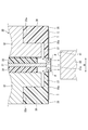
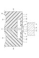
- the gap dimension W between the left and right protrusions 37 is set to a dimension in which the fastener element E engaged with the fastener chain C is fitted between the left and right protrusions 37.
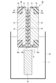
- the fastener chain C is wound around the first electrode part 30 and a current is passed through the first electrode 31 of the first electrode part 30, so that the current is supplied to the first electrode part 30.
- the fastener element E After flowing from 31 to the fastener element E, it flows to the left and right second electrodes 32 and the second electrode portion 40 of the first electrode portion 30 via the electrolytic solution L.
- both surfaces of the fastener element E (the surface on the second electrode 32 side and the second electrode portion) facing the first electrode (anode) 31 facing the left and right second electrodes 32 and the second electrode portion 40 that are the cathodes.
- the anionic electrodeposition paint is attracted to the surface 40), and a coating film of the electrolyte L is formed. And a coating film is continuously formed in the fastener element E by conveying the fastener chain C in the said state.
- the paint adheres not only to the front and back surfaces of the fastener element E but also to the side surfaces.
- Electrodeposition apparatus 10 Electrolysis tank 30 1st electrode part 31 1st electrode 31a 1st circular arc surface 32 2nd electrode 33 Insulating spacer 35 Guide member 35a 1st circular arc surface 40 2nd electrode part 41 2nd circular arc surface L Electrolyte C Fastener chain T Fastener tape E Fastener element
Landscapes
- Electroplating Methods And Accessories (AREA)
- Coating Apparatus (AREA)
Abstract
Description
(1)ファスナーチェーンの金属製のファスナーエレメントに電着塗装を施す電着塗装装置であって、水性塗料又は水溶性樹脂の電解液が貯留される電解槽と、電解槽内で互いに対向するように配置される第1電極部及び第2電極部と、を備え、ファスナーチェーンは、ファスナーエレメントの表裏面の一方が第1電極部に接触し、他方が第2電極部と間隔をあけて対向する状態で第1電極部と第2電極部との間を通過するように搬送されることを特徴とする電着塗装装置。
(2)ファスナーエレメントの表裏面の一方は、第1電極部と接触する領域と、電解液と接触する領域と、を有し、第1電極部と接触する領域は、電解液と接触する領域よりも小さいことを特徴とする(1)に記載の電着塗装装置。
(3)第2電極部と同じ極の電流が流れる第2電極が、ファスナーエレメントの第2電極部と対向する面と反対の面側に設けられることを特徴とする(1)又は(2)に記載の電着塗装装置。
(4)第1電極部は、ファスナーチェーンのファスナーエレメントと接触する板状の電極と、電極の軸方向両側に配置され、ファスナーチェーンのファスナーテープと接触して、ファスナーチェーンの搬送を案内する一対のガイド部材と、を備えることを特徴とする(3)に記載の電着塗装装置。
(5)第1電極部の電極及びガイド部材は、第2電極部に向かって凸状に設けられる第1円弧面を有し、第2電極部は、第1円弧面に対して一定の間隔を保持するように凹状に設けられる第2円弧面を有することを特徴とする(4)に記載の電着塗装装置。
(6)電極が円形状又は半円形状であり、ガイド部材が円形状又は半円形状であることを特徴とする(4)又は(5)に記載の電着塗装装置。
(7)第1電極部の電極は、第2電極部と異なる極の電流が流れる第1電極であり、第1電極部は、第1電極とガイド部材との間において、第1電極の軸方向両側に配置される一対の第2電極と、第1電極と一対の第2電極との間に配置される一対の絶縁スペーサと、を更に備えることを特徴とする(4)~(6)のいずれか1つに記載の電着塗装装置。
(8)第1電極及び第2電極は、同心に配置される円形状又は半円形状であり、第1電極の半径は、第2電極の半径よりも大きいことを特徴とする(7)に記載の電着塗装装置。
(9)電解液の液面は、ファスナーチェーンが第1電極部に接触する位置と同じか、その位置よりも下方に位置することを特徴とする(1)~(8)のいずれか1つに記載の電着塗装装置。
例えば、第1電極部は、円形状に形成されているが、これに限定されず、ファスナーチェーンが接触する部分のみ円弧形状であればよいため、半円形状に形成されていてもよい。
20 電解槽
30 第1電極部
31 第1電極
31a 第1円弧面
32 第2電極
33 絶縁スペーサ
35 ガイド部材
35a 第1円弧面
40 第2電極部
41 第2円弧面
L 電解液
C ファスナーチェーン
T ファスナーテープ
E ファスナーエレメント
Claims (9)
- ファスナーチェーン(C)の金属製のファスナーエレメント(E)に電着塗装を施す電着塗装装置(10)であって、
水性塗料又は水溶性樹脂の電解液(L)が貯留される電解槽(20)と、
前記電解槽(20)内で互いに対向するように配置される第1電極部(30)及び第2電極部(40)と、を備え、
前記ファスナーチェーン(C)は、前記ファスナーエレメント(E)の表裏面の一方が前記第1電極部(30)に接触し、他方が前記第2電極部(40)と間隔をあけて対向する状態で前記第1電極部(30)と前記第2電極部(40)との間を通過するように搬送されることを特徴とする電着塗装装置(10)。 - 前記ファスナーエレメント(E)の表裏面の一方は、前記第1電極部(30)と接触する領域と、前記電解液(L)と接触する領域と、を有し、
前記第1電極部(30)と接触する領域は、前記電解液(L)と接触する領域よりも小さいことを特徴とする請求項1に記載の電着塗装装置(10)。 - 前記第2電極部(40)と同じ極の電流が流れる第2電極(32)が、前記ファスナーエレメント(E)の前記第2電極部(40)と対向する面と反対の面側に設けられることを特徴とする請求項1又は2に記載の電着塗装装置(10)。
- 前記第1電極部(30)は、
前記ファスナーチェーン(C)の前記ファスナーエレメント(E)と接触する板状の電極(31)と、
前記電極(31)の軸方向両側に配置され、前記ファスナーチェーン(C)のファスナーテープ(T)と接触して、前記ファスナーチェーン(C)の搬送を案内する一対のガイド部材(35)と、を備えることを特徴とする請求項3に記載の電着塗装装置(10)。 - 前記第1電極部(30)の前記電極(31)及び前記ガイド部材(35)は、前記第2電極部(40)に向かって凸状に設けられる第1円弧面(31a,35a)を有し、
前記第2電極部(40)は、前記第1円弧面(31a,35a)に対して一定の間隔を保持するように凹状に設けられる第2円弧面(41)を有することを特徴とする請求項4に記載の電着塗装装置(10)。 - 前記電極(31)が円形状又は半円形状であり、
前記ガイド部材(35)が円形状又は半円形状であることを特徴とする請求項4又は5に記載の電着塗装装置(10)。 - 前記第1電極部(30)の前記電極(31)は、前記第2電極部(40)と異なる極の電流が流れる第1電極(31)であり、
前記第1電極部(30)は、
前記第1電極(31)と前記ガイド部材(35)との間において、前記第1電極(31)の軸方向両側に配置される一対の前記第2電極(32)と、
前記第1電極(31)と前記一対の第2電極(32)との間に配置される一対の絶縁スペーサ(33)と、を更に備えることを特徴とする請求項4~6のいずれか1項に記載の電着塗装装置(10)。 - 前記第1電極(31)及び前記第2電極(32)は、同心に配置される円形状又は半円形状であり、
前記第1電極(31)の半径は、前記第2電極(32)の半径よりも大きいことを特徴とする請求項7に記載の電着塗装装置(10)。 - 前記電解液(L)の液面は、前記ファスナーチェーン(C)が前記第1電極部(30)に接触する位置と同じか、その位置よりも下方に位置することを特徴とする請求項1~8のいずれか1項に記載の電着塗装装置(10)。
Priority Applications (5)
| Application Number | Priority Date | Filing Date | Title |
|---|---|---|---|
| BR112019018822-3A BR112019018822B1 (pt) | 2017-03-23 | 2017-03-23 | Dispositivo de revestimento por eletrodeposição |
| MX2019011073A MX2019011073A (es) | 2017-03-23 | 2017-03-23 | Dispositivo de recubrimiento por electrodeposicion. |
| PCT/JP2017/011881 WO2018173231A1 (ja) | 2017-03-23 | 2017-03-23 | 電着塗装装置 |
| CN201780088534.6A CN110431257B (zh) | 2017-03-23 | 2017-03-23 | 电沉积涂装装置 |
| TW106124988A TWI627920B (zh) | 2017-03-23 | 2017-07-26 | Electrodeposition coating device |
Applications Claiming Priority (1)
| Application Number | Priority Date | Filing Date | Title |
|---|---|---|---|
| PCT/JP2017/011881 WO2018173231A1 (ja) | 2017-03-23 | 2017-03-23 | 電着塗装装置 |
Publications (1)
| Publication Number | Publication Date |
|---|---|
| WO2018173231A1 true WO2018173231A1 (ja) | 2018-09-27 |
Family
ID=63584215
Family Applications (1)
| Application Number | Title | Priority Date | Filing Date |
|---|---|---|---|
| PCT/JP2017/011881 Ceased WO2018173231A1 (ja) | 2017-03-23 | 2017-03-23 | 電着塗装装置 |
Country Status (5)
| Country | Link |
|---|---|
| CN (1) | CN110431257B (ja) |
| BR (1) | BR112019018822B1 (ja) |
| MX (1) | MX2019011073A (ja) |
| TW (1) | TWI627920B (ja) |
| WO (1) | WO2018173231A1 (ja) |
Citations (3)
| Publication number | Priority date | Publication date | Assignee | Title |
|---|---|---|---|---|
| JPS4912098B1 (ja) * | 1969-10-31 | 1974-03-22 | ||
| JPH0219496A (ja) * | 1988-05-20 | 1990-01-23 | Mb Group Plc | 電解処理装置 |
| JP2008510068A (ja) * | 2004-08-13 | 2008-04-03 | ピーピージー インダストリーズ オハイオ, インコーポレイテッド | 搬送用連続ベルト上の物体をコーティングするための方法 |
Family Cites Families (5)
| Publication number | Priority date | Publication date | Assignee | Title |
|---|---|---|---|---|
| JP2003193293A (ja) * | 2001-12-28 | 2003-07-09 | Ykk Corp | スライドファスナーチェーンの務歯列における陽極酸化皮膜の形成方法とその装置 |
| CN100389232C (zh) * | 2003-12-21 | 2008-05-21 | 福建浔兴拉链科技股份有限公司 | 拉链链齿排的电镀装置 |
| JP2015021154A (ja) * | 2013-07-18 | 2015-02-02 | ペルメレック電極株式会社 | 電解金属箔の連続製造方法及び電解金属箔連続製造装置 |
| TWM483283U (zh) * | 2014-04-16 | 2014-08-01 | Chang-Wen Tsao | 連續滾動式電極鏈齒的電鍍裝置 |
| CN204959058U (zh) * | 2015-09-28 | 2016-01-13 | 庄冰梅 | 方便型拉链电镀装置 |
-
2017
- 2017-03-23 CN CN201780088534.6A patent/CN110431257B/zh active Active
- 2017-03-23 MX MX2019011073A patent/MX2019011073A/es unknown
- 2017-03-23 WO PCT/JP2017/011881 patent/WO2018173231A1/ja not_active Ceased
- 2017-03-23 BR BR112019018822-3A patent/BR112019018822B1/pt active IP Right Grant
- 2017-07-26 TW TW106124988A patent/TWI627920B/zh active
Patent Citations (3)
| Publication number | Priority date | Publication date | Assignee | Title |
|---|---|---|---|---|
| JPS4912098B1 (ja) * | 1969-10-31 | 1974-03-22 | ||
| JPH0219496A (ja) * | 1988-05-20 | 1990-01-23 | Mb Group Plc | 電解処理装置 |
| JP2008510068A (ja) * | 2004-08-13 | 2008-04-03 | ピーピージー インダストリーズ オハイオ, インコーポレイテッド | 搬送用連続ベルト上の物体をコーティングするための方法 |
Also Published As
| Publication number | Publication date |
|---|---|
| TW201834575A (zh) | 2018-10-01 |
| TWI627920B (zh) | 2018-07-01 |
| BR112019018822A2 (pt) | 2020-04-14 |
| MX2019011073A (es) | 2019-11-12 |
| BR112019018822B1 (pt) | 2023-05-02 |
| CN110431257A (zh) | 2019-11-08 |
| CN110431257B (zh) | 2021-10-08 |
Similar Documents
| Publication | Publication Date | Title |
|---|---|---|
| CN101678976B (zh) | 供电方法、供电装置、电解电镀装置及带电镀膜的连结板 | |
| US20110186423A1 (en) | Electroplating apparatus | |
| US20100170802A1 (en) | Power feeding method, continuous electrolytic plating apparatus for web and method for manufacturing plastic film with plated coating film | |
| US6991717B2 (en) | Web processing method and apparatus | |
| JP2019145420A (ja) | 電池極板の製造方法および塗工装置 | |
| CN110431257B (zh) | 电沉积涂装装置 | |
| CN112779578B (zh) | 一种超薄膜电镀装置 | |
| CA1234772A (en) | Method and apparatus for unilateral electroplating of a moving metal strip | |
| JP2015218008A (ja) | 塗工システム | |
| JP5667838B2 (ja) | 部分めっき方法および部分めっき装置 | |
| KR101993769B1 (ko) | 롤투롤 공정의 인쇄회로기판 수평 도금라인에서 캐소드롤러의 역 도금 방지 장치 | |
| CN210458392U (zh) | 一种用于电镀的走带装置 | |
| CN109706495A (zh) | 用于电镀的走带装置 | |
| CN110302940B (zh) | 涂布装置及涂布方法 | |
| TW202024402A (zh) | 鍍覆裝置及鍍覆方法 | |
| WO2013117269A1 (en) | Multi-wire plating line at various levels | |
| JP6024613B2 (ja) | 電気めっき装置 | |
| US20220010445A1 (en) | Circuit pattern continuous manufacturing device | |
| JP6578933B2 (ja) | ラジアルセル方式の電気めっき装置、及び電気めっきストリップの製造方法 | |
| JP2017080684A (ja) | 塗工装置 | |
| KR20250009087A (ko) | 피도금체에 균일 두께의 도금이 가능하도록 곡면 형상의 도금 전극을 갖는 도금 장치 | |
| JP2014227572A (ja) | 化学処理装置 | |
| CN117802554A (zh) | 电极板及带钢的钝化处理方法 | |
| JP2020050911A (ja) | めっき装置およびそれを用いためっき方法 | |
| JPH093691A (ja) | メッキ装置 |
Legal Events
| Date | Code | Title | Description |
|---|---|---|---|
| 121 | Ep: the epo has been informed by wipo that ep was designated in this application |
Ref document number: 17902152 Country of ref document: EP Kind code of ref document: A1 |
|
| NENP | Non-entry into the national phase |
Ref country code: DE |
|
| REG | Reference to national code |
Ref country code: BR Ref legal event code: B01A Ref document number: 112019018822 Country of ref document: BR |
|
| 122 | Ep: pct application non-entry in european phase |
Ref document number: 17902152 Country of ref document: EP Kind code of ref document: A1 |
|
| ENP | Entry into the national phase |
Ref document number: 112019018822 Country of ref document: BR Kind code of ref document: A2 Effective date: 20190911 |
|
| NENP | Non-entry into the national phase |
Ref country code: JP |