WO2018168854A1 - 自動二輪車用動力伝達システム - Google Patents
自動二輪車用動力伝達システム Download PDFInfo
- Publication number
- WO2018168854A1 WO2018168854A1 PCT/JP2018/009743 JP2018009743W WO2018168854A1 WO 2018168854 A1 WO2018168854 A1 WO 2018168854A1 JP 2018009743 W JP2018009743 W JP 2018009743W WO 2018168854 A1 WO2018168854 A1 WO 2018168854A1
- Authority
- WO
- WIPO (PCT)
- Prior art keywords
- continuously variable
- variable transmission
- engine
- way clutch
- inner body
- Prior art date
- Legal status (The legal status is an assumption and is not a legal conclusion. Google has not performed a legal analysis and makes no representation as to the accuracy of the status listed.)
- Ceased
Links
Images


Classifications
-
- B—PERFORMING OPERATIONS; TRANSPORTING
- B60—VEHICLES IN GENERAL
- B60K—ARRANGEMENT OR MOUNTING OF PROPULSION UNITS OR OF TRANSMISSIONS IN VEHICLES; ARRANGEMENT OR MOUNTING OF PLURAL DIVERSE PRIME-MOVERS IN VEHICLES; AUXILIARY DRIVES FOR VEHICLES; INSTRUMENTATION OR DASHBOARDS FOR VEHICLES; ARRANGEMENTS IN CONNECTION WITH COOLING, AIR INTAKE, GAS EXHAUST OR FUEL SUPPLY OF PROPULSION UNITS IN VEHICLES
- B60K17/00—Arrangement or mounting of transmissions in vehicles
- B60K17/04—Arrangement or mounting of transmissions in vehicles characterised by arrangement, location or kind of gearing
-
- B—PERFORMING OPERATIONS; TRANSPORTING
- B60—VEHICLES IN GENERAL
- B60K—ARRANGEMENT OR MOUNTING OF PROPULSION UNITS OR OF TRANSMISSIONS IN VEHICLES; ARRANGEMENT OR MOUNTING OF PLURAL DIVERSE PRIME-MOVERS IN VEHICLES; AUXILIARY DRIVES FOR VEHICLES; INSTRUMENTATION OR DASHBOARDS FOR VEHICLES; ARRANGEMENTS IN CONNECTION WITH COOLING, AIR INTAKE, GAS EXHAUST OR FUEL SUPPLY OF PROPULSION UNITS IN VEHICLES
- B60K6/00—Arrangement or mounting of plural diverse prime-movers for mutual or common propulsion, e.g. hybrid propulsion systems comprising electric motors and internal combustion engines
- B60K6/20—Arrangement or mounting of plural diverse prime-movers for mutual or common propulsion, e.g. hybrid propulsion systems comprising electric motors and internal combustion engines the prime-movers consisting of electric motors and internal combustion engines, e.g. HEVs
- B60K6/22—Arrangement or mounting of plural diverse prime-movers for mutual or common propulsion, e.g. hybrid propulsion systems comprising electric motors and internal combustion engines the prime-movers consisting of electric motors and internal combustion engines, e.g. HEVs characterised by apparatus, components or means specially adapted for HEVs
- B60K6/38—Arrangement or mounting of plural diverse prime-movers for mutual or common propulsion, e.g. hybrid propulsion systems comprising electric motors and internal combustion engines the prime-movers consisting of electric motors and internal combustion engines, e.g. HEVs characterised by apparatus, components or means specially adapted for HEVs characterised by the driveline clutches
- B60K6/383—One-way clutches or freewheel devices
-
- B—PERFORMING OPERATIONS; TRANSPORTING
- B60—VEHICLES IN GENERAL
- B60K—ARRANGEMENT OR MOUNTING OF PROPULSION UNITS OR OF TRANSMISSIONS IN VEHICLES; ARRANGEMENT OR MOUNTING OF PLURAL DIVERSE PRIME-MOVERS IN VEHICLES; AUXILIARY DRIVES FOR VEHICLES; INSTRUMENTATION OR DASHBOARDS FOR VEHICLES; ARRANGEMENTS IN CONNECTION WITH COOLING, AIR INTAKE, GAS EXHAUST OR FUEL SUPPLY OF PROPULSION UNITS IN VEHICLES
- B60K6/00—Arrangement or mounting of plural diverse prime-movers for mutual or common propulsion, e.g. hybrid propulsion systems comprising electric motors and internal combustion engines
- B60K6/20—Arrangement or mounting of plural diverse prime-movers for mutual or common propulsion, e.g. hybrid propulsion systems comprising electric motors and internal combustion engines the prime-movers consisting of electric motors and internal combustion engines, e.g. HEVs
- B60K6/22—Arrangement or mounting of plural diverse prime-movers for mutual or common propulsion, e.g. hybrid propulsion systems comprising electric motors and internal combustion engines the prime-movers consisting of electric motors and internal combustion engines, e.g. HEVs characterised by apparatus, components or means specially adapted for HEVs
- B60K6/40—Arrangement or mounting of plural diverse prime-movers for mutual or common propulsion, e.g. hybrid propulsion systems comprising electric motors and internal combustion engines the prime-movers consisting of electric motors and internal combustion engines, e.g. HEVs characterised by apparatus, components or means specially adapted for HEVs characterised by the assembly or relative disposition of components
-
- B—PERFORMING OPERATIONS; TRANSPORTING
- B60—VEHICLES IN GENERAL
- B60K—ARRANGEMENT OR MOUNTING OF PROPULSION UNITS OR OF TRANSMISSIONS IN VEHICLES; ARRANGEMENT OR MOUNTING OF PLURAL DIVERSE PRIME-MOVERS IN VEHICLES; AUXILIARY DRIVES FOR VEHICLES; INSTRUMENTATION OR DASHBOARDS FOR VEHICLES; ARRANGEMENTS IN CONNECTION WITH COOLING, AIR INTAKE, GAS EXHAUST OR FUEL SUPPLY OF PROPULSION UNITS IN VEHICLES
- B60K6/00—Arrangement or mounting of plural diverse prime-movers for mutual or common propulsion, e.g. hybrid propulsion systems comprising electric motors and internal combustion engines
- B60K6/20—Arrangement or mounting of plural diverse prime-movers for mutual or common propulsion, e.g. hybrid propulsion systems comprising electric motors and internal combustion engines the prime-movers consisting of electric motors and internal combustion engines, e.g. HEVs
- B60K6/50—Architecture of the driveline characterised by arrangement or kind of transmission units
- B60K6/54—Transmission for changing ratio
- B60K6/543—Transmission for changing ratio the transmission being a continuously variable transmission
-
- B—PERFORMING OPERATIONS; TRANSPORTING
- B62—LAND VEHICLES FOR TRAVELLING OTHERWISE THAN ON RAILS
- B62M—RIDER PROPULSION OF WHEELED VEHICLES OR SLEDGES; POWERED PROPULSION OF SLEDGES OR SINGLE-TRACK CYCLES; TRANSMISSIONS SPECIALLY ADAPTED FOR SUCH VEHICLES
- B62M23/00—Transmissions characterised by use of other elements; Other transmissions
- B62M23/02—Transmissions characterised by use of other elements; Other transmissions characterised by the use of two or more dissimilar sources of power, e.g. transmissions for hybrid motorcycles
-
- B—PERFORMING OPERATIONS; TRANSPORTING
- B62—LAND VEHICLES FOR TRAVELLING OTHERWISE THAN ON RAILS
- B62M—RIDER PROPULSION OF WHEELED VEHICLES OR SLEDGES; POWERED PROPULSION OF SLEDGES OR SINGLE-TRACK CYCLES; TRANSMISSIONS SPECIALLY ADAPTED FOR SUCH VEHICLES
- B62M9/00—Transmissions characterised by use of an endless chain, belt, or the like
Definitions
- the present invention relates to a power transmission system for a motorcycle.
- some motorcycles such as scooters transmit or block power from an engine using a centrifugal clutch (see, for example, Patent Document 1).
- the centrifugal clutch gradually transmits torque from the engine to the drive wheels in a half-clutch state, and then completely transmits torque from the engine to the drive wheels.
- An object of the present invention is to provide a power transmission system suitable for a hybrid or electric motorcycle.
- a motorcycle power transmission system includes an electric motor, drive wheels, a continuously variable transmission, and a two-way clutch.
- the continuously variable transmission changes the torque from the electric motor.
- the two-way clutch is disposed between the continuously variable transmission and the drive wheel.
- the two-way clutch is configured to transmit torque from the continuously variable transmission to the drive wheels and to block torque transmission from the drive wheels to the continuously variable transmission.
- the two-way clutch transmits the torque from the continuously variable transmission in the clutch engaged state without transmitting the torque from the continuously variable transmission in the half clutch state, thereby reducing the transmission loss of the torque from the continuously variable transmission to the drive wheels. can do.
- the two-way clutch blocks torque transmission from the drive wheels to the continuously variable transmission while the vehicle is stopped, so that it is easy to push and move the stopped motorcycle.
- the power transmission system for a motorcycle according to the present invention is suitable for a hybrid or electric motorcycle.
- the motorcycle power transmission system further includes a final gear disposed between the continuously variable transmission and the drive wheel, and the two-way clutch is disposed between the continuously variable transmission and the final gear.
- the motorcycle power transmission system further includes a final gear disposed between the continuously variable transmission and the driving wheel, and the two-way clutch is disposed between the driving wheel and the final gear.
- the continuously variable transmission is a belt type continuously variable transmission.
- the electric motor is driven by the engine to generate electric power and to start the engine.
- the motorcycle power transmission system further includes an engine.
- the continuously variable transmission changes the torque from the engine.
- a power transmission system suitable for a hybrid or electric motorcycle can be provided.
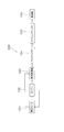
- FIG. 1 is a block diagram of a power transmission system for a motorcycle.
- the perspective view of a holder. The figure which shows the roller located in a neutral position.
- the block diagram of the power transmission system for motorcycles which concerns on a modification.
- the motorcycle power transmission system 200 includes an electric motor 101, an engine 102, a continuously variable transmission 103, a two-way clutch 100, a final gear 104, and drive wheels 105. .
- the electric motor 101 is one of the drive sources of the motorcycle according to this embodiment.
- the electric motor 101 rotationally drives the drive wheels 105 at the time of starting or sudden acceleration.
- the electric motor 101 is configured to start the engine 102. That is, the electric motor 101 is used as a cell motor when the engine 102 is started.
- the electric motor 101 is configured to be driven by the engine 102 to generate electric power. That is, the electric motor 101 is also used as a dynamo after the engine 102 is started.
- the engine 102 is one of the drive sources of the motorcycle according to this embodiment. That is, the motorcycle according to the present embodiment has two drive sources of the electric motor 101 and the engine 102.
- the engine 102 rotationally drives the drive wheels 105 during normal travel.
- the engine 102 rotates the drive wheels 105 and drives the electric motor 101 to generate electric power.
- the continuously variable transmission 103 is configured to shift torque from the electric motor 101 and the engine 102.
- the continuously variable transmission 103 is a belt type continuously variable transmission. That is, the motorcycle according to this embodiment employs an automatic transmission.
- the continuously variable transmission 103 receives torque from the electric motor 101 and the engine 102.
- the continuously variable transmission 103 includes a driving pulley device, a driven pulley device, and a belt.
- the belt is hung between the driving pulley device and the driven pulley device. As the diameter of each pulley device changes, the gear ratio changes continuously.
- the two-way clutch 100 is disposed between the continuously variable transmission 103 and the drive wheel 105. Specifically, the two-way clutch 100 is disposed between the continuously variable transmission 103 and the final gear 104. The two-way clutch 100 is configured to transmit torque from the continuously variable transmission 103 to the drive wheels 105 and to block transmission of torque from the drive wheels 105 to the continuously variable transmission 103 while the vehicle is stopped. Details of the two-way clutch 100 will be described later.
- the final gear 104 is disposed between the two-way clutch 100 and the drive wheel 105. Specifically, the final gear 104 is provided between a drive shaft (not shown) and the drive wheel 105. Examples of the final gear 104 include a three-axis reduction mechanism that combines a spur gear or a helical gear, and a one-axis reduction mechanism that uses a planetary gear.
- the drive wheels 105 are wheels that rotate by receiving torque from the electric motor 101 and the engine 102.
- the rear wheels are generally drive wheels 105.
- the motorcycle power transmission system 200 configured as described above operates as follows.
- the drive wheels 105 When starting and when traveling at low and medium speeds, the drive wheels 105 are driven by the electric motor 101. That is, torque from the electric motor 101 is transmitted to the drive wheels 105 via the continuously variable transmission 103, the two-way clutch 100, and the final gear 104.
- the drive wheels 105 are driven by torque from the engine 102. That is, torque from the engine 102 is transmitted to the drive wheels 105 via the continuously variable transmission 103, the two-way clutch 100, and the final gear 104.
- the electric motor 101 may be caused to generate electric power by the torque of the engine 102. That is, the electric motor 101 is caused to function as a dynamo.
- the electric power generated by the electric motor 101 is stored in a battery (not shown).
- the engine 102 is started by the electric motor 101. That is, the electric motor 101 functions as a cell motor.
- the two-way clutch 100 transmits the torque from the electric motor 101 and the engine 102 to the drive wheels 105. As will be described later, the two-way clutch 100 transmits torque from the electric motor 101 and the engine 102 to the drive wheels 105 during acceleration and deceleration.
- the axial direction means a direction in which the rotation shaft O of the two-way clutch extends.
- the radial direction means the radial direction of a circle around the rotation axis O
- the circumferential direction means the circumferential direction of the circle around the rotation axis O.
- the inner side in the radial direction means a side close to the rotation axis O in the radial direction
- the outer side in the radial direction means a side far from the rotation axis O in the radial direction.
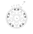
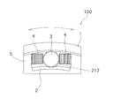
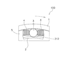
- the two-way clutch 100 includes an outer race 1, an inner body 2, a plurality of rollers 3, a plurality of pairs of urging members 4, a holder 5, and a cam mechanism 6.
- the outer race 1 is connected to the drive wheel 105 side
- the inner body 2 is connected to the electric motor 101 and the engine 102 side.
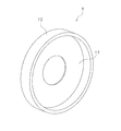
- the outer race 1 is cylindrical.
- the outer race 1 outputs torque to the drive wheel 105.
- the outer race 1 is rotatable around the rotation axis O.
- the outer race 1 is formed of, for example, carbon steel for machine structure, tool steel for machine structure, carbon tool steel, or alloy tool steel.
- the outer race 1 has a disc part 11 and a cylindrical part 12.
- the cylindrical portion 12 is cylindrical and extends in the axial direction from the outer peripheral edge of the disc portion 11.
- the tubular portion 12 constitutes the outer wall of the two-way clutch 100.
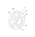
- the inner body 2 is disposed inside the outer race 1 in the radial direction. Specifically, the inner body 2 is disposed inside the cylindrical portion 12 of the outer race 1 in the radial direction. The inner body 2 is rotatable around the rotation axis O. Further, the inner body 2 can be rotated relative to the outer race 1. Torque from the electric motor 101 or the engine 102 is input to the inner body 2.
- the inner body 2 has an inner body main body portion 21 and a boss portion 22.
- the inner body 2 is formed of, for example, carbon steel for machine structure, tool steel for machine structure, carbon tool steel, or alloy tool steel.
- the inner body main body 21 has a disk shape.
- the outer peripheral surface 211 of the inner body main body 21 is disposed with a space from the inner peripheral surface of the outer race 1. In a state where the roller 3, the urging member 4, and the holder 5 are removed, the outer peripheral surface 211 of the inner body main body 21 faces the inner peripheral surface of the outer race 1.
- the inner peripheral surface of the outer race 1 means the inner peripheral surface of the tubular portion 12 of the outer race 1.
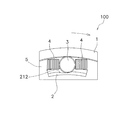
- a plurality of cam surfaces 212 are formed on the outer peripheral surface 211 of the inner body main body 21.
- the cam surfaces 212 are formed at intervals in the circumferential direction.
- the cam surfaces 212 are arranged at equal intervals in the circumferential direction.
- Each cam surface 212 is configured to be recessed inward in the radial direction.
- the central portion in the circumferential direction of the cam surface 212 is farthest from the inner peripheral surface of the outer race 1.
- Each cam surface 212 is configured to approach the outer race 1 as it approaches both ends in the circumferential direction.
- each cam surface 212 is formed in an arc shape when viewed in the axial direction.
- the inner body main body 21 has a plurality of first through holes 213.
- Each first through hole 213 penetrates the inner body main body 21 in the axial direction.
- the first through holes 213 are arranged at intervals in the circumferential direction.
- the first through holes 213 are arranged at equal intervals in the circumferential direction.
- Each first through hole 213 is arranged on the same circumference.
- Each first through-hole 213 has a long hole shape extending in the circumferential direction.
- the boss portion 22 has a cylindrical shape and extends from the inner body main body portion 21 in the axial direction.
- the boss portion 22 is arranged coaxially with the inner body main body portion 21.
- the boss portion 22 is configured to engage with an input shaft (not shown) to which torque from the electric motor 101 or the engine 102 side is input.
- the boss portion 22 has a second through hole 221.
- the second through hole 221 is configured to engage the input shaft.
- the second through hole 221 has a pair of opposed flat surfaces on the inner peripheral surface.
- the input shaft has a pair of planes facing each other on the outer peripheral surface. With this configuration, the input shaft engages with the second through hole 221 and can rotate integrally.
- the second through hole 221 penetrates not only the boss portion 22 but also the inner body main body portion 21.
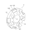
- the holder 5 holds each roller 3 and each biasing member 4.
- the holder 5 is disposed so as to be rotatable relative to the inner body 2.
- the holder 5 is made of resin, and can be specifically formed of PA resin, POM resin, PPS resin, PBT resin, PEEK resin, PTFE resin, or the like.
- the holder 5 is aligned with the inner body 2 in the axial direction.
- the holder 5 has a disc plate shape and has a third through hole 51 at the center thereof.
- the holder 5 has a holder main body portion 52 and a holding portion 53.
- the holder main body 52 is disk-shaped and has a third through hole 51 in the center.
- the third through hole 51 passes through the holder main body 52 in the axial direction.
- the third through-hole 51 is circular when viewed in the axial direction.
- the boss portion 22 of the inner body 2 passes through the third through hole 51 of the holder 5. That is, the boss 22 extends in the axial direction beyond the holder 5 via the third through hole 51.
- the outer diameter of the boss portion 22 is smaller than the inner diameter of the third through hole 51.
- the holder 5 is supported by the inner body 2 by the inner peripheral surface of the third through hole 51 coming into contact with the outer peripheral surface of the boss portion 22. Specifically, the upper end portion of the inner peripheral surface of the third through hole 51 and the upper end portion of the outer peripheral surface of the boss portion 22 are in contact with each other.
- the holder main body 52 has a plurality of fourth through holes 521.
- the fourth through holes 521 are arranged at intervals in the circumferential direction.
- the fourth through holes 521 are arranged at equal intervals in the circumferential direction.
- the holding portion 53 is configured to hold the roller 3 and the biasing member 4 in the circumferential direction.
- the holding portion 53 has a cylindrical shape and extends from the holder main body portion 52 in the axial direction.
- the holding portion 53 is disposed between the outer race 1 and the inner body 2 in the radial direction.
- the holding portion 53 is disposed between the cylindrical portion 12 of the outer race 1 and the inner body main body portion 21 of the inner body 2 in the radial direction.
- the holding part 53 has a plurality of fifth through holes 531.
- Each fifth through hole 531 penetrates the holding portion 53 in the radial direction. For this reason, the outer race 1 and the inner body 2 face each other through the fifth through hole 531 in a state where the roller 3 and the pair of biasing members 4 are removed.
- Each fifth through-hole 531 is arranged with a gap in the circumferential direction.
- the fifth through holes 531 are arranged at equal intervals in the circumferential direction.
- Each fifth through-hole 531 is composed of a pair of inner wall surfaces.
- the pair of inner wall surfaces constitute a holding surface 532.
- the pair of holding surfaces 532 face each other in the circumferential direction.
- the pair of holding surfaces 532 hold the roller 3 and the pair of urging members 4.
- roller 3 As shown in FIGS. 2 and 3, the roller 3 is held by a holder 5. Specifically, the roller 3 is held by the holder 5 via a pair of urging members 4. The roller 3 is disposed in the fifth through hole 531 of the holder 5.
- Each roller 3 has a cylindrical shape extending in the axial direction.
- the roller 3 is disposed between the outer race 1 and the inner body 2 in the radial direction.
- the roller 3 is disposed between the cylindrical portion 12 of the outer race 1 and the inner body main body portion 21 in the radial direction.
- the roller 3 can take a neutral position and a meshing position. As shown in FIG. 7, the neutral position means a position where the roller 3 does not mesh between the outer race 1 and the inner body 2. Specifically, when the roller 3 is located at the neutral position, the roller 3 is located at the center of the cam surface 212 in the circumferential direction.
- the meshing position means a position where the roller 3 is meshed between the outer race 1 and the inner body 2. Specifically, when the roller 3 is located at the meshing position, the roller 3 is located at a position moved from the central portion of the cam surface 212 to both end portions.
- each biasing member 4 has a first end and a second end. The first end portion that contacts the roller 3 is disposed on the inner side in the radial direction than the second end portion that contacts the holding surface 532.
- Each urging member 4 is held by a holder 5.
- the urging member 4 may be, for example, a leaf spring or a coil spring.
- the cam mechanism 6 is configured to engage the roller 3 between the outer race 1 and the inner body 2 when the inner body 2 rotates relative to the holder 5. Specifically, the cam mechanism 6 has a cam surface 212 formed on the outer peripheral surface of the inner body 2.
- the two-way clutch 100 configured as described above operates as follows. First, in a state where no torque is input from a drive source such as the electric motor 101 or the engine 102, the roller 3 is positioned at the neutral position as shown in FIG. That is, the roller 3 is located at the center of the cam surface 212 and is not meshed between the outer race 1 and the inner body 2. For this reason, for example, when it is desired to push and move a stopped motorcycle, even if the driving wheel 105 rotates by pushing the motorcycle, only the outer race 1 rotates and the inner body 2 does not rotate. The motor 101 or the engine 102 is not rotated. That is, the two-way clutch 100 blocks torque transmission from the drive wheels 105 to the continuously variable transmission 103. As a result, the motorcycle can be easily moved. Note that the arrows in FIG. 7 indicate the rotation direction of the outer race 1.
- the inner body 2 rotates.
- the rotation speed of the holder 5 is slower than that of the inner body 2 due to inertia
- the inner body 2 and the holder 5 rotate relatively.
- the roller 3 moves from the neutral position to the meshing position, and the roller 3 meshes between the outer race 1 and the inner body 2.
- the outer race 1 and the inner body 2 rotate integrally. That is, torque is transmitted from the inner body 2 to the outer race 1 via each roller 3. Therefore, the two-way clutch 100 transmits the torque from the continuously variable transmission 103 to the drive wheels 105.
- the arrows in FIG. 8 indicate the rotation direction of the two-way clutch 100.
- the holder 5 rotates faster than the inner body 2 due to inertia during deceleration, the inner body 2 and the holder 5 rotate relatively. Then, as shown in FIG. 9, the roller 3 moves from the neutral position to the meshing position, and the roller 3 meshes between the outer race 1 and the inner body 2. As a result, the outer race 1 and the inner body 2 rotate integrally. That is, torque is transmitted from the inner body 2 to the outer race 1 via each roller 3. Therefore, the two-way clutch 100 transmits the torque from the continuously variable transmission 103 to the drive wheels 105.
- the arrows in FIG. 9 indicate the direction of rotation of the two-way clutch 100.
- the inner body 2 and the holder 5 are relatively rotated by the inertia of the holder 5.
- the roller 3 meshes between the outer race 1 and the inner body 2, and torque from the electric motor 101 or the engine 102 is transmitted to the drive wheels 105.
- the holder main body 52 of the holder 5 has a disk-like plate shape extending from the boss 22 to the outer race 1.
- the contact point between the inner body 2 and the holder 5 is set to the inner side in the radial direction. Bring it to. Specifically, the boss portion 22 of the inner body 2 is brought into contact with the inner peripheral surface of the third through hole 51 of the holder 5.
- the two-way clutch 100 is disposed between the continuously variable transmission 103 and the final gear 104, but the arrangement of the two-way clutch 100 is not limited to this.
- the two-way clutch 100 may be disposed between the drive wheel 105 and the final gear 104.
- the cam surface 212 is formed in an arc shape when viewed in the axial direction, but the cam surface 212 may be formed in a V shape or other shapes. May be.
- the input shaft for inputting torque from the engine to the inner body 2 and the second through hole 221 of the boss portion 22 may be engaged by spline fitting or other structures. Good.
- the inner body main body 21 may not have the first through hole 213.
- the holder 5 may not have the fourth through hole 521.
- the motorcycle power transmission system is applied to the hybrid motorcycle.
- the hybrid motorcycle may be applied to an electric motorcycle.
Landscapes
- Engineering & Computer Science (AREA)
- Chemical & Material Sciences (AREA)
- Combustion & Propulsion (AREA)
- Transportation (AREA)
- Mechanical Engineering (AREA)
- Hybrid Electric Vehicles (AREA)
- Arrangement Of Transmissions (AREA)
Applications Claiming Priority (2)
| Application Number | Priority Date | Filing Date | Title |
|---|---|---|---|
| JP2017-049772 | 2017-03-15 | ||
| JP2017049772A JP6892766B2 (ja) | 2017-03-15 | 2017-03-15 | 自動二輪車用動力伝達システム |
Publications (1)
| Publication Number | Publication Date |
|---|---|
| WO2018168854A1 true WO2018168854A1 (ja) | 2018-09-20 |
Family
ID=63523172
Family Applications (1)
| Application Number | Title | Priority Date | Filing Date |
|---|---|---|---|
| PCT/JP2018/009743 Ceased WO2018168854A1 (ja) | 2017-03-15 | 2018-03-13 | 自動二輪車用動力伝達システム |
Country Status (2)
| Country | Link |
|---|---|
| JP (1) | JP6892766B2 (enExample) |
| WO (1) | WO2018168854A1 (enExample) |
Citations (5)
| Publication number | Priority date | Publication date | Assignee | Title |
|---|---|---|---|---|
| JPH11255176A (ja) * | 1998-03-16 | 1999-09-21 | Yamaha Motor Co Ltd | 電動二輪車 |
| JP2005001410A (ja) * | 2003-06-09 | 2005-01-06 | Honda Motor Co Ltd | ハイブリッド車両 |
| JP2005104242A (ja) * | 2003-09-29 | 2005-04-21 | Honda Motor Co Ltd | ハイブリッド車両 |
| CN101157374A (zh) * | 2007-10-30 | 2008-04-09 | 西安交通大学 | 一种混合动力摩托车 |
| GB2487933A (en) * | 2011-02-08 | 2012-08-15 | Scion Sprays Ltd | Hybrid drive system |
Family Cites Families (3)
| Publication number | Priority date | Publication date | Assignee | Title |
|---|---|---|---|---|
| KR100258784B1 (ko) * | 1998-01-20 | 2000-06-15 | 마재열 | 자전거허브의 정,역구동 변환장치 |
| EP1036957B1 (en) * | 1999-03-18 | 2001-12-05 | Liau, Bai-Guang | Power transmission system employing a motor and an engine |
| JP2001008314A (ja) * | 1999-06-15 | 2001-01-12 | Yamaha Motor Co Ltd | 電動車両の駆動制御装置 |
-
2017
- 2017-03-15 JP JP2017049772A patent/JP6892766B2/ja active Active
-
2018
- 2018-03-13 WO PCT/JP2018/009743 patent/WO2018168854A1/ja not_active Ceased
Patent Citations (5)
| Publication number | Priority date | Publication date | Assignee | Title |
|---|---|---|---|---|
| JPH11255176A (ja) * | 1998-03-16 | 1999-09-21 | Yamaha Motor Co Ltd | 電動二輪車 |
| JP2005001410A (ja) * | 2003-06-09 | 2005-01-06 | Honda Motor Co Ltd | ハイブリッド車両 |
| JP2005104242A (ja) * | 2003-09-29 | 2005-04-21 | Honda Motor Co Ltd | ハイブリッド車両 |
| CN101157374A (zh) * | 2007-10-30 | 2008-04-09 | 西安交通大学 | 一种混合动力摩托车 |
| GB2487933A (en) * | 2011-02-08 | 2012-08-15 | Scion Sprays Ltd | Hybrid drive system |
Also Published As
| Publication number | Publication date |
|---|---|
| JP2018150020A (ja) | 2018-09-27 |
| JP6892766B2 (ja) | 2021-06-23 |
Similar Documents
| Publication | Publication Date | Title |
|---|---|---|
| TW201446584A (zh) | 無段變速器、與電馬達耦合的使用此無段變速器的系統以及人力驅動機器 | |
| WO2012096308A1 (ja) | モータ駆動力伝達装置 | |
| JP6792585B2 (ja) | 動力伝達装置、及び自動二輪車 | |
| WO2013069098A1 (ja) | 車両用動力伝達装置 | |
| KR101675383B1 (ko) | 아이들 제어가 가능한 듀얼 일방향 클러치 및 이를 구비한 변속기 | |
| KR20160036050A (ko) | 토크 캠 장치 및 벨트식 무단 변속 장치 | |
| JP2011220509A (ja) | 2方向クラッチ及び車両の駆動装置 | |
| WO2018168854A1 (ja) | 自動二輪車用動力伝達システム | |
| JP2014190364A (ja) | 鞍乗り型車両の動力伝達装置 | |
| JP2010018101A (ja) | ハイブリッド車両の駆動力伝達装置 | |
| JP2009078754A (ja) | ハイブリッド車両における駆動力伝達装置の制御方法 | |
| JP7151967B2 (ja) | 駆動装置およびそれを備える車両 | |
| KR101344376B1 (ko) | 능동형 자동 변속기 | |
| CN107128170B (zh) | 车辆用动力传递装置 | |
| JP6791591B2 (ja) | トルクカム装置及び無段変速機 | |
| KR101552179B1 (ko) | 무단변속기 | |
| WO2018168851A1 (ja) | クラッチ装置 | |
| JP5942877B2 (ja) | ベルト式無段変速機の制御装置 | |
| JP2012247042A (ja) | 駆動装置 | |
| JP3167161U (ja) | 無段変速装置 | |
| JP6575377B2 (ja) | 無段変速装置 | |
| JP2012161239A (ja) | モータ駆動力伝達装置 | |
| JP7093258B2 (ja) | トルクベクタリング装置 | |
| JP2020005441A (ja) | 駆動用電動機及び電動車両 | |
| JP2025006875A (ja) | デファレンシャル装置 |
Legal Events
| Date | Code | Title | Description |
|---|---|---|---|
| 121 | Ep: the epo has been informed by wipo that ep was designated in this application |
Ref document number: 18768578 Country of ref document: EP Kind code of ref document: A1 |
|
| NENP | Non-entry into the national phase |
Ref country code: DE |
|
| 122 | Ep: pct application non-entry in european phase |
Ref document number: 18768578 Country of ref document: EP Kind code of ref document: A1 |