WO2018168131A1 - トリガースイッチ - Google Patents
トリガースイッチ Download PDFInfo
- Publication number
- WO2018168131A1 WO2018168131A1 PCT/JP2017/044734 JP2017044734W WO2018168131A1 WO 2018168131 A1 WO2018168131 A1 WO 2018168131A1 JP 2017044734 W JP2017044734 W JP 2017044734W WO 2018168131 A1 WO2018168131 A1 WO 2018168131A1
- Authority
- WO
- WIPO (PCT)
- Prior art keywords
- terminal
- housing
- electric wire
- trigger switch
- wire connection
- Prior art date
- Legal status (The legal status is an assumption and is not a legal conclusion. Google has not performed a legal analysis and makes no representation as to the accuracy of the status listed.)
- Ceased
Links
Images

Classifications
-
- H—ELECTRICITY
- H01—ELECTRIC ELEMENTS
- H01R—ELECTRICALLY-CONDUCTIVE CONNECTIONS; STRUCTURAL ASSOCIATIONS OF A PLURALITY OF MUTUALLY-INSULATED ELECTRICAL CONNECTING ELEMENTS; COUPLING DEVICES; CURRENT COLLECTORS
- H01R9/00—Structural associations of a plurality of mutually-insulated electrical connecting elements, e.g. terminal strips or terminal blocks; Terminals or binding posts mounted upon a base or in a case; Bases therefor
- H01R9/22—Bases, e.g. strip, block, panel
- H01R9/223—Insulating enclosures for terminals
-
- H—ELECTRICITY
- H01—ELECTRIC ELEMENTS
- H01H—ELECTRIC SWITCHES; RELAYS; SELECTORS; EMERGENCY PROTECTIVE DEVICES
- H01H1/00—Contacts
- H01H1/58—Electric connections to or between contacts; Terminals
- H01H1/5844—Electric connections to or between contacts; Terminals making use of wire-gripping clips or springs
-
- H—ELECTRICITY
- H01—ELECTRIC ELEMENTS
- H01H—ELECTRIC SWITCHES; RELAYS; SELECTORS; EMERGENCY PROTECTIVE DEVICES
- H01H13/00—Switches having rectilinearly-movable operating part or parts adapted for pushing or pulling in one direction only, e.g. push-button switch
- H01H13/02—Details
- H01H13/04—Cases; Covers
-
- B—PERFORMING OPERATIONS; TRANSPORTING
- B25—HAND TOOLS; PORTABLE POWER-DRIVEN TOOLS; MANIPULATORS
- B25F—COMBINATION OR MULTI-PURPOSE TOOLS NOT OTHERWISE PROVIDED FOR; DETAILS OR COMPONENTS OF PORTABLE POWER-DRIVEN TOOLS NOT PARTICULARLY RELATED TO THE OPERATIONS PERFORMED AND NOT OTHERWISE PROVIDED FOR
- B25F5/00—Details or components of portable power-driven tools not particularly related to the operations performed and not otherwise provided for
-
- H—ELECTRICITY
- H01—ELECTRIC ELEMENTS
- H01H—ELECTRIC SWITCHES; RELAYS; SELECTORS; EMERGENCY PROTECTIVE DEVICES
- H01H1/00—Contacts
- H01H1/58—Electric connections to or between contacts; Terminals
- H01H1/5866—Electric connections to or between contacts; Terminals characterised by the use of a plug and socket connector
-
- H—ELECTRICITY
- H01—ELECTRIC ELEMENTS
- H01H—ELECTRIC SWITCHES; RELAYS; SELECTORS; EMERGENCY PROTECTIVE DEVICES
- H01H13/00—Switches having rectilinearly-movable operating part or parts adapted for pushing or pulling in one direction only, e.g. push-button switch
- H01H13/02—Details
- H01H13/10—Bases; Stationary contacts mounted thereon
-
- H—ELECTRICITY
- H01—ELECTRIC ELEMENTS
- H01H—ELECTRIC SWITCHES; RELAYS; SELECTORS; EMERGENCY PROTECTIVE DEVICES
- H01H13/00—Switches having rectilinearly-movable operating part or parts adapted for pushing or pulling in one direction only, e.g. push-button switch
- H01H13/02—Details
- H01H13/12—Movable parts; Contacts mounted thereon
- H01H13/14—Operating parts, e.g. push-button
-
- H—ELECTRICITY
- H01—ELECTRIC ELEMENTS
- H01H—ELECTRIC SWITCHES; RELAYS; SELECTORS; EMERGENCY PROTECTIVE DEVICES
- H01H9/00—Details of switching devices, not covered by groups H01H1/00 - H01H7/00
- H01H9/02—Bases, casings, or covers
- H01H9/06—Casing of switch constituted by a handle serving a purpose other than the actuation of the switch, e.g. by the handle of a vacuum cleaner
-
- H—ELECTRICITY
- H01—ELECTRIC ELEMENTS
- H01R—ELECTRICALLY-CONDUCTIVE CONNECTIONS; STRUCTURAL ASSOCIATIONS OF A PLURALITY OF MUTUALLY-INSULATED ELECTRICAL CONNECTING ELEMENTS; COUPLING DEVICES; CURRENT COLLECTORS
- H01R12/00—Structural associations of a plurality of mutually-insulated electrical connecting elements, specially adapted for printed circuits, e.g. printed circuit boards [PCB], flat or ribbon cables, or like generally planar structures, e.g. terminal strips, terminal blocks; Coupling devices specially adapted for printed circuits, flat or ribbon cables, or like generally planar structures; Terminals specially adapted for contact with, or insertion into, printed circuits, flat or ribbon cables, or like generally planar structures
- H01R12/70—Coupling devices
- H01R12/91—Coupling devices allowing relative movement between coupling parts, e.g. floating or self aligning
-
- H—ELECTRICITY
- H01—ELECTRIC ELEMENTS
- H01R—ELECTRICALLY-CONDUCTIVE CONNECTIONS; STRUCTURAL ASSOCIATIONS OF A PLURALITY OF MUTUALLY-INSULATED ELECTRICAL CONNECTING ELEMENTS; COUPLING DEVICES; CURRENT COLLECTORS
- H01R13/00—Details of coupling devices of the kinds covered by groups H01R12/70 or H01R24/00 - H01R33/00
- H01R13/02—Contact members
- H01R13/20—Pins, blades, or sockets shaped, or provided with separate member, to retain co-operating parts together
-
- H—ELECTRICITY
- H01—ELECTRIC ELEMENTS
- H01R—ELECTRICALLY-CONDUCTIVE CONNECTIONS; STRUCTURAL ASSOCIATIONS OF A PLURALITY OF MUTUALLY-INSULATED ELECTRICAL CONNECTING ELEMENTS; COUPLING DEVICES; CURRENT COLLECTORS
- H01R13/00—Details of coupling devices of the kinds covered by groups H01R12/70 or H01R24/00 - H01R33/00
- H01R13/40—Securing contact members in or to a base or case; Insulating of contact members
- H01R13/42—Securing in a demountable manner
- H01R13/428—Securing in a demountable manner by resilient locking means on the contact members; by locking means on resilient contact members
-
- H—ELECTRICITY
- H01—ELECTRIC ELEMENTS
- H01R—ELECTRICALLY-CONDUCTIVE CONNECTIONS; STRUCTURAL ASSOCIATIONS OF A PLURALITY OF MUTUALLY-INSULATED ELECTRICAL CONNECTING ELEMENTS; COUPLING DEVICES; CURRENT COLLECTORS
- H01R13/00—Details of coupling devices of the kinds covered by groups H01R12/70 or H01R24/00 - H01R33/00
- H01R13/40—Securing contact members in or to a base or case; Insulating of contact members
- H01R13/42—Securing in a demountable manner
- H01R13/428—Securing in a demountable manner by resilient locking means on the contact members; by locking means on resilient contact members
- H01R13/432—Securing in a demountable manner by resilient locking means on the contact members; by locking means on resilient contact members by stamped-out resilient tongue snapping behind shoulder in base or case
-
- H—ELECTRICITY
- H01—ELECTRIC ELEMENTS
- H01R—ELECTRICALLY-CONDUCTIVE CONNECTIONS; STRUCTURAL ASSOCIATIONS OF A PLURALITY OF MUTUALLY-INSULATED ELECTRICAL CONNECTING ELEMENTS; COUPLING DEVICES; CURRENT COLLECTORS
- H01R13/00—Details of coupling devices of the kinds covered by groups H01R12/70 or H01R24/00 - H01R33/00
- H01R13/62—Means for facilitating engagement or disengagement of coupling parts or for holding them in engagement
- H01R13/629—Additional means for facilitating engagement or disengagement of coupling parts, e.g. aligning or guiding means, levers, gas pressure electrical locking indicators, manufacturing tolerances
- H01R13/631—Additional means for facilitating engagement or disengagement of coupling parts, e.g. aligning or guiding means, levers, gas pressure electrical locking indicators, manufacturing tolerances for engagement only
- H01R13/6315—Additional means for facilitating engagement or disengagement of coupling parts, e.g. aligning or guiding means, levers, gas pressure electrical locking indicators, manufacturing tolerances for engagement only allowing relative movement between coupling parts, e.g. floating connection
-
- H—ELECTRICITY
- H01—ELECTRIC ELEMENTS
- H01R—ELECTRICALLY-CONDUCTIVE CONNECTIONS; STRUCTURAL ASSOCIATIONS OF A PLURALITY OF MUTUALLY-INSULATED ELECTRICAL CONNECTING ELEMENTS; COUPLING DEVICES; CURRENT COLLECTORS
- H01R9/00—Structural associations of a plurality of mutually-insulated electrical connecting elements, e.g. terminal strips or terminal blocks; Terminals or binding posts mounted upon a base or in a case; Bases therefor
- H01R9/16—Fastening of connecting parts to base or case; Insulating connecting parts from base or case
-
- H—ELECTRICITY
- H01—ELECTRIC ELEMENTS
- H01H—ELECTRIC SWITCHES; RELAYS; SELECTORS; EMERGENCY PROTECTIVE DEVICES
- H01H13/00—Switches having rectilinearly-movable operating part or parts adapted for pushing or pulling in one direction only, e.g. push-button switch
- H01H13/02—Details
- H01H13/04—Cases; Covers
- H01H13/08—Casing of switch constituted by a handle serving a purpose other than the actuation of the switch
-
- H—ELECTRICITY
- H01—ELECTRIC ELEMENTS
- H01H—ELECTRIC SWITCHES; RELAYS; SELECTORS; EMERGENCY PROTECTIVE DEVICES
- H01H9/00—Details of switching devices, not covered by groups H01H1/00 - H01H7/00
- H01H9/02—Bases, casings, or covers
- H01H9/06—Casing of switch constituted by a handle serving a purpose other than the actuation of the switch, e.g. by the handle of a vacuum cleaner
- H01H2009/065—Battery operated hand tools in which the battery and the switch are directly connected
-
- H—ELECTRICITY
- H01—ELECTRIC ELEMENTS
- H01H—ELECTRIC SWITCHES; RELAYS; SELECTORS; EMERGENCY PROTECTIVE DEVICES
- H01H2207/00—Connections
- H01H2207/026—Pressure contact
-
- H—ELECTRICITY
- H01—ELECTRIC ELEMENTS
- H01R—ELECTRICALLY-CONDUCTIVE CONNECTIONS; STRUCTURAL ASSOCIATIONS OF A PLURALITY OF MUTUALLY-INSULATED ELECTRICAL CONNECTING ELEMENTS; COUPLING DEVICES; CURRENT COLLECTORS
- H01R4/00—Electrically-conductive connections between two or more conductive members in direct contact, i.e. touching one another; Means for effecting or maintaining such contact; Electrically-conductive connections having two or more spaced connecting locations for conductors and using contact members penetrating insulation
- H01R4/28—Clamped connections, spring connections
- H01R4/30—Clamped connections, spring connections utilising a screw or nut clamping member
- H01R4/34—Conductive members located under head of screw
Definitions
- This disclosure relates to a trigger switch.
- the trigger switch disclosed in Patent Document 1 includes a housing, a trigger that is provided outside the housing and connected to the housing so as to be capable of approaching and separating, and a trigger that is provided inside the housing.
- a contact mechanism portion that operates in conjunction with the operation and the opening operation, and a pair of screw-type power connection terminals that are electrically connected to the contact mechanism portion are provided.
- each power connection terminal is provided on the housing, fixed to the outer surface of the housing and connected to the electric wire, and disposed inside the housing and connected to the contact mechanism. It consists of a terminal part.
- An object of the present disclosure is to provide a trigger switch capable of reducing the size of the housing.
- the trigger switch includes: A housing having an accommodating portion therein; A trigger provided outside the housing and connected to the housing so as to be close and open; A fixed contact provided in the housing portion, and is provided to face the fixed contact in the housing portion, and contacts the fixed contact in conjunction with an approach operation and a release operation of the trigger with respect to the housing.
- a contact mechanism having a movable contact to be opened, A plate-like first terminal fixed to the housing, extending from the outside of the housing to the accommodating portion, and electrically connected to the contact mechanism portion; A plate that is fixed to the housing, extends from the outside of the housing to the housing portion, is arranged in parallel so that the first terminal faces the plate surface, and is electrically connected to the contact mechanism portion; A second terminal having a shape, A first electric wire connecting portion capable of connecting a conductor portion of the first electric wire is provided at an end portion of the first terminal located outside the housing in the extending direction of the first terminal, and the second terminal extends. A second electric wire connecting portion capable of connecting a conductor portion of the second electric wire is provided at an end portion of the second terminal located outside the housing in the current direction.
- the first wire connecting portion capable of connecting the conductor portion of the first wire is provided at the end portion of the first terminal located outside the housing in the extending direction of the first terminal
- a second electric wire connecting portion capable of connecting a conductor portion of the second electric wire is provided at an end portion of the second terminal located outside the housing in the extending direction of the second terminal.
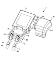
- the perspective view of the trigger switch of one embodiment of this indication The perspective view which shows the state which attached the crimp terminal to the 1st electric wire connection part and 2nd electric wire connection part of the trigger switch of FIG.
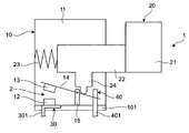
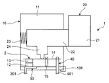
- the schematic diagram for demonstrating the reset state of the trigger switch of FIG. The schematic diagram for demonstrating the operation state of the trigger switch of FIG.
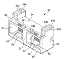
- the perspective view of the terminal cover member of the trigger switch of FIG. The perspective view seen from the direction different from FIG. 5 of the terminal cover member of the trigger switch of FIG.
- the trigger switch 1 includes an insulating housing 10, an insulating trigger 20, a conductive first terminal 30, and a conductive second terminal 40. ing.
- the first terminal 30 and the second terminal 40 extend downward (that is, downward in FIG. 1) from the lower end portion (that is, the lower end portion of FIG. 1) of the housing 10, respectively.
- the first electric wire connecting portion 31 is provided at the tip of the first terminal 30 located outside the housing 10 in the direction in which the first terminal 30 extends (that is, the extending direction), and the housing 10 in the direction in which the second terminal 40 extends.
- the 2nd electric wire connection part 41 is provided in the front-end
- the 1st electric wire connection part 31 and the 2nd electric wire connection part 41 are accommodated in the insulating terminal cover member 50 which has a box shape as an example, and as shown in FIG. Is fixed by a screw 62.
- the first electric wire connection portion 31 and the second electric wire connection portion 41 are connected to the conductor portion 64 of the first electric wire and the conductor portion 65 of the second electric wire via the crimp terminal 61, respectively.
- a housing part 11 is provided inside the housing 10, and the first terminal 30 and the second terminal 40 are electrically connected in the housing part 11.
- the contact mechanism portion 2 is provided.
- the housing 10 has a substantially rectangular parallelepiped box shape as shown in FIG.
- a trigger 20 that is connected to the housing 10 so as to be able to approach and separate from the housing 10 is disposed outside the housing 10.
- the contact mechanism unit 2 has a fixed contact 12 and a movable contact 13 as shown in FIGS. 3 and 4.
- 3 and 4 schematically show the trigger switch 1 with a part of the housing 10 removed.
- 3 shows the trigger switch 1 in a return state in which the fixed contact 12 and the movable contact 13 are separated
- FIG. 4 shows the trigger switch 1 in an operation state in which the fixed contact 12 and the movable contact 13 are in contact. ing.
- the fixed contact 12 is fixed to the conductive first terminal 30 inside the accommodating portion 11 and is electrically connected to the first terminal 30.
- the first terminal 30 includes a plate-like first terminal main body 301 extending from the outside of the housing 10 to the accommodating portion 11, and a first electric wire connecting portion 31 provided on the first terminal main body 301.
- the one-terminal body 301 is located on the lower side of the housing 10 (that is, in FIGS. It is fixed to the end of the wall portion 101 on the lower side in the Z direction far from the trigger 20.
- the first wire connecting portion 31 has a substantially square shape in plan view along the plate width direction of the first terminal body 301 (that is, the Y direction in FIG. 1).
- the first electric wire connecting portion 31 is one first of a pair of first side surfaces 303 and second side surfaces 304 facing in the plate width direction of the end portion 302 located outside the housing 10 of the first terminal body 301. It is disposed on the side surface 303 (that is, the surface on the left side in the Y direction in FIG. 1), and extends in a direction that intersects (for example, substantially orthogonal) to the plate surface of the first terminal body 301 and approaches the second terminal 40.
- the movable contact 13 is fixed to the movable contact piece 14 inside the accommodating portion 11 and is electrically connected to the conductive second terminal 40 via the movable contact piece 14.
- the movable contact 13 is disposed so as to face the fixed contact 12 and to be able to contact and separate from the fixed contact 12.
- the movable contact piece 14 has a long thin plate shape extending in the contact / separation direction of the trigger 20 and is rotatably supported by the support portion 15 at an intermediate portion in the longitudinal direction.
- the support portion 15 is provided substantially at the center of the wall portion 101 of the housing 10 in the contact / separation direction of the trigger 20.
- the movable contact 13 is fixed to one end of the movable contact piece 14 in the longitudinal direction (that is, the left end in FIGS. 3 and 4). Further, the other end portion in the longitudinal direction of the movable contact piece 14 (that is, the right end portion in FIGS. 3 and 4) is in contact with the second terminal 40.
- the second terminal 40 includes a plate-like second terminal main body 401 extending from the outside of the housing 10 to the accommodating portion 11, and a second electric wire connecting portion 41 provided on the second terminal main body 401.
- the two-terminal body 401 is fixed to the end portion of the lower wall portion 101 of the housing 10 in the contact / separation direction of the trigger 20, and is electrically independent of the first terminal 30.
- the second terminal body 401 is arranged in parallel so that the first terminal body 301 and the plate surfaces face each other.
- the second wire connecting portion 41 has a substantially square shape in plan view along the plate width direction (that is, the Y direction in FIG. 1) of the second terminal main body 401, and has a central shape in FIG. A circular through hole 42 into which a screw 62 shown in FIG.
- the second electric wire connecting portion 41 is one first of a pair of first side surface 403 and second side surface 404 that face each other in the plate width direction of the end portion 402 located outside the housing 10 of the second terminal main body 401. It is disposed on the side surface 403 (that is, the surface on the left side in the Y direction in FIG. 1), and extends in a direction that intersects (for example, substantially orthogonal) to the plate surface of the second terminal body 401 and approaches the first terminal 30.
- the trigger 20 is arranged on one side of the housing 10 in the short direction (that is, the left-right direction in FIGS. 3 and 4), and the operating body 21 that the user operates with a finger And an operating shaft 22 extending from the surface of the operating body 21 facing the housing 10 toward the inside of the housing 10 toward the housing 10.
- the operating body 21 has a curved surface 211 (shown in FIG. 1) on a surface far from the housing 10 in the contact / separation direction of the trigger 20, and makes it easy to operate the operating body 21 with a user's finger. .
- the operating shaft 22 is connected to the operating body 21 at one end in the extending direction (that is, the left-right direction in FIGS. 3 and 4) outside the housing 10.
- the other end in the extending direction is movably connected to the housing 10 inside the housing portion 11 of the housing 10.
- a return spring 23 that urges the operation shaft 22 in a direction for separating the trigger 20 from the housing 10 is provided.
- the operation shaft 22 is provided with a plunger 24 extending from the operation shaft 22 toward the wall portion 101 of the housing 10 inside the housing portion 11.
- the plunger 24 is arranged so that its tip (that is, the lower end in FIGS. 3 and 4) can contact the movable contact piece 14 in conjunction with the movement of the trigger 20.
- the movable contact 13 contacts and separates from the fixed contact 12 in conjunction with the approach operation and the separation operation of the trigger 20 as follows.
- the trigger 20 of the trigger switch 1 in the return state shown in FIG. 3 When the operation body 21 of the trigger 20 of the trigger switch 1 in the return state shown in FIG. 3 is operated to bring the trigger 20 closer to the housing 10, the trigger 20 moves in the approaching direction with respect to the housing 10 (that is, an approaching operation).
- the plunger 24 comes into contact with the movable contact piece 14 on the first terminal 30 side with respect to the support portion 15, and the movable contact piece 14 is moved in the direction of the rotation axis of the movable contact piece 14 (that is, FIGS.
- the sheet is rotated counterclockwise in a plan view along (through-paper direction).
- the movable contact 13 approaches the lower wall portion 101 of the housing 10 and comes into contact with the fixed contact 12 to be in the operation state shown in FIG.
- the operating shaft 22 is urged by the return spring 23 in a direction to release the trigger 20 from the housing 10. It moves away from the housing 10.
- the plunger 24 contacts the movable contact piece 14 on the second terminal 40 side with respect to the support portion 15 in conjunction with the movement of the trigger 20 in the opening direction with respect to the housing 10 (that is, the opening operation).
- the piece 14 is rotated clockwise in plan view along the rotation axis direction of the movable contact piece 14.
- the movable contact 13 is separated from the lower wall portion 101 of the housing 10 and the movable contact 13 is separated from the fixed contact 12 to be in the return state shown in FIG.
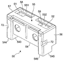
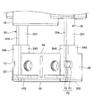
- the terminal cover member 50 has a substantially rectangular parallelepiped shape, and houses a first housing portion 51 for housing the first wire connecting portion 31 and a second wire connecting portion 41 therein. And a second accommodating portion 52.
- the crimp terminals 61 are respectively housed in the first housing portion 51 and the second housing portion 52, and the crimp terminals 61 are connected to the first wire connecting portion 31 and the second wire connecting portion 41 together with the screws 62 shown in FIG. 2.
- the nut 63 to be fixed is shown.
- the terminal cover member 50 includes a partition wall 53 that electrically insulates the first storage 51 and the second storage 52 by partitioning the first storage 51 and the second storage 52, and the partition.
- the second side wall 57 is disposed on the opposite side of the partition wall 53 from the first side wall 56.
- the partition wall portion 53 extends in the extending direction of the first terminal body 301 and the second terminal body 401, and extends in the extending direction of the partition wall portion 53 (that is, the vertical direction in FIGS. 5 and 6).
- the terminal cover member 50 is provided at the center in the longitudinal direction.
- the terminal insertion surface 54 is connected to the end portion closer to the housing 10 in the extending direction of the partition wall portion 53 (that is, the upper side in FIG. 5), and has a rectangular shape as shown in FIG.
- the terminal insertion surface 54 includes a first terminal insertion opening 541 into which the first electric wire connection portion 31 can be inserted, and a second terminal insertion opening 542 into which the second electric wire connection portion 41 can be inserted.
- Each of the first terminal insertion opening 541 and the second terminal insertion opening 542 has a substantially L shape extending along the longitudinal direction and the short direction of the terminal insertion surface 54. They are arranged symmetrically.
- the first terminal main body 301 can be inserted into a portion of the first terminal insertion opening 541 extending in the longitudinal direction of the terminal insertion surface 54, and the short direction of the terminal insertion surface 54 of the first terminal insertion opening 541
- the first electric wire connecting portion 31 can be inserted into the portion extending in the direction.
- the second terminal main body 401 can be inserted into a portion extending in the longitudinal direction of the terminal insertion surface 54 of the second terminal insertion opening 542, and the terminal insertion surface 54 of the second terminal insertion opening 542 can be inserted.
- the second electric wire connecting portion 41 can be inserted into a portion extending in the short direction. That is, the terminal insertion surface 54 extends in a direction intersecting with the partition wall portion 53, so that the first wire connection portion 31 can be inserted into the first housing portion 51 and the second wire connection portion 41 is inserted into the second housing portion 52. It is configured to be possible.
- the electric wire connection surface 55 is connected to an end portion far from the housing 10 in the extending direction of the partition wall portion 53 (that is, the lower side in FIG. 5), and has a rectangular shape as shown in FIG. .
- the electric wire connection surface 55 includes a first electric wire connection opening 551 into which the conductor portion 64 of the first electric wire can be inserted, and a second electric wire connection opening 552 into which the conductor portion 65 of the second electric wire can be inserted. Yes. That is, the electric wire connection surface 55 extends in a direction intersecting the partition wall portion 53 and is disposed to face the terminal insertion surface 54, and the conductor portion 64 of the first electric wire can be connected to the first electric wire connection portion 31. And the conductor part 65 of the 2nd electric wire is comprised so that connection to the 2nd electric wire connection part 41 is possible.
- Each of the first wire connection opening 551 and the second wire connection opening 552 has an L shape extending along the longitudinal direction and the short direction of the terminal insertion surface 54, and Are arranged symmetrically.
- the 1st electric wire connection opening part 551 is partially comprised by the 1st support wall part 58 mentioned later, and is inserted into the inside of the 1st accommodating part 51 from the 1st terminal insertion opening part 541.
- the terminal main body 301 and the first electric wire connecting portion 31 are configured not to move through the electric wire connecting surface 55 and to the outside of the terminal cover member 50.
- a part of the second electric wire connection opening 552 is constituted by a second support wall 59 described later, and the second electric wire connection opening 552 is inserted into the second accommodating part 52 from the second terminal insertion opening 542.
- the two-terminal main body 401 and the second electric wire connecting portion 41 are configured not to move through the electric wire connecting surface 55 to the outside of the terminal cover member 50.
- the first side wall portion 56 faces the second terminal main body 401 among the pair of plate surfaces of the first terminal main body 301 inserted into the first accommodating portion 51 from the first terminal insertion opening 541 of the terminal insertion surface 54. It guides along the direction which cross
- the second side wall 57 is opposed to the first terminal main body 301 among the pair of plate surfaces of the second terminal main body 401 inserted into the second accommodating portion 52 from the second terminal insertion opening 542 of the terminal insertion surface 54. It guides along the direction which cross
- the electric wire connection surface 55 is provided with a first support wall portion 58 and a second support wall portion 59 each extending along the electric wire connection surface 55.
- the second support wall 59 is disposed on the opposite side of the partition wall 53 from the first support wall 58.
- the first support wall 58 constitutes a part of the first electric wire connection opening 551, and the first terminal inserted into the first accommodating part 51 from the first terminal insertion opening 541 of the terminal insertion surface 54.
- the front end portion of the main body 301 and the front end portion of the first electric wire connecting portion 31 are provided so as to be able to come into contact with each other inside the first accommodating portion 51. That is, the first terminal body 301 and the first electric wire connection portion 31 inserted from the first terminal insertion opening 541 are supported and positioned by the first support wall portion 58 inside the first housing portion 51.
- the second support wall 59 constitutes a part of the second electric wire connection opening 552 and the second terminal inserted into the second accommodating part 52 from the second terminal insertion opening 542 of the terminal insertion surface 54.
- the front end portion of the main body 401 and the front end portion of the second electric wire connection portion 41 are provided so as to be able to come into contact with each other inside the second housing portion 52. That is, the second terminal main body 401 and the second electric wire connection portion 41 inserted from the second terminal insertion opening 542 are supported and positioned by the second support wall portion 59 inside the second housing portion 52.
- the first electric wire connecting portion 31 capable of connecting the conductor portion 64 of the first electric wire to the end portion 302 of the first terminal 30 located outside the housing 10 in the extending direction of the first terminal 30 is provided.
- a second electric wire connecting portion 41 that can be connected to the conductor portion 65 of the second electric wire is provided at an end portion 402 of the second terminal 40 that is provided and located outside the housing in the extending direction of the second terminal 40.
- an insulating terminal cover member 50 having a first housing part 51 for housing the first wire connection part 31 and a second housing part 52 for housing the second wire connection part 41 is further provided.
- the terminal cover member 50 extends from the terminal insertion surface 54 along the plate surface of the first terminal body 301 toward the housing 10 and supports a pair of first terminals that support the first terminal body 301.
- the pair of first terminal support walls 543 are connected by a first connection wall portion 544 that supports the second side surface 304 of the first terminal body 301 (that is, the surface on the right side in the Y direction in FIG. 1).
- the pair of second terminal support walls 545 are connected by a second connection wall portion 546 that supports the second side surface 404 of the second terminal body 401 (that is, the surface on the right side in the Y direction in FIG. 1). ing.
- the pair of first terminal support walls 543 are provided on both sides of the first terminal body 301 in the plate thickness direction, and are located outside the housing 10 and outside the terminal cover member 50.
- the base 305 on the terminal cover member 50 side in the first terminal main body 301 is supported.
- the pair of second terminal support walls 545 are provided on both sides of the second terminal main body 401 in the plate thickness direction, respectively, and are terminals in the second terminal main body 401 located outside the housing 10 and outside the terminal cover member 50.
- the base 405 on the cover member 50 side is supported.
- the bases 305 and 405 tend to concentrate stress.
- the base parts 305 and 405 are reinforced. 1 lifespan can be extended.
- the trigger switch 1 includes a snap fit portion 70 that can be detachably attached to the first terminal 30 and the second terminal 40 while positioning the terminal cover member 50.
- the snap fit portions 70 are provided on the pair of engaging claws 71 (only one is shown in FIG. 7) and the corresponding engaging claws provided on the first side wall portion 56 and the second side wall portion 57 of the terminal cover member 50, respectively. It is comprised with a pair of engagement hole 72 which can latch the part 71.
- the pair of engaging claws 71 are formed on the outer plate surfaces of the end portions 302 and 402 located outside the housing 10 of the first terminal body 301 and the second terminal body 401 (that is, the first side walls of the first terminal body 301). And a surface facing the second side wall portion 57 of the second terminal body 401).
- the engaging claw portion 71 of the first terminal main body 301 is disposed so as to be engageable with the engaging hole 72 of the opposing first side wall portion 56 in a state where the first electric wire connecting portion 31 is accommodated in the first accommodating portion 51.
- the engaging claw portion 71 of the second terminal main body 401 can be engaged with the engaging hole 72 of the second side wall portion 57 facing the second electric wire connecting portion 41 in the state where the second electric wire connecting portion 41 is accommodated in the second accommodating portion 52. Is arranged.
- the terminal cover member 50 can be detachably attached to the first terminal 30 and the second terminal 40 by the snap fit portion 70, the assembly of the trigger switch 1 is facilitated. Productivity can be improved.
- terminal cover member 50 may be omitted if possible.
- first terminal support walls 543 and the pair of second terminal support walls 545 may be provided.
- terminal cover member 50 is not limited to being attached to the first terminal 30 and the second terminal 40 by the snap fit portion 70.
- the attachment structure of the terminal cover member 50 to the first terminal 30 and the second terminal 40 can employ any structure depending on the design of the trigger switch, including whether or not the terminal cover member 50 is detachable.
- the trigger switch 1 includes: A housing 10 having an accommodating portion 11 therein; A trigger 20 provided outside the housing 10 and connected to the housing 10 so as to be close and open; The fixed contact 12 provided in the housing portion 11 is provided so as to face the fixed contact 12 in the housing portion 11, and the trigger 20 is moved toward and away from the housing 10.
- a contact mechanism portion 2 having a movable contact 13 that contacts and separates the fixed contact 12 in conjunction with each other;
- a plate-like first terminal 30 fixed to the housing 10 and extending from the outside of the housing 10 to the accommodating portion 11 and electrically connected to the contact mechanism portion 2;
- the housing 10 is fixed to the housing 10 and extends from the outside of the housing 10 to the accommodating portion 11.
- the first terminal 30 and the plate surfaces are arranged in parallel so as to face each other.
- a plate-like second terminal 40 connected to A first electric wire connecting portion 31 capable of connecting a conductor portion 64 of the first electric wire is provided at an end portion 302 of the first terminal 30 located outside the housing 10 in the extending direction of the first terminal 30;
- a second wire connecting portion 41 capable of connecting the conductor portion 65 of the second wire is provided at the end portion 402 of the second terminal 40 located outside the housing 10 in the extending direction of the second terminal 40.
- the housing 10 can be reduced in size as compared with the trigger switch in which the electric wire connecting portion is provided in the housing, and the electric tool can be reduced in size and weight.
- the trigger switch 1 of the second aspect of the present disclosure is: An insulating terminal cover member 50 having a first housing part 51 for housing the first wire connection part 31 and a second housing part 52 for housing the second wire connection part 41 is further provided outside the housing 10;
- the terminal cover member 50 is The first housing part 51 and the second housing part 52 are separated by extending in the extending direction of the first terminal 30 and the second terminal 40 to partition the first housing part 51 and the second housing part 52.
- the first electric wire connecting portion 31 and the second electric wire connecting portion 41 can be insulated with a simple configuration, and the first electric wire connecting portion 31 can be easily used as the conductor portion 64 of the first electric wire.
- the second electric wire connecting portion 41 can be easily connected to the conductor portion 65 of the second electric wire.
- the trigger switch 1 of the third aspect of the present disclosure is:
- the terminal cover member 50 is A first terminal support wall 543 that extends from the electric wire connection surface 55 along the plate surface of the first terminal 30 toward the housing 10 and supports the first terminal 30;
- a second terminal support wall 545 that extends from the wire connection surface 55 along the plate surface of the second terminal 40 toward the housing 10 and supports the second terminal 40.
- the stress concentration of the first terminal 30 and the second terminal 40 can be supported, so that the life of the trigger switch 1 can be extended.
- the trigger switch 1 of the fourth aspect of the present disclosure is:
- the first terminal support walls 543 are provided on both sides of the first terminal 30 in the plate thickness direction, and the second terminal support walls 545 are respectively provided on both sides of the second terminal 40 in the plate thickness direction. Is provided.
- the life of the trigger switch 1 can be extended more reliably.
- the trigger switch 1 of the fifth aspect of the present disclosure is: A snap fit portion 70 detachably attachable while positioning the terminal cover member 50 with respect to the first terminal 30 and the second terminal 40;
- the snap-fit portion 70 is provided on the terminal cover member 50 and a pair of engaging claw portions 71 provided at the ends of the first terminal 30 and the second terminal 40 that are located outside the housing 10. And a pair of engaging holes 72 that can respectively lock the pair of engaging claws 71.
- the assembly of the trigger switch 1 is facilitated, and the productivity of the trigger switch 1 can be improved.
- the trigger switch of the present disclosure can be applied to an electric tool such as an electric screwdriver, for example.
Landscapes
- Engineering & Computer Science (AREA)
- Mechanical Engineering (AREA)
- Physics & Mathematics (AREA)
- Electromagnetism (AREA)
- Switch Cases, Indication, And Locking (AREA)
- Push-Button Switches (AREA)
- Portable Power Tools In General (AREA)
Abstract
収容部を有するハウジングと、ハウジングに対して接近および開離可能に連結されたトリガーと、収容部内に設けられた接点機構部と、ハウジングの外部から収容部まで延びている板状の第1端子と、ハウジングの外部から収容部まで延びていると共に第1端子と板面同士が対向するように並列に配置された板状の第2端子とを備える。ハウジングの外部に位置する第1端子の端部に、第1電線の導体部を接続可能な第1電線接続部が設けられ、ハウジングの外部に位置する第2端子の端部に、第2電線の導体部を接続可能な第2電線接続部が設けられている。
Description
本開示は、トリガースイッチに関する。
特許文献1に開示されているトリガースイッチは、ハウジングと、ハウジングの外部に設けられかつハウジングに対して接近および開離可能に連結されたトリガーと、ハウジングの内部に設けられ、ハウジングに対するトリガーの接近動作および開離動作に連動して作動する接点機構部と、接点機構部に電気的に接続された一対のねじ式の電源接続端子とを備えている。
前記トリガースイッチでは、各電源接続端子は、ハウジングに設けられていると共に、ハウジングの外面上に固定されて電線が接続される接続部と、ハウジングの内部に配置されて接点機構部に接続された端子部とで構成されている。
近年、電動ドライバーなどの電動具の小型軽量化に伴って、特に、電動具に使用されるトリガースイッチのハウジングの収容スペースが制限される場合が増えている。しかし、前記トリガースイッチでは、一対の電源接続端子がハウジングに設けられているので、ハウジングの小型化を図るのが難しく、電動具の小型軽量化に対応できない場合がある。
本開示は、ハウジングの小型化を図ることができるトリガースイッチを提供することを課題とする。
本開示の一態様のトリガースイッチは、
内部に収容部を有するハウジングと、
前記ハウジングの外部に設けられ、前記ハウジングに対して接近および開離可能に連結されたトリガーと、
前記収容部内に設けられた固定接点と、前記収容部内で前記固定接点に対向するように設けられていると共に、前記ハウジングに対する前記トリガーの接近動作および開離動作に連動して前記固定接点に接触および開離する可動接点とを有する接点機構部と、
前記ハウジングに固定され、前記ハウジングの外部から前記収容部まで延びていると共に、前記接点機構部に電気的に接続されている板状の第1端子と、
前記ハウジングに固定され、前記ハウジングの外部から前記収容部まで延びていると共に、前記第1端子と板面同士が対向するように並列に配置され、前記接点機構部に電気的に接続された板状の第2端子と
を備え、
前記第1端子の延在方向における前記ハウジングの外部に位置する前記第1端子の端部に、第1電線の導体部を接続可能な第1電線接続部が設けられ、前記第2端子の延在方向における前記ハウジングの外部に位置する前記第2端子の端部に、第2電線の導体部を接続可能な第2電線接続部が設けられている。
内部に収容部を有するハウジングと、
前記ハウジングの外部に設けられ、前記ハウジングに対して接近および開離可能に連結されたトリガーと、
前記収容部内に設けられた固定接点と、前記収容部内で前記固定接点に対向するように設けられていると共に、前記ハウジングに対する前記トリガーの接近動作および開離動作に連動して前記固定接点に接触および開離する可動接点とを有する接点機構部と、
前記ハウジングに固定され、前記ハウジングの外部から前記収容部まで延びていると共に、前記接点機構部に電気的に接続されている板状の第1端子と、
前記ハウジングに固定され、前記ハウジングの外部から前記収容部まで延びていると共に、前記第1端子と板面同士が対向するように並列に配置され、前記接点機構部に電気的に接続された板状の第2端子と
を備え、
前記第1端子の延在方向における前記ハウジングの外部に位置する前記第1端子の端部に、第1電線の導体部を接続可能な第1電線接続部が設けられ、前記第2端子の延在方向における前記ハウジングの外部に位置する前記第2端子の端部に、第2電線の導体部を接続可能な第2電線接続部が設けられている。
前記態様のトリガースイッチによれば、第1端子の延在方向におけるハウジングの外部に位置する第1端子の端部に、第1電線の導体部を接続可能な第1電線接続部が設けられ、第2端子の延在方向におけるハウジングの外部に位置する第2端子の端部に、第2電線の導体部を接続可能な第2電線接続部が設けられている。これにより、例えば、ハウジングに電線接続部が設けられているトリガースイッチと比べて、ハウジングで電線接続部が占めるスペースを省略してハウジングの小型化を図ることができ、電動具の小型軽量化に対応できる。
以下、本開示の一実施形態を添付図面に従って説明する。なお、以下の説明では、必要に応じて特定の方向あるいは位置を示す用語(例えば、「上」、「下」、「右」、「左」を含む用語)を用いるが、それらの用語の使用は図面を参照した開示の理解を容易にするためであって、それらの用語の意味によって本開示の技術的範囲が限定されるものではない。また、以下の説明は、本質的に例示に過ぎず、本開示、その適用物、あるいは、その用途を制限することを意図するものではない。さらに、図面は模式的なものであり、各寸法の比率等は現実のものとは必ずしも合致していない。
本開示の一実施形態のトリガースイッチ1は、図1に示すように、絶縁性のハウジング10、絶縁性のトリガー20、導電性の第1端子30、および、導電性の第2端子40を備えている。
第1端子30および第2端子40は、それぞれ、ハウジング10の下端部(すなわち、図1の下端部)から下方(すなわち、図1の下向き)に延びている。第1端子30が延びる方向(すなわち、延在方向)におけるハウジング10の外部に位置する第1端子30の先端部に第1電線接続部31が設けられ、第2端子40が延びる方向におけるハウジング10の外部に位置する第2端子40の先端部に第2電線接続部41が設けられている。
この実施形態では、一例として、第1電線接続部31および第2電線接続部41は、箱形状を有する絶縁性の端子カバー部材50に収容されており、図2に示すように、圧着端子61がねじ62で固定されるようになっている。第1電線接続部31および第2電線接続部41は、それぞれ、圧着端子61を介して第1電線の導体部64および第2電線の導体部65に接続される。
また、ハウジング10の内部には、図3および図4に示すように、収容部11が設けられており、この収容部11内には、第1端子30および第2端子40と電気的に接続された接点機構部2が設けられている。
ハウジング10は、図1に示すように、略直方体の箱状を有している。また、ハウジング10の外部には、ハウジング10に対して接近および開離可能に連結されたトリガー20が配置されている。
接点機構部2は、図3および図4に示すように、固定接点12と可動接点13とを有している。なお、図3および図4は、ハウジング10の一部を取り除いた状態のトリガースイッチ1を模式的に示している。また、図3は、固定接点12と可動接点13とが開離した復帰状態のトリガースイッチ1を示し、図4は、固定接点12と可動接点13とが接触した動作状態のトリガースイッチ1を示している。
固定接点12は、収容部11の内部で導電性の第1端子30に固定され、第1端子30に電気的に接続されている。
第1端子30は、ハウジング10の外部から収容部11まで延びている板状の第1端子本体301と、この第1端子本体301に設けられた第1電線接続部31とを有し、第1端子本体301が、トリガー20がハウジング10に対して接近および開離する接離方向(すなわち、図3および図4の左右方向)において、ハウジング10の下側(すなわち、図3および図4のZ方向下側)の壁部101のトリガー20から遠い方の端部に固定されている。
第1電線接続部31は、図1に示すように、第1端子本体301の板幅方向(すなわち、図1のY方向)沿い平面視において、略正方形状を有し、その中央に図2に示すねじ62を挿入可能な円形状の貫通孔32が設けられている。この第1電線接続部31は、第1端子本体301のハウジング10の外部に位置する端部302の板幅方向に対向する一対の第1側面303および第2側面304のうちの一方の第1側面303(すなわち、図1のY方向左側の面)に配置され、第1端子本体301の板面に対して交差(例えば略直交)しかつ第2端子40に接近する方向に延びている。
可動接点13は、収容部11の内部で可動接触片14に固定され、可動接触片14を介して導電性の第2端子40に電気的に接続されている。可動接点13は、固定接点12に対向しかつ固定接点12に対して接触および開離可能に配置されている。
可動接触片14は、トリガー20の接離方向に延びる長尺の薄板形状を有し、その長手方向の中間部で支持部15に回動可能に支持されている。支持部15は、トリガー20の接離方向におけるハウジング10の壁部101の略中央に設けられている。可動接触片14の長手方向の一端部(すなわち、図3および図4の左側端部)には、可動接点13が固定されている。また、可動接触片14の長手方向の他端部(すなわち、図3および図4の右側端部)は第2端子40と接触している。
第2端子40は、ハウジング10の外部から収容部11まで延びている板状の第2端子本体401と、この第2端子本体401に設けられた第2電線接続部41とを有し、第2端子本体401が、トリガー20の接離方向において、ハウジング10の下側の壁部101のトリガー20に近い方の端部に固定され、第1端子30に対して電気的に独立している。また、第2端子本体401は、第1端子本体301と板面同士が対向するように並列に配置されている。
第2電線接続部41は、図1に示すように、第2端子本体401の板幅方向(すなわち、図1のY方向)沿い平面視において、略正方形状を有し、その中央に図2に示すねじ62を挿入可能な円形状の貫通孔42が設けられている。この第2電線接続部41は、第2端子本体401のハウジング10の外部に位置する端部402の板幅方向に対向する一対の第1側面403および第2側面404のうちの一方の第1側面403(すなわち、図1のY方向左側の面)に配置され、第2端子本体401の板面に対して交差(例えば略直交)しかつ第1端子30に接近する方向に延びている。
トリガー20は、図3および図4に示すように、ハウジング10の短手方向(すなわち、図3および図4の左右方向)の一側に配置され、使用者が指で操作する操作体21と、この操作体21のハウジング10に対向する面からハウジング10に向かってハウジング10の内部まで延びている操作軸22とを有している。
操作体21は、トリガー20の接離方向におけるハウジング10から遠い方の面に湾曲面211(図1に示す)を有しており、使用者の指により操作体21を操作し易くしている。
操作軸22は、図3および図4に示すように、その延在方向(すなわち、図3および図4の左右方向)の一端部がハウジング10の外部で操作体21に連結されている一方、その延在方向の他端部がハウジング10の収容部11の内部でハウジング10に移動可能に連結されている。操作軸22の延在方向の他端部には、トリガー20をハウジング10から開離させる方向に操作軸22を付勢する復帰ばね23が設けられている。
また、操作軸22には、収容部11の内部で操作軸22からハウジング10の壁部101に向かって延びるプランジャ24が設けられている。このプランジャ24は、トリガー20の移動に連動して、その先端(すなわち、図3および図4の下端)が、可動接触片14に接触可能に配置されている。
すなわち、可動接点13は、トリガー20の接近動作および開離動作に対して、次のように連動して、固定接点12に対して接触および開離する。
図3に示す復帰状態のトリガースイッチ1のトリガー20の操作体21を操作して、トリガー20をハウジング10に接近させると、トリガー20のハウジング10に対する接近方向への移動(すなわち、接近動作)に連動して、プランジャ24が、支持部15よりも第1端子30側で可動接触片14に接触して、可動接触片14を可動接触片14の回動軸方向(すなわち、図3および図4の紙面貫通方向)に沿った平面視において反時計回りに回動させる。これにより、可動接点13が、ハウジング10の下側の壁部101に接近して固定接点12に接触し、図4に示す動作状態となる。
図4に示す動作状態のトリガースイッチ1のトリガー20の操作体21から指を離すと、復帰ばね23により操作軸22が、トリガー20をハウジング10から開離させる方向に付勢され、トリガー20がハウジング10から開離する方向に移動する。このトリガー20のハウジング10に対する開離方向への移動(すなわち、開離動作)に連動して、プランジャ24が、支持部15に対する第2端子40側で可動接触片14に接触して、可動接触片14を可動接触片14の回動軸方向に沿った平面視において時計回りに回動させる。これにより、可動接点13が,ハウジング10の下側の壁部101から離れて可動接点13が固定接点12から開離し、図3に示す復帰状態となる。
端子カバー部材50は、図5および図6に示すように、略直方体状で、その内部に、第1電線接続部31を収容する第1収容部51と、第2電線接続部41を収容する第2収容部52とを有している。なお、図5では、第1収容部51および第2収容部52の内部にそれぞれ収容されて、図2に示すねじ62と共に第1電線接続部31および第2電線接続部41に圧着端子61を固定するナット63を示している。
詳しくは、端子カバー部材50は、第1収容部51および第2収容部52を仕切ることにより第1収容部51と第2収容部52とを電気的に絶縁する仕切壁部53と、この仕切壁部53に交差(例えば略直交)する方向に延びる端子挿入面54および電線接続面55と、仕切壁部53に対向して配置されている第1側壁部56および第2側壁部57とを有している。第2側壁部57は、仕切壁部53に対して第1側壁部56とは反対側に配置されている。
仕切壁部53は、第1端子本体301および第2端子本体401の延在方向に延びており、この仕切壁部53の延在方向(すなわち、図5および図6の上下方向)に沿って見たときに、端子カバー部材50の長手方向における中央部に設けられている。
端子挿入面54は、仕切壁部53の延在方向におけるハウジング10に近い方の端部(すなわち、図5の上側)に接続され、図5に示すように、矩形状を有している。この端子挿入面54は、第1電線接続部31を挿入可能な第1端子挿入開口部541と、第2電線接続部41を挿入可能な第2端子挿入開口部542とを有している。
第1端子挿入開口部541および第2端子挿入開口部542の各々は、端子挿入面54の長手方向および短手方向に沿ってそれぞれ延びる略L字形状を有しており、仕切壁部53に対して対称に配置されている。第1端子挿入開口部541の端子挿入面54の長手方向に延びる部分には、第1端子本体301が挿入可能になっており、第1端子挿入開口部541の端子挿入面54の短手方向に延びる部分には、第1電線接続部31が挿入可能になっている。同様に、第2端子挿入開口部542の端子挿入面54の長手方向に延びる部分には、第2端子本体401が挿入可能になっており、第2端子挿入開口部542の端子挿入面54の短手方向に延びる部分には、第2電線接続部41が挿入可能になっている。すなわち、端子挿入面54は、仕切壁部53に交差する方向に延びて、第1電線接続部31が第1収容部51に挿入可能かつ第2電線接続部41が第2収容部52に挿入可能に構成されている。
電線接続面55は、仕切壁部53の延在方向におけるハウジング10から遠い方の端部(すなわち、図5の下側)に接続され、図6に示すように、矩形状を有している。この電線接続面55は、第1電線の導体部64を挿入可能な第1電線接続開口部551と、第2電線の導体部65を挿入可能な第2電線接続開口部552とを有している。すなわち、電線接続面55は、仕切壁部53に交差する方向に延びかつ端子挿入面54に対向して配置されていると共に、第1電線の導体部64を第1電線接続部31に接続可能かつ第2電線の導体部65を第2電線接続部41に接続可能に構成されている。
第1電線接続開口部551および第2電線接続開口部552の各々は、端子挿入面54の長手方向および短手方向に沿ってそれぞれ延びるL字形状を有しており、仕切壁部53に対して対称に配置されている。
なお、第1電線接続開口部551は、その一部が後述する第1支持壁部58で構成されており、第1端子挿入開口部541から第1収容部51の内部に挿入された第1端子本体301および第1電線接続部31が、電線接続面55を突き抜けて端子カバー部材50の外部にまで移動しないように構成されている。同様に、第2電線接続開口部552は、その一部が後述する第2支持壁部59で構成されており、第2端子挿入開口部542から第2収容部52の内部に挿入された第2端子本体401および第2電線接続部41が、電線接続面55を突き抜けて端子カバー部材50の外部にまで移動しないように構成されている。
第1側壁部56は、端子挿入面54の第1端子挿入開口部541から第1収容部51に挿入された第1端子本体301の一対の板面のうち、第2端子本体401に対向していない外側の板面を支持しつつ端子挿入面54に交差する方向に沿って案内する。
第2側壁部57は、端子挿入面54の第2端子挿入開口部542から第2収容部52に挿入された第2端子本体401の一対の板面のうち、第1端子本体301に対向していない外側の板面を支持しつつ端子挿入面54に交差する方向に沿って案内する。
また、電線接続面55には、各々が電線接続面55に沿って延びている第1支持壁部58および第2支持壁部59が設けられている。第2支持壁部59は、仕切壁部53に対して第1支持壁部58とは反対側に配置されている。
第1支持壁部58は、第1電線接続開口部551の一部を構成していると共に、端子挿入面54の第1端子挿入開口部541から第1収容部51に挿入された第1端子本体301の先端部および第1電線接続部31の先端部と、第1収容部51の内部で接触可能に設けられている。すなわち、第1端子挿入開口部541から挿入された第1端子本体301および第1電線接続部31は、第1収容部51の内部で第1支持壁部58により支持されると共に位置決めされる。
第2支持壁部59は、第2電線接続開口部552の一部を構成していると共に、端子挿入面54の第2端子挿入開口部542から第2収容部52に挿入された第2端子本体401の先端部および第2電線接続部41の先端部と、第2収容部52の内部で接触可能に設けられている。すなわち、第2端子挿入開口部542から挿入された第2端子本体401および第2電線接続部41は、第2収容部52の内部で第2支持壁部59により支持されると共に位置決めされる。
前記トリガースイッチ1では、第1端子30の延在方向におけるハウジング10の外部に位置する第1端子30の端部302に、第1電線の導体部64を接続可能な第1電線接続部31が設けられ、第2端子40の延在方向におけるハウジングの外部に位置する第2端子40の端部402に、第2電線の導体部65を接続可能な第2電線接続部41が設けられている。これにより、例えば、ハウジングに電線接続部が設けられているトリガースイッチと比べて、ハウジングで電線接続部が占めるスペースを省略してハウジング10の小型化を図ることができ、電動具の小型軽量化に対応できる。
また、第1電線接続部31を収容する第1収容部51と第2電線接続部41を収容する第2収容部52を有する絶縁性の端子カバー部材50をさらに備えている。これにより、簡単な構成で、第1電線接続部31および第2電線接続部41をハウジング10の外部に配置しても、第1電線接続部31および第2電線接続部41を確実かつ信頼性高く絶縁できる。
また、図5に示すように、端子カバー部材50は、端子挿入面54から第1端子本体301の板面沿いにハウジング10に向かって延びて、第1端子本体301を支持する一対の第1端子支持壁543と、端子挿入面54から第2端子本体401の板面沿いにハウジング10に向かって延びて、第2端子本体401を支持する一対の第2端子支持壁545とを有している。一対の第1端子支持壁543は、第1端子本体301の第2側面304(すなわち、図1のY方向右側の面)に対向して支持する第1接続壁部544により、接続されている。また、一対の第2端子支持壁545は、第2端子本体401の第2側面404(すなわち、図1のY方向右側の面)に対向して支持する第2接続壁部546により、接続されている。
すなわち、図1に示すように、一対の第1端子支持壁543は、第1端子本体301の板厚方向の両側にそれぞれ設けられて、ハウジング10の外部かつ端子カバー部材50の外部に位置する第1端子本体301における端子カバー部材50側の基部305を支持している。また、一対の第2端子支持壁545は、第2端子本体401の板厚方向の両側にそれぞれ設けられて、ハウジング10の外部かつ端子カバー部材50の外部に位置する第2端子本体401における端子カバー部材50側の基部405を支持している。各基部305、405は、応力が集中し易く、このように一対の第1端子支持壁543および一対の第2端子支持壁545で支持することにより、各基部305、405が補強され、トリガースイッチ1の寿命を延ばすことができる。
また、図7に示すように、トリガースイッチ1は、第1端子30および第2端子40に対して、端子カバー部材50を位置決めしつつ着脱可能に取り付け可能なスナップフィット部70を備えている。このスナップフィット部70は、一対の係合爪部71(図7では一方のみ示す)と、端子カバー部材50の第1側壁部56および第2側壁部57にそれぞれ設けられかつ対応する係合爪部71を係止可能な一対の係合孔72とで構成されている。
一対の係合爪部71は、第1端子本体301および第2端子本体401のハウジング10の外部に位置する端部302、402における外側の板面(すなわち、第1端子本体301の第1側壁部56に対向する面および第2端子本体401の第2側壁部57に対向する面)にそれぞれ設けられている。第1端子本体301の係合爪部71は、第1電線接続部31が第1収容部51に収容された状態で、対向する第1側壁部56の係合孔72に係合可能に配置され、第2端子本体401の係合爪部71は、第2電線接続部41が第2収容部52に収容された状態で、対向する第2側壁部57の係合孔72に係合可能に配置されている。
このように、スナップフィット部70により、第1端子30および第2端子40に対して、端子カバー部材50を着脱自在に取り付けることができるので、トリガースイッチ1の組立が容易になり、トリガースイッチ1の生産性を向上させることができる。
なお、端子カバー部材50は、可能ならば、省略しても構わない。
また、一対の第1端子支持壁543はおよび一対の第2端子支持壁545は、いずれか一方のみ設けてもよい。
また、端子カバー部材50は、スナップフィット部70により第1端子30および第2端子40に取り付けられる場合に限らない。端子カバー部材50の第1端子30および第2端子40への取り付け構造は、着脱可能であるか否かを含めて、トリガースイッチの設計等に応じて任意の構造を採用できる。
以上、図面を参照して本開示における種々の実施形態を詳細に説明したが、最後に、本開示の種々の態様について説明する。なお、以下の説明では、一例として、参照符号も添えて記載する。
本開示の第1態様のトリガースイッチ1は、
内部に収容部11を有するハウジング10と、
前記ハウジング10の外部に設けられ、前記ハウジング10に対して接近および開離可能に連結されたトリガー20と、
前記収容部11内に設けられた固定接点12と、前記収容部11内で前記固定接点12に対向するように設けられていると共に、前記ハウジング10に対する前記トリガー20の接近動作および開離動作に連動して前記固定接点12に接触および開離する可動接点13とを有する接点機構部2と、
前記ハウジング10に固定され、前記ハウジング10の外部から前記収容部11まで延びていると共に、前記接点機構部2に電気的に接続されている板状の第1端子30と、
前記ハウジング10に固定され、前記ハウジング10の外部から前記収容部11まで延びていると共に、前記第1端子30と板面同士が対向するように並列に配置され、前記接点機構部2に電気的に接続された板状の第2端子40と
を備え、
前記第1端子30の延在方向における前記ハウジング10の外部に位置する前記第1端子30の端部302に、第1電線の導体部64を接続可能な第1電線接続部31が設けられ、前記第2端子40の延在方向における前記ハウジング10の外部に位置する前記第2端子40の端部402に、第2電線の導体部65を接続可能な第2電線接続部41が設けられている。
内部に収容部11を有するハウジング10と、
前記ハウジング10の外部に設けられ、前記ハウジング10に対して接近および開離可能に連結されたトリガー20と、
前記収容部11内に設けられた固定接点12と、前記収容部11内で前記固定接点12に対向するように設けられていると共に、前記ハウジング10に対する前記トリガー20の接近動作および開離動作に連動して前記固定接点12に接触および開離する可動接点13とを有する接点機構部2と、
前記ハウジング10に固定され、前記ハウジング10の外部から前記収容部11まで延びていると共に、前記接点機構部2に電気的に接続されている板状の第1端子30と、
前記ハウジング10に固定され、前記ハウジング10の外部から前記収容部11まで延びていると共に、前記第1端子30と板面同士が対向するように並列に配置され、前記接点機構部2に電気的に接続された板状の第2端子40と
を備え、
前記第1端子30の延在方向における前記ハウジング10の外部に位置する前記第1端子30の端部302に、第1電線の導体部64を接続可能な第1電線接続部31が設けられ、前記第2端子40の延在方向における前記ハウジング10の外部に位置する前記第2端子40の端部402に、第2電線の導体部65を接続可能な第2電線接続部41が設けられている。
第1態様のトリガースイッチ1によれば、例えば、ハウジングに電線接続部が設けられているトリガースイッチと比べて、ハウジング10の小型化を図ることができ、電動具の小型軽量化に対応できる。
本開示の第2態様のトリガースイッチ1は、
前記第1電線接続部31を収容する第1収容部51と前記第2電線接続部41を収容する第2収容部52を有する絶縁性の端子カバー部材50をハウジング10の外部にさらに備え、
前記端子カバー部材50が、
前記第1端子30および前記第2端子40の延在方向に延びて前記第1収容部51および前記第2収容部52を仕切ることにより前記第1収容部51と前記第2収容部52とを電気的に絶縁する仕切壁部53と、
前記仕切壁部53に交差する方向に延びて、前記第1電線接続部31および前記第2電線接続部41をそれぞれ挿入可能な端子挿入面54と、
前記端子挿入面54に対向して配置されていると共に、前記第1電線の導体部64および前記第2電線の導体部65をそれぞれ接続可能な電線接続面55と、
前記仕切壁部53に対向していると共に、前記端子挿入面54から挿入された前記第1端子30を支持する第1側壁部56と、
前記電線接続面55に沿って延びていると共に、前記端子挿入面54から挿入された前記第1電線接続部31を支持すると共に位置決めする第1支持壁部58と、
前記仕切壁部53に対向しかつ前記仕切壁部53に対して前記第1側壁部56とは反対側に配置されていると共に、前記端子挿入面54から挿入された前記第2端子40を支持する第2側壁部57と、
前記電線接続面55に沿って延びかつ前記仕切壁部53に対して前記第1支持壁部58とは反対側に配置されているていると共に、前記端子挿入面54から挿入された前記第2電線接続部41を支持すると共に位置決めする第2支持壁部59と
を有する。
前記第1電線接続部31を収容する第1収容部51と前記第2電線接続部41を収容する第2収容部52を有する絶縁性の端子カバー部材50をハウジング10の外部にさらに備え、
前記端子カバー部材50が、
前記第1端子30および前記第2端子40の延在方向に延びて前記第1収容部51および前記第2収容部52を仕切ることにより前記第1収容部51と前記第2収容部52とを電気的に絶縁する仕切壁部53と、
前記仕切壁部53に交差する方向に延びて、前記第1電線接続部31および前記第2電線接続部41をそれぞれ挿入可能な端子挿入面54と、
前記端子挿入面54に対向して配置されていると共に、前記第1電線の導体部64および前記第2電線の導体部65をそれぞれ接続可能な電線接続面55と、
前記仕切壁部53に対向していると共に、前記端子挿入面54から挿入された前記第1端子30を支持する第1側壁部56と、
前記電線接続面55に沿って延びていると共に、前記端子挿入面54から挿入された前記第1電線接続部31を支持すると共に位置決めする第1支持壁部58と、
前記仕切壁部53に対向しかつ前記仕切壁部53に対して前記第1側壁部56とは反対側に配置されていると共に、前記端子挿入面54から挿入された前記第2端子40を支持する第2側壁部57と、
前記電線接続面55に沿って延びかつ前記仕切壁部53に対して前記第1支持壁部58とは反対側に配置されているていると共に、前記端子挿入面54から挿入された前記第2電線接続部41を支持すると共に位置決めする第2支持壁部59と
を有する。
第2態様のトリガースイッチ1によれば、簡単な構成で、第1電線接続部31および第2電線接続部41を絶縁できて、第1電線接続部31を第1電線の導体部64に容易に接続でき、第2電線接続部41を第2電線の導体部65に容易に接続できる。
本開示の第3態様のトリガースイッチ1は、
前記端子カバー部材50が、
前記電線接続面55から前記第1端子30の板面沿いに前記ハウジング10に向かって延びて、前記第1端子30を支持する第1端子支持壁543と、
前記電線接続面55から前記第2端子40の板面沿いに前記ハウジング10に向かって延びて、前記第2端子40を支持する第2端子支持壁545と
を有する。
前記端子カバー部材50が、
前記電線接続面55から前記第1端子30の板面沿いに前記ハウジング10に向かって延びて、前記第1端子30を支持する第1端子支持壁543と、
前記電線接続面55から前記第2端子40の板面沿いに前記ハウジング10に向かって延びて、前記第2端子40を支持する第2端子支持壁545と
を有する。
第3態様のトリガースイッチ1によれば、第1端子30および第2端子40の応力が集中し易い部分を支持できるので、トリガースイッチ1の寿命を延ばすことができる。
本開示の第4態様のトリガースイッチ1は、
前記第1端子支持壁543が、前記第1端子30の板厚方向の両側にそれぞれ設けられていると共に、前記第2端子支持壁545が、前記第2端子40の板厚方向の両側にそれぞれ設けられている。
前記第1端子支持壁543が、前記第1端子30の板厚方向の両側にそれぞれ設けられていると共に、前記第2端子支持壁545が、前記第2端子40の板厚方向の両側にそれぞれ設けられている。
第4態様のトリガースイッチ1によれば、第1端子30および第2端子40の応力が集中し易い部分をより確実に支持できるので、トリガースイッチ1の寿命をより確実に延ばすことができる。
本開示の第5態様のトリガースイッチ1は、
前記第1端子30および前記第2端子40に対して、前記端子カバー部材50を位置決めしつつ着脱可能に取り付け可能なスナップフィット部70を備え、
前記スナップフィット部70が、前記第1端子30および前記第2端子40の前記ハウジング10の外部に位置する端部にそれぞれ設けられた一対の係合爪部71と、前記端子カバー部材50に設けられかつ前記一対の係合爪部71の各々をそれぞれ係止可能な一対の係合孔72とで構成されている。
前記第1端子30および前記第2端子40に対して、前記端子カバー部材50を位置決めしつつ着脱可能に取り付け可能なスナップフィット部70を備え、
前記スナップフィット部70が、前記第1端子30および前記第2端子40の前記ハウジング10の外部に位置する端部にそれぞれ設けられた一対の係合爪部71と、前記端子カバー部材50に設けられかつ前記一対の係合爪部71の各々をそれぞれ係止可能な一対の係合孔72とで構成されている。
第5態様のトリガースイッチ1によれば、トリガースイッチ1の組立が容易になり、トリガースイッチ1の生産性を向上させることができる。
なお、前記様々な実施形態または変形例のうちの任意の実施形態または変形例を適宜組み合わせることにより、それぞれの有する効果を奏するようにすることができる。また、実施形態同士の組み合わせまたは実施例同士の組み合わせまたは実施形態と実施例との組み合わせが可能であると共に、異なる実施形態または実施例の中の特徴同士の組み合わせも可能である。
本開示は、添付図面を参照しながら好ましい実施形態に関連して充分に記載されているが、この技術の熟練した人々にとっては種々の変形や修正は明白である。そのような変形や修正は、添付した請求の範囲による本開示の範囲から外れない限りにおいて、その中に含まれると理解されるべきである。
本開示のトリガースイッチは、例えば、電動ドライバーなどの電動工具に適用できる。
1 トリガースイッチ
2 接点機構部
10 ハウジング
101 壁部
11 収容部
12 固定接点
13 可動接点
14 可動接触片
15 支持部
20 トリガー
21 操作体
211 湾曲面
22 操作軸
23 復帰ばね
24 プランジャ
30 第1端子
31 第1電線接続部
32 貫通孔
301 第1端子本体
302 端部
303 第1側面
304 第2側面
305 基部
40 第2端子
41 第2電線接続部
42 貫通孔
401 第2端子本体
402 端部
403 第1側面
404 第2側面
405 基部
50 端子カバー部材
51 第1収容部
52 第2収容部
53 仕切壁部
54 端子挿入面
541 第1端子挿入開口部
542 第2端子挿入開口部
543 第1端子支持壁
544 第1接続壁部
545 第2端子支持壁
546 第2接続壁部
55 電線接続面
551 第1電線接続開口部
552 第2電線接続開口部
56 第1側壁部
57 第2側壁部
58 第1支持壁部
59 第2支持壁部
61 圧着端子
62 ねじ
63 ナット
64、65 導体部
70 スナップフィット部
71 係合爪部
72 係合孔
2 接点機構部
10 ハウジング
101 壁部
11 収容部
12 固定接点
13 可動接点
14 可動接触片
15 支持部
20 トリガー
21 操作体
211 湾曲面
22 操作軸
23 復帰ばね
24 プランジャ
30 第1端子
31 第1電線接続部
32 貫通孔
301 第1端子本体
302 端部
303 第1側面
304 第2側面
305 基部
40 第2端子
41 第2電線接続部
42 貫通孔
401 第2端子本体
402 端部
403 第1側面
404 第2側面
405 基部
50 端子カバー部材
51 第1収容部
52 第2収容部
53 仕切壁部
54 端子挿入面
541 第1端子挿入開口部
542 第2端子挿入開口部
543 第1端子支持壁
544 第1接続壁部
545 第2端子支持壁
546 第2接続壁部
55 電線接続面
551 第1電線接続開口部
552 第2電線接続開口部
56 第1側壁部
57 第2側壁部
58 第1支持壁部
59 第2支持壁部
61 圧着端子
62 ねじ
63 ナット
64、65 導体部
70 スナップフィット部
71 係合爪部
72 係合孔
Claims (5)
- 内部に収容部を有するハウジングと、
前記ハウジングの外部に設けられ、前記ハウジングに対して接近および開離可能に連結されたトリガーと、
前記収容部内に設けられた固定接点と、前記収容部内で前記固定接点に対向するように設けられていると共に、前記ハウジングに対する前記トリガーの接近動作および開離動作に連動して前記固定接点に接触および開離する可動接点とを有する接点機構部と、
前記ハウジングに固定され、前記ハウジングの外部から前記収容部まで延びていると共に、前記接点機構部に電気的に接続されている板状の第1端子と、
前記ハウジングに固定され、前記ハウジングの外部から前記収容部まで延びていると共に、前記第1端子と板面同士が対向するように並列に配置され、前記接点機構部に電気的に接続された板状の第2端子と
を備え、
前記第1端子の延在方向における前記ハウジングの外部に位置する前記第1端子の端部に、第1電線の導体部を接続可能な第1電線接続部が設けられ、前記第2端子の延在方向における前記ハウジングの外部に位置する前記第2端子の端部に、第2電線の導体部を接続可能な第2電線接続部が設けられている、トリガースイッチ。 - 前記第1電線接続部を収容する第1収容部と前記第2電線接続部を収容する第2収容部を有する絶縁性の端子カバー部材を前記ハウジングの外部にさらに備え、
前記端子カバー部材が、
前記第1端子および前記第2端子の延在方向に延びて前記第1収容部および前記第2収容部を仕切ることにより前記第1収容部と前記第2収容部とを電気的に絶縁する仕切壁部と、
前記仕切壁部に交差する方向に延びて、前記第1電線接続部および前記第2電線接続部をそれぞれ挿入可能な端子挿入面と、
前記端子挿入面に対向して配置されていると共に、前記第1電線の導体部および前記第2電線の導体部をそれぞれ接続可能な電線接続面と、
前記仕切壁部に対向していると共に、前記端子挿入面から挿入された前記第1端子を支持する第1側壁部と、
前記電線接続面に沿って延びていると共に、前記端子挿入面から挿入された前記第1電線接続部を支持すると共に位置決めする第1支持壁部と、
前記仕切壁部に対向しかつ前記仕切壁部に対して前記第1側壁部とは反対側に配置されていると共に、前記端子挿入面から挿入された前記第2端子を支持する第2側壁部と、
前記電線接続面に沿って延びかつ前記仕切壁部に対して前記第1支持壁部とは反対側に配置されているていると共に、前記端子挿入面から挿入された前記第2電線接続部を支持すると共に位置決めする第2支持壁部と
を有する、請求項1に記載のトリガースイッチ。 - 前記端子カバー部材が、
前記端子挿入面から前記第1端子の板面沿いに前記ハウジングに向かって延びて、前記第1端子を支持する第1端子支持壁と、
前記端子挿入面から前記第2端子の板面沿いに前記ハウジングに向かって延びて、前記第2端子を支持する第2端子支持壁と
を有する、請求項2に記載のトリガースイッチ。 - 前記第1端子支持壁が、前記第1端子の板厚方向の両側にそれぞれ設けられていると共に、前記第2端子支持壁が、前記第2端子の板厚方向の両側にそれぞれ設けられている、請求項3に記載のトリガースイッチ。
- 前記第1端子および前記第2端子に対して、前記端子カバー部材を位置決めしつつ着脱可能に取り付け可能なスナップフィット部を備え、
前記スナップフィット部が、前記第1端子および前記第2端子の前記ハウジングの外部に位置する端部にそれぞれ設けられた一対の係合爪部と、前記端子カバー部材に設けられかつ前記一対の係合爪部の各々をそれぞれ係止可能な一対の係合孔とで構成されている、請求項2から4のいずれか1つに記載のトリガースイッチ。
Priority Applications (4)
| Application Number | Priority Date | Filing Date | Title |
|---|---|---|---|
| KR1020197022559A KR102177144B1 (ko) | 2017-03-14 | 2017-12-13 | 트리거 스위치 |
| CN201780085659.3A CN110249404B (zh) | 2017-03-14 | 2017-12-13 | 扳机开关 |
| US16/484,176 US10862230B2 (en) | 2017-03-14 | 2017-12-13 | Trigger switch |
| DE112017007260.3T DE112017007260B4 (de) | 2017-03-14 | 2017-12-13 | Auslöseschalter |
Applications Claiming Priority (2)
| Application Number | Priority Date | Filing Date | Title |
|---|---|---|---|
| JP2017-049049 | 2017-03-14 | ||
| JP2017049049A JP6720901B2 (ja) | 2017-03-14 | 2017-03-14 | トリガースイッチ |
Publications (1)
| Publication Number | Publication Date |
|---|---|
| WO2018168131A1 true WO2018168131A1 (ja) | 2018-09-20 |
Family
ID=63522039
Family Applications (1)
| Application Number | Title | Priority Date | Filing Date |
|---|---|---|---|
| PCT/JP2017/044734 Ceased WO2018168131A1 (ja) | 2017-03-14 | 2017-12-13 | トリガースイッチ |
Country Status (6)
| Country | Link |
|---|---|
| US (1) | US10862230B2 (ja) |
| JP (1) | JP6720901B2 (ja) |
| KR (1) | KR102177144B1 (ja) |
| CN (1) | CN110249404B (ja) |
| DE (1) | DE112017007260B4 (ja) |
| WO (1) | WO2018168131A1 (ja) |
Cited By (1)
| Publication number | Priority date | Publication date | Assignee | Title |
|---|---|---|---|---|
| CN112309763A (zh) * | 2019-07-31 | 2021-02-02 | 株式会社鹭宫制作所 | 金属端子以及压力开关 |
Citations (4)
| Publication number | Priority date | Publication date | Assignee | Title |
|---|---|---|---|---|
| EP1936645A1 (en) * | 2006-12-21 | 2008-06-25 | Defond Components Limited | Circuit interrupter that produces snap-action connection and disconnection between electrical contacts |
| JP2012206248A (ja) * | 2011-03-15 | 2012-10-25 | Makita Corp | 電動工具用トリガースイッチ |
| JP2013041715A (ja) * | 2011-08-12 | 2013-02-28 | Omron Corp | スイッチ |
| JP2016171031A (ja) * | 2015-03-13 | 2016-09-23 | オムロン株式会社 | 接点機構およびこれを用いたスイッチ |
Family Cites Families (8)
| Publication number | Priority date | Publication date | Assignee | Title |
|---|---|---|---|---|
| US3536226A (en) | 1968-07-05 | 1970-10-27 | Conch Int Methane Ltd | Self-supporting cargo tank with partially perforated sandwich panels |
| US4553005A (en) * | 1984-03-08 | 1985-11-12 | Eaton Corporation | Trigger operated electric switch |
| US4839483A (en) * | 1986-10-22 | 1989-06-13 | Conair Corporation | Modular watertight switch for use in personal care appliances |
| CN2758959Y (zh) * | 2004-12-15 | 2006-02-15 | 倪圣珑 | 扳机开关 |
| US7211758B2 (en) * | 2005-07-12 | 2007-05-01 | Defond Components Limited | Circuit interrupter that produces snap-action connection and disconnection between electrical contacts |
| US7198526B1 (en) * | 2005-11-21 | 2007-04-03 | Etco, Inc. | Low-profile flag electrical terminal connector assembly |
| JP4941048B2 (ja) | 2007-03-28 | 2012-05-30 | オムロン株式会社 | トリガスイッチ |
| JP6160303B2 (ja) * | 2013-06-27 | 2017-07-12 | オムロン株式会社 | スイッチユニット |
-
2017
- 2017-03-14 JP JP2017049049A patent/JP6720901B2/ja active Active
- 2017-12-13 US US16/484,176 patent/US10862230B2/en active Active
- 2017-12-13 WO PCT/JP2017/044734 patent/WO2018168131A1/ja not_active Ceased
- 2017-12-13 DE DE112017007260.3T patent/DE112017007260B4/de active Active
- 2017-12-13 KR KR1020197022559A patent/KR102177144B1/ko active Active
- 2017-12-13 CN CN201780085659.3A patent/CN110249404B/zh active Active
Patent Citations (4)
| Publication number | Priority date | Publication date | Assignee | Title |
|---|---|---|---|---|
| EP1936645A1 (en) * | 2006-12-21 | 2008-06-25 | Defond Components Limited | Circuit interrupter that produces snap-action connection and disconnection between electrical contacts |
| JP2012206248A (ja) * | 2011-03-15 | 2012-10-25 | Makita Corp | 電動工具用トリガースイッチ |
| JP2013041715A (ja) * | 2011-08-12 | 2013-02-28 | Omron Corp | スイッチ |
| JP2016171031A (ja) * | 2015-03-13 | 2016-09-23 | オムロン株式会社 | 接点機構およびこれを用いたスイッチ |
Cited By (1)
| Publication number | Priority date | Publication date | Assignee | Title |
|---|---|---|---|---|
| CN112309763A (zh) * | 2019-07-31 | 2021-02-02 | 株式会社鹭宫制作所 | 金属端子以及压力开关 |
Also Published As
| Publication number | Publication date |
|---|---|
| KR102177144B1 (ko) | 2020-11-10 |
| JP6720901B2 (ja) | 2020-07-08 |
| US20190356066A1 (en) | 2019-11-21 |
| US10862230B2 (en) | 2020-12-08 |
| KR20190096433A (ko) | 2019-08-19 |
| DE112017007260T5 (de) | 2019-12-24 |
| JP2018152295A (ja) | 2018-09-27 |
| DE112017007260B4 (de) | 2024-10-02 |
| CN110249404A (zh) | 2019-09-17 |
| CN110249404B (zh) | 2021-06-22 |
Similar Documents
| Publication | Publication Date | Title |
|---|---|---|
| US8777676B1 (en) | Universal mount contact block with reversible protected wiring terminals | |
| CN101409406B (zh) | 连接器的连接结构 | |
| US20110020681A1 (en) | Battery box and electronic device using the same | |
| JP5794292B2 (ja) | 電気コネクタ | |
| JP6720901B2 (ja) | トリガースイッチ | |
| JP6428814B2 (ja) | トリガースイッチ | |
| EP2889886A1 (en) | Electromagnetic relay | |
| JP5358406B2 (ja) | ピラー端子及びコンセント及びスイッチ | |
| CN210110877U (zh) | 一种电池安装组件 | |
| JP5559627B2 (ja) | ピラー端子、それを備えたコンセントおよびスイッチ | |
| CN100470977C (zh) | 配线器具 | |
| JP2010272370A (ja) | テーブルタップ | |
| JP2017224535A (ja) | 開閉器 | |
| JP2013175349A (ja) | スイッチ装置 | |
| JP6700094B2 (ja) | プラグ | |
| JP4330655B1 (ja) | コンセント | |
| JP2006331888A (ja) | スイッチ付きコンセント | |
| CN201355589Y (zh) | 开关装置 | |
| JPH11126669A (ja) | 接続変換アダプタ | |
| KR200397590Y1 (ko) | 안전 콘센트 | |
| JP5437030B2 (ja) | ピラー端子及び端子及びコンセント及びスイッチ | |
| WO2025057642A1 (ja) | 端子構造及び配線器具 | |
| KR200417540Y1 (ko) | 전원 스위치장치 | |
| JP2019032960A (ja) | 電池パック | |
| JP2023181929A (ja) | 端子構造及び配線機器 |
Legal Events
| Date | Code | Title | Description |
|---|---|---|---|
| 121 | Ep: the epo has been informed by wipo that ep was designated in this application |
Ref document number: 17901034 Country of ref document: EP Kind code of ref document: A1 |
|
| ENP | Entry into the national phase |
Ref document number: 20197022559 Country of ref document: KR Kind code of ref document: A |
|
| 122 | Ep: pct application non-entry in european phase |
Ref document number: 17901034 Country of ref document: EP Kind code of ref document: A1 |