WO2018168099A1 - 集中度判定装置、集中度判定方法及び集中度判定のためのプログラム - Google Patents
集中度判定装置、集中度判定方法及び集中度判定のためのプログラム Download PDFInfo
- Publication number
- WO2018168099A1 WO2018168099A1 PCT/JP2017/042567 JP2017042567W WO2018168099A1 WO 2018168099 A1 WO2018168099 A1 WO 2018168099A1 JP 2017042567 W JP2017042567 W JP 2017042567W WO 2018168099 A1 WO2018168099 A1 WO 2018168099A1
- Authority
- WO
- WIPO (PCT)
- Prior art keywords
- vehicle
- driver
- concentration
- driving
- detection unit
- Prior art date
Links
Images

Classifications
-
- B—PERFORMING OPERATIONS; TRANSPORTING
- B60—VEHICLES IN GENERAL
- B60W—CONJOINT CONTROL OF VEHICLE SUB-UNITS OF DIFFERENT TYPE OR DIFFERENT FUNCTION; CONTROL SYSTEMS SPECIALLY ADAPTED FOR HYBRID VEHICLES; ROAD VEHICLE DRIVE CONTROL SYSTEMS FOR PURPOSES NOT RELATED TO THE CONTROL OF A PARTICULAR SUB-UNIT
- B60W40/00—Estimation or calculation of non-directly measurable driving parameters for road vehicle drive control systems not related to the control of a particular sub unit, e.g. by using mathematical models
- B60W40/08—Estimation or calculation of non-directly measurable driving parameters for road vehicle drive control systems not related to the control of a particular sub unit, e.g. by using mathematical models related to drivers or passengers
-
- G—PHYSICS
- G08—SIGNALLING
- G08G—TRAFFIC CONTROL SYSTEMS
- G08G1/00—Traffic control systems for road vehicles
- G08G1/09—Arrangements for giving variable traffic instructions
-
- G—PHYSICS
- G08—SIGNALLING
- G08G—TRAFFIC CONTROL SYSTEMS
- G08G1/00—Traffic control systems for road vehicles
- G08G1/09—Arrangements for giving variable traffic instructions
- G08G1/0962—Arrangements for giving variable traffic instructions having an indicator mounted inside the vehicle, e.g. giving voice messages
-
- G—PHYSICS
- G08—SIGNALLING
- G08G—TRAFFIC CONTROL SYSTEMS
- G08G1/00—Traffic control systems for road vehicles
- G08G1/16—Anti-collision systems
Definitions
- the present invention relates to, for example, a concentration level determination device that determines the concentration level of a vehicle driver, a concentration level determination method, and a program for determining the concentration level.
- the driver Even if the driving mode of the vehicle is the automatic driving mode, the driver is required to have driving safety. Therefore, the driver needs to maintain a driving concentration degree that satisfies the standard. If the vehicle gives a notification when the driver's driving concentration is low, driving safety is maintained. However, if the vehicle does not give notification at a timing necessary for the driver, the driving comfort of the driver is impaired.
- the present invention has been made paying attention to the above circumstances, and intends to provide a concentration determination device, a concentration determination method, and a program for determining the concentration that can take into account driving comfort in the automatic operation mode. To do.
- a first aspect of the present invention includes a monitoring data acquisition unit that acquires monitoring data from a sensor that monitors a driver of a vehicle, and estimates the driving concentration of the driver from the monitoring data.
- the concentration degree estimation unit estimates the driving concentration degree by using the driver's eating and drinking as an index.
- the traveling state detection unit detects a position where the traveling state changes based on route information of the vehicle. It is.
- the traveling state detection unit is based on information obtained by at least one of vehicle-to-vehicle communication and road-to-vehicle communication. The position where the running state changes is detected.
- the traveling state changes based on data acquired by the traveling state detection unit from a sensor that monitors the outside of the vehicle. The position is detected.
- a monitoring data acquisition process for acquiring monitoring data from a sensor for monitoring a driver of the vehicle, a concentration degree estimation process for estimating the driving concentration of the driver from the monitoring data, A reference comparison process for comparing the driving concentration with a reference, a driving state detection process for detecting a position where the driving state of the vehicle changes when the driving mode of the vehicle is an automatic driving mode, and the driving mode is automatic.
- a signal output process for outputting a signal.
- a seventh aspect of the present invention is a program for determining the degree of concentration that causes a computer to function as each unit provided in the concentration degree determining apparatus according to any one of the first to fifth aspects.
- the concentration determination device determines whether the vehicle reaches the traveling state change position before An instruction signal can be output.
- the driver can recognize that the vehicle is approaching the traveling state change position by the notification based on the instruction signal. Therefore, before the vehicle reaches the traveling state change position, the driver can prepare for the behavior of the vehicle at the traveling state change position. Even if the vehicle passes through the travel state change position, the driver is not surprised or distracted by the change in the travel state of the vehicle. Thus, the driver can receive the notification at a necessary timing, so that the driver can get on the vehicle comfortably. That is, according to the first aspect, the concentration degree determination device can consider driving comfort in the automatic driving mode.
- the concentration determination device is configured such that the vehicle travels when the operation mode is the automatic operation mode and the operation concentration using the driver's eating and drinking as an index does not satisfy the standard.
- An instruction signal can be output before reaching the state change position.
- the driver can recognize that the vehicle is approaching the traveling state change position by the notification based on the instruction signal. Therefore, before the vehicle reaches the travel state change position, the driver can prepare for the behavior of the vehicle at the travel state change position, such as stopping eating and drinking. Even if the vehicle passes the travel state change position, the driver does not spill food or drink. Therefore, the driver can get on the vehicle comfortably.
- the concentration determination device can detect the traveling state change position on the route on which the vehicle is to travel with high accuracy. Furthermore, the concentration determination device can detect with high accuracy how the running state changes at the running state change position.
- the concentration determination device can detect a traveling state change position based on a sudden event occurring in the vicinity of the vehicle or on a route on which the vehicle is scheduled to travel.
- the concentration degree determination device can detect a traveling state change position based on a sudden event that occurs in the vicinity of the vehicle.
- the concentration determination method can obtain the same effect as that of the first aspect described above. That is, the concentration degree determination method can take into account driving comfort in the automatic driving mode.
- the program for determining the degree of concentration can obtain the same effects as those of the first aspect described above. That is, the program for determining the degree of concentration can consider driving comfort in the automatic driving mode.
- FIG. 1 is a diagram illustrating an overall configuration of a vehicle including a concentration degree determination device according to an embodiment of the present invention.
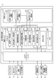
- FIG. 2 is a block diagram showing the configuration of the concentration degree determination apparatus according to an embodiment of the present invention.
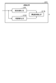
- FIG. 3 is a block diagram showing the configuration of the state detection unit according to an embodiment of the present invention.
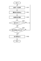
- FIG. 4 is a flowchart showing a procedure of concentration level determination by the concentration level determination apparatus shown in FIG.
- FIG. 1 is a diagram showing an overall configuration of a vehicle 1 including a concentration degree determination device 2 according to an embodiment of the present invention.
- the concentration determination device 2 is mounted on a vehicle 1 such as a passenger car.
- the configuration of the concentration determination device 2 will be described later.
- the vehicle 1 may be, for example, any one of an automobile, a bus, a truck, a train, and the like, or a vehicle on which a driver (hereinafter also referred to as a driver) other than these rides.
- the vehicle 1 includes, as basic equipment, a power unit 3 including a power source and a transmission, a steering device 4 equipped with a steering wheel 5, and further includes a manual operation mode and an automatic operation mode as operation modes. .
- An engine and / or a motor is used as the power source.
- the manual driving mode is a mode in which the vehicle 1 is driven mainly by a driver's manual driving operation, for example.
- the manual driving mode for example, an operation mode for driving the vehicle 1 based only on the driving operation of the driver and an operation for performing driving operation support control for supporting the driving operation of the driver while mainly driving the driving operation of the driver. Mode is included.
- the driving operation support control assists the steering torque so that the driver's steering becomes an appropriate steering amount based on the curvature of the curve when the vehicle 1 is traveling on the curve, for example.
- the driving operation support control includes control for assisting a driver's accelerator operation (for example, operation of an accelerator pedal) or brake operation (for example, operation of a brake pedal), manual steering (manual operation of steering), and manual speed adjustment (speed). Adjustment manual operation) is also included.
- a driver's accelerator operation for example, operation of an accelerator pedal
- brake operation for example, operation of a brake pedal
- manual steering manual operation of steering
- speed manual speed adjustment
- Adjustment manual operation is also included.
- manual steering the vehicle 1 is steered mainly by the driver's operation of the steering wheel 5.
- the speed of the vehicle 1 is adjusted mainly by the driver's accelerator operation or brake operation.
- the driving operation support control does not include control for forcibly intervening in the driving operation of the driver to automatically drive the vehicle 1. That is, in the manual driving mode, the driving operation of the driver is reflected in the driving of the vehicle 1 within a preset allowable range, but the driving of the vehicle 1 is compulsory under certain conditions (for example, lane departure of the vehicle 1). Interventive control is not included.
- the automatic operation mode is a mode for realizing an operation state in which the vehicle 1 is automatically driven along the road on which the vehicle 1 is traveling, for example.
- the automatic driving mode includes, for example, a driving state in which the vehicle 1 is automatically driven toward a preset destination without driving by the driver.
- the automatic driving mode it is not always necessary to automatically control all of the vehicle 1, and the driving state in which the driving operation of the driver is reflected in the traveling of the vehicle 1 within a preset allowable range is also included in the automatic driving mode. That is, the automatic driving mode includes control for forcibly intervening in the traveling of the vehicle 1 under certain conditions, while reflecting the driving operation of the driver in the traveling of the vehicle 1 within a preset allowable range.
- the vehicle 1 further includes an outside camera 6, a steering sensor 7, an accelerator pedal sensor 8, a brake pedal sensor 9, a GPS receiver 10, a gyro sensor 11, a vehicle speed sensor 12, a navigation device 13, an automatic An operation control device 14, a driver camera 15, an audio output device 16, and a communication device 17 are provided.
- the outside camera 6 is installed at an arbitrary position of the vehicle 1 so that the outside of the vehicle 1 can be photographed.
- the vehicle 1 may include a plurality of vehicle exterior cameras that capture different directions.
- the outside camera 6 continuously captures the driving environment in the vicinity of the vehicle 1.
- the vehicle exterior camera 6 is activated in response to the start of operation of the vehicle 1 and continuously captures the outside of the vehicle 1.
- the outside camera 6 is an example of a sensor that monitors the outside of the vehicle 1.
- the vehicle exterior camera 6 outputs the captured image (hereinafter also referred to as vehicle exterior image data) to the concentration degree determination device 2 and the automatic driving control device 14.
- the steering sensor 7 detects a steering angle.
- the steering sensor 7 outputs the detection result to the automatic driving control device 14.
- the accelerator pedal sensor 8 detects an operation amount of the accelerator pedal.
- the accelerator pedal sensor 8 outputs the detection result to the automatic operation control device 14.
- the brake pedal sensor 9 detects the operation amount of the brake pedal.
- the brake pedal sensor 9 outputs the detection result to the automatic operation control device 14.
- the GPS receiver 10 receives current position information of the vehicle 1.
- the GPS receiver 10 outputs the current position information to the concentration determination device 2, the navigation device 13, and the automatic operation control device 14.
- the gyro sensor 11 detects the behavior of the vehicle 1.
- the gyro sensor 11 outputs the detection result to the automatic operation control device 14.
- the vehicle speed sensor 12 detects the speed of the vehicle 1.
- the vehicle speed sensor 12 outputs the detection result to the automatic driving control device 14.
- the navigation device 13 is an example of a video display device that includes a display 131 that displays video.
- the navigation device 13 stores map information.
- the navigation device 13 extracts route information from the current position to the destination by using information on the destination input by the driver or the like, map information, and current position information from the GPS receiver 10.
- the navigation device 13 displays route information on the display 131.
- the navigation device 13 can also display information other than route information on the display 131.
- the navigation device 13 outputs the route information to the concentration degree determination device 2 and the automatic driving control device 14.
- the route information described above may include not only information on the route from the current position to the destination, but also information on the road environment from the current position to the destination. Some examples of information about the road environment will be described.
- the information on the road environment may include information on the type of road that passes from the current position to the destination.
- the types of roads are classified into, for example, roads in which human traffic is restricted or roads in which human traffic is not restricted.
- the road where the passage of people is restricted is, for example, an expressway.
- the highway can also be called a motorway.
- the road where the passage of people is not restricted is, for example, a general road.
- the information on the road environment may include information on the speed limit of the road that passes from the current position to the destination.
- the information regarding the road environment may include position information of an installation on the road passing from the current position to the destination.
- the installed object is, for example, a sign, but may be an object installed on the road.
- the information regarding the road environment may include position information of a building near the road passing from the current position to the destination.
- Information about the road environment may include information on the number of lanes on the road.
- the information on the road environment may include information on the position of the curve section that passes between the current position and the destination.
- Information on the road environment may include information on the curvature of the curve in the curve section.
- the information on the road environment may include information on the gradient of the road that passes between the current position and the destination. Note that the route information may include information other than the above example as information on the road environment.
- the configuration of the automatic operation control device 14 will be described.
- the automatic operation control device 14 automatically controls traveling of the vehicle 1 when the operation mode is the automatic operation mode.
- the automatic driving control device 14 includes an outside image data from the outside camera 6, a detection result from the steering sensor 7, a detection result from the accelerator pedal sensor 8, a detection result from the brake pedal sensor 9, and a GPS receiver 10. Current position information, a detection result from the gyro sensor 11, a detection result from the vehicle speed sensor 12, and route information from the navigation device 13 are acquired.
- the automatic driving control device 14 automatically controls the traveling of the vehicle 1 based on these information and traffic information acquired by road-to-vehicle communication of the communication device 17 described later.
- Automatic control includes, for example, automatic steering (automatic steering operation) and automatic speed adjustment (automatic driving of speed).
- Automatic steering is an operating state in which the steering device 4 is automatically controlled.
- Automatic steering includes LKAS (Lane Keeping Assist System).
- the LKAS automatically controls the steering device 4 so that the vehicle 1 does not deviate from the traveling lane even when the driver does not perform the steering operation.
- the steering operation of the driver may be reflected in the steering of the vehicle 1 within a range (allowable range) in which the vehicle 1 does not deviate from the travel lane even during execution of LKAS.
- automatic steering is not limited to LKAS.
- Automatic speed adjustment is an operating state in which the speed of the vehicle 1 is automatically controlled.
- Automatic speed adjustment includes ACC (Adaptive Cruise Control). For example, when there is no preceding vehicle ahead of the vehicle 1, ACC performs constant speed control that causes the vehicle 1 to travel at a constant speed at a preset speed, and when the preceding vehicle exists ahead of the vehicle 1. Is a follow-up control that adjusts the vehicle speed of the vehicle 1 in accordance with the inter-vehicle distance from the preceding vehicle.
- the automatic operation control device 14 decelerates the vehicle 1 according to the driver's brake operation (for example, operation of the brake pedal) even when ACC is being executed.
- the automatic driving control device 14 can operate the driver's accelerator operation (for example, accelerator) up to a preset maximum permissible speed (for example, the maximum speed legally determined on the traveling road) even when ACC is being executed.
- the vehicle 1 can be accelerated according to the pedal operation.
- the automatic speed adjustment is not limited to ACC but also includes CC (Cruise Control).
- the configuration of the driver camera 15 will be described.
- the driver camera 15 is installed, for example, at a position that is in front of the driver as on a dashboard.
- the driver camera 15 is an example of a sensor that monitors a driver.
- the driver camera 15 is activated in response to the start of driving of the vehicle 1 and continuously captures a predetermined range including the driver's face.
- the driver camera 15 outputs the captured image (hereinafter referred to as driver image data) to the concentration degree determination device 2.
- Driver image data is an example of monitoring data used to detect the state of the driver.
- the driver's condition is, for example, driver's forward gaze, drowsiness, looking aside, putting on and taking off clothes, telephone operation, leaning on the window / armrest, driving disturbance by passengers and pets, onset of illness, backwards, kneeling, eating and drinking , Smoking, dizziness, abnormal behavior, car navigation / audio operation, attachment / detachment of glasses / sunglasses, photography, and a degree of recognition of a subject (a degree of recognition of a subject).
- the degree of recognition is an index of how much the driver has recognized the object (for example, visually), and is the degree to which the driver is conscious by confirming the object (for example, visually).
- the state of the driver may include an index other than the index exemplified here.
- the audio output device 16 includes a speaker 161.
- the audio output device 16 outputs various information as audio.
- the communication device 17 includes a vehicle-to-vehicle communication module 171 and a road-to-vehicle communication module 172.
- the inter-vehicle communication module 171 communicates directly with another vehicle by radio.
- the inter-vehicle communication module 171 transmits, for example, information related to the vehicle 1 to another vehicle close to the vehicle 1 by inter-vehicle communication.
- the information regarding the vehicle 1 is, for example, position information and speed information, but is not limited thereto.
- the inter-vehicle communication module 171 receives, for example, information on another vehicle that is close to the vehicle 1 from the other vehicle by inter-vehicle communication.
- the information regarding another vehicle is, for example, position information and speed information, but is not limited thereto.
- the road-to-vehicle communication module 172 communicates wirelessly with roadside devices installed on the road.
- the road-to-vehicle communication module 172 transmits, for example, information on the vehicle 1 to the roadside machine through road-to-vehicle communication.
- the road-to-vehicle communication module 172 receives various information exemplified below from the roadside machine through road-to-vehicle communication.
- the road-to-vehicle communication module 172 may receive, for example, information about another vehicle that is close to the vehicle 1 from the roadside machine.
- the road-to-vehicle communication module 172 may receive traffic information from a roadside machine, for example.
- the traffic information may include, for example, lane regulation information and closed information.
- the traffic information may include, for example, signal information related to the display of signals installed in the vicinity of the roadside machine.
- the road-to-vehicle communication module 172 may receive weather information from a roadside machine, for example.
- the road-vehicle communication module 172 may receive, for example, information on the presence / absence of a person crossing a road near the roadside machine from the roadside machine.
- the road-vehicle communication module 172 may receive information other than the information described above from the roadside machine.
- the communication device 17 outputs the information obtained by the vehicle-to-vehicle communication and the road-to-vehicle communication as described above to the concentration degree determination device 2 and the automatic driving control device 14.
- the concentration level determination device 2 estimates the driver's concentration level based on the above-described driver state, and determines whether or not the driver is in a state suitable for driving the vehicle 1.
- the driving concentration degree is a degree suitable for the driver to drive the vehicle 1. As the driving concentration increases, the driver becomes more suitable for driving the vehicle 1. Conversely, as the degree of driving concentration decreases, the driver becomes more unsuitable for driving the vehicle 1.
- FIG. 2 is a block diagram illustrating a configuration of the concentration determination device 2 as an example.
- the concentration degree determination device 2 includes an input / output interface unit 21, a storage unit 22, and a control unit 23.
- the input / output interface unit 21 connects the outside camera 6, the GPS receiver 10, the navigation device 13, the automatic operation control device 14, the driver camera 15, the audio output device 16, and the communication device 17 to the control unit 23.
- the configuration of the storage unit 22 will be described.
- the storage unit 22 is a non-volatile memory that can be written and read at any time, such as a solid state drive (SSD) and a hard disk drive (HDD).
- the storage unit 22 includes a driver image data storage unit 221, a vehicle exterior image data storage unit 222, and a concentration level table storage unit 223.
- the driver image data storage unit 221 stores driver image data that the control unit 23 acquires from the driver camera 15.
- the vehicle exterior image data storage unit 222 stores vehicle exterior image data that the control unit 23 acquires from the vehicle exterior camera 6.
- the concentration level table storage unit 223 stores a concentration level table used by the control unit 23 to estimate the driving concentration level.
- the concentration degree table associates the state of the driver with a plurality of levels corresponding to the degree of driving concentration for each index.
- the plurality of levels are divided into, for example, three levels of level 1, level 2, and level 3, but the present invention is not limited to this.
- the driving concentration is set to be lower as the level number is larger, but the present invention is not limited to this. It may be set such that the driving concentration increases as the level number increases.
- Level 1 is associated with, for example, the state of a driver who is looking at a direction tilted at an angle in the range of 0 degrees or more and less than the first angle with respect to the traveling direction of the vehicle 1. That is, Level 1 is a state in which the driver is not looking aside and driving concentration is high.
- Level 2 is associated with, for example, the state of the driver who is looking at a direction tilted at an angle in the range of the first angle and less than the second angle with respect to the traveling direction of the vehicle 1.
- Level 2 is a state in which the driver is looking aside and has a lower driving concentration than Level 1.
- Level 3 is associated with, for example, the state of the driver who is looking at a direction inclined at an angle equal to or greater than the second angle with respect to the traveling direction of the vehicle 1. That is, Level 3 is a state in which the driver is looking aside and the driving concentration is lower than Level 2.
- the information managed in the concentration level table has been described by taking a side look as an example, but the same applies to other indexes.
- the configuration of the control unit 23 will be described.
- the control unit 23 includes a processor 231 and a memory 232.
- the processor 231 is, for example, a CPU (Central Processing Unit) that constitutes a computer.
- the configuration of each unit included in the processor 231 will be described later. Note that although one processor 231 is shown in FIG. 2, the control unit 23 may include one or more processors.
- the memory 232 includes a program that causes the processor 231 to function as each unit included in the processor 231.
- the program can also be referred to as an instruction for operating the processor 231.
- the program is stored in the storage unit 22 and is read from the storage unit 22 to the memory 232.
- the program in the memory 232 is read by the processor 231.
- One embodiment may be realized by a program.
- the processor 231 includes a monitoring data acquisition unit 2311, a vehicle exterior image data acquisition unit 2312, a route information acquisition unit 2313, a current position information acquisition unit 2314, a state detection unit 2315, a concentration degree estimation unit 2316, and a reference comparison unit. 2317, a traveling state detection unit 2318, and a signal output unit 2319. Each unit may be distributed among one or more processors.
- the monitoring data acquisition unit 2311 acquires driver image data from the driver camera 15 via the input / output interface unit 21.
- the monitoring data acquisition unit 2311 stores the driver image data in the driver image data storage unit 221.
- the vehicle exterior image data acquisition unit 2312 acquires vehicle exterior image data from the vehicle exterior camera 6 via the input / output interface unit 21.
- the vehicle exterior image data acquisition unit 2312 stores the vehicle exterior image data in the vehicle exterior image data storage unit 222.
- the route information acquisition unit 2313 acquires route information from the navigation device 13 via the input / output interface unit 21.
- the route information acquisition unit 2313 outputs the route information to the state detection unit 2315 and the traveling state detection unit 2318.
- the current position information acquisition unit 2314 acquires current position information from the GPS receiver 10 via the input / output interface unit 21.
- the current position information acquisition unit 2314 outputs the current position information to the state detection unit 2315 and the traveling state detection unit 2318.
- the state detection unit 2315 detects the state of the driver from the driver image data stored in the driver image data storage unit 221. In addition to the driver image data, the state detection unit 2315 detects, for example, the above-described object recognition degree as the driver's state using at least one of image data outside the vehicle, route information, and current position information. Also good. An example of detection of the driver's state by the state detection unit 2315 will be described later. Note that the state detection unit 2315 may acquire the driver image data from the monitoring data acquisition unit 2311 without using the driver image data storage unit 221. In this case, the storage unit 22 may not include the driver image data storage unit 221. The state detection unit 2315 outputs the driver's state to the concentration degree estimation unit 2316.
- the concentration level estimation unit 2316 estimates the driver's driving concentration level based on the driver's state detected by the state detection unit 2315. Note that since the driver's state is detected from the driver image data as described above, the concentration degree estimation unit 2316 can estimate the driver's driving concentration degree from the driver image data.
- the concentration degree estimation unit 2316 estimates a driving concentration degree corresponding to each of one or more indexes included in the driver's state.
- the concentration level estimation unit 2316 estimates, for example, the driving concentration level using sleepiness as an index, and also estimates the driving concentration level using a side look as an index. Note that the concentration degree estimation unit 2316 may estimate a single driving concentration degree based on, for example, a plurality of indexes included in the driver's state. In this case, the concentration degree estimation unit 2316 may estimate a single driving concentration degree by appropriately weighting each index. The weight set for each index may be arbitrarily changed.
- the concentration degree estimation unit 2316 can estimate the driving concentration degree by a numerical value such as a ratio.
- the numerical value estimated by the concentration degree estimation unit 2316 may increase as the driving concentration degree increases, or may decrease as the driving concentration degree increases.
- the concentration degree estimation unit 2316 refers to the concentration degree table stored in the concentration degree table storage unit 223 and estimates the level of driving concentration corresponding to the driver's state from a plurality of levels. be able to. Note that when the concentration level estimation unit 2316 estimates the driving concentration level numerically, the storage unit 22 may not include the concentration level table storage unit 223.
- the estimation of the driving concentration by the concentration estimating unit 2316 may be performed using an AI (Artificial Intelligence) function such as machine learning or deep learning.
- AI Artificial Intelligence
- the concentration degree estimation unit 2316 can estimate the state of the driver with high accuracy by using the past estimation result for estimation of the current driving concentration degree, for example.
- the reference comparison unit 2317 compares the driving concentration level estimated by the concentration level estimation unit 2316 with the reference.
- the reference comparison unit 2317 may compare the driving concentration level for each of the plurality of indexes with the reference.
- the concentration level estimation unit 2316 estimates a single driving concentration level based on a plurality of indices
- the reference comparison unit 2317 may compare the single driving concentration level with a reference.
- the reference comparison unit 2317 compares, for example, the driving concentration degree estimated by the concentration degree estimation unit 2316 with a reference value or reference level serving as a reference.
- the reference comparison unit 2317 determines that the driving concentration degree satisfies the reference.
- the reference comparison unit 2317 outputs the comparison result to the signal output unit 2319. Note that the reference may be arbitrarily changed.
- the comparison between the driving concentration degree estimated by the numerical value by the reference comparison unit 2317 and the reference will be described.
- the reference value is a numerical value A. If the numerical value estimated by the concentration degree estimation unit 2316 is smaller than the numerical value A, which is the reference value, the reference comparison unit 2317 determines that the driving concentration degree estimated by the concentration degree estimation unit 2316 is lower than the reference value.
- the reference comparison unit 2317 determines that the driving concentration degree estimated by the concentration degree estimation unit 2316 is lower than the reference value.
- the reference level is level B extracted from a plurality of levels.
- the reference comparing unit 2317 indicates that the driving concentration degree estimated by the concentration degree estimating unit 2316 is the reference level. Judged to be lower than the level.
- the concentration level table associates the state of the driver with the three levels of Level 1, Level 2, and Level 3 for each index.
- the reference level is level 1.
- the reference comparison unit 2317 determines that level 2 or level 3 estimated by the concentration degree estimation unit 2316 is lower than level 1, which is the reference level.
- the reference comparison unit 2317 determines that the level 1 estimated by the concentration degree estimation unit 2316 is not lower than the level 1 that is the reference level.
- the driving state detection unit 2318 detects a position where the driving state of the vehicle 1 changes (hereinafter also referred to as a driving state change position) when the driving mode of the vehicle 1 is the automatic driving mode.
- a driving state change position a position where the driving state of the vehicle 1 changes
- the change in the running state is, for example, the behavior of the vehicle 1 in which at least one of the acceleration in the traveling direction of the vehicle 1 and the acceleration in the direction orthogonal to the traveling direction changes by a predetermined amount or more or a predetermined ratio.
- the predetermined amount or the predetermined ratio may be arbitrarily changed.
- the change in the running state may be evaluated by data other than acceleration.
- the change in the running state may cause, for example, a change in vehicle behavior (yawing, rolling, pitching). The driver is surprised when the vehicle behavior changes more than a certain level in a state where the driving concentration is low.
- the change in the running state of the vehicle 1 is not particularly limited, and is, for example, acceleration, deceleration, stop, lane change, entry into a curve section, right turn or left turn of the vehicle 1.
- the right turn or left turn may include a U-turn.
- the change in the running state of the vehicle 1 may be switching between forward and reverse.
- the change in the running state of the vehicle 1 may be a change in the uneven state of the road surface.
- the change in the uneven state of the road surface is, for example, an uneven road, a rough road, an unpaved road, an approach to a road under construction, or the like.
- the traveling state detection unit 2318 further monitors that the vehicle 1 reaches a position X before the traveling state change position.
- the traveling state detection unit 2318 detects that the vehicle 1 has reached the position X
- the traveling state detection unit 2318 outputs a detection result indicating that the vehicle 1 has reached the position X to the signal output unit 2319.
- the position X is a position where the signal output unit 2319 outputs an instruction signal instructing the driver to execute a predetermined notification output, as will be described later. Therefore, the position X is not particularly limited as long as it is between the current position of the vehicle 1 and the traveling state change position, but is preferably near the traveling state change position.
- the position X may be a position where the distance to the traveling state change position is a predetermined distance, for example.
- the predetermined distance may be arbitrarily changed.
- the traveling state detection unit 2318 may monitor that the vehicle 1 reaches the position X as in the following example.
- the traveling state detection unit 2318 sets a position X that is a predetermined distance returned from the traveling state change position to the current position side of the vehicle 1 as a position X.
- the traveling state detection unit 2318 compares the current position of the vehicle 1 with the position X, and monitors that the vehicle 1 reaches the position X.
- the position X may be, for example, a position where the vehicle 1 is estimated to reach the traveling state change position after a predetermined time.
- the predetermined time may be arbitrarily changed.
- the traveling state detection unit 2318 may monitor that the vehicle 1 reaches the position X as in the following example.
- the traveling state detection unit 2318 refers to the speed of the vehicle 1 and sets, as the position X, a position where the vehicle 1 is estimated to reach the traveling state change position after a predetermined time.
- the traveling state detection unit 2318 compares the current position of the vehicle 1 with the position X, and monitors that the vehicle 1 reaches the position X.
- the travel state detection unit 2318 refers to the speed of the vehicle 1 and estimates the time when the vehicle 1 reaches the travel state change position (hereinafter also referred to as change position arrival time).
- the traveling state detection unit 2318 sets the time when the vehicle 1 passes the position X as the time returned from the change position arrival time by a predetermined time.
- the traveling state detection unit 2318 compares the time when the vehicle 1 passes the position X with the current time, and monitors that the vehicle 1 reaches the position X.
- the configuration of the signal output unit 2319 will be described.
- the signal output unit 2319 outputs a signal to each unit via the input / output interface unit 21.
- examples of some signals output from the signal output unit 2319 will be described.
- the signal output unit 2319 When the driving mode is the automatic driving mode and the driving concentration does not satisfy the standard, the signal output unit 2319 outputs the above instruction signal before the vehicle 1 reaches the traveling state change position.
- the signal output unit 2319 can recognize that the operation mode is the automatic operation mode, for example, as follows.
- the concentration degree determination device 2 may receive a signal from the automatic operation control device 14 when the operation mode is switched from the manual operation mode to the automatic operation mode.
- the signal output unit 2319 can recognize that the operation mode is the automatic operation mode based on the signal from the automatic operation control device 14.
- the signal output unit 2319 can recognize based on the comparison result from the reference comparison unit 2317 that the driving concentration does not satisfy the standard.
- the signal output unit 2319 can recognize that the vehicle 1 has reached the position X before the travel state change position based on the detection result from the travel state detection unit 2318.
- the signal output unit 2319 outputs an instruction signal instructing the driver to execute a predetermined notification output based on reception of the detection result from the traveling state detection unit 2318. Thereby, the signal output unit 2319 can output an instruction signal before the vehicle 1 reaches the traveling state change position.
- the notification providing apparatus receives the instruction signal from the signal output unit 2319, the notification providing apparatus outputs a predetermined notification to the driver.
- the notification providing device is, for example, the navigation device 13 and the audio output device 16.
- the navigation device 13 displays, on the display 131, an image or video notification that informs the driver of changes in the driving state based on the instruction signal, for example.
- the audio output device 16 outputs, for example, a notification that informs the driver of changes in the running state from the speaker 161.
- the notification is not limited as long as it is a content that informs the driver of changes in the driving state or changes in the vehicle behavior or prompts a response to such changes.
- the driver can recognize from the notification that the vehicle 1 is approaching the travel state change position, and can prepare for a change in the travel state or a change in the vehicle behavior.
- the signal output unit 2319 may output the instruction signal to a device other than the navigation device 13 and the voice output device 16.
- the signal output unit 2319 may output an instruction signal to a notification providing apparatus that gives an external stimulus such as vibration to the driver as a notification.
- the signal output unit 2319 can output an instruction signal when one or more driving concentration degrees out of a plurality of driving concentration degrees estimated from a plurality of indices do not satisfy the standard.
- the signal output unit 2319 may output an instruction signal when a predetermined number or more of the driving concentration degrees estimated from the plurality of indexes do not satisfy the standard.
- the signal output unit 2319 may output an instruction signal when a single degree of driving concentration estimated based on a plurality of indices does not satisfy the standard.
- the signal output unit 2319 may output a switching signal for switching the operation mode to the automatic operation control device 14.
- FIG. 3 is a block diagram illustrating a configuration of the state detection unit 2315.
- the state detection unit 2315 includes a local state detection unit 23151, a global state detection unit 23152, and a driver state detection unit 23153.
- the local state detection unit 23151 detects the state of at least one of the organs included in the driver's face in the driver image data.
- the organs included in the face are, for example, the eyes, mouth, nose and ears, but other organs may be used.
- the local state detection unit 23151 detects an eye state
- the local state detection unit 23151 detects, for example, a driver's eye open / closed degree, a line-of-sight direction, a face direction, and the like.
- Local state detection unit 23151 outputs a detection result (hereinafter also referred to as local information) to driver state detection unit 23153.
- the global state detection unit 23152 detects at least one of the global states of the driver in the driver image data.
- the global state is, for example, the movement and posture of the driver, but may be other than these.
- the global state detection unit 23152 outputs a detection result (hereinafter also referred to as global information) to the driver state detection unit 23153.
- the driver state detection unit 23153 detects the above-described driver state using the local information from the local state detection unit 23151 and the global information from the global state detection unit 23152.
- the state detection unit 2315 can detect various driver states by combining local information and global information, for example.
- the state detection unit 2315 can detect the degree of object recognition using the monitoring data and the position information of the object.
- the state detection unit 2315 can detect the degree of object recognition by the driver's vision using the image data outside the vehicle in addition to the driver image data as follows.
- the state detection unit 2315 extracts a target for detecting the degree of object recognition from the image data outside the vehicle.
- the target is, for example, an installation such as a sign or a building, but is not particularly limited as long as the driver may confirm (for example, visually) and be aware of it.
- the state detection unit 2315 detects the driver's line of sight and face orientation from the driver image data captured at substantially the same timing as when the image data outside the vehicle from which the target was extracted was captured.
- the driver's line of sight and face orientation are detected by the local state detection unit 23151 as described above.
- the state detection unit 2315 detects the degree of object recognition using at least one of the driver's line of sight and face orientation and the position information of the object. It can be said that the degree of object recognition increases as the driver's line of sight and face direction face the object.
- the state detection unit 2315 has a high degree of object recognition on condition that at least one of the driver's line of sight and face orientation is in a state that matches the position of the object for a predetermined time. It may be detected. On the other hand, when at least one of the driver's line of sight and face orientation is directed to the target position but passes without recognizing the target, the state detection unit 2315 detects that the degree of target recognition is low. May be. The state detection unit 2315 may detect the degree of object recognition in accordance with the length of time that the driver stays in a state where at least one of the driver's line of sight and face orientation matches the target position.
- the state detection unit 2315 may estimate the degree of object recognition based on the presence or absence of a specific driving operation or a driver's action that is assumed to result from the driver's recognition of the object. For example, when the driver recognizes that a pedestrian is present near the pedestrian crossing in front of the vehicle 1, it is assumed that the driver performs a deceleration operation. Therefore, when the concentration determination device 2 detects that a pedestrian is present near the pedestrian crossing in front of the vehicle 1, the state detection unit 2315 detects the driver's deceleration operation, and the degree of object recognition is You may detect that it is high.
- the state detection unit 2315 detects the driver's deceleration operation even after a predetermined time has elapsed. If not, it may be detected that the degree of object recognition is low. For example, depending on the length of time from when the concentration determination device 2 detects a target pedestrian until the driver's deceleration operation is detected, the state detection unit 2315 may detect the target recognition degree. Good.
- the state detection unit 2315 can detect the degree of object recognition using route information and current position information in addition to driver image data as follows.
- the state detection unit 2315 refers to the route information and the current position information and extracts a target located in the vicinity of the vehicle 1.
- the target is, for example, an installation such as a sign or a building, but is not particularly limited as long as the driver may confirm (for example, visually) and recognize it.
- the state detection unit 2315 detects the driver's line of sight and the direction of the face from the driver image data captured at substantially the same timing as when the vehicle 1 passes through the vicinity of the target.
- the state detection unit 2315 detects the degree of object recognition using at least one of the driver's line of sight and face orientation and the position information of the object.
- the state detection unit 2315 may obtain the target position and the timing at which the vehicle 1 passes near the target through road-to-vehicle communication. In this case, the state detection unit 2315 detects the driver's line of sight and face direction from the driver image data captured at substantially the same timing as the vehicle 1 passes through the vicinity of the target. The state detection unit 2315 detects the degree of object recognition using at least one of the driver's line of sight and face orientation and the position information of the object.
- the state detection unit 2315 may use an image or video displayed on the display 131 of the navigation device 13 as a target. In this case, the state detection unit 2315 detects the driver's line of sight and face direction from the driver image data captured at substantially the same timing as when the image or video is displayed on the display 131. The state detection unit 2315 detects the degree of object recognition using at least one of the driver's line of sight and face orientation and the position information of the object.
- the state detection unit 2315 can appropriately detect the driver's state using the degree of object recognition as an index.
- the state detection unit 2315 may use an object located in the vicinity of the front, rear, left, or right of the vehicle 1.
- the state detection unit 2315 preferably uses an object located near the left side or the right side rather than the front side of the vehicle 1. If the object is located on the front side of the vehicle 1, the driver's line of sight and face do not move much. On the other hand, if the object is located near the left side or right side of the vehicle 1, the driver's line of sight and face move to the left or right side. Therefore, the state detection unit 2315 can appropriately detect the target recognition degree.
- the traveling state detection unit 2318 may detect the traveling state change position by a method other than the detection example shown here. As an example, the traveling state detection unit 2318 may use the route information of the vehicle 1 acquired from the navigation device 13 via the route information acquisition unit 2313. The travel state detection unit 2318 can detect a travel state change position on a route on which the vehicle 1 is to travel based on various information included in the route information of the vehicle 1. Hereinafter, several detection examples of the traveling state change position based on the route information of the vehicle 1 will be described.
- the traveling state detection unit 2318 may detect the traveling state change position based on, for example, speed limit information included in the route information. For example, the traveling state detection unit 2318 may detect or estimate the vicinity of a position where sections having different speed limits are adjacent as a position where acceleration or deceleration of the vehicle 1 occurs. If the difference between the speed limits of adjacent sections is equal to or less than a predetermined value, the traveling state detection unit 2318 may not detect the vicinity of the position where the sections with different speed limits are adjacent as the traveling state change position. The reason is that even if the speed limit changes, the change in the running state of the vehicle 1 is small.
- the traveling state detection unit 2318 may detect a traveling state change position based on, for example, gradient information included in the route information. For example, the traveling state detection unit 2318 may detect or estimate the vicinity of a position where sections with different gradients are adjacent as a position where acceleration or deceleration of the vehicle 1 occurs. If the difference in gradient between adjacent sections is equal to or less than a predetermined value, the traveling state detection unit 2318 may not detect the vicinity of a position where adjacent sections with different gradients are adjacent as the traveling state change position. The reason is that even if the gradient changes, the change in the running state of the vehicle 1 is small.
- the traveling state detection unit 2318 may detect the traveling state change position based on, for example, information on a route included in the route information. For example, the traveling state detection unit 2318 may detect or estimate the destination as a position where the stop of the vehicle 1 occurs.
- the traveling state detection unit 2318 may detect the traveling state change position based on, for example, information on a route included in the route information. For example, the traveling state detection unit 2318 may detect or estimate the position near the interchange where the vehicle 1 gets off the highway as the position where the lane change of the vehicle 1 occurs.
- the traveling state detection unit 2318 may detect the traveling state change position based on, for example, information on the position of the curve section included in the route information. For example, the traveling state detection unit 2318 may detect or estimate the start position of the curve section as a position where the vehicle 1 enters the curve section. If the curvature of the curve section is equal to or less than the predetermined value, the traveling state detection unit 2318 may not detect the curve section as the traveling state change position. The reason is that even if the vehicle 1 enters a curve section with a small curvature, the change in the running state of the vehicle 1 is small.
- the traveling state detection unit 2318 may detect the traveling state change position based on, for example, information on a route included in the route information. For example, the traveling state detection unit 2318 may detect or estimate a position where the traveling direction of the vehicle 1 changes by a predetermined angle or more as a position where the vehicle 1 turns right or left.
- the traveling state detection unit 2318 may detect the traveling state change position based on, for example, information on the road surface state of the road included in the road environment information.
- the information regarding the road surface condition of the road is, for example, information about an unpaved section and a section under road surface construction.
- the traveling state detection unit 2318 can detect the uneven state of the road surface based on, for example, information on the road surface state of the road.
- the traveling state detection unit 2318 may detect or estimate a position where a change in the uneven state of the road surface occurs based on detection of the uneven state of the road surface.
- the traveling state detection unit 2318 may detect the traveling state change position based on position information such as a parking lot included in the route information, for example. For example, the traveling state detection unit 2318 may detect or estimate a position such as a parking lot as a position where the vehicle 1 is switched between forward and reverse. Note that the traveling state detection unit 2318 may detect the forward / backward switching of the vehicle 1 that is the content of the change in the traveling state based on the vehicle control information by the parking device or the like.
- the traveling state detection unit 2318 may use information obtained from the communication device 17.
- the traveling state detection unit 2318 can detect the traveling state change position based on information obtained from at least one of inter-vehicle communication and road-to-vehicle communication.
- the traveling state detection unit 2318 detects the position of the vehicle that interferes with the traveling of the vehicle 1 based on, for example, information on another vehicle obtained by inter-vehicle communication or road-to-vehicle communication.
- the traveling state detection unit 2318 can detect the vicinity of the position of the vehicle that interferes with traveling of the vehicle 1 as the traveling state change position.
- the traveling state detection unit 2318 detects the position of a person who interferes with the traveling of the vehicle 1 based on, for example, information on the presence or absence of a person who crosses a road in the vicinity of a roadside machine obtained by road-to-vehicle communication.
- the traveling state detection unit 2318 can detect the vicinity of the position of a person who interferes with traveling of the vehicle 1 as the traveling state change position.
- the traveling state detection unit 2318 detects a lane-restricted position or a closed position based on traffic information obtained by road-to-vehicle communication, for example.
- the travel state detection unit 2318 can detect a lane-restricted position or a closed position as the travel state change position.
- the traveling state detection unit 2318 may detect or estimate how the traveling state changes at the traveling state change position with reference to various information.
- the traveling state detection unit 2318 may use, for example, information on the road environment included in the distance and route information from the current position of the vehicle 1 to the traveling state change position.
- the road environment information is, for example, the number of lanes on the road on which the vehicle 1 is traveling, but is not limited thereto.
- the traveling state detection unit 2318 detects or estimates acceleration, deceleration, stop, lane change, entry into a curve section, right turn or left turn at the traveling state change position.
- the traveling state detection unit 2318 may use data acquired from a sensor that monitors the outside of the vehicle 1.
- the traveling state detector 2318 can detect the traveling state change position based on data taken from a sensor that monitors the outside of the vehicle 1.
- the case where the sensor for monitoring the outside of the vehicle 1 is the outside camera 6 will be described as an example.
- the sensor that monitors the outside of the vehicle 1 is not limited to the outside camera 6.
- the sensor that monitors the outside of the vehicle 1 may be, for example, a radar that detects an object located in the vicinity of the vehicle 1 by radio waves.
- the traveling state detection unit 2318 detects an object (hereinafter simply referred to as an object) that hinders the traveling of the vehicle 1 and a distance from the vehicle 1 to the object from the image data outside the vehicle.
- the object include, but are not limited to, a vehicle stopped due to a failure or an accident, a fallen object, and the like.
- the traveling state detection unit 2318 can detect the vicinity of the position of the object as the traveling state change position.
- the traveling state detection unit 2318 may detect a person who interferes with the traveling of the vehicle 1 from the image data outside the vehicle.
- the person who interferes with the traveling of the vehicle 1 is, for example, a person who crosses the front of the vehicle 1.
- the traveling state detection unit 2318 may detect or estimate how the traveling state changes at the traveling state change position with reference to various information.
- the traveling state detection unit 2318 may use, for example, information on the road environment included in the distance and route information from the current position of the vehicle 1 to the traveling state change position.
- the road environment information is, for example, the number of lanes on the road on which the vehicle 1 is traveling, but is not limited thereto.
- the traveling state detection unit 2318 detects or estimates acceleration, deceleration, stop, lane change, entry into a curve section, right turn or left turn at the traveling state change position.
- the traveling state detection unit 2318 may detect the traveling state change position by combining two or more of route information, information obtained from the communication device 17, and image data outside the vehicle, for example.
- the traveling state detection unit 2318 may detect the traveling state change position based on route information and weather information included in traffic information obtained from the communication device 17.
- the traveling state detection unit 2318 may detect more traveling state change positions than when the weather is clear.
- FIG. 4 is a flowchart showing a procedure as an example of concentration level determination by the concentration level determination device 2 when the operation mode is the automatic operation mode.
- the monitoring data acquisition unit 2311 acquires monitoring data from a sensor that monitors the driver of the vehicle 1 (step S101). In step S ⁇ b> 101, the monitoring data acquisition unit 2311 acquires driver image data from the driver camera 15 via, for example, the input / output interface unit 21. Note that the interval at which the monitoring data acquisition unit 2311 acquires the monitoring data may be the same as or shorter than the interval at which the state detection unit 2315 detects the driver's state.
- the state detection unit 2315 detects the driver's state from the monitoring data (step S102).
- the state detection unit 2315 detects the state of the driver from the driver image data, for example.
- the state detection unit 2315 can detect the state of the driver at a predetermined interval, for example.
- the state detection unit 2315 may detect the state of the driver at an arbitrary timing.
- the concentration degree estimation unit 2316 estimates the driver's driving concentration degree from the monitoring data (step S103).
- the concentration degree estimation unit 2316 estimates the driving concentration degree based on the state of the driver detected from the driver image data by the state detection unit 2315, for example.
- the reference comparison unit 2317 compares the driving concentration with the reference (step S104).
- the processing of the concentration degree determination device 2 may transition from step S104 to step S101.
- the traveling state detection unit 2318 determines whether the vehicle 1 is close to the traveling state change position (Step S105). In step S105, for example, when the traveling state detection unit 2318 determines that the vehicle 1 has reached the position X, it determines that the vehicle 1 is close to the traveling state change position. For example, when it is determined that the vehicle 1 has not reached the position X, the traveling state detection unit 2318 determines that the vehicle 1 is not close to the traveling state change position.
- Step S105 the processing of the concentration degree determination device 2 may transition from Step S105 to Step S101.
- step S105 Yes
- the signal output unit 2319 outputs an instruction signal (step S106). That is, in step S106, when the driving mode is the automatic driving mode and the driving concentration does not satisfy the standard, the signal output unit 2319 outputs an instruction signal before the vehicle 1 reaches the traveling state change position. To do.
- the concentration degree estimation part 2316 may be made to estimate a driving concentration degree using a driver
- the concentration degree estimation unit 2316 may estimate the driving concentration degree using only the driver's eating and drinking as an index.
- the concentration degree estimation unit 2316 may estimate a single driving concentration degree based on a combination of the driver's eating and drinking and one or more other indicators. For example, when the driver is eating and drinking, the concentration degree estimation unit 2316 estimates that the driving concentration degree is lower than that when the driver is not eating and drinking.
- the concentration determination device 2 determines that the vehicle 1 is in the driving state change position.
- An instruction signal can be output before reaching.
- the driver can recognize that the vehicle 1 is approaching the traveling state change position by the notification based on the instruction signal. Therefore, before the vehicle 1 reaches the travel state change position, the driver can prepare for the behavior of the vehicle 1 at the travel state change position, such as stopping eating and drinking. Even if the vehicle 1 passes the travel state change position, the driver does not spill food or drink. Therefore, the driver can ride on the vehicle 1 comfortably.
- the traveling state detection unit 2318 may detect the traveling state change position using the route information as described above. According to this example, the traveling state detection unit 2318 can detect the traveling state change position on the route on which the vehicle 1 is traveling with high accuracy. Furthermore, the traveling state detection unit 2318 can detect with high accuracy how the traveling state changes at the traveling state change position.
- the traveling state detection unit 2318 may detect the traveling state change position using the information acquired from the communication device 17 as described above. According to this example, the traveling state detection unit 2318 can detect a traveling state change position based on a sudden event that occurs in the vicinity of the vehicle 1 or on a route on which the vehicle 1 is scheduled to travel. Therefore, the traveling state detection unit 2318 can detect a traveling state change position that cannot be detected from the route information.
- the traveling state detection unit 2318 may detect the traveling state change position using data acquired from a sensor that monitors the outside of the vehicle 1 as described above. According to this example, the traveling state detection unit 2318 can detect a traveling state change position based on a sudden event that occurs in the vicinity of the vehicle 1. Therefore, the traveling state detection unit 2318 can detect a traveling state change position that cannot be detected from the route information.
- the change in the travel state detected or estimated by the travel state detection unit 2318 in step S105 is not particularly limited.
- the vehicle 1 may be accelerated, decelerated, stopped, changed lanes, entered into a curve section, turned right or left. There may be.
- the concentration degree determination device 2 can detect a change in the driving state that easily affects the driver's posture. Even if the vehicle passes through the travel state change position, the driver is not surprised or distracted by the change in the travel state of the vehicle.
- the signal output unit 2319 may include the content of the change in the running state detected or estimated by the running state detection unit 2318 in the instruction signal.
- the driver can recognize not only that the vehicle 1 is approaching the travel state change position but also how the travel state changes at the travel state change position.
- the driver can take a posture corresponding to a change in the running state.
- the concentration degree determination device 2 determines that the vehicle 1 is in the running state change position when the operation mode is the automatic operation mode and the operation concentration degree does not satisfy the standard.
- An instruction signal can be output before reaching.
- the driver can recognize that the vehicle 1 is approaching the traveling state change position by the notification based on the instruction signal. Therefore, before the vehicle 1 reaches the traveling state change position, the driver can prepare for the behavior of the vehicle 1 at the traveling state change position. Even if the vehicle 1 passes through the travel state change position, the driver will not be surprised or distracted by the change in the travel state of the vehicle 1.
- the concentration determination device 2 does not output an instruction signal. If the driving concentration satisfies the standard, it can be said that the driver pays attention to the environment outside the vehicle 1. If the vehicle 1 approaches the running state change position, the driver can easily recognize the running state change position. Therefore, the driver can prepare for the behavior of the vehicle 1 at the traveling state change position without receiving notification.
- the concentration degree determination device 2 can consider driving comfort in the automatic driving mode.
- the concentration determination device 2 detects the driver's state by using the driver image data captured by the driver camera 15 as monitoring data, and estimates the driving concentration.
- the monitoring data is not limited to the driver image data.
- the monitoring data may be, for example, biological data obtained by a biological sensor that monitors the driver of the vehicle 1.
- the biological sensor is, for example, a pulse wave sensor or a heart rate sensor.
- the biological sensor is not limited to these as long as it can monitor the driver.
- the biological sensor may be a contact sensor or a non-contact sensor.
- the concentration degree determination device 2 can detect the state of the driver from the biological data.
- the state of the driver detected from the biological data is an index such as a pulse wave or a heartbeat.
- the monitoring data may be, for example, data obtained by a sensor that measures the strength of the driver's steering wheel 5 installed on the steering wheel 5.
- the present invention is not limited to the above-described embodiment as it is, and can be embodied by modifying the constituent elements without departing from the scope of the invention in the implementation stage.
- various inventions can be formed by appropriately combining a plurality of constituent elements disclosed in the embodiment. For example, some components may be deleted from all the components shown in the embodiment. Furthermore, you may combine the component covering different embodiment suitably.
- the above embodiment may be realized by a storage medium such as a ROM (Read Only Memory) that stores a program that causes the processor 231 to function as each unit included in the processor 231.
- a storage medium such as a ROM (Read Only Memory) that stores a program that causes the processor 231 to function as each unit included in the processor 231.
- a processor configured to output an instruction signal indicating the output of A memory for storing instructions for operating the processor;
Landscapes
- Physics & Mathematics (AREA)
- General Physics & Mathematics (AREA)
- Engineering & Computer Science (AREA)
- Automation & Control Theory (AREA)
- Mathematical Physics (AREA)
- Transportation (AREA)
- Mechanical Engineering (AREA)
- Traffic Control Systems (AREA)
Abstract
運転の快適性に配慮するようにする。 集中度判定装置は、車両の運転者を監視するセンサから監視データを取得する監視データ取得部と、前記監視データから前記運転者の運転集中度を推定する集中度推定部と、前記運転集中度を基準と比較する基準比較部と、前記車両の運転モードが自動運転モードである場合に、前記車両の走行状態が変化する位置を検出する走行状態検出部と、前記運転モードが自動運転モードであり、かつ、前記運転集中度が前記基準を満たさない場合、前記走行状態が変化する位置に前記車両が到達する前に、前記運転者に対して所定の通知の出力を指示する指示信号を出力する信号出力部とを備える。
Description
この発明は、例えば、車両の運転者の集中度を判定する集中度判定装置、集中度判定方法及び集中度判定のためのプログラムに関する。
近年、車両の運転モードとして、運転者の運転操作に基づいて車両を走行させる手動運転モード以外に、運転者の運転操作によらず予め設定された経路に沿って車両を走行させる自動運転モードの開発が進められている。
運転中における運転者の注意行動を検出して、運転者に警告する技術の開発も進められている(特開2014-181020号公報参照)。
車両の運転モードが自動運転モードであっても、運転者には運転の安全性が求められている。そのため、運転者は、基準を満たす運転集中度を保つ必要がある。運転者の運転集中度が低下している場合に車両が通知を出せば、運転の安全性は保たれる。しかしながら、車両が運転者にとって必要なタイミングで通知を出さなければ、運転者の運転の快適性は損なわれる。
この発明は、上記事情に着目してなされたもので、自動運転モードにおける運転の快適性に配慮することができる集中度判定装置、集中度判定方法及び集中度判定のためのプログラムを提供しようとするものである。
上記課題を解決するために、この発明の第1の態様は、車両の運転者を監視するセンサから監視データを取得する監視データ取得部と、前記監視データから前記運転者の運転集中度を推定する集中度推定部と、前記運転集中度を基準と比較する基準比較部と、前記車両の運転モードが自動運転モードである場合に、前記車両の走行状態が変化する位置を検出する走行状態検出部と、前記運転モードが自動運転モードであり、かつ、前記運転集中度が前記基準を満たさない場合、前記走行状態が変化する位置に前記車両が到達する前に、前記運転者に対して所定の通知の出力を指示する指示信号を出力する信号出力部とを備える集中度判定装置である。
この発明の第2の態様は、第1の態様の集中度判定装置において、前記集中度推定部が、前記運転者の飲食を指標として前記運転集中度を推定するようにしたものである。
この発明の第3の態様は、第1の態様の集中度判定装置において、前記走行状態検出部が、前記車両の経路情報に基づいて、前記走行状態が変化する位置を検出するようにしたものである。
この発明の第4の態様は、第1の態様の集中度判定装置において、前記走行状態検出部が、車車間通信及び路車間通信のうちの少なくとも何れか一方で得られる情報に基づいて、前記走行状態が変化する位置を検出するようにしたものである。
この発明の第5の態様は、第1の態様の集中度判定装置において、前記走行状態検出部が、前記車両の外部を監視するセンサから取得されるデータに基づいて、前記走行状態が変化する位置を検出するようにしたものである。
この発明の第6の態様は、車両の運転者を監視するセンサから監視データを取得する監視データ取得過程と、前記監視データから前記運転者の運転集中度を推定する集中度推定過程と、前記運転集中度を基準と比較する基準比較過程と、前記車両の運転モードが自動運転モードである場合に、前記車両の走行状態が変化する位置を検出する走行状態検出過程と、前記運転モードが自動運転モードであり、かつ、前記運転集中度が前記基準を満たさない場合、前記走行状態が変化する位置に前記車両が到達する前に、前記運転者に対して所定の通知の出力を指示する指示信号を出力する信号出力過程とを備える集中度判定方法である。
この発明の第7の態様は、第1の態様から第5の態様の何れかの態様の集中度判定装置が備える各部としてコンピュータを機能させる集中度判定のためのプログラムである。
この発明の第1の態様によれば、集中度判定装置は、運転モードが自動運転モードであり、かつ、運転集中度が基準を満たさない場合、車両が走行状態変化位置に到達する前に、指示信号を出力することができる。運転者は、指示信号に基づく通知により、車両が走行状態変化位置に近づいていることを認識することができる。そのため、車両が走行状態変化位置に到達する前に、運転者は、走行状態変化位置における車両の挙動に備えることができる。車両が走行状態変化位置を通過したとしても、運転者は、車両の走行状態の変化によって驚いたり、体勢を崩したりすることはない。このように、運転者は、必要なタイミングで通知を受けることができるので、快適に車両に乗ることができる。
すなわち、第1の態様によれば、集中度判定装置は、自動運転モードにおける運転の快適性に配慮することができる。
すなわち、第1の態様によれば、集中度判定装置は、自動運転モードにおける運転の快適性に配慮することができる。
この発明の第2の態様によれば、集中度判定装置は、運転モードが自動運転モードであり、かつ、運転者の飲食を指標とする運転集中度が基準を満たさない場合に、車両が走行状態変化位置に到達する前に、指示信号を出力することができる。運転者は、指示信号に基づく通知により、車両が走行状態変化位置に近づいていることを認識することができる。そのため、車両が走行状態変化位置に到達する前に、運転者は、飲食を中止するなど、走行状態変化位置における車両の挙動に備えることができる。車両が走行状態変化位置を通過したとしても、運転者は、飲食物をこぼすことはない。そのため、運転者は、快適に車両に乗ることができる。
この発明の第3の態様によれば、集中度判定装置は、車両が走行する予定の経路における走行状態変化位置を高精度で検出することができる。さらに、集中度判定装置は、走行状態変化位置において走行状態がどのように変化するのかを高精度で検出することができる。
この発明の第4の態様によれば、集中度判定装置は、車両の近傍または車両が走行する予定の経路で発生する突発的な事象に基づく走行状態変化位置を検出することができる。
この発明の第5の態様によれば、集中度判定装置は、車両の近傍で発生する突発的な事象に基づく走行状態変化位置を検出することができる。
この発明の第6の態様によれば、集中度判定方法は、上述の第1の態様と同様の効果を得ることができる。すなわち、集中度判定方法は、自動運転モードにおける運転の快適性に配慮することができる。
この発明の第7の態様によれば、集中度判定のためのプログラムは、上述の第1の態様と同様の効果を得ることができる。すなわち、集中度判定のためのプログラムは、自動運転モードにおける運転の快適性に配慮することができる。
以下、図面を参照してこの発明に係る実施形態について説明する。
[一実施形態]
(構成)
図1は、この発明の一実施形態に係る集中度判定装置2を備えた車両1の全体構成を示す図である。集中度判定装置2は、乗用車等の車両1に搭載される。集中度判定装置2の構成については後述する。車両1は、例えば、自動車、バス、トラック及び電車等のうちの何れかであっても、これら以外の運転者(以下、ドライバとも称する)が乗る乗り物であってもよい。
[一実施形態]
(構成)
図1は、この発明の一実施形態に係る集中度判定装置2を備えた車両1の全体構成を示す図である。集中度判定装置2は、乗用車等の車両1に搭載される。集中度判定装置2の構成については後述する。車両1は、例えば、自動車、バス、トラック及び電車等のうちの何れかであっても、これら以外の運転者(以下、ドライバとも称する)が乗る乗り物であってもよい。
車両1は、基本設備として、動力源及び変速装置を含むパワーユニット3と、ステアリングホイール5が装備された操舵装置4とを備え、さらに運転モードとしては手動運転モードと自動運転モードとを備えている。動力源としては、エンジンまたはモータ、あるいはその両方が用いられる。
手動運転モードは、例えば、運転者の手動による運転操作を主体として車両1を走行させるモードである。手動運転モードには、例えば、運転者の運転操作のみに基づいて車両1を走行させる動作モードと、運転者の運転操作を主体としながら運転者の運転操作を支援する運転操作支援制御を行う動作モードが含まれる。
運転操作支援制御は、例えば、車両1のカーブ走行時にカーブの曲率に基づいて運転者の操舵が適切な操舵量となるように操舵トルクをアシストする。また運転操作支援制御には、運転者のアクセル操作(例えばアクセルペダルの操作)またはブレーキ操作(例えばブレーキペダルの操作)を支援する制御と、手動操舵(操舵の手動運転)及び手動速度調整(速度調整の手動運転)も含まれる。手動操舵は、運転者のステアリングホイール5の操作を主体として車両1の操舵を行う。手動速度調整は、運転者のアクセル操作またはブレーキ操作を主体として車両1の速度調整を行う。
なお、運転操作支援制御には、運転者の運転操作に強制的に介入して、車両1を自動走行させる制御は含まれない。すなわち、手動運転モードには、予め設定された許容範囲において運転者の運転操作を車両1の走行に反映させるが、一定条件(例えば車両1の車線逸脱等)の下で車両1の走行に強制的に介入する制御は含まれない。
一方、自動運転モードは、例えば、車両1の走行する道路に沿って自動で車両1を走行させる運転状態を実現するモードである。自動運転モードには、例えば、運転者が運転操作をすることなく、予め設定された目的地に向かって自動的に車両1を走行させる運転状態が含まれる。自動運転モードは、必ずしも車両1の全ての制御を自動で行う必要はなく、予め設定された許容範囲において運転者の運転操作を車両1の走行に反映する運転状態も自動運転モードに含まれる。すなわち、自動運転モードには、予め設定された許容範囲において運転者の運転操作を車両1の走行に反映させるが、一定条件の下で車両1の走行に強制的に介入する制御が含まれる。
車両1は、さらに、車外カメラ6と、ステアリングセンサ7と、アクセルペダルセンサ8と、ブレーキペダルセンサ9と、GPS受信機10と、ジャイロセンサ11と、車速センサ12と、ナビゲーション装置13と、自動運転制御装置14と、ドライバカメラ15と、音声出力装置16と、通信装置17とを備える。
車外カメラ6は、車両1の外部を撮影することができるように、車両1の任意の位置に設置されている。なお、図1には1つの車外カメラ6を示しているが、車両1は、異なる方向を撮影する複数の車外カメラを備えていてもよい。車外カメラ6は、車両1の近傍の走行環境を連続的に撮影する。車外カメラ6は、車両1の運転開始に応答して起動し、車両1の外部を連続的に撮影する。車外カメラ6は、車両1の外部を監視するセンサの一例である。車外カメラ6は、撮影した画像(以下、車外画像データとも称する)を集中度判定装置2及び自動運転制御装置14へ出力する。
ステアリングセンサ7は、操舵角を検出する。ステアリングセンサ7は、検出結果を自動運転制御装置14へ出力する。
アクセルペダルセンサ8は、アクセルペダルの操作量を検出する。アクセルペダルセンサ8は、検出結果を自動運転制御装置14へ出力する。
ブレーキペダルセンサ9は、ブレーキペダルの操作量を検出する。ブレーキペダルセンサ9は、検出結果を自動運転制御装置14へ出力する。
GPS受信機10は、車両1の現在位置情報を受信する。GPS受信機10は、現在位置情報を集中度判定装置2、ナビゲーション装置13及び自動運転制御装置14へ出力する。
ジャイロセンサ11は、車両1の挙動を検出する。ジャイロセンサ11は、検出結果を自動運転制御装置14へ出力する。
車速センサ12は、車両1の速度を検出する。車速センサ12は、検出結果を自動運転制御装置14へ出力する。
ナビゲーション装置13は、映像を表示するディスプレイ131を備える映像表示装置の一例である。ナビゲーション装置13は、地図情報を記憶している。ナビゲーション装置13は、運転者等によって入力される目的地に関する情報と、地図情報と、GPS受信機10からの現在位置情報とを用いて、現在位置から目的地までの経路情報を抽出する。ナビゲーション装置13は、経路情報をディスプレイ131に表示する。ナビゲーション装置13は、経路情報以外の情報をディスプレイ131に表示することもできる。
ナビゲーション装置13は、経路情報を集中度判定装置2及び自動運転制御装置14へ出力する。
ナビゲーション装置13は、経路情報を集中度判定装置2及び自動運転制御装置14へ出力する。
上述の経路情報は、現在位置から目的地までの道順の情報だけでなく、現在位置から目的地までの道路環境に関する情報を含んでいてもよい。
道路環境に関する情報のいくつかの例について説明する。
道路環境に関する情報は、現在位置から目的地までに通過する道路の種別の情報を含んでいてもよい。道路の種別は、例えば、人の通行が制限されている道路または人の通行が制限されていない道路などに分けられる。人の通行が制限されている道路は、例えば、高速道路である。高速道路は、自動車専用道路ということもできる。人の通行が制限されていない道路は、例えば、一般道路である。
道路環境に関する情報のいくつかの例について説明する。
道路環境に関する情報は、現在位置から目的地までに通過する道路の種別の情報を含んでいてもよい。道路の種別は、例えば、人の通行が制限されている道路または人の通行が制限されていない道路などに分けられる。人の通行が制限されている道路は、例えば、高速道路である。高速道路は、自動車専用道路ということもできる。人の通行が制限されていない道路は、例えば、一般道路である。
道路環境に関する情報は、現在位置から目的地までに通過する道路の制限速度の情報を含んでいてもよい。
道路環境に関する情報は、現在位置から目的地までに通過する道路上の設置物の位置情報を含んでいてもよい。設置物は、例えば、標識であるが、これ以外に道路に設置されている物であってもよい。
道路環境に関する情報は、現在位置から目的地までに通過する道路近傍の建造物の位置情報を含んでいてもよい。
道路環境に関する情報は、道路の車線数の情報を含んでいてもよい。
道路環境に関する情報は、現在位置から目的地までの間に通過するカーブ区間の位置の情報を含んでいてもよい。
道路環境に関する情報は、カーブ区間のカーブの曲率の情報を含んでいてもよい。
道路環境に関する情報は、現在位置から目的地までの間に通過する道路の勾配の情報を含んでいてもよい。
なお、経路情報は、道路環境に関する情報として、上述の例以外の情報を含んでいてもよい。
自動運転制御装置14の構成について説明する。
自動運転制御装置14は、運転モードが自動運転モードである場合に車両1の走行を自動制御する。
自動運転制御装置14は、車外カメラ6からの車外画像データと、ステアリングセンサ7からの検出結果と、アクセルペダルセンサ8からの検出結果と、ブレーキペダルセンサ9からの検出結果と、GPS受信機10からの現在位置情報と、ジャイロセンサ11からの検出結果と、車速センサ12からの検出結果と、ナビゲーション装置13からの経路情報とを取得する。自動運転制御装置14は、例えば、これらの情報と、後述する通信装置17の路車間通信により取得される交通情報とを基にして、車両1の走行を自動制御する。
自動運転制御装置14は、運転モードが自動運転モードである場合に車両1の走行を自動制御する。
自動運転制御装置14は、車外カメラ6からの車外画像データと、ステアリングセンサ7からの検出結果と、アクセルペダルセンサ8からの検出結果と、ブレーキペダルセンサ9からの検出結果と、GPS受信機10からの現在位置情報と、ジャイロセンサ11からの検出結果と、車速センサ12からの検出結果と、ナビゲーション装置13からの経路情報とを取得する。自動運転制御装置14は、例えば、これらの情報と、後述する通信装置17の路車間通信により取得される交通情報とを基にして、車両1の走行を自動制御する。
自動制御には、例えば、自動操舵(操舵の自動運転)と自動速度調整(速度の自動運転)がある。自動操舵は、操舵装置4を自動で制御する運転状態である。自動操舵にはLKAS(Lane Keeping Assist System)が含まれる。LKASは、例えば、運転者がステアリング操作をしない場合であっても、車両1が走行車線から逸脱しないように自動で操舵装置4を制御する。なお、LKASの実行中であっても、車両1が走行車線を逸脱しない範囲(許容範囲)において運転者のステアリング操作を車両1の操舵に反映してもよい。なお、自動操舵はLKASに限らない。
自動速度調整は、車両1の速度を自動で制御する運転状態である。自動速度調整にはACC(Adaptive Cruise Control)が含まれる。ACCとは、例えば、車両1の前方に先行車が存在しない場合は予め設定された設定速度で車両1を定速走行させる定速制御を行い、車両1の前方に先行車が存在する場合には先行車との車間距離に応じて車両1の車速を調整する追従制御を行うものである。自動運転制御装置14は、ACCを実行中であっても、運転者のブレーキ操作(例えばブレーキペダルの操作)に応じて車両1を減速させる。また自動運転制御装置14は、ACCを実行中であっても、予め設定された最大許容速度(例えば走行中の道路において法的に定められた最高速度)まで、運転者のアクセル操作(例えばアクセルペダルの操作)に応じて車両1を加速させることもできる。なお、自動速度調整は、ACCに限らず、CC(Cruise Control:定速制御)等も含まれる。
ドライバカメラ15の構成について説明する。
ドライバカメラ15は、例えば、ダッシュボード上のような運転者の正面となる位置に設置されている。ドライバカメラ15は、運転者を監視するセンサの一例である。ドライバカメラ15は、車両1の運転開始に応答して起動し、運転者の顔を含む所定の範囲を連続的に撮影する。ドライバカメラ15は、撮影した画像(以下、運転者画像データという)を集中度判定装置2へ出力する。運転者画像データは、運転者の状態を検出するために用いられる監視データの一例である。運転者の状態は、例えば、運転者の前方注視、眠気、脇見、服の着脱、電話操作、窓側・肘掛けへの寄り掛かり、同乗者やペットによる運転妨害、病気の発症、後ろ向き、突っ伏し、飲食、喫煙、めまい、異常行動、カーナビゲーション・オーディオ操作、眼鏡・サングラスの着脱、写真撮影及び対象に対する認知度合(対象認知度合)などの指標のうちの少なくとも何れか1つの指標を含む。認知度合については、運転者が対象を(例えば視覚的に)どの程度認知したかの指標であり、運転者が対象を(例えば目視で)確認して意識している度合である。運転者の状態は、ここに例示する指標以外の指標を含んでいてもよい。
ドライバカメラ15は、例えば、ダッシュボード上のような運転者の正面となる位置に設置されている。ドライバカメラ15は、運転者を監視するセンサの一例である。ドライバカメラ15は、車両1の運転開始に応答して起動し、運転者の顔を含む所定の範囲を連続的に撮影する。ドライバカメラ15は、撮影した画像(以下、運転者画像データという)を集中度判定装置2へ出力する。運転者画像データは、運転者の状態を検出するために用いられる監視データの一例である。運転者の状態は、例えば、運転者の前方注視、眠気、脇見、服の着脱、電話操作、窓側・肘掛けへの寄り掛かり、同乗者やペットによる運転妨害、病気の発症、後ろ向き、突っ伏し、飲食、喫煙、めまい、異常行動、カーナビゲーション・オーディオ操作、眼鏡・サングラスの着脱、写真撮影及び対象に対する認知度合(対象認知度合)などの指標のうちの少なくとも何れか1つの指標を含む。認知度合については、運転者が対象を(例えば視覚的に)どの程度認知したかの指標であり、運転者が対象を(例えば目視で)確認して意識している度合である。運転者の状態は、ここに例示する指標以外の指標を含んでいてもよい。
音声出力装置16は、スピーカ161を備える。音声出力装置16は、種々の情報を音声で出力する。
通信装置17は、車車間通信モジュール171と、路車間通信モジュール172とを備える。
車車間通信モジュール171は、別の車両と直接的に無線で通信する。車車間通信モジュール171は、車車間通信により、例えば、車両1に関する情報を、車両1に近接している別の車両へ送信する。車両1に関する情報は、例えば、位置情報及び速度情報などであるが、これらに限定されるものではない。他方、車車間通信モジュール171は、車車間通信により、例えば、車両1に近接している別の車両に関する情報を、この別の車両から受信する。別の車両に関する情報は、例えば、位置情報及び速度情報などであるが、これらに限定されるものではない。
車車間通信モジュール171は、別の車両と直接的に無線で通信する。車車間通信モジュール171は、車車間通信により、例えば、車両1に関する情報を、車両1に近接している別の車両へ送信する。車両1に関する情報は、例えば、位置情報及び速度情報などであるが、これらに限定されるものではない。他方、車車間通信モジュール171は、車車間通信により、例えば、車両1に近接している別の車両に関する情報を、この別の車両から受信する。別の車両に関する情報は、例えば、位置情報及び速度情報などであるが、これらに限定されるものではない。
路車間通信モジュール172は、道路に設置されている路側機と無線で通信する。路車間通信モジュール172は、路車間通信により、例えば、車両1に関する情報を路側機へ送信する。他方、路車間通信モジュール172は、路車間通信により、以下で例示する種々の情報を路側機から受信する。路車間通信モジュール172は、例えば、車両1に近接している別の車両に関する情報を路側機から受信してもよい。路車間通信モジュール172は、例えば、交通情報を路側機から受信してもよい。交通情報は、例えば、車線規制の情報及び通行止めの情報を含んでいてもよい。交通情報は、例えば、路側機の近傍に設置されている信号の表示に関する信号情報を含んでいてもよい。路車間通信モジュール172は、例えば、天候情報を路側機から受信してもよい。路車間通信モジュール172は、例えば、路側機の近傍の道路を横断する人の有無の情報を路側機から受信してもよい。路車間通信モジュール172は、上述の情報以外の情報を路側機から受信してもよい。
通信装置17は、上述のように車車間通信及び路車間通信で得られる情報を、集中度判定装置2及び自動運転制御装置14へ出力する。
上述の集中度判定装置2の構成について説明する。
集中度判定装置2は、上述の運転者の状態に基づいて運転者の運転集中度を推定し、運転者が車両1の運転に適した状態か否かを判定する。運転集中度は、運転者が車両1の運転に適した度合いである。運転集中度が高くなるにつれ、運転者は、より車両1の運転に適した状態になる。逆に、運転集中度が低くなるにつれ、運転者は、より車両1の運転に適さない状態になる。
集中度判定装置2は、上述の運転者の状態に基づいて運転者の運転集中度を推定し、運転者が車両1の運転に適した状態か否かを判定する。運転集中度は、運転者が車両1の運転に適した度合いである。運転集中度が高くなるにつれ、運転者は、より車両1の運転に適した状態になる。逆に、運転集中度が低くなるにつれ、運転者は、より車両1の運転に適さない状態になる。
図2は、一例となる集中度判定装置2の構成を示すブロック図である。
集中度判定装置2は、入出力インタフェースユニット21と、記憶ユニット22と、制御ユニット23とを備える。
集中度判定装置2は、入出力インタフェースユニット21と、記憶ユニット22と、制御ユニット23とを備える。
入出力インタフェースユニット21は、車外カメラ6、GPS受信機10、ナビゲーション装置13、自動運転制御装置14、ドライバカメラ15、音声出力装置16及び通信装置17それぞれを、制御ユニット23と接続する。
記憶ユニット22の構成について説明する。
記憶ユニット22は、例えば、SSD(Solid State Drive)やHDD(Hard Disk Drive)等の随時書き込み及び読み出しが可能な不揮発性メモリである。記憶ユニット22は、運転者画像データ記憶部221と、車外画像データ記憶部222と、集中度テーブル記憶部223とを備える。
記憶ユニット22は、例えば、SSD(Solid State Drive)やHDD(Hard Disk Drive)等の随時書き込み及び読み出しが可能な不揮発性メモリである。記憶ユニット22は、運転者画像データ記憶部221と、車外画像データ記憶部222と、集中度テーブル記憶部223とを備える。
運転者画像データ記憶部221は、制御ユニット23がドライバカメラ15から取得する運転者画像データを記憶する。
車外画像データ記憶部222は、制御ユニット23が車外カメラ6から取得する車外画像データを記憶する。
車外画像データ記憶部222は、制御ユニット23が車外カメラ6から取得する車外画像データを記憶する。
集中度テーブル記憶部223は、制御ユニット23が運転集中度を推定するために用いる集中度テーブルを記憶する。集中度テーブルは、各指標について、運転者の状態を、運転集中度に応じた複数のレベルに分けて対応付けている。複数のレベルは、例えば、レベル1、レベル2及びレベル3の3段階に分けられているが、これに限られるものではない。ここでは、レベルの番号が大きくなるにつれ、運転集中度が低くなるように設定されている例について説明するが、これに限られない。レベルの番号が大きくなるにつれ、運転集中度が高くなるように設定されていてもよい。
集中度テーブルに管理されている情報について、脇見を例にして説明する。
集中度テーブルは、指標となる脇見について、以下のように、運転者の状態をレベル1、レベル2及びレベル3それぞれと対応付けている。レベル1は、例えば、車両1の進行方向に対して0度以上第1の角度未満の範囲内の角度で傾く方向を見ている運転者の状態と対応付けられている。つまり、レベル1は、運転者が脇見をしておらず、運転集中度が高い状態である。レベル2は、例えば、車両1の進行方向に対して第1の角度以上第2の角度未満の範囲内の角度で傾く方向を見ている運転者の状態と対応付けられている。つまり、レベル2は、運転者が少し脇見をしており、レベル1よりも運転集中度が低い状態である。レベル3は、例えば、車両1の進行方向に対して第2の角度以上の角度で傾く方向を見ている運転者の状態と対応付けられている。つまり、レベル3は、運転者が脇見をしており、レベル2よりも運転集中度が低い状態である。ここでは、脇見を例にして集中度テーブルに管理されている情報について説明したが、他の指標についても同様である。
集中度テーブルは、指標となる脇見について、以下のように、運転者の状態をレベル1、レベル2及びレベル3それぞれと対応付けている。レベル1は、例えば、車両1の進行方向に対して0度以上第1の角度未満の範囲内の角度で傾く方向を見ている運転者の状態と対応付けられている。つまり、レベル1は、運転者が脇見をしておらず、運転集中度が高い状態である。レベル2は、例えば、車両1の進行方向に対して第1の角度以上第2の角度未満の範囲内の角度で傾く方向を見ている運転者の状態と対応付けられている。つまり、レベル2は、運転者が少し脇見をしており、レベル1よりも運転集中度が低い状態である。レベル3は、例えば、車両1の進行方向に対して第2の角度以上の角度で傾く方向を見ている運転者の状態と対応付けられている。つまり、レベル3は、運転者が脇見をしており、レベル2よりも運転集中度が低い状態である。ここでは、脇見を例にして集中度テーブルに管理されている情報について説明したが、他の指標についても同様である。
制御ユニット23の構成について説明する。
制御ユニット23は、プロセッサ231と、メモリ232とを備える。
プロセッサ231は、例えば、コンピュータを構成するCPU(Central Processing Unit)である。プロセッサ231が備える各部の構成については後述する。なお、図2には1つのプロセッサ231を示しているが、制御ユニット23は、1以上のプロセッサを備えていてもよい。
メモリ232は、プロセッサ231が備える各部としてプロセッサ231を機能させるプログラムを備える。プログラムは、プロセッサ231を動作させる命令ということもできる。プログラムは、記憶ユニット22に記憶されており、記憶ユニット22からメモリ232に読み出される。メモリ232のプログラムは、プロセッサ231によって読み出される。一実施形態は、プログラムによって実現されてもよい。
プロセッサ231が備える各部の構成について説明する。
プロセッサ231は、監視データ取得部2311と、車外画像データ取得部2312と、経路情報取得部2313と、現在位置情報取得部2314と、状態検出部2315と、集中度推定部2316と、基準比較部2317と、走行状態検出部2318と、信号出力部2319とを備える。なお、各部は、1以上のプロセッサに分散されていてもよい。
プロセッサ231は、監視データ取得部2311と、車外画像データ取得部2312と、経路情報取得部2313と、現在位置情報取得部2314と、状態検出部2315と、集中度推定部2316と、基準比較部2317と、走行状態検出部2318と、信号出力部2319とを備える。なお、各部は、1以上のプロセッサに分散されていてもよい。
監視データ取得部2311は、入出力インタフェースユニット21を介して、ドライバカメラ15から運転者画像データを取得する。監視データ取得部2311は、運転者画像データを運転者画像データ記憶部221に記憶させる。
車外画像データ取得部2312は、入出力インタフェースユニット21を介して、車外カメラ6から車外画像データを取得する。車外画像データ取得部2312は、車外画像データを車外画像データ記憶部222に記憶させる。
車外画像データ取得部2312は、入出力インタフェースユニット21を介して、車外カメラ6から車外画像データを取得する。車外画像データ取得部2312は、車外画像データを車外画像データ記憶部222に記憶させる。
経路情報取得部2313は、入出力インタフェースユニット21を介して、ナビゲーション装置13から経路情報を取得する。経路情報取得部2313は、経路情報を状態検出部2315及び走行状態検出部2318へ出力する。
現在位置情報取得部2314は、入出力インタフェースユニット21を介して、GPS受信機10から現在位置情報を取得する。現在位置情報取得部2314は、現在位置情報を状態検出部2315及び走行状態検出部2318へ出力する。
現在位置情報取得部2314は、入出力インタフェースユニット21を介して、GPS受信機10から現在位置情報を取得する。現在位置情報取得部2314は、現在位置情報を状態検出部2315及び走行状態検出部2318へ出力する。
状態検出部2315は、運転者画像データ記憶部221に記憶されている運転者画像データから運転者の状態を検出する。状態検出部2315は、運転者画像データの他に、例えば、車外画像データ、経路情報及び現在位置情報の少なくとも何れか1つを用いて、運転者の状態として上述の対象認知度合を検出してもよい。状態検出部2315による運転者の状態の検出例については後述する。なお、状態検出部2315は、運転者画像データ記憶部221を介することなく、監視データ取得部2311から運転者画像データを取得してもよい。この場合、記憶ユニット22は、運転者画像データ記憶部221を備えていなくてもよい。
状態検出部2315は、運転者の状態を集中度推定部2316へ出力する。
状態検出部2315は、運転者の状態を集中度推定部2316へ出力する。
集中度推定部2316は、状態検出部2315で検出された運転者の状態に基づいて運転者の運転集中度を推定する。なお、運転者の状態は上述のように運転者画像データから検出されるので、集中度推定部2316は、運転者画像データから運転者の運転集中度を推定するということもできる。集中度推定部2316は、運転者の状態に含まれる1以上の指標それぞれに対応する運転集中度を推定する。集中度推定部2316は、例えば、眠気を指標とした運転集中度を推定すると共に、脇見を指標とした運転集中度も推定する。なお、集中度推定部2316は、例えば、運転者の状態に含まれる複数の指標に基づいて単一の運転集中度を推定してもよい。この場合、集中度推定部2316は、各指標に適宜重みを設定することで、単一の運転集中度を推定してもよい。各指標に設定される重みは、任意に変更可能であってもよい。
一例では、集中度推定部2316は、運転集中度を割合などの数値で推定することができる。集中度推定部2316によって推定される数値は、運転集中度が高くなるにつれ大きくなってもよいし、運転集中度が高くなるにつれ小さくなってもよい。
別の例では、集中度推定部2316は、集中度テーブル記憶部223に記憶されている集中度テーブルを参照して、複数のレベルから運転者の状態に相当する運転集中度のレベルを推定することができる。なお、集中度推定部2316が運転集中度を数値で推定する場合、記憶ユニット22は、集中度テーブル記憶部223を備えていなくてもよい。
集中度推定部2316による運転集中度の推定は、機械学習やディープラーニング等のAI(Artificial Intelligence:人工知能)機能を用いて行われてもよい。この場合、集中度推定部2316は、例えば、過去の推定結果を現在の運転集中度の推定に活用することで、高精度に運転者の状態を推定することができる。
基準比較部2317は、集中度推定部2316で推定された運転集中度と基準とを比較する。集中度推定部2316が複数の指標それぞれについての運転集中度を推定する場合、基準比較部2317は、複数の指標それぞれについての運転集中度を基準と比較してもよい。集中度推定部2316が複数の指標に基づいて単一の運転集中度を推定する場合、基準比較部2317は、単一の運転集中度を基準と比較してもよい。基準比較部2317は、例えば、集中度推定部2316で推定された運転集中度と、基準となる基準値または基準レベルとを比較する。運転集中度が基準値または基準レベル以上であれば、基準比較部2317は、運転集中度が基準を満たすと判断する。基準比較部2317は、比較結果を信号出力部2319へ出力する。なお、基準は、任意に変更可能であってもよい。
一例として、基準比較部2317による数値で推定された運転集中度と基準との比較について説明する。
はじめに、集中度推定部2316によって推定される数値が、運転集中度が高くなるにつれ大きくなる場合について説明する。基準値は数値Aとする。集中度推定部2316によって推定される数値が基準値である数値Aよりも小さければ、基準比較部2317は、集中度推定部2316によって推定される運転集中度が基準値よりも低いと判断する。
はじめに、集中度推定部2316によって推定される数値が、運転集中度が高くなるにつれ大きくなる場合について説明する。基準値は数値Aとする。集中度推定部2316によって推定される数値が基準値である数値Aよりも小さければ、基準比較部2317は、集中度推定部2316によって推定される運転集中度が基準値よりも低いと判断する。
次に、集中度推定部2316によって推定される数値が、運転集中度が高くなるにつれ小さくなる場合について説明する。集中度推定部2316によって推定される数値が基準値である数値Aよりも大きければ、基準比較部2317は、集中度推定部2316によって推定される運転集中度が基準値よりも低いと判断する。
別の例として、基準比較部2317によるレベルで推定した運転集中度と基準レベルとの比較について説明する。
基準レベルは複数のレベルのうちから抽出されるレベルBとする。集中度推定部2316によって推定されるレベルに基準レベルであるレベルBよりも低い運転集中度が割り当てられている場合、基準比較部2317は、集中度推定部2316によって推定される運転集中度が基準レベルよりも低いと判断する。
基準レベルは複数のレベルのうちから抽出されるレベルBとする。集中度推定部2316によって推定されるレベルに基準レベルであるレベルBよりも低い運転集中度が割り当てられている場合、基準比較部2317は、集中度推定部2316によって推定される運転集中度が基準レベルよりも低いと判断する。
ここでは、上述のように集中度テーブルが、各指標について、運転者の状態を、レベル1、レベル2及びレベル3の3段階に分けて対応付けている例について具体的に説明する。例えば、基準レベルをレベル1とする。基準比較部2317は、集中度推定部2316によって推定されるレベル2またはレベル3が基準レベルであるレベル1よりも低いと判断する。他方、基準比較部2317は、集中度推定部2316によって推定されるレベル1が基準レベルであるレベル1よりも低くないと判断する。
走行状態検出部2318の構成について説明する。
走行状態検出部2318は、車両1の運転モードが自動運転モードである場合に、車両1の走行状態が変化する位置(以下、走行状態変化位置とも称する)を検出する。走行状態検出部2318による走行状態変化位置のいくつかの検出例については後述する。走行状態の変化は、例えば、車両1の進行方向の加速度及び進行方向と直交する方向の加速度のうちの少なくとも何れか1つが所定量以上または所定割合以上変化する車両1の挙動である。所定量または所定割合は、任意に変更可能であってもよい。なお、走行状態の変化は、加速度以外のデータで評価されてもよい。また、走行状態の変化は、例えば、車両挙動(ヨーイング、ローリング、ピッチング)の変化を生じさせるものであってもよい。運転者は、運転集中度が低い状態で車両挙動が一定程度以上変化するとびっくりしてしまう。車両1の走行状態の変化は、特に限定されないが、例えば、車両1の加速、減速、停止、車線変更、カーブ区間への侵入、右折または左折である。なお、右折または左折は、Uターンを含んでいてもよい。車両1の走行状態の変化は、前進と後進との切替であってもよい。車両1の走行状態の変化は、路面の凹凸状態の変化であってもよい。路面の凹凸状態の変化は、例えば、凹凸路、悪路、未舗装路、工事中の道路への進入等である。
走行状態検出部2318は、車両1の運転モードが自動運転モードである場合に、車両1の走行状態が変化する位置(以下、走行状態変化位置とも称する)を検出する。走行状態検出部2318による走行状態変化位置のいくつかの検出例については後述する。走行状態の変化は、例えば、車両1の進行方向の加速度及び進行方向と直交する方向の加速度のうちの少なくとも何れか1つが所定量以上または所定割合以上変化する車両1の挙動である。所定量または所定割合は、任意に変更可能であってもよい。なお、走行状態の変化は、加速度以外のデータで評価されてもよい。また、走行状態の変化は、例えば、車両挙動(ヨーイング、ローリング、ピッチング)の変化を生じさせるものであってもよい。運転者は、運転集中度が低い状態で車両挙動が一定程度以上変化するとびっくりしてしまう。車両1の走行状態の変化は、特に限定されないが、例えば、車両1の加速、減速、停止、車線変更、カーブ区間への侵入、右折または左折である。なお、右折または左折は、Uターンを含んでいてもよい。車両1の走行状態の変化は、前進と後進との切替であってもよい。車両1の走行状態の変化は、路面の凹凸状態の変化であってもよい。路面の凹凸状態の変化は、例えば、凹凸路、悪路、未舗装路、工事中の道路への進入等である。
走行状態検出部2318は、さらに、車両1が走行状態変化位置よりも手前の位置Xに到達することを監視する。走行状態検出部2318は、車両1が位置Xに到達したことを検出すると、車両1が位置Xに到達したことを示す検出結果を信号出力部2319へ出力する。位置Xは、後述するように、信号出力部2319が運転者に対して所定の通知の出力の実行を指示する指示信号を出力する位置である。そのため、位置Xは、車両1の現在位置と走行状態変化位置との間であれば、特に限定されないが、走行状態変化位置の近くであることが好ましい。
位置Xは、例えば、走行状態変化位置までの距離が所定距離となる位置であってもよい。なお、所定距離は、任意に変更可能であってもよい。この場合、走行状態検出部2318は、以下の例のように、車両1が位置Xに到達することを監視してもよい。走行状態検出部2318は、走行状態変化位置から車両1の現在位置側へ所定距離戻した位置を位置Xとして設定する。走行状態検出部2318は、車両1の現在位置と位置Xを比較し、車両1が位置Xに到達することを監視する。
位置Xは、例えば、車両1が所定時間後に走行状態変化位置へ到達すると推定される位置であってもよい。なお、所定時間は、任意に変更可能であってもよい。この場合、走行状態検出部2318は、以下の例のように、車両1が位置Xに到達することを監視してもよい。一例では、走行状態検出部2318は、車両1の速度を参照して、車両1が所定時間後に走行状態変化位置へ到達すると推定される位置を位置Xとして設定する。走行状態検出部2318は、車両1の現在位置と位置Xを比較し、車両1が位置Xに到達することを監視する。別の例では、走行状態検出部2318は、車両1の速度を参照して、車両1が走行状態変化位置へ到達する時刻(以下、変化位置到達時刻とも称する)を推定する。走行状態検出部2318は、変化位置到達時刻から所定時間戻した時刻を車両1が位置Xを通過する時刻として設定する。走行状態検出部2318は、車両1が位置Xを通過する時刻と現在時刻とを比較し、車両1が位置Xに到達することを監視する。
信号出力部2319の構成について説明する。
信号出力部2319は、入出力インタフェースユニット21を介して、各部へ信号を出力する。以下では、信号出力部2319が出力するいくつかの信号の例について説明する。
信号出力部2319は、入出力インタフェースユニット21を介して、各部へ信号を出力する。以下では、信号出力部2319が出力するいくつかの信号の例について説明する。
運転モードが自動運転モードであり、かつ、運転集中度が基準を満たさない場合、信号出力部2319は、走行状態変化位置に車両1が到達する前に、上述の指示信号を出力する。
信号出力部2319は、例えば、以下のように、運転モードが自動運転モードであることを認識することができる。集中度判定装置2は、運転モードが手動運転モードから自動運転モードへ切り替わる際に自動運転制御装置14から信号を受信してもよい。信号出力部2319は、自動運転制御装置14からの信号に基づいて、運転モードが自動運転モードであることを認識することができる。
信号出力部2319は、基準比較部2317からの比較結果に基づいて、運転集中度が基準を満たさないことを認識することができる。
信号出力部2319は、走行状態検出部2318からの検出結果に基づいて、車両1が走行状態変化位置よりも手前の位置Xに到達したことを認識することができる。信号出力部2319は、走行状態検出部2318からの検出結果の受信に基づいて、運転者に対して所定の通知の出力の実行を指示する指示信号を出力する。これにより、信号出力部2319は、走行状態変化位置に車両1が到達する前に、指示信号を出力することができる。通知提供装置は、信号出力部2319から指示信号を受信すると、運転者に対して所定の通知を出力する。通知提供装置は、例えばナビゲーション装置13及び音声出力装置16である。
ナビゲーション装置13は、指示信号に基づいて、例えば、運転者へ走行状態の変化を知らせる通知を画像または映像でディスプレイ131に表示する。音声出力装置16は、指示信号に基づいて、例えば、運転者へ走行状態の変化を知らせる通知を音声でスピーカ161から出力する。通知は、例えば、運転者へ走行状態の変化や車両挙動の変化を知らせたり、それらの変化に対する対応を促す内容であればよく、限定されるものではない。運転者は、通知により、車両1が走行状態変化位置に近づいていることを認識し、走行状態の変化や車両挙動の変化に備えることができる。なお、信号出力部2319は、指示信号をナビゲーション装置13及び音声出力装置16以外の装置へ出力してもよい。信号出力部2319は、例えば、運転者に振動などの外部刺激を通知として与える通知提供装置へ指示信号を出力してもよい。
信号出力部2319は、複数の指標から推定された複数の運転集中度のうちの1以上の運転集中度が基準を満たさない場合に指示信号を出力することができる。信号出力部2319は、複数の指標から推定された複数の運転集中度のうちの所定数以上の運転集中度が基準を満たさない場合に指示信号を出力するようにしてもよい。信号出力部2319は、複数の指標に基づいて推定された単一の運転集中度が基準を満たさない場合に指示信号を出力するようにしてもよい。
信号出力部2319は、運転モードを切替えるための切替信号を自動運転制御装置14へ出力してもよい。
次に、状態検出部2315による運転者画像データを用いた運転者の状態の検出例について説明する。なお、運転者の状態の検出手法は、ここで説明する例に限られるものではない。
図3は、状態検出部2315の構成を示すブロック図である。状態検出部2315は、一例として、局所状態検出部23151と、大局状態検出部23152と、運転者状態検出部23153とを備える。
図3は、状態検出部2315の構成を示すブロック図である。状態検出部2315は、一例として、局所状態検出部23151と、大局状態検出部23152と、運転者状態検出部23153とを備える。
局所状態検出部23151は、運転者画像データ中の運転者の顔に含まれる器官のうちの少なくとも1つの状態を検出する。顔に含まれる器官は、例えば、眼、口、鼻及び耳であるが、これら以外であってもよい。局所状態検出部23151が眼の状態の検出する場合、局所状態検出部23151は、例えば、運転者の眼の開閉度、視線の方向及び顔の向きなどを検出する。局所状態検出部23151は、検出結果(以下、局所的な情報とも称する)を運転者状態検出部23153へ出力する。
大局状態検出部23152は、運転者画像データ中の運転者の大局的な状態うちの少なくとも1つの状態を検出する。大局的な状態は、例えば、運転者の動作及び姿勢などであるが、これら以外であってもよい。大局状態検出部23152は、検出結果(以下、大局的な情報とも称する)を運転者状態検出部23153へ出力する。
運転者状態検出部23153は、局所状態検出部23151からの局所的な情報及び大局状態検出部23152からの大局的な情報を用いて、上述の運転者の状態を検出する。
このように、状態検出部2315は、例えば、局所的な情報及び大局的な情報を組み合わせることで、様々な運転者の状態を検出することができる。
次に、状態検出部2315による対象認知度合のいくつかの検出例について説明する。状態検出部2315は、監視データと対象の位置情報とを用いて、対象認知度合を検出することができる。
一例として、状態検出部2315は、運転者画像データの他に車外画像データを用いて、以下のように運転者の視覚による対象認知度合を検出することができる。状態検出部2315は、対象認知度合を検出するための対象を車外画像データから抽出する。対象は、例えば、標識などの設置物及び建造物などであるが、運転者が(例えば目視で)確認して意識する可能性のあるものであれば特に限定されない。状態検出部2315は、対象を抽出した車外画像データの撮影されたタイミングと略同タイミングで撮影された運転者画像データから運転者の視線及び顔の向きを検出する。運転者の視線及び顔の向きは、上述のように、局所状態検出部23151で検出される。状態検出部2315は、運転者の視線及び顔の向きの少なくとも何れか一方と対象の位置情報とを用いて、対象認知度合を検出する。運転者の視線及び顔の向きが対象に向くにつれ、対象認知度合は高くなるといえる。
状態検出部2315が対象認知度合の高低を検出するためのいくつかの実施例を説明する。
一実施例では、状態検出部2315は、運転者の視線及び顔の向きの少なくとも何れか一方が対象の位置と一致した状態で所定時間滞留していたことを条件に、対象認知度合が高いと検出してもよい。他方、運転者の視線及び顔の向きの少なくとも何れか一方が対象の位置を向いたが対象を認知することなく通り過ぎたような場合には、状態検出部2315は、対象認知度合が低いと検出してもよい。状態検出部2315は、運転者の視線及び顔の向きの少なくとも何れか一方が対象の位置と一致した状態で滞留する時間の長さに応じて、対象認知度合を検出してもよい。
一実施例では、状態検出部2315は、運転者の視線及び顔の向きの少なくとも何れか一方が対象の位置と一致した状態で所定時間滞留していたことを条件に、対象認知度合が高いと検出してもよい。他方、運転者の視線及び顔の向きの少なくとも何れか一方が対象の位置を向いたが対象を認知することなく通り過ぎたような場合には、状態検出部2315は、対象認知度合が低いと検出してもよい。状態検出部2315は、運転者の視線及び顔の向きの少なくとも何れか一方が対象の位置と一致した状態で滞留する時間の長さに応じて、対象認知度合を検出してもよい。
別の実施例では、状態検出部2315は、運転者が対象を認知した結果生じると想定される特定の運転操作や運転者の動作の有無に基づき、対象認知度合を推定してもよい。例えば、運転者は、車両1の前方の横断歩道付近に歩行者が存在していることを認知すると、減速操作をすると想定される。そのため、集中度判定装置2が車両1の前方の横断歩道付近に歩行者が存在していることを検出した場合に、状態検出部2315は、運転者の減速操作を検出すると、対象認知度合が高いと検出してもよい。他方、集中度判定装置2が車両1の前方の横断歩道付近に歩行者が存在していることを検出した場合に、状態検出部2315は、所定時間経過しても運転者の減速操作を検出することができなければ、対象認知度合が低いと検出してもよい。例えば、集中度判定装置2が対象となる歩行者を検出した後から運転者の減速操作を検出するまでの時間の長さに応じて、状態検出部2315は、対象認知度合を検出してもよい。
別の例として、状態検出部2315は、運転者画像データの他に経路情報及び現在位置情報を用いて、以下のように、対象認知度合の検出をすることができる。
状態検出部2315は、経路情報及び現在位置情報を参照して、車両1の近傍に位置する対象を抽出する。対象は、上述のように、例えば、標識などの設置物及び建造物などであるが、運転者が(例えば目視で)確認して意識する可能性のあるものであれば特に限定されない。状態検出部2315は、車両1が対象の近傍を通過するタイミングと略同タイミングで撮影された運転者画像データから運転者の視線及び顔の向きを検出する。状態検出部2315は、運転者の視線及び顔の向きの少なくとも何れか一方と対象の位置情報とを用いて、対象認知度合を検出する。
状態検出部2315は、経路情報及び現在位置情報を参照して、車両1の近傍に位置する対象を抽出する。対象は、上述のように、例えば、標識などの設置物及び建造物などであるが、運転者が(例えば目視で)確認して意識する可能性のあるものであれば特に限定されない。状態検出部2315は、車両1が対象の近傍を通過するタイミングと略同タイミングで撮影された運転者画像データから運転者の視線及び顔の向きを検出する。状態検出部2315は、運転者の視線及び顔の向きの少なくとも何れか一方と対象の位置情報とを用いて、対象認知度合を検出する。
別の例として、状態検出部2315は、対象の位置及び車両1が対象の近傍を通過するタイミングを路車間通信で得るようにしてもよい。この場合、状態検出部2315は、車両1が対象の近傍を通過するタイミングと略同タイミングで撮影された運転者画像データから運転者の視線及び顔の向きを検出する。状態検出部2315は、運転者の視線及び顔の向きの少なくとも何れか一方と対象の位置情報とを用いて、対象認知度合を検出する。
別の例として、状態検出部2315は、ナビゲーション装置13のディスプレイ131に表示される画像または映像を対象として用いてもよい。この場合、状態検出部2315は、画像または映像がディスプレイ131に表示されるタイミングと略同タイミングで撮影された運転者画像データから運転者の視線及び顔の向きを検出する。状態検出部2315は、運転者の視線及び顔の向きの少なくとも何れか一方と対象の位置情報とを用いて、対象認知度合を検出する。
上述のように状態検出部2315が少なくとも監視データ及び対象の位置情報を用いることで、状態検出部2315は、対象認知度合を指標とした運転者の状態を適切に検出することができる。
なお、状態検出部2315は、車両1の前後左右の何れの近傍に位置している対象を用いてもよい。状態検出部2315は、車両1の前側よりも、左側または右側の近傍に位置している対象を用いた方が好ましい。対象が車両1の前側に位置していれば、運転者の視線及び顔はそれほど動かない。これに対して、対象が車両1の左側または右側の近傍に位置していれば、運転者の視線及び顔は、左側または右側へ動く。そのため、状態検出部2315は、対象認知度合を適切に検出することができる。
なお、状態検出部2315は、車両1の前後左右の何れの近傍に位置している対象を用いてもよい。状態検出部2315は、車両1の前側よりも、左側または右側の近傍に位置している対象を用いた方が好ましい。対象が車両1の前側に位置していれば、運転者の視線及び顔はそれほど動かない。これに対して、対象が車両1の左側または右側の近傍に位置していれば、運転者の視線及び顔は、左側または右側へ動く。そのため、状態検出部2315は、対象認知度合を適切に検出することができる。
次に、上述の走行状態検出部2318による走行状態変化位置のいくつかの検出例について説明する。なお、走行状態検出部2318は、ここに示す検出例以外の手法で走行状態変化位置を検出してもよい。
一例として、走行状態検出部2318は、経路情報取得部2313を介してナビゲーション装置13から取得する車両1の経路情報を用いてもよい。走行状態検出部2318は、車両1の経路情報に含まれる種々の情報に基づいて、車両1が走行する予定の経路における走行状態変化位置を検出することができる。
以下では、車両1の経路情報に基づく走行状態変化位置のいくつかの検出例について説明する。
一例として、走行状態検出部2318は、経路情報取得部2313を介してナビゲーション装置13から取得する車両1の経路情報を用いてもよい。走行状態検出部2318は、車両1の経路情報に含まれる種々の情報に基づいて、車両1が走行する予定の経路における走行状態変化位置を検出することができる。
以下では、車両1の経路情報に基づく走行状態変化位置のいくつかの検出例について説明する。
走行状態検出部2318は、例えば、経路情報に含まれる制限速度の情報に基づいて、走行状態変化位置を検出してもよい。走行状態検出部2318は、例えば、制限速度の異なる区間が隣接する位置の近傍を、車両1の加速または減速が生じる位置として検出または推定してもよい。なお、隣接する区間の制限速度の差が所定値以下であれば、走行状態検出部2318は、制限速度の異なる区間が隣接する位置の近傍を、走行状態変化位置として検出しなくてもよい。その理由は、制限速度が変化したとしても、車両1の走行状態の変化が小さいからである。
走行状態検出部2318は、例えば、経路情報に含まれる勾配の情報に基づいて、走行状態変化位置を検出してもよい。走行状態検出部2318は、例えば、勾配の異なる区間が隣接する位置の近傍を、車両1の加速または減速が生じる位置として検出または推定してもよい。なお、隣接する区間の勾配の差が所定値以下であれば、走行状態検出部2318は、勾配の異なる区間が隣接する位置の近傍を、走行状態変化位置として検出しなくてもよい。その理由は、勾配が変化したとしても、車両1の走行状態の変化が小さいからである。
走行状態検出部2318は、例えば、経路情報に含まれる道順の情報に基づいて、走行状態変化位置を検出してもよい。走行状態検出部2318は、例えば、目的地を車両1の停止が生じる位置として検出または推定してもよい。
走行状態検出部2318は、例えば、経路情報に含まれる道順の情報に基づいて、走行状態変化位置を検出してもよい。走行状態検出部2318は、例えば、車両1が高速道路を降りるインターチェンジの近傍の位置を、車両1の車線変更が生じる位置として検出または推定してもよい。
走行状態検出部2318は、例えば、経路情報に含まれるカーブ区間の位置の情報に基づいて、走行状態変化位置を検出してもよい。走行状態検出部2318は、例えば、カーブ区間の開始位置を、車両1のカーブ区間への侵入が生じる位置として検出または推定してもよい。なお、カーブ区間の曲率が所定値以下であれば、走行状態検出部2318は、カーブ区間を走行状態変化位置として検出しなくてもよい。その理由は、車両1が曲率の小さいカーブ区間へ侵入したとしても、車両1の走行状態の変化が小さいからである。
走行状態検出部2318は、例えば、経路情報に含まれる道順の情報に基づいて、走行状態変化位置を検出してもよい。走行状態検出部2318は、例えば、車両1の進行方向が所定角度以上変化する位置を、車両1の右折または左折の生じる位置として検出または推定してもよい。
走行状態検出部2318は、例えば、道路環境の情報に含まれる道路の路面状態に関する情報に基づいて、走行状態変化位置を検出してもよい。道路の路面状態に関する情報は、例えば、未舗装区間、路面工事中区間についての情報である。走行状態検出部2318は、例えば、道路の路面状態に関する情報に基づいて路面の凹凸状態を検知することができる。走行状態検出部2318は、路面の凹凸状態の検知に基づいて、路面の凹凸状態の変化の生じる位置を検出または推定してもよい。
走行状態検出部2318は、例えば、経路情報に含まれる駐車場等の位置情報に基づいて、走行状態変化位置を検出してもよい。走行状態検出部2318は、例えば、駐車場等の位置を、車両1の前進と後進との切替が生じる位置として検出または推定してもよい。なお、走行状態検出部2318は、駐車装置等による車両制御情報に基づいて、走行状態の変化の内容となる車両1の前進と後進の切替を検出するようにしてもよい。
別の例として、走行状態検出部2318は、通信装置17から得られる情報を用いてもよい。走行状態検出部2318は、車車間通信及び路車間通信のうちの少なくとも何れか一方で得られる情報に基づいて、走行状態変化位置を検出することができる。
走行状態検出部2318は、例えば、車車間通信または路車間通信で得られる別の車両に関する情報に基づいて、車両1の走行の支障となる車両の位置を検出する。走行状態検出部2318は、車両1の走行の支障となる車両の位置の近傍を、走行状態変化位置として検出することができる。
走行状態検出部2318は、例えば、車車間通信または路車間通信で得られる別の車両に関する情報に基づいて、車両1の走行の支障となる車両の位置を検出する。走行状態検出部2318は、車両1の走行の支障となる車両の位置の近傍を、走行状態変化位置として検出することができる。
走行状態検出部2318は、例えば、路車間通信で得られる路側機の近傍の道路を横断する人の有無の情報に基づいて、車両1の走行の支障となる人の位置を検出する。走行状態検出部2318は、車両1の走行の支障となる人の位置の近傍を、走行状態変化位置として検出することができる。
走行状態検出部2318は、例えば、路車間通信で得られる交通情報に基づいて、車線規制されている位置または通行止めの位置を検出する。走行状態検出部2318は、車線規制されている位置または通行止めの位置を、走行状態変化位置として検出することができる。
走行状態検出部2318は、種々の情報を参照して、走行状態変化位置において走行状態がどのように変化するのかを検出または推定してもよい。走行状態検出部2318は、例えば、車両1の現在位置から走行状態変化位置までの距離及び経路情報に含まれる道路環境の情報を用いてもよい。道路環境の情報は、例えば、車両1が走行している道路の車線数などであるが、これに限定されるものではない。走行状態検出部2318は、走行状態変化位置における車両1の加速、減速、停止、車線変更、カーブ区間への侵入、右折または左折を検出または推定する。
別の例として、走行状態検出部2318は、車両1の外部を監視するセンサから取得されるデータを用いてもよい。走行状態検出部2318は、車両1の外部を監視するセンサから取られるデータに基づいて、走行状態変化位置を検出することができる。ここでは、車両1の外部を監視するセンサが車外カメラ6である場合を例にして説明する。なお、車両1の外部を監視するセンサは、車外カメラ6に限られるものではない。車両1の外部を監視するセンサは、例えば、車両1の近傍に位置する物体を電波で検知するレーダであってもよい。
以下では、車外画像データに基づく走行状態変化位置の検出例について説明する。
走行状態検出部2318は、例えば、車外画像データから車両1の走行の支障となる物体(以下、単に、物体とも称する)及び車両1から物体までの距離を検出する。物体は、例えば、故障または事故などの事情で止まっている車両、及び、落下物などであるが、これらに限定されるものではない。
走行状態検出部2318は、物体の位置の近傍を、走行状態変化位置として検出することができる。
走行状態検出部2318は、例えば、車外画像データから車両1の走行の支障となる物体(以下、単に、物体とも称する)及び車両1から物体までの距離を検出する。物体は、例えば、故障または事故などの事情で止まっている車両、及び、落下物などであるが、これらに限定されるものではない。
走行状態検出部2318は、物体の位置の近傍を、走行状態変化位置として検出することができる。
なお、走行状態検出部2318は、車外画像データから車両1の走行の支障となる人を検出するようにしてもよい。車両1の走行の支障となる人は、例えば、車両1の前方を横断する人などである。
走行状態検出部2318は、種々の情報を参照して、走行状態変化位置において走行状態がどのように変化するのかを検出または推定してもよい。走行状態検出部2318は、例えば、車両1の現在位置から走行状態変化位置までの距離及び経路情報に含まれる道路環境の情報を用いてもよい。道路環境の情報は、例えば、車両1が走行している道路の車線数などであるが、これに限定されるものではない。走行状態検出部2318は、走行状態変化位置における車両1の加速、減速、停止、車線変更、カーブ区間への侵入、右折または左折を検出または推定する。
なお、走行状態検出部2318は、例えば、経路情報、通信装置17から得られる情報及び車外画像データのうちの2つ以上を組み合わせて、走行状態変化位置を検出するようにしてもよい。
例えば、走行状態検出部2318は、経路情報及び通信装置17から得られる交通情報に含まれる天候情報に基づいて、走行状態変化位置を検出するようにしてもよい。天候が雨や雪の場合には、路面は滑りやすくなる。そのため、天候が雨や雪の場合には、走行状態検出部2318は、天候が晴れの場合よりも多くの走行状態変化位置を検出するようにしてもよい。
(動作)
次に、以上のように構成されている集中度判定装置2の動作を説明する。図4は、運転モードが自動運転モードの場合における集中度判定装置2による集中度判定の一例となる手順を示すフローチャートである。
次に、以上のように構成されている集中度判定装置2の動作を説明する。図4は、運転モードが自動運転モードの場合における集中度判定装置2による集中度判定の一例となる手順を示すフローチャートである。
監視データ取得部2311は、車両1の運転者を監視するセンサから監視データを取得する(ステップS101)。ステップS101では、監視データ取得部2311は、例えば、入出力インタフェースユニット21を介して、ドライバカメラ15から運転者画像データを取得する。なお、監視データ取得部2311が監視データを取得する間隔は、状態検出部2315が運転者の状態を検出する間隔と同じであっても、これより短くてもよい。
次に、状態検出部2315は、監視データから運転者の状態を検出する(ステップS102)。ステップS102では、状態検出部2315は、例えば、運転者画像データから運転者の状態を検出する。状態検出部2315は、例えば、予め定められた一定間隔で運転者の状態を検出することができる。状態検出部2315は、任意のタイミングで運転者の状態を検出してもよい。
次に、集中度推定部2316は、監視データから運転者の運転集中度を推定する(ステップS103)。ステップS103では、集中度推定部2316は、例えば、状態検出部2315で運転者画像データから検出された運転者の状態に基づいて運転集中度を推定する。
次に、基準比較部2317は、運転集中度を基準と比較する(ステップS104)。運転集中度が基準を満たす場合(ステップS104、Yes)、集中度判定装置2の処理は、ステップS104からステップS101へ遷移してもよい。運転集中度が基準を満たさない場合(ステップS104、No)、走行状態検出部2318は、車両1が走行状態変化位置に近いかを判断する(ステップS105)。ステップS105では、例えば、走行状態検出部2318は、車両1が上述の位置Xに到達したと判断した場合、車両1が走行状態変化位置に近いと判断する。走行状態検出部2318は、例えば、車両1が位置Xに到達していないと判断した場合、車両1が走行状態変化位置に近くないと判断する。
車両1が走行状態変化位置に近くない場合(ステップS105、No)、集中度判定装置2の処理は、ステップS105からステップS101へ遷移してもよい。車両1が走行状態変化位置に近い場合(ステップS105、Yes)、信号出力部2319は、指示信号を出力する(ステップS106)。つまり、ステップS106では、運転モードが自動運転モードであり、かつ、運転集中度が基準を満たさない場合、信号出力部2319は、走行状態変化位置に車両1が到達する前に、指示信号を出力する。
なお、ステップS104において集中度推定部2316が運転集中度を推定する指標は特に限定されないが、集中度推定部2316は、例えば、運転者の飲食を指標として運転集中度を推定するようにしてもよい。一例では、集中度推定部2316は、運転者の飲食のみを指標として運転集中度を推定してもよい。別の例では、集中度推定部2316は、運転者の飲食と1以上の他の指標との組み合せに基づいて単一の運転集中度を推定してもよい。例えば、運転者が飲食を行っている場合は、集中度推定部2316は、運転者が飲食を行っていない場合に比して運転集中度が低いと推定する。この例によれば、運転モードが自動運転モードであり、かつ、運転者の飲食を指標とする運転集中度が基準を満たさない場合に、集中度判定装置2は、車両1が走行状態変化位置に到達する前に、指示信号を出力することができる。運転者は、指示信号に基づく通知により、車両1が走行状態変化位置に近づいていることを認識することができる。そのため、車両1が走行状態変化位置に到達する前に、運転者は、飲食を中止するなど、走行状態変化位置における車両1の挙動に備えることができる。車両1が走行状態変化位置を通過したとしても、運転者は、飲食物をこぼすことはない。そのため、運転者は、快適に車両1に乗ることができる。
なお、ステップS105では、走行状態検出部2318は、上述のように、経路情報を用いて、走行状態変化位置を検出してもよい。この例によれば、走行状態検出部2318は、車両1が走行する予定の経路における走行状態変化位置を高精度で検出することができる。さらに、走行状態検出部2318は、走行状態変化位置において走行状態がどのように変化するのかを高精度で検出することができる。
なお、ステップS105では、走行状態検出部2318は、上述のように、通信装置17から取得される情報を用いて、走行状態変化位置を検出してもよい。この例によれば、走行状態検出部2318は、車両1の近傍または車両1が走行する予定の経路で発生する突発的な事象に基づく走行状態変化位置を検出することができる。そのため、走行状態検出部2318は、経路情報からは検出できない走行状態変化位置を検出することができる。
なお、ステップS105では、走行状態検出部2318は、上述のように、車両1の外部を監視するセンサから取得されるデータを用いて、走行状態変化位置を検出してもよい。この例によれば、走行状態検出部2318は、車両1の近傍で発生する突発的な事象に基づく走行状態変化位置を検出することができる。そのため、走行状態検出部2318は、経路情報からは検出できない走行状態変化位置を検出することができる。
なお、ステップS105において走行状態検出部2318が検出または推定する走行状態の変化は、特に限定されないが、例えば、車両1の加速、減速、停止、車線変更、カーブ区間への侵入、右折または左折であってもよい。集中度判定装置2は、運転者の体勢に影響しやすい走行状態の変化を検出することができる。車両が走行状態変化位置を通過したとしても、運転者は、車両の走行状態の変化によって驚いたり、体勢を崩したりすることはない。
なお、ステップS106では、信号出力部2319は、走行状態検出部2318で検出または推定される走行状態の変化の内容を指示信号に含めてもよい。これにより、運転者は、車両1が走行状態変化位置に近づいていることだけでなく、走行状態変化位置において走行状態がどのように変化するのかも認識することができる。運転者は、走行状態の変化に応じた姿勢をとることができる。
(効果)
以上詳述したようにこの発明の一実施形態では、集中度判定装置2は、運転モードが自動運転モードであり、かつ、運転集中度が基準を満たさない場合、車両1が走行状態変化位置に到達する前に、指示信号を出力することができる。運転者は、指示信号に基づく通知により、車両1が走行状態変化位置に近づいていることを認識することができる。そのため、車両1が走行状態変化位置に到達する前に、運転者は、走行状態変化位置における車両1の挙動に備えることができる。車両1が走行状態変化位置を通過したとしても、運転者は、車両1の走行状態の変化によって驚いたり、体勢を崩したりすることはない。
以上詳述したようにこの発明の一実施形態では、集中度判定装置2は、運転モードが自動運転モードであり、かつ、運転集中度が基準を満たさない場合、車両1が走行状態変化位置に到達する前に、指示信号を出力することができる。運転者は、指示信号に基づく通知により、車両1が走行状態変化位置に近づいていることを認識することができる。そのため、車両1が走行状態変化位置に到達する前に、運転者は、走行状態変化位置における車両1の挙動に備えることができる。車両1が走行状態変化位置を通過したとしても、運転者は、車両1の走行状態の変化によって驚いたり、体勢を崩したりすることはない。
なお、運転モードが自動運転モードであり、かつ、運転集中度が基準を満たしていれば、集中度判定装置2は、指示信号を出力しない。運転集中度が基準を満たしていれば、運転者は、車両1の外部の環境にも注意を払っているといえる。車両1が走行状態変化位置に近づけば、運転者は、走行状態変化位置を容易に認識することができる。そのため、運転者は、通知を受けなくても、走行状態変化位置における車両1の挙動に予め備えることができる。
このように、運転者は、必要なタイミングで通知を受けることができるので、快適に車両1に乗ることができる。
よって、一実施形態によれば、集中度判定装置2は、自動運転モードにおける運転の快適性に配慮することができる。
よって、一実施形態によれば、集中度判定装置2は、自動運転モードにおける運転の快適性に配慮することができる。
[他の実施形態]
次に、前記一実施形態では、集中度判定装置2は、ドライバカメラ15が撮影した運転者画像データを監視データとして用いて運転者の状態を検出し、運転集中度を推定している。しかしながら、監視データは、運転者画像データに限られない。監視データは、例えば、車両1の運転者を監視する生体センサで得られる生体データであってもよい。生体センサは、例えば、脈波センサまたは心拍センサである。生体センサは、運転者を監視することができればよく、これらに限られるものではない。なお、生体センサは、接触式センサであっても非接触式センサであってもよい。集中度判定装置2は、生体データから運転者の状態を検出することができる。生体データから検出される運転者の状態は、例えば、脈波または心拍などの指標である。
さらに、監視データは、例えば、ステアリングホイール5に設置されている運転者のステアリングホイール5を握る強度を測るセンサで得られるデータであってもよい。
要するにこの発明は、上記実施形態そのままに限定されるものではなく、実施段階ではその要旨を逸脱しない範囲で構成要素を変形して具体化できる。また、上記実施形態に開示されている複数の構成要素の適宜な組み合せにより種々の発明を形成できる。例えば、実施形態に示される全構成要素からいくつかの構成要素を削除してもよい。さらに、異なる実施形態に亘る構成要素を適宜組み合わせてもよい。
また、上記実施形態は、プロセッサ231が備える各部としてプロセッサ231を機能させるプログラムを記憶するROM(Read Only Memory)等の記憶媒体によって実現されてもよい。
上記の実施形態の一部または全部は、以下の付記のようにも記載され得るが、以下には限られるものではない。
(付記1)
車両の運転者を監視するセンサから監視データを取得し、
前記監視データから前記運転者の運転集中度を推定し、
前記運転集中度を基準と比較し、
前記車両の運転モードが自動運転モードである場合に、前記車両の走行状態が変化する位置を検出し、
前記運転モードが自動運転モードであり、かつ、前記運転集中度が前記基準を満たさない場合、前記車走行状態が変化する位置に前記車両が到達する前に、前記運転者に対して所定の通知の出力を指示する指示信号を出力するように構成されているプロセッサと、
前記プロセッサを動作させる命令を記憶するメモリと、
を備える集中度判定装置。
(付記2)
少なくとも1つのプロセッサを用いて、車両の運転者を監視するセンサから監視データを取得する監視データ取得過程と、
前記少なくとも1つのプロセッサを用いて、前記監視データから前記運転者の運転集中度を推定する集中度推定過程と、
前記少なくとも1つのプロセッサを用いて、前記運転集中度を基準と比較する基準比較過程と、
前記少なくとも1つのプロセッサを用いて、前記車両の運転モードが自動運転モードである場合に、前記車両の走行状態が変化する位置を検出する走行状態検出過程と、
前記少なくとも1つのプロセッサを用いて、前記運転モードが自動運転モードであり、かつ、前記運転集中度が前記基準を満たさない場合、前記車走行状態が変化する位置に前記車両が到達する前に、前記運転者に対して所定の通知の出力を指示する指示信号を出力する信号出力過程と、
を備える集中度判定方法。
Claims (7)
- 車両の運転者を監視するセンサから監視データを取得する監視データ取得部と、
前記監視データから前記運転者の運転集中度を推定する集中度推定部と、
前記運転集中度を基準と比較する基準比較部と、
前記車両の運転モードが自動運転モードである場合に、前記車両の走行状態が変化する位置を検出する走行状態検出部と、
前記運転モードが自動運転モードであり、かつ、前記運転集中度が前記基準を満たさない場合、前記走行状態が変化する位置に前記車両が到達する前に、前記運転者に対して所定の通知の出力を指示する指示信号を出力する信号出力部と、
を備える集中度判定装置。 - 前記集中度推定部は、前記運転者の飲食を指標として前記運転集中度を推定する、請求項1に記載の集中度判定装置。
- 前記走行状態検出部は、前記車両の経路情報に基づいて、前記走行状態が変化する位置を検出する、請求項1または2に記載の集中度判定装置。
- 前記走行状態検出部は、車車間通信及び路車間通信のうちの少なくとも何れか一方で得られる情報に基づいて、前記走行状態が変化する位置を検出する、請求項1または2に記載の集中度判定装置。
- 前記走行状態検出部は、前記車両の外部を監視するセンサから取得されるデータに基づいて、前記走行状態が変化する位置を検出する、請求項1または2に記載の集中度判定装置。
- 車両の運転者を監視するセンサから監視データを取得する監視データ取得過程と、
前記監視データから前記運転者の運転集中度を推定する集中度推定過程と、
前記運転集中度を基準と比較する基準比較過程と、
前記車両の運転モードが自動運転モードである場合に、前記車両の走行状態が変化する位置を検出する走行状態検出過程と、
前記運転モードが自動運転モードであり、かつ、前記運転集中度が前記基準を満たさない場合、前記走行状態が変化する位置に前記車両が到達する前に、前記運転者に対して所定の通知の出力を指示する指示信号を出力する信号出力過程と、
を備える集中度判定方法。 - 請求項1から5の何れか1項に記載の集中度判定装置が備える各部としてコンピュータを機能させる集中度判定のためのプログラム。
Applications Claiming Priority (2)
| Application Number | Priority Date | Filing Date | Title |
|---|---|---|---|
| JP2017-048153 | 2017-03-14 | ||
| JP2017048153A JP2018151902A (ja) | 2017-03-14 | 2017-03-14 | 集中度判定装置、集中度判定方法及び集中度判定のためのプログラム |
Publications (1)
| Publication Number | Publication Date |
|---|---|
| WO2018168099A1 true WO2018168099A1 (ja) | 2018-09-20 |
Family
ID=63522866
Family Applications (1)
| Application Number | Title | Priority Date | Filing Date |
|---|---|---|---|
| PCT/JP2017/042567 WO2018168099A1 (ja) | 2017-03-14 | 2017-11-28 | 集中度判定装置、集中度判定方法及び集中度判定のためのプログラム |
Country Status (2)
| Country | Link |
|---|---|
| JP (1) | JP2018151902A (ja) |
| WO (1) | WO2018168099A1 (ja) |
Cited By (1)
| Publication number | Priority date | Publication date | Assignee | Title |
|---|---|---|---|---|
| CN110222421A (zh) * | 2019-06-06 | 2019-09-10 | 优必爱信息技术(北京)有限公司 | 一种行驶路线集中度评估方法及系统 |
Families Citing this family (1)
| Publication number | Priority date | Publication date | Assignee | Title |
|---|---|---|---|---|
| CN114423343A (zh) | 2019-09-19 | 2022-04-29 | 三菱电机株式会社 | 认知功能推测装置、学习装置及认知功能推测方法 |
Citations (3)
| Publication number | Priority date | Publication date | Assignee | Title |
|---|---|---|---|---|
| JP2011210103A (ja) * | 2010-03-30 | 2011-10-20 | Mazda Motor Corp | ドライバー状態判定装置 |
| JP2015047983A (ja) * | 2013-09-02 | 2015-03-16 | トヨタ自動車株式会社 | 運転特性判定装置及び運転特性判定方法 |
| JP2016153960A (ja) * | 2015-02-20 | 2016-08-25 | トヨタ自動車株式会社 | 運転支援装置 |
Family Cites Families (1)
| Publication number | Priority date | Publication date | Assignee | Title |
|---|---|---|---|---|
| WO2016052507A1 (ja) * | 2014-09-30 | 2016-04-07 | エイディシーテクノロジー株式会社 | 自動運転制御装置 |
-
2017
- 2017-03-14 JP JP2017048153A patent/JP2018151902A/ja active Pending
- 2017-11-28 WO PCT/JP2017/042567 patent/WO2018168099A1/ja active Application Filing
Patent Citations (3)
| Publication number | Priority date | Publication date | Assignee | Title |
|---|---|---|---|---|
| JP2011210103A (ja) * | 2010-03-30 | 2011-10-20 | Mazda Motor Corp | ドライバー状態判定装置 |
| JP2015047983A (ja) * | 2013-09-02 | 2015-03-16 | トヨタ自動車株式会社 | 運転特性判定装置及び運転特性判定方法 |
| JP2016153960A (ja) * | 2015-02-20 | 2016-08-25 | トヨタ自動車株式会社 | 運転支援装置 |
Cited By (2)
| Publication number | Priority date | Publication date | Assignee | Title |
|---|---|---|---|---|
| CN110222421A (zh) * | 2019-06-06 | 2019-09-10 | 优必爱信息技术(北京)有限公司 | 一种行驶路线集中度评估方法及系统 |
| CN110222421B (zh) * | 2019-06-06 | 2023-03-10 | 优必爱信息技术(北京)有限公司 | 一种行驶路线集中度评估方法及系统 |
Also Published As
| Publication number | Publication date |
|---|---|
| JP2018151902A (ja) | 2018-09-27 |
Similar Documents
| Publication | Publication Date | Title |
|---|---|---|
| US11529964B2 (en) | Vehicle automated driving system | |
| US10915100B2 (en) | Control system for vehicle | |
| US10120378B2 (en) | Vehicle automated driving system | |
| JP6460058B2 (ja) | 車両の制御装置 | |
| JP7205154B2 (ja) | 表示装置 | |
| WO2018168051A1 (ja) | 集中度判定装置、集中度判定方法及び集中度判定のためのプログラム | |
| WO2018168052A1 (ja) | 集中度判定装置、集中度判定方法及び集中度判定のためのプログラム | |
| JP6720732B2 (ja) | 車両の制御装置 | |
| US20190243361A1 (en) | Drive switching determination apparatus, drive switching determination method, and program for drive switching determination | |
| WO2018168121A1 (ja) | 運転状態判定装置、運転状態判定方法及び運転状態判定のためのプログラム | |
| WO2018168049A1 (ja) | 集中度判定装置、集中度判定方法及び集中度判定のためのプログラム | |
| JP6790522B2 (ja) | 車両の制御装置 | |
| JP6631569B2 (ja) | 運転状態判定装置、運転状態判定方法及び運転状態判定のためのプログラム | |
| WO2018168099A1 (ja) | 集中度判定装置、集中度判定方法及び集中度判定のためのプログラム | |
| US20190147264A1 (en) | Concentration determination apparatus, concentration determination method, and program for concentration determination | |
| JP6658358B2 (ja) | 車両の制御装置 | |
| JP7424327B2 (ja) | 車両用表示制御装置、車両用表示制御システム、及び車両用表示制御方法 | |
| WO2018168046A1 (ja) | 集中度判定装置、集中度判定方法及び集中度判定のためのプログラム | |
| WO2018168050A1 (ja) | 集中度判定装置、集中度判定方法及び集中度判定のためのプログラム | |
| WO2018168048A1 (ja) | 集中度判定装置、集中度判定方法及び集中度判定のためのプログラム | |
| WO2018168047A1 (ja) | 集中度判定装置、集中度判定方法及び集中度判定のためのプログラム | |
| JP2024026746A (ja) | 車両用表示制御装置、車両用表示制御システム、及び車両用表示制御方法 |
Legal Events
| Date | Code | Title | Description |
|---|---|---|---|
| DPE2 | Request for preliminary examination filed before expiration of 19th month from priority date (pct application filed from 20040101) | ||
| 121 | Ep: the epo has been informed by wipo that ep was designated in this application |
Ref document number: 17900516 Country of ref document: EP Kind code of ref document: A1 |
|
| NENP | Non-entry into the national phase |
Ref country code: DE |
|
| 122 | Ep: pct application non-entry in european phase |
Ref document number: 17900516 Country of ref document: EP Kind code of ref document: A1 |