WO2018168099A1 - Dispositif de détermination de degré de concentration, procédé de détermination de degré de concentration et programme pour déterminer le degré de concentration - Google Patents
Dispositif de détermination de degré de concentration, procédé de détermination de degré de concentration et programme pour déterminer le degré de concentration Download PDFInfo
- Publication number
- WO2018168099A1 WO2018168099A1 PCT/JP2017/042567 JP2017042567W WO2018168099A1 WO 2018168099 A1 WO2018168099 A1 WO 2018168099A1 JP 2017042567 W JP2017042567 W JP 2017042567W WO 2018168099 A1 WO2018168099 A1 WO 2018168099A1
- Authority
- WO
- WIPO (PCT)
- Prior art keywords
- vehicle
- driver
- concentration
- driving
- detection unit
- Prior art date
Links
Images

Classifications
-
- B—PERFORMING OPERATIONS; TRANSPORTING
- B60—VEHICLES IN GENERAL
- B60W—CONJOINT CONTROL OF VEHICLE SUB-UNITS OF DIFFERENT TYPE OR DIFFERENT FUNCTION; CONTROL SYSTEMS SPECIALLY ADAPTED FOR HYBRID VEHICLES; ROAD VEHICLE DRIVE CONTROL SYSTEMS FOR PURPOSES NOT RELATED TO THE CONTROL OF A PARTICULAR SUB-UNIT
- B60W40/00—Estimation or calculation of non-directly measurable driving parameters for road vehicle drive control systems not related to the control of a particular sub unit, e.g. by using mathematical models
- B60W40/08—Estimation or calculation of non-directly measurable driving parameters for road vehicle drive control systems not related to the control of a particular sub unit, e.g. by using mathematical models related to drivers or passengers
-
- G—PHYSICS
- G08—SIGNALLING
- G08G—TRAFFIC CONTROL SYSTEMS
- G08G1/00—Traffic control systems for road vehicles
- G08G1/09—Arrangements for giving variable traffic instructions
-
- G—PHYSICS
- G08—SIGNALLING
- G08G—TRAFFIC CONTROL SYSTEMS
- G08G1/00—Traffic control systems for road vehicles
- G08G1/09—Arrangements for giving variable traffic instructions
- G08G1/0962—Arrangements for giving variable traffic instructions having an indicator mounted inside the vehicle, e.g. giving voice messages
-
- G—PHYSICS
- G08—SIGNALLING
- G08G—TRAFFIC CONTROL SYSTEMS
- G08G1/00—Traffic control systems for road vehicles
- G08G1/16—Anti-collision systems
Definitions
- the present invention relates to, for example, a concentration level determination device that determines the concentration level of a vehicle driver, a concentration level determination method, and a program for determining the concentration level.
- the driver Even if the driving mode of the vehicle is the automatic driving mode, the driver is required to have driving safety. Therefore, the driver needs to maintain a driving concentration degree that satisfies the standard. If the vehicle gives a notification when the driver's driving concentration is low, driving safety is maintained. However, if the vehicle does not give notification at a timing necessary for the driver, the driving comfort of the driver is impaired.
- the present invention has been made paying attention to the above circumstances, and intends to provide a concentration determination device, a concentration determination method, and a program for determining the concentration that can take into account driving comfort in the automatic operation mode. To do.
- a first aspect of the present invention includes a monitoring data acquisition unit that acquires monitoring data from a sensor that monitors a driver of a vehicle, and estimates the driving concentration of the driver from the monitoring data.
- the concentration degree estimation unit estimates the driving concentration degree by using the driver's eating and drinking as an index.
- the traveling state detection unit detects a position where the traveling state changes based on route information of the vehicle. It is.
- the traveling state detection unit is based on information obtained by at least one of vehicle-to-vehicle communication and road-to-vehicle communication. The position where the running state changes is detected.
- the traveling state changes based on data acquired by the traveling state detection unit from a sensor that monitors the outside of the vehicle. The position is detected.
- a monitoring data acquisition process for acquiring monitoring data from a sensor for monitoring a driver of the vehicle, a concentration degree estimation process for estimating the driving concentration of the driver from the monitoring data, A reference comparison process for comparing the driving concentration with a reference, a driving state detection process for detecting a position where the driving state of the vehicle changes when the driving mode of the vehicle is an automatic driving mode, and the driving mode is automatic.
- a signal output process for outputting a signal.
- a seventh aspect of the present invention is a program for determining the degree of concentration that causes a computer to function as each unit provided in the concentration degree determining apparatus according to any one of the first to fifth aspects.
- the concentration determination device determines whether the vehicle reaches the traveling state change position before An instruction signal can be output.
- the driver can recognize that the vehicle is approaching the traveling state change position by the notification based on the instruction signal. Therefore, before the vehicle reaches the traveling state change position, the driver can prepare for the behavior of the vehicle at the traveling state change position. Even if the vehicle passes through the travel state change position, the driver is not surprised or distracted by the change in the travel state of the vehicle. Thus, the driver can receive the notification at a necessary timing, so that the driver can get on the vehicle comfortably. That is, according to the first aspect, the concentration degree determination device can consider driving comfort in the automatic driving mode.
- the concentration determination device is configured such that the vehicle travels when the operation mode is the automatic operation mode and the operation concentration using the driver's eating and drinking as an index does not satisfy the standard.
- An instruction signal can be output before reaching the state change position.
- the driver can recognize that the vehicle is approaching the traveling state change position by the notification based on the instruction signal. Therefore, before the vehicle reaches the travel state change position, the driver can prepare for the behavior of the vehicle at the travel state change position, such as stopping eating and drinking. Even if the vehicle passes the travel state change position, the driver does not spill food or drink. Therefore, the driver can get on the vehicle comfortably.
- the concentration determination device can detect the traveling state change position on the route on which the vehicle is to travel with high accuracy. Furthermore, the concentration determination device can detect with high accuracy how the running state changes at the running state change position.
- the concentration determination device can detect a traveling state change position based on a sudden event occurring in the vicinity of the vehicle or on a route on which the vehicle is scheduled to travel.
- the concentration degree determination device can detect a traveling state change position based on a sudden event that occurs in the vicinity of the vehicle.
- the concentration determination method can obtain the same effect as that of the first aspect described above. That is, the concentration degree determination method can take into account driving comfort in the automatic driving mode.
- the program for determining the degree of concentration can obtain the same effects as those of the first aspect described above. That is, the program for determining the degree of concentration can consider driving comfort in the automatic driving mode.
- FIG. 1 is a diagram illustrating an overall configuration of a vehicle including a concentration degree determination device according to an embodiment of the present invention.
- FIG. 2 is a block diagram showing the configuration of the concentration degree determination apparatus according to an embodiment of the present invention.
- FIG. 3 is a block diagram showing the configuration of the state detection unit according to an embodiment of the present invention.
- FIG. 4 is a flowchart showing a procedure of concentration level determination by the concentration level determination apparatus shown in FIG.
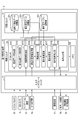
- FIG. 1 is a diagram showing an overall configuration of a vehicle 1 including a concentration degree determination device 2 according to an embodiment of the present invention.
- the concentration determination device 2 is mounted on a vehicle 1 such as a passenger car.
- the configuration of the concentration determination device 2 will be described later.
- the vehicle 1 may be, for example, any one of an automobile, a bus, a truck, a train, and the like, or a vehicle on which a driver (hereinafter also referred to as a driver) other than these rides.
- the vehicle 1 includes, as basic equipment, a power unit 3 including a power source and a transmission, a steering device 4 equipped with a steering wheel 5, and further includes a manual operation mode and an automatic operation mode as operation modes. .
- An engine and / or a motor is used as the power source.
- the manual driving mode is a mode in which the vehicle 1 is driven mainly by a driver's manual driving operation, for example.
- the manual driving mode for example, an operation mode for driving the vehicle 1 based only on the driving operation of the driver and an operation for performing driving operation support control for supporting the driving operation of the driver while mainly driving the driving operation of the driver. Mode is included.
- the driving operation support control assists the steering torque so that the driver's steering becomes an appropriate steering amount based on the curvature of the curve when the vehicle 1 is traveling on the curve, for example.
- the driving operation support control includes control for assisting a driver's accelerator operation (for example, operation of an accelerator pedal) or brake operation (for example, operation of a brake pedal), manual steering (manual operation of steering), and manual speed adjustment (speed). Adjustment manual operation) is also included.
- a driver's accelerator operation for example, operation of an accelerator pedal
- brake operation for example, operation of a brake pedal
- manual steering manual operation of steering
- speed manual speed adjustment
- Adjustment manual operation is also included.
- manual steering the vehicle 1 is steered mainly by the driver's operation of the steering wheel 5.
- the speed of the vehicle 1 is adjusted mainly by the driver's accelerator operation or brake operation.
- the driving operation support control does not include control for forcibly intervening in the driving operation of the driver to automatically drive the vehicle 1. That is, in the manual driving mode, the driving operation of the driver is reflected in the driving of the vehicle 1 within a preset allowable range, but the driving of the vehicle 1 is compulsory under certain conditions (for example, lane departure of the vehicle 1). Interventive control is not included.
- the automatic operation mode is a mode for realizing an operation state in which the vehicle 1 is automatically driven along the road on which the vehicle 1 is traveling, for example.
- the automatic driving mode includes, for example, a driving state in which the vehicle 1 is automatically driven toward a preset destination without driving by the driver.
- the automatic driving mode it is not always necessary to automatically control all of the vehicle 1, and the driving state in which the driving operation of the driver is reflected in the traveling of the vehicle 1 within a preset allowable range is also included in the automatic driving mode. That is, the automatic driving mode includes control for forcibly intervening in the traveling of the vehicle 1 under certain conditions, while reflecting the driving operation of the driver in the traveling of the vehicle 1 within a preset allowable range.
- the vehicle 1 further includes an outside camera 6, a steering sensor 7, an accelerator pedal sensor 8, a brake pedal sensor 9, a GPS receiver 10, a gyro sensor 11, a vehicle speed sensor 12, a navigation device 13, an automatic An operation control device 14, a driver camera 15, an audio output device 16, and a communication device 17 are provided.
- the outside camera 6 is installed at an arbitrary position of the vehicle 1 so that the outside of the vehicle 1 can be photographed.
- the vehicle 1 may include a plurality of vehicle exterior cameras that capture different directions.
- the outside camera 6 continuously captures the driving environment in the vicinity of the vehicle 1.
- the vehicle exterior camera 6 is activated in response to the start of operation of the vehicle 1 and continuously captures the outside of the vehicle 1.
- the outside camera 6 is an example of a sensor that monitors the outside of the vehicle 1.
- the vehicle exterior camera 6 outputs the captured image (hereinafter also referred to as vehicle exterior image data) to the concentration degree determination device 2 and the automatic driving control device 14.
- the steering sensor 7 detects a steering angle.
- the steering sensor 7 outputs the detection result to the automatic driving control device 14.
- the accelerator pedal sensor 8 detects an operation amount of the accelerator pedal.
- the accelerator pedal sensor 8 outputs the detection result to the automatic operation control device 14.
- the brake pedal sensor 9 detects the operation amount of the brake pedal.
- the brake pedal sensor 9 outputs the detection result to the automatic operation control device 14.
- the GPS receiver 10 receives current position information of the vehicle 1.
- the GPS receiver 10 outputs the current position information to the concentration determination device 2, the navigation device 13, and the automatic operation control device 14.
- the gyro sensor 11 detects the behavior of the vehicle 1.
- the gyro sensor 11 outputs the detection result to the automatic operation control device 14.
- the vehicle speed sensor 12 detects the speed of the vehicle 1.
- the vehicle speed sensor 12 outputs the detection result to the automatic driving control device 14.
- the navigation device 13 is an example of a video display device that includes a display 131 that displays video.
- the navigation device 13 stores map information.
- the navigation device 13 extracts route information from the current position to the destination by using information on the destination input by the driver or the like, map information, and current position information from the GPS receiver 10.
- the navigation device 13 displays route information on the display 131.
- the navigation device 13 can also display information other than route information on the display 131.
- the navigation device 13 outputs the route information to the concentration degree determination device 2 and the automatic driving control device 14.
- the route information described above may include not only information on the route from the current position to the destination, but also information on the road environment from the current position to the destination. Some examples of information about the road environment will be described.
- the information on the road environment may include information on the type of road that passes from the current position to the destination.
- the types of roads are classified into, for example, roads in which human traffic is restricted or roads in which human traffic is not restricted.
- the road where the passage of people is restricted is, for example, an expressway.
- the highway can also be called a motorway.
- the road where the passage of people is not restricted is, for example, a general road.
- the information on the road environment may include information on the speed limit of the road that passes from the current position to the destination.
- the information regarding the road environment may include position information of an installation on the road passing from the current position to the destination.
- the installed object is, for example, a sign, but may be an object installed on the road.
- the information regarding the road environment may include position information of a building near the road passing from the current position to the destination.
- Information about the road environment may include information on the number of lanes on the road.
- the information on the road environment may include information on the position of the curve section that passes between the current position and the destination.
- Information on the road environment may include information on the curvature of the curve in the curve section.
- the information on the road environment may include information on the gradient of the road that passes between the current position and the destination. Note that the route information may include information other than the above example as information on the road environment.
- the configuration of the automatic operation control device 14 will be described.
- the automatic operation control device 14 automatically controls traveling of the vehicle 1 when the operation mode is the automatic operation mode.
- the automatic driving control device 14 includes an outside image data from the outside camera 6, a detection result from the steering sensor 7, a detection result from the accelerator pedal sensor 8, a detection result from the brake pedal sensor 9, and a GPS receiver 10. Current position information, a detection result from the gyro sensor 11, a detection result from the vehicle speed sensor 12, and route information from the navigation device 13 are acquired.
- the automatic driving control device 14 automatically controls the traveling of the vehicle 1 based on these information and traffic information acquired by road-to-vehicle communication of the communication device 17 described later.
- Automatic control includes, for example, automatic steering (automatic steering operation) and automatic speed adjustment (automatic driving of speed).
- Automatic steering is an operating state in which the steering device 4 is automatically controlled.
- Automatic steering includes LKAS (Lane Keeping Assist System).
- the LKAS automatically controls the steering device 4 so that the vehicle 1 does not deviate from the traveling lane even when the driver does not perform the steering operation.
- the steering operation of the driver may be reflected in the steering of the vehicle 1 within a range (allowable range) in which the vehicle 1 does not deviate from the travel lane even during execution of LKAS.
- automatic steering is not limited to LKAS.
- Automatic speed adjustment is an operating state in which the speed of the vehicle 1 is automatically controlled.
- Automatic speed adjustment includes ACC (Adaptive Cruise Control). For example, when there is no preceding vehicle ahead of the vehicle 1, ACC performs constant speed control that causes the vehicle 1 to travel at a constant speed at a preset speed, and when the preceding vehicle exists ahead of the vehicle 1. Is a follow-up control that adjusts the vehicle speed of the vehicle 1 in accordance with the inter-vehicle distance from the preceding vehicle.
- the automatic operation control device 14 decelerates the vehicle 1 according to the driver's brake operation (for example, operation of the brake pedal) even when ACC is being executed.
- the automatic driving control device 14 can operate the driver's accelerator operation (for example, accelerator) up to a preset maximum permissible speed (for example, the maximum speed legally determined on the traveling road) even when ACC is being executed.
- the vehicle 1 can be accelerated according to the pedal operation.
- the automatic speed adjustment is not limited to ACC but also includes CC (Cruise Control).
- the configuration of the driver camera 15 will be described.
- the driver camera 15 is installed, for example, at a position that is in front of the driver as on a dashboard.
- the driver camera 15 is an example of a sensor that monitors a driver.
- the driver camera 15 is activated in response to the start of driving of the vehicle 1 and continuously captures a predetermined range including the driver's face.
- the driver camera 15 outputs the captured image (hereinafter referred to as driver image data) to the concentration degree determination device 2.
- Driver image data is an example of monitoring data used to detect the state of the driver.
- the driver's condition is, for example, driver's forward gaze, drowsiness, looking aside, putting on and taking off clothes, telephone operation, leaning on the window / armrest, driving disturbance by passengers and pets, onset of illness, backwards, kneeling, eating and drinking , Smoking, dizziness, abnormal behavior, car navigation / audio operation, attachment / detachment of glasses / sunglasses, photography, and a degree of recognition of a subject (a degree of recognition of a subject).
- the degree of recognition is an index of how much the driver has recognized the object (for example, visually), and is the degree to which the driver is conscious by confirming the object (for example, visually).
- the state of the driver may include an index other than the index exemplified here.
- the audio output device 16 includes a speaker 161.
- the audio output device 16 outputs various information as audio.
- the communication device 17 includes a vehicle-to-vehicle communication module 171 and a road-to-vehicle communication module 172.
- the inter-vehicle communication module 171 communicates directly with another vehicle by radio.
- the inter-vehicle communication module 171 transmits, for example, information related to the vehicle 1 to another vehicle close to the vehicle 1 by inter-vehicle communication.
- the information regarding the vehicle 1 is, for example, position information and speed information, but is not limited thereto.
- the inter-vehicle communication module 171 receives, for example, information on another vehicle that is close to the vehicle 1 from the other vehicle by inter-vehicle communication.
- the information regarding another vehicle is, for example, position information and speed information, but is not limited thereto.
- the road-to-vehicle communication module 172 communicates wirelessly with roadside devices installed on the road.
- the road-to-vehicle communication module 172 transmits, for example, information on the vehicle 1 to the roadside machine through road-to-vehicle communication.
- the road-to-vehicle communication module 172 receives various information exemplified below from the roadside machine through road-to-vehicle communication.
- the road-to-vehicle communication module 172 may receive, for example, information about another vehicle that is close to the vehicle 1 from the roadside machine.
- the road-to-vehicle communication module 172 may receive traffic information from a roadside machine, for example.
- the traffic information may include, for example, lane regulation information and closed information.
- the traffic information may include, for example, signal information related to the display of signals installed in the vicinity of the roadside machine.
- the road-to-vehicle communication module 172 may receive weather information from a roadside machine, for example.
- the road-vehicle communication module 172 may receive, for example, information on the presence / absence of a person crossing a road near the roadside machine from the roadside machine.
- the road-vehicle communication module 172 may receive information other than the information described above from the roadside machine.
- the communication device 17 outputs the information obtained by the vehicle-to-vehicle communication and the road-to-vehicle communication as described above to the concentration degree determination device 2 and the automatic driving control device 14.
- the concentration level determination device 2 estimates the driver's concentration level based on the above-described driver state, and determines whether or not the driver is in a state suitable for driving the vehicle 1.
- the driving concentration degree is a degree suitable for the driver to drive the vehicle 1. As the driving concentration increases, the driver becomes more suitable for driving the vehicle 1. Conversely, as the degree of driving concentration decreases, the driver becomes more unsuitable for driving the vehicle 1.
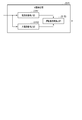
- FIG. 2 is a block diagram illustrating a configuration of the concentration determination device 2 as an example.
- the concentration degree determination device 2 includes an input / output interface unit 21, a storage unit 22, and a control unit 23.
- the input / output interface unit 21 connects the outside camera 6, the GPS receiver 10, the navigation device 13, the automatic operation control device 14, the driver camera 15, the audio output device 16, and the communication device 17 to the control unit 23.
- the configuration of the storage unit 22 will be described.
- the storage unit 22 is a non-volatile memory that can be written and read at any time, such as a solid state drive (SSD) and a hard disk drive (HDD).
- the storage unit 22 includes a driver image data storage unit 221, a vehicle exterior image data storage unit 222, and a concentration level table storage unit 223.
- the driver image data storage unit 221 stores driver image data that the control unit 23 acquires from the driver camera 15.
- the vehicle exterior image data storage unit 222 stores vehicle exterior image data that the control unit 23 acquires from the vehicle exterior camera 6.
- the concentration level table storage unit 223 stores a concentration level table used by the control unit 23 to estimate the driving concentration level.
- the concentration degree table associates the state of the driver with a plurality of levels corresponding to the degree of driving concentration for each index.
- the plurality of levels are divided into, for example, three levels of level 1, level 2, and level 3, but the present invention is not limited to this.
- the driving concentration is set to be lower as the level number is larger, but the present invention is not limited to this. It may be set such that the driving concentration increases as the level number increases.
- Level 1 is associated with, for example, the state of a driver who is looking at a direction tilted at an angle in the range of 0 degrees or more and less than the first angle with respect to the traveling direction of the vehicle 1. That is, Level 1 is a state in which the driver is not looking aside and driving concentration is high.
- Level 2 is associated with, for example, the state of the driver who is looking at a direction tilted at an angle in the range of the first angle and less than the second angle with respect to the traveling direction of the vehicle 1.
- Level 2 is a state in which the driver is looking aside and has a lower driving concentration than Level 1.
- Level 3 is associated with, for example, the state of the driver who is looking at a direction inclined at an angle equal to or greater than the second angle with respect to the traveling direction of the vehicle 1. That is, Level 3 is a state in which the driver is looking aside and the driving concentration is lower than Level 2.
- the information managed in the concentration level table has been described by taking a side look as an example, but the same applies to other indexes.
- the configuration of the control unit 23 will be described.
- the control unit 23 includes a processor 231 and a memory 232.
- the processor 231 is, for example, a CPU (Central Processing Unit) that constitutes a computer.
- the configuration of each unit included in the processor 231 will be described later. Note that although one processor 231 is shown in FIG. 2, the control unit 23 may include one or more processors.
- the memory 232 includes a program that causes the processor 231 to function as each unit included in the processor 231.
- the program can also be referred to as an instruction for operating the processor 231.
- the program is stored in the storage unit 22 and is read from the storage unit 22 to the memory 232.
- the program in the memory 232 is read by the processor 231.
- One embodiment may be realized by a program.
- the processor 231 includes a monitoring data acquisition unit 2311, a vehicle exterior image data acquisition unit 2312, a route information acquisition unit 2313, a current position information acquisition unit 2314, a state detection unit 2315, a concentration degree estimation unit 2316, and a reference comparison unit. 2317, a traveling state detection unit 2318, and a signal output unit 2319. Each unit may be distributed among one or more processors.
- the monitoring data acquisition unit 2311 acquires driver image data from the driver camera 15 via the input / output interface unit 21.
- the monitoring data acquisition unit 2311 stores the driver image data in the driver image data storage unit 221.
- the vehicle exterior image data acquisition unit 2312 acquires vehicle exterior image data from the vehicle exterior camera 6 via the input / output interface unit 21.
- the vehicle exterior image data acquisition unit 2312 stores the vehicle exterior image data in the vehicle exterior image data storage unit 222.
- the route information acquisition unit 2313 acquires route information from the navigation device 13 via the input / output interface unit 21.
- the route information acquisition unit 2313 outputs the route information to the state detection unit 2315 and the traveling state detection unit 2318.
- the current position information acquisition unit 2314 acquires current position information from the GPS receiver 10 via the input / output interface unit 21.
- the current position information acquisition unit 2314 outputs the current position information to the state detection unit 2315 and the traveling state detection unit 2318.
- the state detection unit 2315 detects the state of the driver from the driver image data stored in the driver image data storage unit 221. In addition to the driver image data, the state detection unit 2315 detects, for example, the above-described object recognition degree as the driver's state using at least one of image data outside the vehicle, route information, and current position information. Also good. An example of detection of the driver's state by the state detection unit 2315 will be described later. Note that the state detection unit 2315 may acquire the driver image data from the monitoring data acquisition unit 2311 without using the driver image data storage unit 221. In this case, the storage unit 22 may not include the driver image data storage unit 221. The state detection unit 2315 outputs the driver's state to the concentration degree estimation unit 2316.
- the concentration level estimation unit 2316 estimates the driver's driving concentration level based on the driver's state detected by the state detection unit 2315. Note that since the driver's state is detected from the driver image data as described above, the concentration degree estimation unit 2316 can estimate the driver's driving concentration degree from the driver image data.
- the concentration degree estimation unit 2316 estimates a driving concentration degree corresponding to each of one or more indexes included in the driver's state.
- the concentration level estimation unit 2316 estimates, for example, the driving concentration level using sleepiness as an index, and also estimates the driving concentration level using a side look as an index. Note that the concentration degree estimation unit 2316 may estimate a single driving concentration degree based on, for example, a plurality of indexes included in the driver's state. In this case, the concentration degree estimation unit 2316 may estimate a single driving concentration degree by appropriately weighting each index. The weight set for each index may be arbitrarily changed.
- the concentration degree estimation unit 2316 can estimate the driving concentration degree by a numerical value such as a ratio.
- the numerical value estimated by the concentration degree estimation unit 2316 may increase as the driving concentration degree increases, or may decrease as the driving concentration degree increases.
- the concentration degree estimation unit 2316 refers to the concentration degree table stored in the concentration degree table storage unit 223 and estimates the level of driving concentration corresponding to the driver's state from a plurality of levels. be able to. Note that when the concentration level estimation unit 2316 estimates the driving concentration level numerically, the storage unit 22 may not include the concentration level table storage unit 223.
- the estimation of the driving concentration by the concentration estimating unit 2316 may be performed using an AI (Artificial Intelligence) function such as machine learning or deep learning.
- AI Artificial Intelligence
- the concentration degree estimation unit 2316 can estimate the state of the driver with high accuracy by using the past estimation result for estimation of the current driving concentration degree, for example.
- the reference comparison unit 2317 compares the driving concentration level estimated by the concentration level estimation unit 2316 with the reference.
- the reference comparison unit 2317 may compare the driving concentration level for each of the plurality of indexes with the reference.
- the concentration level estimation unit 2316 estimates a single driving concentration level based on a plurality of indices
- the reference comparison unit 2317 may compare the single driving concentration level with a reference.
- the reference comparison unit 2317 compares, for example, the driving concentration degree estimated by the concentration degree estimation unit 2316 with a reference value or reference level serving as a reference.
- the reference comparison unit 2317 determines that the driving concentration degree satisfies the reference.
- the reference comparison unit 2317 outputs the comparison result to the signal output unit 2319. Note that the reference may be arbitrarily changed.
- the comparison between the driving concentration degree estimated by the numerical value by the reference comparison unit 2317 and the reference will be described.
- the reference value is a numerical value A. If the numerical value estimated by the concentration degree estimation unit 2316 is smaller than the numerical value A, which is the reference value, the reference comparison unit 2317 determines that the driving concentration degree estimated by the concentration degree estimation unit 2316 is lower than the reference value.
- the reference comparison unit 2317 determines that the driving concentration degree estimated by the concentration degree estimation unit 2316 is lower than the reference value.
- the reference level is level B extracted from a plurality of levels.
- the reference comparing unit 2317 indicates that the driving concentration degree estimated by the concentration degree estimating unit 2316 is the reference level. Judged to be lower than the level.
- the concentration level table associates the state of the driver with the three levels of Level 1, Level 2, and Level 3 for each index.
- the reference level is level 1.
- the reference comparison unit 2317 determines that level 2 or level 3 estimated by the concentration degree estimation unit 2316 is lower than level 1, which is the reference level.
- the reference comparison unit 2317 determines that the level 1 estimated by the concentration degree estimation unit 2316 is not lower than the level 1 that is the reference level.
- the driving state detection unit 2318 detects a position where the driving state of the vehicle 1 changes (hereinafter also referred to as a driving state change position) when the driving mode of the vehicle 1 is the automatic driving mode.
- a driving state change position a position where the driving state of the vehicle 1 changes
- the change in the running state is, for example, the behavior of the vehicle 1 in which at least one of the acceleration in the traveling direction of the vehicle 1 and the acceleration in the direction orthogonal to the traveling direction changes by a predetermined amount or more or a predetermined ratio.
- the predetermined amount or the predetermined ratio may be arbitrarily changed.
- the change in the running state may be evaluated by data other than acceleration.
- the change in the running state may cause, for example, a change in vehicle behavior (yawing, rolling, pitching). The driver is surprised when the vehicle behavior changes more than a certain level in a state where the driving concentration is low.
- the change in the running state of the vehicle 1 is not particularly limited, and is, for example, acceleration, deceleration, stop, lane change, entry into a curve section, right turn or left turn of the vehicle 1.
- the right turn or left turn may include a U-turn.
- the change in the running state of the vehicle 1 may be switching between forward and reverse.
- the change in the running state of the vehicle 1 may be a change in the uneven state of the road surface.
- the change in the uneven state of the road surface is, for example, an uneven road, a rough road, an unpaved road, an approach to a road under construction, or the like.
- the traveling state detection unit 2318 further monitors that the vehicle 1 reaches a position X before the traveling state change position.
- the traveling state detection unit 2318 detects that the vehicle 1 has reached the position X
- the traveling state detection unit 2318 outputs a detection result indicating that the vehicle 1 has reached the position X to the signal output unit 2319.
- the position X is a position where the signal output unit 2319 outputs an instruction signal instructing the driver to execute a predetermined notification output, as will be described later. Therefore, the position X is not particularly limited as long as it is between the current position of the vehicle 1 and the traveling state change position, but is preferably near the traveling state change position.
- the position X may be a position where the distance to the traveling state change position is a predetermined distance, for example.
- the predetermined distance may be arbitrarily changed.
- the traveling state detection unit 2318 may monitor that the vehicle 1 reaches the position X as in the following example.
- the traveling state detection unit 2318 sets a position X that is a predetermined distance returned from the traveling state change position to the current position side of the vehicle 1 as a position X.
- the traveling state detection unit 2318 compares the current position of the vehicle 1 with the position X, and monitors that the vehicle 1 reaches the position X.
- the position X may be, for example, a position where the vehicle 1 is estimated to reach the traveling state change position after a predetermined time.
- the predetermined time may be arbitrarily changed.
- the traveling state detection unit 2318 may monitor that the vehicle 1 reaches the position X as in the following example.
- the traveling state detection unit 2318 refers to the speed of the vehicle 1 and sets, as the position X, a position where the vehicle 1 is estimated to reach the traveling state change position after a predetermined time.
- the traveling state detection unit 2318 compares the current position of the vehicle 1 with the position X, and monitors that the vehicle 1 reaches the position X.
- the travel state detection unit 2318 refers to the speed of the vehicle 1 and estimates the time when the vehicle 1 reaches the travel state change position (hereinafter also referred to as change position arrival time).
- the traveling state detection unit 2318 sets the time when the vehicle 1 passes the position X as the time returned from the change position arrival time by a predetermined time.
- the traveling state detection unit 2318 compares the time when the vehicle 1 passes the position X with the current time, and monitors that the vehicle 1 reaches the position X.
- the configuration of the signal output unit 2319 will be described.
- the signal output unit 2319 outputs a signal to each unit via the input / output interface unit 21.
- examples of some signals output from the signal output unit 2319 will be described.
- the signal output unit 2319 When the driving mode is the automatic driving mode and the driving concentration does not satisfy the standard, the signal output unit 2319 outputs the above instruction signal before the vehicle 1 reaches the traveling state change position.
- the signal output unit 2319 can recognize that the operation mode is the automatic operation mode, for example, as follows.
- the concentration degree determination device 2 may receive a signal from the automatic operation control device 14 when the operation mode is switched from the manual operation mode to the automatic operation mode.
- the signal output unit 2319 can recognize that the operation mode is the automatic operation mode based on the signal from the automatic operation control device 14.
- the signal output unit 2319 can recognize based on the comparison result from the reference comparison unit 2317 that the driving concentration does not satisfy the standard.
- the signal output unit 2319 can recognize that the vehicle 1 has reached the position X before the travel state change position based on the detection result from the travel state detection unit 2318.
- the signal output unit 2319 outputs an instruction signal instructing the driver to execute a predetermined notification output based on reception of the detection result from the traveling state detection unit 2318. Thereby, the signal output unit 2319 can output an instruction signal before the vehicle 1 reaches the traveling state change position.
- the notification providing apparatus receives the instruction signal from the signal output unit 2319, the notification providing apparatus outputs a predetermined notification to the driver.
- the notification providing device is, for example, the navigation device 13 and the audio output device 16.
- the navigation device 13 displays, on the display 131, an image or video notification that informs the driver of changes in the driving state based on the instruction signal, for example.
- the audio output device 16 outputs, for example, a notification that informs the driver of changes in the running state from the speaker 161.
- the notification is not limited as long as it is a content that informs the driver of changes in the driving state or changes in the vehicle behavior or prompts a response to such changes.
- the driver can recognize from the notification that the vehicle 1 is approaching the travel state change position, and can prepare for a change in the travel state or a change in the vehicle behavior.
- the signal output unit 2319 may output the instruction signal to a device other than the navigation device 13 and the voice output device 16.
- the signal output unit 2319 may output an instruction signal to a notification providing apparatus that gives an external stimulus such as vibration to the driver as a notification.
- the signal output unit 2319 can output an instruction signal when one or more driving concentration degrees out of a plurality of driving concentration degrees estimated from a plurality of indices do not satisfy the standard.
- the signal output unit 2319 may output an instruction signal when a predetermined number or more of the driving concentration degrees estimated from the plurality of indexes do not satisfy the standard.
- the signal output unit 2319 may output an instruction signal when a single degree of driving concentration estimated based on a plurality of indices does not satisfy the standard.
- the signal output unit 2319 may output a switching signal for switching the operation mode to the automatic operation control device 14.
- FIG. 3 is a block diagram illustrating a configuration of the state detection unit 2315.
- the state detection unit 2315 includes a local state detection unit 23151, a global state detection unit 23152, and a driver state detection unit 23153.
- the local state detection unit 23151 detects the state of at least one of the organs included in the driver's face in the driver image data.
- the organs included in the face are, for example, the eyes, mouth, nose and ears, but other organs may be used.
- the local state detection unit 23151 detects an eye state
- the local state detection unit 23151 detects, for example, a driver's eye open / closed degree, a line-of-sight direction, a face direction, and the like.
- Local state detection unit 23151 outputs a detection result (hereinafter also referred to as local information) to driver state detection unit 23153.
- the global state detection unit 23152 detects at least one of the global states of the driver in the driver image data.
- the global state is, for example, the movement and posture of the driver, but may be other than these.
- the global state detection unit 23152 outputs a detection result (hereinafter also referred to as global information) to the driver state detection unit 23153.
- the driver state detection unit 23153 detects the above-described driver state using the local information from the local state detection unit 23151 and the global information from the global state detection unit 23152.
- the state detection unit 2315 can detect various driver states by combining local information and global information, for example.
- the state detection unit 2315 can detect the degree of object recognition using the monitoring data and the position information of the object.
- the state detection unit 2315 can detect the degree of object recognition by the driver's vision using the image data outside the vehicle in addition to the driver image data as follows.
- the state detection unit 2315 extracts a target for detecting the degree of object recognition from the image data outside the vehicle.
- the target is, for example, an installation such as a sign or a building, but is not particularly limited as long as the driver may confirm (for example, visually) and be aware of it.
- the state detection unit 2315 detects the driver's line of sight and face orientation from the driver image data captured at substantially the same timing as when the image data outside the vehicle from which the target was extracted was captured.
- the driver's line of sight and face orientation are detected by the local state detection unit 23151 as described above.
- the state detection unit 2315 detects the degree of object recognition using at least one of the driver's line of sight and face orientation and the position information of the object. It can be said that the degree of object recognition increases as the driver's line of sight and face direction face the object.
- the state detection unit 2315 has a high degree of object recognition on condition that at least one of the driver's line of sight and face orientation is in a state that matches the position of the object for a predetermined time. It may be detected. On the other hand, when at least one of the driver's line of sight and face orientation is directed to the target position but passes without recognizing the target, the state detection unit 2315 detects that the degree of target recognition is low. May be. The state detection unit 2315 may detect the degree of object recognition in accordance with the length of time that the driver stays in a state where at least one of the driver's line of sight and face orientation matches the target position.
- the state detection unit 2315 may estimate the degree of object recognition based on the presence or absence of a specific driving operation or a driver's action that is assumed to result from the driver's recognition of the object. For example, when the driver recognizes that a pedestrian is present near the pedestrian crossing in front of the vehicle 1, it is assumed that the driver performs a deceleration operation. Therefore, when the concentration determination device 2 detects that a pedestrian is present near the pedestrian crossing in front of the vehicle 1, the state detection unit 2315 detects the driver's deceleration operation, and the degree of object recognition is You may detect that it is high.
- the state detection unit 2315 detects the driver's deceleration operation even after a predetermined time has elapsed. If not, it may be detected that the degree of object recognition is low. For example, depending on the length of time from when the concentration determination device 2 detects a target pedestrian until the driver's deceleration operation is detected, the state detection unit 2315 may detect the target recognition degree. Good.
- the state detection unit 2315 can detect the degree of object recognition using route information and current position information in addition to driver image data as follows.
- the state detection unit 2315 refers to the route information and the current position information and extracts a target located in the vicinity of the vehicle 1.
- the target is, for example, an installation such as a sign or a building, but is not particularly limited as long as the driver may confirm (for example, visually) and recognize it.
- the state detection unit 2315 detects the driver's line of sight and the direction of the face from the driver image data captured at substantially the same timing as when the vehicle 1 passes through the vicinity of the target.
- the state detection unit 2315 detects the degree of object recognition using at least one of the driver's line of sight and face orientation and the position information of the object.
- the state detection unit 2315 may obtain the target position and the timing at which the vehicle 1 passes near the target through road-to-vehicle communication. In this case, the state detection unit 2315 detects the driver's line of sight and face direction from the driver image data captured at substantially the same timing as the vehicle 1 passes through the vicinity of the target. The state detection unit 2315 detects the degree of object recognition using at least one of the driver's line of sight and face orientation and the position information of the object.
- the state detection unit 2315 may use an image or video displayed on the display 131 of the navigation device 13 as a target. In this case, the state detection unit 2315 detects the driver's line of sight and face direction from the driver image data captured at substantially the same timing as when the image or video is displayed on the display 131. The state detection unit 2315 detects the degree of object recognition using at least one of the driver's line of sight and face orientation and the position information of the object.
- the state detection unit 2315 can appropriately detect the driver's state using the degree of object recognition as an index.
- the state detection unit 2315 may use an object located in the vicinity of the front, rear, left, or right of the vehicle 1.
- the state detection unit 2315 preferably uses an object located near the left side or the right side rather than the front side of the vehicle 1. If the object is located on the front side of the vehicle 1, the driver's line of sight and face do not move much. On the other hand, if the object is located near the left side or right side of the vehicle 1, the driver's line of sight and face move to the left or right side. Therefore, the state detection unit 2315 can appropriately detect the target recognition degree.
- the traveling state detection unit 2318 may detect the traveling state change position by a method other than the detection example shown here. As an example, the traveling state detection unit 2318 may use the route information of the vehicle 1 acquired from the navigation device 13 via the route information acquisition unit 2313. The travel state detection unit 2318 can detect a travel state change position on a route on which the vehicle 1 is to travel based on various information included in the route information of the vehicle 1. Hereinafter, several detection examples of the traveling state change position based on the route information of the vehicle 1 will be described.
- the traveling state detection unit 2318 may detect the traveling state change position based on, for example, speed limit information included in the route information. For example, the traveling state detection unit 2318 may detect or estimate the vicinity of a position where sections having different speed limits are adjacent as a position where acceleration or deceleration of the vehicle 1 occurs. If the difference between the speed limits of adjacent sections is equal to or less than a predetermined value, the traveling state detection unit 2318 may not detect the vicinity of the position where the sections with different speed limits are adjacent as the traveling state change position. The reason is that even if the speed limit changes, the change in the running state of the vehicle 1 is small.
- the traveling state detection unit 2318 may detect a traveling state change position based on, for example, gradient information included in the route information. For example, the traveling state detection unit 2318 may detect or estimate the vicinity of a position where sections with different gradients are adjacent as a position where acceleration or deceleration of the vehicle 1 occurs. If the difference in gradient between adjacent sections is equal to or less than a predetermined value, the traveling state detection unit 2318 may not detect the vicinity of a position where adjacent sections with different gradients are adjacent as the traveling state change position. The reason is that even if the gradient changes, the change in the running state of the vehicle 1 is small.
- the traveling state detection unit 2318 may detect the traveling state change position based on, for example, information on a route included in the route information. For example, the traveling state detection unit 2318 may detect or estimate the destination as a position where the stop of the vehicle 1 occurs.
- the traveling state detection unit 2318 may detect the traveling state change position based on, for example, information on a route included in the route information. For example, the traveling state detection unit 2318 may detect or estimate the position near the interchange where the vehicle 1 gets off the highway as the position where the lane change of the vehicle 1 occurs.
- the traveling state detection unit 2318 may detect the traveling state change position based on, for example, information on the position of the curve section included in the route information. For example, the traveling state detection unit 2318 may detect or estimate the start position of the curve section as a position where the vehicle 1 enters the curve section. If the curvature of the curve section is equal to or less than the predetermined value, the traveling state detection unit 2318 may not detect the curve section as the traveling state change position. The reason is that even if the vehicle 1 enters a curve section with a small curvature, the change in the running state of the vehicle 1 is small.
- the traveling state detection unit 2318 may detect the traveling state change position based on, for example, information on a route included in the route information. For example, the traveling state detection unit 2318 may detect or estimate a position where the traveling direction of the vehicle 1 changes by a predetermined angle or more as a position where the vehicle 1 turns right or left.
- the traveling state detection unit 2318 may detect the traveling state change position based on, for example, information on the road surface state of the road included in the road environment information.
- the information regarding the road surface condition of the road is, for example, information about an unpaved section and a section under road surface construction.
- the traveling state detection unit 2318 can detect the uneven state of the road surface based on, for example, information on the road surface state of the road.
- the traveling state detection unit 2318 may detect or estimate a position where a change in the uneven state of the road surface occurs based on detection of the uneven state of the road surface.
- the traveling state detection unit 2318 may detect the traveling state change position based on position information such as a parking lot included in the route information, for example. For example, the traveling state detection unit 2318 may detect or estimate a position such as a parking lot as a position where the vehicle 1 is switched between forward and reverse. Note that the traveling state detection unit 2318 may detect the forward / backward switching of the vehicle 1 that is the content of the change in the traveling state based on the vehicle control information by the parking device or the like.
- the traveling state detection unit 2318 may use information obtained from the communication device 17.
- the traveling state detection unit 2318 can detect the traveling state change position based on information obtained from at least one of inter-vehicle communication and road-to-vehicle communication.
- the traveling state detection unit 2318 detects the position of the vehicle that interferes with the traveling of the vehicle 1 based on, for example, information on another vehicle obtained by inter-vehicle communication or road-to-vehicle communication.
- the traveling state detection unit 2318 can detect the vicinity of the position of the vehicle that interferes with traveling of the vehicle 1 as the traveling state change position.
- the traveling state detection unit 2318 detects the position of a person who interferes with the traveling of the vehicle 1 based on, for example, information on the presence or absence of a person who crosses a road in the vicinity of a roadside machine obtained by road-to-vehicle communication.
- the traveling state detection unit 2318 can detect the vicinity of the position of a person who interferes with traveling of the vehicle 1 as the traveling state change position.
- the traveling state detection unit 2318 detects a lane-restricted position or a closed position based on traffic information obtained by road-to-vehicle communication, for example.
- the travel state detection unit 2318 can detect a lane-restricted position or a closed position as the travel state change position.
- the traveling state detection unit 2318 may detect or estimate how the traveling state changes at the traveling state change position with reference to various information.
- the traveling state detection unit 2318 may use, for example, information on the road environment included in the distance and route information from the current position of the vehicle 1 to the traveling state change position.
- the road environment information is, for example, the number of lanes on the road on which the vehicle 1 is traveling, but is not limited thereto.
- the traveling state detection unit 2318 detects or estimates acceleration, deceleration, stop, lane change, entry into a curve section, right turn or left turn at the traveling state change position.
- the traveling state detection unit 2318 may use data acquired from a sensor that monitors the outside of the vehicle 1.
- the traveling state detector 2318 can detect the traveling state change position based on data taken from a sensor that monitors the outside of the vehicle 1.
- the case where the sensor for monitoring the outside of the vehicle 1 is the outside camera 6 will be described as an example.
- the sensor that monitors the outside of the vehicle 1 is not limited to the outside camera 6.
- the sensor that monitors the outside of the vehicle 1 may be, for example, a radar that detects an object located in the vicinity of the vehicle 1 by radio waves.
- the traveling state detection unit 2318 detects an object (hereinafter simply referred to as an object) that hinders the traveling of the vehicle 1 and a distance from the vehicle 1 to the object from the image data outside the vehicle.
- the object include, but are not limited to, a vehicle stopped due to a failure or an accident, a fallen object, and the like.
- the traveling state detection unit 2318 can detect the vicinity of the position of the object as the traveling state change position.
- the traveling state detection unit 2318 may detect a person who interferes with the traveling of the vehicle 1 from the image data outside the vehicle.
- the person who interferes with the traveling of the vehicle 1 is, for example, a person who crosses the front of the vehicle 1.
- the traveling state detection unit 2318 may detect or estimate how the traveling state changes at the traveling state change position with reference to various information.
- the traveling state detection unit 2318 may use, for example, information on the road environment included in the distance and route information from the current position of the vehicle 1 to the traveling state change position.
- the road environment information is, for example, the number of lanes on the road on which the vehicle 1 is traveling, but is not limited thereto.
- the traveling state detection unit 2318 detects or estimates acceleration, deceleration, stop, lane change, entry into a curve section, right turn or left turn at the traveling state change position.
- the traveling state detection unit 2318 may detect the traveling state change position by combining two or more of route information, information obtained from the communication device 17, and image data outside the vehicle, for example.
- the traveling state detection unit 2318 may detect the traveling state change position based on route information and weather information included in traffic information obtained from the communication device 17.
- the traveling state detection unit 2318 may detect more traveling state change positions than when the weather is clear.
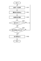
- FIG. 4 is a flowchart showing a procedure as an example of concentration level determination by the concentration level determination device 2 when the operation mode is the automatic operation mode.
- the monitoring data acquisition unit 2311 acquires monitoring data from a sensor that monitors the driver of the vehicle 1 (step S101). In step S ⁇ b> 101, the monitoring data acquisition unit 2311 acquires driver image data from the driver camera 15 via, for example, the input / output interface unit 21. Note that the interval at which the monitoring data acquisition unit 2311 acquires the monitoring data may be the same as or shorter than the interval at which the state detection unit 2315 detects the driver's state.
- the state detection unit 2315 detects the driver's state from the monitoring data (step S102).
- the state detection unit 2315 detects the state of the driver from the driver image data, for example.
- the state detection unit 2315 can detect the state of the driver at a predetermined interval, for example.
- the state detection unit 2315 may detect the state of the driver at an arbitrary timing.
- the concentration degree estimation unit 2316 estimates the driver's driving concentration degree from the monitoring data (step S103).
- the concentration degree estimation unit 2316 estimates the driving concentration degree based on the state of the driver detected from the driver image data by the state detection unit 2315, for example.
- the reference comparison unit 2317 compares the driving concentration with the reference (step S104).
- the processing of the concentration degree determination device 2 may transition from step S104 to step S101.
- the traveling state detection unit 2318 determines whether the vehicle 1 is close to the traveling state change position (Step S105). In step S105, for example, when the traveling state detection unit 2318 determines that the vehicle 1 has reached the position X, it determines that the vehicle 1 is close to the traveling state change position. For example, when it is determined that the vehicle 1 has not reached the position X, the traveling state detection unit 2318 determines that the vehicle 1 is not close to the traveling state change position.
- Step S105 the processing of the concentration degree determination device 2 may transition from Step S105 to Step S101.
- step S105 Yes
- the signal output unit 2319 outputs an instruction signal (step S106). That is, in step S106, when the driving mode is the automatic driving mode and the driving concentration does not satisfy the standard, the signal output unit 2319 outputs an instruction signal before the vehicle 1 reaches the traveling state change position. To do.
- the concentration degree estimation part 2316 may be made to estimate a driving concentration degree using a driver
- the concentration degree estimation unit 2316 may estimate the driving concentration degree using only the driver's eating and drinking as an index.
- the concentration degree estimation unit 2316 may estimate a single driving concentration degree based on a combination of the driver's eating and drinking and one or more other indicators. For example, when the driver is eating and drinking, the concentration degree estimation unit 2316 estimates that the driving concentration degree is lower than that when the driver is not eating and drinking.
- the concentration determination device 2 determines that the vehicle 1 is in the driving state change position.
- An instruction signal can be output before reaching.
- the driver can recognize that the vehicle 1 is approaching the traveling state change position by the notification based on the instruction signal. Therefore, before the vehicle 1 reaches the travel state change position, the driver can prepare for the behavior of the vehicle 1 at the travel state change position, such as stopping eating and drinking. Even if the vehicle 1 passes the travel state change position, the driver does not spill food or drink. Therefore, the driver can ride on the vehicle 1 comfortably.
- the traveling state detection unit 2318 may detect the traveling state change position using the route information as described above. According to this example, the traveling state detection unit 2318 can detect the traveling state change position on the route on which the vehicle 1 is traveling with high accuracy. Furthermore, the traveling state detection unit 2318 can detect with high accuracy how the traveling state changes at the traveling state change position.
- the traveling state detection unit 2318 may detect the traveling state change position using the information acquired from the communication device 17 as described above. According to this example, the traveling state detection unit 2318 can detect a traveling state change position based on a sudden event that occurs in the vicinity of the vehicle 1 or on a route on which the vehicle 1 is scheduled to travel. Therefore, the traveling state detection unit 2318 can detect a traveling state change position that cannot be detected from the route information.
- the traveling state detection unit 2318 may detect the traveling state change position using data acquired from a sensor that monitors the outside of the vehicle 1 as described above. According to this example, the traveling state detection unit 2318 can detect a traveling state change position based on a sudden event that occurs in the vicinity of the vehicle 1. Therefore, the traveling state detection unit 2318 can detect a traveling state change position that cannot be detected from the route information.
- the change in the travel state detected or estimated by the travel state detection unit 2318 in step S105 is not particularly limited.
- the vehicle 1 may be accelerated, decelerated, stopped, changed lanes, entered into a curve section, turned right or left. There may be.
- the concentration degree determination device 2 can detect a change in the driving state that easily affects the driver's posture. Even if the vehicle passes through the travel state change position, the driver is not surprised or distracted by the change in the travel state of the vehicle.
- the signal output unit 2319 may include the content of the change in the running state detected or estimated by the running state detection unit 2318 in the instruction signal.
- the driver can recognize not only that the vehicle 1 is approaching the travel state change position but also how the travel state changes at the travel state change position.
- the driver can take a posture corresponding to a change in the running state.
- the concentration degree determination device 2 determines that the vehicle 1 is in the running state change position when the operation mode is the automatic operation mode and the operation concentration degree does not satisfy the standard.
- An instruction signal can be output before reaching.
- the driver can recognize that the vehicle 1 is approaching the traveling state change position by the notification based on the instruction signal. Therefore, before the vehicle 1 reaches the traveling state change position, the driver can prepare for the behavior of the vehicle 1 at the traveling state change position. Even if the vehicle 1 passes through the travel state change position, the driver will not be surprised or distracted by the change in the travel state of the vehicle 1.
- the concentration determination device 2 does not output an instruction signal. If the driving concentration satisfies the standard, it can be said that the driver pays attention to the environment outside the vehicle 1. If the vehicle 1 approaches the running state change position, the driver can easily recognize the running state change position. Therefore, the driver can prepare for the behavior of the vehicle 1 at the traveling state change position without receiving notification.
- the concentration degree determination device 2 can consider driving comfort in the automatic driving mode.
- the concentration determination device 2 detects the driver's state by using the driver image data captured by the driver camera 15 as monitoring data, and estimates the driving concentration.
- the monitoring data is not limited to the driver image data.
- the monitoring data may be, for example, biological data obtained by a biological sensor that monitors the driver of the vehicle 1.
- the biological sensor is, for example, a pulse wave sensor or a heart rate sensor.
- the biological sensor is not limited to these as long as it can monitor the driver.
- the biological sensor may be a contact sensor or a non-contact sensor.
- the concentration degree determination device 2 can detect the state of the driver from the biological data.
- the state of the driver detected from the biological data is an index such as a pulse wave or a heartbeat.
- the monitoring data may be, for example, data obtained by a sensor that measures the strength of the driver's steering wheel 5 installed on the steering wheel 5.
- the present invention is not limited to the above-described embodiment as it is, and can be embodied by modifying the constituent elements without departing from the scope of the invention in the implementation stage.
- various inventions can be formed by appropriately combining a plurality of constituent elements disclosed in the embodiment. For example, some components may be deleted from all the components shown in the embodiment. Furthermore, you may combine the component covering different embodiment suitably.
- the above embodiment may be realized by a storage medium such as a ROM (Read Only Memory) that stores a program that causes the processor 231 to function as each unit included in the processor 231.
- a storage medium such as a ROM (Read Only Memory) that stores a program that causes the processor 231 to function as each unit included in the processor 231.
- a processor configured to output an instruction signal indicating the output of A memory for storing instructions for operating the processor;
Abstract
La présente invention a pour objet de prendre en compte le confort de conduite. Un dispositif de détermination de degré de concentration comprend : une unité d'acquisition de données de surveillance pour acquérir des données de surveillance en provenance d'un capteur afin de surveiller le conducteur d'un véhicule; une unité d'estimation de degré de concentration pour estimer le degré de concentration de conduite du conducteur à partir des données de surveillance; une unité de comparaison de valeur standard pour comparer le degré de concentration de conduite à une valeur standard; une unité de détection d'état de marche qui, si le mode de conduite du véhicule est réglé sur un mode de conduite automatique, détecte un emplacement auquel l'état de marche du véhicule change; et une unité de sortie de signal qui, si le mode de conduite est réglé sur le mode de conduite automatique mode et si le degré de concentration de conduite ne satisfait pas la valeur standard, délivre en sortie un signal de commande pour commander au conducteur de délivrer une notification prescrite avant que le véhicule atteigne l'emplacement auquel l'état de marche change.
Applications Claiming Priority (2)
| Application Number | Priority Date | Filing Date | Title |
|---|---|---|---|
| JP2017048153A JP2018151902A (ja) | 2017-03-14 | 2017-03-14 | 集中度判定装置、集中度判定方法及び集中度判定のためのプログラム |
| JP2017-048153 | 2017-03-14 |
Publications (1)
| Publication Number | Publication Date |
|---|---|
| WO2018168099A1 true WO2018168099A1 (fr) | 2018-09-20 |
Family
ID=63522866
Family Applications (1)
| Application Number | Title | Priority Date | Filing Date |
|---|---|---|---|
| PCT/JP2017/042567 WO2018168099A1 (fr) | 2017-03-14 | 2017-11-28 | Dispositif de détermination de degré de concentration, procédé de détermination de degré de concentration et programme pour déterminer le degré de concentration |
Country Status (2)
| Country | Link |
|---|---|
| JP (1) | JP2018151902A (fr) |
| WO (1) | WO2018168099A1 (fr) |
Cited By (1)
| Publication number | Priority date | Publication date | Assignee | Title |
|---|---|---|---|---|
| CN110222421A (zh) * | 2019-06-06 | 2019-09-10 | 优必爱信息技术(北京)有限公司 | 一种行驶路线集中度评估方法及系统 |
Families Citing this family (1)
| Publication number | Priority date | Publication date | Assignee | Title |
|---|---|---|---|---|
| DE112019007558T5 (de) * | 2019-09-19 | 2022-05-19 | Mitsubishi Electric Corporation | Kognitiv-Funktion-Abschätzungsvorrichtung, Lernvorrichtung und Verfahren zur Schätzung der kognitiven Funktion |
Citations (3)
| Publication number | Priority date | Publication date | Assignee | Title |
|---|---|---|---|---|
| JP2011210103A (ja) * | 2010-03-30 | 2011-10-20 | Mazda Motor Corp | ドライバー状態判定装置 |
| JP2015047983A (ja) * | 2013-09-02 | 2015-03-16 | トヨタ自動車株式会社 | 運転特性判定装置及び運転特性判定方法 |
| JP2016153960A (ja) * | 2015-02-20 | 2016-08-25 | トヨタ自動車株式会社 | 運転支援装置 |
Family Cites Families (1)
| Publication number | Priority date | Publication date | Assignee | Title |
|---|---|---|---|---|
| WO2016052507A1 (fr) * | 2014-09-30 | 2016-04-07 | エイディシーテクノロジー株式会社 | Dispositif de commande de conduite automatique |
-
2017
- 2017-03-14 JP JP2017048153A patent/JP2018151902A/ja active Pending
- 2017-11-28 WO PCT/JP2017/042567 patent/WO2018168099A1/fr active Application Filing
Patent Citations (3)
| Publication number | Priority date | Publication date | Assignee | Title |
|---|---|---|---|---|
| JP2011210103A (ja) * | 2010-03-30 | 2011-10-20 | Mazda Motor Corp | ドライバー状態判定装置 |
| JP2015047983A (ja) * | 2013-09-02 | 2015-03-16 | トヨタ自動車株式会社 | 運転特性判定装置及び運転特性判定方法 |
| JP2016153960A (ja) * | 2015-02-20 | 2016-08-25 | トヨタ自動車株式会社 | 運転支援装置 |
Cited By (2)
| Publication number | Priority date | Publication date | Assignee | Title |
|---|---|---|---|---|
| CN110222421A (zh) * | 2019-06-06 | 2019-09-10 | 优必爱信息技术(北京)有限公司 | 一种行驶路线集中度评估方法及系统 |
| CN110222421B (zh) * | 2019-06-06 | 2023-03-10 | 优必爱信息技术(北京)有限公司 | 一种行驶路线集中度评估方法及系统 |
Also Published As
| Publication number | Publication date |
|---|---|
| JP2018151902A (ja) | 2018-09-27 |
Similar Documents
| Publication | Publication Date | Title |
|---|---|---|
| US11529964B2 (en) | Vehicle automated driving system | |
| US10915100B2 (en) | Control system for vehicle | |
| US10120378B2 (en) | Vehicle automated driving system | |
| JP6460058B2 (ja) | 車両の制御装置 | |
| JP7205154B2 (ja) | 表示装置 | |
| WO2018168051A1 (fr) | Dispositif de détermination de degré de concentration, procédé de détermination de degré de concentration et programme de détermination de degré de concentration | |
| WO2018168052A1 (fr) | Dispositif de détermination de niveau de concentration, procédé de détermination de niveau de concentration et programme de détermination de niveau de concentration | |
| JP6720732B2 (ja) | 車両の制御装置 | |
| US20190243361A1 (en) | Drive switching determination apparatus, drive switching determination method, and program for drive switching determination | |
| WO2018168121A1 (fr) | Dispositif de détermination d'état de conduite, procédé de détermination d'état de conduite, et programme pour la détermination d'un état de conduite | |
| WO2018168049A1 (fr) | Dispositif de détermination de degré de concentration, procédé de détermination de degré de concentration, et programme de détermination de degré de concentration | |
| JP6790522B2 (ja) | 車両の制御装置 | |
| JP6631569B2 (ja) | 運転状態判定装置、運転状態判定方法及び運転状態判定のためのプログラム | |
| WO2018168099A1 (fr) | Dispositif de détermination de degré de concentration, procédé de détermination de degré de concentration et programme pour déterminer le degré de concentration | |
| US20190147264A1 (en) | Concentration determination apparatus, concentration determination method, and program for concentration determination | |
| JP6658358B2 (ja) | 車両の制御装置 | |
| JP7424327B2 (ja) | 車両用表示制御装置、車両用表示制御システム、及び車両用表示制御方法 | |
| WO2018168046A1 (fr) | Dispositif de détermination de niveau de concentration, procédé de détermination de niveau de concentration, et programme de détermination de niveau de concentration | |
| WO2018168050A1 (fr) | Dispositif de détermination de niveau de concentration, procédé de détermination de niveau de concentration, et programme permettant de déterminer le niveau de concentration | |
| WO2018168048A1 (fr) | Dispositif de détermination de degré de concentration, procédé de détermination de degré de concentration, et programme permettant de déterminer un degré de concentration | |
| WO2018168047A1 (fr) | Appareil de détermination de degré de concentration, procédé de détermination de degré de concentration et programme de détermination de degré de concentration | |
| JP2024026746A (ja) | 車両用表示制御装置、車両用表示制御システム、及び車両用表示制御方法 |
Legal Events
| Date | Code | Title | Description |
|---|---|---|---|
| DPE2 | Request for preliminary examination filed before expiration of 19th month from priority date (pct application filed from 20040101) | ||
| 121 | Ep: the epo has been informed by wipo that ep was designated in this application |
Ref document number: 17900516 Country of ref document: EP Kind code of ref document: A1 |
|
| NENP | Non-entry into the national phase |
Ref country code: DE |
|
| 122 | Ep: pct application non-entry in european phase |
Ref document number: 17900516 Country of ref document: EP Kind code of ref document: A1 |