WO2018168010A1 - 内視鏡再生処理具 - Google Patents
内視鏡再生処理具 Download PDFInfo
- Publication number
- WO2018168010A1 WO2018168010A1 PCT/JP2017/031761 JP2017031761W WO2018168010A1 WO 2018168010 A1 WO2018168010 A1 WO 2018168010A1 JP 2017031761 W JP2017031761 W JP 2017031761W WO 2018168010 A1 WO2018168010 A1 WO 2018168010A1
- Authority
- WO
- WIPO (PCT)
- Prior art keywords
- endoscope
- insertion portion
- distal end
- recess
- processing tank
- Prior art date
- Legal status (The legal status is an assumption and is not a legal conclusion. Google has not performed a legal analysis and makes no representation as to the accuracy of the status listed.)
- Ceased
Links
Images



Classifications
-
- A—HUMAN NECESSITIES
- A61—MEDICAL OR VETERINARY SCIENCE; HYGIENE
- A61B—DIAGNOSIS; SURGERY; IDENTIFICATION
- A61B1/00—Instruments for performing medical examinations of the interior of cavities or tubes of the body by visual or photographical inspection, e.g. endoscopes; Illuminating arrangements therefor
- A61B1/12—Instruments for performing medical examinations of the interior of cavities or tubes of the body by visual or photographical inspection, e.g. endoscopes; Illuminating arrangements therefor with cooling or rinsing arrangements
-
- G—PHYSICS
- G02—OPTICS
- G02B—OPTICAL ELEMENTS, SYSTEMS OR APPARATUS
- G02B23/00—Telescopes, e.g. binoculars; Periscopes; Instruments for viewing the inside of hollow bodies; Viewfinders; Optical aiming or sighting devices
- G02B23/24—Instruments or systems for viewing the inside of hollow bodies, e.g. fibrescopes
Definitions
- the present invention relates to an endoscope reproduction processing tool used for endoscope reproduction processing.
- Endoscopes used in the medical field are subjected to regeneration treatment using a chemical solution such as a disinfectant solution after use.
- a chemical solution such as a disinfectant solution
- an endoscope reprocessor that automatically performs a regeneration process in a processing tank on an endoscope is known.
- the endoscope reprocessor has a configuration in which a fluid used for a regeneration process such as a chemical solution, water, air, or the like is fed into a channel that is a conduit provided in the endoscope.
- the distal end of the insertion portion of the endoscope has an uneven shape such as a lens or channel opening. Since foreign matters are likely to adhere to the concavo-convex shape provided at the distal end of the insertion portion, it is preferable that the regeneration process for the distal end of the insertion portion is performed with priority.
- Japanese Patent Application Laid-Open No. 2012-101016 discloses an endoscope tip lens when an endoscope insertion portion is inserted into a pipe and the endoscope insertion portion is washed with running water by flowing water into the pipe.
- a technique for improving the cleaning effect of the endoscope front lens surface by causing turbulence near the surface is disclosed.
- the present invention solves the above-described problems, and can perform the reproduction process mainly on the distal end of the insertion portion of the endoscope when the reproduction process is executed by the endoscope reprocessor.
- An object of the present invention is to provide an endoscope reproduction processing tool.
- An endoscope reproduction processing tool includes a recess that inserts the distal end of an insertion portion of an endoscope, and a fluid that is disposed on a bottom surface of the recess and that is discharged from a channel hole that opens at the distal end.
- the angle formed by the main body having a reflecting surface that reflects the light and the bottom surface of the processing tank of the endoscope reprocessor and the reflecting surface is not less than 0 degrees and less than 90 degrees, and the distal end of the insertion section is bent in the recess.
- a fixing portion that fixes the main body portion to the processing tank so that the main body portion is inserted in a state in which the main body portion is inserted.
- FIG. 3 is a sectional view taken along line III-III in FIG. 2.
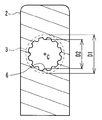
- FIG. 4 is a sectional view taken along line IV-IV in FIG. 3. It is a figure which shows the state which inserted the front-end
- upper refers to a position that is further away from the ground relative to the comparison target
- lower refers to a position that is closer to the ground relative to the comparison target.
- the height in the following description shall show the height relationship along the gravity direction.
- the endoscope reproduction processing tool 1 of the present embodiment is used together with an endoscope reprocessor 20 that is a device that performs a reproduction process on an endoscope.
- the regeneration treatment here is not particularly limited, and is a rinsing treatment with water, a washing treatment for removing dirt such as organic matter, a disinfection treatment for invalidating predetermined microorganisms, a sterilization treatment for eliminating or killing all microorganisms, Or any combination thereof may be used.
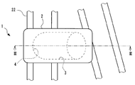
- FIG. 1 is a view of the inside of the processing tank 21 of the endoscope reprocessor 20 as viewed from above.
- the endoscope reprocessor 20 includes a processing tank 21 that houses the endoscope 30.
- the endoscope reprocessor 20 has a configuration in which at least one of a cleaning liquid, a disinfecting liquid, a sterilizing liquid, water, and air is introduced into the processing tank 21, and is an endoscope disposed in the processing tank 21. A reproduction process is performed on the mirror 30.
- the treatment tank 21 is open upward and is not shown in FIG. 1, but the opening of the treatment tank 21 is provided with a lid for opening and closing the opening.
- a holding net 22 is disposed on the bottom surface 21 a of the treatment tank 21.
- the holding net 22 holds the endoscope 30 in a predetermined posture in the processing tank 21.
- the holding net 22 holds the insertion portion 31 of the endoscope 30 in a wound state.
- the insertion portion 31 held by the holding net 22 is substantially along the substantially horizontal upper surface of the holding net 22.
- a connector 23 to which the connection tube 24 is connected is disposed in the treatment tank 21, a connector 23 to which the connection tube 24 is connected is disposed.
- the connector 23 is connected via a connection tube 24 to a channel 33 that is a conduit provided in the endoscope 30.
- the connector 23 delivers a fluid used for the regeneration process when the connection tube 24 is connected when the endoscope reprocessor 20 executes the regeneration process.
- the fluid delivered from the connector 23 is introduced into the channel 33 of the endoscope 30 via the connection tube 24.
- the channel 33 of the endoscope 30 communicates with a channel hole 32 a that is an opening provided at the distal end 32 of the insertion portion 31. Accordingly, at the time of executing the regeneration process by the endoscope reprocessor 20, at least a part of the fluid delivered from the connector 23 opens at the distal end 32 of the insertion portion 31 through the channel 33 of the endoscope 30. It is discharged from the channel hole 32a.
- opening such as a channel which penetrates a treatment tool, a channel which penetrates a miniature probe, or a channel which penetrates a raising base pull wire, is mentioned. Since the endoscope reprocessor 20 including the processing tank 21 and the endoscope 30 including the channel hole 32a at the distal end 32 of the insertion portion 31 are publicly known, detailed description of the configuration is omitted.
- the endoscope reproduction processing tool 1 is disposed in the processing tank 21 when the reproduction process by the endoscope reprocessor 20 is executed. 2, 3 and 4 show the configuration of the endoscope reproduction processing tool 1. FIG.
- the endoscope reproduction processing tool 1 includes a main body portion 2 and a fixing portion 5.
- the main body 2 includes a concave portion 3 into which the distal end 32 of the insertion portion 31 of the endoscope 30 is inserted, and a reflective surface 4 disposed on the bottom surface of the concave portion 3.
- FIG. 5 shows a state in which the distal end 32 of the insertion portion 31 of the endoscope 30 is inserted into the recess 3 in the same cross section as FIG.
- the shape of the recessed part 3 will not be specifically limited if it is a bottomed recessed shape which can insert the front-end
- the reflecting surface 4 is a surface configured by a part or all of the bottom surface of the recess 3.
- the concave portion 3 has a cylindrical surface having a linear central axis C as a side surface and a bottom surface having a spherical shape. That is, the reflective surface 4 of this embodiment is a spherical concave surface.
- the bottom surface of the recess 3 may be partly or entirely on a plane.
- the recess 3 may have a shape along a curved axis in the depth direction.
- the central axis C may be curved.
- one or a plurality of through holes penetrating the main body 2 may be opened on the side surface and the bottom surface of the recess 3.
- the fixing unit 5 fixes the main body unit 2 to the processing tank 21.
- the fixing portion 5 is an insertion portion when the angle formed between the reflecting surface 4 and the bottom surface 21a of the processing tank 21 is not less than 0 degrees and less than 90 degrees, and the distal end 32 of the insertion section 31 inserted into the recess 3 is inserted.
- the main body 2 is fixed to the treatment tank 21 so that the tip 32 of 31 is bent.
- the bending position of the tip 32 is not particularly limited, and can be appropriately determined depending on the height of the processing tank 21, the hardness of the insertion portion 31, the strength of the fluid derived from the channel, or the like.
- the angle formed by the reflecting surface 4 and the bottom surface 21a of the processing tank 21 is the tangent to the reflecting surface 4 on the vertical surface of the bottom surface 23a as shown in FIG.
- the angle A is defined by the tangent line orthogonal to the central axis and the bottom surface 21 a of the treatment tank 21.
- the angle A formed by the plane perpendicular to the central axis C in the vicinity of the reflective surface 4 and the bottom surface 21a of the treatment tank 21 is the reflective surface 4 and the treatment tank 21. This is the angle formed by the bottom surface 21a.
- the bottom surface 21a of the treatment tank 21 is a surface facing upward.
- the angle formed by the reflection surface 4 and the bottom surface 21a of the treatment tank 21 is 0 degree or more and less than 90 degrees. Opposite the bottom surface 21a.
- the central axis C of the recessed part 3 is linear, the opening of the recessed part 3 opposes the bottom face 21a.
- the fixing portion 5 of the present embodiment is provided integrally with the main body portion 2, and engages with the holding net 22 to fix the main body portion 2 to the processing tank 21 via the holding net 22.
- a surface in contact with the upper portion of the portion that supports the insertion portion 31 of the holding net 22 from below is referred to as a placement surface 22a.
- the mounting surface 22 a is a flat surface that is generally horizontal in the processing tank 21.
- the insertion portion 31 of the endoscope 30 supported by the holding net 22 is wound on the placement surface 22a.
- the entire concave portion 3 provided in the main body portion 2 is disposed above the placement surface 22a. That is, in a state where the fixing portion 5 is engaged with the holding net 22, the reflecting surface 4 faces the placement surface 22 a. Further, in a state where the fixing portion 5 is engaged with the holding net 22, the opening of the concave portion 3 faces the placement surface 22 a.
- the openings of the reflecting surface 4 and the recess 3 are directed downward from the horizontal.
- the opening of the reflecting surface 4 and the recess 3 faces downward from the horizontal, so that liquid can be prevented from remaining in the recess 3.
- the fixed portion 5 has an angle formed by the reflecting surface 4 and the placement surface 22a in the processing tank 21 of less than 90 degrees and 0 degrees or more, and the distal end 32 of the insertion portion 31 of the endoscope 30 in the recess 3. Is fixed to the processing tank 21 so that the main body 2 is inserted in a bent state.
- the fixing unit 5 can be attached to and detached from the holding net 22, and the main body unit 2 can be moved according to the position of the tip 32 of the insertion unit 31 in the processing tank 21.
- the endoscope reproduction processing tool 1 of the present embodiment includes an endoscope holding unit 6.
- the endoscope holding portion 6 is provided in the main body portion 2, and in a state where the distal end 32 of the insertion portion 31 of the endoscope 30 is inserted into the recessed portion 3, a channel hole 32 a that opens to the distal end 32. However, the distal end 32 of the insertion portion 31 is held so as to face the reflecting surface 4.
- the endoscope holding portion 6 of the present embodiment is provided at a position closer to the opening than the reflecting surface 4 in the recess 3, and protrudes from the side surface of the recess 3 toward the central axis C. Part.
- the endoscope holding portion 6 has a through hole having an inner diameter D2 that is smaller than the inner diameter D1 of the recess 3.
- the inner diameter D ⁇ b> 2 of the endoscope holding part 6 is larger than the outer diameter of the insertion part 31.
- the central axis of the through hole of the endoscope holding part 6 substantially coincides with the central axis of the recess 3.
- the endoscope holding part 6 is a part that narrows a part of the recess 3 at a position closer to the opening than the reflection surface 4 in the recess 3. Since the endoscope holding portion 6 is provided in the recess 3, the distal end 32 of the insertion portion 31 inserted into the recess 3 is separated from the side surface of the recess 3 and is located near the center of the recess 3. . That is, the endoscope holding portion 6 prevents the distal end 32 of the insertion portion 31 from coming into close contact with the side surface of the recess 3, and a space in which fluid can flow around the distal end 32 is generated.
- the inner surface of the endoscope holding part 6 is provided with unevenness.
- the unevenness provided on the inner surface of the endoscope holding portion 6 is for reducing the contact area between the endoscope holding portion 6 and the insertion portion 31.
- the shape of the unevenness provided on the inner surface of the endoscope holding portion 6 is not particularly limited, but in the present embodiment, as an example, the inner surface of the endoscope holding portion 6 is parallel to the central axis C of the recess 3. Are provided with a plurality of grooves. The groove is provided over the entire direction parallel to the central axis C of the inner surface of the endoscope holding portion 6.
- the concave and convex portions provided on the inner surface of the endoscope holding portion 6 are constituted by a plurality of grooves carved parallel to the central axis C of the concave portion 3, so that the inside of the endoscope holding portion 6 In the state in which the insertion portion 31 is inserted into the fluid, it is easy to discharge the fluid in the recess 3 through the space between the endoscope holding portion 6 and the insertion portion 31.
- the endoscope reprocessor 20 performs a reproduction process on the endoscope 30 using the endoscope reproduction processing tool 1 having the above-described configuration, as shown in FIG. 1 and FIG.
- the reproduction process is started after the distal end 32 of the insertion portion 31 of the endoscope 30 is inserted.
- a fluid is sent into the channel 33 of the endoscope 30, and at least a part of the fluid is a channel hole that opens at the distal end 32 of the insertion portion 31. It is discharged from 32a.
- the fluid discharged from the channel hole 32 a flows through the gap between the concave portion 3 and the insertion portion 31, and then flows out from the opening of the concave portion 3 to the processing tank 21.
- the fluid discharged from the channel hole 32 a changes its flow direction when it hits the reflecting surface 4 provided in the recess 3, and therefore, the fluid in the gap between the recess 3 and the insertion portion 31.
- the flow becomes turbulent.
- the vortex of the fluid discharged from the endoscope reprocessor 20 causes the insertion portion 31. It occurs around the tip 32 of the. Therefore, according to the endoscope regeneration processing tool 1 of the present embodiment, a turbulent flow of the fluid used for the regeneration process is generated around the distal end 32 of the insertion portion 31, and the regeneration process is focused on the distal end 32. Can be applied.
- the fluid flowing around the distal end 32 of the insertion portion 31 is a fluid after the fluid sent from the endoscope reprocessor 20 into the channel 33 is reflected by the reflecting surface 4. That is, in the present embodiment, the fluid that brings about the effect of subjecting the distal end 32 of the insertion portion 31 to the regenerative processing is sent from the configuration of the conventional endoscope reprocessor 20. Therefore, if the endoscope reproduction processing tool 1 of the present embodiment is used, the efficiency of the reproduction process for the distal end 32 of the insertion portion 31 can be improved without adding a new configuration to the endoscope reprocessor 20. .
- the endoscope regeneration processing tool 1 has been described as being fixed to the holding net 22.
- the endoscope regeneration processing tool 1 is directly fixed to the processing tank 21.
- the fixing unit 5 that directly fixes the endoscope reproduction processing tool 1 to the processing tank 21
- unevenness such as a connector provided in the processing tank 21 is gripped.
- the present invention is not limited to the above-described embodiments, and can be appropriately changed without departing from the gist or concept of the invention that can be read from the claims and the entire specification.
- the processing tool is also included in the technical scope of the present invention.
Landscapes
- Physics & Mathematics (AREA)
- Health & Medical Sciences (AREA)
- Life Sciences & Earth Sciences (AREA)
- Surgery (AREA)
- Optics & Photonics (AREA)
- Biomedical Technology (AREA)
- Medical Informatics (AREA)
- Nuclear Medicine, Radiotherapy & Molecular Imaging (AREA)
- Pathology (AREA)
- Radiology & Medical Imaging (AREA)
- Astronomy & Astrophysics (AREA)
- Biophysics (AREA)
- Engineering & Computer Science (AREA)
- Heart & Thoracic Surgery (AREA)
- General Physics & Mathematics (AREA)
- Molecular Biology (AREA)
- Animal Behavior & Ethology (AREA)
- General Health & Medical Sciences (AREA)
- Public Health (AREA)
- Veterinary Medicine (AREA)
- Endoscopes (AREA)
Abstract
内視鏡再生処理具は、内視鏡の挿入部の先端を挿入する凹部、および、前記凹部の底面に配置され前記先端で開口しているチャンネル孔から吐出された流体を反射する反射面を有する本体部と、内視鏡リプロセッサの処理槽の底面と前記反射面との成す角度が0度以上90度未満となり、前記凹部内に前記挿入部の前記先端が屈曲した状態で挿入されるように前記本体部を前記処理槽に固定する固定部と、を含む。
Description
本発明は、内視鏡の再生処理に使用する内視鏡再生処理具に関する。
医療分野において使用される内視鏡は、使用後に消毒液等の薬液を用いた再生処理が施される。また、内視鏡に対して処理槽内において再生処理を自動的に行う内視鏡リプロセッサが知られている。内視鏡リプロセッサは、内視鏡が備える管路であるチャンネル内に薬液、水、空気等の再生処理に用いる流体を送り込む構成を有している。
また、内視鏡の挿入部の先端は、レンズやチャンネルの開口等の凹凸形状を有している。挿入部の先端に設けられた凹凸形状には異物が付着しやすいことから、挿入部の先端に対する再生処理は重点的に行われることが好ましい。
例えば日本国特開2012-101016号公報には、パイプ内に内視鏡挿入部を挿入し、パイプ内に水を流すことにより内視鏡挿入部を流水洗浄する際に、内視鏡先端レンズ面近傍で乱流を起こすことにより、内視鏡先端レンズ面の洗浄の効果を向上させる技術が開示されている。
日本国特開2012-101016号公報されている技術では、内視鏡先端レンズ面近傍で乱流の流速を上げると、洗浄の効果が向上するものの、パイプ内から内視鏡挿入部が抜け出そうとする力も強くなってしまう。
本発明は、上述した問題点を解決するものであって、内視鏡リプロセッサによる再生処理の実行時において、内視鏡の挿入部の先端に対して重点的に再生処理を施すことができる内視鏡再生処理具を提供することを目的とする。
本発明の一態様による内視鏡再生処理具は、内視鏡の挿入部の先端を挿入する凹部、および、前記凹部の底面に配置され前記先端で開口しているチャンネル孔から吐出された流体を反射する反射面を有する本体部と、内視鏡リプロセッサの処理槽の底面と前記反射面との成す角度が0度以上90度未満となり、前記凹部内に前記挿入部の前記先端が屈曲した状態で挿入されるように前記本体部を前記処理槽に固定する固定部と、を含む。
以下に、本発明の好ましい形態について図面を参照して説明する。なお、以下の説明に用いる各図においては、各構成要素を図面上で認識可能な程度の大きさとするため、構成要素毎に縮尺を異ならせてあるものであり、本発明は、これらの図に記載された構成要素の数量、構成要素の形状、構成要素の大きさの比率、および各構成要素の相対的な位置関係のみに限定されるものではない。
なお、以下の説明において、上方とは比較対象に対してより地面から遠ざかった位置のことを指し、下方とは比較対象に対してより地面に近づいた位置のことを指す。また、以下の説明における高低とは、重力方向に沿った高さ関係を示すものとする。
本実施形態の内視鏡再生処理具1は、内視鏡に対して再生処理を施す装置である内視鏡リプロセッサ20と共に用いられる。ここでいう再生処理とは特に限定されるものではなく、水によるすすぎ処理、有機物等の汚れを落とす洗浄処理、所定の微生物を無効化する消毒処理、全ての微生物を排除もしくは死滅させる滅菌処理、またはこれらの組み合わせ、のいずれであってもよい。
図1は、内視鏡リプロセッサ20の処理槽21内を上方から見た図である。内視鏡リプロセッサ20は、内視鏡30を収容する処理槽21を備えている。内視鏡リプロセッサ20は、処理槽21内に洗浄液、消毒液、滅菌液、水および空気のうちの少なくとも1種の流体を導入する構成を有し、処理槽21内に配置された内視鏡30に対して再生処理を施す。
処理槽21は、上方に向かって開口しており、図1には示していないが、処理槽21の開口には、当該開口を開閉する蓋が設けられている。
処理槽21の底面21a上には、保持網22が配置されている。保持網22は、処理槽21内において内視鏡30を所定の姿勢で保持する。本実施形態では、保持網22は、内視鏡30の挿入部31を、巻回した状態で保持する。保持網22によって保持された状態の挿入部31は、保持網22の略水平な上面に概ね沿った状態となる。
また、処理槽21内には、接続チューブ24が接続されるコネクタ23が配設されている。コネクタ23は、接続チューブ24を介して内視鏡30が備える管路であるチャンネル33に接続される。コネクタ23は、内視鏡リプロセッサ20による再生処理の実行時において、接続チューブ24が接続されている場合に、再生処理に用いられる流体を送出する。コネクタ23から送出された流体は、接続チューブ24を経由して内視鏡30のチャンネル33内に導入される。
内視鏡30のチャンネル33は、挿入部31の先端32に設けられた開口であるチャンネル孔32aに連通している。したがって、内視鏡リプロセッサ20による再生処理の実行時において、コネクタ23から送出された流体の少なくとも一部は、内視鏡30のチャンネル33を通って挿入部31の先端32において開口しているチャンネル孔32aから吐出される。ここでいうチャンネル孔32aとしては、特に限定されないが、例えば、処置具を挿通するチャンネル、ミニチュアプローブを挿通するチャンネル、または起上台牽引ワイヤを挿通するチャンネルなどの開口が挙げられる。処理槽21を備える内視鏡リプロセッサ20および挿入部31の先端32にチャンネル孔32aを備える内視鏡30は公知のものであるため、構成の詳細な説明は省略する。
内視鏡再生処理具1は、内視鏡リプロセッサ20による再生処理の実行時に、処理槽21内に配置される。図2、図3および図4に、内視鏡再生処理具1の構成を示す。
内視鏡再生処理具1は、本体部2および固定部5を備える。本体部2は、内視鏡30の挿入部31の先端32を挿入する凹部3と、凹部3の底面に配置された反射面4と、を有する。
図5は、図3と同一の断面において、凹部3内に内視鏡30の挿入部31の先端32を挿入した状態を示している。凹部3の形状は、挿入部31の先端32を挿入可能な有底の凹形状であれば特に限定されるものではない。反射面4は、凹部3の底面の一部または全部の領域により構成されている面である。
本実施形態では一例として、凹部3は、直線状の中心軸Cを有する円柱面を側面とし、底面が球面状である。すなわち、本実施形態の反射面4は球形の凹面である。なお、凹部3の底面は一部または全部が平面上であってもよい。また、凹部3は、深さ方向に曲線状の軸に沿った形状であってもよい。例えば、中心軸Cは曲線状であってもよい。また、凹部3の側面および底面には、本体部2を貫通する1つ又は複数の貫通孔が開口していてもよい。
固定部5は、本体部2を処理槽21に固定する。固定部5は、反射面4と処理槽21の底面21aとの成す角度が0度以上90度未満となり、かつ凹部3内に挿入された挿入部31の先端32が挿入された場合において挿入部31の先端32が屈曲した状態となるように、本体部2を処理槽21に固定する。先端32の屈曲位置は特に限定されず、処理槽21の高さ、挿入部31の硬さ、またはチャンネルから導出される流体の強さ等により適宜決定することができる。
反射面4が曲面である本実施形態では、反射面4と処理槽21の底面21aとが成す角度とは、図3に示すように、底面23aの垂直面上において、反射面4の接線のうち前記中心軸に対して直交する接線と、処理槽21の底面21aとが成す角度Aである。なお、例えば中心軸Cが曲線状である場合には、反射面4の近傍において中心軸Cに直交する平面と、処理槽21の底面21aとが成す角度Aが、反射面4と処理槽21の底面21aとが成す角度である。
処理槽21の底面21aは、上方を向く面である。固定部5によって本体部2が処理槽21に固定されている状態においては、反射面4と処理槽21の底面21aとの成す角度が0度以上90度未満であることから、反射面4は底面21aと対向する。また、本実施形態では、凹部3の中心軸Cが直線状であることから、凹部3の開口は底面21aと対向する。
具体的には、本実施形態の固定部5は、本体部2と一体に設けられており、保持網22と係合することにより、保持網22を介して本体部2を処理槽21に固定する。ここで、保持網22の挿入部31を下方から支持する部位の上方に接する面を載置面22aとする。載置面22aは、処理槽21内において概ね水平となる平面である。保持網22によって支持されている内視鏡30の挿入部31は、載置面22a上において巻回された状態となる。
固定部5が保持網22に係合している状態において、本体部2に設けられた凹部3の全体が、載置面22aよりも上方に配置される。すなわち、固定部5が保持網22に係合している状態において、反射面4は載置面22aと対向する。また、固定部5が保持網22に係合している状態において、凹部3の開口は載置面22aと対向する。
したがって本実施形態では、固定部5が保持網22に係合している状態において、反射面4および凹部3の開口が水平よりも下方に向く。反射面4および凹部3の開口が水平よりも下方を向くことにより、凹部3内への液体の残留を防止できる。
そして、固定部5によって以上に説明した姿勢で処理槽21に固定されている凹部3内に、挿入部31の先端32を挿入した場合、図5に示すように、挿入部31の先端32は、載置面22aから上方に離間する。すなわち、凹部3内に先端32が挿入された挿入部31は、先端32の近傍が載置面22aから立ち上がるように屈曲する。
このように、固定部5は、反射面4と処理槽21内の載置面22aとの成す角度が90度未満0度以上となり、凹部3内に内視鏡30の挿入部31の先端32が屈曲した状態で挿入されるように、本体部2を処理槽21に固定する。固定部5は、保持網22に対して着脱可能であり、処理槽21内における挿入部31の先端32の位置に応じて本体部2を移動させることができる。
また、本実施形態の内視鏡再生処理具1は、内視鏡保持部6を備える。内視鏡保持部6は、本体部2に設けられており、凹部3内に内視鏡30の挿入部31の先端32が挿入されている状態において、先端32に開口しているチャンネル孔32aが、反射面4と対向するように挿入部31の先端32を保持する。
具体的には、本実施形態の内視鏡保持部6は、凹部3内の反射面4よりも開口に近い位置に設けられており、凹部3の側面から中心軸Cに向かって突出する凸部である。図4に示すように、内視鏡保持部6は、凹部3の内径D1よりも小さい内径D2の貫通孔を有している。内視鏡保持部6の内径D2は、挿入部31の外径よりも大きい。内視鏡保持部6の貫通孔の中心軸は、凹部3の中心軸と略一致する。
言い換えれば、内視鏡保持部6は、凹部3内の反射面4よりも開口に近い位置において、凹部3の一部を狭窄する部位である。凹部3に内視鏡保持部6が設けられていることにより、凹部3内に挿入された状態の挿入部31の先端32は、凹部3の側面から離間し、凹部3の中央付近に位置する。すなわち、内視鏡保持部6によって、挿入部31の先端32が凹部3の側面に密着することが防止され、先端32の周囲に流体が流れることが可能な空間が生じる。
また、内視鏡保持部6の内面には、凹凸が設けられている。内視鏡保持部6の内面に設けられた凹凸は、内視鏡保持部6と挿入部31との接触面積を小さくするためのものである。内視鏡保持部6の内面に凹凸が設けられていることにより、処理槽21内に液体を貯留した場合において、当該液体が内視鏡保持部6と挿入部31との間に流れ込みやすくなるため、挿入部31の表面全体を液体と接触させることができる。
内視鏡保持部6の内面に設けられる凹凸の形状は特に限定されるものではないが、本実施形態では一例として、内視鏡保持部6の内面には、凹部3の中心軸Cと平行に設けられた複数の溝が設けられている。当該溝は、内視鏡保持部6の内面の中心軸Cに平行な方向の全体にわたって設けられている。本実施形態のように、内視鏡保持部6の内面に設けられる凹凸を、凹部3の中心軸Cと平行に彫設された複数の溝によって構成することにより、内視鏡保持部6内に挿入部31が挿入されている状態において、凹部3内の流体を内視鏡保持部6と挿入部31との間を通して排出することが容易となる。
以上に説明した構成を有する内視鏡再生処理具1を用いて内視鏡リプロセッサ20により内視鏡30に対する再生処理を実行する場合には、図1および図5に示すように、凹部3内に内視鏡30の挿入部31の先端32が挿入された状態とした後に再生処理を開始する。
内視鏡リプロセッサ20による再生処理の実行時には、前述のように、内視鏡30のチャンネル33内に流体が送り込まれ、当該流体の少なくとも一部は挿入部31の先端32に開口するチャンネル孔32aから吐出される。チャンネル孔32aから吐出された流体は、凹部3と挿入部31との間の隙間を流れた後に、凹部3の開口から処理槽21へ流出する。
ここで、チャンネル孔32aから吐出された流体は、凹部3内に設けられた反射面4に当たることにより流れの向きが変化することから、凹部3と挿入部31との間の隙間において当該流体の流れは乱れた状態となる。
このように、内視鏡再生処理具1を用いて内視鏡リプロセッサ20により内視鏡30に対する再生処理を実行すれば、内視鏡リプロセッサ20から吐出される流体の渦が挿入部31の先端32の周囲に発生する。よって、本実施形態の内視鏡再生処理具1によれば、挿入部31の先端32の周囲に再生処理に用いられる流体の乱流を発生させ、先端32に対して重点的に再生処理を施すことができる。
また本実施形態において、挿入部31の先端32の周囲を流れる流体は、内視鏡リプロセッサ20からチャンネル33内に送り込まれた流体が、反射面4によって反射された後のものである。すなわち、本実施形態において、挿入部31の先端32に対して重点的に再生処理を施す効果をもたらす流体は、従来の内視鏡リプロセッサ20が備える構成から送出されたものである。したがって、本実施形態の内視鏡再生処理具1を用いれば、内視鏡リプロセッサ20に新たな構成を付加することなく、挿入部31の先端32に対する再生処理の効率を向上させることができる。
また、凹部3内において、挿入部31の先端32に開口するチャンネル孔32aから流体が吐出される場合には、挿入部31の先端32を凹部3内から抜け出す方向に推進する力が発生する。ここで、本実施形態の内視鏡再生処理具1の凹部3内に挿入された挿入部31の先端32は、載置面22aから立ち上がるように屈曲している。このため、本実施形態では、挿入部31の先端32が、凹部3内から抜け出す方向への移動が、載置面22aによって規制される。
すなわち本実施形態では、チャンネル孔32aから流体を吐出する際に、凹部3から抜け出す方向に先端32を移動させるように先端32に加わる力の一部は、載置面22aに伝わる。したがって、本実施形態によれば、チャンネル孔32aから吐出される流体の速度を高めたとしても、凹部3内から挿入部31の先端32が抜け出してしまうことがない。このように、本実施形態では、凹部3内からの挿入部31の先端32の抜け出しを防止するための挿入部31の把持する機構が不要であることから、当該把持する機構によって挿入部31の表面全体への流体の接触が妨げられることがない。
なお、以上に説明した実施形態では、内視鏡再生処理具1は、保持網22に固定されるものとして説明したが、内視鏡再生処理具1は、処理槽21に直接的に固定される構成を有していてもよい。内視鏡再生処理具1を処理槽21に直接的に固定する固定部5の変形例としては、例えば吸盤や磁石によって、処理槽21の壁面に吸着する構成が挙げられる。また例えば、固定部5の変形例としては、処理槽21内に設けられたコネクタ等の凹凸を把持する構成が挙げられる。
本発明は、前述した実施形態に限られるものではなく、請求の範囲および明細書全体から読み取れる発明の要旨或いは思想に反しない範囲で適宜変更可能であり、そのような変更を伴う内視鏡再生処理具もまた本発明の技術的範囲に含まれるものである。
本出願は、2017年3月15日に日本国に出願された特願2017-50068号を優先権主張の基礎として出願するものであり、上記の開示内容は、本願明細書、請求の範囲、図面に引用されたものとする。
Claims (3)
- 内視鏡の挿入部の先端を挿入する凹部、および、前記凹部の底面に配置され前記先端で開口しているチャンネル孔から吐出された流体を反射する反射面を有する本体部と、
内視鏡リプロセッサの処理槽の底面と前記反射面との成す角度が0度以上90度未満となり、前記凹部内に前記挿入部の前記先端が屈曲した状態で挿入されるように前記本体部を前記処理槽に固定する固定部と、
を含むことを特徴とする内視鏡再生処理具。 - 前記本体部に設けられ、前記チャンネル孔が前記反射面と対向するように前記挿入部を保持する内視鏡保持部、
を含むことを特徴とする請求項1に記載の内視鏡再生処理具。 - 前記固定部は、保持網を介して前記本体部を前記処理槽に固定することを特徴とする請求項1に記載の内視鏡再生処理具。
Applications Claiming Priority (2)
| Application Number | Priority Date | Filing Date | Title |
|---|---|---|---|
| JP2017050068 | 2017-03-15 | ||
| JP2017-050068 | 2017-03-15 |
Publications (1)
| Publication Number | Publication Date |
|---|---|
| WO2018168010A1 true WO2018168010A1 (ja) | 2018-09-20 |
Family
ID=63523183
Family Applications (1)
| Application Number | Title | Priority Date | Filing Date |
|---|---|---|---|
| PCT/JP2017/031761 Ceased WO2018168010A1 (ja) | 2017-03-15 | 2017-09-04 | 内視鏡再生処理具 |
Country Status (1)
| Country | Link |
|---|---|
| WO (1) | WO2018168010A1 (ja) |
Citations (3)
| Publication number | Priority date | Publication date | Assignee | Title |
|---|---|---|---|---|
| JPH03280925A (ja) * | 1990-03-30 | 1991-12-11 | Olympus Optical Co Ltd | 内視鏡洗浄装置 |
| JP2012101016A (ja) * | 2010-11-08 | 2012-05-31 | Takashi Itabashi | 椀状流水反射板を取り入れた改良型鼻咽喉軟性内視鏡洗浄器 |
| JP2015054212A (ja) * | 2013-09-13 | 2015-03-23 | オリンパスメディカルシステムズ株式会社 | 内視鏡洗浄消毒具、内視鏡洗浄消毒装置 |
-
2017
- 2017-09-04 WO PCT/JP2017/031761 patent/WO2018168010A1/ja not_active Ceased
Patent Citations (3)
| Publication number | Priority date | Publication date | Assignee | Title |
|---|---|---|---|---|
| JPH03280925A (ja) * | 1990-03-30 | 1991-12-11 | Olympus Optical Co Ltd | 内視鏡洗浄装置 |
| JP2012101016A (ja) * | 2010-11-08 | 2012-05-31 | Takashi Itabashi | 椀状流水反射板を取り入れた改良型鼻咽喉軟性内視鏡洗浄器 |
| JP2015054212A (ja) * | 2013-09-13 | 2015-03-23 | オリンパスメディカルシステムズ株式会社 | 内視鏡洗浄消毒具、内視鏡洗浄消毒装置 |
Similar Documents
| Publication | Publication Date | Title |
|---|---|---|
| EP1815782A2 (en) | Apparatus and method for dewatering endoscope channels | |
| JP6389244B2 (ja) | 医療用付属品ホルダ | |
| JP5927362B1 (ja) | 内視鏡接続具及び内視鏡リプロセッサ | |
| JP6013671B2 (ja) | 挿入機器の洗浄具 | |
| CN108471936B (zh) | 内窥镜再生处理器具 | |
| JP2018517442A (ja) | 内視鏡、内視鏡用キャップ及び内視鏡用キャップ形成方法 | |
| JP2008272285A (ja) | 超音波プローブ用洗浄具 | |
| JP2025516557A (ja) | 乾燥及び/又は清掃デバイスのためのシステム及び方法 | |
| JP2021527458A (ja) | 内視鏡再処理装置 | |
| JP2003111725A (ja) | 内視鏡洗滌消毒装置 | |
| WO2018168010A1 (ja) | 内視鏡再生処理具 | |
| CN115137863A (zh) | 用于悬挂无线超声换能器的超声探头吊架和方法 | |
| US6581615B2 (en) | Apparatus for washing and disinfecting an endoscope cable assembly | |
| JPH08266595A (ja) | 管用殺菌装置及び洗浄殺菌装置 | |
| JP3947730B2 (ja) | 内視鏡洗滌消毒装置 | |
| JP6798147B2 (ja) | 除菌装置及び温水装置 | |
| US20190151485A1 (en) | Disinfecting and sterilizing device for medical sensor | |
| JP6013658B2 (ja) | 洗浄システム及び洗浄方法 | |
| WO2017033485A1 (ja) | 内視鏡リプロセッサ | |
| JP5969899B2 (ja) | 内視鏡洗浄装置 | |
| CN108463158A (zh) | 内窥镜再生处理器具 | |
| JP2009225811A (ja) | 内視鏡洗浄消毒装置 | |
| CN112402658A (zh) | 一种耳鼻喉科用器具消毒装置 | |
| JP6957770B2 (ja) | 内視鏡アタッチメントおよび内視鏡システム | |
| JP2009225812A (ja) | 内視鏡洗浄消毒装置 |
Legal Events
| Date | Code | Title | Description |
|---|---|---|---|
| 121 | Ep: the epo has been informed by wipo that ep was designated in this application |
Ref document number: 17901218 Country of ref document: EP Kind code of ref document: A1 |
|
| NENP | Non-entry into the national phase |
Ref country code: DE |
|
| 122 | Ep: pct application non-entry in european phase |
Ref document number: 17901218 Country of ref document: EP Kind code of ref document: A1 |
|
| NENP | Non-entry into the national phase |
Ref country code: JP |