WO2018164077A1 - 排土板の位置補正量取得方法 - Google Patents
排土板の位置補正量取得方法 Download PDFInfo
- Publication number
- WO2018164077A1 WO2018164077A1 PCT/JP2018/008412 JP2018008412W WO2018164077A1 WO 2018164077 A1 WO2018164077 A1 WO 2018164077A1 JP 2018008412 W JP2018008412 W JP 2018008412W WO 2018164077 A1 WO2018164077 A1 WO 2018164077A1
- Authority
- WO
- WIPO (PCT)
- Prior art keywords
- correction amount
- position correction
- earth
- measurement
- construction work
- Prior art date
- Legal status (The legal status is an assumption and is not a legal conclusion. Google has not performed a legal analysis and makes no representation as to the accuracy of the status listed.)
- Ceased
Links
Images




Classifications
-
- E—FIXED CONSTRUCTIONS
- E02—HYDRAULIC ENGINEERING; FOUNDATIONS; SOIL SHIFTING
- E02F—DREDGING; SOIL-SHIFTING
- E02F3/00—Dredgers; Soil-shifting machines
- E02F3/04—Dredgers; Soil-shifting machines mechanically-driven
- E02F3/76—Graders, bulldozers, or the like with scraper plates or ploughshare-like elements; Levelling scarifying devices
- E02F3/80—Component parts
- E02F3/84—Drives or control devices therefor, e.g. hydraulic drive systems
-
- G—PHYSICS
- G01—MEASURING; TESTING
- G01B—MEASURING LENGTH, THICKNESS OR SIMILAR LINEAR DIMENSIONS; MEASURING ANGLES; MEASURING AREAS; MEASURING IRREGULARITIES OF SURFACES OR CONTOURS
- G01B11/00—Measuring arrangements characterised by the use of optical techniques
-
- G—PHYSICS
- G01—MEASURING; TESTING
- G01C—MEASURING DISTANCES, LEVELS OR BEARINGS; SURVEYING; NAVIGATION; GYROSCOPIC INSTRUMENTS; PHOTOGRAMMETRY OR VIDEOGRAMMETRY
- G01C15/00—Surveying instruments or accessories not provided for in groups G01C1/00 - G01C13/00
Definitions
- the present invention relates to a method for obtaining a position correction amount from a position measuring device to a soil discharging board in a construction work machine.
- bulldozers are used as construction work machines when leveling and paving, and the operation of this bulldozer, that is, the movement of the bulldozer and the operation of the earthing board (blade) are specified in advance and automatically.
- Control is performed to perform or assist the operation of the bulldozer by the operator. In order to perform such control, it is necessary to accurately grasp the position of the cutting edge of the earth discharging plate.
- FIGS. 7A and 7B are schematic views showing a conventional method for obtaining the position correction amount of the earth discharging board, where FIG. 7A is a side view and FIG. 7B is a front view.
- a mast 150 is placed at the center of the upper edge of the earth discharging plate 120, and the upper end of the mast
- a position measuring device 140 composed of a GPS device is disposed in
- the inclination measuring apparatus 160 is arrange
- Patent Document 1 describes a bulldozer in which position acquisition means is installed on a mast arranged on a soil discharging board.
- the position acquisition device is arranged, and it is necessary to perform maintenance to prevent the mast from being broken, and there is a concern that the mast hinders the operator's view.
- arranging the position measuring device on the ceiling of the vehicle body has been studied. In this case, setting of the position correction amount from the position measuring device to the cutting edge of the earth discharging plate is complicated, and furthermore, since the vehicle body and the earth discharging plate are not interlocked, an inclination measuring device is required for each.
- the position measuring device When the position measuring device is arranged in an existing bulldozer and the position correction amount is set, information on the dimensions of each member based on the design drawing or the like can be used. However, some existing bulldozers do not have this information, and in this case, it is necessary to accurately measure the dimensions of the vehicle body and the link that supports the earth discharge plate from the vehicle body. When measuring this dimension, it may not be possible to measure accurately with a tape measure or the like because the measurement location is covered with a cover.
- the present invention has been made in view of the above-described problems, and a soil removal board that can easily and accurately acquire a position correction amount between a position measuring device disposed on a vehicle body of a construction machine and a blade edge of the soil removal board. It is an object of the present invention to provide a position correction amount acquisition method.
- the invention according to claim 1, which solves the above problem, provides a position correction amount between a cutting edge position of the earth removal plate disposed on the vehicle body of the construction work machine via a connection portion and a position acquisition device disposed on the vehicle body.
- a method for obtaining wherein a position of the position obtaining device and a position of each part of the construction work machine are measured by a surveying device arranged on a side of the construction work machine, and the position obtaining device is obtained from these measured values.
- a position correction amount acquisition method for a soil removal board comprising calculating a position correction amount from the cutting edge to the cutting edge position of the soil removal board.
- the invention according to claim 2 is the method for acquiring the position correction amount of the earth discharging board according to claim 1, wherein the surveying device has a position of the position acquisition device from both sides sandwiching a central axis of the construction work machine, The position of each part of the construction work machine is measured.
- the invention according to claim 3 is characterized in that, in the method for acquiring the position correction amount of the earth discharging board according to claim 2, two fixed points spaced apart from the construction work machine are measured.
- the invention according to claim 4 is the method for obtaining the position correction amount of the earth discharging board according to claim 1, wherein the surveying device includes its own position, the azimuth angle of the measurement location, the depression angle or elevation angle of the measurement location, And a total station that measures the distance to the measurement location and digitally outputs it.
- the invention according to claim 5 is the method for acquiring the position correction amount of the earth discharge plate according to claim 1, wherein each measurement result is input to a computer, and the computer obtains a cutting edge of the earth discharge plate from the position acquisition device. The position correction amount up to the position is calculated.
- the invention according to claim 6 is the method for obtaining the position correction amount of the earth discharging board according to claim 1, wherein the inclination of the construction work machine at the time of measurement is measured from the measurement result of the surveying device, and the inclination correction is performed. It is characterized by performing.
- the invention according to claim 7 is characterized in that in the method for acquiring the position correction amount of the earth discharging board according to claim 1, the measurement is performed from a plurality of different places by one surveying device.
- the position correction amount of the earth discharge plate is easily and accurately set to the edge position of the earth discharge plate. As a result, the leveling accuracy due to the operation of the construction machine due to the measurement error is not lowered.
- the position of the position acquisition device measured by the surveying device arranged on the side of the construction work machine the position of each part of the construction work machine, To calculate the position correction amount from the position acquisition device to the cutting edge position of the earth discharging plate. Therefore, it is possible to measure a portion that cannot be directly measured, to prevent the occurrence of errors due to accumulation of measurement errors, and to easily and accurately obtain the position correction amount up to the cutting edge position of the earth discharging plate.
- the surveying device determines the position of the position acquisition device from both sides sandwiching the central axis of the construction work machine and the position of each part of the construction work machine. taking measurement. Therefore, measurement from both sides of the construction machine can be performed, and an accurate position correction amount can be acquired.
- the two fixed points separated from the construction work machine are measured by the surveying device. Therefore, the positions of the two surveying devices can be determined, and the positions of the position measuring device and each part of the construction machine can be measured with respect to the horizontal plane.
- the surveying device is a total station, the azimuth angle of the measurement location, the depression angle or elevation angle surrounding price of the measurement location, and the distance to the measurement location Measure and output digitally. Therefore, the position of each part of the position measuring device and the construction work machine is accurately and quickly measured and digitally output.
- each measurement result is input to the computer, and the position correction amount from the position acquisition device to the blade edge position of the earth discharging plate is calculated by the computer. Calculate. Therefore, the calculation can be performed automatically and accurately.
- the inclination of the construction work machine at the time of measurement is measured from the measurement result of the surveying device, and the inclination correction is performed. Therefore, it is possible to detect the inclination state of the construction machine and obtain the position correction amount in a state where there is no inclination.
- the position correction amount acquisition method of the earth removal board of Claim 7 it measures from several different places with the said one surveying apparatus. Therefore, the position correction amount including the inclination correction of the construction machine can be measured with one surveying device.
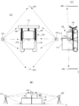
- FIG. 1 is a schematic diagram illustrating a method for obtaining a position correction amount of a soil discharge board according to an embodiment of the present invention, where (a) is a side view, (b) is a front view, and FIG. 2 is according to an embodiment of the present invention.
- FIG. 3 shows an implementation state of the method for obtaining the position correction amount of the earth discharging board, (a) is a plan view, (b) is a front view, (c) is a side view, and FIG. 3 is the position correction amount of the earth discharging board.
- Fig. 4 is a schematic diagram showing the flow of processing in the acquisition method
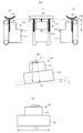
- Fig. 4 is a schematic diagram showing the dimensions of each part that can be acquired by the position correction amount acquisition method of the soil discharge board
- (B) and (c) are front views.
- the position correction amount C between the position and the position acquisition device 210 arranged on the vehicle body 110 is acquired.
- the position acquisition device 210 is configured by a GNSS (Global Navigation Satellite System) device.
- the position of the position acquisition device 210 is based on the position of the GNSS antenna.
- two surveying devices 220 and 220 are disposed on both sides of the central axis of the bulldozer 100 disposed on the plane G, and are disposed on the vehicle body 110 by the surveying devices 220 and 220.
- the position of the position acquisition device 210, the position of each part of the bulldozer, and the positions of the two fixed points 230, 230 installed away from the bulldozer 100 are measured.
- the reason for measuring from both sides is to measure the inclination when there is an inclination in the plane G where the bulldozer 100 is installed. Further, by measuring the fixed points 230 and 230, the height difference between the two surveying devices 220 and 220 can be grasped.
- these measured values are input to the computer 250, and the position correction amount C from the position acquisition device 210 to the cutting edge 121 position of the earth discharging plate 120 is calculated by software.
- the measurement can be performed from the other side. In this case, measurement can be performed with one surveying device.
- Spreadsheet software can be used as the software.
- the surveying device 220 used in the present embodiment is a total station, and measures the azimuth angle of the measurement location, the depression angle or elevation angle surrounding price of the measurement location, and the distance to the measurement location, and outputs them digitally.
- the surveying device 220 can perform measurement in a prism mode that receives and measures reflected light from a mirror or a prism, and a non-prism mode that receives and measures reflected light from a measurement object.
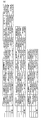
- FIG. 5 shows an example of the measurement in the method for acquiring the position correction amount of the earth discharging board according to the embodiment.
- (A), (i), (ii), and (iii) are photographs showing the measurement position, and (b) is the measurement. It is a figure which shows the table
- the surveying device 220 when it is visible from the surveying device 220 and can be measured directly, it is measured in the non-prism mode of the surveying device 220, and when the measurement location is not visible, an auxiliary tool with a reflection mirror or the like placed at the tip is used. And measure in prism mode.
- a measurement aid When using a measurement aid, subtract the dimensions of the aid after measurement from the height position.
- Measured locations can be the following 21 locations, for example.
- the bulldozer 100 includes two front and rear position acquisition devices.
- the position of the front position acquisition device (the front GNSS antenna center) is used.
- this measurement location can be changed as needed.
- the operator inputs these measured values into the software of the computer 250.
- the input state is shown in FIG.
- the position of each part is input as three-dimensional information (X, Y, H).
- surface is a height dimension of an auxiliary tool.
- the width “w” of the earth discharging plate 120 is further compared with the actual measurement value obtained by measuring the measurement value of the surveying device 220 with the actual measurement value of the tape measure, or the actual measurement value of the bulldozer 100 measured by the inclinometer. It can be an accurate value.
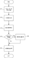
- FIG. 6 is a flowchart showing the processing of the method for acquiring the position correction amount of the earth discharging board.
- the bulldozer 100 is arranged on the plane G (step ST1). It is desirable that the bulldozer is placed at a horizontal position. However, even if the plane G is slightly inclined, it can be corrected by a later process.
- the position is measured (step ST2). Accordingly, the length dimension “L” of the connecting portion 130 shown in FIG. 6A and the height dimension “h1” from the plane of the position acquisition device 210 shown in FIG. 6B are shown in FIG.
- the width dimension “W” and the like of the earth removing plate 120 can be acquired.
- the computer 250 calculates the inclination of the plane on which the bulldozer 100 is arranged (step ST3), and confirms whether inclination correction is necessary (step ST4).
- the inclination is measured under the right rear wheel crawler (FIG. 5 (a) (i) “b”), under the right front wheel crawler (“d”), and under the left rear wheel crawler (FIG. 5 (a) (ii) “ q "), and the position under the left front wheel crawler belt (" t ").
- step ST6 when the plane G on which the bulldozer 100 is arranged has an inclination “ ⁇ ” and inclination correction is necessary (Yes in step ST6), the computer 250 calculates an inclination correction amount (step ST5). Then, the height dimension “h0” of the position acquisition device 210 that corrects the inclination correction amount is calculated (step ST6). A position correction amount C is calculated based on the height dimension “h0” corrected for the inclination and the center of the previous GNSS antenna (FIGS. 5A, 5I, and “H”) (step ST6). If tilt correction is not necessary (No in step ST4), the position correction amount C is calculated as it is (step ST6).
- the position correction amount C for the position acquiring device 210 of the earth discharging plate 120 can be easily and accurately obtained.
- Accurate control can be performed by using the position correction amount C for automatic operation control of the bulldozer 100 and driving assistance.
- the present invention can be similarly implemented by using a position measurement system using a total station, a prism, and the like instead of using the GNSS device mounted on the bulldozer 100 as described in the above embodiment. .
Landscapes
- Engineering & Computer Science (AREA)
- Physics & Mathematics (AREA)
- General Physics & Mathematics (AREA)
- Radar, Positioning & Navigation (AREA)
- Remote Sensing (AREA)
- Mechanical Engineering (AREA)
- Mining & Mineral Resources (AREA)
- Civil Engineering (AREA)
- General Engineering & Computer Science (AREA)
- Structural Engineering (AREA)
- Operation Control Of Excavators (AREA)
Abstract
【課題】建設作業機械の車体に配置した位置測定装置と排土板の刃先との位置補正量を簡単かつ正確に取得する。 【解決手段】ブルドーザー100の車体110に接続部130を介して配置された排土板120の刃先121の位置と、車体110に配置された位置取得装置210との位置補正量Cを取得する方法である。ブルドーザー100の側方の両側に配置した測量装置220で位置取得装置210の位置と、ブルドーザー100の各部の位置とを測定し(ステップST2)、これらの測定値から位置取得装置210から排土板120の刃先121の位置までの位置補正量Cを演算する(ステップST3~ST6)。
Description
本発明は、建設作業機械において、位置測定装置から排土板までの位置補正量を取得する方法に関する。
従来、土木、建設分野では、整地、舗装を行うに際し、建設作業機械としてブルドーザーが使用され、このブルドーザーの操作、即ちブルドーザーの移動や排土板(ブレード)の操作を予め指定して自動的に行ったり、オペレータによるブルドーザーの操作を補助したりする制御が行われている。このような制御を行うためには、排土板の刃先の位置を正確に把握しておく必要がある。
従来、ブルドーザーの排土板の刃先の位置を把握するため、以下の方法が採用されている。図7は従来の排土板の位置補正量取得方法を示す模式図であり、(a)は側面図、(b)は正面図である。この例では、ブルドーザー100における排土板120の刃先121の位置(幅方向の中央位置)の位置を取得するため、排土板120の上縁の中央部にマスト150を立て、当該マストの上端にGPS装置で構成される位置測定装置140を配置する。そして、排土板120の傾きを取得するため、排土板120には、傾斜測定装置160を配置する。これにより、位置測定装置140からの距離と傾きを取得して位置補正量(オフセット量)C1を算出する。この場合、オフセット量を巻尺等で計ったとしても、排土板120と位置測定装置140はマスト150で連結されているため、誤差の累積は少なく、システム精度として許容範囲内となる。特許文献1には、排土板の上に配置したマスト上に位置取得手段を設置したブルドーザーについて記載がある。
しかし、従来のように排土板にマストを配置して位置取得装置を配置すると、マストが折れないようにするためのメンテナンスを行う必要がある他、マストがオペレータの視界を妨げることが懸念される。このため、位置測定装置を車体の天井に配置することが検討されている。この場合、位置測定装置から排土板の刃先までの位置補正量の設定が複雑となり、更に、車体と排土板は連動していないため、それぞれに傾斜測定装置が必要となる。
誤差の累積を少なくするには、位置補正量を正確に求める必要がある。既存のブルドーザーに位置測定装置を配置して位置補正量を設定するときには、設計図等に基づく各部材の寸法についての情報を用いることができる。しかし、既存のブルドーザーの中にはこの情報がない場合があり、この場合は車体や車体から排土板を支持するリンク等の寸法を正確に測定する必要がある。この寸法の測定時に、測定箇所がカバーで覆われている等の理由で巻尺等では正確に測定できないことがある。
本発明は上述した課題に鑑みてなされたものであり、建設作業機械の車体に配置した位置測定装置と排土板の刃先との位置補正量を簡単かつ正確に取得することができる排土板の位置補正量取得方法を提供することを目的とする。
前記課題を解決する請求項1に記載の発明は建設作業機械の車体に接続部を介して配置された排土板の刃先位置と、前記車体に配置された位置取得装置との位置補正量を取得する方法であって、前記建設作業機械の側方に配置した測量装置で前記位置取得装置の位置と、前記建設作業機械の各部の位置とを測定し、これらの測定値から前記位置取得装置から前記排土板の刃先位置までの位置補正量を演算することを特徴とする排土板の位置補正量取得方法である。
同じく請求項2に記載の発明は、請求項1に記載の排土板の位置補正量取得方法において、前記測量装置は前記建設作業機械の中心軸を挟む両側から前記位置取得装置の位置と、前記建設作業機械の各部の位置とを測定することを特徴とする。
同じく請求項3に記載の発明は、請求項2に記載の排土板の位置補正量取得方法において、前記建設作業機械から離間した2つの定点を測定することを特徴とする。
同じく請求項4に記載の発明は、請求項1に記載の排土板の位置補正量取得方法において、前記測量装置は、自己の位置、測定箇所の方位角、前記測定箇所の俯角又は仰角、及び前記測定箇所までの距離を測定し、デジタル出力するトータルステーションであることを特徴とする。
同じく請求項5に記載の発明は、請求項1に記載の排土板の位置補正量取得方法において、計算機に各測定結果を入力し、前記計算機が前記位置取得装置から前記排土板の刃先位置までの位置補正量を演算することを特徴とする。
同じく請求項6に記載の発明は、請求項1に記載の排土板の位置補正量取得方法において、前記測量装置の測定結果から測定時における前記建設作業機械の傾きを測定し、傾斜補正を行うことを特徴とする。
同じく請求項7に記載の発明は、請求項1に記載の排土板の位置補正量取得方法において、1台の前記測量装置により異なる複数箇所から測定を行うことを特徴とする。
本発明に係る排土板の位置補正量取得方法によれば、建設作業機械において位置測定装置を車体本体の天井に配置しても、排土板の刃先位置まで位置補正量を簡単かつ正確に求めることができ、ひいては測定誤差による建設作業機械の操作による整地精度低下させることがない。
即ち、請求項1に記載の排土板の位置補正量取得方法によれば、建設作業機械の側方に配置した測量装置で測定した位置取得装置の位置と、建設作業機械の各部の位置とから位置取得装置から排土板の刃先位置までの位置補正量を演算する。
よって、直接測定できない箇所の測定が可能となる他、測定誤差の累積による誤差の発生を防止でき、排土板の刃先位置まで位置補正量を簡単かつ正確に求めることができる。
よって、直接測定できない箇所の測定が可能となる他、測定誤差の累積による誤差の発生を防止でき、排土板の刃先位置まで位置補正量を簡単かつ正確に求めることができる。
また、請求項2に記載の排土板の位置補正量取得方法によれば、測量装置は建設作業機械の中心軸を挟む両側から位置取得装置の位置と、建設作業機械の各部の位置とを測定する。
よって、建設作業機械の両側からの測定ができ正確な位置補正量を取得できる。
よって、建設作業機械の両側からの測定ができ正確な位置補正量を取得できる。
また、請求項3に記載の排土板の位置補正量取得方法によれば、測量装置で建設作業機械から離間した2つの定点を測定する。
よって、2台の測量装置の位置を確定でき、位置測定装置及び建設作業機械の各部の位置を水平面に対して測定できる。
よって、2台の測量装置の位置を確定でき、位置測定装置及び建設作業機械の各部の位置を水平面に対して測定できる。
また、請求項4に記載の排土板の位置補正量取得方法によれば、測量装置は、トータルステーションであり測定箇所の方位角、前記測定箇所の俯角又は仰角包囲価格、及び測定箇所までの距離を測定し、デジタル出力する。
よって、位置測定装置及び建設作業機械の各部の位置を正確かつ迅速に測定してデジタル出力する。
よって、位置測定装置及び建設作業機械の各部の位置を正確かつ迅速に測定してデジタル出力する。
また、請求項5に記載の排土板の位置補正量取得方法によれば、計算機に各測定結果を入力し、計算機により前記位置取得装置から前記排土板の刃先位置までの位置補正量を演算する。
よって、演算を自動的に正確かつ迅速に行うことができる。
よって、演算を自動的に正確かつ迅速に行うことができる。
更に、請求項6に記載の排土板の位置補正量取得方法によれば、前記測量装置の測定結果から測定時における前記建設作業機械の傾きを測定し、傾斜補正を行う。
よって、建設作業機械の傾斜状態を検出して、傾斜がない状態での位置補正量を取得できる。
よって、建設作業機械の傾斜状態を検出して、傾斜がない状態での位置補正量を取得できる。
そして、請求項7に記載の排土板の位置補正量取得方法によれば、1台の前記測量装置により異なる複数箇所から測定を行う。
よって、1台の測量装置で建設作業機械の傾斜補正を含む位置補正量の測定を行うことができる。
よって、1台の測量装置で建設作業機械の傾斜補正を含む位置補正量の測定を行うことができる。
以下、本発明を実施するための形態に係る排土板の位置補正量取得方法について説明する。図1は本発明の実施形態に係る排土板の位置補正量取得方法を示す模式図であり、(a)は側面図、(b)は正面図、図2は本発明の実施形態に係る排土板の位置補正量取得方法の実施状態を示すものであり、(a)は平面図、(b)は正面図、(c)は側面図、図3は同排土板の位置補正量取得方法における処理の流れを示す模式図、図4は同排土板の位置補正量取得方法で取得できる各部の寸法を示す模式図であり、(a)は左右側面と上から見た平面図、(b)及び(c)は正面図である。
実施形態に係る排土板の位置補正量取得方法では、図1に示すように、建設作業機械であるブルドーザー100の車体110に接続部130を介して配置された排土板120の刃先121の位置と、車体110に配置された位置取得装置210との位置補正量Cを取得する。位置取得装置210は、GNSS(Global Navigation Satellite System)装置で構成され、実施形態では位置取得装置210の位置はGNSSアンテナの位置を基準とする。この位置補正量Cを正確に取得することにより、ブルドーザーの自動運転制御や運転支援制御を行う。
本実施形態では、図2に示すように、平面Gに配置したブルドーザー100の中心軸の両側方に2台の測量装置220、220を配置し、この測量装置220、220により、車体110に配置した位置取得装置210の位置と、ブルドーザーの各部の位置と、ブルドーザー100から離間して設置した2つの定点230、230の位置とを測定する。両側から測定するのは、ブルドーザー100が設置された平面Gに傾きある場合、この傾きを計測するためである。また、定点230、230を計測することにより、2台の測量装置220、220の高低差を把握できる。
そして、図3に示すように、これら測定値を計算機250に入力して、ソフトウエアにより位置取得装置210から排土板120の刃先121位置までの位置補正量Cを演算する。ここで、測量装置220を1台としてブルドーザー100の一方の側方から測定をした後、他方の側方から測定を行うことができる。この場合、1台の測量装置で測定を行うことができる。ソフトウエアとしては表計算ソフトウエアを使用することができる。
本実施形態で使用する測量装置220は、トータルステーションであり、測定箇所の方位角、測定箇所の俯角又は仰角包囲価格、及び測定箇所までの距離を測定し、デジタル出力する。測量装置220はミラーやプリズムからの反射光を受信して計測するプリズムモード、及び測定対象物からの反射光を受信して計測を行うノンプリズムモードでの測定ができる。
次に本実施形態に係る排土板の位置補正量取得方法における具体的なブルドーザー100の測定箇所について説明する。図5は実施形態に係る排土板の位置補正量取得方法における計測の一例を示すものであり、(a)(i)(ii)(iii)は測定位置を示す写真、(b)は測定結果を入力した状態の表を示す図である。
本実施形態では、測量装置220から視認でき直接測定できる場合は、測量装置220のノンプリズムモードで測定し、測定箇所が視認できない場合は、反射用のミラー等を先端に配置した補助具を用いて、プリズムモードで測定を行う。測定補助具を使用する場合は、測定後補助具の寸法を高さ位置から差し引く。
測定箇所は、例えば以下の21箇所とすることができる。この例では、ブルドーザー100には、前後2台の位置取得装置を備えている。後述する位置補正量Cの計算には、前側の位置取得装置の位置(前GNSSアンテナ中心)を使用する。なお、この測定箇所は必要に応じて変更できる。
右後輪中心(図5(a)(i)中「a」)
右後輪履帯下(同「b」)
右前輪中心(同「c」)
右前輪履帯下(同「d」)
後GNSSアンテナ中心(同「e」)
後GNSSアンテナ台(同「f」)
前GNSSアンテナ台(同「g」)
前GNSSアンテナ中心(同「h」)
車体MC2+(同「i」)
右アームピポット(同「j」)
排土板MC2+(同「k」)
COR(図5(a)(iii)「l」)
COR上方(同「m」)
排土板左端(図5(a)(ii)「n」)
排土板中央(同「o」)
排土板右端(同「p」)
左後輪履帯下(同「q」)
左後輪中心(同「r」)
左前輪中心(同「s」)
左前輪履帯下(同「t」)
左アームピポット(同「u」)
右後輪履帯下(同「b」)
右前輪中心(同「c」)
右前輪履帯下(同「d」)
後GNSSアンテナ中心(同「e」)
後GNSSアンテナ台(同「f」)
前GNSSアンテナ台(同「g」)
前GNSSアンテナ中心(同「h」)
車体MC2+(同「i」)
右アームピポット(同「j」)
排土板MC2+(同「k」)
COR(図5(a)(iii)「l」)
COR上方(同「m」)
排土板左端(図5(a)(ii)「n」)
排土板中央(同「o」)
排土板右端(同「p」)
左後輪履帯下(同「q」)
左後輪中心(同「r」)
左前輪中心(同「s」)
左前輪履帯下(同「t」)
左アームピポット(同「u」)
オペレータは、これらの測定値を計算機250のソフトウエアに入力する。入力状態を図5(b)に示す。図5(b)に示すように、各部の位置が3次元情報(X,Y,H)として入力される。なお、表中のミラー高は、補助具の高さ寸法である。
なお、排土板120の幅寸法「w」を測量装置220での測定値を巻尺での実測値と比較することや、ブルドーザー100の傾斜角を傾斜計で測定した実測値と比較して更に正確な値とすることができる。
次に実施形態に係る排土板の位置補正量取得方法の処理について説明する。図6は同排土板の位置補正量取得方法の処理を示すフローチャートである。本実施形態に係る排土板の位置補正量取得方法によって排土板の位置補正量Cを取得するには、まず、ブルドーザー100を平面Gに配置する(ステップST1)。ブルドーザーを配置する箇所は水平であることが望ましいが、平面Gが多少傾斜していても後の処理で補正するので差し支えない。
そして、図1に示すように、ブルドーザー100の両側から測量装置220、220で車体110に配置された位置取得装置210の位置、上述したブルドーザー100の各部の位置、及び2つの定点230、230の位置を測定する(ステップST2)。これにより、図6(a)に示す接続部130の長さ寸法「L」、同図(b)に示す位置取得装置210の平面からの高さ寸法「h1」、同図(c)に示す排土板120の幅寸法「W」等を取得できる。
次いで、この測定結果を計算機250のソフトウエアに入力すると、計算機250は、ブルドーザー100を配置した平面の傾斜を計算し(ステップST3)、傾斜補正が必要であるかを確認する(ステップST4)。傾斜は、計測した右後輪履帯下(図5(a)(i)「b」)、右前輪履帯下(同「d」)、左後輪履帯下(図5(a)(ii)「q」)、左前輪履帯下(同「t」)の位置から計算することができる。
図4(b)に示すようにブルドーザー100を配置した平面Gに傾斜「α」があり、傾斜補正が必要な場合(ステップST6のYes)、計算機250が傾斜補正量を計算し(ステップST5)、この傾斜補正量を補正した位置取得装置210の高さ寸法「h0」を計算する(ステップST6)。この傾斜補正した高さ寸法「h0」や前GNSSアンテナ中心(図5(a)(i)「h」)に基づいて位置補正量Cを計算する(ステップST6)。傾斜補正が必要ない場合(ステップST4のNo)にはそのまま位置補正量Cを計算する(ステップST6)。
以上のように、本実施形態に係る排土板の位置補正量取得方法によれば、容易かつ正確に排土板120の位置取得装置210に対する位置補正量Cが求まる。ブルドーザー100の自動運転制御や、運転支援にこの位置補正量Cを使用して正確な制御を行うことができる。なお、本発明は、上記実施例に記載したようにブルドーザー100に搭載したGNSS装置を使用するのに代えてトータルステーションとプリズム等を用いた位置計測システムを使用することによって同様に実施することができる。
100:ブルドーザー(建設作業機械)
110:車体
120:排土板
121:刃先
130:接続部
210:位置取得装置
220:測量装置
230:定点
250:計算機
110:車体
120:排土板
121:刃先
130:接続部
210:位置取得装置
220:測量装置
230:定点
250:計算機
Claims (7)
- 建設作業機械の車体に接続部を介して配置された排土板の刃先位置と、前記車体に配置された位置取得装置との位置補正量を取得する方法であって、
前記建設作業機械の側方に配置した測量装置で前記位置取得装置の位置と、前記建設作業機械の各部の位置とを測定し、
これらの測定値から前記位置取得装置から前記排土板の刃先位置までの位置補正量を演算することを特徴とする排土板の位置補正量取得方法。 - 前記測量装置は前記建設作業機械の中心軸を挟む両側から前記位置取得装置の位置と、前記建設作業機械の各部の位置とを測定することを特徴とする請求項1に記載の排土板の位置補正量取得方法。
- 前記建設作業機械から離間した2つの定点を測定することを特徴とする請求項2に記載の排土板の位置補正量取得方法。
- 前記測量装置は、自己の位置、測定箇所の方位角、前記測定箇所の俯角又は仰角、及び前記測定箇所までの距離を測定し、デジタル出力するトータルステーションであることを特徴とする請求項1に記載の排土板の位置補正量取得方法。
- 計算機に各測定結果を入力し、前記計算機が前記位置取得装置から前記排土板の刃先位置までの位置補正量を演算することを特徴とする請求項1に記載の排土板の位置補正量取得方法。
- 前記測量装置の測定結果から測定時における前記建設作業機械の傾きを測定し、傾斜補正を行うことを特徴とする請求項1に記載の排土板の位置補正量取得方法。
- 1台の前記測量装置により異なる複数箇所から測定を行うことを特徴とする請求項2に記載の排土板の位置補正量取得方法。
Applications Claiming Priority (2)
| Application Number | Priority Date | Filing Date | Title |
|---|---|---|---|
| JP2017-042206 | 2017-03-06 | ||
| JP2017042206A JP6878051B2 (ja) | 2017-03-06 | 2017-03-06 | 排土板の位置補正量取得方法 |
Publications (1)
| Publication Number | Publication Date |
|---|---|
| WO2018164077A1 true WO2018164077A1 (ja) | 2018-09-13 |
Family
ID=63448283
Family Applications (1)
| Application Number | Title | Priority Date | Filing Date |
|---|---|---|---|
| PCT/JP2018/008412 Ceased WO2018164077A1 (ja) | 2017-03-06 | 2018-03-05 | 排土板の位置補正量取得方法 |
Country Status (2)
| Country | Link |
|---|---|
| JP (1) | JP6878051B2 (ja) |
| WO (1) | WO2018164077A1 (ja) |
Cited By (1)
| Publication number | Priority date | Publication date | Assignee | Title |
|---|---|---|---|---|
| CN113302363A (zh) * | 2019-02-19 | 2021-08-24 | 株式会社小松制作所 | 作业机械的控制系统 |
Families Citing this family (1)
| Publication number | Priority date | Publication date | Assignee | Title |
|---|---|---|---|---|
| JP6966108B2 (ja) | 2020-03-18 | 2021-11-10 | Totalmasters株式会社 | 建設作業機械の測位較正方法及びその測位較正コントローラ |
Citations (6)
| Publication number | Priority date | Publication date | Assignee | Title |
|---|---|---|---|---|
| US4895440A (en) * | 1988-08-22 | 1990-01-23 | Spectra-Physics, Inc. | Laser-based measurement system |
| JPH07150597A (ja) * | 1993-12-01 | 1995-06-13 | Kumagai Gumi Co Ltd | 建設機械の位置及び姿勢表示方法 |
| JPH0914921A (ja) * | 1995-06-27 | 1997-01-17 | Nikon Corp | 非接触三次元測定装置 |
| JPH10504907A (ja) * | 1995-06-20 | 1998-05-12 | キャタピラー インコーポレイテッド | 作業具の位置を求めるための装置と方法 |
| JPH11237244A (ja) * | 1997-11-10 | 1999-08-31 | Topcon Corp | 建設作業機械の自動コントロールシステム |
| JP2005180925A (ja) * | 2003-12-16 | 2005-07-07 | Soatec Inc | レーザ測定システム |
-
2017
- 2017-03-06 JP JP2017042206A patent/JP6878051B2/ja active Active
-
2018
- 2018-03-05 WO PCT/JP2018/008412 patent/WO2018164077A1/ja not_active Ceased
Patent Citations (6)
| Publication number | Priority date | Publication date | Assignee | Title |
|---|---|---|---|---|
| US4895440A (en) * | 1988-08-22 | 1990-01-23 | Spectra-Physics, Inc. | Laser-based measurement system |
| JPH07150597A (ja) * | 1993-12-01 | 1995-06-13 | Kumagai Gumi Co Ltd | 建設機械の位置及び姿勢表示方法 |
| JPH10504907A (ja) * | 1995-06-20 | 1998-05-12 | キャタピラー インコーポレイテッド | 作業具の位置を求めるための装置と方法 |
| JPH0914921A (ja) * | 1995-06-27 | 1997-01-17 | Nikon Corp | 非接触三次元測定装置 |
| JPH11237244A (ja) * | 1997-11-10 | 1999-08-31 | Topcon Corp | 建設作業機械の自動コントロールシステム |
| JP2005180925A (ja) * | 2003-12-16 | 2005-07-07 | Soatec Inc | レーザ測定システム |
Cited By (2)
| Publication number | Priority date | Publication date | Assignee | Title |
|---|---|---|---|---|
| CN113302363A (zh) * | 2019-02-19 | 2021-08-24 | 株式会社小松制作所 | 作业机械的控制系统 |
| CN113302363B (zh) * | 2019-02-19 | 2023-10-27 | 株式会社小松制作所 | 作业机械的控制系统 |
Also Published As
| Publication number | Publication date |
|---|---|
| JP2018145693A (ja) | 2018-09-20 |
| JP6878051B2 (ja) | 2021-05-26 |
Similar Documents
| Publication | Publication Date | Title |
|---|---|---|
| JP6966108B2 (ja) | 建設作業機械の測位較正方法及びその測位較正コントローラ | |
| US9746329B2 (en) | Systems and methods for augmenting an inertial navigation system | |
| JP5823046B1 (ja) | 油圧ショベルの較正システム及び較正方法 | |
| JP5779713B2 (ja) | 少なくとも1つの建設機械や掘削機械によって切削ローラを用いて切削される領域を決定する方法および装置 | |
| JP6918524B2 (ja) | 建築作業機械における傾斜センサー補正量取得方法 | |
| JP5237409B2 (ja) | 油圧ショベルの較正装置及び油圧ショベルの較正方法 | |
| CN105121753B (zh) | 作业机械的校正装置及作业机械的作业装置参数的校正方法 | |
| US20170260717A1 (en) | Work machine and correction method of working equipment parameter for work machine | |
| CN106715800A (zh) | 用于运土机械的导向系统 | |
| WO2017119517A1 (ja) | 作業機械の制御システム、作業機械及び作業機械の制御方法 | |
| US20160208460A1 (en) | System and method for calibrating blade of motor grader | |
| KR102872133B1 (ko) | 정보 취득 시스템 및 정보 취득 방법 | |
| US20230019245A1 (en) | Work assist device for work machine and method for recognizing construction surface at work site | |
| US20160060845A1 (en) | Implement position control system having automatic calibration | |
| JPWO2019012650A1 (ja) | 測定冶具および油圧ショベルの較正方法 | |
| JP6878051B2 (ja) | 排土板の位置補正量取得方法 | |
| JP6905137B2 (ja) | 建築作業機械における傾斜センサー補正量取得方法 | |
| JPWO2019012649A1 (ja) | 作業機械の較正方法、較正装置および作業機械の較正システム | |
| JP2002181538A (ja) | Gpsを用いた施工端部位置検出装置 | |
| JP2002181539A (ja) | 土木用建設機械におけるgps使用の位置検出方法及び装置 | |
| JP6292562B1 (ja) | 水平認識装置の設置装置 | |
| KR20150102445A (ko) | 지형 정보를 이용한 건설기계의 작업 제어 장치 및 그 방법 | |
| WO2023282204A1 (ja) | 作業機械の制御システム、作業機械、及び作業機械の制御方法 | |
| WO2023204197A1 (ja) | 作業支援システム | |
| WO2023282203A1 (ja) | 作業機械の制御システム、作業機械、及び作業機械の制御方法 |
Legal Events
| Date | Code | Title | Description |
|---|---|---|---|
| 121 | Ep: the epo has been informed by wipo that ep was designated in this application |
Ref document number: 18763712 Country of ref document: EP Kind code of ref document: A1 |
|
| NENP | Non-entry into the national phase |
Ref country code: DE |
|
| 122 | Ep: pct application non-entry in european phase |
Ref document number: 18763712 Country of ref document: EP Kind code of ref document: A1 |