WO2018159686A1 - 動翼、ロータユニット、及び、回転機械 - Google Patents
動翼、ロータユニット、及び、回転機械 Download PDFInfo
- Publication number
- WO2018159686A1 WO2018159686A1 PCT/JP2018/007529 JP2018007529W WO2018159686A1 WO 2018159686 A1 WO2018159686 A1 WO 2018159686A1 JP 2018007529 W JP2018007529 W JP 2018007529W WO 2018159686 A1 WO2018159686 A1 WO 2018159686A1
- Authority
- WO
- WIPO (PCT)
- Prior art keywords
- shroud
- outer peripheral
- peripheral surface
- acute angle
- upstream
- Prior art date
Links
Images


Classifications
-
- F—MECHANICAL ENGINEERING; LIGHTING; HEATING; WEAPONS; BLASTING
- F01—MACHINES OR ENGINES IN GENERAL; ENGINE PLANTS IN GENERAL; STEAM ENGINES
- F01D—NON-POSITIVE DISPLACEMENT MACHINES OR ENGINES, e.g. STEAM TURBINES
- F01D11/00—Preventing or minimising internal leakage of working-fluid, e.g. between stages
- F01D11/001—Preventing or minimising internal leakage of working-fluid, e.g. between stages for sealing space between stator blade and rotor
-
- F—MECHANICAL ENGINEERING; LIGHTING; HEATING; WEAPONS; BLASTING
- F01—MACHINES OR ENGINES IN GENERAL; ENGINE PLANTS IN GENERAL; STEAM ENGINES
- F01D—NON-POSITIVE DISPLACEMENT MACHINES OR ENGINES, e.g. STEAM TURBINES
- F01D11/00—Preventing or minimising internal leakage of working-fluid, e.g. between stages
- F01D11/02—Preventing or minimising internal leakage of working-fluid, e.g. between stages by non-contact sealings, e.g. of labyrinth type
-
- F—MECHANICAL ENGINEERING; LIGHTING; HEATING; WEAPONS; BLASTING
- F01—MACHINES OR ENGINES IN GENERAL; ENGINE PLANTS IN GENERAL; STEAM ENGINES
- F01D—NON-POSITIVE DISPLACEMENT MACHINES OR ENGINES, e.g. STEAM TURBINES
- F01D11/00—Preventing or minimising internal leakage of working-fluid, e.g. between stages
- F01D11/08—Preventing or minimising internal leakage of working-fluid, e.g. between stages for sealing space between rotor blade tips and stator
-
- F—MECHANICAL ENGINEERING; LIGHTING; HEATING; WEAPONS; BLASTING
- F01—MACHINES OR ENGINES IN GENERAL; ENGINE PLANTS IN GENERAL; STEAM ENGINES
- F01D—NON-POSITIVE DISPLACEMENT MACHINES OR ENGINES, e.g. STEAM TURBINES
- F01D25/00—Component parts, details, or accessories, not provided for in, or of interest apart from, other groups
- F01D25/24—Casings; Casing parts, e.g. diaphragms, casing fastenings
-
- F—MECHANICAL ENGINEERING; LIGHTING; HEATING; WEAPONS; BLASTING
- F01—MACHINES OR ENGINES IN GENERAL; ENGINE PLANTS IN GENERAL; STEAM ENGINES
- F01D—NON-POSITIVE DISPLACEMENT MACHINES OR ENGINES, e.g. STEAM TURBINES
- F01D5/00—Blades; Blade-carrying members; Heating, heat-insulating, cooling or antivibration means on the blades or the members
- F01D5/12—Blades
- F01D5/14—Form or construction
- F01D5/20—Specially-shaped blade tips to seal space between tips and stator
-
- F—MECHANICAL ENGINEERING; LIGHTING; HEATING; WEAPONS; BLASTING
- F01—MACHINES OR ENGINES IN GENERAL; ENGINE PLANTS IN GENERAL; STEAM ENGINES
- F01D—NON-POSITIVE DISPLACEMENT MACHINES OR ENGINES, e.g. STEAM TURBINES
- F01D5/00—Blades; Blade-carrying members; Heating, heat-insulating, cooling or antivibration means on the blades or the members
- F01D5/12—Blades
- F01D5/22—Blade-to-blade connections, e.g. for damping vibrations
- F01D5/225—Blade-to-blade connections, e.g. for damping vibrations by shrouding
-
- F—MECHANICAL ENGINEERING; LIGHTING; HEATING; WEAPONS; BLASTING
- F01—MACHINES OR ENGINES IN GENERAL; ENGINE PLANTS IN GENERAL; STEAM ENGINES
- F01D—NON-POSITIVE DISPLACEMENT MACHINES OR ENGINES, e.g. STEAM TURBINES
- F01D9/00—Stators
- F01D9/02—Nozzles; Nozzle boxes; Stator blades; Guide conduits, e.g. individual nozzles
-
- F—MECHANICAL ENGINEERING; LIGHTING; HEATING; WEAPONS; BLASTING
- F02—COMBUSTION ENGINES; HOT-GAS OR COMBUSTION-PRODUCT ENGINE PLANTS
- F02C—GAS-TURBINE PLANTS; AIR INTAKES FOR JET-PROPULSION PLANTS; CONTROLLING FUEL SUPPLY IN AIR-BREATHING JET-PROPULSION PLANTS
- F02C7/00—Features, components parts, details or accessories, not provided for in, or of interest apart form groups F02C1/00 - F02C6/00; Air intakes for jet-propulsion plants
- F02C7/28—Arrangement of seals
-
- F—MECHANICAL ENGINEERING; LIGHTING; HEATING; WEAPONS; BLASTING
- F16—ENGINEERING ELEMENTS AND UNITS; GENERAL MEASURES FOR PRODUCING AND MAINTAINING EFFECTIVE FUNCTIONING OF MACHINES OR INSTALLATIONS; THERMAL INSULATION IN GENERAL
- F16J—PISTONS; CYLINDERS; SEALINGS
- F16J15/00—Sealings
- F16J15/44—Free-space packings
- F16J15/447—Labyrinth packings
- F16J15/4472—Labyrinth packings with axial path
-
- F—MECHANICAL ENGINEERING; LIGHTING; HEATING; WEAPONS; BLASTING
- F05—INDEXING SCHEMES RELATING TO ENGINES OR PUMPS IN VARIOUS SUBCLASSES OF CLASSES F01-F04
- F05D—INDEXING SCHEME FOR ASPECTS RELATING TO NON-POSITIVE-DISPLACEMENT MACHINES OR ENGINES, GAS-TURBINES OR JET-PROPULSION PLANTS
- F05D2220/00—Application
- F05D2220/30—Application in turbines
-
- F—MECHANICAL ENGINEERING; LIGHTING; HEATING; WEAPONS; BLASTING
- F05—INDEXING SCHEMES RELATING TO ENGINES OR PUMPS IN VARIOUS SUBCLASSES OF CLASSES F01-F04
- F05D—INDEXING SCHEME FOR ASPECTS RELATING TO NON-POSITIVE-DISPLACEMENT MACHINES OR ENGINES, GAS-TURBINES OR JET-PROPULSION PLANTS
- F05D2240/00—Components
- F05D2240/55—Seals
Definitions
- the present invention relates to a moving blade, a rotor unit, and a rotating machine.
- a casing In a rotary machine such as a steam turbine or a gas turbine, a casing, a rotary shaft rotatably provided inside the casing, a stationary blade fixedly disposed on an inner peripheral portion of the casing, and rotating on the downstream side of the stationary blade
- a moving blade provided radially on a shaft.
- steam pressure energy is converted into velocity energy by a stationary blade, and this velocity energy is converted into rotational energy (mechanical energy) by a moving blade.
- pressure energy is converted into velocity energy in the moving blade, and converted into rotational energy (mechanical energy) by reaction force from which steam is ejected.
- a radial gap is formed between the tip of the rotor blade and a casing that surrounds the rotor blade and forms a steam flow path.
- a radial gap is also formed between the tip of the stationary blade and the rotating shaft.
- a working fluid such as steam may pass (leak) through these gaps.
- the working fluid that passes through the gap between the tip of the blade and the casing does not contribute to the rotation of the blade.
- the working fluid that passes through the gap between the tip of the stationary blade and the rotating shaft does not contribute to the conversion of pressure energy into velocity energy by the stationary blade, and imparts little rotational force to the downstream blade. . Therefore, in order to improve the performance of the rotating machine, it is important to reduce the amount of leaked steam that passes through the gap.
- a step part formed on the tip of a blade of a moving blade or a stationary blade and having a stepped surface, provided on a casing extends toward the step part, and this step part
- the structure provided with the seal fin which forms a micro clearance gap between these is disclosed.
- the working fluid that has passed through the minute gap between the step portion and the seal fin collides with the step surface to increase the flow resistance, thereby preventing the leakage flow that passes through the minute gap between the step portion and the seal fin.
- a part of the main flow of the fluid flowing in the radial direction along the step surface of the step portion is separated from the main flow of the fluid at the edge portion of the step surface, and a separation vortex is generated.
- This separation vortex reduces the leakage flow that passes through the minute gap by exerting a contraction effect that radially contracts the leakage flow that tries to pass through the minute gap between the step portion and the seal fin.
- JP 2011-80452 A Japanese Patent No. 5517910
- the edge (edge) of the stepped surface formed in the step portion is separated from the vortex due to processing errors during manufacture, rounding and chamfering, wear due to long-term use, etc. May not be generated stably. Then, the contracted flow effect due to the separation vortex is reduced more than expected, and the leakage flow that passes through the minute gap is increased, which may deteriorate the performance of the rotating machine.
- the present invention has been made in view of the above circumstances, and an object of the present invention is to provide a moving blade, a rotor unit, and a rotating machine that can suppress a leakage flow that passes through a minute gap and suppress a decrease in performance.
- the moving blade includes a moving blade body provided so as to extend radially outward from a rotating shaft of the rotating machine, and a shroud provided on the radially outer side of the moving blade body.
- the shroud is provided with a plurality of outer peripheral surfaces so as to be positioned radially outward from the upstream side to the downstream side of the working fluid flowing along the central axis direction of the rotating shaft, A step portion connecting a downstream end portion of the outer peripheral surface located on the upstream side and an upstream end portion of the outer peripheral surface located on the downstream side, and the step portion is radially outward. It has an acute angle forming surface that extends toward the upstream side as it goes and is connected with an acute angle to the upstream end portion of the outer peripheral surface located on the downstream side.
- the step portion of the moving blade together with the outer peripheral surface on the upstream side with respect to the step portion, guides the working fluid that has passed through the gap with the seal fin, for example, radially outward to form a main vortex.
- a part of the working fluid guided radially outward by the acute angle forming surface of the stepped portion is separated from the main flow of the working fluid at the intersection of the acute angle forming surface and the upstream end of the outer peripheral surface located downstream thereof. Then, a separation vortex is generated. Since the acute angle forming surface is connected with an acute angle to the upstream end portion of the outer peripheral surface located on the downstream side with respect to the stepped portion, such a separation vortex can be stably generated.
- an acute angle tip portion sharply sharpened at an intersection between the acute angle forming surface and the upstream end portion of the outer peripheral surface located on the downstream side. It may be formed.
- the separation vortex can be stably generated. it can.
- the stepped portion is radially inward of the acute angle forming surface, from the downstream end of the outer peripheral surface located on the upstream side. You may have an inner peripheral guide surface extended toward the said downstream side as it goes to a radial direction outer side.
- the working fluid that has passed through the gap between the outer peripheral surface on the upstream side and the seal fin can be efficiently guided from the inner peripheral guide surface toward the acute angle forming surface on the radially outer side.
- the acute angle between the plurality of outer peripheral surfaces and the acute angle forming surface is greater than the upstream outer peripheral surface to the downstream side. May increase toward the outer peripheral surface.
- the working fluid density decreases toward the downstream side. Then, the flow velocity of the working fluid that passes through the gap between the outer peripheral surface of the shroud and, for example, the seal fin is larger on the outer peripheral surface on the downstream side than on the upstream side. Therefore, by making the acute angle between the outer peripheral surface and the acute angle forming surface larger on the downstream side than on the upstream side, the intersection between the acute angle forming surface and the upstream end of the outer peripheral surface located on the downstream side Thus, the diameter of the separation vortex generated by separation from the main flow of the working fluid can be reduced. As a result, it is possible to equalize the suppression effect of the separation vortex on the leakage flow of the working fluid that passes through, for example, the gap between the seal fins on the plurality of outer peripheral surfaces.
- the rotor unit includes the rotating shaft and the moving blade in any one of the first to fourth aspects.
- the acute angle forming surface is connected to the upstream end portion of the outer peripheral surface located on the downstream side with respect to the stepped portion with an acute angle. Therefore, it is possible to stably generate a separation vortex that separates from the main flow of the working fluid.
- the rotating machine is disposed on the radially outer side of the shroud, and a casing in which the working fluid flows from the upstream side toward the downstream side along the central axis direction on the radially inner side thereof;
- a plurality of seal fins provided at intervals along the central axis direction and projecting radially inward from the casing, and the rotor unit of the fifth aspect are provided.
- the acute angle forming surface is connected to the upstream end portion of the outer peripheral surface located on the downstream side with respect to the stepped portion with an acute angle. Therefore, it is possible to stably generate a separation vortex that separates from the main flow of the working fluid.
- the acute angle forming surface is formed on a radially outer side than a front end portion of the seal fin facing the outer peripheral surface located on the upstream side. May be.
- the working fluid that has passed through the gap between the upstream outer peripheral surface and the seal fin flows along the acute angle forming surface, and the flow direction is turned upstream. And returning to the gap side between the seal fin and the seal fin.
- the working fluid can be efficiently guided toward the intersection between the upstream end of the downstream outer peripheral surface and the acute angle forming surface.
- the acute angle forming surface guides the working fluid that has passed through the gap between the outer peripheral surface on the upstream side and the seal fin to the outside in the radial direction. A part of the working fluid guided radially outward is separated from the main flow of the working fluid at an intersection between the acute angle forming surface and the upstream end of the outer peripheral surface located on the downstream side. A separation vortex may be generated.
- the rotating machine includes a rotating shaft that rotates about a central axis, a moving blade body that is provided to extend radially outward from the rotating shaft, and the moving blade body.
- a moving blade having a shroud provided on the outer side in the radial direction, and a casing that is disposed on the outer side in the radial direction of the shroud and in which the working fluid flows from the upstream side toward the downstream side along the central axis direction
- a stationary blade main body provided to extend radially inward from the casing, and a stationary blade having a stationary blade shroud provided radially inward of the stationary blade body, and spaced along the central axis direction.
- a shroud inner peripheral surface extending along the downstream end of the shroud inner peripheral surface located on the upstream side and a stationary blade step portion connecting the upstream end of the shroud inner peripheral surface located on the downstream side
- the stationary blade stepped portion extends toward the upstream side as it goes radially inward, and is connected with an acute angle to the upstream end portion of the inner surface of the shroud located on the downstream side. It has a stationary blade acute angle forming surface.
- the stationary blade step portion provided on the stationary blade shroud of the stationary blade has passed through the gap between the stationary blade seal fin and the inner surface of the shroud upstream of the stationary blade step portion.
- the working fluid is guided radially inward to form a main vortex.
- a part of the working fluid guided radially inward by the stationary blade acute angle forming surface of the stationary blade step portion intersects the stationary blade acute angle forming surface and the upstream end of the shroud inner peripheral surface located downstream thereof.
- the part detaches from the main flow of the working fluid to generate a separation vortex. Since the stationary blade acute angle forming surface is connected with an acute angle to the upstream end portion of the inner peripheral surface of the shroud located on the downstream side with respect to the stationary blade step portion, it is possible to stably generate such a separation vortex. .
- a plurality of rotary machines are provided at intervals along the central axis direction, and each of the seals protrudes radially inward from the casing.
- the shroud of the moving blade is further provided with a plurality of the shrouds so that the radial position is positioned radially outward from the upstream side toward the downstream side, and each of the plurality of the seal fins.
- An outer peripheral surface that is opposed to at least one of the inner surfaces in a radial direction and that extends along the central axis, and a downstream end of the outer peripheral surface located on the upstream side and the outer peripheral surface located on the downstream side
- a step portion that connects to the upstream end portion of the outer peripheral surface, and the step portion extends toward the upstream side toward the radially outer side and extends to the upstream end portion of the outer peripheral surface located on the downstream side.
- Sharp corners It may have an acute angle forming surface to be connected Te.
- the rotating machine includes a rotating shaft that rotates about a central axis, a moving blade body that is provided to extend radially outward from the rotating shaft, and the moving blade.
- a moving blade having a shroud provided on the outer side in the radial direction of the main body, and disposed on the outer side in the radial direction of the shroud, and the working fluid flows from the upstream side to the downstream side along the central axis direction in the radial inner side
- a plurality are provided so as to be positioned radially outward in a stepwise manner toward the downstream side, and each is paired with at least one of the plurality of seal fins spaced radially outward.
- a stepped portion connecting the inner peripheral surface extending along the central axis, and a downstream end of the inner peripheral surface located on the upstream side and an upstream end of the inner peripheral surface located on the downstream side.
- the step portion has an acute angle forming surface that extends toward the upstream side as it goes radially inward and is connected to the upstream end portion of the inner peripheral surface located on the downstream side with an acute angle.
- the rotating machine includes a rotating shaft that rotates about a central axis, a moving blade body that is provided to extend radially outward from the rotating shaft, and the moving blade.
- a moving blade having a shroud provided on the outer side in the radial direction of the main body, and disposed on the outer side in the radial direction of the shroud, and the working fluid flows from the upstream side toward the downstream side along the central axis direction on the inner side in the radial direction
- a stationary blade having a casing, a stationary blade main body provided to extend radially inward from the casing, and a stationary blade shroud provided radially inward of the stationary blade main body, along the central axis direction
- a plurality of stator blade seal fins provided at intervals and projecting radially inward from the stator blade shroud, and the rotary shaft has a radial position from the upstream side toward the downstream side.
- a plurality of the plurality of vane seal fins are provided so as to be positioned on the radially outer side in a stepwise manner, each of which is opposed to at least one of the plurality of stationary blade seal fins at a radially inner side and spaced along the central axis.
- a stepped portion connecting a downstream end of the outer peripheral surface located on the upstream side and an upstream end of the outer peripheral surface located on the downstream side, and the stepped portion Has an acute angle forming surface extending toward the upstream side toward the radially outer side and connected with an acute angle to the upstream end portion of the outer peripheral surface located on the downstream side.
- the rotor blade, the rotor unit, and the rotating machine according to the present invention it is possible to suppress the leakage flow passing through the minute gap and suppress the performance degradation.
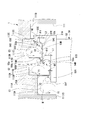
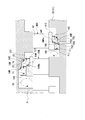
- FIG. 1 is a schematic sectional view showing a steam turbine according to an embodiment of the present invention.
- the steam turbine (rotary machine) 1 mainly includes a casing 10, a regulating valve 20, a rotating shaft 30, a stationary blade 40, and a moving blade 50.
- the rotor blade 50 is fixed to the rotary shaft 30 via a disk (not shown).
- This integrated structure is called a rotor unit for convenience.
- the casing 10 has an internal space hermetically sealed, and a radially inner side of the casing 10 is a flow path in which steam (working fluid) S flows from the upstream side toward the downstream side along the central axis direction.
- a ring-shaped partition plate outer ring 11 through which the rotary shaft 30 is inserted is firmly fixed to the inner wall surface of the casing 10.
- the adjusting valve 20 adjusts the amount and pressure of the steam S flowing into the casing 10.
- a plurality of regulating valves 20 are attached to the inside of the casing 10.
- Each regulating valve 20 includes a regulating valve chamber 21 into which steam S flows from a boiler (not shown), a valve body 22, and a valve seat 23.
- the regulating valve 20 causes the steam S to flow into the internal space of the casing 10 through the steam chamber 24 by opening the steam flow path when the valve body 22 moves away from the valve seat 23.
- the rotating shaft 30 includes a shaft main body 31 and a plurality of disks 32 extending from the outer periphery of the shaft main body 31 in the rotating shaft radial direction (hereinafter simply referred to as the radial direction).
- the rotary shaft 30 is supported by the bearing portion 60 so as to be rotatable around its central axis.
- the bearing unit 60 includes a journal bearing device 61 and a thrust bearing device 62.
- the rotary shaft 30 transmits rotational energy to a machine such as a generator (not shown).
- Each stationary blade 40 includes a stationary blade body 42 and a hub shroud 41.
- the stationary blade body 42 is provided so as to extend radially inward from the partition plate outer ring 11 fixed to the casing 10.
- the hub shroud 41 is provided on the radially inner side of the stationary blade body 42.
- the hub shroud 41 has a ring shape, and connects the stationary blade bodies 42 of the plurality of stationary blades 40 constituting the annular stationary blade group.
- the rotating shaft 30 is inserted into the casing 10 on the radially inner side of the hub shroud 41, and the hub shroud 41 is disposed with a radial clearance with respect to the rotating shaft 30.
- the annular stator blade group composed of the plurality of stator blades 40 is formed at intervals in the axial direction, converts the pressure energy of the steam S into velocity energy, and moves to the moving blade 50 side adjacent to the downstream side. To guide.
- the moving blade 50 is provided on the downstream side of each annular stationary blade group. A large number of moving blades 50 are arranged radially to constitute an annular moving blade group.
- Each blade 50 has a blade main body 52 and a tip shroud (shroud) 51A.
- the rotor blade body 52 is provided so as to extend radially outward from the disk 32 of the rotating shaft 30.
- the tip shroud 51 ⁇ / b> A is provided on the radially outer side of the rotor blade main body 52.
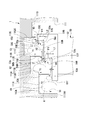
- FIG. 2 is an enlarged cross-sectional view showing a main part I in FIG.
- the tip shroud 51 ⁇ / b> A serving as the tip of the moving blade 50 is disposed so as to face the partition plate outer ring 11 with a gap K in the radial direction of the casing 10.
- the tip shroud 51A has shroud outer peripheral surfaces (outer peripheral surfaces) 53A, 53B, and 53C and step portions 54D and 54E on the radially outer side.
- the shroud outer peripheral surfaces 53A, 53B, and 53C are formed so as to extend in parallel with the central axis along the central axis of the rotating shaft 30, respectively.
- the shroud outer peripheral surfaces 53A, 53B, and 53C are provided such that their radial positions are positioned radially outward in stages from the upstream shroud outer peripheral surface 53A toward the downstream shroud outer peripheral surface 53C. That is, these shroud outer peripheral surfaces 53A, 53B, and 53C have a protruding height radially outward from the rotor blade main body 52 from the upstream side (left side in FIG. 2) to the downstream side (in FIG. 2). It is arranged so as to become gradually higher as it goes to the right side).
- the step portion 54D connects the downstream end 53q of the shroud outer peripheral surface 53A located on the upstream side and the upstream end 53p of the shroud outer peripheral surface 53B located on the downstream side.
- the step portion 54E connects the downstream end 53q of the shroud outer peripheral surface 53B located on the upstream side and the upstream end 53p of the shroud outer peripheral surface 53C located on the downstream side.
- the step portions 54D and 54E have acute angle forming surfaces 55D and 55E and inner peripheral guide surfaces 57D and 57E.
- the acute angle forming surfaces 55D and 55E are curved surfaces having an arcuate cross section extending toward the upstream side as going outward in the radial direction.
- the acute angle forming surfaces 55D and 55E are connected to the upstream end portion 53p of the shroud outer peripheral surfaces 53B and 53C located on the downstream side with an acute angle ⁇ 1. More specifically, the acute angle ⁇ 1 is an angle formed by the tangent line of the acute angle forming surfaces 55D and 55E passing through the upstream end 53p and the shroud outer peripheral surfaces 53B and 53C.
- sharp tip portions 56B and 56C sharpened at an acute angle ⁇ 1 are formed at intersections between the acute angle forming surfaces 55D and 55E and the upstream end portions 53p of the shroud outer peripheral surfaces 53B and 53C located on the downstream side.
- the inner peripheral guide surfaces 57D and 57E are formed radially inside the acute angle forming surfaces 55D and 55E.
- the inner peripheral guide surfaces 57D and 57E are curved surfaces having an arcuate cross section extending toward the downstream side in the radial direction from the downstream end portion 53q of the shroud outer peripheral surfaces 53A and 53B located on the upstream side.
- the acute angle forming surfaces 55D and 55E and the inner peripheral guide surfaces 57D and 57E are continuously formed with the same curvature radius. Further, the radial distances L1 and L2 between the connecting portions of the acute angle forming surfaces 55D and 55E and the inner peripheral guide surfaces 57D and 57E and the upstream shroud outer peripheral surfaces 53A and 53B are the upstream shroud outer peripheral surfaces 53A and 53A. It is larger than the dimension of minute gaps H1 and H2 between 53B and seal fins 15A and 15B described later. Thereby, the acute angle forming surfaces 55D and 55E are formed on the radially outer side than the tip portions of the seal fins 15A and 15B facing the shroud outer peripheral surfaces 53A and 53B located on the upstream side.
- annular groove 111 is formed at a portion facing the tip shroud 51A in the radial direction.
- the annular groove 111 corresponds to the three shroud outer peripheral surfaces 53A, 53B, 53C of the chip shroud 51A, and the three annular recesses 111A, 111B, 111C.
- the annular groove 111 further has a fourth-stage recess 111D having a diameter smaller than that of the third-stage recess 111C on the most downstream side.
- seal fins 15A are provided on an edge portion (edge portion) 112A located at the boundary between the first-step recess 111A and the second-step recess 111B.
- Seal fins 15B are provided at the edge portion 112B located at the boundary between the second-stage recess 111B and the third-stage recess 111C.
- Seal fins 15C are provided at an end portion 112C located at the boundary between the third-stage recess 111C and the fourth-stage recess 111D.
- Each of these seal fins 15A, 15B, and 15C extends radially inward toward the tip shroud 51A.
- the seal fins 15A, 15B, and 15C are provided to correspond to the shroud outer peripheral surfaces 53A, 53B, and 53C at a ratio of 1: 1. Thereby, each shroud outer peripheral surface 53A, 53B, 53C is opposed to at least one of the plurality of seal fins 15A, 15B, 15C in the radial direction.
- Each of the seal fins 15A, 15B, 15C is opposed to the corresponding shroud outer peripheral surfaces 53A, 53B, 53C in the radial direction with minute gaps H1, H2, H3.
- the dimensions of these minute gaps H1, H2, and H3 in the radial direction are safe so that they do not come into contact with each other in consideration of the thermal elongation amount of the casing 10 and the moving blade 50, the centrifugal elongation amount of the moving blade 50, and the like. Within the range, it is set to the smallest one.
- the minute gaps H1, H2, and H3 between the seal fins 15A, 15B, and 15C and the shroud outer peripheral surfaces 53A, 53B, and 53C may all have the same dimensions, or may be different from each other if necessary. Needless to say, it is possible.
- each shroud outer peripheral surface 53A, 53B, 53C and three recesses 111A, 111B, 111C of the annular groove 111 corresponding to these are provided. Cavities C1 to C3 are formed between the two. More specifically, the first cavity C1 formed on the most upstream side and corresponding to the first-stage shroud outer peripheral surface 53A includes the seal fin 15A corresponding to the first-stage shroud outer peripheral surface 53A and the upstream of the first-stage recess 111A. It is formed between the side inner wall surface 113 ⁇ / b> A and between the tip shroud 51 ⁇ / b> A and the partition plate outer ring 11.
- the second cavity C2 corresponding to the second-stage shroud outer peripheral surface 53B includes a seal fin 15B corresponding to the second-stage shroud outer peripheral surface 53B, and an inner wall surface 113B on the upstream side of the second-stage recess 111B, And between the tip fins 51 ⁇ / b> A and the partition plate outer ring 11, and between the seal fins 15 ⁇ / b> A provided on the end edge portion 112 ⁇ / b> A.
- the third cavity C3 corresponding to the third-stage shroud outer peripheral surface 53C is a downstream side of the seal fin 15C corresponding to the third-stage shroud outer peripheral surface 53C and the third-stage recess 111C provided with the seal fin 15C.
- the tip shroud 51A and the partition plate outer ring 11 between the inner wall surface 113C, the inner wall surface 113D on the upstream side of the third-stage recess 111C, and the shroud outer peripheral surface 53B provided at the end edge portion 112B. It is formed between.
- the steam S flowing into the internal space of the casing 10 sequentially passes through the annular stator blade group and the annular rotor blade group in each stage. At this time, the pressure energy is converted into velocity energy by the stationary blade 40. Most of the steam S passing through the stationary blade 40 flows between the moving blades 50 constituting the same stage. The velocity energy of the steam S is converted into rotational energy by the moving blade 50, and rotation is applied to the rotating shaft 30. On the other hand, a part (for example, several percent) of the steam S becomes so-called leaked steam that flows out from the stationary blade 40 and then flows into the annular groove 111.
- the steam S that has flowed into the annular groove 111 first flows into the first cavity C1, collides with the upstream end face 51f of the chip shroud 51A, and returns counterclockwise to rotate counterclockwise.
- a main vortex Y1 is generated.
- a part of the flow is separated from the main vortex Y1 (main flow) at the end portion on the radially outer side of the upstream end surface 51f, and thus in a direction opposite to the main vortex Y1, in this example, on the paper surface of FIG.
- the peeling vortex Y2 is generated so as to rotate clockwise at.
- Such a separation vortex Y2 exhibits a contraction effect that reduces the leakage flow (leak jet) that passes through the minute gap H1 between the seal fin 15A and the shroud outer peripheral surface 53A. That is, when the separation vortex Y2 is formed, the separation vortex Y2 causes a downflow that directs the velocity vector radially inward on the upstream side in the axial direction of the seal fin 15A. Since this down flow has an inertial force directed inward in the radial direction immediately before the minute gap H1, it exerts an effect of reducing the flow passing through the minute gap H1 inward in the radial direction (constriction effect), and the leakage flow rate becomes smaller.
- the steam S that has passed through the minute gap H1 flows into the second cavity C2, collides with the stepped portion 54D, and returns to the upstream side to generate the main vortex Y1. Further, a part of the flow is separated from the main vortex Y1 at the intersection between the acute angle forming surface 55D of the step portion 54D and the upstream end portion 53p of the shroud outer peripheral surface 53B located on the downstream side. A separation vortex Y2 is generated so as to rotate in the direction opposite to the vortex Y1.
- the steam S that has passed through the minute gap H2 flows into the third cavity C3, collides with the stepped portion 54E, and further generates a main vortex Y1 that rotates to return to the upstream side.
- a part of the flow is separated from the main vortex Y1 at the intersection between the acute angle forming surface 55E of the stepped portion 54E and the upstream end 53p of the shroud outer peripheral surface 53C located on the downstream side.
- the separation vortex Y2 is generated so as to rotate in the opposite direction.
- the separation vortex Y2 generated in the second cavity C2 and the third cavity C3 reduces the leakage flow passing through the minute gaps H2 and H3 between the seal fins 15B and 15C and the shroud outer peripheral surfaces 53B and 53C. Demonstrate the effect.
- this separation vortex Y2 causes a downflow in which the velocity vector is directed radially inward on the upstream side in the axial direction at the tip of the seal fin 15A. Since this down flow has an inertial force that is directed radially inward immediately before the minute gaps H2 and H3, the downflow has an effect of contracting radially inward with respect to the flow passing through the minute gaps H2 and H3. Demonstrates and leakage flow rate is reduced.
- a part of the steam S that has passed through the minute gaps H1 and H2 between the shroud outer peripheral surfaces 53A and 53B and the seal fins 15A and 15B is formed with an acute angle formed in the step portions 54D and 54E.
- the separation vortex Y2 is generated by separation at the intersection between the surfaces 55D and 55E and the upstream end 53p of the shroud outer peripheral surfaces 53B and 53C located on the downstream side. Since the acute angle forming surfaces 55D and 55E are connected to the upstream end portions 53p of the shroud outer peripheral surfaces 53B and 53C located on the downstream side with respect to the step portions 54D and 54E with an acute angle ⁇ 1, the separation vortex Y2 is stably generated. can do. As a result, the leakage flow of the steam S passing through the minute gaps H1 and H2 can be suppressed, and the performance degradation of the steam turbine 1 can be suppressed.
- sharp tip portions 56B and 56C sharpened at an acute angle ⁇ 1 are formed at the intersections between the acute angle forming surfaces 55D and 55E and the upstream end portions 53p of the shroud outer peripheral surfaces 53B and 53C located downstream thereof. Therefore, peeling can be promoted, and the peeling vortex Y2 can be generated stably.
- the acute angle forming surfaces 55D and 55E are formed on the outer side in the radial direction from the front ends of the seal fins 15A and 15B facing the shroud outer peripheral surfaces 53A and 53B located on the upstream side. According to such a configuration, the steam S that has passed through the minute gaps H1 and H2 between the upstream shroud outer peripheral surfaces 53A and 53B and the seal fins 15A and 15B flows along the acute angle forming surfaces 55D and 55E, and the upstream side. As a result of the turning of the flow direction, it is possible to suppress the return to the minute gaps H1, H2 side.
- the steam S can be efficiently guided toward the intersection between the upstream end 53p of the downstream shroud outer peripheral surfaces 53B and 53C and the acute angle forming surfaces 55D and 55E, and the separation vortex Y2 is stable. Can contribute to the generation.
- the stepped portions 54D and 54E are arranged on the radially inner side of the acute-angle forming surfaces 55D and 55E, and toward the downstream side from the downstream end portion 53q of the shroud outer peripheral surfaces 53A and 53B located on the upstream side toward the radially outer side. It has inner peripheral guide surfaces 57D and 57E that extend. With such a configuration, the steam S that has passed through the minute gaps H1 and H2 between the outer shroud outer peripheral surfaces 53A and 53B and the seal fins 15A and 15B is exposed to an acute angle radially outward from the inner peripheral guide surfaces 57D and 57E. It can guide efficiently toward the formation surfaces 55D and 55E.
- the tip shroud 51A of the rotor blade 50 has the same radius of curvature as the acute angle forming surfaces 55D and 55E radially inward of the acute angle forming surfaces 55D and 55E of the step portions 54D and 54E.
- the inner peripheral guide surfaces 57D and 57E made of curved surfaces are provided, the present invention is not limited to this.
- the inner peripheral guide surfaces 57D and 57E may be tapered inclined surfaces that extend toward the downstream side in the radial direction from the downstream end portion 53q of the shroud outer peripheral surfaces 53A and 53B located on the upstream side.
- FIG. 3 is an enlarged cross-sectional view showing a configuration of a moving blade of a steam turbine according to a modification of the first embodiment of the present invention.
- the tip shroud (shroud) 51B of the rotor blade 50 has a shroud outer peripheral surface 53A, which is positioned on the upstream side in the radial direction with respect to the acute angle forming surfaces 55D, 55E of the step portions 54D, 54E.
- planar inner peripheral guide surfaces 57F and 57G that extend radially outwardly orthogonal to the shroud outer peripheral surfaces 53A and 53B (or the central axis of the rotating shaft 30) may be formed. Good.
- FIG. 4 is an enlarged cross-sectional view showing the configuration of the moving blade of the steam turbine according to the second embodiment of the present invention.
- a tip shroud (shroud) 51C which is a tip portion of the moving blade 50, is radially outwardly provided with shroud outer peripheral surfaces 53A, 53B, 53C and a stepped portion 54H. , 54J.
- the step portion 54H connects the downstream end 53q of the shroud outer peripheral surface 53A located on the upstream side and the upstream end 53p of the shroud outer peripheral surface 53B located on the downstream side.
- the step portion 54J connects the downstream end 53q of the shroud outer peripheral surface 53B located on the upstream side and the upstream end 53p of the shroud outer peripheral surface 53C located on the downstream side.
- the step portions 54H and 54J have acute angle forming surfaces 55H and 55J and inner peripheral guide surfaces 57H and 57J.
- the acute angle forming surfaces 55H and 55J are formed of a flat inclined surface extending toward the upstream side as going outward in the radial direction.
- the acute angle forming surfaces 55H and 55J are connected to the upstream end portion 53p of the shroud outer peripheral surfaces 53B and 53C located on the downstream side with an acute angle ⁇ 2.
- acute angle tip portions 56H and 56J sharpened at an acute angle ⁇ 2 are formed at the intersections between the acute angle forming surfaces 55H and 55J and the upstream end portions 53p of the shroud outer peripheral surfaces 53B and 53C located on the downstream side.
- the inner peripheral guide surfaces 57H and 57J are formed radially inside the acute angle forming surfaces 55H and 55J.
- the inner peripheral guide surfaces 57H and 57J are planar inclined surfaces that extend toward the downstream side in the radial direction from the downstream end 53q of the shroud outer peripheral surfaces 53A and 53B located on the upstream side.
- the radial distances L3 and L4 between the connecting portions of the acute angle forming surfaces 55H and 55J and the inner peripheral guide surfaces 57H and 57J and the upstream shroud outer peripheral surfaces 53A and 53B are the upstream shroud outer peripheral surface 53A. , 53B and smaller gaps H1 and H2 between seal fins 15A and 15B described later.
- the acute angle forming surfaces 55H and 55J are formed on the radially outer side than the tip portions of the seal fins 15A and 15B facing the shroud outer peripheral surfaces 53A and 53B located on the upstream side.
- the acute angle forming surfaces 55H and 55J are formed on the upstream side end portion 53p of the shroud outer peripheral surfaces 53B and 53C located on the downstream side with respect to the stepped portions 54D and 54E. Since the connection is made with the acute angle ⁇ 2, the separation vortex Y2 can be stably generated. As a result, the leakage flow of the steam S passing through the minute gaps H1 and H2 can be suppressed, and the performance degradation of the steam turbine 1 can be suppressed.
- the acute angle forming surfaces 55H and 55J are formed on the outer side in the radial direction from the front ends of the seal fins 15A and 15B facing the shroud outer peripheral surfaces 53A and 53B located on the upstream side. According to such a configuration, as a result of the steam S having passed through the minute gaps H1 and H2 between the upstream shroud outer peripheral surfaces 53A and 53B and the seal fins 15A and 15B flowing along the acute angle forming surfaces 55H and 55J, It is possible to suppress the return to the minute gaps H1 and H2.
- the steam S can be efficiently guided toward the intersection between the upstream end portion 53p of the downstream shroud outer peripheral surfaces 53B and 53C and the acute angle forming surfaces 55H and 55J, and the separation vortex Y2 is stable. Can contribute to the generation.
- the stepped portions 54D and 54E are arranged on the radially inner side of the acute angle forming surfaces 55H and 55J, and toward the downstream side from the downstream end portion 53q of the shroud outer peripheral surfaces 53A and 53B located on the upstream side toward the radially outer side. Extending inner peripheral guide surfaces 57H, 57J have. With such a configuration, the steam S that has passed through the minute gaps H1 and H2 between the outer shroud outer peripheral surfaces 53A and 53B and the seal fins 15A and 15B is exposed to an acute angle radially outward from the inner peripheral guide surfaces 57H and 57J. It can guide efficiently toward the formation surfaces 55H and 55J.
- FIG. 5 is an enlarged cross-sectional view showing a configuration of a moving blade of a steam turbine according to a modification of the second embodiment of the present invention. As shown in FIG.
- the tip shroud (shroud) 51D of the rotor blade 50 has a shroud outer circumferential surface 53A, which is located on the upstream side in the radial direction with respect to the acute angle forming surfaces 55H, 55J of the step portions 54H, 54J. From the downstream end 53q of 53B, planar inner peripheral guide surfaces 57F and 57G that extend radially outwardly orthogonal to the shroud outer peripheral surfaces 53A and 53B (or the central axis of the rotating shaft 30) may be formed. Good.
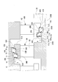
- FIG. 6 is an enlarged cross-sectional view showing the configuration of the moving blade of the steam turbine according to the third embodiment of the present invention.
- the tip shroud 51E that is the tip of the rotor blade 50 has shroud outer peripheral surfaces 53A, 53B, and 53C and stepped portions 54K and 54L on the radially outer side.
- the tip shroud 51E that is the tip of the rotor blade 50 has shroud outer peripheral surfaces 53A, 53B, and 53C and stepped portions 54K and 54L on the radially outer side.
- the step 54K connects the downstream end 53q of the shroud outer peripheral surface 53A located on the upstream side and the upstream end 53p of the shroud outer peripheral surface 53B located on the downstream side.
- the step portion 54L connects the downstream end 53q of the shroud outer peripheral surface 53B located on the upstream side and the upstream end 53p of the shroud outer peripheral surface 53C located on the downstream side.
- the step portions 54K and 54L have acute angle forming surfaces 55K and 55L and inner peripheral guide surfaces 57K and 57L.
- the acute angle forming surfaces 55K and 55L are formed of a flat inclined surface extending toward the upstream side toward the outer side in the radial direction.
- the acute angle forming surfaces 55K and 55L are connected to the upstream end portions 53p of the shroud outer peripheral surfaces 53B and 53C located at the downstream side with acute angles ⁇ 3 and ⁇ 4.
- sharp tip portions 56K and 56L sharpened at acute angles ⁇ 3 and ⁇ 4 are formed at the intersections between the acute angle forming surfaces 55K and 55L and the upstream end portions 53p of the shroud outer peripheral surfaces 53B and 53C located on the downstream side.
- the stepped portion 54K located in the second cavity C2 and the stepped portion 54L located in the third cavity C3 have different sizes of the acute angles ⁇ 3 and ⁇ 4 of the acute angle tip portions 56K and 56L.
- the outlet angles ⁇ d1 and ⁇ d2 flow along the acute angle forming surfaces 55K and 55L, and the flow of the steam S flowing out from the acute angle tip portions 56K and 56L toward the radially outer side, and the shroud outer peripheral surface 53B, It is an angle between 53C. Specifically, the density of the steam S becomes smaller toward the downstream side.
- the minute gaps H1 and H2 have the same dimensions, the flow velocity of the steam S (leak jet) passing through the minute gaps H1 and H2 increases toward the downstream side.
- the steam S that has passed through the minute gap H2 between the second stage shroud outer circumferential surface 53B and the seal fin 15B is higher than the flow velocity of the steam S that has passed through the minute gap H1 between the first stage shroud outer circumferential surface 53A and the seal fin 15A.
- the flow velocity of is larger.
- the flow toward the radially outer side of the steam S colliding with the stepped portion 54L in the third cavity C3 is more than the flow of the steam S colliding with the stepped portion 54K within the second cavity C2 toward the radially outer side. Become stronger.
- the diameter of the separation vortex Y2 formed on the radially outer side of the third-stage shroud outer circumferential surface 53C is larger than the diameter of the separation vortex Y2 formed on the radially outer side of the second-stage shroud outer circumferential surface 53B.
- the steam S flowing out from the acute angle tip portion 56L of the third stepped portion 54L is larger than the outlet angle ⁇ d1 of the flow of the steam S flowing out from the acute angle tip portion 56K of the second stepped portion 54K.
- the flow outlet angle ⁇ d2 is reduced.
- the diameter of the separation vortex Y2 formed on the radially outer side of the second-stage shroud outer peripheral surface 53B and the diameter of the separation vortex Y2 formed on the radially outer side of the third-stage shroud outer peripheral surface 53C are Equivalent size. In this way, it is possible to equalize the effect of suppressing the leakage flow of the steam S passing through the minute gaps H1, H2 by the separation vortex Y2.
- the stepped portions 54K and 54L are composed of the acute angle forming surfaces 55K and 55L and the inner peripheral guide surfaces 57K and 57L, which are inclined surfaces similar to the second embodiment. Not limited to.
- the same configuration as that of the third embodiment can also be applied to the configurations as shown in the first embodiment, its modifications, and the modifications of the second embodiment.
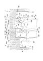
- FIG. 7 is an enlarged cross-sectional view showing a main part J in FIG.
- the stationary blade 40B of the steam turbine 1 has a stationary blade body 42 and a hub shroud (static blade shroud) 41B.
- the hub shroud 41 ⁇ / b> B is provided on the radially inner side of the stationary blade body 42.
- the hub shroud 41B has a ring shape and connects the stationary blade main bodies 42 of the plurality of stationary blades 40B constituting the annular stationary blade group.
- the rotating shaft 30 is inserted through the casing 10 on the radially inner side of the hub shroud 41 ⁇ / b> B, and a radial gap is provided with respect to the rotating shaft 30.
- the hub shroud 41B has shroud inner peripheral surfaces 43A, 43B, 43C and stationary blade step portions 44D, 44E on the radially inner side.
- the shroud inner peripheral surfaces 43 ⁇ / b> A, 43 ⁇ / b> B, and 43 ⁇ / b> C are formed so as to extend parallel to the central axis along the central axis of the rotating shaft 30.
- the shroud inner peripheral surfaces 43A, 43B, and 43C are provided such that their radial positions are located radially inward from the upstream shroud inner peripheral surface 43A toward the downstream shroud inner peripheral surface 43C. ing. That is, these shroud inner peripheral surfaces 43A, 43B, and 43C have a projecting dimension radially inward from the stationary blade body 42 from the upstream side (left side in FIG. 7) to the downstream side (in FIG. 7). It is arranged so as to gradually increase as it goes to the right).
- the stationary blade level difference portion 44D connects the downstream end 43q of the shroud inner peripheral surface 43A located on the upstream side and the upstream end 43p of the shroud inner peripheral surface 43B located on the downstream side.
- the stationary blade level difference portion 44E connects the downstream end 43q of the shroud inner peripheral surface 43B located on the upstream side and the upstream end 43p of the shroud inner peripheral surface 43C located on the downstream side.
- the stationary blade step portions 44D and 44E have stationary blade acute angle forming surfaces 45D and 45E and stationary blade inner circumferential guide surfaces 47D and 47E.
- the stator blade acute angle forming surfaces 45D and 45E are curved surfaces having an arcuate cross section extending toward the upstream side as they go radially inward.
- the stationary blade acute angle forming surfaces 45D and 45E are connected to the upstream end portion 43p of the shroud inner peripheral surfaces 43B and 43C located at the downstream side with an acute angle ⁇ 11. More specifically, the acute angle ⁇ 11 is an angle formed between the tangent line of the stationary blade acute angle forming surfaces 45D and 45E passing through the upstream end portion 43p and the shroud outer peripheral surfaces 53B and 53C.
- the stationary blade acute angle tip portions 46D and 46E pointed at the acute angle ⁇ 11 are formed at the intersections between the stationary blade acute angle forming surfaces 45D and 45E and the upstream end portions 43p of the shroud inner peripheral surfaces 43B and 43C located on the downstream side. Is formed.
- the stator vane inner peripheral guide surfaces 47D and 47E are formed on the radially outer sides of the stator blade acute angle forming surfaces 45D and 45E.
- the stator blade inner peripheral guide surfaces 47D and 47E are curved surfaces having an arcuate cross section extending toward the downstream side in the radial direction from the downstream end portion 43q of the shroud inner peripheral surfaces 43A and 43B located on the upstream side.
- the radial distances L11 and L12 between the connection portion between the stationary blade acute angle forming surfaces 45D and 45E and the stationary blade inner circumferential guide surfaces 47D and 47E and the upstream shroud inner circumferential surfaces 43A and 43B are upstream.
- the stationary blade acute angle forming surfaces 45D and 45E are formed radially inward from the tip portions of the stationary blade seal fins 16A and 16B facing the shroud inner peripheral surfaces 43A and 43B located on the upstream side.
- annular groove 311 is formed in the shaft main body 31 at a portion facing the hub shroud 41B in the radial direction.
- the annular groove 311 has three annular recesses 311A and 311B that are gradually reduced in diameter from the upstream side toward the downstream side so as to correspond to the three shroud inner peripheral surfaces 43A, 43B, and 43C of the hub shroud 41B. , 311C.
- the annular groove 311 further has a fourth-stage recess 311D having a diameter smaller than that of the third-stage recess 311C on the most downstream side.
- a stationary blade seal fin 16A is provided at an edge portion (edge portion) 312A located at the boundary between the first-stage recess 311A and the second-stage recess 311B.
- a stationary blade seal fin 16B is provided at the edge portion 312B located at the boundary between the second-stage recess 311B and the third-stage recess 311C.
- a stationary blade seal fin 16C is provided at an edge portion 312C located at the boundary between the third-stage recess 311C and the fourth-stage recess 311D.
- the stationary blade seal fins 16A, 16B, and 16C are provided so as to correspond to the shroud inner peripheral surfaces 43A, 43B, and 43C at a ratio of 1: 1. Thereby, each shroud inner peripheral surface 43A, 43B, 43C is opposed to at least one of the plurality of stationary blade seal fins 16A, 16B, 16C in the radial direction.
- the stationary blade seal fins 16A, 16B, and 16C are opposed to each other in the radial direction with minute gaps H11, H12, and H13 between the shroud inner peripheral surfaces 43A, 43B, and 43C, respectively.
- the dimensions of these minute gaps H11, H12, and H13 are within a safe range where they do not come into contact with each other in consideration of the thermal elongation amount of the casing 10 and the moving blade 50, the centrifugal elongation amount of the moving blade 50, and the like. Set to the smallest one.
- the minute gaps H11, H12, and H13 between the stationary blade seal fins 16A, 16B, and 16C and the shroud inner peripheral surfaces 43A, 43B, and 43C may all have the same dimensions, or as necessary. Needless to say, can be different from each other.
- the steam S that has flowed into the annular groove 311 first flows into the first cavity C11, collides with the upstream end face 41f of the hub shroud 41B, and generates a main vortex Y11 that rotates to return to the upstream side. .
- a part of the flow is separated from the main vortex Y11 at the radially inner end of the upstream end face 41f, so that a separation vortex Y12 is generated so as to rotate in a direction opposite to the main vortex Y11.
- Such a separation vortex Y12 exhibits a contraction effect that reduces the leakage flow passing through the minute gap H11 between the stationary blade seal fin 16A and the shroud inner peripheral surface 43A. That is, when the separation vortex Y12 is formed, the separation vortex Y12 generates a downflow (also referred to as an upflow) in which the velocity vector is directed radially outward on the upstream side in the axial direction of the tip of the stationary blade seal fin 16A.
- This down flow has an inertial force that is directed outward in the radial direction immediately before the minute gap H11. Therefore, the downflow exhibits an effect of contracting outward in the radial direction (constriction effect) with respect to the flow passing through the minute gap H11. The flow rate becomes smaller.
- the steam S that has passed through the minute gap H11 flows into the second cavity C12, collides with the stationary blade step portion 44D, and returns to the upstream side to generate the main vortex Y11. Furthermore, a part of the flow is separated from the main vortex Y11 at the intersection between the stationary blade acute angle forming surface 45D of the stationary blade step portion 44D and the upstream end portion 43p of the shroud inner peripheral surface 43B located on the downstream side. As a result, a separation vortex Y12 that rotates in a direction opposite to the main vortex Y11 is generated.
- the steam S that has passed through the minute gap H12 flows into the third cavity C13, collides with the stationary blade step portion 44E, and further generates a main vortex Y11 that rotates to return to the upstream side.
- a separation vortex Y12 rotating in the opposite direction to the main vortex Y11 is generated.
- the separation vortex Y12 generated in the second cavity C12 and the third cavity C13 reduces the leakage flow passing through the minute gaps H12 and H13 between the stationary blade seal fins 16B and 16C and the shroud inner peripheral surfaces 43B and 43C. Demonstrate the effect of contraction. That is, when the separation vortex Y12 is formed, the separation vortex Y12 causes a downflow in which the velocity vector is directed radially outward on the upstream side in the axial direction of the tips of the stationary blade seal fins 16B and 16C. This downflow has an inertial force that is directed outward in the radial direction immediately before the minute gaps H12 and H13. Therefore, the downflow has an effect of contracting radially outward with respect to the flow passing through the minute gaps H12 and H13. Demonstrates and leakage flow rate is reduced.
- the stationary blade step portions 44D and 44E provided on the hub shroud 41 of the stationary blade 40 include the stationary blade acute angle forming surfaces 45D and 45E.
- the stationary blade acute angle forming surfaces 45D and 45E are connected to the upstream end portions 43p of the shroud inner peripheral surfaces 43A, 43B, and 43C located at the downstream side with respect to the stationary blade step portions 44D and 44E.
- the separation vortex Y12 can be generated stably. As a result, it is possible to suppress the leakage flow that passes through the minute gaps H12 and H13, and to suppress the performance degradation of the steam turbine 1.
- the present invention is not limited to the above-described embodiments, and includes various modifications made to the above-described embodiments without departing from the spirit of the present invention. That is, the specific shapes, configurations, and the like given in the embodiment are merely examples, and can be changed as appropriate.
- the present invention is applied to the final stage moving blade 50 and the stationary blade 40, but the present invention may be applied to other stages of the moving blade 50 and the stationary blade 40.
- a configuration as shown in FIG. 8 can be adopted. That is, as in the first embodiment, in the tip shroud 51 ⁇ / b> A of the moving blade 50, the shroud outer peripheral surfaces 53 ⁇ / b> A, 53 ⁇ / b> B, and 53 ⁇ / b> C have a protruding height radially outward from the moving blade body 52. As it goes from the upstream side (the left side in FIG. 8) to the downstream side (the right side in FIG. 8), it is arranged so as to become gradually higher.
- the shroud inner peripheral surfaces 43A, 43B, and 43C are protruded radially inward from the stationary blade body 42 in the upstream side in the axial direction of the rotary shaft 30 (left side in FIG. 8). It is arranged so as to gradually become smaller in the direction from the downstream side to the downstream side (right side in FIG. 8).
- the third-stage recess 311C is located on the radially inner side of the fourth-stage recess 311D. Further, the bottom surface of the first-stage recess 311A is disposed at the same radial position as the bottom surface of the second-stage recess 311B.
- the tip shroud 51F of the moving blade 50 has a stepped portion 54M.
- the moving blade 50B has a protruding height from the moving blade body 52 radially outward from the upstream side (left side in FIG. 9) to the downstream side (right side in FIG. 9). It is arranged so as to gradually become lower as it goes.
- the seal fin 15A is provided at the position of the upstream end portion of the tip shroud 51F. Further, the seal fin 15B is provided at the position of the guide surface 54Ma that forms the stepped portion 54M and faces the downstream side.
- a seal fin 15C is provided at the position of the downstream end of the tip shroud 51F.
- the seal fins 15A, 15B, and 15C protrude radially outward from the tip shroud 51F.
- the partition plate outer ring 11 has stepped portions 54D and 54E at portions facing the tip shroud 51F in the radial direction. Due to these stepped portions 54D and 54E, the radial position of the partition plate outer ring 11 is positioned gradually inward in the radial direction from the upstream side to the downstream side in the axial direction of the rotating shaft 30.
- the hub shroud 41C of the stationary blade 40C has a stationary blade step portion 44F. Due to the stationary blade step portion 44F, the stationary blade 40C has a projecting height from the stationary blade body 42 to the radially inner side that gradually decreases from the upstream side to the downstream side in the axial direction of the rotating shaft 30. It is arranged.
- a seal fin 16A is provided at the position of the upstream end of the hub shroud 41C.
- the seal fin 16B is provided at a position of the guide surface 44Fa that forms the stationary blade step portion 44F and faces the downstream side.
- a seal fin 16C is provided at the position of the downstream end of the hub shroud 41C.
- the seal fins 16A, 16B, and 16C protrude radially inward from the hub shroud 41C.
- the shaft body 31 has step portions 44D and 44E at portions that face the hub shroud 41C in the radial direction. Due to these stepped portions 44D and 44E, the radial position of the outer peripheral surface of the shaft body 31 is positioned gradually inward in the radial direction as it goes from the upstream side to the downstream side in the axial direction of the rotating shaft 30.
- the present invention is applied to a condensing steam turbine.
- the present invention is applied to other types of steam turbines, for example, turbine types such as a two-stage extraction turbine, an extraction turbine, and an air-mixing turbine. It can also be applied.
- the present invention is applied to the steam turbine 1, but the present invention can also be applied to a gas turbine, and furthermore, the present invention can be applied to all the rotor blades. it can.
- the rotor blade, the rotor unit, and the rotating machine according to the present invention it is possible to suppress the leakage flow passing through the minute gap and suppress the performance degradation.
Landscapes
- Engineering & Computer Science (AREA)
- General Engineering & Computer Science (AREA)
- Mechanical Engineering (AREA)
- Chemical & Material Sciences (AREA)
- Combustion & Propulsion (AREA)
- Turbine Rotor Nozzle Sealing (AREA)
- Sealing Using Fluids, Sealing Without Contact, And Removal Of Oil (AREA)
Abstract
回転機械(1)において、動翼(50)のチップシュラウド(51A)が、径方向位置が上流側から下流側に向かって段階的に径方向外側に位置するよう複数が設けられたシュラウド外周面(53A,53B,53C)と、隣接するシュラウド外周面(53A,53B,53C)どうしを接続する段差部(54D,54E)と、を有する。段差部(54D,54E)は、径方向外側に向かうに従って上流側に向かって延び、下流側に位置するシュラウド外周面(53A,53B,53C)の上流側端部(53p)に鋭角θ1をもって接続される鋭角形成面(55D,55E)を有する。
Description
本発明は、動翼、ロータユニット、及び、回転機械に関する。
本願は、2017年2月28日に日本に出願された特願2017-037753号について優先権を主張し、その内容をここに援用する。
本願は、2017年2月28日に日本に出願された特願2017-037753号について優先権を主張し、その内容をここに援用する。
蒸気タービン、ガスタービン等の回転機械において、ケーシングと、ケーシングの内部に回転自在に設けられた回転軸と、ケーシングの内周部に固定配置された静翼と、この静翼の下流側において回転軸に放射状に設けられた動翼と、を備えたものが知られている。
例えば蒸気タービンの場合、蒸気の圧力エネルギーを静翼によって速度エネルギーに変換し、この速度エネルギーを動翼によって回転エネルギー(機械エネルギー)に変換している。また、動翼内で圧力エネルギーが速度エネルギーに変換され、蒸気が噴出する反動力により回転エネルギー(機械エネルギー)に変換される場合もある。
例えば蒸気タービンの場合、蒸気の圧力エネルギーを静翼によって速度エネルギーに変換し、この速度エネルギーを動翼によって回転エネルギー(機械エネルギー)に変換している。また、動翼内で圧力エネルギーが速度エネルギーに変換され、蒸気が噴出する反動力により回転エネルギー(機械エネルギー)に変換される場合もある。
この種の回転機械では、動翼の先端部と、動翼を囲繞して蒸気の流路を形成するケーシングとの間に径方向の隙間が形成されている。また、静翼の先端部と回転軸との間にも、径方向の隙間が形成されている。これらの隙間を蒸気等の作動流体が通過(漏洩)することがある。動翼の先端部とケーシングとの隙間を通過する作動流体は、動翼の回転に寄与しない。また、静翼の先端部と回転軸との隙間を通過する作動流体は、静翼による圧力エネルギーの速度エネルギーへの変換に寄与せず、下流側の動翼に対して回転力をほとんど付与しない。
したがって、回転機械の性能向上のためには、前記の隙間を通過する漏洩蒸気の量を低減することが重要となる。
したがって、回転機械の性能向上のためには、前記の隙間を通過する漏洩蒸気の量を低減することが重要となる。
例えば、特許文献1、2には、動翼又は静翼のブレードの先端部に形成され、段差面を有したステップ部と、ケーシングに設けられ、ステップ部に向かって延出し、このステップ部との間に微小隙間を形成するシールフィンと、を備える構成が開示されている。
このような構成においては、ステップ部とシールフィンとの微小隙間を通過した作動流体を段差面に衝突させ、流動抵抗を増大させることで、ステップ部とシールフィンとの微小隙間を通り抜ける漏れ流れを低減する。また、ステップ部の段差面に沿って径方向に流れる流体の主流の一部は、段差面の端縁部において流体の主流から剥離し、剥離渦が生成される。この剥離渦によって、ステップ部とシールフィンとの微小隙間を通り抜けようとする漏れ流れを径方向に縮める縮流効果を発揮することで、微小隙間を通り抜ける漏れ流れを低減する。
このような構成においては、ステップ部とシールフィンとの微小隙間を通過した作動流体を段差面に衝突させ、流動抵抗を増大させることで、ステップ部とシールフィンとの微小隙間を通り抜ける漏れ流れを低減する。また、ステップ部の段差面に沿って径方向に流れる流体の主流の一部は、段差面の端縁部において流体の主流から剥離し、剥離渦が生成される。この剥離渦によって、ステップ部とシールフィンとの微小隙間を通り抜けようとする漏れ流れを径方向に縮める縮流効果を発揮することで、微小隙間を通り抜ける漏れ流れを低減する。
しかしながら、上記したような構成において、ステップ部に形成された段差面の端縁部(エッジ)は、製作時の加工誤差、丸め加工や面取加工、長期間の使用による摩耗等によって、剥離渦を安定的に生成できなくなる場合がある。すると、剥離渦による縮流効果が想定よりも減少し、微小隙間を通り抜ける漏れ流れが増えて回転機械の性能が低下する場合がある。
本発明は、上記事情に鑑みてなされたものであり、微小隙間を通り抜ける漏れ流れを抑え、性能低下を抑えることができる動翼、ロータユニット、及び、回転機械を提供することを目的とする。
本発明は、上記課題を解決するため、以下の手段を採用する。
本発明の第一の態様では、動翼は、回転機械の回転軸から径方向外側に向かって延びるよう設けられた動翼本体、及び、前記動翼本体の径方向外側に設けられたシュラウドを有する動翼において、前記シュラウドは、前記回転軸の中心軸方向に沿って流れる作動流体の上流側から下流側に向かって段階的に径方向外側に位置するように複数設けられた外周面と、前記上流側に位置する前記外周面の下流側端部と前記下流側に位置する前記外周面の上流側端部とを接続する段差部と、を有し、前記段差部は、径方向外側に向かうに従って前記上流側に向かって延び、前記下流側に位置する前記外周面の前記上流側端部に鋭角をもって接続される鋭角形成面を有する。
本発明の第一の態様では、動翼は、回転機械の回転軸から径方向外側に向かって延びるよう設けられた動翼本体、及び、前記動翼本体の径方向外側に設けられたシュラウドを有する動翼において、前記シュラウドは、前記回転軸の中心軸方向に沿って流れる作動流体の上流側から下流側に向かって段階的に径方向外側に位置するように複数設けられた外周面と、前記上流側に位置する前記外周面の下流側端部と前記下流側に位置する前記外周面の上流側端部とを接続する段差部と、を有し、前記段差部は、径方向外側に向かうに従って前記上流側に向かって延び、前記下流側に位置する前記外周面の前記上流側端部に鋭角をもって接続される鋭角形成面を有する。
このような構成によれば、動翼の段差部は、段差部に対して上流側の外周面とともに、例えばシールフィンとの隙間を通過した作動流体を径方向外側に導き主渦を形成する。また段差部の鋭角形成面によって径方向外側に導かれる作動流体の一部は、鋭角形成面とその下流側に位置する外周面の上流側端部との交差部で、作動流体の主流から剥離して剥離渦を生成する。鋭角形成面は、段差部に対して下流側に位置する外周面の上流側端部に鋭角をもって接続されているので、このような剥離渦を安定的に生成することができる。
本発明の第二の態様では、上記第一の態様において、前記鋭角形成面と前記下流側に位置する前記外周面の前記上流側端部との交差部に、鋭角に尖った鋭角先端部が形成されていてもよい。
このような構成によれば、鋭角形成面と、下流側の外周面の上流側端部との交差部が、鋭角に尖った鋭角先端部であるので、剥離渦を安定的に生成することができる。
本発明の第三の態様では、上記第一又は第二の態様において、前記段差部は、前記鋭角形成面の径方向内側に、前記上流側に位置する前記外周面の前記下流側端部から径方向外側に向かうに従って前記下流側に向かって延びる内周案内面を有していてもよい。
このように構成することで、上流側の外周面とシールフィンとの隙間を通過した作動流体を、内周案内面から径方向外側の鋭角形成面に向かって効率良く案内することができる。
本発明の第四の態様では、上記第一から第三の態様において、複数の前記外周面と前記鋭角形成面との間の前記鋭角の角度が、前記上流側の前記外周面から前記下流側の前記外周面に向かって大きくなってもよい。
複数の外周面を備えるシュラウドにおいて、作動流体の密度は、下流側に向かうほど小さくなる。すると、シュラウドの外周面と、例えばシールフィンとの隙間を通過する作動流体の流速は、上流側よりも下流側の外周面上で大きくなる。そこで、外周面と鋭角形成面との間の鋭角の角度を、下流側で上流側よりも大きくすることで、鋭角形成面とその下流側に位置する外周面の上流側端部との交差部で作動流体の主流から剥離して生成される剥離渦の直径を小さくすることができる。これによって、複数の外周面において、例えばシールフィンとの隙間を通り抜ける作動流体の漏れ流れに対する、剥離渦による抑制効果の均等化を図ることができる。
本発明の第五の態様では、ロータユニットは、前記回転軸と上記第一から第四のいずれかの態様における動翼とを備えている。
本発明の第五の態様によれば、上記動翼を備えることで、鋭角形成面は段差部に対して下流側に位置する外周面の上流側端部に鋭角をもって接続されている。よって、作動流体の主流から剥離する剥離渦を安定的に生成することができる。
本発明の第六の態様では、回転機械は、前記シュラウドの径方向外側に配置され、その径方向内側を作動流体が前記中心軸方向に沿って上流側から下流側に向かって流れるケーシングと、前記中心軸方向に沿って間隔をあけて複数設けられ、それぞれ、前記ケーシングから径方向内側に向かって突出するシールフィンと、上記第五の態様のロータユニットと、を備えている。
本発明の第六の態様によれば、上記ロータユニットを備えることで、鋭角形成面は段差部に対して下流側に位置する外周面の上流側端部に鋭角をもって接続されている。よって、作動流体の主流から剥離する剥離渦を安定的に生成することができる。
本発明の第七の態様では、上記第六の態様において、前記鋭角形成面は、前記上流側に位置する前記外周面に対向する前記シールフィンの先端部よりも、径方向外側に形成されていてもよい。
このような構成によれば、上流側の外周面とシールフィンとの隙間を通過した作動流体が、鋭角形成面に沿って流れ、流れ方向が上流側に転向された結果、上流側の外周面とシールフィンとの隙間側に戻るのを抑えることができる。これにより、作動流体を、下流側の外周面の上流側端部と鋭角形成面との交差部分に向かって効率良く案内することができる。
本発明の第八の態様では、上記第六又は七の態様において、前記鋭角形成面は、前記上流側の前記外周面と前記シールフィンとの隙間を通過した作動流体を径方向外側に導くとともに、前記鋭角形成面と前記下流側に位置する前記外周面の前記上流側端部との交差部で、径方向外側に導かれた前記作動流体の一部を前記作動流体の主流から剥離させて剥離渦を生成してもよい。
本発明の第九の態様によれば、回転機械は、中心軸回りに回転する回転軸と、前記回転軸から径方向外側に向かって延びるよう設けられた動翼本体、及び、前記動翼本体の径方向外側に設けられたシュラウドを有する動翼と、前記シュラウドの径方向外側に配置され、その径方向内側を作動流体が前記中心軸方向に沿って上流側から下流側に向かって流れるケーシングと、前記ケーシングから径方向内側に向かって延びるよう設けられた静翼本体、及び前記静翼本体の径方向内側に設けられた静翼シュラウドを有する静翼と、前記中心軸方向に沿って間隔をあけて複数設けられ、それぞれ、前記回転軸の外周面から径方向外側に向かって突出する静翼シールフィンと、を備え、前記静翼シュラウドは、径方向位置が前記上流側から前記下流側に向かって段階的に径方向内側に位置するよう複数が設けられるとともに、それぞれが複数の前記静翼シールフィンの少なくとも一つに対して径方向外側で間隔を隔てて対向し、前記中心軸に沿って延びるシュラウド内周面と、前記上流側に位置する前記シュラウド内周面の下流側端部と前記下流側に位置する前記シュラウド内周面の上流側端部とを接続する静翼段差部と、を有し、前記静翼段差部は、径方向内側に向かうに従って前記上流側に向かって延び、前記下流側に位置する前記シュラウド内周面の前記上流側端部に鋭角をもって接続される静翼鋭角形成面を有する。
このような構成によれば、静翼の静翼シュラウドに設けられた静翼段差部は、静翼段差部に対して上流側のシュラウド内周面とともに、静翼シールフィンとの隙間を通過した作動流体を径方向内側に導いて主渦を形成する。また静翼段差部の静翼鋭角形成面によって径方向内側に導かれた作動流体の一部は、静翼鋭角形成面とその下流側に位置するシュラウド内周面の上流側端部との交差部で、作動流体の主流から剥離して剥離渦を生成する。静翼鋭角形成面は、静翼段差部に対して下流側に位置するシュラウド内周面の上流側端部に鋭角をもって接続されるため、このような剥離渦を安定的に生成することができる。
本発明の第十の態様によれば、上記第九の態様において回転機械は、前記中心軸方向に沿って間隔をあけて複数設けられ、それぞれ、前記ケーシングから径方向内側に向かって突出するシールフィンをさらに備え、前記動翼の前記シュラウドは、径方向位置が前記上流側から下流側に向かって段階的に径方向外側に位置するよう複数が設けられるとともに、それぞれが複数の前記シールフィンの少なくとも一つに対して径方向内側で間隔を隔てて対向し、前記中心軸に沿って延びる外周面と、上流側に位置する前記外周面の下流側端部と下流側に位置する前記外周面の上流側端部とを接続する段差部と、を有し、前記段差部は、径方向外側に向かうに従って上流側に向かって延び、下流側に位置する前記外周面の前記上流側端部に鋭角をもって接続される鋭角形成面を有していてもよい。
本発明の第十一の態様によれば、回転機械は、中心軸回りに回転する回転軸と、前記回転軸から径方向外側に向かって延びるよう設けられた動翼本体、及び、前記動翼本体の径方向外側に設けられたシュラウドを有する動翼と、前記シュラウドの径方向外側に配置され、その径方向内側を作動流体が前記中心軸方向に沿って上流側から下流側に向かって流れるケーシングと、前記中心軸方向に沿って間隔をあけて複数設けられ、それぞれ、前記シュラウドから径方向外側に向かって突出するシールフィンと、を備え、前記ケーシングは、径方向位置が前記上流側から下流側に向かって段階的に径方向外側に位置するよう複数が設けられるとともに、それぞれが複数の前記シールフィンの少なくとも一つに対して径方向外側で間隔を隔てて対向し、前記中心軸に沿って延びる内周面と、上流側に位置する前記内周面の下流側端部と下流側に位置する前記内周面の上流側端部とを接続する段差部と、を有し、前記段差部は、径方向内側に向かうに従って上流側に向かって延び、下流側に位置する前記内周面の前記上流側端部に鋭角をもって接続される鋭角形成面を有する。
本発明の第十二の態様によれば、回転機械は、中心軸回りに回転する回転軸と、前記回転軸から径方向外側に向かって延びるよう設けられた動翼本体、及び、前記動翼本体の径方向外側に設けられたシュラウドを有する動翼と、前記シュラウドの径方向外側に配置され、その径方向内側を作動流体が前記中心軸方向に沿って上流側から下流側に向かって流れるケーシングと、前記ケーシングから径方向内側に向かって延びるよう設けられた静翼本体、及び前記静翼本体の径方向内側に設けられた静翼シュラウドを有する静翼と、前記中心軸方向に沿って間隔をあけて複数設けられ、それぞれ、前記静翼シュラウドから径方向内側に向かって突出する静翼シールフィンと、を備え、前記回転軸は、径方向位置が前記上流側から前記下流側に向かって段階的に径方向外側に位置するよう複数が設けられるとともに、それぞれが複数の前記静翼シールフィンの少なくとも一つに対して径方向内側で間隔を隔てて対向し、前記中心軸に沿って延びる外周面と、前記上流側に位置する前記外周面の下流側端部と前記下流側に位置する前記外周面の上流側端部とを接続する段差部と、を有し、前記段差部は、径方向外側に向かうに従って前記上流側に向かって延び、前記下流側に位置する前記外周面の前記上流側端部に鋭角をもって接続される鋭角形成面を有する。
本発明に係る動翼、ロータユニット、及び、回転機械によれば、微小隙間を通り抜ける漏れ流れを抑え、性能低下を抑えることが可能となる。
以下、本発明の実施形態に係る蒸気タービン(回転機械)を図面に基づき説明する。(第一実施形態)
図1は、本発明の実施形態に係る蒸気タービンを示す概略構成断面図である。
図1に示すように、蒸気タービン(回転機械)1は、ケーシング10と、調整弁20と、回転軸30と、静翼40と、動翼50と、を主たる構成としている。なお、動翼50は、図示しないディスクを介して回転軸30に固定されている。この一体構成物を、便宜上、ロータユニットと呼称する。
図1は、本発明の実施形態に係る蒸気タービンを示す概略構成断面図である。
図1に示すように、蒸気タービン(回転機械)1は、ケーシング10と、調整弁20と、回転軸30と、静翼40と、動翼50と、を主たる構成としている。なお、動翼50は、図示しないディスクを介して回転軸30に固定されている。この一体構成物を、便宜上、ロータユニットと呼称する。
ケーシング10は、内部空間が気密に封止されているとともに、その径方向内側が蒸気(作動流体)Sが中心軸方向に沿って上流側から下流側に向かって流れる流路とされている。このケーシング10の内壁面には、回転軸30が挿通されたリング状の仕切板外輪11が強固に固定されている。
調整弁20は、ケーシング10に流入する蒸気Sの量と圧力を調整する。調整弁20は、ケーシング10の内部に複数個取り付けられている。各調整弁20は、図示しないボイラから蒸気Sが流入する調整弁室21と、弁体22と、弁座23とを備えている。調整弁20は、弁体22が弁座23から離れると蒸気流路が開くことによって、蒸気室24を介して蒸気Sをケーシング10の内部空間に流入させる。
回転軸30は、軸本体31と、この軸本体31の外周から回転軸径方向(以下、単に径方向という)に延出した複数のディスク32とを備えている。回転軸30は、軸受部60によって、その中心軸回りに回転可能に支持されている。軸受部60は、ジャーナル軸受装置61およびスラスト軸受装置62を備えている。
この回転軸30は、不図示の発電機等の機械に回転エネルギーを伝達する。
この回転軸30は、不図示の発電機等の機械に回転エネルギーを伝達する。
静翼40は、回転軸30を囲繞するように放射状に多数配置されて環状静翼群を構成している。
各静翼40は、静翼本体42と、ハブシュラウド41と、を有する。静翼本体42は、ケーシング10に固定された仕切板外輪11から径方向内側に向かって延びるよう設けられている。ハブシュラウド41は、静翼本体42の径方向内側に設けられている。ハブシュラウド41は、リング状をなし、環状静翼群を構成する複数の静翼40の静翼本体42を連結する。ハブシュラウド41の径方向内側でケーシング10には回転軸30が挿通され、ハブシュラウド41は回転軸30に対して径方向の隙間をあけて配設されている。
これら複数の静翼40からなる環状静翼群は、軸方向に間隔をあけて六つ形成されており、蒸気Sの圧力エネルギーを速度エネルギーに変換して、下流側に隣接する動翼50側に案内する。
動翼50は、各環状静翼群の下流側に設けられている。動翼50は、放射状に多数配置されて環状動翼群を構成している。
各動翼50は、動翼本体52と、チップシュラウド(シュラウド)51Aと、を有する。動翼本体52は、回転軸30が有するディスク32から径方向外側に向かって延びるよう設けられている。チップシュラウド51Aは、動翼本体52の径方向外側に設けられている。
各動翼50は、動翼本体52と、チップシュラウド(シュラウド)51Aと、を有する。動翼本体52は、回転軸30が有するディスク32から径方向外側に向かって延びるよう設けられている。チップシュラウド51Aは、動翼本体52の径方向外側に設けられている。
図2は、図1における要部Iを示す拡大断面図である。
図2に示すように、動翼50の先端部となるチップシュラウド51Aは、ケーシング10の径方向において仕切板外輪11と隙間Kを介して対向して配置されている。
チップシュラウド51Aは、径方向外側に、シュラウド外周面(外周面)53A,53B,53Cと、段差部54D,54Eを有している。
図2に示すように、動翼50の先端部となるチップシュラウド51Aは、ケーシング10の径方向において仕切板外輪11と隙間Kを介して対向して配置されている。
チップシュラウド51Aは、径方向外側に、シュラウド外周面(外周面)53A,53B,53Cと、段差部54D,54Eを有している。
シュラウド外周面53A,53B,53Cは、それぞれ、回転軸30の中心軸に沿って中心軸に平行に延びるよう形成されている。シュラウド外周面53A,53B,53Cは、その径方向位置が、上流側のシュラウド外周面53Aから下流側のシュラウド外周面53Cに向かって、段階的に径方向外側に位置するよう設けられている。すなわち、これらシュラウド外周面53A,53B,53Cは、動翼本体52から径方向外側への突出高さが、回転軸30の軸方向の上流側(図2における左側)から下流側(図2における右側)に向かうに従って、漸次段階的に高くなるように配設されている。
段差部54Dは、その上流側に位置するシュラウド外周面53Aの下流側端部53qと、下流側に位置するシュラウド外周面53Bの上流側端部53pとを接続する。段差部54Eは、その上流側に位置するシュラウド外周面53Bの下流側端部53qと、下流側に位置するシュラウド外周面53Cの上流側端部53pとを接続する。
段差部54D,54Eは、鋭角形成面55D,55Eと、内周案内面57D,57Eと、を有している。
鋭角形成面55D,55Eは、径方向外側に向かうに従って上流側に向かって延びる断面円弧状の湾曲面からなる。鋭角形成面55D,55Eは、下流側に位置するシュラウド外周面53B,53Cの上流側端部53pに鋭角θ1をもって接続される。鋭角θ1はより詳細には上流側端部53pを通る鋭角形成面55D,55Eの接線と、シュラウド外周面53B,53Cとのなす角である。
これにより、鋭角形成面55D,55Eと、その下流側に位置するシュラウド外周面53B,53Cの上流側端部53pとの交差部に、鋭角θ1に尖った鋭角先端部56B,56Cが形成されている。
これにより、鋭角形成面55D,55Eと、その下流側に位置するシュラウド外周面53B,53Cの上流側端部53pとの交差部に、鋭角θ1に尖った鋭角先端部56B,56Cが形成されている。
内周案内面57D,57Eは、鋭角形成面55D,55Eの径方向内側に形成されている。内周案内面57D,57Eは、上流側に位置するシュラウド外周面53A,53Bの下流側端部53qから径方向外側に向かうに従って下流側に向かって延びる断面円弧状の湾曲面からなる。
ここで、鋭角形成面55D,55Eと、内周案内面57D,57Eとは、同一の曲率半径で連続して形成されている。
また、鋭角形成面55D,55Eと内周案内面57D,57Eとの接続部と、上流側のシュラウド外周面53A,53Bとの径方向の間隔L1,L2は、上流側のシュラウド外周面53A,53Bと後述するシールフィン15A,15Bとの微小隙間H1,H2の寸法よりも大きい。これにより、鋭角形成面55D,55Eは、上流側に位置するシュラウド外周面53A,53Bに対向するシールフィン15A,15Bの先端部よりも、径方向外側に形成されている。
また、鋭角形成面55D,55Eと内周案内面57D,57Eとの接続部と、上流側のシュラウド外周面53A,53Bとの径方向の間隔L1,L2は、上流側のシュラウド外周面53A,53Bと後述するシールフィン15A,15Bとの微小隙間H1,H2の寸法よりも大きい。これにより、鋭角形成面55D,55Eは、上流側に位置するシュラウド外周面53A,53Bに対向するシールフィン15A,15Bの先端部よりも、径方向外側に形成されている。
仕切板外輪11には、チップシュラウド51Aに対して径方向で対向する部位に、環状溝111が形成されている。環状溝111は、チップシュラウド51Aの三つのシュラウド外周面53A,53B,53Cに対応するように、上流側から下流側に向かって、段差により漸次拡径された三つの環状の凹部111A,111B,111Cを有している。環状溝111は、さらに、最下流側に、三段目の凹部111Cよりも縮径された四段目の凹部111Dを有している。
ここで、一段目の凹部111Aと二段目の凹部111Bとの境界に位置する端縁部(エッジ部)112Aには、シールフィン15Aが設けられている。二段目の凹部111Bと三段目の凹部111Cとの境界に位置する端縁部112Bには、シールフィン15Bが設けられている。三段目の凹部111Cと四段目の凹部111Dとの境界に位置する端縁部112Cには、シールフィン15Cが設けられている。これらシールフィン15A,15B,15Cは、それぞれ、チップシュラウド51Aに向けて径方向内側に延出している。この実施形態では、シールフィン15A,15B,15Cは、シュラウド外周面53A,53B,53Cに1:1で対応するように設けられている。これにより、シュラウド外周面53A,53B,53Cは、それぞれが複数のシールフィン15A,15B,15Cの少なくとも一つに径方向で対向している。
各シールフィン15A,15B,15Cは、それぞれ対応するシュラウド外周面53A,53B,53Cとの間に、微小隙間H1,H2,H3を有して径方向で対向している。これら微小隙間H1,H2,H3の径方向の各寸法は、ケーシング10や動翼50の熱伸び量、動翼50の遠心伸び量等を考慮した上で、両者が接触することがない安全な範囲内で、最小のものに設定されている。
ここで、シールフィン15A,15B,15Cと、シュラウド外周面53A,53B,53Cとの微小隙間H1,H2,H3は、全て同じ寸法であってもよいし、必要に応じて、これらを互いに異ならせることが可能であることはいうまでもない。
ここで、シールフィン15A,15B,15Cと、シュラウド外周面53A,53B,53Cとの微小隙間H1,H2,H3は、全て同じ寸法であってもよいし、必要に応じて、これらを互いに異ならせることが可能であることはいうまでもない。
このような構成のもとに、チップシュラウド51Aと仕切板外輪11との間には、各シュラウド外周面53A,53B,53Cと、これらに対応する環状溝111の三つの凹部111A,111B,111Cとの間にキャビティC1~C3が形成されている。
より詳しくは、最上流側に形成され、一段目のシュラウド外周面53Aに対応する第一のキャビティC1は、一段目のシュラウド外周面53Aに対応するシールフィン15Aと、一段目の凹部111Aの上流側の内壁面113Aとの間で、かつチップシュラウド51Aと仕切板外輪11との間に形成されている。
より詳しくは、最上流側に形成され、一段目のシュラウド外周面53Aに対応する第一のキャビティC1は、一段目のシュラウド外周面53Aに対応するシールフィン15Aと、一段目の凹部111Aの上流側の内壁面113Aとの間で、かつチップシュラウド51Aと仕切板外輪11との間に形成されている。
また、二段目のシュラウド外周面53Bに対応する第二のキャビティC2は、二段目のシュラウド外周面53Bに対応するシールフィン15Bと、二段目の凹部111Bの上流側の内壁面113B、および端縁部112Aに設けられているシールフィン15Aとの間で、かつチップシュラウド51Aと仕切板外輪11との間に形成されている。
さらに、三段目のシュラウド外周面53Cに対応する第三のキャビティC3は、三段目のシュラウド外周面53Cに対応するシールフィン15C、およびこれが設けられている三段目の凹部111Cの下流側の内壁面113Cと、三段目の凹部111Cの上流側の内壁面113D、および端縁部112Bに設けられているシュラウド外周面53Bとの間で、かつチップシュラウド51Aと仕切板外輪11との間に形成されている。
さらに、三段目のシュラウド外周面53Cに対応する第三のキャビティC3は、三段目のシュラウド外周面53Cに対応するシールフィン15C、およびこれが設けられている三段目の凹部111Cの下流側の内壁面113Cと、三段目の凹部111Cの上流側の内壁面113D、および端縁部112Bに設けられているシュラウド外周面53Bとの間で、かつチップシュラウド51Aと仕切板外輪11との間に形成されている。
(蒸気タービンの動作)
次に、蒸気タービン1の動作について説明する。
まず、調整弁20(図1参照)を開状態とすると、図示しないボイラから蒸気Sがケーシング10の内部空間に流入する。
次に、蒸気タービン1の動作について説明する。
まず、調整弁20(図1参照)を開状態とすると、図示しないボイラから蒸気Sがケーシング10の内部空間に流入する。
ケーシング10の内部空間に流入した蒸気Sは、各段における環状静翼群と環状動翼群とを順次通過する。この際には、圧力エネルギーが静翼40によって速度エネルギーに変換される。静翼40を経た蒸気Sのうちの大部分が同一の段を構成する動翼50間に流入する。蒸気Sの速度エネルギーが動翼50により回転エネルギーに変換されて、回転軸30に回転が付与される。一方、蒸気Sのうちの一部(例えば、数%)は、静翼40から流出した後、環状溝111内に流入する、所謂漏洩蒸気となる。
ここで、環状溝111内に流入した蒸気Sは、まず、第一のキャビティC1に流入し、チップシュラウド51Aの上流側端面51fに衝突し、上流側に戻るようにして、反時計回りに回る主渦Y1を生じる。
その際、上流側端面51fの径方向外側の端部において、主渦Y1(主流)から一部の流れが剥離されることにより、この主渦Y1と反対方向、本例では図2の紙面上にて時計回りに回るように、剥離渦Y2が生じる。
その際、上流側端面51fの径方向外側の端部において、主渦Y1(主流)から一部の流れが剥離されることにより、この主渦Y1と反対方向、本例では図2の紙面上にて時計回りに回るように、剥離渦Y2が生じる。
このような剥離渦Y2は、シールフィン15Aとシュラウド外周面53Aとの間の微小隙間H1を通り抜ける漏れ流れ(リークジェット)を低減する、縮流効果を発揮する。
すなわち、剥離渦Y2が形成されると、この剥離渦Y2には、シールフィン15Aの軸方向上流側において、速度ベクトルを径方向内側に向けるダウンフローを生じる。このダウンフローは、微小隙間H1の直前で径方向内側に向う慣性力を保有しているため、微小隙間H1を通り抜ける流れを、径方向内側に縮める効果(縮流効果)を発揮し、漏洩流量は小さくなる。
すなわち、剥離渦Y2が形成されると、この剥離渦Y2には、シールフィン15Aの軸方向上流側において、速度ベクトルを径方向内側に向けるダウンフローを生じる。このダウンフローは、微小隙間H1の直前で径方向内側に向う慣性力を保有しているため、微小隙間H1を通り抜ける流れを、径方向内側に縮める効果(縮流効果)を発揮し、漏洩流量は小さくなる。
続いて、微小隙間H1を通過した蒸気Sは、第二のキャビティC2に流入し、段差部54Dに衝突し、上流側に戻るようにして主渦Y1を生じる。さらに、段差部54Dの鋭角形成面55Dと、下流側に位置するシュラウド外周面53Bの上流側端部53pとの交差部において、主渦Y1から一部の流れが剥離されることにより、この主渦Y1と反対方向に回るように、剥離渦Y2が生じる。
さらに、微小隙間H2を通過した蒸気Sは、第三のキャビティC3に流入し、段差部54Eに衝突し、さらに、上流側に戻るようにして回る主渦Y1を生じる。段差部54Eの鋭角形成面55Eと、下流側に位置するシュラウド外周面53Cの上流側端部53pとの交差部において、主渦Y1から一部の流れが剥離されることにより、この主渦Y1と反対方向に回るように、剥離渦Y2が生じる。
第二のキャビティC2、第三のキャビティC3で生じた剥離渦Y2は、シールフィン15B,15Cとシュラウド外周面53B,53Cとの間の微小隙間H2,H3を通り抜ける漏れ流れを低減する、縮流効果を発揮する。すなわち、剥離渦Y2が形成されると、この剥離渦Y2は、シールフィン15A先端の軸方向上流側において、速度ベクトルを径方向内側に向けるダウンフローを生じる。このダウンフローは、微小隙間H2,H3の直前で径方向内側に向う慣性力を保有しているため、微小隙間H2,H3を通り抜ける流れに対し、径方向内側に縮める効果(縮流効果)を発揮し、漏洩流量は小さくなる。
したがって、上述の実施形態によれば、シュラウド外周面53A,53Bとシールフィン15A,15Bとの微小隙間H1,H2を通過した蒸気Sの一部は、段差部54D,54Eに形成された鋭角形成面55D,55Eとその下流側に位置するシュラウド外周面53B,53Cの上流側端部53pとの交差部で剥離して剥離渦Y2を生成する。鋭角形成面55D,55Eは、段差部54D,54Eに対して下流側に位置するシュラウド外周面53B,53Cの上流側端部53pに鋭角θ1をもって接続されるため、剥離渦Y2を安定的に生成することができる。
その結果、微小隙間H1,H2を通り抜ける蒸気Sの漏れ流れを抑え、蒸気タービン1の性能低下を抑えることが可能となる。
その結果、微小隙間H1,H2を通り抜ける蒸気Sの漏れ流れを抑え、蒸気タービン1の性能低下を抑えることが可能となる。
また、鋭角形成面55D,55Eと、その下流側に位置するシュラウド外周面53B,53Cの上流側端部53pとの交差部に、鋭角θ1で尖った鋭角先端部56B,56Cが形成されているので剥離を促進でき、剥離渦Y2を安定的に生成することができる。
また、鋭角形成面55D,55Eは、上流側に位置するシュラウド外周面53A,53Bに対向するシールフィン15A,15Bの先端部よりも、径方向外側に形成されている。このような構成によれば、上流側のシュラウド外周面53A,53Bとシールフィン15A,15Bとの微小隙間H1,H2を通過した蒸気Sが、鋭角形成面55D,55Eに沿って流れ、上流側に流れ方向が転向された結果、微小隙間H1,H2側に戻ってしまうのを抑えることができる。これにより、蒸気Sを、下流側のシュラウド外周面53B,53Cの上流側端部53pと鋭角形成面55D,55Eとの交差部分に向かって効率良く案内することができ、剥離渦Y2の安定的な生成に寄与することができる。
また、段差部54D,54Eは、鋭角形成面55D,55Eの径方向内側に、上流側に位置するシュラウド外周面53A,53Bの下流側端部53qから径方向外側に向かうに従って下流側に向かって延びる内周案内面57D,57Eを有している。このように構成することで、上流側のシュラウド外周面53A,53Bとシールフィン15A,15Bとの微小隙間H1,H2を通過した蒸気Sを、内周案内面57D,57Eから径方向外側の鋭角形成面55D,55Eに向かって効率良く案内することができる。
(第一実施形態の変形例)
なお、上記第一実施形態において、動翼50のチップシュラウド51Aは、段差部54D,54Eの鋭角形成面55D,55Eに対し、径方向内側に、鋭角形成面55D,55Eと同一の曲率半径を有した湾曲面からなる内周案内面57D,57Eを設けたが、これに限らない。
内周案内面57D,57Eは、上流側に位置するシュラウド外周面53A,53Bの下流側端部53qから径方向外側に向かうに従って下流側に向かって延びるテーパ状の傾斜面としてもよい。
なお、上記第一実施形態において、動翼50のチップシュラウド51Aは、段差部54D,54Eの鋭角形成面55D,55Eに対し、径方向内側に、鋭角形成面55D,55Eと同一の曲率半径を有した湾曲面からなる内周案内面57D,57Eを設けたが、これに限らない。
内周案内面57D,57Eは、上流側に位置するシュラウド外周面53A,53Bの下流側端部53qから径方向外側に向かうに従って下流側に向かって延びるテーパ状の傾斜面としてもよい。
図3は、本発明の第一実施形態の変形例に係る蒸気タービンの動翼の構成を示す拡大断面図である。
この図3に示すように、動翼50のチップシュラウド(シュラウド)51Bは、段差部54D,54Eの鋭角形成面55D,55Eに対し、径方向内側に、上流側に位置するシュラウド外周面53A,53Bの下流側端部53qから、シュラウド外周面53A,53B(又は回転軸30の中心軸)に直交して径方向外側に延びる平面状の内周案内面57F,57Gを形成するようにしてもよい。
この図3に示すように、動翼50のチップシュラウド(シュラウド)51Bは、段差部54D,54Eの鋭角形成面55D,55Eに対し、径方向内側に、上流側に位置するシュラウド外周面53A,53Bの下流側端部53qから、シュラウド外周面53A,53B(又は回転軸30の中心軸)に直交して径方向外側に延びる平面状の内周案内面57F,57Gを形成するようにしてもよい。
(第二実施形態)
次に、本発明にかかる回転機械の第二実施形態について説明する。以下に説明する第二実施形態においては、第一実施形態と段差部54H,54Jの構成のみが異なるので、第一実施形態と同一部分に同一符号を付して説明するとともに、重複説明を省略する。
次に、本発明にかかる回転機械の第二実施形態について説明する。以下に説明する第二実施形態においては、第一実施形態と段差部54H,54Jの構成のみが異なるので、第一実施形態と同一部分に同一符号を付して説明するとともに、重複説明を省略する。
図4は、本発明の第二実施形態に係る蒸気タービンの動翼の構成を示す拡大断面図である。
図4に示すように、この実施形態における蒸気タービン1において、動翼50の先端部となるチップシュラウド(シュラウド)51Cは、径方向外側に、シュラウド外周面53A,53B,53Cと、段差部54H,54Jを有している。
図4に示すように、この実施形態における蒸気タービン1において、動翼50の先端部となるチップシュラウド(シュラウド)51Cは、径方向外側に、シュラウド外周面53A,53B,53Cと、段差部54H,54Jを有している。
段差部54Hは、その上流側に位置するシュラウド外周面53Aの下流側端部53qと、下流側に位置するシュラウド外周面53Bの上流側端部53pとを接続する。段差部54Jは、その上流側に位置するシュラウド外周面53Bの下流側端部53qと、下流側に位置するシュラウド外周面53Cの上流側端部53pとを接続する。
段差部54H,54Jは、鋭角形成面55H,55Jと、内周案内面57H,57Jと、を有している。
鋭角形成面55H,55Jは、径方向外側に向かうに従って上流側に向かって延びる平面状の傾斜面からなる。鋭角形成面55H,55Jは、下流側に位置するシュラウド外周面53B,53Cの上流側端部53pに鋭角θ2をもって接続される。これにより、鋭角形成面55H,55Jと下流側に位置するシュラウド外周面53B,53Cの上流側端部53pとの交差部に、鋭角θ2に尖った鋭角先端部56H,56Jが形成されている。
内周案内面57H,57Jは、鋭角形成面55H,55Jの径方向内側に形成されている。内周案内面57H,57Jは、上流側に位置するシュラウド外周面53A,53Bの下流側端部53qから径方向外側に向かうに従って下流側に向かって延びる平面状の傾斜面からなる。
ここで、鋭角形成面55H,55Jと内周案内面57H,57Jとの接続部と、上流側のシュラウド外周面53A,53Bとの径方向の間隔L3,L4は、上流側のシュラウド外周面53A,53Bと、後述するシールフィン15A,15Bとの微小隙間H1,H2よりも大きい。これにより、鋭角形成面55H,55Jは、上流側に位置するシュラウド外周面53A,53Bに対向するシールフィン15A,15Bの先端部よりも、径方向外側に形成されている。
ここで、鋭角形成面55H,55Jと内周案内面57H,57Jとの接続部と、上流側のシュラウド外周面53A,53Bとの径方向の間隔L3,L4は、上流側のシュラウド外周面53A,53Bと、後述するシールフィン15A,15Bとの微小隙間H1,H2よりも大きい。これにより、鋭角形成面55H,55Jは、上流側に位置するシュラウド外周面53A,53Bに対向するシールフィン15A,15Bの先端部よりも、径方向外側に形成されている。
上述の実施形態によれば、上記第一実施形態と同様、鋭角形成面55H,55Jは、段差部54D,54Eに対して下流側に位置するシュラウド外周面53B,53Cの上流側端部53pに鋭角θ2をもって接続されるため、剥離渦Y2を安定的に生成することができる。
その結果、微小隙間H1,H2を通り抜ける蒸気Sの漏れ流れを抑え、蒸気タービン1の性能低下を抑えることが可能となる。
その結果、微小隙間H1,H2を通り抜ける蒸気Sの漏れ流れを抑え、蒸気タービン1の性能低下を抑えることが可能となる。
また、鋭角形成面55H,55Jは、上流側に位置するシュラウド外周面53A,53Bに対向するシールフィン15A,15Bの先端部よりも、径方向外側に形成されている。このような構成によれば、上流側のシュラウド外周面53A,53Bとシールフィン15A,15Bとの微小隙間H1,H2を通過した蒸気Sが、鋭角形成面55H,55Jに沿って流れた結果、微小隙間H1,H2側に戻るのを抑えることができる。これにより、蒸気Sを、下流側のシュラウド外周面53B,53Cの上流側端部53pと鋭角形成面55H,55Jとの交差部分に向かって効率良く案内することができ、剥離渦Y2の安定的な生成に寄与することができる。
また、段差部54D,54Eは、鋭角形成面55H,55Jの径方向内側に、上流側に位置するシュラウド外周面53A,53Bの下流側端部53qから径方向外側に向かうに従って下流側に向かって延びる内周案内面57H,57J
を有している。このように構成することで、上流側のシュラウド外周面53A,53Bとシールフィン15A,15Bとの微小隙間H1,H2を通過した蒸気Sを、内周案内面57H,57Jから径方向外側の鋭角形成面55H,55Jに向かって効率良く案内することができる。
を有している。このように構成することで、上流側のシュラウド外周面53A,53Bとシールフィン15A,15Bとの微小隙間H1,H2を通過した蒸気Sを、内周案内面57H,57Jから径方向外側の鋭角形成面55H,55Jに向かって効率良く案内することができる。
(第二実施形態の変形例)
なお、上記第二実施形態において、動翼50のチップシュラウド51Aは、段差部54H,54Jの鋭角形成面55H,55Jに対し、径方向内側に傾斜面からなる内周案内面57H,57Jを設けたが、これに限らない。
図5は、本発明の第二実施形態の変形例に係る蒸気タービンの動翼の構成を示す拡大断面図である。
この図5に示すように、動翼50のチップシュラウド(シュラウド)51Dは、段差部54H,54Jの鋭角形成面55H,55Jに対し、径方向内側に、上流側に位置するシュラウド外周面53A,53Bの下流側端部53qから、シュラウド外周面53A,53B(又は回転軸30の中心軸)に直交して径方向外側に延びる平面状の内周案内面57F,57Gを形成するようにしてもよい。
(第三実施形態)
次に、本発明にかかる回転機械の第三実施形態について説明する。以下に説明する第三実施形態においては、第一、第二実施形態と、チップシュラウド(シュラウド)51Eに設けた段差部54K、54Lの構成のみが異なるので、第一実施形態と同一部分に同一符号を付して説明するとともに、重複説明を省略する。
次に、本発明にかかる回転機械の第三実施形態について説明する。以下に説明する第三実施形態においては、第一、第二実施形態と、チップシュラウド(シュラウド)51Eに設けた段差部54K、54Lの構成のみが異なるので、第一実施形態と同一部分に同一符号を付して説明するとともに、重複説明を省略する。
図6は、本発明の第三実施形態に係る蒸気タービンの動翼の構成を示す拡大断面図である。
図6に示すように、この実施形態における蒸気タービン1において、動翼50の先端部となるチップシュラウド51Eは、径方向外側に、シュラウド外周面53A,53B,53Cと、段差部54K,54Lを有している。
図6に示すように、この実施形態における蒸気タービン1において、動翼50の先端部となるチップシュラウド51Eは、径方向外側に、シュラウド外周面53A,53B,53Cと、段差部54K,54Lを有している。
段差部54Kは、その上流側に位置するシュラウド外周面53Aの下流側端部53qと、下流側に位置するシュラウド外周面53Bの上流側端部53pとを接続する。段差部54Lは、その上流側に位置するシュラウド外周面53Bの下流側端部53qと、下流側に位置するシュラウド外周面53Cの上流側端部53pとを接続する。
段差部54K,54Lは、鋭角形成面55K,55Lと、内周案内面57K,57Lと、を有している。
鋭角形成面55K,55Lは、径方向外側に向かうに従って上流側に向かって延びる平面状の傾斜面からなる。鋭角形成面55K,55Lは、下流側に位置するシュラウド外周面53B,53Cの上流側端部53pに鋭角θ3、θ4をもって接続される。これにより、鋭角形成面55K,55Lと下流側に位置するシュラウド外周面53B,53Cの上流側端部53pとの交差部に、鋭角θ3、θ4に尖った鋭角先端部56K,56Lが形成されている。
ここで、第二のキャビティC2内に位置する段差部54Kと、第三のキャビティC3内に位置する段差部54Lとでは、鋭角先端部56K、56Lの鋭角θ3,θ4の大きさが互いに異なる。これにより、鋭角先端部56Kから径方向外側に向かって上流側に流出する蒸気Sの流れの出口角度θd1と、鋭角先端部56Lから径方向外側に向かって上流側に流出する蒸気Sの流れF2の出口角度θd2とは、その大きさが互いに異なる。ここで、出口角度θd1、θd2は、鋭角形成面55K,55Lに沿って流れ、鋭角先端部56K、56Lから径方向外側に向かって上流側に流出する蒸気Sの流れと、シュラウド外周面53B,53Cとの間の角度である。
具体的には、蒸気Sの密度は下流側に向かうほど小さくなる。ここで、微小隙間H1,H2が同一寸法である場合、下流側に行くほど、微小隙間H1,H2を通過する蒸気S(リークジェット)の流速は大きくなる。すなわち、一段目のシュラウド外周面53Aとシールフィン15Aとの微小隙間H1を通過した蒸気Sの流速よりも、二段目のシュラウド外周面53Bとシールフィン15Bとの微小隙間H2を通過した蒸気Sの流速の方が大きい。
すると、第三のキャビティC3内で段差部54Lに衝突した蒸気Sの径方向外側に向かう流れは、第二のキャビティC2内で段差部54Kに衝突した蒸気Sの径方向外側に向かう流れよりも強くなる。その結果、三段目のシュラウド外周面53Cの径方向外側に形成される剥離渦Y2の直径は、二段目のシュラウド外周面53Bの径方向外側に形成される剥離渦Y2の直径よりも大きくなるおそれがある。
そこで、本実施形態では、二段目の段差部54Kの鋭角先端部56Kから流出する蒸気Sの流れの出口角度θd1よりも、三段目の段差部54Lの鋭角先端部56Lから流出する蒸気Sの流れの出口角度θd2を小さくする。これによって、二段目のシュラウド外周面53Bの径方向外側に形成される剥離渦Y2の直径と、三段目のシュラウド外周面53Cの径方向外側に形成される剥離渦Y2の直径とを、同等の大きさとする。このようにして剥離渦Y2による微小隙間H1,H2を通り抜ける蒸気Sの漏れ流れの抑制効果の均等化を図ることができる。
なお、上記第三実施形態では、段差部54K,54Lを、上記第二実施形態と同様の傾斜面からなる鋭角形成面55K,55L、内周案内面57K、57Lからなるものとしたが、これに限らない。上記第一実施形態、及びその変形例、上記第二実施形態の変形例で示したような構成に対しても、上記第三実施形態と同様の構成を適用可能である。
(第四実施形態)
次に、本発明にかかる回転機械の第四実施形態について説明する。以下に説明する第三実施形態においては、静翼40に静翼鋭角形成面45D,45Eを有する静翼段差部44D,44Eを備えた構成のみが異なるので、第一実施形態と同一部分に同一符号を付して説明するとともに、重複説明を省略する。
図7は、図1における要部Jを示す拡大断面図である。
図7に示すように、蒸気タービン1の静翼40Bは、静翼本体42と、ハブシュラウド(静翼シュラウド)41Bと、を有する。ハブシュラウド41Bは、静翼本体42の径方向内側に設けられている。ハブシュラウド41Bは、リング状をなし、環状静翼群を構成する複数の静翼40Bの静翼本体42を連結する。ハブシュラウド41Bの径方向内側でケーシング10には回転軸30が挿通され、回転軸30に対して径方向の隙間をあけて配設されている。
ハブシュラウド41Bは、径方向内側に、シュラウド内周面43A,43B,43Cと、静翼段差部44D,44Eを有している。
シュラウド内周面43A,43B,43Cは、それぞれ、回転軸30の中心軸に沿って中心軸に平行に延びるよう形成されている。シュラウド内周面43A,43B,43Cは、その径方向位置が、上流側のシュラウド内周面43Aから下流側のシュラウド内周面43Cに向かって、段階的に径方向内側に位置するよう設けられている。すなわち、これらシュラウド内周面43A,43B,43Cは、静翼本体42から径方向内側への突出寸法が、回転軸30の軸方向の上流側(図7における左側)から下流側(図7における右側)に向かうに従って、漸次段階的に大きくなるように配設されている。
静翼段差部44Dは、その上流側に位置するシュラウド内周面43Aの下流側端部43qと、下流側に位置するシュラウド内周面43Bの上流側端部43pとを接続する。静翼段差部44Eは、その上流側に位置するシュラウド内周面43Bの下流側端部43qと、下流側に位置するシュラウド内周面43Cの上流側端部43pとを接続する。
静翼段差部44D,44Eは、静翼鋭角形成面45D,45Eと、静翼内周案内面47D,47Eと、を有している。
静翼鋭角形成面45D,45Eは、径方向内側に向かうに従って上流側に向かって延びる断面円弧状の湾曲面からなる。静翼鋭角形成面45D,45Eは、下流側に位置するシュラウド内周面43B,43Cの上流側端部43pに鋭角θ11をもって接続される。鋭角θ11はより詳細には上流側端部43pを通る静翼鋭角形成面45D,45Eの接線と、シュラウド外周面53B,53Cとのなす角である。
これにより、静翼鋭角形成面45D,45Eと下流側に位置するシュラウド内周面43B,43Cの上流側端部43pとの交差部に、鋭角θ11で尖った静翼鋭角先端部46D,46Eが形成されている。
これにより、静翼鋭角形成面45D,45Eと下流側に位置するシュラウド内周面43B,43Cの上流側端部43pとの交差部に、鋭角θ11で尖った静翼鋭角先端部46D,46Eが形成されている。
静翼内周案内面47D,47Eは、静翼鋭角形成面45D,45Eの径方向外側に形成されている。静翼内周案内面47D,47Eは、上流側に位置するシュラウド内周面43A,43Bの下流側端部43qから径方向内側に向かうに従って下流側に向かって延びる断面円弧状の湾曲面からなる。
ここで、静翼鋭角形成面45D,45Eと静翼内周案内面47D,47Eとの接続部と、上流側のシュラウド内周面43A,43Bとの径方向の間隔L11、L12は、上流側のシュラウド内周面43A,43Bと後述する静翼シールフィン16A,16Bとの微小隙間H11,H12よりも大きい。これにより、静翼鋭角形成面45D,45Eは、上流側に位置するシュラウド内周面43A,43Bに対向する静翼シールフィン16A,16Bの先端部よりも、径方向内側に形成されている。
ここで、静翼鋭角形成面45D,45Eと静翼内周案内面47D,47Eとの接続部と、上流側のシュラウド内周面43A,43Bとの径方向の間隔L11、L12は、上流側のシュラウド内周面43A,43Bと後述する静翼シールフィン16A,16Bとの微小隙間H11,H12よりも大きい。これにより、静翼鋭角形成面45D,45Eは、上流側に位置するシュラウド内周面43A,43Bに対向する静翼シールフィン16A,16Bの先端部よりも、径方向内側に形成されている。
軸本体31には、ハブシュラウド41Bに対して径方向で対向する部位に、環状溝311が形成されている。環状溝311は、ハブシュラウド41Bの三つのシュラウド内周面43A,43B,43Cに対応するように、上流側から下流側に向かって、段差により漸次縮径された三つの環状の凹部311A,311B,311Cを有している。環状溝311は、さらに、最下流側に、三段目の凹部311Cよりも縮径された四段目の凹部311Dを有している。
ここで、一段目の凹部311Aと二段目の凹部311Bとの境界に位置する端縁部(エッジ部)312Aには、静翼シールフィン16Aが設けられている。二段目の凹部311Bと三段目の凹部311Cとの境界に位置する端縁部312Bには、静翼シールフィン16Bが設けられている。三段目の凹部311Cと四段目の凹部311Dとの境界に位置する端縁部312Cには、静翼シールフィン16Cが設けられている。これら静翼シールフィン16A,16B,16Cは、それぞれ、ハブシュラウド41Bに向けて径方向外側に延出している。この実施形態において、静翼シールフィン16A,16B,16Cは、シュラウド内周面43A,43B,43Cに1:1で対応するように設けられている。これにより、シュラウド内周面43A,43B,43Cは、それぞれが複数の静翼シールフィン16A,16B,16Cの少なくとも一つに径方向で対向している。
各静翼シールフィン16A,16B,16Cは、それぞれ対応するシュラウド内周面43A,43B,43Cとの間に、微小隙間H11,H12,H13を有して径方向で対向している。これら微小隙間H11,H12,H13の各寸法は、ケーシング10や動翼50の熱伸び量、動翼50の遠心伸び量等を考慮した上で、両者が接触することがない安全な範囲内で、最小のものに設定されている。
ここで、静翼シールフィン16A,16B,16Cと、シュラウド内周面43A,43B,43Cとの微小隙間H11,H12,H13は、全て同じ寸法であってもよいし、必要に応じて、これらを互いに異ならせることが可能であることはいうまでもない。
ここで、静翼シールフィン16A,16B,16Cと、シュラウド内周面43A,43B,43Cとの微小隙間H11,H12,H13は、全て同じ寸法であってもよいし、必要に応じて、これらを互いに異ならせることが可能であることはいうまでもない。
このような構成のもとに、ハブシュラウド41B側と軸本体31との間には、各シュラウド内周面43A,43B,43Cと、これらに対応する環状溝311の三つの凹部311A,311B,311Cとの間にキャビティC11~C13が形成されている。
このような構成において、蒸気タービン1の調整弁20(図1参照)を開状態とすると、図示しないボイラから蒸気Sがケーシング10の内部空間に流入する。蒸気Sのうちの一部(例えば、数%)は、環状溝311内に流入する、所謂漏洩蒸気となる。
ここで、環状溝311内に流入した蒸気Sは、まず、第一のキャビティC11に流入し、ハブシュラウド41Bの上流側端面41fに衝突し、上流側に戻るようにして回る主渦Y11を生じる。
その際、上流側端面41fの径方向内側の端部において、主渦Y11から一部の流れが剥離されることにより、この主渦Y11と反対方向に回るように、剥離渦Y12が生じる。
その際、上流側端面41fの径方向内側の端部において、主渦Y11から一部の流れが剥離されることにより、この主渦Y11と反対方向に回るように、剥離渦Y12が生じる。
このような剥離渦Y12は、静翼シールフィン16Aとシュラウド内周面43Aとの間の微小隙間H11を通り抜ける漏れ流れを低減する縮流効果を発揮する。
すなわち、剥離渦Y12が形成されると、この剥離渦Y12には、静翼シールフィン16A先端の軸方向上流側において、速度ベクトルを径方向外側に向けるダウンフロー(アップフローともいう)を生じる。このダウンフローは、微小隙間H11の直前で径方向外側に向う慣性力を保有しているため、微小隙間H11を通り抜ける流れに対し、径方向外側に縮める効果(縮流効果)を発揮し、漏洩流量は小さくなる。
すなわち、剥離渦Y12が形成されると、この剥離渦Y12には、静翼シールフィン16A先端の軸方向上流側において、速度ベクトルを径方向外側に向けるダウンフロー(アップフローともいう)を生じる。このダウンフローは、微小隙間H11の直前で径方向外側に向う慣性力を保有しているため、微小隙間H11を通り抜ける流れに対し、径方向外側に縮める効果(縮流効果)を発揮し、漏洩流量は小さくなる。
続いて、微小隙間H11を通過した蒸気Sは、第二のキャビティC12に流入し、静翼段差部44Dに衝突し、上流側に戻るようにして主渦Y11を生じる。さらに、静翼段差部44Dの静翼鋭角形成面45Dと、下流側に位置するシュラウド内周面43Bの上流側端部43pとの交差部において、主渦Y11から一部の流れが剥離されることにより、この主渦Y11と反対方向に回る剥離渦Y12が生じる。
さらに、微小隙間H12を通過した蒸気Sは、第三のキャビティC13に流入し、静翼段差部44Eに衝突し、さらに、上流側に戻るようにして回る主渦Y11を生じる。静翼段差部44Eの静翼鋭角形成面45Eと、下流側に位置するシュラウド内周面43Cの上流側端部43pとの交差部において、主渦Y11から一部の流れが剥離されることにより、この主渦Y11と反対方向に回る剥離渦Y12が生じる。
第二のキャビティC12、第三のキャビティC13で生じた剥離渦Y12は、静翼シールフィン16B,16Cとシュラウド内周面43B,43Cとの間の微小隙間H12,H13を通り抜ける漏れ流れを低減する縮流効果を発揮する。すなわち、剥離渦Y12が形成されると、この剥離渦Y12は、静翼シールフィン16B,16C先端の軸方向上流側において、速度ベクトルを径方向外側に向けるダウンフローを生じる。このダウンフローは、微小隙間H12,H13の直前で径方向外側に向う慣性力を保有しているため、微小隙間H12,H13を通り抜ける流れに対し、径方向外側に縮める効果(縮流効果)を発揮し、漏洩流量は小さくなる。
したがって、上述の実施形態によれば、静翼40のハブシュラウド41に設けられた静翼段差部44D,44Eは、静翼鋭角形成面45D,45Eを備えている。静翼鋭角形成面45D,45Eは、静翼段差部44D,44Eに対して下流側に位置するシュラウド内周面43A,43B,43Cの上流側端部43pに鋭角をもって接続されるため、剥離を促進でき、剥離渦Y12を安定的に生成することができる。その結果、微小隙間H12,H13を通り抜ける漏れ流れを抑え、蒸気タービン1の性能低下を抑えることが可能となる。
なお、本発明は、上述した実施形態に限定されるものではなく、本発明の趣旨を逸脱しない範囲において、上述した実施形態に種々の変更を加えたものを含む。即ち、実施形態で挙げた具体的な形状や構成等は一例にすぎず、適宜変更が可能である。
例えば、上述の実施形態や変形例では、最終段の動翼50や静翼40に本発明を適用したが、他の段の動翼50や静翼40に本発明を適用してもよい。
例えば、上述の実施形態や変形例では、最終段の動翼50や静翼40に本発明を適用したが、他の段の動翼50や静翼40に本発明を適用してもよい。
例えば、図8に示すような構成を採用することも可能である。
即ち、第一実施形態と同様に、動翼50のチップシュラウド51Aではシュラウド外周面53A,53B,53Cは、動翼本体52から径方向外側への突出高さが、回転軸30の軸方向の上流側(図8における左側)から下流側(図8における右側)に向かうに従って、漸次段階的に高くなるように配設されている。
また、静翼40Bのハブシュラウド41Bではシュラウド内周面43A,43B,43Cは、静翼本体42から径方向内側への突出寸法が、回転軸30の軸方向の上流側(図8における左側)から下流側(図8における右側)に向かうに従って、漸次段階的に小さくなるように配設されている。
そして三段目の凹部311Cは四段目の凹部311Dよりも径方向内側に位置している。また、一段目の凹部311Aの底面は二段目の凹部311Bの底面と同じ径方向位置に配置されている。
さらに、図9に示すような構成を採用することも可能である。
即ち、動翼50のチップシュラウド51Fは、段差部54Mを有している。この段差部54Mによって動翼50Bは、動翼本体52から径方向外側への突出高さが、回転軸30の軸方向の上流側(図9における左側)から下流側(図9における右側)に向かうに従って、漸次段階的に低くなるように配設されている。そしてシールフィン15Aがチップシュラウド51Fの上流側の端部の位置に設けられている。また、シールフィン15Bが、段差部54Mを形成するとともに下流側を向く案内面54Maの位置に設けられている。さらに、シールフィン15Cがチップシュラウド51Fの下流側の端部の位置に設けられている。シールフィン15A,15B,15Cはチップシュラウド51Fから径方向外側に突出する。
また仕切板外輪11が、チップシュラウド51Fに対して径方向で対向する部位に段差部54D,54Eを有している。これら段差部54D,54Eによって仕切板外輪11の径方向の位置が、回転軸30の軸方向の上流側から下流側に向かうに従って、漸次段階的に径方向内側に位置する。
さらに図9では、静翼40Cのハブシュラウド41Cが、静翼段差部44Fを有している。この静翼段差部44Fによって静翼40Cは、静翼本体42から径方向内側への突出高さが、回転軸30の軸方向の上流側から下流側に向かうに従って、漸次段階的に低くなるように配設されている。そしてシールフィン16Aがハブシュラウド41Cの上流側の端部の位置に設けられている。また、シールフィン16Bが、静翼段差部44Fを形成するとともに下流側を向く案内面44Faの位置に設けられている。さらに、シールフィン16Cがハブシュラウド41Cの下流側の端部の位置に設けられている。シールフィン16A,16B,16Cはハブシュラウド41Cから径方向内側に突出する。
また軸本体31は、ハブシュラウド41Cに対して径方向で対向する部位に段差部44D,44Eを有している。これら段差部44D,44Eによって軸本体31の外周面の径方向の位置が、回転軸30の軸方向の上流側から下流側に向かうに従って、漸次段階的に径方向内側に位置する。
また軸本体31は、ハブシュラウド41Cに対して径方向で対向する部位に段差部44D,44Eを有している。これら段差部44D,44Eによって軸本体31の外周面の径方向の位置が、回転軸30の軸方向の上流側から下流側に向かうに従って、漸次段階的に径方向内側に位置する。
また、上述の実施形態では、本発明を復水式の蒸気タービンに適用したが、他の型式の蒸気タービン、例えば、二段抽気タービン、抽気タービン、混気タービン等のタービン型式に本発明を適用することもできる。
さらに、上述の実施形態では、本発明を蒸気タービン1に適用したが、ガスタービンにも本発明を適用することができ、さらには、回転翼のある全てのものに本発明を適用することができる。
さらに、上述の実施形態では、本発明を蒸気タービン1に適用したが、ガスタービンにも本発明を適用することができ、さらには、回転翼のある全てのものに本発明を適用することができる。
本発明に係る動翼、ロータユニット、及び、回転機械によれば、微小隙間を通り抜ける漏れ流れを抑え、性能低下を抑えることが可能となる。
1 蒸気タービン(回転機械)
10 ケーシング
11 仕切板外輪
15A、15B、15C シールフィン
16A、16B、16C 静翼シールフィン
20 調整弁
21 調整弁室
22 弁体
23 弁座
24 蒸気室
30 回転軸
31 軸本体
32 ディスク
40、40B、40C 静翼
41、41B、41C ハブシュラウド(静翼シュラウド)
41f 上流側端面
42 静翼本体
43A、43B、43C シュラウド内周面
43p 上流側端部
43q 下流側端部
44D、44E、44F 静翼段差部
44Fa 案内面
45D、45E 静翼鋭角形成面
46 静翼鋭角先端部
47D、47E 静翼内周案内面
50、50B 動翼
51A~51F チップシュラウド(シュラウド)
51f 上流側端面
52 動翼本体
53A、53B、53C シュラウド外周面(外周面)
53p 上流側端部
53q 下流側端部
54D、54E、54H、54J、54K、54L、54M 段差部
54Ma 案内面
55D、55E、55H、55J、55K、55L 鋭角形成面
56B、56C、56H、56J、56K、56L 鋭角先端部
57D、57E、57F、57G、57H、57J、57K、57L 内周案内面
60 軸受部
61 ジャーナル軸受装置
62 スラスト軸受装置
111 環状溝
111A、111B、111C、111D 凹部
112A、112B、112C 端縁部
113A、113B、113C、113D 内壁面
311 環状溝
311A、311B、311C、311D 凹部
312B、312C 端縁部
C1、C2、C3、C11、C12、C13 キャビティ
H1、H2、H3、H11、H12、H13 微小隙間
K 隙間
S 蒸気
Y1、Y11 主渦
Y12、Y2 剥離渦
θ1、θ2、θ3、θ4、θ11 鋭角
θd1、θd2 出口角度
Claims (12)
- 回転機械の回転軸から径方向外側に向かって延びるよう設けられた動翼本体、及び、前記動翼本体の径方向外側に設けられたシュラウドを有する動翼において、
前記シュラウドは、
前記回転軸の中心軸方向に沿って流れる作動流体の上流側から下流側に向かって段階的に径方向外側に位置するように複数設けられた外周面と、
前記上流側に位置する前記外周面の下流側端部と前記下流側に位置する前記外周面の上流側端部とを接続する段差部と、を有し、
前記段差部は、径方向外側に向かうに従って前記上流側に向かって延び、前記下流側に位置する前記外周面の前記上流側端部に鋭角をもって接続される鋭角形成面を有する、動翼。 - 前記鋭角形成面と前記下流側に位置する前記外周面の前記上流側端部との交差部に、鋭角に尖った鋭角先端部が形成されている
請求項1に記載の動翼。 - 前記段差部は、前記鋭角形成面の径方向内側に、前記上流側に位置する前記外周面の前記下流側端部から径方向外側に向かうに従って前記下流側に向かって延びる内周案内面を有している
請求項1又は2に記載の動翼。 - 複数の前記外周面と前記鋭角形成面との間の前記鋭角の角度が、前記上流側の前記外周面から前記下流側の前記外周面に向かって大きくなる
請求項1から3の何れか一項に記載の動翼。 - 前記回転軸と、請求項1から4の何れか一項に記載の動翼を備えているロータユニット。
- 前記シュラウドの径方向外側に配置され、その径方向内側を作動流体が前記中心軸方向に沿って上流側から下流側に向かって流れるケーシングと、
前記中心軸方向に沿って間隔をあけて複数設けられ、それぞれ、前記ケーシングから径方向内側に向かって突出するシールフィンと、
請求項5に記載のロータユニットと、
を備えている回転機械。 - 前記鋭角形成面は、前記上流側に位置する前記外周面に対向する前記シールフィンの先端部よりも、径方向外側に形成されている
請求項6に記載の回転機械。 - 前記鋭角形成面は、前記上流側の前記外周面と前記シールフィンとの隙間を通過した作動流体を径方向外側に導くとともに、前記鋭角形成面と前記下流側に位置する前記外周面の前記上流側端部との交差部で、径方向外側に導かれた前記作動流体の一部を前記作動流体の主流から剥離させて剥離渦を生成する
請求項6又は7に記載の回転機械。 - 中心軸回りに回転する回転軸と、
前記回転軸から径方向外側に向かって延びるよう設けられた動翼本体、及び、前記動翼本体の径方向外側に設けられたシュラウドを有する動翼と、
前記シュラウドの径方向外側に配置され、その径方向内側を作動流体が前記中心軸方向に沿って上流側から下流側に向かって流れるケーシングと、
前記ケーシングから径方向内側に向かって延びるよう設けられた静翼本体、及び前記静翼本体の径方向内側に設けられた静翼シュラウドを有する静翼と、
前記中心軸方向に沿って間隔をあけて複数設けられ、それぞれ、前記回転軸の外周面から径方向外側に向かって突出する静翼シールフィンと、を備え、
前記静翼シュラウドは、
径方向位置が前記上流側から前記下流側に向かって段階的に径方向内側に位置するよう複数が設けられるとともに、それぞれが複数の前記静翼シールフィンの少なくとも一つに対して径方向外側で間隔を隔てて対向し、前記中心軸に沿って延びるシュラウド内周面と、
前記上流側に位置する前記シュラウド内周面の下流側端部と前記下流側に位置する前記シュラウド内周面の上流側端部とを接続する静翼段差部と、を有し、
前記静翼段差部は、径方向内側に向かうに従って前記上流側に向かって延び、前記下流側に位置する前記シュラウド内周面の前記上流側端部に鋭角をもって接続される静翼鋭角形成面を有する回転機械。 - 前記中心軸方向に沿って間隔をあけて複数設けられ、それぞれ、前記ケーシングから径方向内側に向かって突出するシールフィンをさらに備え、
前記動翼の前記シュラウドは、
径方向位置が前記上流側から下流側に向かって段階的に径方向外側に位置するよう複数が設けられるとともに、それぞれが複数の前記シールフィンの少なくとも一つに対して径方向内側で間隔を隔てて対向し、前記中心軸に沿って延びる外周面と、
上流側に位置する前記外周面の下流側端部と下流側に位置する前記外周面の上流側端部とを接続する段差部と、を有し、
前記段差部は、径方向外側に向かうに従って上流側に向かって延び、下流側に位置する前記外周面の前記上流側端部に鋭角をもって接続される鋭角形成面を有する
請求項9に記載の回転機械。 - 中心軸回りに回転する回転軸と、
前記回転軸から径方向外側に向かって延びるよう設けられた動翼本体、及び、前記動翼本体の径方向外側に設けられたシュラウドを有する動翼と、
前記シュラウドの径方向外側に配置され、その径方向内側を作動流体が前記中心軸方向に沿って上流側から下流側に向かって流れるケーシングと、
前記中心軸方向に沿って間隔をあけて複数設けられ、それぞれ、前記シュラウドから径方向外側に向かって突出するシールフィンと、を備え、
前記ケーシングは、
径方向位置が前記上流側から下流側に向かって段階的に径方向外側に位置するよう複数が設けられるとともに、それぞれが複数の前記シールフィンの少なくとも一つに対して径方向外側で間隔を隔てて対向し、前記中心軸に沿って延びる内周面と、
上流側に位置する前記内周面の下流側端部と下流側に位置する前記内周面の上流側端部とを接続する段差部と、を有し、
前記段差部は、径方向内側に向かうに従って上流側に向かって延び、下流側に位置する前記内周面の前記上流側端部に鋭角をもって接続される鋭角形成面を有する回転機械。 - 中心軸回りに回転する回転軸と、
前記回転軸から径方向外側に向かって延びるよう設けられた動翼本体、及び、前記動翼本体の径方向外側に設けられたシュラウドを有する動翼と、
前記シュラウドの径方向外側に配置され、その径方向内側を作動流体が前記中心軸方向に沿って上流側から下流側に向かって流れるケーシングと、
前記ケーシングから径方向内側に向かって延びるよう設けられた静翼本体、及び前記静翼本体の径方向内側に設けられた静翼シュラウドを有する静翼と、
前記中心軸方向に沿って間隔をあけて複数設けられ、それぞれ、前記静翼シュラウドから径方向内側に向かって突出する静翼シールフィンと、を備え、
前記回転軸は、
径方向位置が前記上流側から前記下流側に向かって段階的に径方向外側に位置するよう複数が設けられるとともに、それぞれが複数の前記静翼シールフィンの少なくとも一つに対して径方向内側で間隔を隔てて対向し、前記中心軸に沿って延びる外周面と、
前記上流側に位置する前記外周面の下流側端部と前記下流側に位置する前記外周面の上流側端部とを接続する段差部と、を有し、
前記段差部は、径方向外側に向かうに従って前記上流側に向かって延び、前記下流側に位置する前記外周面の前記上流側端部に鋭角をもって接続される鋭角形成面を有する回転機械。
Priority Applications (4)
| Application Number | Priority Date | Filing Date | Title |
|---|---|---|---|
| DE112018001040.6T DE112018001040T5 (de) | 2017-02-28 | 2018-02-28 | Rotorschaufel, rotoreinheit und drehmaschine |
| KR1020197024617A KR102290579B1 (ko) | 2017-02-28 | 2018-02-28 | 동익, 로터 유닛 및 회전 기계 |
| CN201880013749.6A CN110325710B (zh) | 2017-02-28 | 2018-02-28 | 动叶、转子单元及旋转机械 |
| US16/488,013 US11131201B2 (en) | 2017-02-28 | 2018-02-28 | Rotor blade, rotor unit, and rotating machine |
Applications Claiming Priority (2)
| Application Number | Priority Date | Filing Date | Title |
|---|---|---|---|
| JP2017-037753 | 2017-02-28 | ||
| JP2017037753A JP6917162B2 (ja) | 2017-02-28 | 2017-02-28 | 動翼、ロータユニット、及び、回転機械 |
Publications (1)
| Publication Number | Publication Date |
|---|---|
| WO2018159686A1 true WO2018159686A1 (ja) | 2018-09-07 |
Family
ID=63370082
Family Applications (1)
| Application Number | Title | Priority Date | Filing Date |
|---|---|---|---|
| PCT/JP2018/007529 WO2018159686A1 (ja) | 2017-02-28 | 2018-02-28 | 動翼、ロータユニット、及び、回転機械 |
Country Status (6)
| Country | Link |
|---|---|
| US (1) | US11131201B2 (ja) |
| JP (1) | JP6917162B2 (ja) |
| KR (1) | KR102290579B1 (ja) |
| CN (1) | CN110325710B (ja) |
| DE (1) | DE112018001040T5 (ja) |
| WO (1) | WO2018159686A1 (ja) |
Families Citing this family (2)
| Publication number | Priority date | Publication date | Assignee | Title |
|---|---|---|---|---|
| JP7122274B2 (ja) * | 2019-02-27 | 2022-08-19 | 三菱重工業株式会社 | 軸流タービン |
| JP7445495B2 (ja) * | 2020-03-31 | 2024-03-07 | 川崎重工業株式会社 | ラビリンスシール及びガスタービン |
Citations (4)
| Publication number | Priority date | Publication date | Assignee | Title |
|---|---|---|---|---|
| JPH10311205A (ja) * | 1997-05-14 | 1998-11-24 | Toshiba Corp | 軸流タービン |
| JP2002228014A (ja) * | 2001-02-05 | 2002-08-14 | Mitsubishi Heavy Ind Ltd | ラビリンスシール |
| US20110070074A1 (en) * | 2009-09-24 | 2011-03-24 | Rolls-Royce Deutschland Ltd & Co Kg | Gas turbine with a shroud and labyrinth-type sealing arrangement |
| JP2011080452A (ja) * | 2009-10-09 | 2011-04-21 | Mitsubishi Heavy Ind Ltd | タービン |
Family Cites Families (12)
| Publication number | Priority date | Publication date | Assignee | Title |
|---|---|---|---|---|
| JPS5517910B2 (ja) | 1974-11-20 | 1980-05-15 | ||
| JPS5517910A (en) | 1978-07-24 | 1980-02-07 | Jeol Ltd | Electron detector for scanning electronic microscope |
| JPS60159304A (ja) * | 1984-01-27 | 1985-08-20 | Toshiba Corp | 蒸気タ−ビンのデイスク冷却装置 |
| JPS6123804A (ja) | 1984-07-10 | 1986-02-01 | Hitachi Ltd | タ−ビン段落構造 |
| JPH0435601A (ja) | 1990-05-31 | 1992-02-06 | Kunimitsu Masuda | 装身具用飾り体の製造方法 |
| US8360712B2 (en) * | 2010-01-22 | 2013-01-29 | General Electric Company | Method and apparatus for labyrinth seal packing rings |
| JP5558138B2 (ja) * | 2010-02-25 | 2014-07-23 | 三菱重工業株式会社 | タービン |
| JP5484990B2 (ja) * | 2010-03-30 | 2014-05-07 | 三菱重工業株式会社 | タービン |
| JP5709447B2 (ja) * | 2010-09-28 | 2015-04-30 | 三菱日立パワーシステムズ株式会社 | タービン |
| JP5517910B2 (ja) * | 2010-12-22 | 2014-06-11 | 三菱重工業株式会社 | タービン、及びシール構造 |
| US9856739B2 (en) * | 2013-09-18 | 2018-01-02 | Honeywell International Inc. | Turbine blades with tip portions having converging cooling holes |
| JP6507920B2 (ja) | 2015-08-07 | 2019-05-08 | 株式会社デンソー | 電池パック |
-
2017
- 2017-02-28 JP JP2017037753A patent/JP6917162B2/ja active Active
-
2018
- 2018-02-28 WO PCT/JP2018/007529 patent/WO2018159686A1/ja active Application Filing
- 2018-02-28 KR KR1020197024617A patent/KR102290579B1/ko active IP Right Grant
- 2018-02-28 DE DE112018001040.6T patent/DE112018001040T5/de active Pending
- 2018-02-28 CN CN201880013749.6A patent/CN110325710B/zh active Active
- 2018-02-28 US US16/488,013 patent/US11131201B2/en active Active
Patent Citations (4)
| Publication number | Priority date | Publication date | Assignee | Title |
|---|---|---|---|---|
| JPH10311205A (ja) * | 1997-05-14 | 1998-11-24 | Toshiba Corp | 軸流タービン |
| JP2002228014A (ja) * | 2001-02-05 | 2002-08-14 | Mitsubishi Heavy Ind Ltd | ラビリンスシール |
| US20110070074A1 (en) * | 2009-09-24 | 2011-03-24 | Rolls-Royce Deutschland Ltd & Co Kg | Gas turbine with a shroud and labyrinth-type sealing arrangement |
| JP2011080452A (ja) * | 2009-10-09 | 2011-04-21 | Mitsubishi Heavy Ind Ltd | タービン |
Also Published As
| Publication number | Publication date |
|---|---|
| CN110325710B (zh) | 2022-04-08 |
| JP6917162B2 (ja) | 2021-08-11 |
| US11131201B2 (en) | 2021-09-28 |
| US20210131293A1 (en) | 2021-05-06 |
| CN110325710A (zh) | 2019-10-11 |
| KR102290579B1 (ko) | 2021-08-17 |
| KR20190104621A (ko) | 2019-09-10 |
| JP2018141455A (ja) | 2018-09-13 |
| DE112018001040T5 (de) | 2019-12-24 |
Similar Documents
| Publication | Publication Date | Title |
|---|---|---|
| JP5517910B2 (ja) | タービン、及びシール構造 | |
| WO2011043286A1 (ja) | タービン | |
| JP5558138B2 (ja) | タービン | |
| WO2011122092A1 (ja) | タービン | |
| US9429022B2 (en) | Steam turbine | |
| US10557363B2 (en) | Sealing structure and rotary machine | |
| KR101711267B1 (ko) | 터빈 | |
| JP5725848B2 (ja) | タービン | |
| WO2018159686A1 (ja) | 動翼、ロータユニット、及び、回転機械 | |
| EP2894377B1 (en) | Turbo-engine | |
| JP2011012631A (ja) | タービン | |
| JP5783570B2 (ja) | タービン | |
| JP5412571B2 (ja) | タービン | |
| JP7380846B2 (ja) | 二次流れ抑制構造 | |
| KR20200105387A (ko) | 축류 터빈 |
Legal Events
| Date | Code | Title | Description |
|---|---|---|---|
| 121 | Ep: the epo has been informed by wipo that ep was designated in this application |
Ref document number: 18760901 Country of ref document: EP Kind code of ref document: A1 |
|
| ENP | Entry into the national phase |
Ref document number: 20197024617 Country of ref document: KR Kind code of ref document: A |
|
| 122 | Ep: pct application non-entry in european phase |
Ref document number: 18760901 Country of ref document: EP Kind code of ref document: A1 |