WO2018159182A1 - 固定子、回転電機、固定子の製造方法、回転電機の製造方法、及び固定子に用いるコイル電線 - Google Patents
固定子、回転電機、固定子の製造方法、回転電機の製造方法、及び固定子に用いるコイル電線 Download PDFInfo
- Publication number
- WO2018159182A1 WO2018159182A1 PCT/JP2018/002633 JP2018002633W WO2018159182A1 WO 2018159182 A1 WO2018159182 A1 WO 2018159182A1 JP 2018002633 W JP2018002633 W JP 2018002633W WO 2018159182 A1 WO2018159182 A1 WO 2018159182A1
- Authority
- WO
- WIPO (PCT)
- Prior art keywords
- stator
- resin
- coil
- core
- manufacturing
- Prior art date
- Legal status (The legal status is an assumption and is not a legal conclusion. Google has not performed a legal analysis and makes no representation as to the accuracy of the status listed.)
- Ceased
Links
Images


Classifications
-
- H—ELECTRICITY
- H02—GENERATION; CONVERSION OR DISTRIBUTION OF ELECTRIC POWER
- H02K—DYNAMO-ELECTRIC MACHINES
- H02K15/00—Processes or apparatus specially adapted for manufacturing, assembling, maintaining or repairing of dynamo-electric machines
- H02K15/10—Applying solid insulation to windings, stators or rotors, e.g. applying insulating tapes
-
- H—ELECTRICITY
- H02—GENERATION; CONVERSION OR DISTRIBUTION OF ELECTRIC POWER
- H02K—DYNAMO-ELECTRIC MACHINES
- H02K3/00—Details of windings
- H02K3/32—Windings characterised by the shape, form or construction of the insulation
- H02K3/34—Windings characterised by the shape, form or construction of the insulation between conductors or between conductor and core, e.g. slot insulation
-
- Y—GENERAL TAGGING OF NEW TECHNOLOGICAL DEVELOPMENTS; GENERAL TAGGING OF CROSS-SECTIONAL TECHNOLOGIES SPANNING OVER SEVERAL SECTIONS OF THE IPC; TECHNICAL SUBJECTS COVERED BY FORMER USPC CROSS-REFERENCE ART COLLECTIONS [XRACs] AND DIGESTS
- Y02—TECHNOLOGIES OR APPLICATIONS FOR MITIGATION OR ADAPTATION AGAINST CLIMATE CHANGE
- Y02T—CLIMATE CHANGE MITIGATION TECHNOLOGIES RELATED TO TRANSPORTATION
- Y02T10/00—Road transport of goods or passengers
- Y02T10/60—Other road transportation technologies with climate change mitigation effect
- Y02T10/64—Electric machine technologies in electromobility
Definitions
- the present invention relates to a stator, a rotating electrical machine, a method for manufacturing a stator, a method for manufacturing a rotating electrical machine, and a coil wire used for the stator.
- Rotating electric machines closely related to industry and daily life are basic equipment that supports modern society.
- hybrid vehicles and electric vehicles are becoming popular from the viewpoint of protecting the global environment.
- These automobiles are required to be smaller and lighter as a power source motor from the viewpoint of securing installation space and improving fuel efficiency by reducing weight.
- the insulating portion of the stator slot of the power motor used in the hybrid vehicle and the electric vehicle includes an insulating paper (slot liner) inserted between the stator core / coil and between the different phase coils, and the coil and insulating paper filled with the gap And a fixing varnish that fixes the core to the core (see, for example, Patent Document 1).
- any of the means leads to an increase in load in the insulating portion of the stator inner coil, and therefore, it is necessary to design an insulating structure to cope with downsizing.
- the thickness of the insulating paper is increased and an insulating distance corresponding to the working voltage is secured.
- this method causes a decrease in the coil space factor in the slot, and the coil current decreases. In order to compensate for this, it is necessary to increase the coil current density, and an increase in the coil temperature is inevitable.
- the temperature of the coil is increased, which is an obstacle when miniaturizing a power motor used in a hybrid vehicle or an electric vehicle. .
- thermosetting resin that does not decrease the fixing force even when the temperature rises due to operation of the motor is used.
- a resin having a low viscosity is used in consideration of the permeability to the gap between the constituent members.
- An object of the present invention is to prevent thermal deterioration of the fixing resin and improve the insulation reliability of the stator when the temperature of the stator coil rises and a high voltage is applied to the stator coil.
- a stator according to the present invention is a bundle of electric wires including a core having a core back and teeth, a conductor covered with an insulating layer, and an electric wire including a first resin that covers an outer surface of the insulating layer.
- a second resin is provided on at least the corners of the adjacent electric wires on the outer surface of the segment coil.
- the resin crack caused by the thermal deterioration of the fixing resin is prevented and the partial discharge start voltage caused by the resin crack is prevented from being lowered.
- the insulation reliability of the stator can be improved.
- the present invention relates to a stator, a rotating electrical machine, a method for manufacturing a stator, a method for manufacturing a rotating electrical machine, and a coil wire used for the stator.
- the rotating electrical machine is applied to an electric vehicle or the like.
- an insulation model in which a simulated coil and slot insulating paper are incorporated into a core cut out from a stator core having an outer diameter of 245 mm, an inner diameter of 200 mm, a slot number of 72, and a core stack thickness of 94 mm, and the constituent members in the slot are fixed in respective resin configurations.
- the embodiment of the present invention will be described using the result of measuring the partial discharge start voltage. Examples and comparative examples to be described later are partial models of the stator of the rotating electrical machine, but as is obvious from the following description, they are equivalent to the stator of the actual rotating electrical machine.
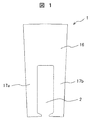
- FIG. 1 shows the shape of a stator core cut out for assembly of an insulation model.
- the core 1 is obtained by cutting a substantially cylindrical stator core into a fan shape having a central angle of 5 °, and is composed of a core back 16 and teeth 17a and 17b.
- One slot 2 is provided between the teeth 17a and 17b.
- the shape of the slot 2 is a substantially rectangular shape with a constant width, the width is 4.2 mm, and the parallel part depth is 12.1 mm.
- a punched electrical steel sheet equivalent to 35A300 JIS C 2552 is used.
- the electromagnetic steel sheets constituting the core 1 are laminated and fixed by welding the outer peripheral surface of each electromagnetic steel sheet.
- FIG. 2 is a perspective view showing the assembled insulation model.
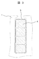
- FIG. 3 is a cross-sectional view showing the assembled insulation model.
- the insulation model is formed by stacking four copper conductors (coil wires) to form a simulated coil 4 (segment coil), and wrapping the central portion of the simulated coil 4 with slot insulating paper 5. It has a configuration inserted in the slot of the core 1.
- Each one of the simulated coils 4 is formed of a rectangular enamel insulated wire.
- the simulated coil 4 (segment coil) can also be called a bundle of electric wires.
- the length of the simulated coil 4 is 160 mm.
- the simulated coil 4 protrudes 33 mm evenly from both ends of the slot.
- a flat enamel insulated wire is obtained by coating a flat copper conductor (copper wire) with a polyimide insulating layer having a thickness of 0.05 mm.
- the cross-sectional dimensions of the flat enamel insulated wire are a short side of 2.89 mm, a long side of 3.42 mm, and a corner chamfer radius of 0.5 mm.
- the slot insulating paper 5 As the slot insulating paper 5, a three-layer laminated paper in which an aramid paper / PET / aramid paper having a thickness of 0.18 mm is bonded with a urethane-based adhesive is used.
- the length of the slot insulating paper 5 is 100 mm, and the slot insulating paper 5 protrudes by 3 mm from both ends of the slot.
- the first resin layer was formed by spray coating the following diluted solution on the surface of the flat enamel insulated wire.
- the diluting solution is obtained by dissolving, in acetone, a material obtained by mixing 90 parts by mass of an acid anhydride type curing agent and 2 parts by mass of an imitazole type curing accelerator with respect to 100 parts by mass of a phenol novolac type epoxy resin which is a polyfunctional epoxy resin. This was produced.
- the simulated coil 4 of the embodiment is obtained by forming the first resin layer on the surface of the flat enamel insulated wire.
- the coating thickness of the first resin layer was about 0.05 mm.
- a second resin layer was formed and subjected to a thermosetting treatment.
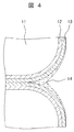
- FIG. 4 is a cross-sectional view showing a part of the simulation coil of the example.
- the copper conductor 11 is covered with a polyimide insulating layer 12 and the outside thereof is further covered with a first resin layer 13.
- the adjacent two copper conductors 11 are covered with the second resin layer 14 in the periphery.
- the second resin layer 14 is applied to the gap formed between the two adjacent copper conductors 11.
- the second resin layer 14 is provided at least at the corner (corner) of the two adjacent copper conductors 11.
- the first resin layer 13 covering each of the two copper conductors 11 is in contact but has a boundary.
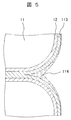
- FIG. 5 is a cross-sectional view showing a part of the simulated coil of the example after the thermosetting treatment.
- the first resin layer 13 in FIG. 4 is changed to the first cured resin layer 113, and the second resin layer 14 is changed to the second cured resin layer 114.
- the first resin layer 13 between the two copper conductors 11 is melted, thermoset, and integrated. For this reason, the boundary shown in FIG. 4 disappears.
- the second cured resin layer 114 is provided at least at the corner (corner) of the two adjacent copper conductors 11.
- stator By using the above-described stator, it is possible to manufacture a rotating electrical machine that can withstand a high driving voltage without increasing the thickness of the slot insulating paper.
- Example 1 a resin composition prepared by mixing 80 parts by mass of an acid anhydride-based curing agent and 1 part by mass of an imidazole-based curing accelerator with respect to 100 parts by mass of a bisphenol A type epoxy resin.
- the second resin layer was formed by pouring into the gap of the constituent material in the slot. Thereafter, it was thermoset to fix the constituent materials in the slots.
- Example 2 a resin composition prepared by mixing 2 parts by mass of a peroxide-based curing agent having an hour-and-half temperature of 125 ° C. with respect to 100 parts by mass of an unsaturated polyester resin is the same as in Example 1. Then, the second resin layer was formed by pouring into the gap of the constituent material in the slot. Thereafter, it was thermoset to fix the constituent materials in the slots.
- the first resin layer is not formed, and the structure shown in FIGS. 2 and 3 is used.
- the second resin layer was formed by pouring into the substrate. Thereafter, it was thermoset to obtain an insulation model corresponding to the prior art.
- thermosetting in the examples and comparative examples were 160 ° C. ⁇ 1 hour. By this thermosetting treatment, the first resin layer and the second resin layer were simultaneously cured.
- Table 1 shows the configuration of the insulation model in the examples and comparative examples.
- the resin material constituting the first resin layer is referred to as a first resin
- the resin material constituting the second resin layer is referred to as a second resin.
- heat treatment was performed at 220 ° C. ⁇ 960 hours, and the partial discharge start voltage before and after the thermal degradation treatment was measured.
- Table 2 shows the measurement results of the partial discharge start voltage.
- the numerical values in the table are the average values of the partial discharge starting voltages between adjacent coil wires (3 sets / insulation model).
- the partial discharge start voltage was a voltage at which the discharge charge amount reached 100 pC, and the applied voltage frequency was 50 Hz.
- Example 1 what was 1.95 before heat deterioration was 1.97 after heat deterioration.
- Example 2 what was 2.02 before heat deterioration was 1.85 after heat deterioration.
- FIG. 6 is a perspective view schematically showing the state of the resin crack in the comparative example.
- the copper conductor 11 is covered with the polyimide insulating layer 12, and the second cured resin layer 114 is formed in the gap formed between the two adjacent copper conductors 11. Has been. A large resin crack 15 is generated in the second cured resin layer 114.
- the partial discharge start voltage after thermal degradation in the comparative example is almost equal to the partial discharge start voltage between lines measured by a model (back-to-back model) in which two flat enamel insulated wires of a simulated coil are simply combined. Therefore, when the resin crack 15 generated in the comparative example reaches the polyimide insulating layer 12 of the simulated coil, it can be inferred that a gap connecting the adjacent simulated coils is formed, and the state is equivalent to the back-to-back model.
- Example 1 the vicinity of the interface between the first cured resin layer and the second cured resin layer in Examples 1 and 2 was investigated in detail. As a result, in Example 1, it turned out that the mixed layer of both resin is formed between the 1st cured resin layer and the 2nd cured resin layer.
- FIG. 7 shows a cross section including the mixed layer.
- a mixed layer 116 is formed between the first cured resin layer 113 and the second cured resin layer 114.
- the mixed layer 116 is a region where the components of the first cured resin layer 113 and the components of the second cured resin layer 114 are mixed.
- both the first resin and the second resin are epoxy resins, they are easy to mix.
- the mixed layer 116 has a component close to the component of the first cured resin layer 113 at a portion in contact with the first cured resin layer 113, and the second cured resin at a portion in contact with the second cured resin layer 114. It has a component close to that of the layer 114. In other words, the mixed layer 116 has a concentration gradient. For this reason, the physical properties of the mixed layer 116 change smoothly. Thereby, the progress of cracks in the second cured resin layer 114 is further suppressed, and it is considered that the partial discharge start voltage after thermal degradation is maintained higher than that in the second embodiment.
- a trifunctional phenol novolac type epoxy resin was used as the first resin, but a polyfunctional epoxy resin such as a cresol novolac type epoxy resin, a glycidyl amine type epoxy resin, a glycidyl ether type epoxy resin or the like was used alone or It is also possible to apply by mixing. Moreover, the resin composition which mixed bifunctional epoxy resin, such as a bisphenol A type
- an acid anhydride curing agent is used in the present invention, but a curing agent generally used as an epoxy resin curing agent such as amine, polyamide, and dicyandiamide is applicable. It is important to select a curing agent that can impart high heat resistance to the cured epoxy resin.
- a flat enamel insulated wire was separately coated with a first resin to produce an insulation model.
- the actual stator is manufactured according to the present invention, it is not a good solution in terms of manufacturing cost to coat the first resin on the coil in the same manner as in the embodiment.
- a method for forming a stator coil using a flat enamel insulated wire pre-coated with a resin for forming the first resin layer is desirable as a method for manufacturing the stator.
- FIG. 8 is a flowchart showing an example of a manufacturing method of an actual stator.
- a segment coil (coil wire) used for the stator is formed (S101), and the first fixed varnish containing the first resin is coated on the segment coil (one coil wire). (S102). Then, the slot insulating paper is inserted into the slot, and the segment coil (coil wire) is inserted into the space inside the slot insulating paper in the slot (S103). Thereafter, the segment coil is bent (S104), and the segment coil is welded (S105). Thereafter, a second fixed varnish containing a second resin is applied or impregnated into the segment coil (S106), and a thermosetting process is performed (S107).
- FIG. 9 is a cross-sectional view showing a rotating electrical machine equipped with the stator of the present invention.
- the rotating electrical machine 200 includes a rotor 210, a stator 220, and a housing 251.
- a stator 220 is fixed on the inner peripheral side of the housing 251.
- a rotor 210 is rotatably installed on the inner peripheral side of the stator 220.
- the housing 251 is formed into a cylindrical shape by cutting of an iron-based material such as carbon steel, casting of cast steel or aluminum alloy, or press working, and constitutes an outer casing of the electric motor.
- the housing 251 is also called a frame or a frame.
- a liquid cooling jacket 230 is fixed to the outer peripheral side of the housing 251. Between the inner peripheral wall of the liquid cooling jacket 230 and the outer peripheral wall of the housing 251, a refrigerant passage 253 for a liquid refrigerant RF such as oil is provided. The refrigerant passage 253 is formed so as not to leak.
- the liquid cooling jacket 230 houses the bearings 244 and 245 and is also called a bearing bracket.
- the refrigerant RF is configured such that liquid accumulated in the refrigerant (oil) storage space 250 passes through the refrigerant passage 253 and flows out from the refrigerant outlets 254 and 255 toward the stator 220 to cool the stator 220.
- the stator 220 includes a stator core 232.
- the stator core 232 is a laminate of thin silicon steel plates.
- the stator core 232 is provided with a stator coil (reference numeral 260 in FIG. 10 described later).
- the stator coil is wound around a plurality of slots provided in the inner peripheral portion of the stator core 232. Heat generated from the stator coil is transferred to the liquid cooling jacket 230 via the stator core 232 and is radiated by the refrigerant RF flowing through the liquid cooling jacket 230.
- the rotor 210 is composed of a rotor core 212 and a shaft 213.
- the rotor core 212 has a configuration in which thin plates of silicon steel plates are laminated.
- the shaft 213 is fixed to the center of the rotor core 212.
- the shaft 213 is rotatably supported by bearings 244 and 245 attached to the liquid cooling jacket 230 and rotates at a predetermined position in the stator 220.
- the rotor 210 has a permanent magnet 218. The rotor 210 rotates by the magnetic action of the stator 220 that generates a rotating magnetic field.
- a neutral point connection conductor 240 is drawn out from one coil end 261 of the stator coil.
- the coil end 262 is welded.
- the liquid cooling jacket 230 includes an engine case, a transmission case, and the like.
- Rotating electric machine 200 is a three-phase synchronous motor with a built-in permanent magnet.
- the rotating electrical machine 200 operates as an electric motor that rotates the rotor 210 by supplying a three-phase alternating current to a stator coil wound around the stator core 232. Further, when the rotating electrical machine 200 is driven by the engine, it operates as a generator and outputs three-phase AC generated power. That is, the rotating electrical machine 200 has both a function as an electric motor that generates rotational torque based on electric energy and a function as a generator that generates electric power based on mechanical energy. The above functions can be selectively used.
- FIG. 10 is a perspective view showing a state before the stator is inserted into the housing.
- the housing 251 is formed into a cylindrical shape by drawing a steel plate (such as a high-tensile steel plate) having a thickness of about 2 to 5 mm.
- the housing 251 is provided with a plurality of flanges 315 for fixing the liquid cooling jacket.
- the plurality of flanges 315 are provided radially outward at the peripheral edge of one end surface of the cylindrical housing 251.
- the stator 220 includes a stator coil 260 and a cylindrical stator core 232 to which the stator coil 260 is attached.
- the stator core 232 is formed by laminating thin plates (thickness of about 0.05 to 1.0 mm) of silicon steel plates (electromagnetic steel plates).
- a welded portion 270 is provided on the outer peripheral portion of the cylindrical stator core 232 in parallel with the axial direction of the stator core 232. Since the welded portion 270 is formed in a semicircular weld groove provided in advance on the outer peripheral portion of the stator core 232, the welded portion 270 does not protrude outward in the radial direction of the stator core 232.
- the welded portion 270 is formed by TIG welding or laser welding.
- the stator core 232 has a core back 342 and teeth 395.
- the stator coil 260 has a total of six coils (U 1, U 2, V 1, V 2, W 1, W 2) attached in close contact with the stator core 232.
- the six coils constituting the stator coil 260 are arranged at appropriate intervals by slots.
- One coil end 340 of the stator coil 260 has AC terminals 391 (U), 392 (V), and 393 (W), which are coil conductors for input and output of the respective stator coils 260 of the UVW three-phase, A sex point connection conductor 240 is drawn out.
- the stator 220 is supplied with AC power by being connected to a power converter (not shown) through the AC terminals 391 (U), 392 (V), and 393 (W). Yes.
- the stator coil 260 has a structure in which the outer periphery of the conductor is covered with an insulating film, and electrical insulation is maintained. In addition to the insulating coating, the reliability can be further improved by maintaining the withstand voltage with the insulating paper 380.
- the insulating paper 380 contributes to maintaining a necessary withstand voltage even if the insulating coating is damaged or deteriorated.
- the stator core 232 is fitted and fixed inside the housing 251 by shrink fitting.
- a specific method of assembly for example, first, a housing 251 that has been heated in advance and expanded in inner diameter by thermal expansion is fitted into the stator core 232. Next, by cooling the housing 251 and shrinking the inner diameter, the outer periphery of the stator core 232 is tightened by the heat shrinkage.
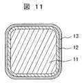
- FIG. 11 is a schematic cross-sectional view showing an example of the coiled electric wire of the present invention.
- the coil electric wire is obtained by providing a polyimide insulating layer 12 on the surface of a substantially rectangular copper conductor 11 and applying a first resin layer 13 on the outside thereof.
- the corner of the copper conductor 11 usually has a curvature.
- the coil wire is a component for that purpose.
- the coil electric wire is obtained by applying a non-cured first resin (resin composition) to the surface of a flat enamel insulated wire.
- a coil electric wire as shown in this figure is prepared in advance, cut into a required length, and used to perform a part of the process of manufacturing the stator externally, and the first resin is applied immediately before assembly. The process can be omitted.
Landscapes
- Engineering & Computer Science (AREA)
- Power Engineering (AREA)
- Manufacturing & Machinery (AREA)
- Insulation, Fastening Of Motor, Generator Windings (AREA)
- Manufacture Of Motors, Generators (AREA)
Abstract
固定子コイルの温度上昇及び固定子コイルへの高電圧印加において、固着樹脂の熱劣化を防止し、固定子の絶縁信頼性を向上する。 コアバック及びティースを有するコアと、絶縁層で被覆された導体、及び絶縁層の外表面を被覆する第1の樹脂を含む電線と、を備えた固定子であって、電線の束であるセグメントコイルの外表面のうち隣り合う電線の少なくとも角部には、第2の樹脂が設けられている。
Description
本発明は、固定子、回転電機、固定子の製造方法、回転電機の製造方法、及び固定子に用いるコイル電線に関する。
産業や生活に密着した回転電機は、現代の社会を支える基盤機器である。特に、地球環境保護の観点から、ハイブリッド自動車や電気自動車が普及しつつある。これらの自動車においては、設置スペースの確保および軽量化による燃費向上の観点から、動力源のモータの小型・軽量化が要求される。
ハイブリッド自動車や電気自動車に用いる動力モータの固定子スロットの絶縁部は、固定子コア/コイル間および異相コイル間に挿入される絶縁紙(スロットライナ)と、それらの空隙を充填しコイルおよび絶縁紙をコアに固定する固着ワニスと、で構成されている(例えば、特許文献1参照)。
動力モータを小型化するためには、駆動電圧を高くする手段又はコイル電流密度を高くする手段が考えられる。しかしながら、いずれの手段も、固定子内コイルの絶縁部における負荷の増大につながるため、小型化に対応するための絶縁構造を設計する必要がある。
駆動電圧を高くする手段を用いる場合において従来技術の延長線上で対処するには、絶縁紙の厚さを増大させ、作用電圧に対応した絶縁距離を確保することになる。しかしながら、この手法では、スロット内のコイル占積率の低下を招き、コイル電流が低下する。この点を補うには、コイル電流密度を高くする必要があり、コイルの温度上昇が避けられない。
もう一つのコイル電流密度を高くする手段を用いる場合においては、上述の場合と同様に、コイルの温度上昇を伴うため、ハイブリッド自動車や電気自動車に用いる動力モータを小型化する際には障害となる。
従来の固定子の絶縁部においては、固着ワニスとしては、モータの運転により温度が上昇しても固着力が低下しない熱硬化性樹脂が用いられる。スロット内の構成部材を強固に固着させるためには、構成部材間の空隙への浸透性を考慮して、粘度の低い樹脂が用いられる。
一般的に、粘度の低い熱硬化性樹脂の耐熱性を改善することは困難であり、コイル電流密度アップに伴うコイルの温度上昇は、スロットの絶縁部における固着樹脂の熱劣化に伴う絶縁信頼性の低下の原因となる。
本発明は、固定子コイルの温度上昇及び固定子コイルへの高電圧印加において、固着樹脂の熱劣化を防止し、固定子の絶縁信頼性を向上することを目的とする。
本発明の固定子は、コアバック及びティースを有するコアと、絶縁層で被覆された導体、及び絶縁層の外表面を被覆する第1の樹脂を含む電線と、を備え、電線の束であるセグメントコイルの外表面のうち隣り合う電線の少なくとも角部には、第2の樹脂が設けられている。
本発明によれば、固定子コイルの温度上昇及び固定子コイルへの高電圧印加において、固着樹脂の熱劣化により発生する樹脂クラックを防止し、樹脂クラックにより引き起こされる部分放電開始電圧の低下を防止することができ、固定子の絶縁信頼性を向上することができる。
本発明は、固定子、回転電機、固定子の製造方法、回転電機の製造方法、及び固定子に用いるコイル電線に関する。回転電機は、電動車両等に適用される。
以下、外径245mm、内径200mm、スロット数72、コア積厚94mmの固定子コアから切り出したコアに模擬コイル及びスロット絶縁紙を組み込み、それぞれの樹脂構成でスロット内構成材を固着した絶縁モデルについて部分放電開始電圧の測定を行った結果を用いて、本発明の実施形態について説明する。後述の実施例及び比較例は、回転電機の固定子の部分モデルであるが、下記の説明から自明のように、実機の回転電機の固定子と等価である。
図1は、絶縁モデル組立用に切り出した固定子コアの形状を示したものである。
本図においては、コア1は、略円筒形状の固定子コアを中心角5°の扇形に切断したものであり、コアバック16と、ティース17a、17bと、で構成されている。ティース17a、17bの間には、一つのスロット2が設けられている。
スロット2の形状は、幅一定の略矩形状であり、その幅は4.2mm、平行部深さは12.1mmである。コア1には、35A300相当(JIS C 2552)の打ち抜き電磁鋼板が用いられている。コア1を構成する電磁鋼板は、積層され、各々の電磁鋼板の外周部の表面を溶接することにより固定されている。
図2は、組み立てた絶縁モデルを示す斜視図である。また、図3は、組み立てた絶縁モデルを示す断面図である。
これらの図に示すように、絶縁モデルは、4本の銅導体(コイル電線)を積み重ねることにより模擬コイル4(セグメントコイル)とし、模擬コイル4の中央部をスロット絶縁紙5で包み込み、これらをコア1のスロットに挿入した構成を有する。一本一本の模擬コイル4は、平角エナメル絶縁線で形成されている。なお、模擬コイル4(セグメントコイル)は、電線の束と呼ぶこともできる。
模擬コイル4の長さは、160mmとしている。模擬コイル4は、スロットの両端部から均等に33mmはみ出させている。平角エナメル絶縁線は、平角の銅導体(銅線)の表面に厚さ0.05mmのポリイミド絶縁層が被覆されたものである。平角エナメル絶縁線の断面寸法は、短辺2.89mm、長辺3.42mm、コーナー面取り半径0.5mmである。
スロット絶縁紙5としては、厚さ0.18mmのアラミド紙/PET/アラミド紙がウレタン系接着剤で接着された3層ラミネート紙を用いている。スロット絶縁紙5の長さは100mmとし、スロット絶縁紙5は、スロットの両端部から3mmずつはみ出させている。
上記の絶縁モデルを共通条件として、実施例においては、平角エナメル絶縁線の表面に、次の希釈液をスプレーコーティングすることにより、第1の樹脂層を形成した。
希釈液は、多官能エポキシ樹脂であるフェノールノボラック型エポキシ樹脂100質量部に対して、酸無水物系の硬化剤90質量部、イミタゾール系硬化促進剤2質量部を混合した材料をアセトンで溶解することにより作製した。
よって、実施例の模擬コイル4は、平角エナメル絶縁線の表面に第1の樹脂層を形成したものである。ここで、第1の樹脂層の被覆厚さは、約0.05mmとした。
さらに、スロット内の構成材を完全に固着させるために、第2の樹脂層を形成し、熱硬化処理を施した。
図4は、実施例の模擬コイルの一部を示す断面図である。
本図において、熱硬化処理を施す前の状態を示している。銅導体11は、ポリイミド絶縁層12で被覆され、その外側を更に第1の樹脂層13で覆われている。そして、隣接する2本の銅導体11は、その周囲を第2の樹脂層14で覆われている。言い換えると、隣接する2本の銅導体11の間に形成された空隙には、第2の樹脂層14が塗布されている。第2の樹脂層14は、隣り合う2本の銅導体11の少なくとも角部(コーナー部)に設けられている。2本の銅導体11のそれぞれを覆う第1の樹脂層13は、接しているが、境界を有している。
図5は、熱硬化処理を施した後における実施例の模擬コイルの一部を示す断面図である。
本図においては、図4の第1の樹脂層13が第1の硬化樹脂層113に、第2の樹脂層14が第2の硬化樹脂層114に変化している。図5においては、2本の銅導体11の間にある第1の樹脂層13は、溶融し、熱硬化し、一体化している。このため、図4に示す境界は消えている。第2の硬化樹脂層114は、隣り合う2本の銅導体11の少なくとも角部(コーナー部)に設けられている。
上述の固定子を用いることにより、スロット絶縁紙の厚さを増大させることなく、高い駆動電圧に耐え得る回転電機を製造することができる。
つぎに、第2の樹脂層を形成するために用いた樹脂組成物について説明する。
実施例1においては、ビスフェノールA型エポキシ樹脂100質量部に対し、酸無水物系の硬化剤80質量部と、イミタゾール系硬化促進剤1質量部と、を混合して作製した樹脂組成物を、スロット内の構成材の空隙に流し込むことにより、第2の樹脂層を形成した。その後、熱硬化させ、スロット内の構成材を固着させた。
実施例2においては、不飽和ポリエステル樹脂100質量部に対し、1時間半減温度が125℃の過酸化物系硬化剤2質量部を混合して作製した樹脂組成物を、実施例1と同様に、スロット内の構成材の空隙に流し込むことにより、第2の樹脂層を形成した。その後、熱硬化させ、スロット内の構成材を固着させた。
(比較例)
比較例においては、第1の樹脂層を形成していない状態で、図2及び3に示す構成とし、実施例1の第2の樹脂層に用いた樹脂組成物をスロット内の構成材の空隙に流し込むことにより、第2の樹脂層を形成した。その後、熱硬化させ、従来技術に相当する絶縁モデルとした。
比較例においては、第1の樹脂層を形成していない状態で、図2及び3に示す構成とし、実施例1の第2の樹脂層に用いた樹脂組成物をスロット内の構成材の空隙に流し込むことにより、第2の樹脂層を形成した。その後、熱硬化させ、従来技術に相当する絶縁モデルとした。
実施例及び比較例における熱硬化の条件は、160℃×1時間とした。この熱硬化処理により、第1の樹脂層及び第2の樹脂層が同時に硬化された。
表1は、実施例及び比較例における絶縁モデルの構成を示したものである。ここで、第1の樹脂層を構成する樹脂材料を第1の樹脂、第2の樹脂層を構成する樹脂材料を第2の樹脂と呼ぶ。
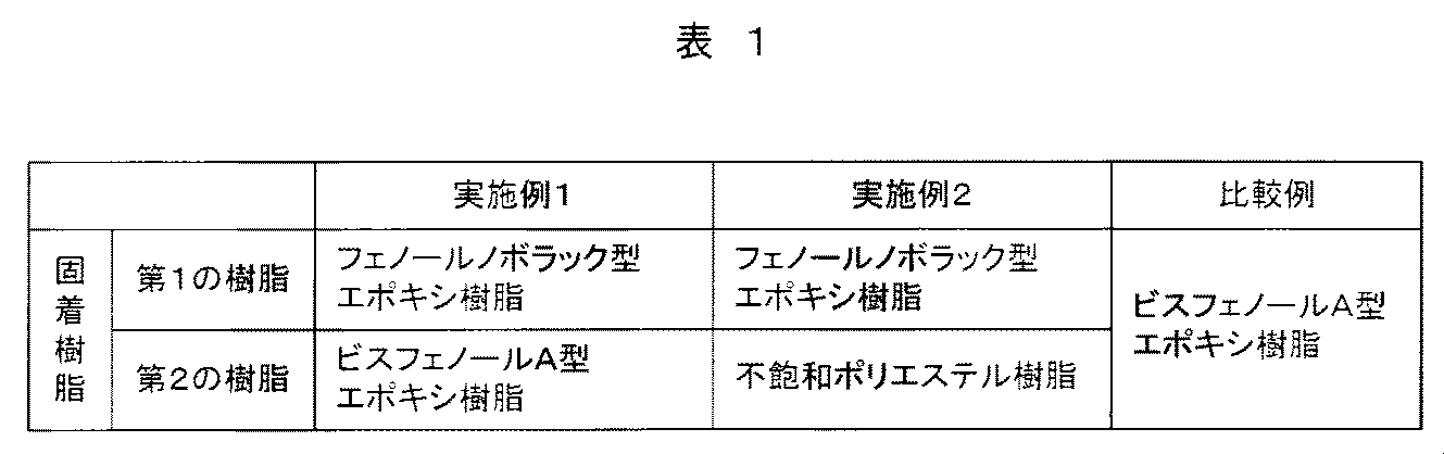
つぎに、実施例及び比較例として製作した絶縁モデルの固着樹脂の熱劣化について説明する。
固着樹脂(樹脂硬化物)の熱劣化を目的として、220℃×960時間で熱処理し、熱劣化処理前後の部分放電開始電圧の測定を行った。
表2は、部分放電開始電圧の測定結果を示したものである。表中の数値は、各隣接コイル電線間(3組み/絶縁モデル)の部分放電開始電圧の平均値で示したものである。部分放電開始電圧は、放電電荷量が100pCに達した電圧とし、印加電圧周波数は、50Hzとした。
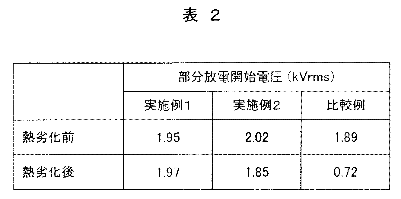
表2から、実施例及び比較例とも、熱劣化前には、同様の部分放電開始電圧を示す。具体的には、1.89~2.02である。
実施例1においては、熱劣化前に1.95であったものが、熱劣化後においては1.97となっている。
実施例2においては、熱劣化前に2.02であったものが、熱劣化後においては1.85となっている。
これに対して、比較例においては、熱劣化前に1.89であったものが、熱劣化後においては0.72にまで低下している。
よって、実施例1及び2においては、熱劣化後でも部分放電開始電圧の低下が発生せず、本発明の効果が確認できる。しかし、比較例においては、熱劣化後に部分放電開始電圧が大きく低下することがわかる。
ここで、熱劣化後の絶縁モデルを解体し、固着樹脂の状態を観察したところ、比較例では、樹脂クラックが発生していることがわかった。
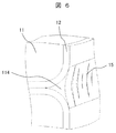
図6は、比較例における樹脂クラックの状態を模式的に示す斜視図である。
本図に示すように、比較例の場合、銅導体11は、ポリイミド絶縁層12で被覆され、隣接する2本の銅導体11の間に形成された空隙に第2の硬化樹脂層114が形成されている。第2の硬化樹脂層114には、大きな樹脂クラック15が発生している。
比較例における熱劣化後の部分放電開始電圧は、模擬コイルの平角エナメル絶縁線2本の平面を単純に合わせたモデル(背合わせモデル)で測定される線間の部分放電開始電圧とほぼ等しい。よって、比較例で発生した樹脂クラック15が模擬コイルのポリイミド絶縁層12に到達した場合、隣接模擬コイルを連結する空隙が形成され、背合わせモデルと同等の状態となったことが推察できる。
このことから、更に熱劣化が進行した場合、模擬コイルのポリイミド絶縁層12が劣化し、早期に絶縁破壊に至ることが予想される。
同様に、熱劣化後の実施例1及び2の絶縁モデルを解体調査したところ、比較例と同様に、第2の樹脂層にはクラックが発生したが、その程度は軽微であり、第1の樹脂層との界面付近でクラック進展が停止している様子が確認され、固着樹脂として耐熱性の高い多官能エポキシ樹脂を第1の樹脂層として模擬コイルコーナ部に配置した効果が確認できた。
ところで、実施例1及び2では、第2の樹脂層の形成に用いた材料が異なっている。このため、表2に示すように、熱劣化後の部分放電開始電圧には差が生じていないものの、形態的に異なってくる可能性がある。
そこで、実施例1及び2の第1の硬化樹脂層と第2の硬化樹脂層との界面近傍を詳細に調査した。その結果、実施例1においては、第1の硬化樹脂層と第2の硬化樹脂層との間に両樹脂の混合層が形成されていることがわかった。
図7は、上記の混合層を含む断面を示したものである。
本図に示すように、実施例1においては、第1の硬化樹脂層113と第2の硬化樹脂層114との間に混合層116が形成されている。混合層116は、第1の硬化樹脂層113の成分と第2の硬化樹脂層114の成分とが混ざり合った領域である。実施例1の場合、第1の樹脂及び第2の樹脂がともにエポキシ樹脂であるため、混合しやすい。混合層116は、第1の硬化樹脂層113に接する部分においては第1の硬化樹脂層113の成分に近い成分を有し、第2の硬化樹脂層114に接する部分においては第2の硬化樹脂層114の成分に近い成分を有する。言い換えると、混合層116は、濃度勾配を有する。このため、混合層116においては、物性が滑らかに変化している。これにより、第2の硬化樹脂層114におけるクラックの進展がより抑えられ、実施例2に比べ、熱劣化後の部分放電開始電圧が高く維持されるものと考えられる。
実施例においては、第1の樹脂として、三官能のフェノールノボラック型エポキシ樹脂を用いたが、クレゾールノボラック型エポキシ樹脂、グリシジルアミン系エポキシ樹脂、グリシジルエーテル系エポキシ樹脂等の多官能エポキシ樹脂を単体あるいは混合して適用することも可能である。また、ビスフェノールA型等の二官能エポキシ樹脂と上記の多官能エポキシ樹脂とを混合した樹脂組成物も適用可能である。
第1の樹脂の硬化剤として、本発明では、酸無水物系硬化剤を用いたが、アミン系、ポリアミド系、ジシアンジアミド等のエポキシ樹脂硬化剤として一般に用いられる硬化剤が適用可能であるが、硬化エポキシ樹脂に高耐熱性を付与することができる硬化剤を選定することが肝要である。
ところで、実施例では、平角エナメル絶縁線に、別途、第1の樹脂を被覆して絶縁モデルを製作した。しかし、実機の固定子を本発明により製作する場合、実施例と同様な手法で第1の樹脂をコイルに被覆するのは、製造コストの面で得策とは言えない。このため、第1の樹脂層を形成する樹脂があらかじめ塗布された平角エナメル絶縁線を用い、固定子コイルを形成する方法が固定子の製造方法として望ましい。
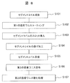
図8は、実機の固定子の製造方法の例を示すフロー図である。
本図に示すように、固定子に用いるセグメントコイル(コイル電線)を成形し(S101)、第1の樹脂を含む第1の固着ワニスをセグメントコイル(1本1本のコイル電線)にコーティングする(S102)。そして、スロット絶縁紙をスロットに挿入し、スロット内のスロット絶縁紙の内側の空間にセグメントコイル(コイル電線)を挿入する(S103)。その後、セグメントコイルの曲げ加工を行い(S104)、セグメントコイルを溶接する(S105)。その後、第2の樹脂を含む第2の固着ワニスをセグメントコイルに塗布し、又は含浸し(S106)、熱硬化処理を行う(S107)。
以下、回転電機及び固定子の例について説明する。
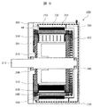
図9は、本発明の固定子を備えた回転電機を示す断面図である。
本図において、回転電機200は、回転子210と、固定子220と、ハウジング251と、を備えている。
ハウジング251の内周側には、固定子220が固定されている。固定子220の内周側には、回転子210が回転可能に設置されている。ハウジング251は、炭素鋼などの鉄系材料の切削、鋳鋼やアルミニウム合金の鋳造、又はプレス加工により、円筒状に成形されたものであり、電動機の外被を構成している。ハウジング251は、枠体又はフレームとも呼ばれている。
ハウジング251の外周側には、液冷ジャケット230が固定されている。液冷ジャケット230の内周壁とハウジング251の外周壁との間には、油などの液体の冷媒RFの冷媒通路253が設けられている。この冷媒通路253は、液漏れしないように形成されている。液冷ジャケット230は、軸受244、245を収納しており、軸受ブラケットとも呼ばれている。
冷媒RFは、冷媒(油)の貯蔵空間250に溜まった液体が冷媒通路253を通り、冷媒出口254、255から固定子220へ向けて流出し、固定子220を冷却するようになっている。
固定子220は、固定子鉄心232を含む。固定子鉄心232は、珪素鋼板の薄板が積層されたものである。固定子鉄心232には、固定子コイル(後述の図10における符号260)が設けられている。固定子コイルは、固定子鉄心232の内周部に多数個設けられているスロットに巻回されている。固定子コイルからの発熱は、固定子鉄心232を介して、液冷ジャケット230に伝熱され、液冷ジャケット230内を流通する冷媒RFにより放熱される。
回転子210は、回転子鉄心212とシャフト213とで構成されている。回転子鉄心212は、珪素鋼板の薄板が積層された構成を有している。シャフト213は、回転子鉄心212の中心に固定されている。シャフト213は、液冷ジャケット230に取り付けられた軸受244、245により回転自在に支持されており、固定子220内の所定の位置で回転する。また、回転子210は、永久磁石218を有している。回転子210は、回転磁界を発生する固定子220の磁気的作用により回転する。
固定子コイルにおける一方のコイルエンド261からは、中性点結線用導体240が引き出されている。コイルエンド262は、溶接されている。
なお、液冷ジャケット230は、エンジンのケースや変速機のケース等によって構成される。
回転電機200は、永久磁石内蔵型の三相同期モータである。回転電機200は、固定子鉄心232に巻回される固定子コイルに三相交流電流を供給することにより、回転子210を回転させる電動機として作動する。また、回転電機200は、エンジンによって駆動されると、発電機として作動して三相交流の発電電力を出力する。つまり、回転電機200は、電気エネルギーに基づいて回転トルクを発生する電動機としての機能と、機械エネルギーに基づいて発電を行う発電機としての機能との両方を有しており、自動車の走行状態によって上記機能を選択的に利用することができる。
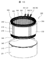
図10は、固定子をハウジングに挿入する前の状態を示す斜視図である。
本図においては、回転電機のハウジング251と固定子220とを示している。
ハウジング251は、厚さ2~5mm程度の鋼板(高張力鋼板など)を絞り加工により円筒形状に形成されている。ハウジング251には、液冷ジャケットを固定するための複数のフランジ315が設けられている。複数のフランジ315は、円筒状のハウジング251の一端面の周縁部に、径方向外方に向かって設けられている。
固定子220は、固定子コイル260と、この固定子コイル260が装着される円筒状の固定子鉄心232と、を有している。
固定子鉄心232は、珪素鋼板(電磁鋼板)の薄板(厚さ0.05~1.0mm程度)が積層されたものである。円筒状の固定子鉄心232の外周部には、固定子鉄心232の軸方向に平行に溶接部270が設けられている。溶接部270は、固定子鉄心232の外周部に予め設けられた半円状の溶接溝に形成されているため、溶接部270が固定子鉄心232の径方向外方に突出することはない。溶接部270は、TIG溶接やレーザー溶接などにより形成される。
固定子鉄心232は、コアバック342と、ティース395と、を有する。
固定子コイル260は、全体で6系統(U1、U2、V1、V2、W1、W2)のコイルが固定子鉄心232に密着して装着されている。そして、固定子コイル260を構成する6系統のコイルは、スロットによって相互に適正な間隔をもって配列されている。
固定子コイル260における一方のコイルエンド340には、UVW三相それぞれの固定子コイル260の入出力用のコイル導体である交流端子391(U)、392(V)、393(W)と、中性点結線用導体240と、が引き出されている。
なお、回転電機の組み立てにおける作業性向上のため、交流端子391(U)、392(V)、393(W)は、コイルエンド340から固定子鉄心232の軸方向の外方に突出するように配置されている。そして、固定子220には、この交流端子391(U)、392(V)、393(W)を介して図示しない電力変換装置に接続されることにより、交流電力が供給されるようになっている。
固定子コイル260は、導体の外周が絶縁被膜で覆われた構造とされ、電気的な絶縁性が維持されている。絶縁被膜に加えて、絶縁紙380により絶縁耐圧を維持すれば、更に信頼性を向上することができる。
絶縁紙380は、絶縁被膜が傷ついたり劣化したりしても、必要な絶縁耐圧の保持に寄与する。
図10に示すように、固定子鉄心232は、ハウジング251の内側に焼嵌めにより嵌合固定される。具体的な組み立て方としては、例えば、まず、固定子鉄心232に、予め加熱して熱膨張により内径を広げておいたハウジング251を嵌め込む。次に、ハウジング251を冷却して内径を収縮させることにより、その熱収縮により固定子鉄心232の外周部を締め付ける。
以下、固定子の部品であるコイル電線について説明する。
図11は、本発明のコイル電線の例を示す模式断面図である。
本図に示すように、コイル電線は、略矩形状の銅導体11の表面にポリイミド絶縁層12を設け、その外側に第1の樹脂層13を塗布したものである。銅導体11の角部は、通常、曲率を有している。
本図に示すコイル電線を作製し、熱硬化処理を施す前に、絶縁紙に包んで固定子コアのスロットに挿入し、スロット内の空隙に第2の樹脂を流し込み、その後、熱硬化処理を施すことにより、スロット内の構成材を固着させる。コイル電線は、そのための部品である。言い換えると、コイル電線は、平角エナメル絶縁線の表面に、硬化していない第1の樹脂(樹脂組成物)を塗布したものである。
本図に示すようなコイル電線をあらかじめ準備し、必要な長さに切断して用いることにより、固定子の作製における工程の一部を外部で行い、組み立ての直前に第1の樹脂を塗布する工程を省略することができる。
1:コア、2:スロット、4:模擬コイル、5:スロット絶縁紙、11:銅導体、12:ポリイミド絶縁層、13:第1の樹脂層、14:第2の樹脂層、15:樹脂クラック、113:第1の硬化樹脂層、114:第2の硬化樹脂層、116:混合層、200:回転電機、210:回転子、220:固定子。
Claims (11)
- コアバック及びティースを有するコアと、
絶縁層で被覆された導体、及び前記絶縁層の外表面を被覆する第1の樹脂を含む電線と、を備え、
前記電線の束であるセグメントコイルの外表面のうち隣り合う前記電線の少なくとも角部には、第2の樹脂が設けられている、固定子。 - 請求項1記載の固定子であって、
前記第1の樹脂は、多官能エポキシ樹脂であり、
前記第2の樹脂は、二官能エポキシ樹脂である、固定子。 - 請求項1記載の固定子であって、
前記第1の樹脂は、多官能エポキシ樹脂であり、
前記第2の樹脂は、不飽和ポリエステル樹脂である、固定子。 - 請求項1乃至3のいずれか一項に記載の固定子であって、
前記第1の樹脂と前記第2の樹脂との間には、前記第1の樹脂及び前記第2の樹脂を含む混合層が形成されている、固定子。 - 請求項1乃至4のいずれか一項に記載の固定子であって、
前記導体は、断面形状が略矩形状である、固定子。 - 請求項1乃至5のいずれか一項に記載の固定子と、回転子と、を備えた、回転電機。
- 請求項1乃至5のいずれか一項に記載の固定子を製造する方法であって、
前記ティースの間に形成されているスロットに前記電線を挿入する工程と、
隣り合う前記電線の少なくとも前記角部に前記第2の樹脂を設ける工程と、を含む、固定子の製造方法。 - 請求項6記載の回転電機を製造する方法であって、
前記固定子の前記コアを構成する前記ティースの間に形成されているスロットに前記電線を挿入する工程と、
隣り合う前記電線の少なくとも前記角部に前記第2の樹脂を設ける工程と、を含む、回転電機の製造方法。 - 固定子に用いる電線であって、
絶縁層で被覆された導体と、
前記絶縁層の外表面を被覆する第1の樹脂と、を含む、コイル電線。 - 請求項9記載のコイル電線であって、
前記導体は、断面形状が略矩形状である、コイル電線。 - 請求項9又は10に記載のコイル電線であって、
前記第1の樹脂は、多官能エポキシ樹脂である、コイル電線。
Priority Applications (1)
| Application Number | Priority Date | Filing Date | Title |
|---|---|---|---|
| CN201880010877.5A CN110383640A (zh) | 2017-03-01 | 2018-01-29 | 定子、旋转电机、定子的制造方法、旋转电机的制造方法以及定子中使用的线圈电线 |
Applications Claiming Priority (2)
| Application Number | Priority Date | Filing Date | Title |
|---|---|---|---|
| JP2017-038069 | 2017-03-01 | ||
| JP2017038069A JP6906329B2 (ja) | 2017-03-01 | 2017-03-01 | 固定子、回転電機、固定子の製造方法、及び回転電機の製造方法 |
Publications (1)
| Publication Number | Publication Date |
|---|---|
| WO2018159182A1 true WO2018159182A1 (ja) | 2018-09-07 |
Family
ID=63371233
Family Applications (1)
| Application Number | Title | Priority Date | Filing Date |
|---|---|---|---|
| PCT/JP2018/002633 Ceased WO2018159182A1 (ja) | 2017-03-01 | 2018-01-29 | 固定子、回転電機、固定子の製造方法、回転電機の製造方法、及び固定子に用いるコイル電線 |
Country Status (3)
| Country | Link |
|---|---|
| JP (1) | JP6906329B2 (ja) |
| CN (1) | CN110383640A (ja) |
| WO (1) | WO2018159182A1 (ja) |
Cited By (1)
| Publication number | Priority date | Publication date | Assignee | Title |
|---|---|---|---|---|
| US12592599B2 (en) * | 2021-05-17 | 2026-03-31 | Anhui Welling Auto Parts Co., Ltd. | Stator, electric motor, compressor and vehicle |
Families Citing this family (2)
| Publication number | Priority date | Publication date | Assignee | Title |
|---|---|---|---|---|
| JP2023011308A (ja) | 2021-07-12 | 2023-01-24 | 日立Astemo株式会社 | 回転電機および回転電機の固定子 |
| JP2026060584A (ja) * | 2024-09-27 | 2026-04-08 | 株式会社タムラ製作所 | ポリイミド、ポリイミドフィルム、多層配線基板、樹脂付き銅箔、コイル構造体、磁気デバイス及び絶縁電線 |
Citations (5)
| Publication number | Priority date | Publication date | Assignee | Title |
|---|---|---|---|---|
| JP2003134713A (ja) * | 2001-10-16 | 2003-05-09 | Honda Motor Co Ltd | 回転電機用ステータ |
| JP2005304223A (ja) * | 2004-04-14 | 2005-10-27 | Hitachi Cable Ltd | オルタネータ用ステータコイル |
| JP2007336725A (ja) * | 2006-06-16 | 2007-12-27 | Denso Corp | 回転電機の固定子 |
| JP2009021127A (ja) * | 2007-07-12 | 2009-01-29 | Mitsubishi Cable Ind Ltd | 集合導体 |
| JP2010263771A (ja) * | 2009-04-06 | 2010-11-18 | Denso Corp | ステータコイルのコイルエンド成形方法および成形装置 |
Family Cites Families (18)
| Publication number | Priority date | Publication date | Assignee | Title |
|---|---|---|---|---|
| JPH0817060B2 (ja) * | 1989-08-18 | 1996-02-21 | 株式会社日立製作所 | 電気絶縁線輪、回転電機及びその製造方法 |
| JP2004229460A (ja) * | 2003-01-27 | 2004-08-12 | Mitsubishi Electric Corp | 回転電機の固定子 |
| JP2008186724A (ja) * | 2007-01-30 | 2008-08-14 | Mitsubishi Cable Ind Ltd | 集合導体及びその製造方法 |
| JP2008312352A (ja) * | 2007-06-14 | 2008-12-25 | Honda Motor Co Ltd | 蛇行環状コイルの成形方法及び蛇行環状コイル |
| KR101560020B1 (ko) * | 2010-05-28 | 2015-10-15 | 주식회사 엘지화학 | 용융 가공 수지 성형품 |
| JP5839851B2 (ja) * | 2011-06-23 | 2016-01-06 | 日立オートモティブシステムズ株式会社 | 回転電機 |
| US20130125396A1 (en) * | 2011-11-18 | 2013-05-23 | Remy Technologies, L.L.C. | Wrapped wire for electric machine |
| JP2013109874A (ja) * | 2011-11-18 | 2013-06-06 | Hitachi Cable Ltd | 絶縁電線 |
| JP5486646B2 (ja) * | 2012-07-20 | 2014-05-07 | 株式会社デンソー | 絶縁電線 |
| CN202997722U (zh) * | 2012-12-19 | 2013-06-12 | 南车株洲电机有限公司 | 一种牵引电机及其定子 |
| US9928935B2 (en) * | 2013-05-31 | 2018-03-27 | General Electric Company | Electrical insulation system |
| FR3020521B1 (fr) * | 2014-04-29 | 2016-06-03 | Nicolas Langlard | Stator de machine electrique tournante muni d'un bobinage optimise |
| JP6156250B2 (ja) * | 2014-05-08 | 2017-07-05 | 株式会社デンソー | 回転電機の固定子及びその固定子を備えた回転電機 |
| JP6016846B2 (ja) * | 2014-06-03 | 2016-10-26 | 古河電気工業株式会社 | 絶縁ワイヤおよびその製造方法 |
| JP6354552B2 (ja) * | 2014-12-02 | 2018-07-11 | トヨタ自動車株式会社 | コイルの形成方法 |
| JP2016132246A (ja) * | 2015-01-22 | 2016-07-25 | オムロン株式会社 | 接合構造体の製造方法および接合構造体 |
| JP6028267B2 (ja) * | 2015-03-05 | 2016-11-16 | 株式会社明電舎 | 回転電機のコイル |
| CN106451869A (zh) * | 2016-11-30 | 2017-02-22 | 天津市松正电动汽车技术股份有限公司 | 一种扁线电机定子槽绝缘结构及其制作工艺 |
-
2017
- 2017-03-01 JP JP2017038069A patent/JP6906329B2/ja active Active
-
2018
- 2018-01-29 WO PCT/JP2018/002633 patent/WO2018159182A1/ja not_active Ceased
- 2018-01-29 CN CN201880010877.5A patent/CN110383640A/zh active Pending
Patent Citations (5)
| Publication number | Priority date | Publication date | Assignee | Title |
|---|---|---|---|---|
| JP2003134713A (ja) * | 2001-10-16 | 2003-05-09 | Honda Motor Co Ltd | 回転電機用ステータ |
| JP2005304223A (ja) * | 2004-04-14 | 2005-10-27 | Hitachi Cable Ltd | オルタネータ用ステータコイル |
| JP2007336725A (ja) * | 2006-06-16 | 2007-12-27 | Denso Corp | 回転電機の固定子 |
| JP2009021127A (ja) * | 2007-07-12 | 2009-01-29 | Mitsubishi Cable Ind Ltd | 集合導体 |
| JP2010263771A (ja) * | 2009-04-06 | 2010-11-18 | Denso Corp | ステータコイルのコイルエンド成形方法および成形装置 |
Cited By (1)
| Publication number | Priority date | Publication date | Assignee | Title |
|---|---|---|---|---|
| US12592599B2 (en) * | 2021-05-17 | 2026-03-31 | Anhui Welling Auto Parts Co., Ltd. | Stator, electric motor, compressor and vehicle |
Also Published As
| Publication number | Publication date |
|---|---|
| JP6906329B2 (ja) | 2021-07-21 |
| JP2018148600A (ja) | 2018-09-20 |
| CN110383640A (zh) | 2019-10-25 |
Similar Documents
| Publication | Publication Date | Title |
|---|---|---|
| JP5480106B2 (ja) | 回転電機 | |
| RU2638165C1 (ru) | Статор вращающейся электрической машины | |
| JP6402257B2 (ja) | 固定子コイル、これを備えた固定子、およびこれを備えた回転電機 | |
| US9647502B2 (en) | Stator and rotating electric machine | |
| US8772988B2 (en) | Stator structure for electric machine | |
| CN109478814B (zh) | 旋转电机的定子和旋转电机 | |
| JP4665454B2 (ja) | モータ | |
| US20170256997A1 (en) | Stator of Rotary Electric Machine and Rotary Electric Machine Equipped with the Same | |
| WO2020071037A1 (ja) | 回転電機 | |
| JP6906329B2 (ja) | 固定子、回転電機、固定子の製造方法、及び回転電機の製造方法 | |
| CN111492566A (zh) | 定子的制造方法 | |
| JPWO2017038326A1 (ja) | 回転子、これを備えた回転電機、及び回転子の製造方法 | |
| JP2004336883A (ja) | 車両用交流発電機 | |
| JP7208057B2 (ja) | 回転電機および車両 | |
| JP7044871B2 (ja) | 回転電機および回転電機の製造方法 | |
| JP2019122183A (ja) | 回転電機の固定子および回転電機 | |
| WO2025099993A1 (ja) | 回転電機の固定子 | |
| JP5988840B2 (ja) | 回転電機の固定子 | |
| JP2014082935A (ja) | 回転電機の固定子、およびこれを備えた回転電機 | |
| JP7460571B2 (ja) | 固定子及びこれを有する回転電機 | |
| JP7150171B2 (ja) | 回転電機の固定子、端子台及び回転電機 | |
| JP7620490B2 (ja) | 回転電機 | |
| JP6078305B2 (ja) | 回転電機の固定子 | |
| JP2023150105A (ja) | ステータ | |
| WO2025144294A1 (en) | An electric machine |
Legal Events
| Date | Code | Title | Description |
|---|---|---|---|
| 121 | Ep: the epo has been informed by wipo that ep was designated in this application |
Ref document number: 18760753 Country of ref document: EP Kind code of ref document: A1 |
|
| NENP | Non-entry into the national phase |
Ref country code: DE |
|
| 122 | Ep: pct application non-entry in european phase |
Ref document number: 18760753 Country of ref document: EP Kind code of ref document: A1 |