WO2018159094A1 - 対象物移動装置 - Google Patents
対象物移動装置 Download PDFInfo
- Publication number
- WO2018159094A1 WO2018159094A1 PCT/JP2017/047268 JP2017047268W WO2018159094A1 WO 2018159094 A1 WO2018159094 A1 WO 2018159094A1 JP 2017047268 W JP2017047268 W JP 2017047268W WO 2018159094 A1 WO2018159094 A1 WO 2018159094A1
- Authority
- WO
- WIPO (PCT)
- Prior art keywords
- moving
- drum
- cable
- moving member
- window glass
- Prior art date
- Legal status (The legal status is an assumption and is not a legal conclusion. Google has not performed a legal analysis and makes no representation as to the accuracy of the status listed.)
- Ceased
Links
Images








Classifications
-
- B—PERFORMING OPERATIONS; TRANSPORTING
- B60—VEHICLES IN GENERAL
- B60J—WINDOWS, WINDSCREENS, NON-FIXED ROOFS, DOORS, OR SIMILAR DEVICES FOR VEHICLES; REMOVABLE EXTERNAL PROTECTIVE COVERINGS SPECIALLY ADAPTED FOR VEHICLES
- B60J1/00—Windows; Windscreens; Accessories therefor
- B60J1/08—Windows; Windscreens; Accessories therefor arranged at vehicle sides
- B60J1/12—Windows; Windscreens; Accessories therefor arranged at vehicle sides adjustable
- B60J1/16—Windows; Windscreens; Accessories therefor arranged at vehicle sides adjustable slidable
- B60J1/17—Windows; Windscreens; Accessories therefor arranged at vehicle sides adjustable slidable vertically
-
- E—FIXED CONSTRUCTIONS
- E05—LOCKS; KEYS; WINDOW OR DOOR FITTINGS; SAFES
- E05F—DEVICES FOR MOVING WINGS INTO OPEN OR CLOSED POSITION; CHECKS FOR WINGS; WING FITTINGS NOT OTHERWISE PROVIDED FOR, CONCERNED WITH THE FUNCTIONING OF THE WING
- E05F11/00—Man-operated mechanisms for operating wings, including those which also operate the fastening
- E05F11/38—Man-operated mechanisms for operating wings, including those which also operate the fastening for sliding windows, e.g. vehicle windows, to be opened or closed by vertical movement
-
- E—FIXED CONSTRUCTIONS
- E05—LOCKS; KEYS; WINDOW OR DOOR FITTINGS; SAFES
- E05F—DEVICES FOR MOVING WINGS INTO OPEN OR CLOSED POSITION; CHECKS FOR WINGS; WING FITTINGS NOT OTHERWISE PROVIDED FOR, CONCERNED WITH THE FUNCTIONING OF THE WING
- E05F11/00—Man-operated mechanisms for operating wings, including those which also operate the fastening
- E05F11/38—Man-operated mechanisms for operating wings, including those which also operate the fastening for sliding windows, e.g. vehicle windows, to be opened or closed by vertical movement
- E05F11/48—Man-operated mechanisms for operating wings, including those which also operate the fastening for sliding windows, e.g. vehicle windows, to be opened or closed by vertical movement operated by cords or chains or other flexible elongated pulling elements, e.g. tapes
-
- E—FIXED CONSTRUCTIONS
- E05—LOCKS; KEYS; WINDOW OR DOOR FITTINGS; SAFES
- E05F—DEVICES FOR MOVING WINGS INTO OPEN OR CLOSED POSITION; CHECKS FOR WINGS; WING FITTINGS NOT OTHERWISE PROVIDED FOR, CONCERNED WITH THE FUNCTIONING OF THE WING
- E05F11/00—Man-operated mechanisms for operating wings, including those which also operate the fastening
- E05F11/38—Man-operated mechanisms for operating wings, including those which also operate the fastening for sliding windows, e.g. vehicle windows, to be opened or closed by vertical movement
- E05F11/48—Man-operated mechanisms for operating wings, including those which also operate the fastening for sliding windows, e.g. vehicle windows, to be opened or closed by vertical movement operated by cords or chains or other flexible elongated pulling elements, e.g. tapes
- E05F11/481—Man-operated mechanisms for operating wings, including those which also operate the fastening for sliding windows, e.g. vehicle windows, to be opened or closed by vertical movement operated by cords or chains or other flexible elongated pulling elements, e.g. tapes for vehicle windows
- E05F11/483—Man-operated mechanisms for operating wings, including those which also operate the fastening for sliding windows, e.g. vehicle windows, to be opened or closed by vertical movement operated by cords or chains or other flexible elongated pulling elements, e.g. tapes for vehicle windows by cables
-
- E—FIXED CONSTRUCTIONS
- E05—LOCKS; KEYS; WINDOW OR DOOR FITTINGS; SAFES
- E05F—DEVICES FOR MOVING WINGS INTO OPEN OR CLOSED POSITION; CHECKS FOR WINGS; WING FITTINGS NOT OTHERWISE PROVIDED FOR, CONCERNED WITH THE FUNCTIONING OF THE WING
- E05F15/00—Power-operated mechanisms for wings
- E05F15/60—Power-operated mechanisms for wings using electrical actuators
- E05F15/603—Power-operated mechanisms for wings using electrical actuators using rotary electromotors
- E05F15/665—Power-operated mechanisms for wings using electrical actuators using rotary electromotors for vertically-sliding wings
- E05F15/668—Power-operated mechanisms for wings using electrical actuators using rotary electromotors for vertically-sliding wings for overhead wings
- E05F15/681—Power-operated mechanisms for wings using electrical actuators using rotary electromotors for vertically-sliding wings for overhead wings operated by flexible elongated pulling elements, e.g. belts
- E05F15/686—Power-operated mechanisms for wings using electrical actuators using rotary electromotors for vertically-sliding wings for overhead wings operated by flexible elongated pulling elements, e.g. belts by cables or ropes
-
- E—FIXED CONSTRUCTIONS
- E05—LOCKS; KEYS; WINDOW OR DOOR FITTINGS; SAFES
- E05F—DEVICES FOR MOVING WINGS INTO OPEN OR CLOSED POSITION; CHECKS FOR WINGS; WING FITTINGS NOT OTHERWISE PROVIDED FOR, CONCERNED WITH THE FUNCTIONING OF THE WING
- E05F15/00—Power-operated mechanisms for wings
- E05F15/60—Power-operated mechanisms for wings using electrical actuators
- E05F15/603—Power-operated mechanisms for wings using electrical actuators using rotary electromotors
- E05F15/665—Power-operated mechanisms for wings using electrical actuators using rotary electromotors for vertically-sliding wings
- E05F15/689—Power-operated mechanisms for wings using electrical actuators using rotary electromotors for vertically-sliding wings specially adapted for vehicle windows
Definitions
- the present invention relates to an object moving device for moving a moving object connected via a moving member.
- a window regulator attached to a vehicle is known as an example of an object moving device that moves a moving object by transmitting a driving force of a driving source to a moving member via a wire.
- the window regulator described in Patent Document 1 has a carrier plate as a moving member to which a window glass that is a moving object is connected, a driving unit, a drum that is rotated by the driving force of the driving unit, and one end of the drum. And a wire connected at the other end to the carrier plate.
- the window glass connected to the carrier plate is restrained by the door sash at the upper end position where the movement is hindered by the door sash in the vicinity of the upper limit of movement, and further movement upward is restricted.
- the window glass receives a reaction force from the door sash against the upward movement force given by the driving unit.
- the window glass in order to close the window of the door, when energization to the drive unit is stopped after the window glass reaches the upper end restraining position, the window glass is moved from the upper end restraining position by the reaction force received from the door sash. If the reaction force is strong, the window glass may move from the upper end restraint position, which is the position where the window glass has stopped. That is, when the reaction force received by the window glass as a moving object is strong, the window glass may not be closed.
- the object of the present invention is to reduce an excessive load due to restraint when the moving object is moved when the driving unit is stopped after the moving object is restrained from moving by the movement inhibitor. It is in providing the target object moving apparatus which can be located in.
- the object moving device is connected to the moving member, the drum member, and the drum member that are connected to the moving object and move between a first position and a second position.
- a direction changing member that changes a direction in which the cable extends between the moving part and an object moving device that moves the moving member by driving the driving part, and restricts movement of the moving member
- a restricting member is provided on the first position side, the moving member is provided with an elastic member on the first position side, and the restricting member is provided with the elastic member in the movement of the moving member toward the first position side.
- Member is in contact To and is fixed to the restricting position to reach the first position after a predetermined elastic deformation, a configuration.
- the present invention it is possible to suppress the movement of the moving object from the position where the moving object is stopped when the drive unit is stopped after the movement of the moving object is restricted by the movement inhibitor.
- FIG. 5 is a cross-sectional view taken along line EE in FIG. 4. It is a figure explaining the support structure of the glass window of a carrier member.
- FIG. 7A is a front view of the regulating member
- FIG. 7B is a side view of the regulating member
- FIG. 7C is a bottom view of the regulating member.
- FIG. 10A is a cross-sectional view of the upper joint member
- FIG. 10A is a cross-sectional view taken along the line AA
- FIG. 10B is a cross-sectional view taken along the line BB
- FIG. 10 (d) is a sectional view taken along the line DD.
- FIG. 12A is a perspective view showing a state before and after contact of the elastic member with the regulating member
- FIG. 12A is a perspective view showing a state before and after contact of the elastic member with the regulating member
- FIG. 12A is a perspective view showing a state before contact
- FIG. 12B is a perspective view showing a state at the time of contact.
- FIG. 13 (a) is a schematic view showing the window glass when the moving member is located at the lower limit position
- FIG. 13 (b) is rising.
- FIG. 13 (a) shows the operation of the window glass through the moving member of the window regulator.
- FIG. 14A shows the operation of the window glass through the moving member of the window regulator.
- FIG. 14A is a schematic view showing the window glass immediately before rising
- FIG. 14B is an enlarged view of the upper edge of the window glass.
- FIG. 14 (c) is an enlarged view of the portion of the restricting member and the elastic member, FIG.
- FIG. 14 (d) is a schematic view showing the window glass when it is fully raised
- FIG. 14 (e) is the upper edge portion of the window glass.
- FIG. 14F is an enlarged view of a portion of the regulating member and the elastic member.
- FIG. 15 (a) is a schematic diagram showing the window glass after the window glass is lifted up and the drive unit is stopped
- FIG. 15 (b) shows the operation of the window glass through the moving member of the window regulator.
- FIG.15 (c) is an enlarged view of the part of a control member and an elastic member.
- the object moving device of the present embodiment is an apparatus that moves a moving object connected to a moving member by moving the moving member attached to the attachment target.
- the object moving device 1 is fixed as an attachment object between an inner panel and an outer panel of a vehicle door, and the moving object W (FIG. 6).
- a device for raising and lowering a door window for example, a glass window
- a so-called window regulator for example, a glass window
- the object moving device 1 is not limited to the window regulator and can be applied to other devices as long as it is a device that moves the moving object W connected to the moving member 12.
- the object moving device 1 can be applied to, for example, a device that lifts and lowers a seat that moves up and down.
- the object moving device 1 moves the handle with the wheel at the lower end up and down so as to be separated from the wheel by a predetermined length during walking, so that the user who holds the handle can move from a seated state to a posture capable of walking.
- the present invention can also be applied to a walking support device that supports walking.
- the object moving apparatus 1 shown in FIG. 1 is a state seen from the front, and moves the window glass which is the moving object W connected to the carrier member as the moving member 12.
- the object moving apparatus 1 can move the window glass which is the moving object W, and the window to which the window glass is attached is switched between a window shielding state and an open state by this movement.
- the object moving device 1 is attached to a vehicle door panel using a bracket of a guide rail 11 and a fixing portion of a housing.
- the longitudinal direction of the guide rail 11 of the window regulator is the vertical direction, parallel to the window glass that is the moving object W supported by the window regulator, and perpendicular to the vertical direction. A description will be given assuming that the right direction is the left-right direction.
- the object moving device 1 is provided with a moving member 12, to which a window glass as the moving object W is connected, a drive unit 14, a drum member 15, a cable 16, and a direction changing unit 104 that is a direction changing member.
- the upper joint member 10, the control part 18, and the control member 20 (refer FIG. 2) are provided.
- the object moving device 1 includes a guide rail 11 and a drum housing 13.
- the moving object W is an object that is connected to the moving member 12 and is moved by the movement of the moving member 12.
- the moving object W switches between a shielding state and an open state, or moves an object placed on the object to be moved.
- the moving object W is in contact with the movement obstruction and is inhibited from moving.
- the window glass which is the moving object W slides with a door sash, and a movement is inhibited by a door sash.
- the door sash corresponds to a movement obstacle.
- the moving object W is disposed at a predetermined position when the moving member 12 contacts the regulating member 20 and reaches a first position described later.
- the moving object W moves following the movement of the moving member 12 that moves when the cable 16 is wound up.
- the moving object W is a window glass, but may be a window formed of metal, resin, or the like other than glass. Further, the moving object W may be provided so as to be movable up and down as a member constituting the seating surface of the seating portion connected to the moving member 12 or as a handle of the walking support device.
- the moving member 12 shown in FIGS. 1 and 2 is connected to the moving object W and moves between the first position and the second position.
- the first position is an arbitrary position set on one side of the moving direction of the moving member 12.
- the first position is a position on one side of the movement limit of the moving member 12 and is defined as an upper limit end of movement on one side of the moving member 12.
- the first position can also be said to be the upper end position of the moving member 12 where the movement on one side of the moving member 12 is constrained.
- this position is a position in a state where the window is completely shielded and closed by the window glass that is the moving object W.
- the first position is reached by elastic deformation of the elastic member 121 after contacting the regulating member 20.
- the first position is a position farther from the drive unit 14 when the drive unit 14 is at the lower end.
- the first position is a position on the upper end side of the guide rail 11 that is located on one side of the guide rail 11 and extends in the vertical direction.
- the second position is an arbitrary position set on the other side of the moving direction of the moving member 12.
- the second position is a position on the other side of the movement limit of the moving member 12 and is defined as a lower limit position of the movement on the other side of the moving member 12.
- this position is a position in a state where the window is fully opened by the movement of the window glass which is the moving object W.
- the second position is a position closer to the drive unit 14 when the drive unit 14 is disposed at the lower end in the present embodiment.
- the second position is a position on the lower end side of the guide rail 11 that is located on the other side of the guide rail 11 and extends in the vertical direction.
- the moving member 12 moves the connected moving object W by moving between the first position and the second position, and in the present embodiment, moves the window glass that is the moving object W.
- the moving member 12 moves by driving the driving unit 14, and stops moving when the driving unit 14 stops.
- the moving member 12 is moved by a cable 16 that is fed from the drum member 15 by driving of the driving unit 14.
- the moving member 12 has an end accommodating portion (not shown) that accommodates the terminal member of the cable 16.
- the moving member 12 includes an end accommodating portion that accommodates a terminal member of the raising cable 161 for raising the moving member 12 and a terminal member of the lowering cable 162 for lowering the moving member 12. And an end accommodating portion for accommodating.
- the moving member 12 is a carrier member that is fitted to the guide rail 11 so as to be slidable in the vertical direction in a state in which movement in the left-right direction is restricted by the guide rail 11.
- the shape of the carrier member which is the moving member 12 can be changed at any time according to the shape of the guide rail 11 and the moving object W.
- the carrier member which is the moving member 12 is a carrier plate formed in a plate shape in the present embodiment.
- a window glass serving as a moving object W is connected to the carrier member that is the moving member 12, and is fitted to the guide rail 11 to move along the guide rail 11.
- the moving member 12 has an elastic member 121 on the first position side.
- the elastic member 121 is a member that is elastically deformed, is provided on the moving member 12, and contacts the regulating member 20.
- the moving member 12 reaches the first position when the elastic member 121 contacts the regulating member 20.
- the elastic member 121 is crushed in contact with the regulating member 20.
- the elastic member 121 is deformed by winding the cable 16 by the drive source. Since the elastic member 121 has an elastic force that returns from the elastically deformed state, the elastic member 121 has elasticity that can push back the moving member 12 with the moving object attached thereto from the elastically deformed state.
- the elastic member 121 can move the moving member 12 to the first position by predetermined elastic deformation.
- the elastic member 121 is, for example, rubber or a spring. In the present embodiment, even when the door or the like is curved or the position of the window glass is moved when the upper end of the window glass is restrained at the time of ascent, the moving object W is moved by the restoring force of the elastic member 121. A certain window glass can be returned to the first position, which is the original position.
- the elastic member 121 suppresses the movement of the moving object W from the stopped position when the driving unit 14 stops after the movement of the moving object W is restricted by the movement obstruction.
- the moving member 12 can be moved to a predetermined position without applying an excessive load to the moving object W by the elastic member 121.
- the window can be closed with the window glass without applying a load more than necessary.
- the elastic member 121 has the guide rail 11 as in the object moving device 1, the elastic member 121 is provided on the moving member 12 so as to slide against the guide rail 11.
- FIG. 3 is a plan view showing an end surface of the guide rail 11 in the object moving device 1 according to the embodiment of the present invention.
- the guide rail 11 is a rail that is long in the ascending / descending direction of the moving member 12 and has a substantially identical cross section extending in the longitudinal direction, and supports the moving member 12 movably along the ascending / descending path.
- the guide rail 11 is typically made of a metal plate and has a shape bent along a fold line extending in the longitudinal direction.
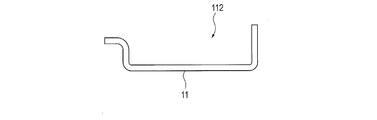
- the guide rail 11 has a concave guide portion 112 having a U-shaped cross section (see FIG. 3).
- An insertion hole 111 through which a fastening member (bolt or the like) 101 for fixing the regulating member 20 is passed is provided in the upper part of the guide rail 11.
- the insertion hole 111 of the guide rail 11 is disposed so as to overlap the fastening portion 109 of the restriction member 20.
- FIG. 4 is a front view showing the moving member 12 of the object moving device 1 according to the present embodiment.
- 5 is a cross-sectional view taken along the line EE of FIG.
- FIG. 6 is a view for explaining the support structure of the window glass that is the moving object W of the moving member 12 of the object moving apparatus 1 according to the present embodiment.
- the moving member 12 supports a window glass that is a window of a door that is the moving object W.
- the moving member 12 is engaged with the guide rail 11 and slides on the guide rail 11 to move up and down.
- the moving member 12 supports the window glass as the moving object W via a plurality of glass holders 122.
- An elastic member 121 is provided on the upper end side of the moving member 12.
- the elastic member 121 is in contact with the regulating member 20 and is disposed so as to move inside the concave guide portion 112 of the guide rail 11 (see FIG. 13A).
- the upper end surface of the elastic member 121 serves as a contact portion 121 ⁇ / b> A that contacts the restriction member 20.
- the elastic member 121 is deformed when coming into contact with the regulating member 20.
- the drum member 15 shown in FIG. 1 is connected to the drive unit 14 and the cable 16 is wound thereon.
- the drum member 15 has a terminal member of the cable 16 fixed thereto, and winds the cable 16 and feeds the cable 16.
- the drum member 15 has a locking portion (not shown) that accommodates the terminal member at the end of the cable 16, and is rotatably accommodated in the housing.
- the drum member 15 is connected to the moving member 12 via the cable 16.
- the drum member 15 is made of, for example, resin.
- the drum member 15 is connected to the cable ends of the ascending cable 161 and the descending cable 162 that are the cables 16, and each accommodates and rotates so that the ascending cable 161 and the descending cable 162 are rotated.
- the drum member 15 is rotatably held by the drum housing 13, and rotates in the forward direction and in the reverse direction by the rotational drive of the drive unit 14.
- the ascending cable 161 and the descending cable 162 are wound in opposite directions.
- the drum member 15 entrains the ascending cable 161 and pulls the ascending cable 161, or entrains the descending cable 162 and pulls the descending cable 162.
- the driving unit 14 is connected to the drum member 15 and is driven by a power source to supply a driving force for rotating the drum member 15 to the drum member 15.
- the drive unit 14 connects the drum member 15 and the drive source so that the drum member 15 rotates by driving of the drive source.
- the drive unit 14 rotates the drum member 15 by the driving force of the drive source, and winds the cable 16 or feeds the cable 16.
- the drive unit 14 includes, for example, a motor that is driven by turning on and off the power supply, and rotates the connected drum member 15.
- the drive unit 14 is accommodated in a motor housing, and is fixed to an attachment target such as a base body or a vehicle body via the motor housing.
- the drive unit 14 is disposed at the lower end of the door panel in the door panel.
- the drive unit 14 of the present embodiment is a motor that is electrically driven by a current supplied from a battery.
- the motor of the drive unit 14 desirably has a so-called clutch function that can lock the output shaft at a predetermined rotation angle.
- the drive unit 14 fits the motor shaft into the center of the drum member 15 and rotates the drum member 15 by the rotation of the motor shaft.
- the motor and the drum member 15 transmit the rotational movement of the motor to the drum member 15 via a power transmission unit such as a worm gear, for example.
- the motor which is the drive unit 14 is rotationally driven in the forward direction and the reverse direction, whereby the drum member 15 is rotated in the forward direction and the reverse direction.
- the drive unit 14 and the drum member 15 are arranged on the second position side.
- the present invention is not limited to this, and the drive unit 14 and the drum member 15 are connected via the cable 16 to the moving member 12.
- the cable 16 may be arranged in any position.
- the drum member 15 that is rotated by the drive unit 14 is provided at a height position between the first position and the second position, and the moving member 12 is connected via the cable 16 that is wound up from the drum member 15 at this position. It is good also as a structure which raises / lowers. In this case, the cable 16 wound up and fed out by the drum member 15 is routed in a hanging manner.
- This configuration includes a first path and a second path that sandwich the drum member 15 and extend in the vertical direction between a first position and a second position that are vertically spaced apart and are parallel to each other,
- the cable 16 wound and fed by the drum member 15 passes from the upper end of the first path to the lower end of the second path, passes through the second path, passes from the upper end of the second path to the lower end of the first path, and passes through the first path. It is routed so as to reach the upper end of one path.
- the moving member 12 is horizontally attached at the cable portion on the first route and the second route, and the cable portion between the upper end of the first route and the lower end of the second route, or the upper end of the second route and the first portion.
- This can be realized by configuring the cable portion between the lower end of the path to move in the extending direction of the cable 16 by the drum member 15.
- the control unit 18 controls the drive of the drive unit 14.
- the control unit 18 is an ECU or the like provided in the vehicle itself, and controls the driving of the motor in the driving unit 14 by the current from the battery.
- the controller 18 moves the moving object W up and down via the moving member 12 by rotating the motor.
- the control unit 18 controls the motor that is the driving unit 14 to rotationally drive the motor in the forward direction and the reverse direction, whereby the drum member 15 rotates in the forward direction and the reverse direction.
- the control unit 18 stops driving of the drive unit 14 due to an overcurrent of the drive unit 14 when the moving member 12 reaches the first position.
- the overcurrent of the drive unit 14 when the moving member 12 reaches the first position is the amount of current supplied to move the moving member 12 that is generated when the moving member 12 is restrained by the movement obstruction. This is the current that is supplied to the drive unit 14 beyond.
- the movement obstruction that restrains the moving member 12 may be the regulating member 20 that regulates the rising of the moving member 12 via the elastically deformed elastic member 121, or the upper end of the window glass that is the moving object W. It may be a door sash that hits.
- the control unit 18 includes a sensor that detects an overcurrent to the motor in the drive unit 14 that is a drive control target.
- the control unit 18 detects the overcurrent when the upper end is restrained on the movement obstruction side of the moving member 12 and, in this embodiment, ON / OFF of the energization to the drive unit. Control such as.
- the cable 16 has one end connected to the moving member 12 and the other end connected to the drum member 15.
- the cable 16 is wound and fed by the rotation of the drum member 15.
- the cable 16 supplies a driving force of a driving source to the moving member 12.
- the cable 16 is locked to the drum member 15 and the moving member 12 by terminal members on both sides. In these locking structures, even when the drum member 15 is rotated, the end members at both ends are engaged with each other so as not to be disengaged from the drum member 15 and the moving member 12, respectively. Good.
- the cable 16 includes an ascending cable 161 and a descending cable 162.
- One end of the ascending cable 161 is connected to the drum member 15, is hung on the direction changing portion 104 of the upper joint member 10, and the other end is connected to the moving member 12.
- the lowering cable 162 has one end connected to the drum member 15 and the other end connected to the moving member 12.
- the direction changing member 19 changes the direction in which the cable 16 extends between the moving member 12 and the drive unit 14.
- the direction changing member 19 changes the extending direction of the cable 16 by contacting the cable 16 and is connected to the drum member 15 through the cable 16.
- the direction changing member 19 switches the direction extending from the drive unit 14 of the lifting cable 161 from the upper direction to the lower direction.
- the direction changing member 19 guides the cable 16 that is wound and fed out through the drum member 15 in accordance with an energization instruction or an energization stop instruction to the drive unit 14 so that the extending direction of the cable 16 is changed.
- the direction change member 19 has the direction change part 104 provided in the upper joint member 10 in this Embodiment.
- the direction changing portion 104 of the direction changing member 19 is disposed on the first position side of the upper joint member 10 fixed to one end side of the guide rail 11.
- the drum member 15 disposed on the second position side also functions as a direction changing member on the second position side.
- the drum member 15 is located between the first position and the second position.
- a lower direction changing member for changing the direction of the lowering cable 162 may be provided on the second position side.
- a cable guide or a pulley is used for the direction changing member 19.
- the direction changing portion 104 that is a direction changing member is provided in the upper joint member 10, and the drum member 15 having a function as the direction changing member is provided in the drum housing 13.
- the direction changing unit 104 changes the moving direction of the rising cable 161 when the rising cable 161 is hooked.
- the direction change part 104 has a guide groove provided in an arc shape, and the moving cable 161 slides on the direction change part 104 to change the moving direction.
- the direction changing unit 104 changes the movement of pulling down one end of the lifting cable 161 downward to the movement of pulling up the other end.
- the pulley provided rotatably in the main-body part of the upper joint member 10 as mentioned above is employ
- the regulating member 20 regulates the movement of the moving member 12.
- the regulating member 20 abuts on the moving member 12, specifically, the elastic member 121 provided on the moving member 12, functions to receive the force from the moving member 12 when the moved moving member 12 hits, and the moving member 12 movement positions are defined.
- the movement of the moving member 12 toward the first position is an upward movement of the moving member 12 by an operation of closing the window.
- the restricting member 20 contacts the moving member 12 when the elastic member 121 reaches the first position, and then undergoes a predetermined elastic deformation.
- the window glass which is the moving object W is fixed to the restriction position where the window glass comes into contact with the sash upper side and the window glass reaches the first position.
- the restriction member 20 is fixed to the attachment target so as not to move due to the contact of the moving member 12.
- the regulating member 20 In a state where the regulating member 20 is in contact with the elastic member 121 of the moving member 12, the regulating member 20 is not positioned at the first position, and the elastic member 121 that abuts on the regulating member 20 is elastically deformed.
- the moving member 12 is positioned at the first position.
- the first position is a position where the window is closed by the window glass that is the moving object W that moves.
- the position of the deadline state is a state in which the window glass is in contact with the door sash in the moving direction, that is, a state in which the window glass is in contact with the bottom surface of the door sash having a concave cross section, and a state in which the window glass is not in contact with the bottom surface of the door sash. Including a position where the concave door sash is inserted into a portion opposed to the bottom surface to substantially close the window.
- the regulating member 20 regulates the movement of the moving object W by regulating the movement of the moving member 12.
- the restricting member 20 is fixed at the restricting position so as to be in contact with the elastic member 121.
- the restricting member 20 is fixed at a restricting position where the elastic member 121 reaches the first position after the elastic member 121 contacts the moving member 12 and undergoes predetermined elastic deformation when the moving member 12 moves to the first position side.
- the restriction position is a position where the moving member 12 is located at the first position. In a state where the window glass as the moving object W is closed in the window provided on the door, the moving member 12 may be located at the first position.
- the restriction position may be a position that is in contact with the moving member 12 and restricts the movement of the moving member 12.
- the moving member 12 By providing the restricting member 20 at the restricting position, the moving member 12 reaches the first position while the elastic member 121 is crushed.
- the moving member 12 that reaches the first position by elastic deformation while the elastic member 121 is crushed is in a state having the crushed elastic member 121.
- the moving member 12 that has reached the first position by the restoring force of elastic deformation rises to a position beyond the first position on the upper end side, and then the moving member 12 is on the opposite side to the upward direction by the restoring force of the elastic member 121. That is, it returns to the lower end side and reaches the first position in a lowered state.
- the restricting position is disposed closer to the driving unit 14 than the direction changing unit 104 that is a direction changing member on the first position side.
- the regulating member 20 is fixed to the upper joint member 10 by the fastening portion 109 in the object moving device 1 of the present embodiment.
- the restricting member 20 is fixed so as not to move relative to the door which is a fixed object of the object moving device 1. Details of the restricting member 20 in the object moving device 1 and the restricting position, which is a fixed position thereof, will be described later.
- the upper joint member 10 is connected to the upper end portion of the guide rail 11.
- the upper joint member 10 is provided with a fitting hole 106 (see FIG. 10) for fitting the guide rail 11.
- the fitting hole 106 is a hole having a shape corresponding to the shape of the cross section of the upper end portion of the guide rail 11, and opens to the bottom surface of the upper joint member 10.
- the upper end of the guide rail 11 is firmly fitted into the fitting hole 106 and is fixed to the upper joint member 10.
- the upper joint member 10 is provided with a fastening portion 105 (see FIG. 1) that is fastened to a vehicle door by a fastening member 101 such as a bolt.
- the fastening portion 105 is provided with an insertion hole 111 through which the fastening member 101 is inserted.
- the upper joint member 10 is fixed to the door of the vehicle by fastening the fastening portion 105 to an inner panel or an outer panel of the vehicle door.
- the upper joint member 10 is made of, for example, resin.
- the drum housing 13 is made of resin, for example, is a member that rotatably accommodates the drum member 15, the drive unit 14 is fixed, the lower end of the guide rail 11 is connected, and is fastened to the door of the vehicle.
- the drum housing 13 is fastened to a vehicle door via a fastening portion.
- the fastening portion is an insertion hole through which a fastening member such as a bolt is passed.
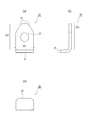
- FIG. 7A and 7B are three views of the regulating member 20.
- FIG. 7A is a front view of the regulating member 20
- FIG. 7B is a side view of the regulating member 20
- FIG. FIG. 8 is a diagram for explaining a restriction position of the restriction member 20.
- the regulating member 20 collides with the elastic member 121 provided on the moving member 12 and regulates the raised position of the moving member 12.
- the regulating member 20 is disposed inside the concave guide portion 112 of the guide rail 11.
- the restricting member 20 includes a base portion 20A having a certain thickness and a restricting portion 21 protruding in one of the thickness directions of the base portion 20A.
- the restricting portion 21 is provided in the lower portion of the base portion 20A.
- the base portion 20 ⁇ / b> A is provided with a hole portion 22 for inserting the fastening member 101 and fixing the regulating member 20, and a tapered portion 24.
- the hole 22 has a width through which the fastening member 101 penetrates.
- the restriction member 20 You may make it fix in the position shifted in the longitudinal direction of the part 22.
- the tapered portion 24 is provided on the upper portion of the regulating member 20 and is provided so that the lateral width of the base portion 20A gradually increases from the upper side to the lower side.
- the taper portion 24 is formed from the vicinity of the upper end of the base portion 20A to a position reaching the upper end of the hole portion 22 in the vertical direction.
- FIG. 9 is a bottom view showing the upper joint member 10.
- 10 is a cross-sectional view of the upper joint member 10.
- FIG. 10 (a) is a cross-sectional view taken along the line AA
- FIG. 10 (b) is a cross-sectional view taken along the line BB
- FIG. 10C is a cross-sectional view taken along the line CC
- FIG. 10D is a cross-sectional view taken along the line DD.
- FIG. 11 is a longitudinal sectional view showing a state in which the regulating member 20 is fixed to the upper joint member 10.
- the upper joint member 10 is provided with a fitting hole 106 and a fixing hole 107.
- the fitting hole 106 is a hole that fits with the upper end portion of the guide rail 11 as described above.
- the fixing hole 107 is a hole that opens to the bottom surface of the upper joint member 10 and into which the upper portion of the restriction member 20 can be inserted and the restriction member 20 can be pushed upward.
- the fixing hole 107 is formed adjacent to or continuously with the fitting hole 106 into which the guide rail 11 is fitted.
- the fixing hole 107 is provided along the bottom surface (the bottom surface of the recess) of the concave guide portion 112 of the guide rail 11 fitted in the fitting hole 106.
- the upper joint member 10 is provided with two ribs 108 a and 108 b that sandwich the fixing hole 107 from the left and right.
- the ribs 108 a and 108 b can guide the regulating member 20 into the fixing hole 107.
- the distance L1 between the left rib 108a and the right rib 108b is formed to be the same size or slightly shorter than the lateral width W1 (see FIG. 7A) of the base portion 20A of the regulating member 20.
- Tapered portions d1 and d2 are provided at the lower ends of the rib 108a and the rib 108b, respectively.
- the tapered portions d1 and d2 are provided so that the distance between the right end of the left rib 108a and the left end of the right rib 108b becomes wider as it goes downward.
- Such a tapered portion d1, d2 makes it easy to insert the regulating member 20 into the fixing hole 107 and attach it.
- the fastening portion 109 of the restriction member 20 is provided with an insertion hole 109a perpendicular to the bottom surface of the base portion 20A of the restriction member 20 or the concave guide portion 112 of the guide rail 11. It has been. As shown in FIG.
- the regulating member 20 is inserted into the fixing hole 107 of the upper joint member 10, and the fastening member 101 is passed through the insertion hole 111 of the guide rail 11 and the insertion hole 109 a of the fastening portion 109.
- the upper joint member 10 is fixed.
- a cylindrical collar 102 is fitted into the insertion hole 109 a of the upper joint member 10.
- the fastening member 101 is passed through the collar 102, and is fixed with a washer 103 locked to the tip side.
- the upper joint member 10 has a direction changing portion 104, and the restricting member 20 is fixed so as to be inserted into the direction changing portion 104.
- the fixing hole 107 of the restricting member 20 may communicate with the through hole of the fastening portion 105.
- a fastening member (bolt or the like) 101 that fastens the upper joint member 10 to a vehicle door is passed through the fastening portion 105, and the regulating member 20 is fixed in a state of being inserted into the direction changing portion 104.
- the fastening member 101 may be configured to be fixed to the back of a portion where a part of the regulating member 20 is exposed so that the fastening member 101 and the regulating member 20 do not contact each other.
- the collar 102 and the washer 103 are used, but it goes without saying that the restricting member 20 may be directly fixed to the guide rail 11 without using these.
- FIG. 12 is a perspective view showing a state before and after contact of the elastic member 121 with the regulating member 20
- FIG. 12 (a) is a perspective view showing a state before contact
- FIG. It is a perspective view which shows the state of.
- FIG. 12A when the moving member 12 is lifted from the lower end restraining position side that is the second position, the contact portion 121 ⁇ / b> A of the elastic member 121 of the regulating member 20 is moved as shown in FIG. It abuts on the restricting portion 21.
- the elastic member 121 of the moving member 12 is elastically deformed by pressing the restricting portion 21 of the restricting member 20 with the contact portion 121A, and the elastic member 121 is deformed by moving the elastic member 121. It rises by the amount of the collapsed height.
- the restricting member 20 reaches the first position after being elastically deformed by the elastic member 121 and the restricting member 20.
- the window regulator fastens the glass holder 122 attached to the window glass as the moving object W to the moving member 12 using a fastening member 101 such as a bolt.
- the fixed window glass can move by moving the moving member 12 between the fully open position and the deadline position.
- the window closing operation by the window glass that is the moving object W connected to the moving member 12 by moving the moving member 12 will be described.
- FIGS. 13 to 15 show the operation of the window glass through the moving member 12 of the window regulator
- FIG. 13A is a schematic view showing the window glass when the moving member 12 is located at the lower limit position
- FIG. 13B is a schematic diagram showing the window glass being raised.
- 14A is a schematic view showing the state immediately before the window glass rises to the highest level
- FIG. 14B is an enlarged view of the upper edge portion of the window glass
- FIG. 14C is a regulating member 20 and an elastic member 121.
- FIG. 14D is a schematic view showing the window glass when it is raised to the maximum
- FIG. 14E is an enlarged view of the upper edge portion of the window glass
- FIG. 15A is a schematic diagram showing the window glass after the window glass has been raised most and the drive unit 14 has stopped
- FIG. 15B is an enlarged view of the upper edge portion of the window glass
- FIG. ) Is an enlarged view of portions of the regulating member 20 and the elastic member 121.
- the drive unit 14 is driven by the control of the control unit 18 to raise the moving member 12.
- the moving member 12 raises along the guide rail 11, and the window glass which is the moving object W rises in connection with this.
- the window glass slides up in the door sash F and rises.
- the elastic member 121 of the moving member 12 contacts the regulating member 20 (see FIG. 14A). At this time, the elastic member 121 of the moving member 12 is in contact with the restricting portion 21 of the restricting member 20, and the elastic member 121 is not yet elastically deformed.
- the moving member 12 is lower than the movable uppermost position, and the upper edge of the window glass (movable object W) is a door sash F (also referred to as a door roof) as a movement obstruction or inside the roof. It does not hit the fastener.
- a door sash F also referred to as a door roof
- the elastic member 121 of the moving member 12 presses the regulating member 20 upward as shown in FIG. 14 (d).
- the restricting member 20 since the restricting member 20 is fixed at the restricting position, the restricting member 20 does not move even when pressed by the elastic member 121, and the elastic member 121 is elastically deformed (see FIG. 14F). While the elastic member 121 is elastically deformed and crushed, the moving member 12 further rises, the window glass as the moving object W hits the door sash F, and the rise is restricted at the upper end restraining position (FIG. 14E). reference).
- the upward movement is restricted by the restriction member 20 via the elastic member 121 crushed by the elastic deformation of the movement member 12.
- a brake is applied to the ascent of the moving member 12, and an overcurrent flows to the motor of the drive unit 14.
- the control unit 18 detects this and stops the driving unit 14. Specifically, power supply to the drive unit 14 is stopped. At this time, the window glass tends to move downward from the upper end restraining position by the reaction force received from the door sash F. When the reaction force is strong, the window glass moves from the upper end restraining position, which is the position where the window glass stops. When the window glass moves downward, the moving member 12 connected to the window glass is also lowered, and the window glass may not be closed.
- the bending of the ascending cable 161 and the descending cable 162 can be regulated by the clutch function of the motor connected via the ascending cable 161 and the descending cable 162, but at a desired position. It may not be possible to regulate.
- the downward movement of the window glass that is the moving object W is caused by the restoring force of the elastic member 121 after elastic deformation that comes into contact with the regulating member 20, so that the window glass is closed. It is possible to maintain the original position that is the state (see FIG. 15B and FIG. 15C).
- the drive unit 14 stops after the movement of the window glass as the moving object W is restrained by the door sash F as the movement obstruction, the upper end of the window glass.
- the load on the door sash F at the restraining position can be reduced. Therefore, when the window glass receives the reaction force from the door sash F, the door itself having the window glass does not bulge outward with the upper end of the window glass as a fulcrum.
- the present invention can be used for a window regulator that moves up and down a glass window of a vehicle such as an automobile.
Landscapes
- Engineering & Computer Science (AREA)
- Mechanical Engineering (AREA)
- Window Of Vehicle (AREA)
- Power-Operated Mechanisms For Wings (AREA)
Abstract
第一位置と第二位置との間を移動する移動部材と、ドラム部材と、ドラム部材を回転させる駆動部と、両端に移動部材とドラム部材とが接続され、ドラム部材の回転によって巻取りと繰出しとがされるケーブルと、移動部材と駆動部との間でケーブルの延びる方向を転換する方向転換部材と、を備え、駆動部の駆動により移動部材を移動させる対象物移動装置であって、移動部材の移動を規制する規制部材が第一位置側に設けられ、移動部材は、第一位置側に弾性部材が設けられ、規制部材は、移動部材の第一位置側への移動において、弾性部材が接触して所定の弾性変形をした後に第一位置に到達する規制位置に固定されている対象物移動装置を用いることで、移動対象物が移動阻害物によって移動が拘束された後の駆動部の停止の際に、上端拘束時のドアの車幅方向の変形や移動対象物が停止した位置から動いてしまうことを抑制できる。
Description
本発明は、移動部材を介して接続される移動対象物を移動する対象物移動装置に関する。
ワイヤを介して移動部材に駆動源の駆動力を伝達することで、移動対象物を移動させる対象物移動装置の一例として、車両に取り付けられるウインドウレギュレータが知られている。
例えば、特許文献1に記載のウインドウレギュレータは、移動対象物である窓ガラスが接続される移動部材としてのキャリアプレートと、駆動部と、駆動部の駆動力により回転するドラムと、ドラムに一端が連結され、他端がキャリアプレートに連結されるワイヤと、を備える。
例えば、特許文献1に記載のウインドウレギュレータは、移動対象物である窓ガラスが接続される移動部材としてのキャリアプレートと、駆動部と、駆動部の駆動力により回転するドラムと、ドラムに一端が連結され、他端がキャリアプレートに連結されるワイヤと、を備える。
キャリアプレートに接続された窓ガラスは、移動の上限付近においてドアサッシュにより移動が阻害され、上側への更なる移動が制限される上端位置でドアサッシュに拘束される。このとき、窓ガラスがドアサッシュにより移動が拘束された上端拘束位置においては、窓ガラスは、駆動部によって与えられた上側へと移動する力に対する反力をドアサッシュから受けることになる。
ここで、ドアの窓を閉めるために、窓ガラスが上端拘束位置に達した後に駆動部への通電が停止されると、窓ガラスは、ドアサッシュから受ける反力によって、上端拘束位置から窓ガラスが動いてしまい、反力が強い場合には、窓ガラスが停止した位置である上端拘束位置から動いてしまう場合がある。つまり、移動対象物である窓ガラスの拘束状態にうけた反力が強い場合には、窓ガラスが閉じた状態とすることができない場合もある。
ここで、ドアの窓を閉めるために、窓ガラスが上端拘束位置に達した後に駆動部への通電が停止されると、窓ガラスは、ドアサッシュから受ける反力によって、上端拘束位置から窓ガラスが動いてしまい、反力が強い場合には、窓ガラスが停止した位置である上端拘束位置から動いてしまう場合がある。つまり、移動対象物である窓ガラスの拘束状態にうけた反力が強い場合には、窓ガラスが閉じた状態とすることができない場合もある。
本発明の目的は、移動対象物が移動阻害物によって移動が拘束された後の駆動部の停止の際に、移動対象物が移動時の拘束による過度な負荷を緩和して、本来の移動位置に位置することができる対象物移動装置を提供することにある。
本発明の一態様に係る対象物移動装置は、移動対象物が接続され、第一位置と第二位置との間を移動する移動部材と、ドラム部材と、前記ドラム部材と接続し、前記ドラム部材を回転させる駆動部と、前記移動部材に一端が接続され、前記ドラム部材に他端が接続され、前記ドラム部材の回転によって巻取りと繰出しとがされるケーブルと、前記移動部材と前記駆動部との間で前記ケーブルの延びる方向を転換する方向転換部材と、を備え、前記駆動部の駆動により前記移動部材を移動させる対象物移動装置であって、前記移動部材が移動することを規制する規制部材が第一位置側に設けられ、前記移動部材は、前記第一位置側に弾性部材が設けられ、前記規制部材は、前記移動部材の前記第一位置側への移動において、前記弾性部材が接触して所定の弾性変形をした後に前記第一位置に到達する規制位置に固定されている、構成を採る。
本発明によれば、移動対象物が移動阻害物によって移動が拘束された後の駆動部の停止の際に、移動対象物が停止した位置から動いてしまうことを抑制できる。
以下、本発明の各実施の形態について図面を参照して詳細に説明する。
<対象物移動装置の全体構成>
本実施の形態の対象物移動装置は、取付対象に取り付けられ、移動部材を移動させることで、移動部材に接続された移動対象物を移動させる装置である。本実施の形態では、対象物移動装置1は、図1および図2に示すように、取付対象として、車両のドアのインナーパネルとアウターパネルとの間に固定され、移動対象物W(図6参照)としてのドアの窓(例えばガラス窓)を昇降する装置、所謂、ウインドウレギュレータである。なお、対象物移動装置1は、移動部材12に接続された移動対象物Wを移動させる装置であれば、ウインドウレギュレータに限らず、他の装置にも適用可能である。対象物移動装置1は、例えば、昇降移動する着座部を昇降させる装置に適用できる。また、対象物移動装置1は、歩行の際に、下端に車輪のついたハンドルを車輪から所定長離間するように上下動させて、ハンドルを握る使用者を、着座状態から歩行可能な姿勢にさせて歩行を支援する歩行支援装置にも適用できる。
本実施の形態の対象物移動装置は、取付対象に取り付けられ、移動部材を移動させることで、移動部材に接続された移動対象物を移動させる装置である。本実施の形態では、対象物移動装置1は、図1および図2に示すように、取付対象として、車両のドアのインナーパネルとアウターパネルとの間に固定され、移動対象物W(図6参照)としてのドアの窓(例えばガラス窓)を昇降する装置、所謂、ウインドウレギュレータである。なお、対象物移動装置1は、移動部材12に接続された移動対象物Wを移動させる装置であれば、ウインドウレギュレータに限らず、他の装置にも適用可能である。対象物移動装置1は、例えば、昇降移動する着座部を昇降させる装置に適用できる。また、対象物移動装置1は、歩行の際に、下端に車輪のついたハンドルを車輪から所定長離間するように上下動させて、ハンドルを握る使用者を、着座状態から歩行可能な姿勢にさせて歩行を支援する歩行支援装置にも適用できる。
図1に示す対象物移動装置1は、正面から見た状態であり、移動部材12としてのキャリア部材に接続された移動対象物Wである窓ガラスを移動させる。
対象物移動装置1は、移動対象物Wである窓ガラスを移動させることができ、この移動により窓ガラスが取り付けられた窓について窓の遮蔽状態と開放状態とを切り替える。
対象物移動装置1は、車両のドアパネルに、ガイドレール11のブラケット、ハウジングの固定部を用いて取り付けられる。
なお、本実施の形態においては、特に断らない限り、ウインドウレギュレータのガイドレール11の長手方向を上下方向とし、ウインドウレギュレータが支持する移動対象物Wである窓ガラスに平行で、前記上下方向に垂直な方向を左右方向として説明する。
対象物移動装置1は、移動対象物Wである窓ガラスを移動させることができ、この移動により窓ガラスが取り付けられた窓について窓の遮蔽状態と開放状態とを切り替える。
対象物移動装置1は、車両のドアパネルに、ガイドレール11のブラケット、ハウジングの固定部を用いて取り付けられる。
なお、本実施の形態においては、特に断らない限り、ウインドウレギュレータのガイドレール11の長手方向を上下方向とし、ウインドウレギュレータが支持する移動対象物Wである窓ガラスに平行で、前記上下方向に垂直な方向を左右方向として説明する。
対象物移動装置1は、移動対象物Wとしての窓ガラスが接続される移動部材12と、駆動部14と、ドラム部材15と、ケーブル16と、方向転換部材である方向転換部104が設けられる上ジョイント部材10と、制御部18と、規制部材20(図2参照)と、を備える。また、対象物移動装置1は、ガイドレール11と、ドラムハウジング13と、を備える。
<移動対象物W>
移動対象物Wは、移動部材12に接続され、移動部材12の移動により移動される対象物である。移動対象物Wは、遮蔽状態と、開放状態とを切り替えたり、移動対象となる対象物に配置された物体を移動させたりする。移動対象物Wは、移動阻害物に当接して移動が阻害される。
本実施の形態において、移動対象物Wである窓ガラスは、ドアサッシュと摺動し、ドアサッシュにより移動が阻害される。ドアのサッシュが移動阻害物に相当する。
移動対象物Wは、移動部材12が規制部材20に接触して後述する第一位置に到達することで所定の位置に配される。
移動対象物Wは、本実施の形態では、ケーブル16の巻き取り繰り出しによって移動する移動部材12の移動に追従して移動する。移動対象物Wは、窓ガラスとしたが、例えば、ガラス以外に、金属、樹脂等により形成された窓としてもよい。また、移動対象物Wは、移動部材12に接続される着座部の座面を構成する部材、あるいは、歩行支援装置のハンドルとして、昇降自在に設けられてもよい。
移動対象物Wは、移動部材12に接続され、移動部材12の移動により移動される対象物である。移動対象物Wは、遮蔽状態と、開放状態とを切り替えたり、移動対象となる対象物に配置された物体を移動させたりする。移動対象物Wは、移動阻害物に当接して移動が阻害される。
本実施の形態において、移動対象物Wである窓ガラスは、ドアサッシュと摺動し、ドアサッシュにより移動が阻害される。ドアのサッシュが移動阻害物に相当する。
移動対象物Wは、移動部材12が規制部材20に接触して後述する第一位置に到達することで所定の位置に配される。
移動対象物Wは、本実施の形態では、ケーブル16の巻き取り繰り出しによって移動する移動部材12の移動に追従して移動する。移動対象物Wは、窓ガラスとしたが、例えば、ガラス以外に、金属、樹脂等により形成された窓としてもよい。また、移動対象物Wは、移動部材12に接続される着座部の座面を構成する部材、あるいは、歩行支援装置のハンドルとして、昇降自在に設けられてもよい。
<移動部材12>
図1および図2に示す移動部材12は、移動対象物Wが接続され、第一位置と第二位置との間を移動する。
ここで、第一位置は、移動部材12の移動方向の一方側に設定された任意の位置である。第一位置は、移動部材12の移動限界の一方側の位置であり、移動部材12の一方側の移動の上限端として規定される。本実施形態では、第一位置は、移動部材12の一方側での移動が拘束された状態となる移動部材12の上端位置ともいえる。この位置は、本実施の形態では、移動対象物Wである窓ガラスで窓を完全に遮蔽して締め切りする状態の位置である。第一位置は、規制部材20に接触した後の弾性部材121の弾性変形により到達することとなる。
なお、第一位置は、駆動部14が下端にある場合には、駆動部14に対して遠い側の位置である。また、本実施の形態のように、ガイドレール11を用いる場合では、第一位置は、ガイドレール11の一方側に位置し、上下方向に延在するガイドレール11の上端側の位置である。
図1および図2に示す移動部材12は、移動対象物Wが接続され、第一位置と第二位置との間を移動する。
ここで、第一位置は、移動部材12の移動方向の一方側に設定された任意の位置である。第一位置は、移動部材12の移動限界の一方側の位置であり、移動部材12の一方側の移動の上限端として規定される。本実施形態では、第一位置は、移動部材12の一方側での移動が拘束された状態となる移動部材12の上端位置ともいえる。この位置は、本実施の形態では、移動対象物Wである窓ガラスで窓を完全に遮蔽して締め切りする状態の位置である。第一位置は、規制部材20に接触した後の弾性部材121の弾性変形により到達することとなる。
なお、第一位置は、駆動部14が下端にある場合には、駆動部14に対して遠い側の位置である。また、本実施の形態のように、ガイドレール11を用いる場合では、第一位置は、ガイドレール11の一方側に位置し、上下方向に延在するガイドレール11の上端側の位置である。
一方、第二位置は、移動部材12の移動方向の他方側に設定された任意の位置である。第二位置は、移動部材12の移動限界の他方側の位置であり、移動部材12の他方側の移動の下限位置として規定される。この位置は、本実施の形態では、移動対象物Wである窓
ガラスの移動により窓を全開放する状態の位置である。第二位置は、本実施の形態では、駆動部14を下端に配置した場合では、第二位置は、駆動部14に対して近い側の位置となる。また、第二位置は、本実施の形態のように、ガイドレール11を用いる場合では、ガイドレール11の他方側に位置し、上下方向に延在するガイドレール11の下端側の位置である。
ガラスの移動により窓を全開放する状態の位置である。第二位置は、本実施の形態では、駆動部14を下端に配置した場合では、第二位置は、駆動部14に対して近い側の位置となる。また、第二位置は、本実施の形態のように、ガイドレール11を用いる場合では、ガイドレール11の他方側に位置し、上下方向に延在するガイドレール11の下端側の位置である。
移動部材12は、第一位置と第二位置との間で移動することにより接続された移動対象物Wを移動させ、本実施の形態では、移動対象物Wである窓ガラスを移動させる。移動部材12は、駆動部14の駆動により移動し、駆動部14の停止より移動が停止する。
移動部材12は、駆動部14の駆動によりドラム部材15から繰り出されるケーブル16により移動させられる。
移動部材12は、ケーブル16の端末部材を収容するエンド収容部(図示省略)を有する。本実施の形態では、移動部材12は、移動部材12を上昇させるための上昇用ケーブル161の端末部材を収容するエンド収容部と、移動部材12を下降させるための下降用ケーブル162の端末部材を収容するエンド収容部とを備える。移動部材12の各ケーブル収容部から上昇用ケーブル161と下降用ケーブル162とが、それぞれ導出部分が、移動部材12を上昇或いは下降させる支点となるように導出される。
移動部材12は、本実施の形態では、ガイドレール11により左右方向の移動が規制された状態で、ガイドレール11に上下方向に摺動可能に嵌合するキャリア部材である。
移動部材12であるキャリア部材の形状は、ガイドレール11および移動対象物Wの形状に応じて随時設計変更可能である。移動部材12であるキャリア部材は、本実施の形態では、板状に形成されたキャリアプレートである。本実施の形態では、移動部材12であるキャリア部材には移動対象物Wとしての窓ガラスが接続され、ガイドレール11に嵌合して、ガイドレール11に沿って移動する。
移動部材12は、駆動部14の駆動によりドラム部材15から繰り出されるケーブル16により移動させられる。
移動部材12は、ケーブル16の端末部材を収容するエンド収容部(図示省略)を有する。本実施の形態では、移動部材12は、移動部材12を上昇させるための上昇用ケーブル161の端末部材を収容するエンド収容部と、移動部材12を下降させるための下降用ケーブル162の端末部材を収容するエンド収容部とを備える。移動部材12の各ケーブル収容部から上昇用ケーブル161と下降用ケーブル162とが、それぞれ導出部分が、移動部材12を上昇或いは下降させる支点となるように導出される。
移動部材12は、本実施の形態では、ガイドレール11により左右方向の移動が規制された状態で、ガイドレール11に上下方向に摺動可能に嵌合するキャリア部材である。
移動部材12であるキャリア部材の形状は、ガイドレール11および移動対象物Wの形状に応じて随時設計変更可能である。移動部材12であるキャリア部材は、本実施の形態では、板状に形成されたキャリアプレートである。本実施の形態では、移動部材12であるキャリア部材には移動対象物Wとしての窓ガラスが接続され、ガイドレール11に嵌合して、ガイドレール11に沿って移動する。
移動部材12は、第一位置側に、弾性部材121を有する。
弾性部材121は、弾性変形する部材であり、移動部材12に設けられ、規制部材20に当接する。移動部材12は、弾性部材121が規制部材20に当接することにより、第一位置へ到達する。弾性部材121は、規制部材20と接触して潰れる。弾性部材121は、規制部材20と接触した後も、駆動源によりケーブル16が巻き取られることにより、変形する。
弾性部材121は、弾性変形した状態から復帰する弾性力を有するので、移動対象物が取り付けられた状態の移動部材12を弾性変形した状態から押し返すことができる弾性を有する。弾性部材121は、所定の弾性変形により、移動部材12を第一位置へ移動させることができる。弾性部材121は、例えば、ゴム或いはバネである。本実施の形態では、上昇時での窓ガラスの上端拘束の際においてドア等が湾曲したり、窓ガラスの位置が移動した場合であっても、弾性部材121の復元力により移動対象物Wである窓ガラスを本来の位置である第一位置に戻すことができる。
弾性部材121は、移動対象物Wが移動阻害物によって移動が拘束された後の駆動部14の停止の際に、移動対象物Wが停止した位置から移動することを抑制する。弾性部材121によって移動対象物Wに過度の荷重が掛かることなく、所定の位置に移動部材12を移動させることができる。本実施の形態では、移動対象物Wが窓ガラスであるので、窓ガラスに必要以上の荷重が係ること無く窓ガラスにより窓を閉め切ることができる。
弾性部材121は、対象物移動装置1のようにガイドレール11を有する場合、ガイドレール11に対向して摺動するように移動部材12に設けられる。
弾性部材121は、弾性変形する部材であり、移動部材12に設けられ、規制部材20に当接する。移動部材12は、弾性部材121が規制部材20に当接することにより、第一位置へ到達する。弾性部材121は、規制部材20と接触して潰れる。弾性部材121は、規制部材20と接触した後も、駆動源によりケーブル16が巻き取られることにより、変形する。
弾性部材121は、弾性変形した状態から復帰する弾性力を有するので、移動対象物が取り付けられた状態の移動部材12を弾性変形した状態から押し返すことができる弾性を有する。弾性部材121は、所定の弾性変形により、移動部材12を第一位置へ移動させることができる。弾性部材121は、例えば、ゴム或いはバネである。本実施の形態では、上昇時での窓ガラスの上端拘束の際においてドア等が湾曲したり、窓ガラスの位置が移動した場合であっても、弾性部材121の復元力により移動対象物Wである窓ガラスを本来の位置である第一位置に戻すことができる。
弾性部材121は、移動対象物Wが移動阻害物によって移動が拘束された後の駆動部14の停止の際に、移動対象物Wが停止した位置から移動することを抑制する。弾性部材121によって移動対象物Wに過度の荷重が掛かることなく、所定の位置に移動部材12を移動させることができる。本実施の形態では、移動対象物Wが窓ガラスであるので、窓ガラスに必要以上の荷重が係ること無く窓ガラスにより窓を閉め切ることができる。
弾性部材121は、対象物移動装置1のようにガイドレール11を有する場合、ガイドレール11に対向して摺動するように移動部材12に設けられる。
本実施の形態の対象物移動装置1において、弾性部材121を有する移動部材12と、移動部材12の移動を案内するガイドレール11について説明する。
図3は、本発明の実施の形態に係る対象物移動装置1におけるガイドレール11の端面を示す平面図である。
ガイドレール11は、移動部材12の昇降方向に長く、ほぼ同一形状の横断面が長手方向に延びるレールであり、移動部材12を昇降経路に沿って移動可能に支持する。ガイドレール11は、典型的には、金属プレートから構成され、長手方向に延びる折れ線に沿って折り曲げた形状を有する。ガイドレール11は、横断面の形状がコの字状(図3を参照)となる凹状ガイド部112を有する。ガイドレール11の上部には、規制部材20の固定用の締結部材(ボルト等)101が通される挿通孔111が設けられている。ガイドレール11が上ジョイント部材10に接続されたとき、ガイドレール11の挿通孔111は、規制部材20の締結部109と重なるように配置される。
図3は、本発明の実施の形態に係る対象物移動装置1におけるガイドレール11の端面を示す平面図である。
ガイドレール11は、移動部材12の昇降方向に長く、ほぼ同一形状の横断面が長手方向に延びるレールであり、移動部材12を昇降経路に沿って移動可能に支持する。ガイドレール11は、典型的には、金属プレートから構成され、長手方向に延びる折れ線に沿って折り曲げた形状を有する。ガイドレール11は、横断面の形状がコの字状(図3を参照)となる凹状ガイド部112を有する。ガイドレール11の上部には、規制部材20の固定用の締結部材(ボルト等)101が通される挿通孔111が設けられている。ガイドレール11が上ジョイント部材10に接続されたとき、ガイドレール11の挿通孔111は、規制部材20の締結部109と重なるように配置される。
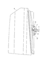
図4は、本実施の形態に係る対象物移動装置1の移動部材12を示す正面図である。図5は、図4のE-E線断面図である。図6は、本実施の形態に係る対象物移動装置1の移動部材12の移動対象物Wである窓ガラスの支持構造を説明する図である。
移動部材12は、移動対象物Wであるドアの窓である窓ガラスを支持する。移動部材12は、本実施の形態では、ガイドレール11に嵌合してガイドレール11に摺動して昇降移動する。
移動部材12は、図6に示すように、複数のガラスホルダ122を介して移動対象物Wとしての窓ガラスを支持する。
移動部材12の上端側に弾性部材121が設けられている。弾性部材121は、規制部材20に当接するものであり、ガイドレール11の凹状ガイド部112の内側を移動するように配置される(図13(a)を参照)。弾性部材121の上端面が、規制部材20に当接する当接部121Aとなる。弾性部材121は、規制部材20に当接した際に変形する。
移動部材12は、移動対象物Wであるドアの窓である窓ガラスを支持する。移動部材12は、本実施の形態では、ガイドレール11に嵌合してガイドレール11に摺動して昇降移動する。
移動部材12は、図6に示すように、複数のガラスホルダ122を介して移動対象物Wとしての窓ガラスを支持する。
移動部材12の上端側に弾性部材121が設けられている。弾性部材121は、規制部材20に当接するものであり、ガイドレール11の凹状ガイド部112の内側を移動するように配置される(図13(a)を参照)。弾性部材121の上端面が、規制部材20に当接する当接部121Aとなる。弾性部材121は、規制部材20に当接した際に変形する。
<ドラム部材15>
図1に示すドラム部材15は、駆動部14と接続され、ケーブル16が巻回される。ドラム部材15は、ケーブル16の端末部材が固定され、ケーブル16の巻き取りおよびケーブル16の繰り出しを行う。ドラム部材15は、本実施の形態では、ケーブル16の端部の端末部材を収容する係止部(図示省略)を有し、ハウジング内に回転可能に収容されている。ドラム部材15は、ケーブル16を介して移動部材12に接続される。ドラム部材15は、例えば、樹脂等により構成される。
本実施の形態では、ドラム部材15は、ケーブル16である上昇用ケーブル161と下降用ケーブル162のケーブルエンドが接続され、それぞれを収容し、回転することにより、上昇用ケーブル161と下降用ケーブル162の巻き取りおよび繰り出しを行う。
ドラム部材15は、ドラムハウジング13に回転可能に保持され、駆動部14の回転駆動により、順方向の回転と、逆方向の回転とを行う。
本実施の形態のドラム部材15は、上昇用ケーブル161と下降用ケーブル162とが、互いに逆向きに捲かれる。ドラム部材15は、回転方向によって、上昇用ケーブル161を巻き込んで上昇用ケーブル161を引っ張るか、下降用ケーブル162を巻き込んで下降用ケーブル162を引っ張る。
図1に示すドラム部材15は、駆動部14と接続され、ケーブル16が巻回される。ドラム部材15は、ケーブル16の端末部材が固定され、ケーブル16の巻き取りおよびケーブル16の繰り出しを行う。ドラム部材15は、本実施の形態では、ケーブル16の端部の端末部材を収容する係止部(図示省略)を有し、ハウジング内に回転可能に収容されている。ドラム部材15は、ケーブル16を介して移動部材12に接続される。ドラム部材15は、例えば、樹脂等により構成される。
本実施の形態では、ドラム部材15は、ケーブル16である上昇用ケーブル161と下降用ケーブル162のケーブルエンドが接続され、それぞれを収容し、回転することにより、上昇用ケーブル161と下降用ケーブル162の巻き取りおよび繰り出しを行う。
ドラム部材15は、ドラムハウジング13に回転可能に保持され、駆動部14の回転駆動により、順方向の回転と、逆方向の回転とを行う。
本実施の形態のドラム部材15は、上昇用ケーブル161と下降用ケーブル162とが、互いに逆向きに捲かれる。ドラム部材15は、回転方向によって、上昇用ケーブル161を巻き込んで上昇用ケーブル161を引っ張るか、下降用ケーブル162を巻き込んで下降用ケーブル162を引っ張る。
<駆動部14>
駆動部14は、ドラム部材15と接続し、電源駆動して、ドラム部材15を回転させる駆動力をドラム部材15に供給する。駆動部14は、駆動源の駆動によりドラム部材15が回転するようにドラム部材15と駆動源とを接続する。駆動部14は、駆動源の駆動力によりドラム部材15を回転し、ケーブル16を巻き取ったり、ケーブル16を繰り出したりする。
駆動部14は、例えば、電源のオンオフによって駆動するモータを含み、接続されたドラム部材15を回転させる。駆動部14は、モーターハウジングに収容され、モーターハウジングを介して基体或いは車体等の取付対象に固定される。本実施の形態では、駆動部14は、ドアのパネル内においてドアパネルの下端部に配置している。
本実施の形態の駆動部14は、バッテリから供給される電流により電気的に駆動するモータである。駆動部14のモータは、出力軸を所定の回転角度でロックできる所謂クラッチ機能を有すること望ましい。
駆動部14は、モータ軸をドラム部材15の中心部に嵌合し、モータ軸の回転によりドラム部材15を回転する。なお、モータとドラム部材15とは、例えば、ウォームギア等の動力伝達部を介してモータの回転運動をドラム部材15に伝達する。駆動部14であるモータは、順方向と逆方向とに回転駆動し、これによりドラム部材15が順方向と逆方向とに回転する。
なお、本実施の形態では、駆動部14及びドラム部材15を第二位置側に配置した構成としたが、これに限らず、駆動部14及びドラム部材15は、ケーブル16を介して移動部材12を昇降可能であればどのような位置に配置し、どのようにケーブル16を配索しても良い。例えば、駆動部14により回転するドラム部材15を、第一位置および第二位置の間の高さの位置に設けて、この位置のドラム部材15から巻き取り繰り出しするケーブル16を介して移動部材12を上昇下降させる構成としてもよい。この場合、ドラム部材15により巻き取り繰り出しされるケーブル16は、たすき掛け状に配索される。この構成は、ドラム部材15を挟み、且つ、上下に離間する第一位置と第二位置の間で上下方向に延在して互いに平行な第1及び第経路と及び第2経路を有し、ドラム部材15で巻き取り繰り出しするケーブル16を、第1経路の上端から第2経路の下端を通り、第2経路を経て第2経路の上端から第1経路の下端を通して、第1経路を経て第1経路の上端に至るように配索される。そして、第1経路および第2経路上のケーブル部分で、移動部材12を水平に取り付けて、第1経路の上端から第2経路の下端の間のケーブル部分、或いは第2経路の上端と第1経路の下端との間のケーブル部分をドラム部材15でケーブル16の延在方向に移動するように構成することにより実現できる。
駆動部14は、ドラム部材15と接続し、電源駆動して、ドラム部材15を回転させる駆動力をドラム部材15に供給する。駆動部14は、駆動源の駆動によりドラム部材15が回転するようにドラム部材15と駆動源とを接続する。駆動部14は、駆動源の駆動力によりドラム部材15を回転し、ケーブル16を巻き取ったり、ケーブル16を繰り出したりする。
駆動部14は、例えば、電源のオンオフによって駆動するモータを含み、接続されたドラム部材15を回転させる。駆動部14は、モーターハウジングに収容され、モーターハウジングを介して基体或いは車体等の取付対象に固定される。本実施の形態では、駆動部14は、ドアのパネル内においてドアパネルの下端部に配置している。
本実施の形態の駆動部14は、バッテリから供給される電流により電気的に駆動するモータである。駆動部14のモータは、出力軸を所定の回転角度でロックできる所謂クラッチ機能を有すること望ましい。
駆動部14は、モータ軸をドラム部材15の中心部に嵌合し、モータ軸の回転によりドラム部材15を回転する。なお、モータとドラム部材15とは、例えば、ウォームギア等の動力伝達部を介してモータの回転運動をドラム部材15に伝達する。駆動部14であるモータは、順方向と逆方向とに回転駆動し、これによりドラム部材15が順方向と逆方向とに回転する。
なお、本実施の形態では、駆動部14及びドラム部材15を第二位置側に配置した構成としたが、これに限らず、駆動部14及びドラム部材15は、ケーブル16を介して移動部材12を昇降可能であればどのような位置に配置し、どのようにケーブル16を配索しても良い。例えば、駆動部14により回転するドラム部材15を、第一位置および第二位置の間の高さの位置に設けて、この位置のドラム部材15から巻き取り繰り出しするケーブル16を介して移動部材12を上昇下降させる構成としてもよい。この場合、ドラム部材15により巻き取り繰り出しされるケーブル16は、たすき掛け状に配索される。この構成は、ドラム部材15を挟み、且つ、上下に離間する第一位置と第二位置の間で上下方向に延在して互いに平行な第1及び第経路と及び第2経路を有し、ドラム部材15で巻き取り繰り出しするケーブル16を、第1経路の上端から第2経路の下端を通り、第2経路を経て第2経路の上端から第1経路の下端を通して、第1経路を経て第1経路の上端に至るように配索される。そして、第1経路および第2経路上のケーブル部分で、移動部材12を水平に取り付けて、第1経路の上端から第2経路の下端の間のケーブル部分、或いは第2経路の上端と第1経路の下端との間のケーブル部分をドラム部材15でケーブル16の延在方向に移動するように構成することにより実現できる。
<制御部18>
制御部18は、駆動部14を駆動制御する。
制御部18は、本実施の形態では、車両自体が備えるECU等であり、バッテリからの電流により駆動部14におけるモータの駆動を制御する。制御部18は、モータを回転させて移動部材12を介して移動対象物Wを昇降する。制御部18は、駆動部14であるモータを制御して、モータを順方向と逆方向とに回転駆動し、これによりドラム部材15が順方向と逆方向とに回転する。
制御部18は、駆動部14を駆動制御する。
制御部18は、本実施の形態では、車両自体が備えるECU等であり、バッテリからの電流により駆動部14におけるモータの駆動を制御する。制御部18は、モータを回転させて移動部材12を介して移動対象物Wを昇降する。制御部18は、駆動部14であるモータを制御して、モータを順方向と逆方向とに回転駆動し、これによりドラム部材15が順方向と逆方向とに回転する。
制御部18は、移動部材12が第一位置へ到達したときの駆動部14の過電流により、駆動部14の駆動を停止させる。移動部材12が第一位置へ到達したときの駆動部14の過電流とは、移動部材12が移動阻害物によって拘束される際に生じる、移動部材12を移動させるために供給される電流量を超えて駆動部14に供給される電流である。なお、移動部材12を拘束する移動阻害物は、弾性変形した弾性部材121を介して移動部材12の上昇を規制する規制部材20であってもよいし、移動対象物Wである窓ガラスの上端が当たるドアサッシュでもよい。
制御部18は、駆動制御対象である駆動部14におけるモータへ過電流を検出するセンサを有し、このセンサにより、規制部材20と移動部材12が当接し、且つ、移動部材12の弾性部材121が弾性変形したことを検出する。このセンサからの検出結果に基づいて、制御部18は、移動部材12の移動阻害物側、本実施の形態では、上端拘束時の過電流を検知して、駆動部への通電のON・OFFなどの制御をする。
制御部18は、駆動制御対象である駆動部14におけるモータへ過電流を検出するセンサを有し、このセンサにより、規制部材20と移動部材12が当接し、且つ、移動部材12の弾性部材121が弾性変形したことを検出する。このセンサからの検出結果に基づいて、制御部18は、移動部材12の移動阻害物側、本実施の形態では、上端拘束時の過電流を検知して、駆動部への通電のON・OFFなどの制御をする。
<ケーブル16>
ケーブル16は、移動部材12に一端が接続されるとともに、ドラム部材15に他端が接続される。ケーブル16は、ドラム部材15の回転によって巻取りと繰出しとがされる。ケーブル16は、移動部材12に駆動源の駆動力を供給する。ケーブル16は、両側の端末部材でドラム部材15および移動部材12にそれぞれ係止する。これらの係止の構造
では、ドラム部材15の回転時においても、両端の端末部材が、それぞれドラム部材15および移動部材12のそれぞれから外れないように係合すればどのように係合されてもよい。
ケーブル16は、移動部材12に一端が接続されるとともに、ドラム部材15に他端が接続される。ケーブル16は、ドラム部材15の回転によって巻取りと繰出しとがされる。ケーブル16は、移動部材12に駆動源の駆動力を供給する。ケーブル16は、両側の端末部材でドラム部材15および移動部材12にそれぞれ係止する。これらの係止の構造
では、ドラム部材15の回転時においても、両端の端末部材が、それぞれドラム部材15および移動部材12のそれぞれから外れないように係合すればどのように係合されてもよい。
本実施の形態では、ケーブル16は、上昇用ケーブル161と、下降用ケーブル162とを有する。
上昇用ケーブル161は、一端がドラム部材15に接続され、上ジョイント部材10の方向転換部104に掛けられ、他端が移動部材12に接続される。ドラム部材15が上昇用ケーブル161を巻き取る方向に回転することで、上昇用ケーブル161が方向転換部104を経由して引かれ、移動部材12を引き上げる。
下降用ケーブル162は、一端がドラム部材15に接続され、他端が移動部材12に接続される。ドラム部材15が下降用ケーブル162を巻き取る方向に回転することで、下降用ケーブル162が引かれ、移動部材12を引き下げる。
上昇用ケーブル161は、一端がドラム部材15に接続され、上ジョイント部材10の方向転換部104に掛けられ、他端が移動部材12に接続される。ドラム部材15が上昇用ケーブル161を巻き取る方向に回転することで、上昇用ケーブル161が方向転換部104を経由して引かれ、移動部材12を引き上げる。
下降用ケーブル162は、一端がドラム部材15に接続され、他端が移動部材12に接続される。ドラム部材15が下降用ケーブル162を巻き取る方向に回転することで、下降用ケーブル162が引かれ、移動部材12を引き下げる。
<方向転換部材19>
方向転換部材19は、移動部材12と駆動部14との間でケーブル16の延びる方向を転換する。
方向転換部材19は、ケーブル16と接触することでケーブル16の延びる方向を転換し、ケーブル16を介してドラム部材15と接続する。
方向転換部材19は、本実施の形態では、上昇用ケーブル161の駆動部14から延びる方向を上方向から下方向へと切り替える。方向転換部材19は、駆動部14への通電指示或いは通電停止指示によりドラム部材15を介して巻き取り繰り出しされるケーブル16について、ケーブル16の延びる方向が換わるようにガイドする。
方向転換部材19は、移動部材12と駆動部14との間でケーブル16の延びる方向を転換する。
方向転換部材19は、ケーブル16と接触することでケーブル16の延びる方向を転換し、ケーブル16を介してドラム部材15と接続する。
方向転換部材19は、本実施の形態では、上昇用ケーブル161の駆動部14から延びる方向を上方向から下方向へと切り替える。方向転換部材19は、駆動部14への通電指示或いは通電停止指示によりドラム部材15を介して巻き取り繰り出しされるケーブル16について、ケーブル16の延びる方向が換わるようにガイドする。
方向転換部材19は、本実施の形態では、上ジョイント部材10に設けられた方向転換部104を有する。
方向転換部材19のうちの方向転換部104は、ガイドレール11の一端側に固定される上ジョイント部材10の第一位置側に配置されている。
なお、本実施の形態では、第二位置側に配置されるドラム部材15が第二位置側の方向転換部材の機能を兼ねているが、ドラム部材15を第一位置と第二位置との間の中間位置に設けた場合には第二位置側に下降用ケーブル162の方向を転換する下側方向転換部材を設けてもよい。なお、方向転換部材19には、例えば、ケーブルガイドやプーリ等が用いられる。本実施の形態では、方向転換部材である方向転換部104は、上ジョイント部材10に設けられ、方向転換部材としての機能を有するドラム部材15は、ドラムハウジング13に設けられている。
方向転換部材19のうちの方向転換部104は、ガイドレール11の一端側に固定される上ジョイント部材10の第一位置側に配置されている。
なお、本実施の形態では、第二位置側に配置されるドラム部材15が第二位置側の方向転換部材の機能を兼ねているが、ドラム部材15を第一位置と第二位置との間の中間位置に設けた場合には第二位置側に下降用ケーブル162の方向を転換する下側方向転換部材を設けてもよい。なお、方向転換部材19には、例えば、ケーブルガイドやプーリ等が用いられる。本実施の形態では、方向転換部材である方向転換部104は、上ジョイント部材10に設けられ、方向転換部材としての機能を有するドラム部材15は、ドラムハウジング13に設けられている。
方向転換部104(図2参照)は、上ジョイント部材10において、上昇用ケーブル161が捲き掛けられて上昇用ケーブル161の移動方向を転換する。
方向転換部104は、円弧状に設けられたガイド溝を有し、上昇用ケーブル161は方向転換部104を摺動して移動方向が転換する。方向転換部104は、上昇用ケーブル161の一端側を下方に引き下げる運動を、他端側を上方に引き上げる運動に転換する。方向転換部104としては、上述したように、上ジョイント部材10の本体部に回転可能に設けられたプーリを採用する。上ジョイント部材10についての詳細は後述する。
方向転換部104は、円弧状に設けられたガイド溝を有し、上昇用ケーブル161は方向転換部104を摺動して移動方向が転換する。方向転換部104は、上昇用ケーブル161の一端側を下方に引き下げる運動を、他端側を上方に引き上げる運動に転換する。方向転換部104としては、上述したように、上ジョイント部材10の本体部に回転可能に設けられたプーリを採用する。上ジョイント部材10についての詳細は後述する。
<規制部材20>
規制部材20は、移動部材12の移動を規制する。規制部材20は、移動部材12、具体的には、移動部材12に設けられる弾性部材121に当接して、移動した移動部材12が当たって、移動部材12からの力を受ける機能し、移動部材12の移動位置を規定する。移動部材12の第一位置側への移動は、窓を閉める操作による移動部材12の上側への移動である。規制部材20は、ケーブル16の巻き取りにより移動する移動部材12の上
側への移動において、第一位置に到達する際に弾性部材121が移動部材12に接触して所定の弾性変形をした後に、移動対象物Wである窓ガラスがサッシュ上側と接触して窓ガラスが第一位置に到達する位置である、規制位置に固定される。規制部材20は、移動部材12の接触により移動しないように取付対象に固定される。
規制部材20は、移動部材12に、移動部材12の弾性部材121に当接した状態では、移動部材12を第一位置に位置させず、規制部材20に当接する弾性部材121が弾性変形した後で移動部材12を第一位置に位置させる。この第一位置は、本実施の形態では、移動する移動対象物Wである窓ガラスにより窓が締め切りされる状態の位置である。締め切り状態の位置とは、窓ガラスが移動方向でドアサッシュに当接した状態、つまり、断面凹状のドアサッシュの底面に窓ガラスが当接した状態と、ドアサッシュの底面に当接しないものの、凹状のドアサッシュにおいて底面を挟み対向する部分に挿入されて実質、窓を閉塞した状態にする位置も含む。
規制部材20は、移動部材12の移動を規制する。規制部材20は、移動部材12、具体的には、移動部材12に設けられる弾性部材121に当接して、移動した移動部材12が当たって、移動部材12からの力を受ける機能し、移動部材12の移動位置を規定する。移動部材12の第一位置側への移動は、窓を閉める操作による移動部材12の上側への移動である。規制部材20は、ケーブル16の巻き取りにより移動する移動部材12の上
側への移動において、第一位置に到達する際に弾性部材121が移動部材12に接触して所定の弾性変形をした後に、移動対象物Wである窓ガラスがサッシュ上側と接触して窓ガラスが第一位置に到達する位置である、規制位置に固定される。規制部材20は、移動部材12の接触により移動しないように取付対象に固定される。
規制部材20は、移動部材12に、移動部材12の弾性部材121に当接した状態では、移動部材12を第一位置に位置させず、規制部材20に当接する弾性部材121が弾性変形した後で移動部材12を第一位置に位置させる。この第一位置は、本実施の形態では、移動する移動対象物Wである窓ガラスにより窓が締め切りされる状態の位置である。締め切り状態の位置とは、窓ガラスが移動方向でドアサッシュに当接した状態、つまり、断面凹状のドアサッシュの底面に窓ガラスが当接した状態と、ドアサッシュの底面に当接しないものの、凹状のドアサッシュにおいて底面を挟み対向する部分に挿入されて実質、窓を閉塞した状態にする位置も含む。
規制部材20は、移動部材12の移動を規制することで移動対象物Wの移動を規制する。規制部材20は、弾性部材121と当接できるように規制位置に固定される。
規制部材20は、移動部材12の第一位置側への移動において、弾性部材121が移動部材12に接触して所定の弾性変形をした後に第一位置に到達する規制位置に固定されている。なお、規制位置は、移動部材12が第一位置に位置する位置である。移動対象物Wである窓ガラスがドアに設けられた窓の閉塞した状態においては、移動部材12が第一位置に位置してもよい。
規制位置は、移動部材12と当接して、移動部材12の移動を規制する位置であればよい。規制部材20が規制位置に設けられることで、移動部材12が、弾性部材121が潰れたままで第一位置に到達される。弾性部材121が潰れたままの弾性変形により第一位置に到達する移動部材12では、潰れた状態の弾性部材121を有する状態となっている。弾性変形の復帰力により第一位置に到達した移動部材12は、移動部材12が上端側の第一位置を越えた位置に上がった後、弾性部材121の復帰力により上昇方向とは逆側、つまり下端側に戻され、下がった状態で第一位置に到達するのである。
規制位置は、第一位置側の方向転換部材である方向転換部104よりも駆動部14側に配置される。
規制部材20は、本実施の形態の対象物移動装置1では、上ジョイント部材10に締結部109により固定されている。規制部材20は、対象物移動装置1の固定対象物であるドアに対し、相対移動しないように固定されることになる。対象物移動装置1における規制部材20、およびその固定される位置である規制位置の詳細については後述する。
規制部材20は、移動部材12の第一位置側への移動において、弾性部材121が移動部材12に接触して所定の弾性変形をした後に第一位置に到達する規制位置に固定されている。なお、規制位置は、移動部材12が第一位置に位置する位置である。移動対象物Wである窓ガラスがドアに設けられた窓の閉塞した状態においては、移動部材12が第一位置に位置してもよい。
規制位置は、移動部材12と当接して、移動部材12の移動を規制する位置であればよい。規制部材20が規制位置に設けられることで、移動部材12が、弾性部材121が潰れたままで第一位置に到達される。弾性部材121が潰れたままの弾性変形により第一位置に到達する移動部材12では、潰れた状態の弾性部材121を有する状態となっている。弾性変形の復帰力により第一位置に到達した移動部材12は、移動部材12が上端側の第一位置を越えた位置に上がった後、弾性部材121の復帰力により上昇方向とは逆側、つまり下端側に戻され、下がった状態で第一位置に到達するのである。
規制位置は、第一位置側の方向転換部材である方向転換部104よりも駆動部14側に配置される。
規制部材20は、本実施の形態の対象物移動装置1では、上ジョイント部材10に締結部109により固定されている。規制部材20は、対象物移動装置1の固定対象物であるドアに対し、相対移動しないように固定されることになる。対象物移動装置1における規制部材20、およびその固定される位置である規制位置の詳細については後述する。
<上ジョイント部材10>
上ジョイント部材10は、ガイドレール11の上端部に接続される。上ジョイント部材10には、ガイドレール11を嵌合する嵌合穴106(図10を参照)が設けられている。嵌合穴106は、ガイドレール11の上端部の横断面の形状に対応した形状を有する穴であり、上ジョイント部材10の底面に開口している。ガイドレール11は、その上端部が嵌合穴106に強く嵌合されて、上ジョイント部材10に固定される。
上ジョイント部材10には、ボルトなどの締結部材101により車両のドアに締結される締結部105(図1を参照)が設けられている。締結部105には、締結部材101が挿通される挿通孔111などが設けられている。締結部105が、車両のドアのインナーパネルまたはアウターパネル等に締結されることで、上ジョイント部材10が車両のドアに固定される。
上ジョイント部材10は、例えば樹脂により構成される。
上ジョイント部材10は、ガイドレール11の上端部に接続される。上ジョイント部材10には、ガイドレール11を嵌合する嵌合穴106(図10を参照)が設けられている。嵌合穴106は、ガイドレール11の上端部の横断面の形状に対応した形状を有する穴であり、上ジョイント部材10の底面に開口している。ガイドレール11は、その上端部が嵌合穴106に強く嵌合されて、上ジョイント部材10に固定される。
上ジョイント部材10には、ボルトなどの締結部材101により車両のドアに締結される締結部105(図1を参照)が設けられている。締結部105には、締結部材101が挿通される挿通孔111などが設けられている。締結部105が、車両のドアのインナーパネルまたはアウターパネル等に締結されることで、上ジョイント部材10が車両のドアに固定される。
上ジョイント部材10は、例えば樹脂により構成される。
<ドラムハウジング13>
ドラムハウジング13は、例えば樹脂により構成され、ドラム部材15を回転可能に収容し、駆動部14が固定され、ガイドレール11の下端部が接続され、車両のドアに締結
される部材である。ドラムハウジング13は、締結部を介して車両のドアに締結される。締結部は、ボルトなどの締結部材が通される挿通孔である。
ドラムハウジング13は、例えば樹脂により構成され、ドラム部材15を回転可能に収容し、駆動部14が固定され、ガイドレール11の下端部が接続され、車両のドアに締結
される部材である。ドラムハウジング13は、締結部を介して車両のドアに締結される。締結部は、ボルトなどの締結部材が通される挿通孔である。
<規制部材20の規制位置>
図7は、規制部材20の三面図であり、図7(a)は規制部材20の正面図、図7(b)は規制部材20の側面図、図7(c)は規制部材20の底面図である。図8は、規制部材20の規制位置を説明する図である。
規制部材20は、移動部材12が上昇したときに、移動部材12に設けられた弾性部材121に衝突して、移動部材12の上昇位置を規制する。図8に示すように、規制部材20は、ガイドレール11の凹状ガイド部112の内側に配置される。
規制部材20は、一定の厚みを有するベース部20Aと、ベース部20Aの厚み方向のうち一方に張り出した規制部21とを有する。規制部21は、ベース部20Aの下部に設けられている。
ベース部20Aには、締結部材101を挿入して規制部材20を固定する孔部22と、テーパー部24とが設けられている。
孔部22は、締結部材101が遊貫する幅を有する。なお、孔部22を、ガイドレール11の長手方向と同一の方向に長い長穴にして、締結部材101を孔部22に貫通して規制部材20を固定する際に、規制部材20が、孔部22の長手方向にずらした位置で固定されるようにしてもよい。
テーパー部24は、規制部材20の上部に設けられ、上方から下方へかけて、ベース部20Aの横幅が徐々に広がるように設けられている。テーパー部24は、ベース部20Aの上端近傍から、上下方向において孔部22の上端に差し掛かる位置まで形成されている。
図7は、規制部材20の三面図であり、図7(a)は規制部材20の正面図、図7(b)は規制部材20の側面図、図7(c)は規制部材20の底面図である。図8は、規制部材20の規制位置を説明する図である。
規制部材20は、移動部材12が上昇したときに、移動部材12に設けられた弾性部材121に衝突して、移動部材12の上昇位置を規制する。図8に示すように、規制部材20は、ガイドレール11の凹状ガイド部112の内側に配置される。
規制部材20は、一定の厚みを有するベース部20Aと、ベース部20Aの厚み方向のうち一方に張り出した規制部21とを有する。規制部21は、ベース部20Aの下部に設けられている。
ベース部20Aには、締結部材101を挿入して規制部材20を固定する孔部22と、テーパー部24とが設けられている。
孔部22は、締結部材101が遊貫する幅を有する。なお、孔部22を、ガイドレール11の長手方向と同一の方向に長い長穴にして、締結部材101を孔部22に貫通して規制部材20を固定する際に、規制部材20が、孔部22の長手方向にずらした位置で固定されるようにしてもよい。
テーパー部24は、規制部材20の上部に設けられ、上方から下方へかけて、ベース部20Aの横幅が徐々に広がるように設けられている。テーパー部24は、ベース部20Aの上端近傍から、上下方向において孔部22の上端に差し掛かる位置まで形成されている。
図9は、上ジョイント部材10を示す底面図である。図10は、上ジョイント部材10の断面図であり、図9の複数の切断線のうち、図10(a)はA-A線断面図、図10(b)はB-B線断面図、図10(c)はC-C線断面図、図10(d)はD-D線断面図である。図11は、上ジョイント部材10に規制部材20が固定された状態を示す縦断面図である。
上ジョイント部材10には、嵌合穴106と固定穴107とが設けられている。これらのうち、嵌合穴106は、先に説明したように、ガイドレール11の上端部と嵌合する穴である。
上ジョイント部材10には、嵌合穴106と固定穴107とが設けられている。これらのうち、嵌合穴106は、先に説明したように、ガイドレール11の上端部と嵌合する穴である。
固定穴107は、上ジョイント部材10の底面に開口し、規制部材20の上部が差し込まれ、規制部材20が上方に押し込まれることができる穴である。固定穴107は、ガイドレール11が嵌合される嵌合穴106に隣接、或いは、連なって形成される。固定穴107は、嵌合穴106に嵌合されたガイドレール11の凹状ガイド部112の底面(凹みの底の面)に沿って設けられている。
上ジョイント部材10は、図10(c)に示すように、固定穴107を左右から挟む、2つのリブ108a、108bが設けられている。リブ108a、108bは、規制部材20を固定穴107に案内することができる。左方のリブ108aと右方のリブ108bの間隔L1は、規制部材20のベース部20Aの横幅W1(図7(a)を参照)と同寸又は少し短く形成されている。これにより、規制部材20が、固定穴107に押し込まれたときに、リブ108a、108bの摩擦力により、規制部材20の位置が保持されて、仮止めされている。
上ジョイント部材10は、図10(c)に示すように、固定穴107を左右から挟む、2つのリブ108a、108bが設けられている。リブ108a、108bは、規制部材20を固定穴107に案内することができる。左方のリブ108aと右方のリブ108bの間隔L1は、規制部材20のベース部20Aの横幅W1(図7(a)を参照)と同寸又は少し短く形成されている。これにより、規制部材20が、固定穴107に押し込まれたときに、リブ108a、108bの摩擦力により、規制部材20の位置が保持されて、仮止めされている。
リブ108aとリブ108bの下端部には、テーパー部d1、d2が、それぞれ設けられている。テーパー部d1、d2は、左のリブ108aの右端と右のリブ108bの左端との間隔が、下方に進むほど広くなるように設けられている。このようなテーパー部d1、d2により、規制部材20を固定穴107に挿入して取り付け易い。
図10(a)~(d)に示すように、規制部材20の締結部109には、規制部材20のベース部20Aまたはガイドレール11の凹状ガイド部112の底面に直交する挿通孔109aが設けられている。図11に示すように、規制部材20は、上ジョイント部材10の固定穴107に差し込まれ、且つ、締結部材101が、ガイドレール11の挿通孔111と、締結部109の挿通孔109aとに通されることで、上ジョイント部材10に固定される。上ジョイント部材10の挿通孔109aには、円筒状のカラー102が嵌入される。締結部材101は、カラー102に通され、先端側にワッシャー103が係止されて、固定される。上ジョイント部材10は、方向転換部104を有しており、規制部材20は、方向転換部104に差し込むように固定される。
なお、図11に示すように、規制部材20の固定穴107は、締結部105の貫通孔に連通していてもよい。そして、規制部材20が上方に押し上げられたときに、規制部材20の一部が締結部105の貫通孔に露出するようにしてもよい。締結部105には、上ジョイント部材10を車両のドアに締結する締結部材(ボルト等)101が通され、規制部材20は、方向転換部104に挿入した状態で固定される。締結部材101は、規制部材20の一部が露出する部分よりも奥に固定されて、締結部材101と規制部材20とが当たらないように構成するとよい。なお、本実施例では、カラー102やワッシャー103を用いているが、これらを用いずに規制部材20を直接ガイドレール11に固定してもよいことは言うまでもない。
図10(a)~(d)に示すように、規制部材20の締結部109には、規制部材20のベース部20Aまたはガイドレール11の凹状ガイド部112の底面に直交する挿通孔109aが設けられている。図11に示すように、規制部材20は、上ジョイント部材10の固定穴107に差し込まれ、且つ、締結部材101が、ガイドレール11の挿通孔111と、締結部109の挿通孔109aとに通されることで、上ジョイント部材10に固定される。上ジョイント部材10の挿通孔109aには、円筒状のカラー102が嵌入される。締結部材101は、カラー102に通され、先端側にワッシャー103が係止されて、固定される。上ジョイント部材10は、方向転換部104を有しており、規制部材20は、方向転換部104に差し込むように固定される。
なお、図11に示すように、規制部材20の固定穴107は、締結部105の貫通孔に連通していてもよい。そして、規制部材20が上方に押し上げられたときに、規制部材20の一部が締結部105の貫通孔に露出するようにしてもよい。締結部105には、上ジョイント部材10を車両のドアに締結する締結部材(ボルト等)101が通され、規制部材20は、方向転換部104に挿入した状態で固定される。締結部材101は、規制部材20の一部が露出する部分よりも奥に固定されて、締結部材101と規制部材20とが当たらないように構成するとよい。なお、本実施例では、カラー102やワッシャー103を用いているが、これらを用いずに規制部材20を直接ガイドレール11に固定してもよいことは言うまでもない。
図12は、弾性部材121の規制部材20への当接前後の状態を示す斜視図であり、図12(a)は当接前の状態を示す斜視図、図12(b)は当接時の状態を示す斜視図である。
図12(a)に示すように、移動部材12が第二位置である下端拘束位置側から上昇すると、図12(b)に示すように、弾性部材121の当接部121Aが規制部材20の規制部21に当接する。移動部材12は更に上昇するので、移動部材12の弾性部材121が当接部121Aで規制部材20の規制部21を押圧して弾性変形し、移動部材12は、弾性部材121が変形することにより潰れた高さの分、上昇する。規制部材20は、弾性部材121と規制部材20により弾性変形した後、第一位置に到達する。
図12(a)に示すように、移動部材12が第二位置である下端拘束位置側から上昇すると、図12(b)に示すように、弾性部材121の当接部121Aが規制部材20の規制部21に当接する。移動部材12は更に上昇するので、移動部材12の弾性部材121が当接部121Aで規制部材20の規制部21を押圧して弾性変形し、移動部材12は、弾性部材121が変形することにより潰れた高さの分、上昇する。規制部材20は、弾性部材121と規制部材20により弾性変形した後、第一位置に到達する。
<対象物移動装置の動作>
続いて、実施の形態の対象物移動装置1であるウインドウレギュレータの動作方法について説明する。なお、ウインドウレギュレータは、移動対象物Wとしての窓ガラスに付随するガラスホルダ122を、移動部材12にボルト等の締結部材101を用いて締結している。固定された窓ガラスは、移動部材12の昇降により全開位置と、締め切り位置との移動を移動可能である。
ここでは、ウインドウレギュレータの動作において、特に、移動部材12を移動して、移動部材12に接続される移動対象物Wである窓ガラスによる窓の締め切り動作を説明する。
続いて、実施の形態の対象物移動装置1であるウインドウレギュレータの動作方法について説明する。なお、ウインドウレギュレータは、移動対象物Wとしての窓ガラスに付随するガラスホルダ122を、移動部材12にボルト等の締結部材101を用いて締結している。固定された窓ガラスは、移動部材12の昇降により全開位置と、締め切り位置との移動を移動可能である。
ここでは、ウインドウレギュレータの動作において、特に、移動部材12を移動して、移動部材12に接続される移動対象物Wである窓ガラスによる窓の締め切り動作を説明する。
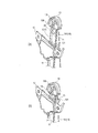
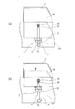
図13~図15は、ウインドウレギュレータの移動部材12を介した窓ガラスの動作を示すもので、図13(a)は移動部材12が下限位置に位置した際の窓ガラスを示す模式図であり、図13(b)は上昇中の窓ガラスを示す模式図である。また、図14(a)は、窓ガラスが最上昇する直前を示す模式図、図14(b)は窓ガラスの上縁部分の拡大図、図14(c)は規制部材20と弾性部材121との部分の拡大図、図14(d)は最上昇したときの窓ガラスを示す模式図、図14(e)は窓ガラスの上縁部分の拡大図、図14(f)は規制部材20と弾性部材121との部分の拡大図である。また、図15(a)は窓ガラスが最上昇し、駆動部14が停止した後の窓ガラスを示す模式図、図15(b)は窓ガラスの上縁部分の拡大図、図15(c)は規制部材20と弾性部材121との部分の拡大図である。
図13(a)の状態において、制御部18の制御により駆動部14を駆動して、移動部材12を上昇させる。すると、図13(b)に示すように、移動部材12はガイドレール11に沿って上昇し、これに伴い移動対象物Wである窓ガラスも上昇する。窓ガラスはドアサッシュF内を摺動して上昇する。
次いで、さらなる上昇の過程において、移動部材12の弾性部材121が、規制部材20に接触する(図14(a)を参照)。このとき、移動部材12の弾性部材121が規制部材20の規制部21に当接した状態であり、弾性部材121は、まだ、弾性変形していない。よって、この状態では、移動部材12は、移動可能な最上方位置より低く、窓ガラス(移動対象物W)の上縁は、移動阻害物としてのドアサッシュF(ドアルーフとも言う)または、ルーフ内留め具に当たっていない。
次いで、さらなる上昇の過程において、移動部材12の弾性部材121が、規制部材20に接触する(図14(a)を参照)。このとき、移動部材12の弾性部材121が規制部材20の規制部21に当接した状態であり、弾性部材121は、まだ、弾性変形していない。よって、この状態では、移動部材12は、移動可能な最上方位置より低く、窓ガラス(移動対象物W)の上縁は、移動阻害物としてのドアサッシュF(ドアルーフとも言う)または、ルーフ内留め具に当たっていない。
さらに、駆動部14の駆動により移動部材12が上昇すると、図14(d)に示すように、移動部材12の弾性部材121が規制部材20を上方に押圧する。このとき、規制部材20は規制位置で固定されているため、規制部材20は、弾性部材121に押圧されても移動せず、弾性部材121が弾性変形する(図14(f)参照)。
弾性部材121が弾性変形して潰れつつ、移動部材12は、更に上昇し、移動対象部物Wである窓ガラスがドアサッシュFに当たり、上端拘束位置で上昇が規制される(図14(e)参照)。或いは、移動部材12が弾性変形により潰れた弾性部材121を介して規制部材20により上方への移動が規制される。
これにより、移動部材12の上昇にブレーキがかかることになり、駆動部14のモータへ過電流が流れる。これを制御部18は検知して、駆動部14を停止する。具体的には駆動部14への通電を停止する。このとき、窓ガラスは、ドアサッシュFから受ける反力によって、窓ガラスが、上端拘束位置から下方に動こうとする。反力が強い場合には、窓ガラスが停止した位置である上端拘束位置から動いてしまう。窓ガラスが下方に移動すると、窓ガラスに接続される移動部材12も下降し、窓ガラスが閉じた状態とすることができない場合がある。
弾性部材121が弾性変形して潰れつつ、移動部材12は、更に上昇し、移動対象部物Wである窓ガラスがドアサッシュFに当たり、上端拘束位置で上昇が規制される(図14(e)参照)。或いは、移動部材12が弾性変形により潰れた弾性部材121を介して規制部材20により上方への移動が規制される。
これにより、移動部材12の上昇にブレーキがかかることになり、駆動部14のモータへ過電流が流れる。これを制御部18は検知して、駆動部14を停止する。具体的には駆動部14への通電を停止する。このとき、窓ガラスは、ドアサッシュFから受ける反力によって、窓ガラスが、上端拘束位置から下方に動こうとする。反力が強い場合には、窓ガラスが停止した位置である上端拘束位置から動いてしまう。窓ガラスが下方に移動すると、窓ガラスに接続される移動部材12も下降し、窓ガラスが閉じた状態とすることができない場合がある。
上昇用ケーブル161および下降用ケーブル162の撓みは、上昇用ケーブル161および下降用ケーブル162を介して接続されたモータのクラッチ機能により、窓ガラスの移動の規制は可能であるが、所望の位置で規制できない場合がある。
これに対し、本実施の形態では、移動対象物Wである窓ガラスの下方への移動が、規制部材20に当接する弾性変形後の弾性部材121の復帰力によって生じるので、窓ガラスが閉じた状態である本来の位置に位置した状態を維持できる(図15(b)および図15(c)参照)。
これに対し、本実施の形態では、移動対象物Wである窓ガラスの下方への移動が、規制部材20に当接する弾性変形後の弾性部材121の復帰力によって生じるので、窓ガラスが閉じた状態である本来の位置に位置した状態を維持できる(図15(b)および図15(c)参照)。
このように、本実施の形態によれば、移動対象物Wである窓ガラスが移動阻害物であるドアサッシュFによって移動が拘束された後の駆動部14の停止の際に、窓ガラスの上端拘束位置でのドアサッシュFへの負荷を緩和することができる。
そのため、ドアサッシFからの反力を窓ガラスが受けることで、窓ガラスを有するドア自体が、窓ガラスの上端を支点にして外方に膨らむことがない。
そのため、ドアサッシFからの反力を窓ガラスが受けることで、窓ガラスを有するドア自体が、窓ガラスの上端を支点にして外方に膨らむことがない。
その他、実施の形態で具体的に示した細部は、発明の趣旨を逸脱しない範囲で適宜変更可能である。
本発明は、自動車などの車両のガラス窓を昇降するウインドウレギュレータに利用できる。
1 対象物移動装置
10 上ジョイント部材
11 ガイドレール
12 移動部材
13 ドラムハウジング
14 駆動部
15 ドラム部材
16 ケーブル
18 制御部
19 方向転換部材
20 規制部材
20A ベース部
21 規制部
22 孔部
101 締結部材
102 カラー
103 ワッシャー
104 方向転換部
105 締結部
106 嵌合穴
107 固定穴
108a、108b リブ
109 締結部
109a 挿通孔
111 挿通孔
112 凹状ガイド部
121 弾性部材
121A 当接部
122 ガラスホルダ
161 上昇用ケーブル
162 下降用ケーブル
F ドアサッシュ
L1 間隔
W 移動対象物
10 上ジョイント部材
11 ガイドレール
12 移動部材
13 ドラムハウジング
14 駆動部
15 ドラム部材
16 ケーブル
18 制御部
19 方向転換部材
20 規制部材
20A ベース部
21 規制部
22 孔部
101 締結部材
102 カラー
103 ワッシャー
104 方向転換部
105 締結部
106 嵌合穴
107 固定穴
108a、108b リブ
109 締結部
109a 挿通孔
111 挿通孔
112 凹状ガイド部
121 弾性部材
121A 当接部
122 ガラスホルダ
161 上昇用ケーブル
162 下降用ケーブル
F ドアサッシュ
L1 間隔
W 移動対象物
Claims (4)
- 移動対象物が接続され、第一位置と第二位置との間を移動する移動部材と、
ドラム部材と、
前記ドラム部材と接続し、前記ドラム部材を回転させる駆動部と、
前記移動部材に一端が接続され、前記ドラム部材に他端が接続され、前記ドラム部材の回転によって巻取りと繰出しとがされるケーブルと、
前記移動部材と前記駆動部との間で前記ケーブルの延びる方向を転換する方向転換部材と、を備え、
前記駆動部の駆動により前記移動部材を移動させる対象物移動装置であって、
前記移動部材の移動を規制する規制部材が第一位置側に設けられ、
前記移動部材は、前記第一位置側に弾性部材が設けられ、
前記規制部材は、前記移動部材の前記第一位置側への移動において、前記弾性部材が接触して所定の弾性変形をした後に前記第一位置に到達する規制位置に固定されている、
対象物移動装置。 - 前記弾性部材は、前記弾性変形した状態からの弾性力によって、移動対象物が取り付けられた状態の移動部材を押し返すことができる弾性を有する、
請求項1に記載の対象物移動装置。 - 前記駆動部を制御する制御部を備え、
前記駆動部が電動駆動し、
前記移動部材が前記第一位置へ到達したときの前記駆動部の過電流により、前記駆動部の駆動を停止させる、
請求項1または請求項2に記載の対象物移動装置。 - 移動対象物が窓ガラスであり、前記移動部材がキャリア部材である、
請求項1から請求項3のいずれかに記載の対象物移動装置を用いた窓ガラス昇降装置。
Priority Applications (1)
| Application Number | Priority Date | Filing Date | Title |
|---|---|---|---|
| HU1900343A HUP1900343A1 (hu) | 2017-02-28 | 2017-12-28 | Tárgymozgató készülék |
Applications Claiming Priority (2)
| Application Number | Priority Date | Filing Date | Title |
|---|---|---|---|
| JP2017-037328 | 2017-02-28 | ||
| JP2017037328A JP6796003B2 (ja) | 2017-02-28 | 2017-02-28 | 対象物移動装置 |
Publications (1)
| Publication Number | Publication Date |
|---|---|
| WO2018159094A1 true WO2018159094A1 (ja) | 2018-09-07 |
Family
ID=63370273
Family Applications (1)
| Application Number | Title | Priority Date | Filing Date |
|---|---|---|---|
| PCT/JP2017/047268 Ceased WO2018159094A1 (ja) | 2017-02-28 | 2017-12-28 | 対象物移動装置 |
Country Status (3)
| Country | Link |
|---|---|
| JP (1) | JP6796003B2 (ja) |
| HU (1) | HUP1900343A1 (ja) |
| WO (1) | WO2018159094A1 (ja) |
Cited By (1)
| Publication number | Priority date | Publication date | Assignee | Title |
|---|---|---|---|---|
| US11562754B2 (en) | 2017-11-10 | 2023-01-24 | Fraunhofer-Gesellschaft Zur F Rderung Der Angewandten Forschung E.V. | Analysis/synthesis windowing function for modulated lapped transformation |
Citations (2)
| Publication number | Priority date | Publication date | Assignee | Title |
|---|---|---|---|---|
| JP2003214029A (ja) * | 2002-01-25 | 2003-07-30 | Honda Motor Co Ltd | 車両用ドア |
| WO2011013641A1 (ja) * | 2009-07-27 | 2011-02-03 | 株式会社ハイレックスコーポレーション | ウインドレギュレータ装置 |
-
2017
- 2017-02-28 JP JP2017037328A patent/JP6796003B2/ja active Active
- 2017-12-28 HU HU1900343A patent/HUP1900343A1/hu unknown
- 2017-12-28 WO PCT/JP2017/047268 patent/WO2018159094A1/ja not_active Ceased
Patent Citations (2)
| Publication number | Priority date | Publication date | Assignee | Title |
|---|---|---|---|---|
| JP2003214029A (ja) * | 2002-01-25 | 2003-07-30 | Honda Motor Co Ltd | 車両用ドア |
| WO2011013641A1 (ja) * | 2009-07-27 | 2011-02-03 | 株式会社ハイレックスコーポレーション | ウインドレギュレータ装置 |
Cited By (2)
| Publication number | Priority date | Publication date | Assignee | Title |
|---|---|---|---|---|
| US11562754B2 (en) | 2017-11-10 | 2023-01-24 | Fraunhofer-Gesellschaft Zur F Rderung Der Angewandten Forschung E.V. | Analysis/synthesis windowing function for modulated lapped transformation |
| US12033646B2 (en) | 2017-11-10 | 2024-07-09 | Fraunhofer-Gesellschaft zur Förderung der angewandten Forschung e.V. | Analysis/synthesis windowing function for modulated lapped transformation |
Also Published As
| Publication number | Publication date |
|---|---|
| JP6796003B2 (ja) | 2020-12-02 |
| HUP1900343A1 (hu) | 2020-08-28 |
| JP2018141332A (ja) | 2018-09-13 |
Similar Documents
| Publication | Publication Date | Title |
|---|---|---|
| JPWO2013062060A1 (ja) | ウインドレギュレータ | |
| JP6423319B2 (ja) | ウインドウレギュレータおよびその取付方法 | |
| CN112145018A (zh) | 对象物移动装置 | |
| JP5925198B2 (ja) | ウインドレギュレータ | |
| WO2018159094A1 (ja) | 対象物移動装置 | |
| KR101425921B1 (ko) | 개선된 풀리장착구조를 가지는 자동차용 윈도우 레귤레이터 | |
| JP2016032984A (ja) | サンルーフ装置 | |
| CN114423923B (zh) | 驱动装置及窗玻璃升降装置 | |
| CN110409950A (zh) | 对象物移动装置及窗玻璃升降装置 | |
| CN110114546B (zh) | 车辆用窗玻璃升降机构 | |
| KR101716410B1 (ko) | 자동차용 윈도우 레귤레이터 | |
| WO2019208830A1 (ja) | 対象物移動装置 | |
| WO2016136890A1 (ja) | 駆動力の伝達機構及びウインドレギュレータ | |
| KR101991778B1 (ko) | 자동차용 윈도우 레귤레이터 | |
| JP2019094701A (ja) | 窓ガラス昇降装置 | |
| JPH08226277A (ja) | ウインドウガラスレギュレータ | |
| WO2015115638A1 (ja) | ウインドレギュレータ | |
| JP2014088670A (ja) | ウインドレギュレータ | |
| JP2008252993A (ja) | 給電箱 | |
| JP2019082033A (ja) | 移動装置及び窓ガラス昇降装置 | |
| JP2020133109A (ja) | ガイドレスレギュレータ | |
| CN121897240A (zh) | 车窗调节器 | |
| KR100318603B1 (ko) | 자동차의 윈도우레귤레이터 | |
| KR100400812B1 (ko) | 자동차의 윈도우레귤레이터 | |
| JP2005206154A (ja) | シートスライド装置のロック機構 |
Legal Events
| Date | Code | Title | Description |
|---|---|---|---|
| 121 | Ep: the epo has been informed by wipo that ep was designated in this application |
Ref document number: 17899206 Country of ref document: EP Kind code of ref document: A1 |
|
| NENP | Non-entry into the national phase |
Ref country code: DE |
|
| 122 | Ep: pct application non-entry in european phase |
Ref document number: 17899206 Country of ref document: EP Kind code of ref document: A1 |