WO2018159005A1 - Exposure device, substrate treatment device, substrate exposure method, and substrate treatment method - Google Patents
Exposure device, substrate treatment device, substrate exposure method, and substrate treatment method Download PDFInfo
- Publication number
- WO2018159005A1 WO2018159005A1 PCT/JP2017/036074 JP2017036074W WO2018159005A1 WO 2018159005 A1 WO2018159005 A1 WO 2018159005A1 JP 2017036074 W JP2017036074 W JP 2017036074W WO 2018159005 A1 WO2018159005 A1 WO 2018159005A1
- Authority
- WO
- WIPO (PCT)
- Prior art keywords
- substrate
- light
- vacuum ultraviolet
- unit
- illuminance
- Prior art date
Links
Images


Classifications
-
- G—PHYSICS
- G03—PHOTOGRAPHY; CINEMATOGRAPHY; ANALOGOUS TECHNIQUES USING WAVES OTHER THAN OPTICAL WAVES; ELECTROGRAPHY; HOLOGRAPHY
- G03F—PHOTOMECHANICAL PRODUCTION OF TEXTURED OR PATTERNED SURFACES, e.g. FOR PRINTING, FOR PROCESSING OF SEMICONDUCTOR DEVICES; MATERIALS THEREFOR; ORIGINALS THEREFOR; APPARATUS SPECIALLY ADAPTED THEREFOR
- G03F7/00—Photomechanical, e.g. photolithographic, production of textured or patterned surfaces, e.g. printing surfaces; Materials therefor, e.g. comprising photoresists; Apparatus specially adapted therefor
- G03F7/20—Exposure; Apparatus therefor
- G03F7/2002—Exposure; Apparatus therefor with visible light or UV light, through an original having an opaque pattern on a transparent support, e.g. film printing, projection printing; by reflection of visible or UV light from an original such as a printed image
- G03F7/2004—Exposure; Apparatus therefor with visible light or UV light, through an original having an opaque pattern on a transparent support, e.g. film printing, projection printing; by reflection of visible or UV light from an original such as a printed image characterised by the use of a particular light source, e.g. fluorescent lamps or deep UV light
-
- G—PHYSICS
- G03—PHOTOGRAPHY; CINEMATOGRAPHY; ANALOGOUS TECHNIQUES USING WAVES OTHER THAN OPTICAL WAVES; ELECTROGRAPHY; HOLOGRAPHY
- G03F—PHOTOMECHANICAL PRODUCTION OF TEXTURED OR PATTERNED SURFACES, e.g. FOR PRINTING, FOR PROCESSING OF SEMICONDUCTOR DEVICES; MATERIALS THEREFOR; ORIGINALS THEREFOR; APPARATUS SPECIALLY ADAPTED THEREFOR
- G03F7/00—Photomechanical, e.g. photolithographic, production of textured or patterned surfaces, e.g. printing surfaces; Materials therefor, e.g. comprising photoresists; Apparatus specially adapted therefor
- G03F7/20—Exposure; Apparatus therefor
-
- G—PHYSICS
- G03—PHOTOGRAPHY; CINEMATOGRAPHY; ANALOGOUS TECHNIQUES USING WAVES OTHER THAN OPTICAL WAVES; ELECTROGRAPHY; HOLOGRAPHY
- G03F—PHOTOMECHANICAL PRODUCTION OF TEXTURED OR PATTERNED SURFACES, e.g. FOR PRINTING, FOR PROCESSING OF SEMICONDUCTOR DEVICES; MATERIALS THEREFOR; ORIGINALS THEREFOR; APPARATUS SPECIALLY ADAPTED THEREFOR
- G03F7/00—Photomechanical, e.g. photolithographic, production of textured or patterned surfaces, e.g. printing surfaces; Materials therefor, e.g. comprising photoresists; Apparatus specially adapted therefor
- G03F7/26—Processing photosensitive materials; Apparatus therefor
- G03F7/38—Treatment before imagewise removal, e.g. prebaking
-
- G—PHYSICS
- G03—PHOTOGRAPHY; CINEMATOGRAPHY; ANALOGOUS TECHNIQUES USING WAVES OTHER THAN OPTICAL WAVES; ELECTROGRAPHY; HOLOGRAPHY
- G03F—PHOTOMECHANICAL PRODUCTION OF TEXTURED OR PATTERNED SURFACES, e.g. FOR PRINTING, FOR PROCESSING OF SEMICONDUCTOR DEVICES; MATERIALS THEREFOR; ORIGINALS THEREFOR; APPARATUS SPECIALLY ADAPTED THEREFOR
- G03F7/00—Photomechanical, e.g. photolithographic, production of textured or patterned surfaces, e.g. printing surfaces; Materials therefor, e.g. comprising photoresists; Apparatus specially adapted therefor
- G03F7/70—Microphotolithographic exposure; Apparatus therefor
- G03F7/70008—Production of exposure light, i.e. light sources
- G03F7/70033—Production of exposure light, i.e. light sources by plasma extreme ultraviolet [EUV] sources
-
- G—PHYSICS
- G03—PHOTOGRAPHY; CINEMATOGRAPHY; ANALOGOUS TECHNIQUES USING WAVES OTHER THAN OPTICAL WAVES; ELECTROGRAPHY; HOLOGRAPHY
- G03F—PHOTOMECHANICAL PRODUCTION OF TEXTURED OR PATTERNED SURFACES, e.g. FOR PRINTING, FOR PROCESSING OF SEMICONDUCTOR DEVICES; MATERIALS THEREFOR; ORIGINALS THEREFOR; APPARATUS SPECIALLY ADAPTED THEREFOR
- G03F7/00—Photomechanical, e.g. photolithographic, production of textured or patterned surfaces, e.g. printing surfaces; Materials therefor, e.g. comprising photoresists; Apparatus specially adapted therefor
- G03F7/70—Microphotolithographic exposure; Apparatus therefor
- G03F7/70058—Mask illumination systems
- G03F7/70208—Multiple illumination paths, e.g. radiation distribution devices, microlens illumination systems, multiplexers or demultiplexers for single or multiple projection systems
-
- G—PHYSICS
- G03—PHOTOGRAPHY; CINEMATOGRAPHY; ANALOGOUS TECHNIQUES USING WAVES OTHER THAN OPTICAL WAVES; ELECTROGRAPHY; HOLOGRAPHY
- G03F—PHOTOMECHANICAL PRODUCTION OF TEXTURED OR PATTERNED SURFACES, e.g. FOR PRINTING, FOR PROCESSING OF SEMICONDUCTOR DEVICES; MATERIALS THEREFOR; ORIGINALS THEREFOR; APPARATUS SPECIALLY ADAPTED THEREFOR
- G03F7/00—Photomechanical, e.g. photolithographic, production of textured or patterned surfaces, e.g. printing surfaces; Materials therefor, e.g. comprising photoresists; Apparatus specially adapted therefor
- G03F7/70—Microphotolithographic exposure; Apparatus therefor
- G03F7/70691—Handling of masks or workpieces
- G03F7/70775—Position control, e.g. interferometers or encoders for determining the stage position
-
- H—ELECTRICITY
- H01—ELECTRIC ELEMENTS
- H01L—SEMICONDUCTOR DEVICES NOT COVERED BY CLASS H10
- H01L21/00—Processes or apparatus adapted for the manufacture or treatment of semiconductor or solid state devices or of parts thereof
- H01L21/02—Manufacture or treatment of semiconductor devices or of parts thereof
- H01L21/027—Making masks on semiconductor bodies for further photolithographic processing not provided for in group H01L21/18 or H01L21/34
-
- H—ELECTRICITY
- H01—ELECTRIC ELEMENTS
- H01L—SEMICONDUCTOR DEVICES NOT COVERED BY CLASS H10
- H01L21/00—Processes or apparatus adapted for the manufacture or treatment of semiconductor or solid state devices or of parts thereof
- H01L21/67—Apparatus specially adapted for handling semiconductor or electric solid state devices during manufacture or treatment thereof; Apparatus specially adapted for handling wafers during manufacture or treatment of semiconductor or electric solid state devices or components ; Apparatus not specifically provided for elsewhere
- H01L21/67005—Apparatus not specifically provided for elsewhere
- H01L21/67011—Apparatus for manufacture or treatment
- H01L21/67098—Apparatus for thermal treatment
-
- H—ELECTRICITY
- H01—ELECTRIC ELEMENTS
- H01L—SEMICONDUCTOR DEVICES NOT COVERED BY CLASS H10
- H01L21/00—Processes or apparatus adapted for the manufacture or treatment of semiconductor or solid state devices or of parts thereof
- H01L21/67—Apparatus specially adapted for handling semiconductor or electric solid state devices during manufacture or treatment thereof; Apparatus specially adapted for handling wafers during manufacture or treatment of semiconductor or electric solid state devices or components ; Apparatus not specifically provided for elsewhere
- H01L21/67005—Apparatus not specifically provided for elsewhere
- H01L21/67011—Apparatus for manufacture or treatment
- H01L21/6715—Apparatus for applying a liquid, a resin, an ink or the like
Definitions
- the present invention relates to an exposure apparatus that performs exposure processing on a substrate, a substrate processing apparatus, a substrate exposure method, and a substrate processing method.
- Patent Document 1 describes an exposure apparatus that performs an exposure process on a film (DSA film) containing an induced self-assembled material on a substrate.
- the exposure apparatus has a light emitting part capable of emitting a vacuum ultraviolet ray having a cross-sectional band shape, and is configured to be movable from the front position to the rear position of the light emitting part so that the substrate crosses the path of the vacuum ultraviolet ray from the light emitting part.
- the illuminance of vacuum ultraviolet rays is detected in advance by an illuminance sensor, and the moving speed of the substrate is calculated based on the detected illuminance so that a desired amount of vacuum ultraviolet rays is irradiated.
- the DSA film on the substrate is irradiated with a desired amount of vacuum ultraviolet light by moving the substrate at the calculated moving speed.
- the illuminance sensor deteriorates and its characteristics change. Therefore, the frequency of replacement and maintenance of the illuminance sensor increases. If the illuminance sensor is frequently replaced or maintained, the operation cost of the exposure apparatus increases, and the operation efficiency decreases due to the prolonged operation stop time of the exposure apparatus.
- An object of the present invention is to provide an exposure apparatus, a substrate processing apparatus, an exposure method, and a substrate processing method that can improve the operation efficiency.
- An exposure apparatus includes a light projecting unit provided on a surface to be processed of a substrate so as to be able to irradiate vacuum ultraviolet light, and a vacuum ultraviolet light irradiation period from the light projecting unit to the substrate.
- An illuminance meter that has a light-receiving surface that partially receives light, measures the illuminance of the received vacuum ultraviolet light, a light-shielding unit that intermittently blocks vacuum ultraviolet light from entering the light-receiving surface of the illuminance meter during the irradiation period, and vacuum ultraviolet light And a light projecting control unit that controls the light projecting unit so as to stop the irradiation of the vacuum ultraviolet ray to the substrate based on the illuminance measured by the illuminance meter.
- the processing unit of the substrate is irradiated with vacuum ultraviolet rays by the light projecting unit.
- the irradiation period of the vacuum ultraviolet ray from the light projecting unit to the substrate a part of the vacuum ultraviolet ray is received by the illuminance meter, and the illuminance of the received vacuum ultraviolet ray is measured.
- the incidence of vacuum ultraviolet rays on the light receiving surface of the illuminometer is intermittently blocked by the light shielding portion. Based on the illuminance measured by the illuminometer, the irradiation of the vacuum ultraviolet ray onto the substrate by the light projecting unit is stopped.
- the vacuum illuminator is intermittently irradiated to the illuminometer, the rate of deterioration of the illuminometer decreases. Therefore, the illuminance meter has a long life. Therefore, it is not necessary to frequently replace and maintain the luminometer. Thereby, the operation cost of the exposure apparatus can be reduced and the operation stop time of the exposure apparatus can be minimized. As a result, the operating efficiency of the exposure apparatus can be improved.
- the illuminance meter is provided at a position capable of receiving a part of the vacuum ultraviolet light from the light projecting unit during the irradiation period, and the light shielding unit intermittently injects the vacuum ultraviolet light onto the light receiving surface of the illuminance meter during the irradiation period.
- the light-shielding member movable so as to be blocked by the light-shielding member and the first driving unit that moves the light-shielding member may be included. In this case, the incidence of vacuum ultraviolet rays on the light receiving surface of the illuminometer can be intermittently blocked with a simple configuration.
- the light-shielding unit alternates between a first position where the illuminance meter can receive a part of the vacuum ultraviolet light from the light projecting unit and a second position where the vacuum ultraviolet light from the light projecting unit cannot be received during the irradiation period.
- a second drive unit that is moved to the position may be included. In this case, the incidence of vacuum ultraviolet rays on the light receiving surface of the illuminometer can be intermittently blocked with a simple configuration.
- the light projecting unit is configured to irradiate the entire region on one surface of the substrate and the region outside the substrate with vacuum ultraviolet rays, and the illuminance meter is disposed outside the substrate at least when the vacuum ultraviolet rays are incident on the light receiving surface during the irradiation period. It may be located in the area. In this case, the illuminance meter can measure the illuminance of the vacuum ultraviolet rays without interfering with the substrate.
- the substrate has a circular shape
- the emitting portion of the vacuum ultraviolet ray in the light projecting portion has a rectangular shape including a circular region corresponding to the region of the substrate, and the light receiving surface of the illuminometer is projected during the irradiation period. It may be movably or fixedly arranged at a position where vacuum ultraviolet rays emitted from a corner area excluding a circular area in the light emission part of the light part can enter. In this case, the illuminometer can be arranged without increasing the size of the exposure apparatus.
- the illuminometer may be arranged such that the light receiving surface is positioned at a certain height with respect to the surface to be processed of the substrate in the irradiation period.
- the attenuation rate of the vacuum ultraviolet rays from the light projecting unit to the processing surface of the substrate correlates with the attenuation rate of the vacuum ultraviolet rays from the light projecting unit to the light receiving surface of the illuminance meter. Therefore, it is possible to accurately acquire the illuminance of the vacuum ultraviolet rays irradiated on the processing surface of the substrate based on the illuminance measured by the illuminometer. Thereby, the exposure amount of the substrate can be accurately calculated based on the illuminance measured by the illuminometer.
- the illuminometer may be arranged such that the light receiving surface is positioned at the same height as the surface to be processed of the substrate during the irradiation period.
- the attenuation rate of the vacuum ultraviolet rays until reaching the processing surface of the substrate from the light projecting portion is equal to the attenuation rate of the vacuum ultraviolet rays until reaching the light receiving surface of the illuminometer from the light projecting portion.
- the illuminance of the vacuum ultraviolet rays applied to the surface to be processed of the substrate is equal to the illuminance measured by the illuminometer.
- the exposure amount of the substrate can be more easily calculated based on the illuminance measured by the illuminometer.
- the exposure apparatus is provided below the light projecting unit in the processing chamber containing the substrate to be processed and the processing chamber, and between the processing chamber and the outside.
- the mounting unit moves to the third position when the substrate is transferred, and the mounting unit moves to the fourth position above the third position when the light emitting unit emits the vacuum ultraviolet rays.
- the substrate can be easily transferred between the processing chamber and the outside without interfering with the light projecting unit.
- the light source unit and the substrate are close to each other, so that the substrate can be efficiently exposed.
- the illuminance meter may move up and down following the movement of the placement unit.
- the light receiving surface of the illuminometer is positioned at a certain height with reference to the surface to be processed of the substrate during the vacuum ultraviolet irradiation period. Therefore, even when the substrate is irradiated with vacuum ultraviolet rays during the movement of the mounting portion, an accurate exposure amount of the substrate is calculated. Therefore, even after the substrate is carried into the processing chamber, the substrate is exposed to the vacuum ultraviolet ray even in the process in which the mounting portion moves between the third position and the fourth position, thereby exposing the substrate in a shorter time. Can be terminated.
- the placement unit may include a first part on which the substrate is placed and a second part on which the illuminance meter is placed when receiving vacuum ultraviolet light.
- the illuminometer can be easily moved in the vertical direction following the movement of the placement portion.
- a substrate processing apparatus includes a coating processing unit that forms a film on a substrate by applying a processing liquid to the substrate, and a thermal processing unit that heat-treats the substrate on which the film is formed by the coating processing unit. And an exposure apparatus according to one aspect of the present invention that exposes the substrate heat-treated by the heat treatment unit, and a development processing unit that develops a film on the substrate by supplying a solvent to the substrate exposed by the exposure device.
- a film is formed on the substrate by applying the processing liquid to the substrate by the coating processing unit.
- the substrate on which the film is formed by the coating processing unit is heat-treated by the heat treatment unit.
- the substrate heat-treated by the heat treatment unit is exposed by the exposure apparatus.
- the film on the substrate is developed by supplying a solvent to the substrate exposed by the exposure apparatus by the development processing unit.
- the vacuum ultraviolet ray is intermittently irradiated to the illuminometer, the deterioration rate of the illuminometer is reduced, and the illuminometer extends its life. Thereby, the operation cost of the exposure apparatus can be reduced and the operation stop time of the exposure apparatus can be minimized. As a result, the operating efficiency of the exposure apparatus can be improved.
- the treatment liquid may include an induced self-organizing material.
- microphase separation occurs on one surface of the substrate by heat-treating the substrate coated with the treatment liquid containing the induced self-organizing material. Further, the substrate on which two types of polymer patterns are formed by microphase separation is exposed and developed. Thereby, one of the two types of polymers is removed, and a fine pattern can be formed.
- An exposure method includes a step of irradiating a processing surface of a substrate with vacuum ultraviolet light by a light projecting unit, and a period of irradiation of vacuum ultraviolet light from the light projecting unit to the substrate with an illuminometer.
- the illuminance meter is intermittently irradiated with vacuum ultraviolet rays, the deterioration rate of the illuminance meter is reduced, and the illuminance meter is prolonged. Thereby, the operation cost of the exposure apparatus can be reduced and the operation stop time of the exposure apparatus can be minimized. As a result, the operating efficiency of the exposure apparatus can be improved.
- a substrate processing method in which a film is formed on a substrate by applying a processing liquid to a surface to be processed of the substrate by a coating processing unit, and the coating processing unit forms a film.
- the substrate after film formation and before development is exposed to vacuum ultraviolet rays.
- the illuminance meter is intermittently irradiated with vacuum ultraviolet rays, the rate of deterioration of the illuminance meter is reduced and the illuminance meter is extended in life. Thereby, the operation cost of the exposure apparatus can be reduced and the operation stop time of the exposure apparatus can be minimized. As a result, the operating efficiency of the exposure apparatus can be improved.
- FIG. 1 is a schematic sectional view showing the arrangement of an exposure apparatus according to the first embodiment of the present invention.
- FIG. 2 is a diagram for explaining the arrangement of the illuminance meter.
- FIG. 3 is a cross-sectional perspective view of the exposure apparatus.
- FIG. 4 is a longitudinal sectional view of the exposure apparatus.
- FIG. 5 is a graph showing the relationship between the oxygen concentration in the housing and the exhaust time.
- FIG. 6 is a graph showing the relationship between the illuminance of vacuum ultraviolet rays applied to the substrate by the light source unit and the lighting time of the light source unit.
- FIG. 7 is a functional block diagram showing the configuration of the control unit of FIG.
- FIG. 8 is a schematic diagram for explaining the operation of the exposure apparatus.
- FIG. 1 is a schematic sectional view showing the arrangement of an exposure apparatus according to the first embodiment of the present invention.
- FIG. 2 is a diagram for explaining the arrangement of the illuminance meter.
- FIG. 3 is a cross-section
- FIG. 9 is a schematic diagram for explaining the operation of the exposure apparatus.
- FIG. 10 is a schematic diagram for explaining the operation of the exposure apparatus.
- FIG. 11 is a schematic diagram for explaining the operation of the exposure apparatus.
- FIG. 12 is a flowchart showing an example of an exposure process performed by the control unit of FIG.
- FIG. 13 is a flowchart showing an example of an exposure process performed by the control unit of FIG.
- FIG. 14 is a flowchart showing an example of exposure processing performed by the control unit of FIG.
- FIG. 15 is a schematic block diagram showing the overall configuration of a substrate processing apparatus provided with the exposure apparatus of FIG.
- FIG. 16 is a schematic view showing an example of substrate processing by the substrate processing apparatus of FIG. FIG.
- FIG. 17 is a cross-sectional perspective view of an exposure apparatus according to the second embodiment of the present invention.
- FIG. 18 is a longitudinal sectional view of the exposure apparatus of FIG.
- FIG. 19 is a cross-sectional perspective view of an exposure apparatus according to the third embodiment of the present invention.
- 20 is a longitudinal sectional view of the exposure apparatus of FIG.
- the term “substrate” refers to a semiconductor substrate, an FPD (Flat Panel Display) substrate such as a liquid crystal display device or an organic EL (Electro Luminescence) display device, an optical disk substrate, a magnetic disk substrate, and a magneto-optical disk. It refers to a substrate, a photomask substrate, a solar cell substrate, or the like.
- FIG. 1 is a schematic sectional view showing the arrangement of an exposure apparatus according to the first embodiment of the present invention.
- the exposure apparatus 100 includes a control unit 110, a processing chamber 120, a closing unit 130, a delivery unit 140, an elevating unit 150, a light projecting unit 160, a replacement unit 170, a measuring unit 180, and a light shielding unit 190.
- the control unit 110 acquires measurement values from the measurement unit 180 and controls operations of the blocking unit 130, the lifting unit 150, the light projecting unit 160, the replacement unit 170, and the light shielding unit 190. The function of the control unit 110 will be described later.
- the processing chamber 120 includes a casing 121 having an upper opening and an internal space, an annular member 122, and a covering member 123.
- a transport opening 121 a for transporting the substrate W to be processed is formed between the inside and the outside of the housing 121.
- a film containing an induced self-organizing material hereinafter referred to as a DSA (Directed Self Assembly) film
- a connecting member 152 of an elevating unit 150 described later passes is formed on the bottom surface of the housing 121.
- the housing 161 of the light projecting unit 160 which will be described later, is disposed on the top of the housing 121 via the annular member 122, whereby the upper opening of the housing 121 is closed.
- Seal members s1 and s2 are attached between the casing 121 and the annular member 122 and between the annular member 122 and the housing 161, respectively.
- a covering member 123 is attached between the housing 121 and the housing 161 so as to cover the outer peripheral surface of the annular member 122.
- the closing part 130 includes a shutter 131, a rod-shaped connecting member 132, and a driving device 133.
- the connecting member 132 connects the shutter 131 and the driving device 133.
- the drive device 133 is a stepping motor, for example.
- the driving device 133 moves the shutter 131 between an open position where the shutter 131 opens the transport opening 121a and a closed position where the shutter 131 closes the transport opening 121a.
- a seal member 131 a is attached to the shutter 131.
- the inside of the housing 121 is hermetically sealed by the seal member 131a being in close contact with a portion of the housing 121 surrounding the transport opening 121a.
- the driving device 133 moves the shutter 131 away from the casing 121 when moving the shutter 131 between the open position and the closed position. Move up and down in the state.
- Position sensors 133a and 133b for detecting the upper limit position and the lower limit position of the shutter 131 are attached to the driving device 133.
- the position sensors 133a and 133b give the detection result to the control unit 110.
- the driving device 133 and driving devices 153 and 192 described later are provided outside the processing chamber 120. Therefore, even when dust is generated by driving the driving devices 133, 153, and 192, the dust is prevented from directly entering the housing 121.
- the delivery unit 140 includes, for example, a disk-shaped support plate 141 and a plurality (three in this example) of support pins 142.
- the support plate 141 is disposed in a horizontal posture within the housing 121.
- an opening 141a is formed through which a connecting member 152 of an elevating unit 150 described later passes.
- the plurality of support pins 142 extend upward from the upper surface of the support plate 141 so as to surround the opening 141a.
- the substrate W to be processed can be placed on the upper ends of the plurality of support pins 142.
- the elevating unit 150 includes a plate-shaped mounting plate 151, a rod-shaped connecting member 152, and a driving device 153.
- the mounting plate 151 is disposed in a horizontal posture above the support plate 141 of the delivery unit 140 in the housing 121.
- a plurality of through holes 151 a corresponding to the plurality of support pins 142 of the support plate 141 are formed in the mounting plate 151.
- the connecting member 152 is disposed to extend vertically through the opening 121 b of the housing 121 and the opening 141 a of the support plate 141, and the driving device 153 is disposed below the housing 121.
- the connecting member 152 connects the mounting plate 151 and the driving device 153.
- a seal member s3 is disposed between the outer peripheral surface of the connecting member 152 and the inner peripheral surface of the opening 121b so that the connecting member 152 can slide in the vertical direction.
- the driving device 153 is, for example, a stepping motor, and moves the mounting plate 151 between a processing position above the upper ends of the plurality of support pins 142 and a standby position below the upper ends of the plurality of support pins 142. Move up and down. In the state where the mounting plate 151 is in the standby position, the plurality of support pins 142 are inserted through the plurality of through holes 151a, respectively.
- Position sensors 153 a and 153 b for detecting the upper limit position and the lower limit position of the mounting plate 151 are attached to the driving device 153. The position sensors 153a and 153b give the detection result to the control unit 110.
- the light projecting unit 160 includes a housing 161 having a lower opening and an internal space, a translucent plate 162, a planar light source unit 163, and a power supply device 164.
- translucent plate 162 is a quartz glass plate.
- the housing 161 is disposed on the upper portion of the housing 121 so as to close the upper opening of the housing 121.
- the translucent plate 162 is attached to the housing 161 so as to close the lower opening of the housing 161.
- the internal space of the housing 121 and the internal space of the housing 161 are separated by a translucent plate 162 so as to be optically accessible.
- the light source unit 163 and the power supply device 164 are accommodated in the housing 161.
- the light source unit 163 is configured by horizontally arranging a plurality of rod-shaped light sources that emit vacuum ultraviolet rays having a wavelength of about 120 nm or more and about 230 nm or less at predetermined intervals.
- Each light source may be, for example, a xenon excimer lamp, or another excimer lamp or a deuterium lamp.
- the light source unit 163 emits vacuum ultraviolet rays having a substantially uniform light amount distribution in the housing 121 through the translucent plate 162.
- the area of the emission surface of the vacuum ultraviolet ray in the light source unit 163 is larger than the area of the surface to be processed of the substrate W.
- the power supply device 164 supplies power to the light source unit 163.
- the replacement unit 170 includes pipes 171p, 172p, 173p, valves 171v, 172v, and a suction device 173.
- the pipes 171p and 172p are connected between an air supply port of the casing 121 and an inert gas supply source.
- the inert gas is, for example, nitrogen gas.
- Valves 171v and 172v are inserted in the pipes 171p and 172p.
- the inert gas is supplied into the housing 121 from the side of the support plate 141 through the pipe 171p.
- An inert gas is supplied into the housing 121 from below the support plate 141 through the pipe 172p.
- the flow rate of the inert gas is adjusted by valves 171v and 172v.
- nitrogen gas is used as the inert gas.
- the pipe 173p branches into a branch pipe 173a and a branch pipe 173b.
- the branch pipe 173 a is connected to the exhaust port of the casing 121, and the end of the branch pipe 173 b is disposed between the casing 121 and the shutter 131.
- a suction device 173 is inserted in the pipe 173p.
- a valve 173v is inserted in the branch pipe 173b.
- the suction device 173 is, for example, an ejector.
- the pipe 173p is connected to the exhaust facility. The suction device 173 discharges the atmosphere in the housing 121 through the branch pipe 173a and the pipe 173p.
- the suction device 173 discharges the atmosphere between the housing 121 and the shutter 131 through the branch pipe 173b and the pipe 173p together with dust and the like generated by the movement of the shutter 131.
- the gas discharged by the suction device 173 is rendered harmless by the exhaust facility.
- the measuring unit 180 includes an oxygen concentration meter 181, an ozone concentration meter 182, and an illuminance meter 183.
- the oxygen concentration meter 181, the ozone concentration meter 182, and the illuminance meter 183 are connected to the control unit 110 through connection ports p 1, p 2, and p 3 provided in the housing 121.
- the oxygen concentration meter 181 is, for example, a galvanic cell type oxygen sensor or a zirconia type oxygen sensor, and measures the oxygen concentration in the housing 121.
- the ozone concentration meter 182 measures the ozone concentration in the housing 121.
- the illuminance meter 183 includes a light receiving element such as a photodiode, and measures the illuminance of vacuum ultraviolet rays from the light source unit 163 irradiated on the light receiving surface of the light receiving element.
- the illuminance is a work rate of vacuum ultraviolet rays irradiated per unit area of the light receiving surface.
- the unit of illuminance is represented by “W / m 2 ”, for example.
- the illuminance meter 183 is attached to the mounting plate 151 so that the light receiving surface of the light receiving element is positioned at substantially the same height as the surface to be processed of the substrate W.
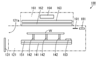
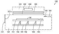
- FIG. 2 is a diagram for explaining the arrangement of the illuminance meter 183.
- the translucent plate 162 has a rectangular shape, and the substrate W has a circular shape. Therefore, the vicinity of the corner portion of the translucent plate 162 does not overlap the substrate W at the processing position in plan view. Therefore, the mounting plate 151 includes a circular portion 151 b that overlaps the central portion of the light transmitting plate 162 and a corner portion 151 c that overlaps in the vicinity of one corner of the light transmitting plate 162 in plan view.
- the substrate W is placed on the circular portion 151b.
- the illuminometer 183 is attached to the corner 151c. According to this arrangement, the illuminance meter 183 can measure the illuminance of vacuum ultraviolet rays without interfering with the substrate W.
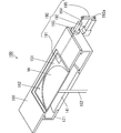
- FIG. 3 is a cross-sectional perspective view of the exposure apparatus 100 of FIG.
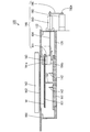
- FIG. 4 is a longitudinal sectional view of the exposure apparatus 100 of FIG. 3 and 4, some components are not shown in order to facilitate understanding of the internal configuration of the exposure apparatus 100.
- the light shielding portion 190 includes a light shielding member 191, a driving device 192, a guide portion 193, a rod-shaped support member 194, and a flat plate-shaped connection member 195.
- the drive device 192 is an air cylinder, for example, and has a drive shaft 192a that can advance and retreat in one direction.
- the driving device 192 is attached to the outer surface of the housing 121.
- the guide portion 193 is attached to the outer surface of the housing 121 and guides the support member 194 so as to be movable in a direction parallel to the forward / backward direction of the drive shaft 192a.
- the support member 194 is provided so as to penetrate the side wall of the housing 121 through the guide portion 193.
- the light shielding member 191 has an inverted L-shaped cross section composed of a horizontal plate 191a and a vertical plate 191b. The lower end of the vertical plate 191 b is attached to one end of the support member 194 in the housing 121.
- the connecting member 195 connects the other end of the support member 194 and the tip of the drive shaft 192 a of the drive device 192 outside the housing 121.
- the light shielding position is the position of the light shielding member 191 that shields the vacuum ultraviolet rays that the horizontal plate 191a irradiates the illuminance meter 183 from the light source unit 163.
- the non-light shielding position is a position of the light shielding member 191 where the horizontal plate 191a does not shield the vacuum ultraviolet rays irradiated from the light source unit 163 to the illuminance meter 183.
- the light shielding member 191 at the light shielding position is illustrated by a solid line
- the light shielding member 191 at the non-light shielding position is illustrated by an alternate long and short dash line.
- FIG. 5 is a graph showing the relationship between the oxygen concentration in the housing 121 and the exhaust time.
- the vertical axis in FIG. 5 indicates the oxygen concentration, and the horizontal axis indicates the exhaust time.
- the oxygen concentration in the housing 121 decreases as the exhaust time increases.
- time t0 when the oxygen concentration measured by the oxygen concentration meter 181 decreases to a predetermined exposure start concentration, irradiation of the vacuum ultraviolet rays from the light source unit 163 to the substrate W is started.
- the exposure start concentration is an oxygen concentration determined in advance so that vacuum ultraviolet rays can reach the substrate W from the light source unit 163 and ozone does not damage the film formed on the surface to be processed of the substrate W.
- the specific exposure start concentration differs depending on the type and components of the film formed on the substrate W to be processed, but is higher than the oxygen concentration of 1% at which almost no oxygen remains in the housing 121 and the atmosphere. Lower than the oxygen concentration inside.
- the oxygen concentration decreases to 1% at time t1.
- the irradiation of the vacuum ultraviolet rays is started at a time t0 that is earlier by ⁇ t than the time t1 when the oxygen concentration is reduced to 1%. Thereby, the time required for the exposure process can be shortened.
- the exposure amount of the vacuum ultraviolet rays applied to the substrate W by the light source unit 163 reaches a predetermined set exposure amount, the irradiation of the vacuum ultraviolet rays is stopped and the exposure process is ended.
- the exposure amount is the energy of vacuum ultraviolet rays irradiated per unit area of the surface to be processed of the substrate W during the exposure process.
- the unit of the exposure amount is represented by “J / m 2 ”, for example. Therefore, the exposure amount of vacuum ultraviolet rays is acquired by integrating the illuminance of vacuum ultraviolet rays measured by the illuminance meter 183.
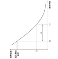
- FIG. 6 is a graph showing the relationship between the illuminance of the vacuum ultraviolet light emitted from the light source unit 163 and the lighting time of the light source unit 163.
- the vertical axis in FIG. 6 indicates the illuminance, and the horizontal axis indicates the lighting time.
- the light source of the light source unit 163 that emits vacuum ultraviolet rays is relatively expensive. Therefore, it is preferable to cut off the power supplied from the power supply device 164 to the light source unit 163 and turn off the light source unit 163 during a period when the substrate W is not irradiated with vacuum ultraviolet rays. Thereby, the lifetime of the light source part 163 can be prolonged.
- the illuminance of the vacuum ultraviolet rays applied to the substrate W decreases with time and converges to a constant value LV after a predetermined time. Therefore, it is difficult to measure the illuminance having a constant value LV before the exposure process.
- vacuum ultraviolet rays are simultaneously irradiated onto the substrate W and the illuminometer 183 during the exposure process. Therefore, when the illuminance of the vacuum ultraviolet rays applied to the substrate W changes, the illuminance of the vacuum ultraviolet rays measured by the illuminance meter 183 changes similarly.
- the illuminance meter 183 is provided such that the light receiving surface of the light receiving element is positioned at substantially the same height as the surface to be processed of the substrate W. Therefore, even when the vacuum ultraviolet rays are partially absorbed and attenuated by oxygen molecules remaining between the substrate W and the light source unit 163, the surface to be processed of the substrate W and the light receiving surface of the illuminometer 183 are approximately the same. Vacuum ultraviolet rays will arrive. The illuminance of the vacuum ultraviolet rays applied to the processing surface of the substrate W is equal to the illuminance measured by the illuminometer 183. As a result, the illuminance of the vacuum ultraviolet rays reaching the substrate W can be accurately measured with a simple configuration.
- the illuminance meter 183 On the other hand, if the illuminance meter 183 is continuously irradiated with vacuum ultraviolet rays for a long period of time, the illuminance meter 183 tends to deteriorate and the life of the illuminance meter 183 decreases. In addition, the frequency of performing maintenance work such as calibration of the illuminance meter 183 increases. In the present embodiment, the light shielding member 191 moves between the light shielding position and the non-light shielding position during the exposure process.
- the illuminometer 183 is intermittently irradiated with vacuum ultraviolet rays, and the deterioration rate of the illuminometer 183 is reduced as compared with the case where the illuminometer 183 is continuously irradiated with vacuum ultraviolet rays.
- the illuminance meter 183 extends its life. Further, the frequency of maintenance work of the illuminance meter 183 can be reduced.
- the illuminance of the vacuum ultraviolet rays applied to the substrate W is not measured during the period in which the light shielding member 191 is in the light shielding position (hereinafter referred to as the light shielding period). Therefore, it is preferable to interpolate the illuminance of the vacuum ultraviolet rays applied to the substrate W during the light shielding period. Interpolation of the illuminance during the light shielding period can be performed based on the illuminance measured by the illuminometer 183 before and after the light shielding period. For example, by connecting the illuminance values measured before and after the light shielding period with a spline curve, the illuminance during the light shielding period can be interpolated with a spline.
- FIG. 7 is a functional block diagram showing the configuration of the control unit 110 in FIG.
- the control unit 110 includes a blockage control unit 1, a lift control unit 2, an exhaust control unit 3, an air supply control unit 4, a concentration acquisition unit 5, a concentration comparison unit 6, a light shielding control unit 7, and illuminance acquisition.
- Unit 8 illuminance interpolation unit 9, exposure amount calculation unit 10, exposure amount comparison unit 11, and light projection control unit 12.
- the control unit 110 includes, for example, a CPU (Central Processing Unit) and a memory.
- a control program is stored in advance in the memory of the control unit 110.
- the function of each unit of the control unit 110 is realized by the CPU of the control unit 110 executing the control program stored in the memory.
- the closing control unit 1 controls the driving device 133 so that the shutter 131 moves between the closing position and the opening position based on the detection results of the position sensors 133a and 133b in FIG.
- the elevation control unit 2 controls the driving device 153 so that the mounting plate 151 moves between the standby position and the processing position based on the detection results of the position sensors 153a and 153b in FIG.
- the exhaust control unit 3 controls the suction device 173 and the valve 173v so as to exhaust the atmosphere in the casing 121 and the atmosphere between the casing 121 and the shutter 131 in FIG.
- the air supply control unit 4 controls the valves 171v and 172v in FIG. 1 so as to supply an inert gas into the housing 121.
- the concentration acquisition unit 5 acquires the value of the oxygen concentration measured by the oxygen concentration meter 181 of FIG.
- the concentration comparison unit 6 compares the oxygen concentration measured by the concentration acquisition unit 5 with the exposure start concentration.
- the light shielding control unit 7 controls the driving device 192 so that the light shielding member 191 in FIG. 4 reciprocates between the light shielding position and the non-light shielding position.
- the illuminance acquisition unit 8 acquires the illuminance value of vacuum ultraviolet rays measured by the illuminometer 183 in FIG.
- the illuminance interpolation unit 9 interpolates the illuminance of the vacuum ultraviolet rays irradiated to the substrate W during the light shielding period based on the control timing of the light shielding member 191 by the light shielding control unit 7 and the illuminance value acquired by the illuminance acquisition unit 8.
- the exposure amount calculation unit 10 illuminates the vacuum ultraviolet rays acquired by the illuminance acquisition unit 8, the illuminance of the vacuum ultraviolet rays interpolated by the illuminance interpolation unit 9, and the irradiation of the vacuum ultraviolet rays from the light source unit 163 in FIG. Based on the time, the exposure amount of the vacuum ultraviolet rays applied to the substrate W is calculated.
- the exposure amount comparison unit 11 compares the exposure amount calculated by the exposure amount calculation unit 10 with a predetermined set exposure amount.
- the light projection control unit 12 controls the supply of power from the power supply device 164 of FIG. 1 to the light source unit 163 so that the light source unit 163 emits vacuum ultraviolet rays based on the comparison result by the concentration comparison unit 6.
- the light projection control unit 12 supplies the exposure amount calculation unit 10 with the power supply time from the power supply device 164 to the light source unit 163 as the irradiation time of the vacuum ultraviolet rays from the light source unit 163 to the substrate W.
- the light projection control unit 12 controls the power supply device 164 so that the light source unit 163 stops the emission of the vacuum ultraviolet rays based on the comparison result by the exposure amount comparison unit 11.
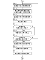
- FIGS. 8 to 11 are schematic diagrams for explaining the operation of the exposure apparatus 100. 8 to 11, in order to facilitate understanding of the configurations in the casing 121 and the housing 161, some components are not shown, and the outlines of the casing 121 and the housing 161 are only one point. Indicated by a chain line. 12, 13 and 14 are flowcharts showing an example of the exposure process performed by the control unit 110 of FIG. Hereinafter, the exposure processing by the control unit 110 will be described with reference to FIGS.
- the shutter 131 in the initial state of the exposure process, the shutter 131 is in the closed position, the mounting plate 151 is in the standby position, and the light shielding member 191 is in the non-light shielding position.
- the oxygen concentration in the housing 121 is constantly or periodically measured by the oxygen concentration meter 181 and acquired by the concentration acquisition unit 5. At this time, the oxygen concentration in the housing 121 measured by the oxygen concentration meter 181 is equal to the oxygen concentration in the atmosphere.
- the closing control unit 1 moves the shutter 131 to the open position (step S1).
- the substrate W to be processed can be placed on the upper ends of the plurality of support pins 142 through the transport opening 121a.
- the substrate W is placed on the upper ends of the plurality of support pins 142 by the transfer device 220 shown in FIG.
- the elevation controller 2 determines whether or not the substrate W is placed on the upper ends of the plurality of support pins 142 (step S2). When the substrate W is not placed, the elevation control unit 2 waits until the substrate W is placed on the upper ends of the plurality of support pins 142. When the substrate W is placed, the elevating control unit 2 moves the shutter 131 to the closed position (step S3).
- the exhaust control unit 3 discharges the atmosphere in the housing 121 by the suction device 173 of FIG. 1 (step S4). Further, the air supply control unit 4 causes the inert gas to be supplied into the housing 121 through the pipes 171p and 172p in FIG. 1 (step S5). Either of the processes of steps S4 and S5 may be started first, or may be started simultaneously. Thereafter, as shown in FIG. 10, the elevation controller 2 raises the placement plate 151 from the standby position to place the substrate W on the placement plate 151 (step S ⁇ b> 6). At this time, the mounting surface of the substrate W and the light receiving surface of the illuminance meter 183 coincide with each other.
- the concentration comparison unit 6 determines whether or not the oxygen concentration in the casing 121 has decreased to the exposure start concentration (step S7).
- the concentration comparison unit 6 stands by until the oxygen concentration decreases to the exposure start concentration.
- the light projection control unit 12 causes the light source unit 163 to emit vacuum ultraviolet rays (step S8).
- vacuum ultraviolet rays are irradiated onto the substrate W from the light source unit 163 through the translucent plate 162, and exposure of the DSA film L3 formed on the surface to be processed is started.
- the raising / lowering control part 2 starts the raise of the mounting plate 151 (step S9).
- the illuminance acquisition unit 8 causes the illuminance meter 183 to start measuring the illuminance of vacuum ultraviolet rays, and acquires the measured illuminance from the illuminance meter 183 (step S10). Further, the light shielding control unit 7 reciprocates the light shielding member 191 a plurality of times between the light shielding position and the non-light shielding position (step S11). Any of the processes in steps S8 to S11 may be started first, or may be started simultaneously.
- the illuminance interpolation unit 9 interpolates the illuminance of the vacuum ultraviolet light during the light shielding period (step S12).
- the exposure amount calculation unit 10 calculates the exposure amount of the vacuum ultraviolet ray irradiated to the substrate W by integrating the illuminance of the vacuum ultraviolet ray acquired by the illuminance acquisition unit 8 and the illuminance of the vacuum ultraviolet ray interpolated by the illuminance interpolation unit 9. (Step S13).
- the elevation controller 2 determines whether or not the placement plate 151 has reached the processing position (step S14). When the mounting plate 151 has not reached the processing position, the elevation control unit 2 proceeds to the process of step S16. On the other hand, when the mounting plate 151 reaches the processing position, the elevation control unit 2 stops the lifting of the mounting plate 151 (step S15). As shown in FIG. 11, when the mounting plate 151 reaches the processing position, the substrate W comes close to the translucent plate 162.
- the exposure amount comparison unit 11 determines whether or not the exposure amount calculated by the exposure amount calculation unit 10 has reached the set exposure amount (step S16). If the exposure amount has not reached the set exposure amount, the exposure amount comparison unit 11 returns to the process of step S10. The processes in steps S10 to S16 are repeated until the exposure amount reaches the set exposure amount.
- the light projection control unit 12 stops the emission of the vacuum ultraviolet rays from the light source unit 163 (step S17).
- the illuminance acquisition unit 8 stops the measurement of illuminance by the illuminometer 183 (step S18).
- the light shielding control unit 7 stops the movement of the light shielding member 191 (step S19). In this example, the light shielding member 191 is returned to the non-light shielding position.
- the elevation controller 2 lowers the placement plate 151 to the standby position (step S20).
- the substrate W is transferred from the placement plate 151 to the plurality of support pins 142.
- the exhaust control unit 3 stops the discharge of the atmosphere in the housing 121 by the suction device 173 (step S21).
- the air supply control unit 4 stops the supply of inert gas from the pipes 171p and 172p into the housing 121 (step S22). Any of the processes in steps S17 to S22 may be started first, or may be started simultaneously.
- the closing control unit 1 moves the shutter 131 to the open position as shown in FIG. 9 (step S23).
- the exposed substrate W can be carried out from the plurality of support pins 142 to the outside of the housing 121 through the transport opening 121a.
- the substrate W is carried out from the plurality of support pins 142 to the outside of the housing 121 by the transfer device 220 shown in FIG.
- the closing control unit 1 determines whether or not the substrate W has been unloaded from the plurality of support pins 142 (step S24). When the substrate W has not been unloaded, the closing control unit 1 stands by until the substrate W is unloaded from the plurality of support pins 142. When the substrate W is carried out, the closing control unit 1 moves the shutter 131 to the closing position as shown in FIG. 8 (step S25), and ends the exposure process. By repeating the above operation, exposure processing can be sequentially performed on the plurality of substrates W.
- the substrate W is irradiated with vacuum ultraviolet rays from the light source unit 163 before the mounting plate 151 is moved to the processing position.
- the substrate W is irradiated with vacuum ultraviolet rays even in the process in which the mounting plate 151 moves from the standby position to the processing position. Therefore, the exposure of the substrate W is completed in a shorter time. Thereby, the efficiency of the exposure processing of the substrate W can be further improved.
- the substrate W may be irradiated with vacuum ultraviolet rays after the mounting plate 151 is moved to the processing position. That is, the processes of steps S9, S14, and S15 may be performed during the processes of steps S6 to S8, or may be performed simultaneously with the process of step S7.
- the mounting plate 151 can be moved to the standby position during a period in which the oxygen concentration in the housing 121 is reduced to the exposure start concentration. Therefore, the exposure of the substrate W is completed in a shorter time. Thereby, the efficiency of the exposure processing of the substrate W can be further improved.
- the placement plate 151 moves from the processing position to the standby position after the exposure amount of the substrate W reaches the set exposure amount, but the present invention is not limited to this.
- the mounting plate 151 may move from the processing position to the standby position before the exposure amount of the substrate W reaches the set exposure amount. That is, the process of step S20 may be executed before the process of step S16.
- the substrate W is irradiated with vacuum ultraviolet rays even in the process in which the mounting plate 151 moves from the processing position to the standby position. Therefore, the substrate W is unloaded from the processing chamber 120 at an earlier time point, and the exposure process ends. Thereby, the efficiency of the exposure processing of the substrate W can be further improved.
- FIG. 15 is a schematic block diagram showing the overall configuration of a substrate processing apparatus provided with the exposure apparatus 100 of FIG.
- processing using block copolymer induced self-assembly is performed.
- a processing liquid containing an induction self-organizing material is applied on the surface of the substrate W to be processed.
- two types of polymer patterns are formed on the surface to be processed of the substrate W by microphase separation that occurs in the induced self-assembled material.
- One of the two types of polymers is removed by the solvent.
- the treatment liquid containing the induced self-organizing material is called DSA liquid.
- DSA liquid a process for removing one of the two types of polymer patterns formed on the surface to be processed of the substrate W by microphase separation
- a developer a solvent used for the development process
- the substrate processing apparatus 200 includes a control device 210, a transport device 220, a heat treatment device 230, a coating device 240, and a developing device 250 in addition to the exposure device 100.
- the control device 210 includes, for example, a CPU and a memory or a microcomputer, and controls operations of the transport device 220, the heat treatment device 230, the coating device 240, and the developing device 250.
- the control device 210 gives a command for controlling the operation of the closing unit 130, the elevating unit 150, the light projecting unit 160, the replacement unit 170, and the light shielding unit 190 of the exposure apparatus 100 of FIG.
- the transport apparatus 220 transports the substrate W between the exposure apparatus 100, the heat treatment apparatus 230, the coating apparatus 240, and the development apparatus 250 while holding the substrate W to be processed.
- the heat treatment apparatus 230 heat-treats the substrate W before and after the coating process by the coating apparatus 240 and the development process by the developing apparatus 250.
- the coating apparatus 240 performs a film coating process by supplying a DSA liquid to the surface of the substrate W to be processed.
- a block copolymer composed of two types of polymers is used as the DSA liquid.
- Examples of combinations of two types of polymers include polystyrene-polymethyl methacrylate (PS-PMMA), polystyrene-polydimethylsiloxane (PS-PDMS), polystyrene-polyferrocenyldimethylsilane (PS-PFS), and polystyrene-polyethylene oxide.
- PS-PEO polystyrene-polyvinylpyridine
- PS-PHOST polystyrene-polyhydroxystyrene
- PMMA-PMAPOSS polymethyl methacrylate-polymethacrylate polyhedral oligomeric silsesquioxane
- the developing device 250 supplies the developer to the surface to be processed of the substrate W, thereby developing the film.
- a solvent for the developer for example, toluene, heptane, acetone, propylene glycol monomethyl ether acetate (PGMEA), propylene glycol monomethyl ether (PGME), cyclohexanone, acetic acid, tetrahydrofuran, isopropyl alcohol (IPA) or tetramethylammonium hydroxide (TMAH) ) And the like.
- FIG. 16 is a schematic diagram showing an example of processing of the substrate W by the substrate processing apparatus 200 of FIG.
- the state of the substrate W that changes each time processing is performed is shown in a cross-sectional view.
- the base layer L1 is formed so as to cover the surface to be processed of the substrate W as shown in FIG.
- a guide pattern L2 made of, for example, a photoresist is formed on L1.
- the operation of the substrate processing apparatus 200 will be described with reference to FIGS. 15 and 16.
- the transfer device 220 sequentially transfers the substrate W to be processed to the heat treatment device 230 and the coating device 240.
- the temperature of the substrate W is adjusted to a temperature suitable for forming the DSA film L3.
- the coating apparatus 240 the DSA liquid is supplied to the surface to be processed of the substrate W, and the coating process is performed. Accordingly, as shown in FIG. 16B, a DSA film L3 composed of two types of polymers is formed in a region on the base layer L1 where the guide pattern L2 is not formed.
- the transfer device 220 sequentially transfers the substrate W on which the DSA film L3 is formed to the heat treatment device 230 and the exposure device 100.
- the heat treatment apparatus 230 performs the heat treatment of the substrate W, thereby causing microphase separation in the DSA film L3.
- a pattern Q1 made of one polymer and a pattern Q2 made of the other polymer are formed.
- the linear pattern Q1 and the linear pattern Q2 are directionally formed along the guide pattern L2.
- the substrate W is cooled in the heat treatment apparatus 230. Further, in the exposure apparatus 100, the entire DSA film L3 after microphase separation is irradiated with vacuum ultraviolet rays for modifying the DSA film L3, and exposure processing is performed. Thereby, the bond between one polymer and the other polymer is cut, and the pattern Q1 and the pattern Q2 are separated.
- the transport device 220 sequentially transports the substrate W after the exposure processing by the exposure device 100 to the heat treatment device 230 and the developing device 250.
- the substrate W is cooled in the heat treatment apparatus 230.
- a developer is supplied to the DSA film L3 on the substrate W, and development processing is performed.
- the pattern Q1 is removed, and finally the pattern Q2 remains on the substrate W.
- the transport device 220 collects the substrate W after the development processing from the development device 250.
- FIG. 17 is a cross-sectional perspective view of an exposure apparatus according to the second embodiment of the present invention.
- FIG. 18 is a longitudinal sectional view of the exposure apparatus 100 of FIG. 17 and 18, some components are not shown in order to facilitate understanding of the internal configuration of the exposure apparatus 100.
- illuminance meter 183 is fixed to the inner side surface of casing 121 by fixing member 124.
- the illuminance meter 183 is arranged so that it overlaps in the vicinity of one corner of the translucent plate 162 in plan view, and the light receiving surface of the light receiving element is positioned at substantially the same height as the surface to be processed of the substrate W at the processing position.
- the placement plate 151 since the illuminance meter 183 is not attached to the placement plate 151, the placement plate 151 does not have the corner portion 151c of FIG. 2 for attaching the illuminance meter 183.
- the exposure apparatus 100 includes a light shielding unit 190A instead of the light shielding unit 190 of FIG.
- the light shielding unit 190A includes a light shielding member 191, a driving device 192, and a rod-shaped support member 194.
- the light shielding member 191 is, for example, a shutter, and is provided so as to be movable between a light shielding position that shields vacuum ultraviolet rays irradiated from the light source unit 163 to the illuminance meter 183 and a non-light shielding position that does not shield vacuum ultraviolet rays.
- the driving device 192 is a stepping motor, for example, and has a rotatable driving shaft 192a.
- the drive device 192 is attached to the lower surface of the housing 121 so that the drive shaft 192a faces upward.
- the support member 194 connects the light shielding member 191 and the drive shaft 192a of the drive device 192 so as to extend in the vertical direction.
- the drive shaft 192a of the drive device 192 rotates around an axis parallel to the vertical direction, the light shielding member 191 moves between the light shielding position and the non-light shielding position.
- the illuminance meter 183 does not move in the vertical direction. Therefore, in the exposure process, after the substrate W is moved to the processing position and the surface to be processed of the substrate W and the light receiving surface of the light receiving element of the illuminance meter 183 have substantially the same height, the vacuum ultraviolet ray is emitted from the light source unit 163. Is preferably emitted. Therefore, in the exposure process in the present embodiment, it is preferable that the processes of steps S9, S14, and S15 of FIGS. 12 to 14 are executed during the processes of steps S6 to S8.
- FIG. 19 is a cross-sectional perspective view of an exposure apparatus according to the third embodiment of the present invention.
- FIG. 20 is a longitudinal sectional view of the exposure apparatus 100 of FIG. 19 and 20, some components are not shown in order to facilitate understanding of the internal configuration of the exposure apparatus 100.
- the exposure apparatus 100 includes a light shielding unit 190B instead of the light shielding unit 190 of FIG.
- the light shielding part 190B has the same configuration as the light shielding part 190 of FIG. 3 except that the light shielding member 191 is not included.
- the support member 194 supports the illuminance meter 183 with one end instead of the light shielding member 191.
- the illuminance meter 183 is not attached to the placement plate 151, and therefore the placement plate 151 is attached to the corner portion 151c of FIG. 2 for attaching the illuminance meter 183. Does not have.
- the illuminance meter 183 is between a non-light-shielding position where vacuum ultraviolet rays can be received and a light-shielding position where vacuum ultraviolet rays cannot be received.
- the illuminance meter 183 at the non-light-shielding position is illustrated by a solid line
- the illuminance meter 183 at the light-shielding position is illustrated by a one-dot chain line.
- the non-light-shielding position is a position that overlaps with the vicinity of one corner of the translucent plate 162 in plan view.
- the light shielding position is a position outside the translucent plate 162 in plan view.
- the illuminometer 183 instead of the light shielding member 191 moves between the non-light shielding position and the light shielding position during the exposure process. Therefore, in the exposure processing of the present embodiment, the illuminance meter 183 instead of the light shielding member 191 is moved between the non-light shielding position and the light shielding position in step S11 of FIG. Further, in step S19 of FIG. 13, the movement of the illuminance meter 183 instead of the light shielding member 191 is stopped.
- the illuminance interpolation method in the non-light-receiving period of the present embodiment is the same as the illuminance interpolation method in the light-shielding period of the first embodiment.
- the illuminance meter 183 does not move in the vertical direction, as in the second embodiment. Therefore, in the exposure process, after the substrate W is moved to the processing position and the surface to be processed of the substrate W and the light receiving surface of the light receiving element of the illuminance meter 183 have substantially the same height, the vacuum ultraviolet ray is emitted from the light source unit 163. Is preferably emitted. Therefore, in the exposure process in the present embodiment, it is preferable that the processes of steps S9, S14, and S15 of FIGS. 12 to 14 are executed during the processes of steps S6 to S8.
- the DSA liquid is used as the processing liquid, but the present invention is not limited to this. Other processing liquids different from the DSA liquid may be used.
- the exit surface of the vacuum ultraviolet ray is larger than the surface to be processed of the substrate W, and the entire surface of the substrate W is exposed, but the present invention is not limited to this.
- the emission surface of the vacuum ultraviolet light may be smaller than the surface to be processed of the substrate W, or the planar vacuum ultraviolet light may not be emitted.
- the vacuum ultraviolet ray is irradiated on the entire surface of the substrate W to be processed by relatively moving the vacuum ultraviolet ray emitting surface and the surface of the substrate W to be processed.
- an inert gas is supplied into the housing 121 during the exposure process, but the present invention is not limited to this. If the oxygen concentration in the housing 121 can be sufficiently reduced during the exposure processing, the inert gas may not be supplied into the housing 121.
- the translucent plate 162 has a rectangular shape, but the present invention is not limited to this.
- the translucent plate 162 may have other shapes such as a polygonal shape other than a rectangular shape, a circular shape, an oval shape, or an elliptical shape.
- the illuminance meter 183 is disposed at a position overlapping the non-overlapping region between the translucent plate 162 and the surface to be processed of the substrate W in plan view. Thereby, the illuminance meter 183 can measure the illuminance of the vacuum ultraviolet rays without interfering with the substrate W.
- the illuminometer 183 is attached to the mounting plate 151, but the present invention is not limited to this. As long as the illuminance meter 183 can move up and down following the movement of the mounting plate 151, the illuminance meter 183 may not be attached to the mounting plate 151. In this case, the illuminance meter 183 may be configured to be movable by a driving device 153 common to the mounting plate 151, or may be configured to be movable by a driving device different from the driving device 153.
- the light shielding unit 190A is provided in the exposure apparatus 100, but the present invention is not limited to this.
- the exposure apparatus 100 may be provided with a light shielding part 190 similar to that of the first embodiment instead of the light shielding part 190A.
- the illuminometer 183 is fixed and the light shielding member 191 is configured to be movable by the driving device 192.
- the present invention is not limited to this.
- the light shielding member 191 may be fixed, and the illuminance meter 183 may be configured to be movable by the driving device 192. That is, the illuminance meter 183 and the light shielding member 191 need only be relatively movable.
- a position where the illuminance meter 183 and the light shielding member 191 overlap in a plan view is a light shielding position
- a position where the illuminance meter 183 and the light shielding member 191 do not overlap in a plan view is a non-light shielding position
- the light shielding member 191 may be fixed and the illuminance meter 183 may be configured to be movable by the driving device 192.
- the corner portion 151c of the mounting plate 151 to which the illuminance meter 183 is attached is configured to be movable in a horizontal plane independently of the circular portion 151b.
- the illuminance meter 183 is arranged so that the light receiving surface is substantially the same height as the surface to be processed of the substrate W at the processing position. It is not limited to.
- the illuminometer 183 may be arranged such that the light receiving surface is located at a certain height with respect to the surface to be processed of the substrate W at the processing position. Further, when the illuminance meter 183 can measure the illuminance of the vacuum ultraviolet rays with sufficient accuracy, the vacuum applied to the substrate W in the process of being moved to the processing position in the second and third embodiments. Ultraviolet rays may be measured.
- the irradiation of the vacuum ultraviolet rays from the light source unit 163 to the substrate W is started when the oxygen concentration is lowered to the exposure start concentration.
- the present invention is not limited to this.
- the irradiation of the vacuum ultraviolet rays from the light source unit 163 to the substrate W may be started when the oxygen concentration is lowered to an oxygen concentration lower than the exposure start concentration (for example, an oxygen concentration at which ozone is not generated).
- the illuminance is interpolated in the light shielding period, but the present invention is not limited to this. Interpolation of illuminance during the light shielding period may not be performed. Therefore, the control unit 110 may not include the light shielding control unit 7 and the illuminance interpolation unit 9.
- the substrate W is an example of a substrate
- the light projecting unit 160 is an example of a light projecting unit
- the illuminance meter 183 is an example of an illuminance meter
- the light shielding units 190, 190A, 190B are light shielding units.
- the light projection control unit 12 is an example of a light projection control unit
- the exposure apparatus 100 is an example of an exposure apparatus
- the light shielding member 191 is an example of a light shielding member
- the driving device 192 is a first or second driving unit.
- the translucent plate 162 is an example of an emitting part.
- the processing chamber 120 is an example of a processing chamber
- the mounting plate 151 is an example of a mounting unit
- the elevation control unit 2 is an example of a mounting control unit
- the circular portion 151b is an example of a first part.
- the circular portion 151b is an example of the second portion.
- the coating device 240 is an example of a coating processing unit
- the thermal processing device 230 is an example of a thermal processing unit
- the developing device 250 is an example of a developing processing unit
- the substrate processing device 200 is an example of a substrate processing device.
Abstract
An exposure device (100) comprises a light-projecting unit (160), an illuminometer (183), a light-shielding unit (190), and a light projection control unit (12). Vacuum ultraviolet radiation is radiated, by the light-projecting unit, on a to-be-treated surface of a substrate (W). In an irradiation period of vacuum ultraviolet radiation from the light-projecting unit onto the substrate, a portion of the vacuum ultraviolet radiation is received by the illuminometer, and the illuminance of the received vacuum ultraviolet radiation is measured. In the irradiation period, impingement of vacuum ultraviolet radiation on a light-receiving surface of the illuminometer is intermittently blocked by the light-shielding unit. On the basis of the illuminance measured using the illuminometer, irradiation of the vacuum ultraviolet radiation by the light-projecting unit onto the substrate is halted.
Description
本発明は、基板に露光処理を行う露光装置、基板処理装置、基板の露光方法および基板処理方法に関する。
The present invention relates to an exposure apparatus that performs exposure processing on a substrate, a substrate processing apparatus, a substrate exposure method, and a substrate processing method.
近年、基板に形成されるパターンを微細化するために、ブロック共重合体の誘導自己組織化(DSA:Directed Self Assembly)を利用したフォトリソグラフィ技術の開発が進められている。このようなフォトリソグラフィ技術においては、ブロック重合体が塗布された基板に加熱処理が施された後、基板の一面が露光されることによりブロック重合体が改質される。この処理においては、基板の露光量を正確に調整することが求められる。
In recent years, in order to make a pattern formed on a substrate finer, development of a photolithography technique using guided self-assembly (DSA) of a block copolymer has been promoted. In such a photolithography technique, after the heat treatment is performed on the substrate on which the block polymer is applied, the block polymer is modified by exposing one surface of the substrate. In this process, it is required to accurately adjust the exposure amount of the substrate.
特許文献1には、基板上の誘導自己組織化材料を含む膜(DSA膜)に露光処理を行う露光装置が記載されている。露光装置は、断面帯状の真空紫外線を出射可能な光出射部を有し、基板が光出射部からの真空紫外線の経路を横切るように光出射部の前方位置から後方位置に移動可能に構成される。露光処理前に、真空紫外線の照度が照度センサにより予め検出され、所望の露光量の真空紫外線が照射されるように、検出された照度に基づいて基板の移動速度が算出される。露光処理時に、基板が算出された移動速度で移動することにより、所望の露光量の真空紫外線が基板上のDSA膜に照射される。
特開2016-183990号公報
Patent Document 1 describes an exposure apparatus that performs an exposure process on a film (DSA film) containing an induced self-assembled material on a substrate. The exposure apparatus has a light emitting part capable of emitting a vacuum ultraviolet ray having a cross-sectional band shape, and is configured to be movable from the front position to the rear position of the light emitting part so that the substrate crosses the path of the vacuum ultraviolet ray from the light emitting part. The Prior to the exposure process, the illuminance of vacuum ultraviolet rays is detected in advance by an illuminance sensor, and the moving speed of the substrate is calculated based on the detected illuminance so that a desired amount of vacuum ultraviolet rays is irradiated. During the exposure process, the DSA film on the substrate is irradiated with a desired amount of vacuum ultraviolet light by moving the substrate at the calculated moving speed.
JP 2016-183990 A
長期にわたって露光装置を使用すると、照度センサが劣化するとともに、その特性が変化する。そのため、照度センサの交換および保守の頻度が増加する。照度センサの交換または保守を頻繁に行うと、露光装置の運用コストが増加するとともに、露光装置の稼動停止時間が長期化することにより稼働効率が低下する。
If an exposure apparatus is used for a long time, the illuminance sensor deteriorates and its characteristics change. Therefore, the frequency of replacement and maintenance of the illuminance sensor increases. If the illuminance sensor is frequently replaced or maintained, the operation cost of the exposure apparatus increases, and the operation efficiency decreases due to the prolonged operation stop time of the exposure apparatus.
本発明の目的は、稼働効率を向上させることが可能な露光装置、基板処理装置、露光方法および基板処理方法を提供することである。
An object of the present invention is to provide an exposure apparatus, a substrate processing apparatus, an exposure method, and a substrate processing method that can improve the operation efficiency.
(1)本発明の一局面に従う露光装置は、基板の被処理面に真空紫外線を照射可能に設けられた投光部と、投光部から基板への真空紫外線の照射期間に、真空紫外線の一部を受光する受光面を有し、受光した真空紫外線の照度を計測する照度計と、照射期間において照度計の受光面への真空紫外線の入射を断続的に遮る遮光部と、真空紫外線を基板に照射するように投光部を制御するとともに、照度計により計測された照度に基づいて基板への真空紫外線の照射を停止するように投光部を制御する投光制御部とを備える。
(1) An exposure apparatus according to one aspect of the present invention includes a light projecting unit provided on a surface to be processed of a substrate so as to be able to irradiate vacuum ultraviolet light, and a vacuum ultraviolet light irradiation period from the light projecting unit to the substrate. An illuminance meter that has a light-receiving surface that partially receives light, measures the illuminance of the received vacuum ultraviolet light, a light-shielding unit that intermittently blocks vacuum ultraviolet light from entering the light-receiving surface of the illuminance meter during the irradiation period, and vacuum ultraviolet light And a light projecting control unit that controls the light projecting unit so as to stop the irradiation of the vacuum ultraviolet ray to the substrate based on the illuminance measured by the illuminance meter.
この露光装置においては、投光部により基板の被処理面に真空紫外線が照射される。投光部から基板への真空紫外線の照射期間に、照度計により真空紫外線の一部が受光され、受光された真空紫外線の照度が計測される。照射期間において照度計の受光面への真空紫外線の入射が遮光部により断続的に遮られる。照度計により計測された照度に基づいて投光部による基板への真空紫外線の照射が停止される。
In this exposure apparatus, the processing unit of the substrate is irradiated with vacuum ultraviolet rays by the light projecting unit. During the irradiation period of the vacuum ultraviolet ray from the light projecting unit to the substrate, a part of the vacuum ultraviolet ray is received by the illuminance meter, and the illuminance of the received vacuum ultraviolet ray is measured. During the irradiation period, the incidence of vacuum ultraviolet rays on the light receiving surface of the illuminometer is intermittently blocked by the light shielding portion. Based on the illuminance measured by the illuminometer, the irradiation of the vacuum ultraviolet ray onto the substrate by the light projecting unit is stopped.
この構成によれば、照度計に真空紫外線が断続的に照射されるので、照度計の劣化の速度が低下する。そのため、照度計が長寿命化する。したがって、照度計の交換および保守を頻繁に行う必要がない。これにより、露光装置の運用コストを低減するとともに、露光装置の稼動停止時間を最小にすることができる。その結果、露光装置の稼働効率を向上させることができる。
According to this configuration, since the vacuum illuminator is intermittently irradiated to the illuminometer, the rate of deterioration of the illuminometer decreases. Therefore, the illuminance meter has a long life. Therefore, it is not necessary to frequently replace and maintain the luminometer. Thereby, the operation cost of the exposure apparatus can be reduced and the operation stop time of the exposure apparatus can be minimized. As a result, the operating efficiency of the exposure apparatus can be improved.
(2)照度計は、照射期間において投光部からの真空紫外線の一部を受光可能な位置に設けられ、遮光部は、照射期間において照度計の受光面への真空紫外線の入射を断続的に遮るように移動可能な遮光部材と、遮光部材を移動させる第1の駆動部とを含んでもよい。この場合、照度計の受光面への真空紫外線の入射を簡単な構成で断続的に遮ることができる。
(2) The illuminance meter is provided at a position capable of receiving a part of the vacuum ultraviolet light from the light projecting unit during the irradiation period, and the light shielding unit intermittently injects the vacuum ultraviolet light onto the light receiving surface of the illuminance meter during the irradiation period. The light-shielding member movable so as to be blocked by the light-shielding member and the first driving unit that moves the light-shielding member may be included. In this case, the incidence of vacuum ultraviolet rays on the light receiving surface of the illuminometer can be intermittently blocked with a simple configuration.
(3)遮光部は、照度計を照射期間において投光部からの真空紫外線の一部を受光可能な第1の位置と投光部からの真空紫外線を受光不能な第2の位置とに交互に移動させる第2の駆動部を含んでもよい。この場合、照度計の受光面への真空紫外線の入射を簡単な構成で断続的に遮ることができる。
(3) The light-shielding unit alternates between a first position where the illuminance meter can receive a part of the vacuum ultraviolet light from the light projecting unit and a second position where the vacuum ultraviolet light from the light projecting unit cannot be received during the irradiation period. A second drive unit that is moved to the position may be included. In this case, the incidence of vacuum ultraviolet rays on the light receiving surface of the illuminometer can be intermittently blocked with a simple configuration.
(4)投光部は、基板の一面の全体領域および基板外の領域に真空紫外線を照射するように構成され、照度計は、照射期間において受光面への真空紫外線の少なくとも入射時に基板外の領域に位置してもよい。この場合、照度計は基板と干渉することなく真空紫外線の照度を計測することができる。
(4) The light projecting unit is configured to irradiate the entire region on one surface of the substrate and the region outside the substrate with vacuum ultraviolet rays, and the illuminance meter is disposed outside the substrate at least when the vacuum ultraviolet rays are incident on the light receiving surface during the irradiation period. It may be located in the area. In this case, the illuminance meter can measure the illuminance of the vacuum ultraviolet rays without interfering with the substrate.
(5)基板は円形状を有し、投光部における真空紫外線の出射部は、基板の領域に相当する円形領域を内包する矩形状を有し、照度計の受光面は、照射期間において投光部の出射部における円形領域を除く角部領域から出射される真空紫外線が入射可能な位置に移動可能にまたは固定的に配置されてもよい。この場合、露光装置を大型化することなく照度計を配置することができる。
(5) The substrate has a circular shape, and the emitting portion of the vacuum ultraviolet ray in the light projecting portion has a rectangular shape including a circular region corresponding to the region of the substrate, and the light receiving surface of the illuminometer is projected during the irradiation period. It may be movably or fixedly arranged at a position where vacuum ultraviolet rays emitted from a corner area excluding a circular area in the light emission part of the light part can enter. In this case, the illuminometer can be arranged without increasing the size of the exposure apparatus.
(6)照度計は、受光面が照射期間における基板の被処理面を基準とする一定の高さに位置するように配置されてもよい。この場合、投光部から基板の被処理面に到達するまでの真空紫外線の減衰率と、投光部から照度計の受光面に到達するまでの真空紫外線の減衰率とが相関する。そのため、照度計により計測される照度に基づいて基板の被処理面に照射される真空紫外線の照度を正確に取得することができる。それにより、照度計により計測される照度に基づいて基板の露光量を正確に算出することができる。
(6) The illuminometer may be arranged such that the light receiving surface is positioned at a certain height with respect to the surface to be processed of the substrate in the irradiation period. In this case, the attenuation rate of the vacuum ultraviolet rays from the light projecting unit to the processing surface of the substrate correlates with the attenuation rate of the vacuum ultraviolet rays from the light projecting unit to the light receiving surface of the illuminance meter. Therefore, it is possible to accurately acquire the illuminance of the vacuum ultraviolet rays irradiated on the processing surface of the substrate based on the illuminance measured by the illuminometer. Thereby, the exposure amount of the substrate can be accurately calculated based on the illuminance measured by the illuminometer.
(7)照度計は、受光面が照射期間における基板の被処理面と同一の高さに位置するように配置されてもよい。この場合、投光部から基板の被処理面に到達するまでの真空紫外線の減衰率と、投光部から照度計の受光面に到達するまでの真空紫外線の減衰率とが等しい。これにより、基板の被処理面に照射される真空紫外線の照度と照度計により計測される照度とが等しくなる。その結果、照度計により計測される照度に基づいて基板の露光量をより容易に算出することができる。
(7) The illuminometer may be arranged such that the light receiving surface is positioned at the same height as the surface to be processed of the substrate during the irradiation period. In this case, the attenuation rate of the vacuum ultraviolet rays until reaching the processing surface of the substrate from the light projecting portion is equal to the attenuation rate of the vacuum ultraviolet rays until reaching the light receiving surface of the illuminometer from the light projecting portion. As a result, the illuminance of the vacuum ultraviolet rays applied to the surface to be processed of the substrate is equal to the illuminance measured by the illuminometer. As a result, the exposure amount of the substrate can be more easily calculated based on the illuminance measured by the illuminometer.
(8)露光装置は、処理対象の基板を収容する処理室と、処理室内において、投光部の下方に設けられ、基板が載置される載置部と、処理室内と外部との間での基板の受け渡しの際に載置部が第3の位置に移動し、投光部の真空紫外線の出射の際に載置部が第3の位置の上方の第4の位置に移動するように載置部を制御する載置制御部とをさらに備えてもよい。この場合、基板を投光部に干渉させることなく処理室内と外部との間で容易に受け渡すことができる。また、投光部から基板への真空紫外線の照射の際には、光源部と基板とが近接するので、基板を効率よく露光することができる。
(8) The exposure apparatus is provided below the light projecting unit in the processing chamber containing the substrate to be processed and the processing chamber, and between the processing chamber and the outside. The mounting unit moves to the third position when the substrate is transferred, and the mounting unit moves to the fourth position above the third position when the light emitting unit emits the vacuum ultraviolet rays. You may further provide the mounting control part which controls a mounting part. In this case, the substrate can be easily transferred between the processing chamber and the outside without interfering with the light projecting unit. Further, when the substrate is irradiated with vacuum ultraviolet rays from the light projecting unit, the light source unit and the substrate are close to each other, so that the substrate can be efficiently exposed.
(9)照度計は、載置部の移動に追従して上下方向に移動してもよい。この場合、載置部の移動中においても、照度計の受光面が真空紫外線の照射期間における基板の被処理面を基準とする一定の高さに位置する。そのため、載置部の移動中に基板に真空紫外線を照射した場合でも、基板の正確な露光量が算出される。したがって、基板が処理室内に搬入された後、載置部が第3の位置と第4の位置とで移動する過程においても基板に真空紫外線を照射することにより、基板の露光をより短時間で終了することができる。
(9) The illuminance meter may move up and down following the movement of the placement unit. In this case, even during the movement of the mounting portion, the light receiving surface of the illuminometer is positioned at a certain height with reference to the surface to be processed of the substrate during the vacuum ultraviolet irradiation period. Therefore, even when the substrate is irradiated with vacuum ultraviolet rays during the movement of the mounting portion, an accurate exposure amount of the substrate is calculated. Therefore, even after the substrate is carried into the processing chamber, the substrate is exposed to the vacuum ultraviolet ray even in the process in which the mounting portion moves between the third position and the fourth position, thereby exposing the substrate in a shorter time. Can be terminated.
(10)載置部は、基板が載置される第1の部分と、真空紫外線の受光時に照度計が配置される第2の部分とを含んでもよい。この場合、載置部の移動に追従して照度計を上下方向に容易に移動させることができる。
(10) The placement unit may include a first part on which the substrate is placed and a second part on which the illuminance meter is placed when receiving vacuum ultraviolet light. In this case, the illuminometer can be easily moved in the vertical direction following the movement of the placement portion.
(11)本発明の他の局面に従う基板処理装置は、基板に処理液を塗布することにより基板に膜を形成する塗布処理部と、塗布処理部により膜が形成された基板を熱処理する熱処理部と、熱処理部により熱処理された基板を露光する本発明の一局面に従う露光装置と、露光装置により露光された基板に溶剤を供給することにより基板の膜を現像する現像処理部とを備える。
(11) A substrate processing apparatus according to another aspect of the present invention includes a coating processing unit that forms a film on a substrate by applying a processing liquid to the substrate, and a thermal processing unit that heat-treats the substrate on which the film is formed by the coating processing unit. And an exposure apparatus according to one aspect of the present invention that exposes the substrate heat-treated by the heat treatment unit, and a development processing unit that develops a film on the substrate by supplying a solvent to the substrate exposed by the exposure device.
この基板処理装置においては、塗布処理部により基板に処理液が塗布されることにより基板に膜が形成される。塗布処理部により膜が形成された基板が熱処理部により熱処理される。熱処理部により熱処理された基板が上記の露光装置により露光される。露光装置により露光された基板に現像処理部により溶剤が供給されることにより基板の膜が現像される。
In this substrate processing apparatus, a film is formed on the substrate by applying the processing liquid to the substrate by the coating processing unit. The substrate on which the film is formed by the coating processing unit is heat-treated by the heat treatment unit. The substrate heat-treated by the heat treatment unit is exposed by the exposure apparatus. The film on the substrate is developed by supplying a solvent to the substrate exposed by the exposure apparatus by the development processing unit.
露光装置においては、照度計に真空紫外線が断続的に照射されるので、照度計の劣化の速度が低下し、照度計が長寿命化する。これにより、露光装置の運用コストを低減するとともに、露光装置の稼動停止時間を最小にすることができる。その結果、露光装置の稼働効率を向上させることができる。
In the exposure apparatus, since the vacuum ultraviolet ray is intermittently irradiated to the illuminometer, the deterioration rate of the illuminometer is reduced, and the illuminometer extends its life. Thereby, the operation cost of the exposure apparatus can be reduced and the operation stop time of the exposure apparatus can be minimized. As a result, the operating efficiency of the exposure apparatus can be improved.
(12)処理液は、誘導自己組織化材料を含んでもよい。この場合、誘導自己組織化材料を含む処理液が塗布された基板が熱処理されることにより、基板の一面上でミクロ相分離が生じる。また、ミクロ相分離により2種類の重合体のパターンが形成された基板が露光および現像される。これにより、2種類の重合体のうちの一方が除去され、微細化されたパターンを形成することができる。
(12) The treatment liquid may include an induced self-organizing material. In this case, microphase separation occurs on one surface of the substrate by heat-treating the substrate coated with the treatment liquid containing the induced self-organizing material. Further, the substrate on which two types of polymer patterns are formed by microphase separation is exposed and developed. Thereby, one of the two types of polymers is removed, and a fine pattern can be formed.
(13)本発明のさらに他の局面に従う露光方法は、投光部により基板の被処理面に真空紫外線を照射するステップと、投光部から基板への真空紫外線の照射期間に、照度計により真空紫外線の一部を照度計により受光し、受光された真空紫外線の照度を計測するステップと、照射期間において照度計の受光面への真空紫外線の入射を遮光部により断続的に遮るステップと、照度計により計測された照度に基づいて投光部による基板への真空紫外線の照射を停止するステップとを含む。
(13) An exposure method according to still another aspect of the present invention includes a step of irradiating a processing surface of a substrate with vacuum ultraviolet light by a light projecting unit, and a period of irradiation of vacuum ultraviolet light from the light projecting unit to the substrate with an illuminometer. Receiving a part of the vacuum ultraviolet ray by the illuminance meter, measuring the illuminance of the received vacuum ultraviolet ray, and intermittently blocking the incidence of the vacuum ultraviolet ray on the light receiving surface of the illuminance meter during the irradiation period; And stopping the irradiation of the vacuum ultraviolet ray onto the substrate by the light projecting unit based on the illuminance measured by the illuminance meter.
露光方法によれば、照度計に真空紫外線が断続的に照射されるので、照度計の劣化の速度が低下し、照度計が長寿命化する。これにより、露光装置の運用コストを低減するとともに、露光装置の稼動停止時間を最小にすることができる。その結果、露光装置の稼働効率を向上させることができる。
According to the exposure method, since the illuminance meter is intermittently irradiated with vacuum ultraviolet rays, the deterioration rate of the illuminance meter is reduced, and the illuminance meter is prolonged. Thereby, the operation cost of the exposure apparatus can be reduced and the operation stop time of the exposure apparatus can be minimized. As a result, the operating efficiency of the exposure apparatus can be improved.
(14)本発明のさらに他の局面に従う基板処理方法は、塗布処理部により基板の被処理面に処理液を塗布することにより基板に膜を形成するステップと、塗布処理部により膜が形成された基板を熱処理部により熱処理するステップと、熱処理部により熱処理された基板を露光装置により露光する本発明のさらに他の局面に従う露光方法と、露光装置により露光された基板の被処理面に現像処理部により溶剤を供給することにより基板の膜を現像するステップとを含む。
(14) According to still another aspect of the present invention, there is provided a substrate processing method in which a film is formed on a substrate by applying a processing liquid to a surface to be processed of the substrate by a coating processing unit, and the coating processing unit forms a film. A step of heat-treating the substrate processed by the heat treatment unit, an exposure method according to still another aspect of the present invention in which the substrate heat-treated by the heat treatment unit is exposed by an exposure device, and a processing surface of the substrate exposed by the exposure device is developed. Developing a film on the substrate by supplying a solvent through the section.
この基板処理方法によれば、膜の形成後でかつ現像前の基板が真空紫外線により露光される。露光方法においては、照度計に真空紫外線が断続的に照射されるので、照度計の劣化の速度が低下し、照度計が長寿命化する。これにより、露光装置の運用コストを低減するとともに、露光装置の稼動停止時間を最小にすることができる。その結果、露光装置の稼働効率を向上させることができる。
According to this substrate processing method, the substrate after film formation and before development is exposed to vacuum ultraviolet rays. In the exposure method, since the illuminance meter is intermittently irradiated with vacuum ultraviolet rays, the rate of deterioration of the illuminance meter is reduced and the illuminance meter is extended in life. Thereby, the operation cost of the exposure apparatus can be reduced and the operation stop time of the exposure apparatus can be minimized. As a result, the operating efficiency of the exposure apparatus can be improved.
本発明によれば、露光装置の稼働効率を向上させることが可能になる。
According to the present invention, it is possible to improve the operating efficiency of the exposure apparatus.
[1]第1の実施の形態
(1)露光装置の構成
以下、本発明の第1の実施の形態に係る露光装置、基板処理装置、露光方法および基板処理方法について図面を用いて説明する。なお、以下の説明において、基板とは、半導体基板、液晶表示装置もしくは有機EL(Electro Luminescence)表示装置等のFPD(Flat Panel Display)用基板、光ディスク用基板、磁気ディスク用基板、光磁気ディスク用基板、フォトマスク用基板または太陽電池用基板等をいう。 [1] First Embodiment (1) Configuration of Exposure Apparatus Hereinafter, an exposure apparatus, a substrate processing apparatus, an exposure method, and a substrate processing method according to a first embodiment of the present invention will be described with reference to the drawings. In the following description, the term “substrate” refers to a semiconductor substrate, an FPD (Flat Panel Display) substrate such as a liquid crystal display device or an organic EL (Electro Luminescence) display device, an optical disk substrate, a magnetic disk substrate, and a magneto-optical disk. It refers to a substrate, a photomask substrate, a solar cell substrate, or the like.
図1は、本発明の第1の実施の形態に係る露光装置の構成を示す模式的断面図である。図1に示すように、露光装置100は、制御部110、処理室120、閉塞部130、受渡部140、昇降部150、投光部160、置換部170、計測部180および遮光部190を含む。制御部110は、計測部180から計測値を取得するとともに、閉塞部130、昇降部150、投光部160、置換部170および遮光部190の動作を制御する。制御部110の機能については後述する。
FIG. 1 is a schematic sectional view showing the arrangement of an exposure apparatus according to the first embodiment of the present invention. As shown in FIG. 1, the exposure apparatus 100 includes a control unit 110, a processing chamber 120, a closing unit 130, a delivery unit 140, an elevating unit 150, a light projecting unit 160, a replacement unit 170, a measuring unit 180, and a light shielding unit 190. . The control unit 110 acquires measurement values from the measurement unit 180 and controls operations of the blocking unit 130, the lifting unit 150, the light projecting unit 160, the replacement unit 170, and the light shielding unit 190. The function of the control unit 110 will be described later.
処理室120は、上部開口および内部空間を有する筐体121、環状部材122および被覆部材123を含む。筐体121の側面には、筐体121の内部と外部との間で処理対象の基板Wを搬送するための搬送開口121aが形成される。なお、本実施の形態においては、処理対象の基板Wには、誘導自己組織化材料を含む膜(以下、DSA(Directed Self Assembly)膜と呼ぶ。)が形成されている。また、筐体121の底面には、後述する昇降部150の連結部材152が通過する開口部121bが形成される。
The processing chamber 120 includes a casing 121 having an upper opening and an internal space, an annular member 122, and a covering member 123. On the side surface of the housing 121, a transport opening 121 a for transporting the substrate W to be processed is formed between the inside and the outside of the housing 121. In the present embodiment, a film containing an induced self-organizing material (hereinafter referred to as a DSA (Directed Self Assembly) film) is formed on the substrate W to be processed. In addition, an opening 121b through which a connecting member 152 of an elevating unit 150 described later passes is formed on the bottom surface of the housing 121.
後述する投光部160のハウジング161が環状部材122を介して筐体121の上部に配置されることにより、筐体121の上部開口が閉塞される。筐体121と環状部材122との間、および環状部材122とハウジング161との間には、それぞれシール部材s1,s2が取り付けられる。また、環状部材122の外周面を覆うように筐体121とハウジング161との間に被覆部材123が取り付けられる。
The housing 161 of the light projecting unit 160, which will be described later, is disposed on the top of the housing 121 via the annular member 122, whereby the upper opening of the housing 121 is closed. Seal members s1 and s2 are attached between the casing 121 and the annular member 122 and between the annular member 122 and the housing 161, respectively. A covering member 123 is attached between the housing 121 and the housing 161 so as to cover the outer peripheral surface of the annular member 122.
閉塞部130は、シャッタ131、棒形状の連結部材132および駆動装置133を含む。連結部材132は、シャッタ131と駆動装置133とを連結する。駆動装置133は、例えばステッピングモータである。駆動装置133は、シャッタ131が搬送開口121aを開放する開放位置と、シャッタ131が搬送開口121aを閉塞する閉塞位置との間でシャッタ131を移動させる。
The closing part 130 includes a shutter 131, a rod-shaped connecting member 132, and a driving device 133. The connecting member 132 connects the shutter 131 and the driving device 133. The drive device 133 is a stepping motor, for example. The driving device 133 moves the shutter 131 between an open position where the shutter 131 opens the transport opening 121a and a closed position where the shutter 131 closes the transport opening 121a.
シャッタ131には、シール部材131aが取り付けられる。シャッタ131が閉塞位置にある状態においては、シール部材131aが筐体121における搬送開口121aを取り囲む部分に密着することにより筐体121の内部が密閉される。なお、シール部材131aと筐体121との摩擦を防止するため、駆動装置133は、シャッタ131を開放位置と閉塞位置との間で移動させる際には、シャッタ131を筐体121から離間させた状態で上下方向に移動させる。
A seal member 131 a is attached to the shutter 131. In a state where the shutter 131 is in the closed position, the inside of the housing 121 is hermetically sealed by the seal member 131a being in close contact with a portion of the housing 121 surrounding the transport opening 121a. In order to prevent friction between the seal member 131a and the casing 121, the driving device 133 moves the shutter 131 away from the casing 121 when moving the shutter 131 between the open position and the closed position. Move up and down in the state.
駆動装置133には、シャッタ131の上限位置および下限位置をそれぞれ検出する位置センサ133a,133bが取り付けられる。位置センサ133a,133bは、検出結果を制御部110に与える。本実施の形態においては、駆動装置133および後述する駆動装置153,192は、処理室120の外に設けられる。そのため、駆動装置133,153,192の駆動により塵埃が発生する場合でも、筐体121内に塵埃が直接侵入することが防止される。
Position sensors 133a and 133b for detecting the upper limit position and the lower limit position of the shutter 131 are attached to the driving device 133. The position sensors 133a and 133b give the detection result to the control unit 110. In the present embodiment, the driving device 133 and driving devices 153 and 192 described later are provided outside the processing chamber 120. Therefore, even when dust is generated by driving the driving devices 133, 153, and 192, the dust is prevented from directly entering the housing 121.
受渡部140は、例えば円板形状の支持板141および複数(本例では3個)の支持ピン142を含む。支持板141は、筐体121内に水平姿勢で配置される。支持板141の中央部には、後述する昇降部150の連結部材152が通過する開口部141aが形成される。複数の支持ピン142は、開口部141aを取り囲むように支持板141の上面から上方に延びる。複数の支持ピン142の上端部に、処理対象の基板Wを載置することができる。
The delivery unit 140 includes, for example, a disk-shaped support plate 141 and a plurality (three in this example) of support pins 142. The support plate 141 is disposed in a horizontal posture within the housing 121. In the central portion of the support plate 141, an opening 141a is formed through which a connecting member 152 of an elevating unit 150 described later passes. The plurality of support pins 142 extend upward from the upper surface of the support plate 141 so as to surround the opening 141a. The substrate W to be processed can be placed on the upper ends of the plurality of support pins 142.
昇降部150は、平板形状の載置板151、棒形状の連結部材152および駆動装置153を含む。載置板151は、筐体121内において、受渡部140の支持板141の上方に水平姿勢で配置される。載置板151には、支持板141の複数の支持ピン142にそれぞれ対応する複数の貫通孔151aが形成される。
The elevating unit 150 includes a plate-shaped mounting plate 151, a rod-shaped connecting member 152, and a driving device 153. The mounting plate 151 is disposed in a horizontal posture above the support plate 141 of the delivery unit 140 in the housing 121. A plurality of through holes 151 a corresponding to the plurality of support pins 142 of the support plate 141 are formed in the mounting plate 151.
連結部材152は筐体121の開口部121bおよび支持板141の開口部141aを通して上下に延びるように配置され、駆動装置153は筐体121の下方に配置される。連結部材152は、載置板151と駆動装置153とを連結する。連結部材152の外周面と開口部121bの内周面との間には、連結部材152が上下方向に摺動可能にシール部材s3が配置される。
The connecting member 152 is disposed to extend vertically through the opening 121 b of the housing 121 and the opening 141 a of the support plate 141, and the driving device 153 is disposed below the housing 121. The connecting member 152 connects the mounting plate 151 and the driving device 153. A seal member s3 is disposed between the outer peripheral surface of the connecting member 152 and the inner peripheral surface of the opening 121b so that the connecting member 152 can slide in the vertical direction.
駆動装置153は、例えばステッピングモータであり、複数の支持ピン142の上端部よりも上方の処理位置と、複数の支持ピン142の上端部よりも下方の待機位置との間で載置板151を上下方向に移動させる。載置板151が待機位置にある状態においては、複数の支持ピン142が複数の貫通孔151aにそれぞれ挿通される。駆動装置153には、載置板151の上限位置および下限位置をそれぞれ検出する位置センサ153a,153bが取り付けられる。位置センサ153a,153bは、検出結果を制御部110に与える。
The driving device 153 is, for example, a stepping motor, and moves the mounting plate 151 between a processing position above the upper ends of the plurality of support pins 142 and a standby position below the upper ends of the plurality of support pins 142. Move up and down. In the state where the mounting plate 151 is in the standby position, the plurality of support pins 142 are inserted through the plurality of through holes 151a, respectively. Position sensors 153 a and 153 b for detecting the upper limit position and the lower limit position of the mounting plate 151 are attached to the driving device 153. The position sensors 153a and 153b give the detection result to the control unit 110.
投光部160は、下部開口および内部空間を有するハウジング161、透光板162、面状の光源部163および電源装置164を含む。本実施の形態では、透光板162は石英ガラス板である。透光板162の材料として、後述する真空紫外線を透過する他の材料が用いられてもよい。上記のように、ハウジング161は、筐体121の上部開口を閉塞するように筐体121の上部に配置される。透光板162は、ハウジング161の下部開口を閉塞するようにハウジング161に取り付けられる。筐体121の内部空間とハウジング161の内部空間とは、透光板162により光学的にアクセス可能に隔てられる。
The light projecting unit 160 includes a housing 161 having a lower opening and an internal space, a translucent plate 162, a planar light source unit 163, and a power supply device 164. In the present embodiment, translucent plate 162 is a quartz glass plate. As the material of the light transmitting plate 162, other materials that transmit vacuum ultraviolet rays described later may be used. As described above, the housing 161 is disposed on the upper portion of the housing 121 so as to close the upper opening of the housing 121. The translucent plate 162 is attached to the housing 161 so as to close the lower opening of the housing 161. The internal space of the housing 121 and the internal space of the housing 161 are separated by a translucent plate 162 so as to be optically accessible.
光源部163および電源装置164は、ハウジング161内に収容される。本実施の形態においては、波長約120nm以上約230nm以下の真空紫外線を出射する複数の棒形状の光源が所定の間隔で水平に配列されることにより光源部163が構成される。各光源は、例えばキセノンエキシマランプであってもよいし、他のエキシマランプまたは重水素ランプ等であってもよい。光源部163は、透光板162を通して筐体121内に略均一な光量分布を有する真空紫外線を出射する。光源部163における真空紫外線の出射面の面積は、基板Wの被処理面の面積よりも大きい。電源装置164は、光源部163に電力を供給する。
The light source unit 163 and the power supply device 164 are accommodated in the housing 161. In the present embodiment, the light source unit 163 is configured by horizontally arranging a plurality of rod-shaped light sources that emit vacuum ultraviolet rays having a wavelength of about 120 nm or more and about 230 nm or less at predetermined intervals. Each light source may be, for example, a xenon excimer lamp, or another excimer lamp or a deuterium lamp. The light source unit 163 emits vacuum ultraviolet rays having a substantially uniform light amount distribution in the housing 121 through the translucent plate 162. The area of the emission surface of the vacuum ultraviolet ray in the light source unit 163 is larger than the area of the surface to be processed of the substrate W. The power supply device 164 supplies power to the light source unit 163.
置換部170は、配管171p,172p,173p、バルブ171v,172vおよび吸引装置173を含む。配管171p,172pは筐体121の給気口と不活性ガスの供給源との間に接続される。本実施の形態では、不活性ガスは例えば窒素ガスである。配管171p,172pにはバルブ171v,172vが介挿される。
The replacement unit 170 includes pipes 171p, 172p, 173p, valves 171v, 172v, and a suction device 173. The pipes 171p and 172p are connected between an air supply port of the casing 121 and an inert gas supply source. In the present embodiment, the inert gas is, for example, nitrogen gas. Valves 171v and 172v are inserted in the pipes 171p and 172p.
配管171pを通して支持板141の側方から筐体121内に不活性ガスが供給される。配管172pを通して支持板141の下方から筐体121内に不活性ガスが供給される。不活性ガスの流量は、バルブ171v,172vにより調整される。本実施の形態では、不活性ガスとして窒素ガスが用いられる。
The inert gas is supplied into the housing 121 from the side of the support plate 141 through the pipe 171p. An inert gas is supplied into the housing 121 from below the support plate 141 through the pipe 172p. The flow rate of the inert gas is adjusted by valves 171v and 172v. In the present embodiment, nitrogen gas is used as the inert gas.
配管173pは、枝管173aと枝管173bとに分岐する。枝管173aは筐体121の排気口に接続され、枝管173bの端部は筐体121とシャッタ131との間に配置される。配管173pには、吸引装置173が介挿される。枝管173bにはバルブ173vが介挿される。吸引装置173は、例えばエジャクタである。配管173pは、排気設備に接続される。吸引装置173は、筐体121内の雰囲気を枝管173aおよび配管173pを通して排出する。また、吸引装置173は、筐体121とシャッタ131との間の雰囲気をシャッタ131の移動により発生する塵埃等とともに枝管173bおよび配管173pを通して排出する。吸引装置173により排出された気体は、排気設備により無害化される。
The pipe 173p branches into a branch pipe 173a and a branch pipe 173b. The branch pipe 173 a is connected to the exhaust port of the casing 121, and the end of the branch pipe 173 b is disposed between the casing 121 and the shutter 131. A suction device 173 is inserted in the pipe 173p. A valve 173v is inserted in the branch pipe 173b. The suction device 173 is, for example, an ejector. The pipe 173p is connected to the exhaust facility. The suction device 173 discharges the atmosphere in the housing 121 through the branch pipe 173a and the pipe 173p. The suction device 173 discharges the atmosphere between the housing 121 and the shutter 131 through the branch pipe 173b and the pipe 173p together with dust and the like generated by the movement of the shutter 131. The gas discharged by the suction device 173 is rendered harmless by the exhaust facility.
計測部180は、酸素濃度計181、オゾン濃度計182および照度計183を含む。酸素濃度計181、オゾン濃度計182および照度計183は、筐体121に設けられた接続ポートp1,p2,p3をそれぞれ通して制御部110に接続される。酸素濃度計181は、例えばガルバニ電池式酸素センサまたはジルコニア式酸素センサであり、筐体121内の酸素濃度を計測する。オゾン濃度計182は、筐体121内のオゾン濃度を計測する。
The measuring unit 180 includes an oxygen concentration meter 181, an ozone concentration meter 182, and an illuminance meter 183. The oxygen concentration meter 181, the ozone concentration meter 182, and the illuminance meter 183 are connected to the control unit 110 through connection ports p 1, p 2, and p 3 provided in the housing 121. The oxygen concentration meter 181 is, for example, a galvanic cell type oxygen sensor or a zirconia type oxygen sensor, and measures the oxygen concentration in the housing 121. The ozone concentration meter 182 measures the ozone concentration in the housing 121.
照度計183は、フォトダイオード等の受光素子を含み、受光素子の受光面に照射される光源部163からの真空紫外線の照度を計測する。ここで、照度とは、受光面の単位面積当たりに照射される真空紫外線の仕事率である。照度の単位は、例えば「W/m2」で表される。本実施の形態においては、照度計183は、受光素子の受光面が基板Wの被処理面と略同一の高さに位置するように載置板151に取り付けられる。図2は、照度計183の配置を説明するための図である。
The illuminance meter 183 includes a light receiving element such as a photodiode, and measures the illuminance of vacuum ultraviolet rays from the light source unit 163 irradiated on the light receiving surface of the light receiving element. Here, the illuminance is a work rate of vacuum ultraviolet rays irradiated per unit area of the light receiving surface. The unit of illuminance is represented by “W / m 2 ”, for example. In the present embodiment, the illuminance meter 183 is attached to the mounting plate 151 so that the light receiving surface of the light receiving element is positioned at substantially the same height as the surface to be processed of the substrate W. FIG. 2 is a diagram for explaining the arrangement of the illuminance meter 183.
図2に示すように、透光板162は矩形状を有し、基板Wは円形状を有する。そのため、透光板162の角部近傍は、平面視において、処理位置の基板Wとは重ならない。そこで、載置板151は、平面視において、透光板162の中央部に重なる円形部151bと、透光板162の1つの角部近傍に重なる角部151cとを含む。露光処理時には、基板Wは円形部151bに載置される。照度計183は、角部151cに取り付けられる。この配置によれば、照度計183は、基板Wと干渉することなく真空紫外線の照度を計測することができる。
As shown in FIG. 2, the translucent plate 162 has a rectangular shape, and the substrate W has a circular shape. Therefore, the vicinity of the corner portion of the translucent plate 162 does not overlap the substrate W at the processing position in plan view. Therefore, the mounting plate 151 includes a circular portion 151 b that overlaps the central portion of the light transmitting plate 162 and a corner portion 151 c that overlaps in the vicinity of one corner of the light transmitting plate 162 in plan view. During the exposure process, the substrate W is placed on the circular portion 151b. The illuminometer 183 is attached to the corner 151c. According to this arrangement, the illuminance meter 183 can measure the illuminance of vacuum ultraviolet rays without interfering with the substrate W.
図3は、図1の露光装置100の断面斜視図である。図4は、図3の露光装置100の縦断面図である。図3および図4においては、露光装置100の内部構成の理解を容易にするため、一部の構成要素の図示を省略している。図3および図4に示すように、遮光部190は、遮光部材191、駆動装置192、ガイド部193、棒形状の支持部材194および平板形状の連結部材195を含む。
FIG. 3 is a cross-sectional perspective view of the exposure apparatus 100 of FIG. FIG. 4 is a longitudinal sectional view of the exposure apparatus 100 of FIG. 3 and 4, some components are not shown in order to facilitate understanding of the internal configuration of the exposure apparatus 100. As shown in FIGS. 3 and 4, the light shielding portion 190 includes a light shielding member 191, a driving device 192, a guide portion 193, a rod-shaped support member 194, and a flat plate-shaped connection member 195.
駆動装置192は、例えばエアシリンダであり、一方向に進退可能な駆動軸192aを有する。駆動装置192は、筐体121の外側面に取り付けられる。ガイド部193は、筐体121の外側面に取り付けられ、駆動軸192aの進退方向に平行な方向に移動可能に支持部材194を案内する。支持部材194は、ガイド部193を通して筐体121の側壁を貫通するように設けられる。
The drive device 192 is an air cylinder, for example, and has a drive shaft 192a that can advance and retreat in one direction. The driving device 192 is attached to the outer surface of the housing 121. The guide portion 193 is attached to the outer surface of the housing 121 and guides the support member 194 so as to be movable in a direction parallel to the forward / backward direction of the drive shaft 192a. The support member 194 is provided so as to penetrate the side wall of the housing 121 through the guide portion 193.
遮光部材191は、水平板191aおよび垂直板191bからなる断面逆L字形状を有する。垂直板191bの下端が筐体121内で支持部材194の一端部に取り付けられる。連結部材195は、筐体121外で支持部材194の他端部と駆動装置192の駆動軸192aの先端部とを連結する。
The light shielding member 191 has an inverted L-shaped cross section composed of a horizontal plate 191a and a vertical plate 191b. The lower end of the vertical plate 191 b is attached to one end of the support member 194 in the housing 121. The connecting member 195 connects the other end of the support member 194 and the tip of the drive shaft 192 a of the drive device 192 outside the housing 121.
駆動装置192の駆動軸192aが進退することにより、図4に矢印で示すように、遮光部材191は遮光位置と非遮光位置との間で移動する。ここで、遮光位置は、水平板191aが光源部163から照度計183に照射される真空紫外線を遮光する遮光部材191の位置である。非遮光位置は、水平板191aが光源部163から照度計183に照射される真空紫外線を遮光しない遮光部材191の位置である。図4においては、遮光位置における遮光部材191が実線で図示され、非遮光位置における遮光部材191が一点鎖線で図示される。
As the drive shaft 192a of the drive device 192 moves back and forth, the light shielding member 191 moves between the light shielding position and the non-light shielding position, as indicated by arrows in FIG. Here, the light shielding position is the position of the light shielding member 191 that shields the vacuum ultraviolet rays that the horizontal plate 191a irradiates the illuminance meter 183 from the light source unit 163. The non-light shielding position is a position of the light shielding member 191 where the horizontal plate 191a does not shield the vacuum ultraviolet rays irradiated from the light source unit 163 to the illuminance meter 183. In FIG. 4, the light shielding member 191 at the light shielding position is illustrated by a solid line, and the light shielding member 191 at the non-light shielding position is illustrated by an alternate long and short dash line.
(2)露光装置の概略動作
図1の露光装置100においては、光源部163から基板Wに真空紫外線が照射されることにより露光処理が行われる。しかしながら、筐体121内の酸素濃度が高い場合、酸素分子が真空紫外線を吸収して酸素原子に分離するとともに、分離した酸素原子が他の酸素分子と再結合することによりオゾンが発生する。この場合、基板Wに到達する真空紫外線が減衰する。真空紫外線の減衰は、約230nmよりも長い波長の紫外線の減衰に比べて大きい。 (2) Schematic Operation of Exposure Apparatus In theexposure apparatus 100 of FIG. 1, exposure processing is performed by irradiating the substrate W with vacuum ultraviolet rays from the light source unit 163. However, when the oxygen concentration in the housing 121 is high, oxygen molecules absorb vacuum ultraviolet rays and are separated into oxygen atoms, and ozone is generated by recombining the separated oxygen atoms with other oxygen molecules. In this case, the vacuum ultraviolet rays that reach the substrate W are attenuated. The attenuation of vacuum ultraviolet rays is greater than the attenuation of ultraviolet rays with wavelengths longer than about 230 nm.
図1の露光装置100においては、光源部163から基板Wに真空紫外線が照射されることにより露光処理が行われる。しかしながら、筐体121内の酸素濃度が高い場合、酸素分子が真空紫外線を吸収して酸素原子に分離するとともに、分離した酸素原子が他の酸素分子と再結合することによりオゾンが発生する。この場合、基板Wに到達する真空紫外線が減衰する。真空紫外線の減衰は、約230nmよりも長い波長の紫外線の減衰に比べて大きい。 (2) Schematic Operation of Exposure Apparatus In the
そこで、露光処理時には、筐体121内の雰囲気が置換部170により不活性ガスに置換される。これにより、筐体121内の酸素濃度が低下する。図5は、筐体121内の酸素濃度と排気時間との関係を示すグラフである。図5の縦軸は酸素濃度を示し、横軸は排気時間を示す。図5に示すように、排気時間が長くなるほど、筐体121内の酸素濃度が低下する。酸素濃度計181により計測される酸素濃度が予め定められた露光開始濃度まで低下した時点t0で、光源部163から基板Wへの真空紫外線の照射が開始される。
Therefore, during the exposure process, the atmosphere in the casing 121 is replaced with an inert gas by the replacement unit 170. Thereby, the oxygen concentration in the housing | casing 121 falls. FIG. 5 is a graph showing the relationship between the oxygen concentration in the housing 121 and the exhaust time. The vertical axis in FIG. 5 indicates the oxygen concentration, and the horizontal axis indicates the exhaust time. As shown in FIG. 5, the oxygen concentration in the housing 121 decreases as the exhaust time increases. At time t0 when the oxygen concentration measured by the oxygen concentration meter 181 decreases to a predetermined exposure start concentration, irradiation of the vacuum ultraviolet rays from the light source unit 163 to the substrate W is started.
ここで、露光開始濃度は、真空紫外線が光源部163から基板Wまで到達可能でかつオゾンが基板Wの被処理面に形成された膜に損傷を与えないように予め定められる酸素濃度である。具体的な露光開始濃度は、処理対象の基板Wに形成される膜の種類および成分により異なるが、筐体121内にほとんど酸素が残存していないとみなされる酸素濃度1%よりも高くかつ大気中の酸素濃度よりも低い。酸素濃度は、時点t1で1%まで低下する。本実施の形態では、酸素濃度が1%まで低下する時点t1よりもΔtだけ早い時点t0で真空紫外線の照射が開始される。それにより、露光処理に要する時間を短縮することができる。
Here, the exposure start concentration is an oxygen concentration determined in advance so that vacuum ultraviolet rays can reach the substrate W from the light source unit 163 and ozone does not damage the film formed on the surface to be processed of the substrate W. The specific exposure start concentration differs depending on the type and components of the film formed on the substrate W to be processed, but is higher than the oxygen concentration of 1% at which almost no oxygen remains in the housing 121 and the atmosphere. Lower than the oxygen concentration inside. The oxygen concentration decreases to 1% at time t1. In the present embodiment, the irradiation of the vacuum ultraviolet rays is started at a time t0 that is earlier by Δt than the time t1 when the oxygen concentration is reduced to 1%. Thereby, the time required for the exposure process can be shortened.
光源部163により基板Wに照射される真空紫外線の露光量が予め定められた設定露光量に到達した場合、真空紫外線の照射が停止され、露光処理が終了する。ここで、露光量とは、露光処理時に基板Wの被処理面の単位面積当たりに照射される真空紫外線のエネルギーである。露光量の単位は、例えば「J/m2」で表される。したがって、真空紫外線の露光量は、照度計183により計測される真空紫外線の照度の積算により取得される。
When the exposure amount of the vacuum ultraviolet rays applied to the substrate W by the light source unit 163 reaches a predetermined set exposure amount, the irradiation of the vacuum ultraviolet rays is stopped and the exposure process is ended. Here, the exposure amount is the energy of vacuum ultraviolet rays irradiated per unit area of the surface to be processed of the substrate W during the exposure process. The unit of the exposure amount is represented by “J / m 2 ”, for example. Therefore, the exposure amount of vacuum ultraviolet rays is acquired by integrating the illuminance of vacuum ultraviolet rays measured by the illuminance meter 183.
図6は、光源部163から出射される真空紫外線の照度と光源部163の点灯時間との関係を示すグラフである。図6の縦軸は照度を示し、横軸は点灯時間を示す。真空紫外線を出射する光源部163の光源は比較的高価である。そのため、真空紫外線を基板Wに照射しない期間においては、電源装置164から光源部163に供給される電力を遮断し、光源部163を消灯することが好ましい。これにより、光源部163の寿命を長期化することができる。
FIG. 6 is a graph showing the relationship between the illuminance of the vacuum ultraviolet light emitted from the light source unit 163 and the lighting time of the light source unit 163. The vertical axis in FIG. 6 indicates the illuminance, and the horizontal axis indicates the lighting time. The light source of the light source unit 163 that emits vacuum ultraviolet rays is relatively expensive. Therefore, it is preferable to cut off the power supplied from the power supply device 164 to the light source unit 163 and turn off the light source unit 163 during a period when the substrate W is not irradiated with vacuum ultraviolet rays. Thereby, the lifetime of the light source part 163 can be prolonged.
しかしながら、光源部163の点灯直後には、図6に示すように、基板Wに照射される真空紫外線の照度が時間とともに低下し、所定時間後に一定値LVに収束する。そのため、露光処理前に一定値LVを有する照度を計測することは困難である。本実施の形態においては、露光処理中に、真空紫外線が基板Wおよび照度計183に同時に照射される。したがって、基板Wに照射される真空紫外線の照度が変化した場合に、照度計183により計測される真空紫外線の照度も同様に変化する。
However, immediately after the light source unit 163 is turned on, as shown in FIG. 6, the illuminance of the vacuum ultraviolet rays applied to the substrate W decreases with time and converges to a constant value LV after a predetermined time. Therefore, it is difficult to measure the illuminance having a constant value LV before the exposure process. In the present embodiment, vacuum ultraviolet rays are simultaneously irradiated onto the substrate W and the illuminometer 183 during the exposure process. Therefore, when the illuminance of the vacuum ultraviolet rays applied to the substrate W changes, the illuminance of the vacuum ultraviolet rays measured by the illuminance meter 183 changes similarly.
また、上記のように、本実施の形態においては、照度計183は、受光素子の受光面が基板Wの被処理面と略同一の高さに位置するように設けられる。したがって、基板Wと光源部163との間に残存する酸素分子により真空紫外線が部分的に吸収されて減衰する場合でも、基板Wの被処理面と照度計183の受光面とに略同程度の真空紫外線が到達することとなる。基板Wの被処理面に照射される真空紫外線の照度と照度計183により計測される照度とが等しくなる。その結果、基板Wに到達する真空紫外線の照度を簡単な構成で正確に計測することができる。
Further, as described above, in the present embodiment, the illuminance meter 183 is provided such that the light receiving surface of the light receiving element is positioned at substantially the same height as the surface to be processed of the substrate W. Therefore, even when the vacuum ultraviolet rays are partially absorbed and attenuated by oxygen molecules remaining between the substrate W and the light source unit 163, the surface to be processed of the substrate W and the light receiving surface of the illuminometer 183 are approximately the same. Vacuum ultraviolet rays will arrive. The illuminance of the vacuum ultraviolet rays applied to the processing surface of the substrate W is equal to the illuminance measured by the illuminometer 183. As a result, the illuminance of the vacuum ultraviolet rays reaching the substrate W can be accurately measured with a simple configuration.
一方で、照度計183に真空紫外線を長期間照射し続けると、照度計183が劣化しやすくなり、照度計183の寿命が低下する。また、照度計183の校正等の保守作業を行う頻度が増加する。本実施の形態においては、露光処理中に、遮光部材191が遮光位置と非遮光位置との間で移動する。この場合、照度計183に真空紫外線が断続的に照射され、照度計183に真空紫外線が連続的に照射される場合に比べて照度計183の劣化の速度が低下する。これにより、照度計183が長寿命化する。また、照度計183の保守作業の頻度を低減することができる。
On the other hand, if the illuminance meter 183 is continuously irradiated with vacuum ultraviolet rays for a long period of time, the illuminance meter 183 tends to deteriorate and the life of the illuminance meter 183 decreases. In addition, the frequency of performing maintenance work such as calibration of the illuminance meter 183 increases. In the present embodiment, the light shielding member 191 moves between the light shielding position and the non-light shielding position during the exposure process. In this case, the illuminometer 183 is intermittently irradiated with vacuum ultraviolet rays, and the deterioration rate of the illuminometer 183 is reduced as compared with the case where the illuminometer 183 is continuously irradiated with vacuum ultraviolet rays. As a result, the illuminance meter 183 extends its life. Further, the frequency of maintenance work of the illuminance meter 183 can be reduced.
この構成においては、遮光部材191が遮光位置にある期間(以下、遮光期間と呼ぶ。)には、基板Wに照射される真空紫外線の照度が計測されない。そのため、遮光期間において基板Wに照射される真空紫外線の照度が補間されることが好ましい。遮光期間における照度の補間は、遮光期間の前後において照度計183により計測された照度に基づいて行うことが可能である。例えば、遮光期間の前後において計測された照度の値をスプライン曲線で接続することにより、遮光期間における照度をスプライン補間することができる。
In this configuration, the illuminance of the vacuum ultraviolet rays applied to the substrate W is not measured during the period in which the light shielding member 191 is in the light shielding position (hereinafter referred to as the light shielding period). Therefore, it is preferable to interpolate the illuminance of the vacuum ultraviolet rays applied to the substrate W during the light shielding period. Interpolation of the illuminance during the light shielding period can be performed based on the illuminance measured by the illuminometer 183 before and after the light shielding period. For example, by connecting the illuminance values measured before and after the light shielding period with a spline curve, the illuminance during the light shielding period can be interpolated with a spline.
(3)制御部
図7は、図1の制御部110の構成を示す機能ブロック図である。図7に示すように、制御部110は、閉塞制御部1、昇降制御部2、排気制御部3、給気制御部4、濃度取得部5、濃度比較部6、遮光制御部7、照度取得部8、照度補間部9、露光量算出部10、露光量比較部11および投光制御部12を含む。 (3) Control Unit FIG. 7 is a functional block diagram showing the configuration of thecontrol unit 110 in FIG. As shown in FIG. 7, the control unit 110 includes a blockage control unit 1, a lift control unit 2, an exhaust control unit 3, an air supply control unit 4, a concentration acquisition unit 5, a concentration comparison unit 6, a light shielding control unit 7, and illuminance acquisition. Unit 8, illuminance interpolation unit 9, exposure amount calculation unit 10, exposure amount comparison unit 11, and light projection control unit 12.
図7は、図1の制御部110の構成を示す機能ブロック図である。図7に示すように、制御部110は、閉塞制御部1、昇降制御部2、排気制御部3、給気制御部4、濃度取得部5、濃度比較部6、遮光制御部7、照度取得部8、照度補間部9、露光量算出部10、露光量比較部11および投光制御部12を含む。 (3) Control Unit FIG. 7 is a functional block diagram showing the configuration of the
制御部110は、例えばCPU(中央演算処理装置)およびメモリにより構成される。制御部110のメモリには、制御プログラムが予め記憶されている。制御部110のCPUがメモリに記憶された制御プログラムを実行することにより、制御部110の各部の機能が実現される。
The control unit 110 includes, for example, a CPU (Central Processing Unit) and a memory. A control program is stored in advance in the memory of the control unit 110. The function of each unit of the control unit 110 is realized by the CPU of the control unit 110 executing the control program stored in the memory.
閉塞制御部1は、図1の位置センサ133a,133bの検出結果に基づいて、シャッタ131が閉塞位置と開放位置との間で移動するように駆動装置133を制御する。昇降制御部2は、図1の位置センサ153a,153bの検出結果に基づいて、載置板151が待機位置と処理位置との間で移動するように駆動装置153を制御する。
The closing control unit 1 controls the driving device 133 so that the shutter 131 moves between the closing position and the opening position based on the detection results of the position sensors 133a and 133b in FIG. The elevation control unit 2 controls the driving device 153 so that the mounting plate 151 moves between the standby position and the processing position based on the detection results of the position sensors 153a and 153b in FIG.
排気制御部3は、図1の筐体121内の雰囲気および筐体121とシャッタ131との間の雰囲気を排気するように吸引装置173およびバルブ173vを制御する。給気制御部4は、筐体121内に不活性ガスを供給するように図1のバルブ171v,172vを制御する。
The exhaust control unit 3 controls the suction device 173 and the valve 173v so as to exhaust the atmosphere in the casing 121 and the atmosphere between the casing 121 and the shutter 131 in FIG. The air supply control unit 4 controls the valves 171v and 172v in FIG. 1 so as to supply an inert gas into the housing 121.
濃度取得部5は、図1の酸素濃度計181により計測された酸素濃度の値を取得する。濃度比較部6は、濃度取得部5により計測された酸素濃度と露光開始濃度とを比較する。
The concentration acquisition unit 5 acquires the value of the oxygen concentration measured by the oxygen concentration meter 181 of FIG. The concentration comparison unit 6 compares the oxygen concentration measured by the concentration acquisition unit 5 with the exposure start concentration.
遮光制御部7は、図4の遮光部材191が遮光位置と非遮光位置との間で往復移動するように駆動装置192を制御する。照度取得部8は、図1の照度計183により計測された真空紫外線の照度の値を取得する。照度補間部9は、遮光制御部7による遮光部材191の制御タイミングおよび照度取得部8により取得された照度の値に基づいて、遮光期間に基板Wに照射される真空紫外線の照度を補間する。
The light shielding control unit 7 controls the driving device 192 so that the light shielding member 191 in FIG. 4 reciprocates between the light shielding position and the non-light shielding position. The illuminance acquisition unit 8 acquires the illuminance value of vacuum ultraviolet rays measured by the illuminometer 183 in FIG. The illuminance interpolation unit 9 interpolates the illuminance of the vacuum ultraviolet rays irradiated to the substrate W during the light shielding period based on the control timing of the light shielding member 191 by the light shielding control unit 7 and the illuminance value acquired by the illuminance acquisition unit 8.
露光量算出部10は、照度取得部8により取得された真空紫外線の照度と、照度補間部9により補間された真空紫外線の照度と、図1の光源部163から基板Wへの真空紫外線の照射時間とに基づいて基板Wに照射される真空紫外線の露光量を算出する。露光量比較部11は、露光量算出部10により算出された露光量と予め定められた設定露光量とを比較する。
The exposure amount calculation unit 10 illuminates the vacuum ultraviolet rays acquired by the illuminance acquisition unit 8, the illuminance of the vacuum ultraviolet rays interpolated by the illuminance interpolation unit 9, and the irradiation of the vacuum ultraviolet rays from the light source unit 163 in FIG. Based on the time, the exposure amount of the vacuum ultraviolet rays applied to the substrate W is calculated. The exposure amount comparison unit 11 compares the exposure amount calculated by the exposure amount calculation unit 10 with a predetermined set exposure amount.
投光制御部12は、濃度比較部6による比較結果に基づいて光源部163が真空紫外線を出射するように図1の電源装置164から光源部163への電力の供給を制御する。また、投光制御部12は、電源装置164から光源部163への電力の供給時間を光源部163から基板Wへの真空紫外線の照射時間として露光量算出部10に与える。さらに、投光制御部12は、露光量比較部11による比較結果に基づいて光源部163が真空紫外線の出射を停止するように電源装置164を制御する。
The light projection control unit 12 controls the supply of power from the power supply device 164 of FIG. 1 to the light source unit 163 so that the light source unit 163 emits vacuum ultraviolet rays based on the comparison result by the concentration comparison unit 6. In addition, the light projection control unit 12 supplies the exposure amount calculation unit 10 with the power supply time from the power supply device 164 to the light source unit 163 as the irradiation time of the vacuum ultraviolet rays from the light source unit 163 to the substrate W. Furthermore, the light projection control unit 12 controls the power supply device 164 so that the light source unit 163 stops the emission of the vacuum ultraviolet rays based on the comparison result by the exposure amount comparison unit 11.
(4)露光処理
図8~図11は、露光装置100の動作を説明するための模式図である。図8~図11においては、筐体121内およびハウジング161内の構成の理解を容易にするために、一部の構成要素の図示が省略されるとともに、筐体121およびハウジング161の輪郭が一点鎖線で示される。図12、図13および図14は、図7の制御部110により行われる露光処理の一例を示すフローチャートである。以下、図8~図11を参照しながら制御部110による露光処理を説明する。 (4) Exposure Processing FIGS. 8 to 11 are schematic diagrams for explaining the operation of theexposure apparatus 100. 8 to 11, in order to facilitate understanding of the configurations in the casing 121 and the housing 161, some components are not shown, and the outlines of the casing 121 and the housing 161 are only one point. Indicated by a chain line. 12, 13 and 14 are flowcharts showing an example of the exposure process performed by the control unit 110 of FIG. Hereinafter, the exposure processing by the control unit 110 will be described with reference to FIGS.
図8~図11は、露光装置100の動作を説明するための模式図である。図8~図11においては、筐体121内およびハウジング161内の構成の理解を容易にするために、一部の構成要素の図示が省略されるとともに、筐体121およびハウジング161の輪郭が一点鎖線で示される。図12、図13および図14は、図7の制御部110により行われる露光処理の一例を示すフローチャートである。以下、図8~図11を参照しながら制御部110による露光処理を説明する。 (4) Exposure Processing FIGS. 8 to 11 are schematic diagrams for explaining the operation of the
図8に示すように、露光処理の初期状態においては、シャッタ131が閉塞位置にあり、載置板151が待機位置にあり、遮光部材191が非遮光位置にある。また、筐体121内の酸素濃度は、酸素濃度計181により常時または定期的に計測され、濃度取得部5により取得されている。この時点においては、酸素濃度計181により計測される筐体121内の酸素濃度は大気中の酸素濃度に等しい。
As shown in FIG. 8, in the initial state of the exposure process, the shutter 131 is in the closed position, the mounting plate 151 is in the standby position, and the light shielding member 191 is in the non-light shielding position. Further, the oxygen concentration in the housing 121 is constantly or periodically measured by the oxygen concentration meter 181 and acquired by the concentration acquisition unit 5. At this time, the oxygen concentration in the housing 121 measured by the oxygen concentration meter 181 is equal to the oxygen concentration in the atmosphere.
まず、閉塞制御部1は、図9に示すように、シャッタ131を開放位置に移動させる(ステップS1)。これにより、搬送開口121aを通して処理対象の基板Wを複数の支持ピン142の上端部に載置することができる。本例では、後述する図15の搬送装置220により基板Wが複数の支持ピン142の上端部に載置される。
First, as shown in FIG. 9, the closing control unit 1 moves the shutter 131 to the open position (step S1). Thereby, the substrate W to be processed can be placed on the upper ends of the plurality of support pins 142 through the transport opening 121a. In this example, the substrate W is placed on the upper ends of the plurality of support pins 142 by the transfer device 220 shown in FIG.
次に、昇降制御部2は、基板Wが複数の支持ピン142の上端部に載置されたか否かを判定する(ステップS2)。基板Wが載置されていない場合、昇降制御部2は、基板Wが複数の支持ピン142の上端部に載置されるまで待機する。基板Wが載置された場合、昇降制御部2は、シャッタ131を閉塞位置に移動させる(ステップS3)。
Next, the elevation controller 2 determines whether or not the substrate W is placed on the upper ends of the plurality of support pins 142 (step S2). When the substrate W is not placed, the elevation control unit 2 waits until the substrate W is placed on the upper ends of the plurality of support pins 142. When the substrate W is placed, the elevating control unit 2 moves the shutter 131 to the closed position (step S3).
続いて、排気制御部3は、図1の吸引装置173により筐体121内の雰囲気を排出させる(ステップS4)。また、給気制御部4は、図1の配管171p,172pを通して筐体121内に不活性ガスを供給させる(ステップS5)。ステップS4,S5の処理は、いずれが先に開始されてもよいし、同時に開始されてもよい。その後、昇降制御部2は、図10に示すように、載置板151を待機位置から上昇させることにより、載置板151に基板Wを載置させる(ステップS6)。この時点で基板Wの載置面と照度計183の受光面との高さが一致する。
Subsequently, the exhaust control unit 3 discharges the atmosphere in the housing 121 by the suction device 173 of FIG. 1 (step S4). Further, the air supply control unit 4 causes the inert gas to be supplied into the housing 121 through the pipes 171p and 172p in FIG. 1 (step S5). Either of the processes of steps S4 and S5 may be started first, or may be started simultaneously. Thereafter, as shown in FIG. 10, the elevation controller 2 raises the placement plate 151 from the standby position to place the substrate W on the placement plate 151 (step S <b> 6). At this time, the mounting surface of the substrate W and the light receiving surface of the illuminance meter 183 coincide with each other.
次に、濃度比較部6は、筐体121内の酸素濃度が露光開始濃度まで低下したか否かを判定する(ステップS7)。酸素濃度が露光開始濃度まで低下していない場合、濃度比較部6は、酸素濃度が露光開始濃度まで低下するまで待機する。酸素濃度が露光開始濃度まで低下した場合、投光制御部12は、光源部163により真空紫外線を出射させる(ステップS8)。これにより、光源部163から透光板162を通して真空紫外線が基板Wに照射され、被処理面に形成されたDSA膜L3の露光が開始される。また、昇降制御部2は、載置板151の上昇を開始させる(ステップS9)。
Next, the concentration comparison unit 6 determines whether or not the oxygen concentration in the casing 121 has decreased to the exposure start concentration (step S7). When the oxygen concentration has not decreased to the exposure start concentration, the concentration comparison unit 6 stands by until the oxygen concentration decreases to the exposure start concentration. When the oxygen concentration is reduced to the exposure start concentration, the light projection control unit 12 causes the light source unit 163 to emit vacuum ultraviolet rays (step S8). As a result, vacuum ultraviolet rays are irradiated onto the substrate W from the light source unit 163 through the translucent plate 162, and exposure of the DSA film L3 formed on the surface to be processed is started. Moreover, the raising / lowering control part 2 starts the raise of the mounting plate 151 (step S9).
続いて、照度取得部8は、照度計183に真空紫外線の照度の計測を開始させ、計測された照度を照度計183から取得する(ステップS10)。さらに、遮光制御部7は、遮光部材191を遮光位置と非遮光位置との間で複数回往復移動させる(ステップS11)。ステップS8~S11の処理は、いずれが先に開始されてもよいし、同時に開始されてもよい。
Subsequently, the illuminance acquisition unit 8 causes the illuminance meter 183 to start measuring the illuminance of vacuum ultraviolet rays, and acquires the measured illuminance from the illuminance meter 183 (step S10). Further, the light shielding control unit 7 reciprocates the light shielding member 191 a plurality of times between the light shielding position and the non-light shielding position (step S11). Any of the processes in steps S8 to S11 may be started first, or may be started simultaneously.
照度補間部9は、遮光期間の真空紫外線の照度を補間する(ステップS12)。露光量算出部10は、照度取得部8により取得される真空紫外線の照度および照度補間部9により補間される真空紫外線の照度を積算することにより基板Wに照射される真空紫外線の露光量を算出する(ステップS13)。
The illuminance interpolation unit 9 interpolates the illuminance of the vacuum ultraviolet light during the light shielding period (step S12). The exposure amount calculation unit 10 calculates the exposure amount of the vacuum ultraviolet ray irradiated to the substrate W by integrating the illuminance of the vacuum ultraviolet ray acquired by the illuminance acquisition unit 8 and the illuminance of the vacuum ultraviolet ray interpolated by the illuminance interpolation unit 9. (Step S13).
その後、昇降制御部2は、載置板151が処理位置に到達したか否かを判定する(ステップS14)。載置板151が処理位置に到達していない場合には、昇降制御部2はステップS16の処理に進む。一方、載置板151が処理位置に到達した場合には、昇降制御部2は、載置板151の上昇を停止させる(ステップS15)。なお、図11に示すように、載置板151が処理位置に到達した場合には、基板Wが透光板162に近接する。
Thereafter, the elevation controller 2 determines whether or not the placement plate 151 has reached the processing position (step S14). When the mounting plate 151 has not reached the processing position, the elevation control unit 2 proceeds to the process of step S16. On the other hand, when the mounting plate 151 reaches the processing position, the elevation control unit 2 stops the lifting of the mounting plate 151 (step S15). As shown in FIG. 11, when the mounting plate 151 reaches the processing position, the substrate W comes close to the translucent plate 162.
次に、露光量比較部11は、露光量算出部10により算出された露光量が設定露光量に到達したか否かを判定する(ステップS16)。露光量が設定露光量に到達していない場合、露光量比較部11は、ステップS10の処理に戻る。露光量が設定露光量に到達するまで、ステップS10~S16の処理が繰り返される。
Next, the exposure amount comparison unit 11 determines whether or not the exposure amount calculated by the exposure amount calculation unit 10 has reached the set exposure amount (step S16). If the exposure amount has not reached the set exposure amount, the exposure amount comparison unit 11 returns to the process of step S10. The processes in steps S10 to S16 are repeated until the exposure amount reaches the set exposure amount.
露光量が設定露光量に到達した場合、投光制御部12は、光源部163からの真空紫外線の出射を停止させる(ステップS17)。また、照度取得部8は、照度計183による照度の計測を停止させる(ステップS18)。さらに、遮光制御部7は、遮光部材191の移動を停止させる(ステップS19)。本例では、遮光部材191は非遮光位置に戻される。
When the exposure amount reaches the set exposure amount, the light projection control unit 12 stops the emission of the vacuum ultraviolet rays from the light source unit 163 (step S17). In addition, the illuminance acquisition unit 8 stops the measurement of illuminance by the illuminometer 183 (step S18). Further, the light shielding control unit 7 stops the movement of the light shielding member 191 (step S19). In this example, the light shielding member 191 is returned to the non-light shielding position.
次に、昇降制御部2は、図10に示すように、載置板151を待機位置に下降させる(ステップS20)。これにより、基板Wが載置板151から複数の支持ピン142に受け渡される。続いて、排気制御部3は、吸引装置173による筐体121内の雰囲気の排出を停止させる(ステップS21)。また、給気制御部4は、配管171p,172pからの筐体121内への不活性ガスの供給を停止させる(ステップS22)。ステップS17~S22の処理は、いずれが先に開始されてもよいし、同時に開始されてもよい。
Next, as shown in FIG. 10, the elevation controller 2 lowers the placement plate 151 to the standby position (step S20). As a result, the substrate W is transferred from the placement plate 151 to the plurality of support pins 142. Subsequently, the exhaust control unit 3 stops the discharge of the atmosphere in the housing 121 by the suction device 173 (step S21). Further, the air supply control unit 4 stops the supply of inert gas from the pipes 171p and 172p into the housing 121 (step S22). Any of the processes in steps S17 to S22 may be started first, or may be started simultaneously.
その後、閉塞制御部1は、図9に示すように、シャッタ131を開放位置に移動させる(ステップS23)。これにより、搬送開口121aを通して露光後の基板Wを複数の支持ピン142上から筐体121の外部へ搬出することができる。本例では、後述する図15の搬送装置220により基板Wが複数の支持ピン142上から筐体121の外部へ搬出される。
Thereafter, the closing control unit 1 moves the shutter 131 to the open position as shown in FIG. 9 (step S23). Thus, the exposed substrate W can be carried out from the plurality of support pins 142 to the outside of the housing 121 through the transport opening 121a. In this example, the substrate W is carried out from the plurality of support pins 142 to the outside of the housing 121 by the transfer device 220 shown in FIG.
次に、閉塞制御部1は、基板Wが複数の支持ピン142上から搬出されたか否かを判定する(ステップS24)。基板Wが搬出されていない場合、閉塞制御部1は、基板Wが複数の支持ピン142上から搬出されるまで待機する。基板Wが搬出された場合、閉塞制御部1は、図8に示すように、シャッタ131を閉塞位置に移動させ(ステップS25)、露光処理を終了する。上記の動作が繰り返されることにより、複数の基板Wに露光処理を順次行うことができる。
Next, the closing control unit 1 determines whether or not the substrate W has been unloaded from the plurality of support pins 142 (step S24). When the substrate W has not been unloaded, the closing control unit 1 stands by until the substrate W is unloaded from the plurality of support pins 142. When the substrate W is carried out, the closing control unit 1 moves the shutter 131 to the closing position as shown in FIG. 8 (step S25), and ends the exposure process. By repeating the above operation, exposure processing can be sequentially performed on the plurality of substrates W.
上記の露光処理においては、載置板151が処理位置に移動される前に光源部163から基板Wに真空紫外線が照射される。この場合、載置板151が待機位置から処理位置へ移動する過程においても基板Wに真空紫外線が照射される。そのため、基板Wの露光がより短時間で終了する。これにより、基板Wの露光処理の効率をより向上させることができる。
In the exposure process described above, the substrate W is irradiated with vacuum ultraviolet rays from the light source unit 163 before the mounting plate 151 is moved to the processing position. In this case, the substrate W is irradiated with vacuum ultraviolet rays even in the process in which the mounting plate 151 moves from the standby position to the processing position. Therefore, the exposure of the substrate W is completed in a shorter time. Thereby, the efficiency of the exposure processing of the substrate W can be further improved.
一方で、載置板151が処理位置に移動された後に光源部163から基板Wに真空紫外線が照射されてもよい。すなわち、ステップS9,S14,S15の処理がステップS6~S8の処理の間に実行されてもよく、ステップS7の処理と同時に実行されてもよい。この場合、筐体121内の酸素濃度を露光開始濃度まで低下させる期間に載置板151を待機位置に移動させることができる。そのため、基板Wの露光がより短時間で終了する。これにより、基板Wの露光処理の効率をより向上させることができる。
Meanwhile, the substrate W may be irradiated with vacuum ultraviolet rays after the mounting plate 151 is moved to the processing position. That is, the processes of steps S9, S14, and S15 may be performed during the processes of steps S6 to S8, or may be performed simultaneously with the process of step S7. In this case, the mounting plate 151 can be moved to the standby position during a period in which the oxygen concentration in the housing 121 is reduced to the exposure start concentration. Therefore, the exposure of the substrate W is completed in a shorter time. Thereby, the efficiency of the exposure processing of the substrate W can be further improved.
また、上記の露光処理においては、基板Wの露光量が設定露光量に到達した後に載置板151が処理位置から待機位置に移動するが、本発明はこれに限定されない。基板Wの露光量が設定露光量に到達する前に載置板151が処理位置から待機位置に移動してもよい。すなわち、ステップS20の処理がステップS16の処理の前に実行されてもよい。この場合、載置板151が処理位置から待機位置へ移動する過程においても基板Wに真空紫外線が照射される。そのため、より早い時点で基板Wが処理室120から搬出され、露光処理が終了する。これにより、基板Wの露光処理の効率をより向上させることができる。
Further, in the above-described exposure processing, the placement plate 151 moves from the processing position to the standby position after the exposure amount of the substrate W reaches the set exposure amount, but the present invention is not limited to this. The mounting plate 151 may move from the processing position to the standby position before the exposure amount of the substrate W reaches the set exposure amount. That is, the process of step S20 may be executed before the process of step S16. In this case, the substrate W is irradiated with vacuum ultraviolet rays even in the process in which the mounting plate 151 moves from the processing position to the standby position. Therefore, the substrate W is unloaded from the processing chamber 120 at an earlier time point, and the exposure process ends. Thereby, the efficiency of the exposure processing of the substrate W can be further improved.
(5)基板処理装置
図15は、図1の露光装置100を備えた基板処理装置の全体構成を示す模式的ブロック図である。以下に説明する基板処理装置200においては、ブロック共重合体の誘導自己組織化(DSA)を利用した処理が行われる。具体的には、基板Wの被処理面上に誘導自己組織化材料を含む処理液が塗布される。その後、誘導自己組織化材料に生じるミクロ相分離により基板Wの被処理面上に2種類の重合体のパターンが形成される。2種類の重合体のうち一方のパターンが溶剤により除去される。 (5) Substrate Processing Apparatus FIG. 15 is a schematic block diagram showing the overall configuration of a substrate processing apparatus provided with theexposure apparatus 100 of FIG. In the substrate processing apparatus 200 described below, processing using block copolymer induced self-assembly (DSA) is performed. Specifically, a processing liquid containing an induction self-organizing material is applied on the surface of the substrate W to be processed. Thereafter, two types of polymer patterns are formed on the surface to be processed of the substrate W by microphase separation that occurs in the induced self-assembled material. One of the two types of polymers is removed by the solvent.
図15は、図1の露光装置100を備えた基板処理装置の全体構成を示す模式的ブロック図である。以下に説明する基板処理装置200においては、ブロック共重合体の誘導自己組織化(DSA)を利用した処理が行われる。具体的には、基板Wの被処理面上に誘導自己組織化材料を含む処理液が塗布される。その後、誘導自己組織化材料に生じるミクロ相分離により基板Wの被処理面上に2種類の重合体のパターンが形成される。2種類の重合体のうち一方のパターンが溶剤により除去される。 (5) Substrate Processing Apparatus FIG. 15 is a schematic block diagram showing the overall configuration of a substrate processing apparatus provided with the
誘導自己組織化材料を含む処理液をDSA液と呼ぶ。また、ミクロ相分離により基板Wの被処理面上に形成される2種類の重合体のパターンのうち一方を除去する処理を現像処理と呼び、現像処理に用いられる溶剤を現像液と呼ぶ。
The treatment liquid containing the induced self-organizing material is called DSA liquid. In addition, a process for removing one of the two types of polymer patterns formed on the surface to be processed of the substrate W by microphase separation is called a development process, and a solvent used for the development process is called a developer.
図15に示すように、基板処理装置200は、露光装置100に加えて、制御装置210、搬送装置220、熱処理装置230、塗布装置240および現像装置250を備える。制御装置210は、例えばCPUおよびメモリ、またはマイクロコンピュータを含み、搬送装置220、熱処理装置230、塗布装置240および現像装置250の動作を制御する。また、制御装置210は、図1の露光装置100の閉塞部130、昇降部150、投光部160、置換部170および遮光部190の動作を制御するための指令を制御部110に与える。
As shown in FIG. 15, the substrate processing apparatus 200 includes a control device 210, a transport device 220, a heat treatment device 230, a coating device 240, and a developing device 250 in addition to the exposure device 100. The control device 210 includes, for example, a CPU and a memory or a microcomputer, and controls operations of the transport device 220, the heat treatment device 230, the coating device 240, and the developing device 250. In addition, the control device 210 gives a command for controlling the operation of the closing unit 130, the elevating unit 150, the light projecting unit 160, the replacement unit 170, and the light shielding unit 190 of the exposure apparatus 100 of FIG.
搬送装置220は、処理対象の基板Wを保持しつつその基板Wを露光装置100、熱処理装置230、塗布装置240および現像装置250の間で搬送する。熱処理装置230は、塗布装置240による塗布処理および現像装置250による現像処理の前後に基板Wの熱処理を行う。
The transport apparatus 220 transports the substrate W between the exposure apparatus 100, the heat treatment apparatus 230, the coating apparatus 240, and the development apparatus 250 while holding the substrate W to be processed. The heat treatment apparatus 230 heat-treats the substrate W before and after the coating process by the coating apparatus 240 and the development process by the developing apparatus 250.
塗布装置240は、基板Wの被処理面にDSA液を供給することにより、膜の塗布処理を行う。本実施の形態では、DSA液として、2種類の重合体から構成されるブロック共重合体が用いられる。2種類の重合体の組み合わせとして、例えば、ポリスチレン-ポリメチルメタクリレート(PS-PMMA)、ポリスチレン-ポリジメチルシロキサン(PS-PDMS)、ポリスチレン-ポリフェロセニルジメチルシラン(PS-PFS)、ポリスチレン-ポリエチレンオキシド(PS-PEO)、ポリスチレン-ポリビニルピリジン(PS-PVP)、ポリスチレン-ポリヒドロキシスチレン(PS-PHOST)、およびポリメチルメタクリレート-ポリメタクリレートポリヘドラルオリゴメリックシルセスキオキサン(PMMA-PMAPOSS)等が挙げられる。
The coating apparatus 240 performs a film coating process by supplying a DSA liquid to the surface of the substrate W to be processed. In this embodiment, a block copolymer composed of two types of polymers is used as the DSA liquid. Examples of combinations of two types of polymers include polystyrene-polymethyl methacrylate (PS-PMMA), polystyrene-polydimethylsiloxane (PS-PDMS), polystyrene-polyferrocenyldimethylsilane (PS-PFS), and polystyrene-polyethylene oxide. (PS-PEO), polystyrene-polyvinylpyridine (PS-PVP), polystyrene-polyhydroxystyrene (PS-PHOST), and polymethyl methacrylate-polymethacrylate polyhedral oligomeric silsesquioxane (PMMA-PMAPOSS). Can be mentioned.
現像装置250は、基板Wの被処理面に現像液を供給することにより、膜の現像処理を行う。現像液の溶媒として、例えば、トルエン、ヘプタン、アセトン、プロピレングリコールモノメチルエーテルアセテート(PGMEA)、プロピレングリコールモノメチルエーテル(PGME)、シクロヘキサノン、酢酸、テトラヒドロフラン、イソプロピルアルコール(IPA)または水酸化テトラメチルアンモニウム(TMAH)等が挙げられる。
The developing device 250 supplies the developer to the surface to be processed of the substrate W, thereby developing the film. As a solvent for the developer, for example, toluene, heptane, acetone, propylene glycol monomethyl ether acetate (PGMEA), propylene glycol monomethyl ether (PGME), cyclohexanone, acetic acid, tetrahydrofuran, isopropyl alcohol (IPA) or tetramethylammonium hydroxide (TMAH) ) And the like.
図16は、図15の基板処理装置200による基板Wの処理の一例を示す模式図である。図16では、処理が行われるごとに変化する基板Wの状態が断面図で示される。本例では、基板Wが基板処理装置200に搬入される前の初期状態として、図16(a)に示すように、基板Wの被処理面を覆うように下地層L1が形成され、下地層L1上に例えばフォトレジストからなるガイドパターンL2が形成されている。以下、図15および図16を用いて基板処理装置200の動作を説明する。
FIG. 16 is a schematic diagram showing an example of processing of the substrate W by the substrate processing apparatus 200 of FIG. In FIG. 16, the state of the substrate W that changes each time processing is performed is shown in a cross-sectional view. In this example, as an initial state before the substrate W is carried into the substrate processing apparatus 200, the base layer L1 is formed so as to cover the surface to be processed of the substrate W as shown in FIG. A guide pattern L2 made of, for example, a photoresist is formed on L1. Hereinafter, the operation of the substrate processing apparatus 200 will be described with reference to FIGS. 15 and 16.
搬送装置220は、処理対象の基板Wを、熱処理装置230および塗布装置240に順に搬送する。この場合、熱処理装置230において、基板Wの温度がDSA膜L3の形成に適した温度に調整される。また、塗布装置240において、基板Wの被処理面にDSA液が供給され、塗布処理が行われる。それにより、図16(b)に示すように、ガイドパターンL2が形成されていない下地層L1上の領域に、2種類の重合体から構成されるDSA膜L3が形成される。
The transfer device 220 sequentially transfers the substrate W to be processed to the heat treatment device 230 and the coating device 240. In this case, in the heat treatment apparatus 230, the temperature of the substrate W is adjusted to a temperature suitable for forming the DSA film L3. Further, in the coating apparatus 240, the DSA liquid is supplied to the surface to be processed of the substrate W, and the coating process is performed. Accordingly, as shown in FIG. 16B, a DSA film L3 composed of two types of polymers is formed in a region on the base layer L1 where the guide pattern L2 is not formed.
次に、搬送装置220は、DSA膜L3が形成された基板Wを、熱処理装置230および露光装置100に順に搬送する。この場合、熱処理装置230において、基板Wの加熱処理が行われることにより、DSA膜L3にミクロ相分離が生じる。これにより、図16(c)に示すように、一方の重合体からなるパターンQ1および他方の重合体からなるパターンQ2が形成される。本例では、ガイドパターンL2に沿うように、線状のパターンQ1および線状のパターンQ2が指向的に形成される。
Next, the transfer device 220 sequentially transfers the substrate W on which the DSA film L3 is formed to the heat treatment device 230 and the exposure device 100. In this case, the heat treatment apparatus 230 performs the heat treatment of the substrate W, thereby causing microphase separation in the DSA film L3. As a result, as shown in FIG. 16C, a pattern Q1 made of one polymer and a pattern Q2 made of the other polymer are formed. In this example, the linear pattern Q1 and the linear pattern Q2 are directionally formed along the guide pattern L2.
その後、熱処理装置230において、基板Wが冷却される。また、露光装置100において、ミクロ相分離後のDSA膜L3の全体にDSA膜L3を改質させるための真空紫外線が照射され、露光処理が行われる。これにより、一方の重合体と他方の重合体との間の結合が切断され、パターンQ1とパターンQ2とが分離される。
Thereafter, the substrate W is cooled in the heat treatment apparatus 230. Further, in the exposure apparatus 100, the entire DSA film L3 after microphase separation is irradiated with vacuum ultraviolet rays for modifying the DSA film L3, and exposure processing is performed. Thereby, the bond between one polymer and the other polymer is cut, and the pattern Q1 and the pattern Q2 are separated.
続いて、搬送装置220は、露光装置100による露光処理後の基板Wを、熱処理装置230および現像装置250に順に搬送する。この場合、熱処理装置230において、基板Wが冷却される。また、現像装置250において、基板W上のDSA膜L3に現像液が供給され、現像処理が行われる。これにより、図16(d)に示すように、パターンQ1が除去され、最終的に、基板W上にパターンQ2が残存する。最後に、搬送装置220は、現像処理後の基板Wを現像装置250から回収する。
Subsequently, the transport device 220 sequentially transports the substrate W after the exposure processing by the exposure device 100 to the heat treatment device 230 and the developing device 250. In this case, the substrate W is cooled in the heat treatment apparatus 230. Further, in the developing device 250, a developer is supplied to the DSA film L3 on the substrate W, and development processing is performed. Thereby, as shown in FIG. 16D, the pattern Q1 is removed, and finally the pattern Q2 remains on the substrate W. Finally, the transport device 220 collects the substrate W after the development processing from the development device 250.
(6)効果
本発明に係る露光装置100においては、照度計183に真空紫外線が断続的に照射されるので、照度計183の劣化の速度が低下する。そのため、照度計183が長寿命化する。したがって、照度計183の交換および保守を頻繁に行う必要がない。これにより、露光装置100の運用コストを低減するとともに、露光装置100の稼動停止時間を最小にすることができる。その結果、露光装置100の稼働効率を向上させることができる。 (6) Effect In theexposure apparatus 100 according to the present invention, since the illuminance meter 183 is intermittently irradiated with vacuum ultraviolet rays, the deterioration rate of the illuminance meter 183 decreases. Therefore, the illuminance meter 183 has a long life. Therefore, it is not necessary to frequently replace and maintain the illuminometer 183. Thereby, the operation cost of the exposure apparatus 100 can be reduced, and the operation stop time of the exposure apparatus 100 can be minimized. As a result, the operating efficiency of the exposure apparatus 100 can be improved.
本発明に係る露光装置100においては、照度計183に真空紫外線が断続的に照射されるので、照度計183の劣化の速度が低下する。そのため、照度計183が長寿命化する。したがって、照度計183の交換および保守を頻繁に行う必要がない。これにより、露光装置100の運用コストを低減するとともに、露光装置100の稼動停止時間を最小にすることができる。その結果、露光装置100の稼働効率を向上させることができる。 (6) Effect In the
[2]第2の実施の形態
第2の実施の形態に係る露光装置および基板処理装置について、第1の実施の形態に係る露光装置および基板処理装置と異なる点を説明する。図17は、本発明の第2の実施の形態における露光装置の断面斜視図である。図18は、図17の露光装置100の縦断面図である。図17および図18においては、露光装置100の内部構成の理解を容易にするため、一部の構成要素の図示を省略している。 [2] Second Embodiment The exposure apparatus and the substrate processing apparatus according to the second embodiment will be described while referring to differences from the exposure apparatus and the substrate processing apparatus according to the first embodiment. FIG. 17 is a cross-sectional perspective view of an exposure apparatus according to the second embodiment of the present invention. FIG. 18 is a longitudinal sectional view of theexposure apparatus 100 of FIG. 17 and 18, some components are not shown in order to facilitate understanding of the internal configuration of the exposure apparatus 100.
第2の実施の形態に係る露光装置および基板処理装置について、第1の実施の形態に係る露光装置および基板処理装置と異なる点を説明する。図17は、本発明の第2の実施の形態における露光装置の断面斜視図である。図18は、図17の露光装置100の縦断面図である。図17および図18においては、露光装置100の内部構成の理解を容易にするため、一部の構成要素の図示を省略している。 [2] Second Embodiment The exposure apparatus and the substrate processing apparatus according to the second embodiment will be described while referring to differences from the exposure apparatus and the substrate processing apparatus according to the first embodiment. FIG. 17 is a cross-sectional perspective view of an exposure apparatus according to the second embodiment of the present invention. FIG. 18 is a longitudinal sectional view of the
図18に示すように、本実施の形態に係る露光装置100においては、照度計183が固定部材124により筐体121の内側面に固定される。照度計183は、平面視において透光板162の1つの角部近傍に重なり、かつ受光素子の受光面が処理位置における基板Wの被処理面と略同一の高さに位置するように配置される。このように、本実施の形態においては、照度計183は載置板151には取り付けられないので、載置板151は照度計183を取り付けるための図2の角部151cを有さない。
As shown in FIG. 18, in exposure apparatus 100 according to the present embodiment, illuminance meter 183 is fixed to the inner side surface of casing 121 by fixing member 124. The illuminance meter 183 is arranged so that it overlaps in the vicinity of one corner of the translucent plate 162 in plan view, and the light receiving surface of the light receiving element is positioned at substantially the same height as the surface to be processed of the substrate W at the processing position. The Thus, in this embodiment, since the illuminance meter 183 is not attached to the placement plate 151, the placement plate 151 does not have the corner portion 151c of FIG. 2 for attaching the illuminance meter 183.
また、図17および図18に示すように、本実施の形態に係る露光装置100は、図3の遮光部190に代えて遮光部190Aを含む。遮光部190Aは、遮光部材191、駆動装置192および棒形状の支持部材194を含む。遮光部材191は、例えばシャッタであり、光源部163から照度計183に照射される真空紫外線を遮光する遮光位置と、真空紫外線を遮光しない非遮光位置との間で移動可能に設けられる。
Further, as shown in FIGS. 17 and 18, the exposure apparatus 100 according to the present embodiment includes a light shielding unit 190A instead of the light shielding unit 190 of FIG. The light shielding unit 190A includes a light shielding member 191, a driving device 192, and a rod-shaped support member 194. The light shielding member 191 is, for example, a shutter, and is provided so as to be movable between a light shielding position that shields vacuum ultraviolet rays irradiated from the light source unit 163 to the illuminance meter 183 and a non-light shielding position that does not shield vacuum ultraviolet rays.
駆動装置192は、例えばステッピングモータであり、回転可能な駆動軸192aを有する。駆動装置192は、駆動軸192aが上方を向くように筐体121の下面に取り付けられる。支持部材194は、上下方向に延びるように遮光部材191と駆動装置192の駆動軸192aとを連結する。駆動装置192の駆動軸192aが上下方向に平行な軸を中心に回転することにより、遮光部材191が遮光位置と非遮光位置との間で移動する。
The driving device 192 is a stepping motor, for example, and has a rotatable driving shaft 192a. The drive device 192 is attached to the lower surface of the housing 121 so that the drive shaft 192a faces upward. The support member 194 connects the light shielding member 191 and the drive shaft 192a of the drive device 192 so as to extend in the vertical direction. When the drive shaft 192a of the drive device 192 rotates around an axis parallel to the vertical direction, the light shielding member 191 moves between the light shielding position and the non-light shielding position.
本実施の形態においては、照度計183は上下方向に移動しない。そのため、露光処理においては、基板Wが処理位置に移動され、基板Wの被処理面と照度計183の受光素子の受光面とが略同一の高さになった後に、光源部163から真空紫外線が出射されることが好ましい。したがって、本実施の形態における露光処理においては、図12~図14のステップS9,S14,S15の処理がステップS6~S8の処理の間に実行されることが好ましい。
In the present embodiment, the illuminance meter 183 does not move in the vertical direction. Therefore, in the exposure process, after the substrate W is moved to the processing position and the surface to be processed of the substrate W and the light receiving surface of the light receiving element of the illuminance meter 183 have substantially the same height, the vacuum ultraviolet ray is emitted from the light source unit 163. Is preferably emitted. Therefore, in the exposure process in the present embodiment, it is preferable that the processes of steps S9, S14, and S15 of FIGS. 12 to 14 are executed during the processes of steps S6 to S8.
[3]第3の実施の形態
第3の実施の形態に係る露光装置および基板処理装置について、第1の実施の形態に係る露光装置および基板処理装置と異なる点を説明する。図19は、本発明の第3の実施の形態における露光装置の断面斜視図である。図20は、図19の露光装置100の縦断面図である。図19および図20においては、露光装置100の内部構成の理解を容易にするため、一部の構成要素の図示を省略している。 [3] Third Embodiment The exposure apparatus and the substrate processing apparatus according to the third embodiment will be described while referring to differences from the exposure apparatus and the substrate processing apparatus according to the first embodiment. FIG. 19 is a cross-sectional perspective view of an exposure apparatus according to the third embodiment of the present invention. FIG. 20 is a longitudinal sectional view of theexposure apparatus 100 of FIG. 19 and 20, some components are not shown in order to facilitate understanding of the internal configuration of the exposure apparatus 100.
第3の実施の形態に係る露光装置および基板処理装置について、第1の実施の形態に係る露光装置および基板処理装置と異なる点を説明する。図19は、本発明の第3の実施の形態における露光装置の断面斜視図である。図20は、図19の露光装置100の縦断面図である。図19および図20においては、露光装置100の内部構成の理解を容易にするため、一部の構成要素の図示を省略している。 [3] Third Embodiment The exposure apparatus and the substrate processing apparatus according to the third embodiment will be described while referring to differences from the exposure apparatus and the substrate processing apparatus according to the first embodiment. FIG. 19 is a cross-sectional perspective view of an exposure apparatus according to the third embodiment of the present invention. FIG. 20 is a longitudinal sectional view of the
図19および図20に示すように、本実施の形態に係る露光装置100は、図3の遮光部190に代えて遮光部190Bを含む。遮光部190Bは、遮光部材191を含まない点を除き、図3の遮光部190と同様の構成を有する。支持部材194は、遮光部材191に代えて照度計183を一端部により支持する。第2の実施の形態と同様に、本実施の形態においては、照度計183は載置板151には取り付けられないので、載置板151は照度計183を取り付けるための図2の角部151cを有さない。
19 and 20, the exposure apparatus 100 according to the present embodiment includes a light shielding unit 190B instead of the light shielding unit 190 of FIG. The light shielding part 190B has the same configuration as the light shielding part 190 of FIG. 3 except that the light shielding member 191 is not included. The support member 194 supports the illuminance meter 183 with one end instead of the light shielding member 191. As in the second embodiment, in this embodiment, the illuminance meter 183 is not attached to the placement plate 151, and therefore the placement plate 151 is attached to the corner portion 151c of FIG. 2 for attaching the illuminance meter 183. Does not have.
駆動装置192の駆動軸192aが進退することにより、図20に矢印で示すように、照度計183が真空紫外線を受光可能な非遮光位置と、真空紫外線を受光不可能な遮光位置との間で移動する。図20においては、非遮光位置における照度計183が実線で図示され、遮光位置における照度計183が一点鎖線で図示される。具体的には、非遮光位置は、平面視において、透光板162の1つの角部近傍に重なる位置である。遮光位置は、平面視において、透光板162よりも外方の位置である。
As the drive shaft 192a of the drive device 192 advances and retreats, as shown by an arrow in FIG. 20, the illuminance meter 183 is between a non-light-shielding position where vacuum ultraviolet rays can be received and a light-shielding position where vacuum ultraviolet rays cannot be received. Moving. In FIG. 20, the illuminance meter 183 at the non-light-shielding position is illustrated by a solid line, and the illuminance meter 183 at the light-shielding position is illustrated by a one-dot chain line. Specifically, the non-light-shielding position is a position that overlaps with the vicinity of one corner of the translucent plate 162 in plan view. The light shielding position is a position outside the translucent plate 162 in plan view.
すなわち、本実施の形態においては、露光処理中に、遮光部材191ではなく照度計183が非遮光位置と遮光位置との間で移動する。したがって、本実施の形態の露光処理においては、図13のステップS11で、遮光部材191ではなく照度計183が非遮光位置と遮光位置との間で移動される。また、図13のステップS19で、遮光部材191ではなく照度計183の移動が停止される。
That is, in the present embodiment, the illuminometer 183 instead of the light shielding member 191 moves between the non-light shielding position and the light shielding position during the exposure process. Therefore, in the exposure processing of the present embodiment, the illuminance meter 183 instead of the light shielding member 191 is moved between the non-light shielding position and the light shielding position in step S11 of FIG. Further, in step S19 of FIG. 13, the movement of the illuminance meter 183 instead of the light shielding member 191 is stopped.
また、本実施の形態においても、非受光期間において基板Wに照射される真空紫外線の照度が補間されることが好ましい。本実施の形態の非受光期間における照度の補間方式は、第1の実施の形態の遮光期間における照度の補間方式と同様である。
Also in this embodiment, it is preferable to interpolate the illuminance of the vacuum ultraviolet rays applied to the substrate W during the non-light-receiving period. The illuminance interpolation method in the non-light-receiving period of the present embodiment is the same as the illuminance interpolation method in the light-shielding period of the first embodiment.
さらに、本実施の形態においては、第2の実施の形態と同様に、照度計183は上下方向に移動しない。そのため、露光処理においては、基板Wが処理位置に移動され、基板Wの被処理面と照度計183の受光素子の受光面とが略同一の高さになった後に、光源部163から真空紫外線が出射されることが好ましい。したがって、本実施の形態における露光処理においては、図12~図14のステップS9,S14,S15の処理がステップS6~S8の処理の間に実行されることが好ましい。
Furthermore, in the present embodiment, the illuminance meter 183 does not move in the vertical direction, as in the second embodiment. Therefore, in the exposure process, after the substrate W is moved to the processing position and the surface to be processed of the substrate W and the light receiving surface of the light receiving element of the illuminance meter 183 have substantially the same height, the vacuum ultraviolet ray is emitted from the light source unit 163. Is preferably emitted. Therefore, in the exposure process in the present embodiment, it is preferable that the processes of steps S9, S14, and S15 of FIGS. 12 to 14 are executed during the processes of steps S6 to S8.
[4]他の実施の形態
(1)第1~第3の実施の形態において、処理液としてDSA液が用いられるが、本発明はこれに限定されない。DSA液とは異なる他の処理液が用いられてもよい。 [4] Other Embodiments (1) In the first to third embodiments, the DSA liquid is used as the processing liquid, but the present invention is not limited to this. Other processing liquids different from the DSA liquid may be used.
(1)第1~第3の実施の形態において、処理液としてDSA液が用いられるが、本発明はこれに限定されない。DSA液とは異なる他の処理液が用いられてもよい。 [4] Other Embodiments (1) In the first to third embodiments, the DSA liquid is used as the processing liquid, but the present invention is not limited to this. Other processing liquids different from the DSA liquid may be used.
(2)第1~第3の実施の形態において、真空紫外線の出射面は基板Wの被処理面よりも大きく、基板Wの全面露光が行われるが、本発明はこれに限定されない。真空紫外線の出射面は基板Wの被処理面よりも小さくてもよいし、面状の真空紫外線が出射されなくてもよい。この場合、真空紫外線の出射面と基板Wの被処理面とが相対的に移動されることにより基板Wの被処理面の全体に真空紫外線が照射される。
(2) In the first to third embodiments, the exit surface of the vacuum ultraviolet ray is larger than the surface to be processed of the substrate W, and the entire surface of the substrate W is exposed, but the present invention is not limited to this. The emission surface of the vacuum ultraviolet light may be smaller than the surface to be processed of the substrate W, or the planar vacuum ultraviolet light may not be emitted. In this case, the vacuum ultraviolet ray is irradiated on the entire surface of the substrate W to be processed by relatively moving the vacuum ultraviolet ray emitting surface and the surface of the substrate W to be processed.
(3)第1~第3の実施の形態において、露光処理時に筐体121内に不活性ガスが供給されるが、本発明はこれに限定されない。露光処理時に筐体121内の酸素濃度が十分に低減可能である場合には、筐体121内に不活性ガスが供給されなくてもよい。
(3) In the first to third embodiments, an inert gas is supplied into the housing 121 during the exposure process, but the present invention is not limited to this. If the oxygen concentration in the housing 121 can be sufficiently reduced during the exposure processing, the inert gas may not be supplied into the housing 121.
(4)第1~第3の実施の形態において、透光板162は矩形状を有するが、本発明はこれに限定されない。透光板162は、矩形状以外の多角形状、円形状、長円形状または楕円形状等の他の形状を有してもよい。この場合、照度計183は、平面視において、透光板162と基板Wの被処理面との非重複領域に重なる位置に配置される。これにより、照度計183は基板Wと干渉することなく真空紫外線の照度を計測することができる。
(4) In the first to third embodiments, the translucent plate 162 has a rectangular shape, but the present invention is not limited to this. The translucent plate 162 may have other shapes such as a polygonal shape other than a rectangular shape, a circular shape, an oval shape, or an elliptical shape. In this case, the illuminance meter 183 is disposed at a position overlapping the non-overlapping region between the translucent plate 162 and the surface to be processed of the substrate W in plan view. Thereby, the illuminance meter 183 can measure the illuminance of the vacuum ultraviolet rays without interfering with the substrate W.
(5)第1の実施の形態において、照度計183が載置板151に取り付けられるが、本発明はこれに限定されない。照度計183が載置板151の移動に追従して上下方向に移動可能である限り、照度計183は載置板151に取り付けられなくてもよい。この場合において、照度計183は、載置板151と共通の駆動装置153により移動可能に構成されてもよいし、駆動装置153とは異なる駆動装置により移動可能に構成されてもよい。
(5) In the first embodiment, the illuminometer 183 is attached to the mounting plate 151, but the present invention is not limited to this. As long as the illuminance meter 183 can move up and down following the movement of the mounting plate 151, the illuminance meter 183 may not be attached to the mounting plate 151. In this case, the illuminance meter 183 may be configured to be movable by a driving device 153 common to the mounting plate 151, or may be configured to be movable by a driving device different from the driving device 153.
(6)第2の実施の形態において、露光装置100に遮光部190Aが設けられるが、本発明はこれに限定されない。露光装置100に遮光部190Aではなく第1の実施の形態と同様の遮光部190が設けられてもよい。
(6) In the second embodiment, the light shielding unit 190A is provided in the exposure apparatus 100, but the present invention is not limited to this. The exposure apparatus 100 may be provided with a light shielding part 190 similar to that of the first embodiment instead of the light shielding part 190A.
(7)第2の実施の形態において、照度計183が固定され、遮光部材191が駆動装置192により移動可能に構成されるが、本発明はこれに限定されない。遮光部材191が固定され、照度計183が駆動装置192により移動可能に構成されてもよい。すなわち、照度計183と遮光部材191とは、相対的に移動可能であればよい。この構成においては、照度計183と遮光部材191とが平面視において重なる位置が遮光位置となり、照度計183と遮光部材191とが平面視において重ならない位置が非遮光位置となる。
(7) In the second embodiment, the illuminometer 183 is fixed and the light shielding member 191 is configured to be movable by the driving device 192. However, the present invention is not limited to this. The light shielding member 191 may be fixed, and the illuminance meter 183 may be configured to be movable by the driving device 192. That is, the illuminance meter 183 and the light shielding member 191 need only be relatively movable. In this configuration, a position where the illuminance meter 183 and the light shielding member 191 overlap in a plan view is a light shielding position, and a position where the illuminance meter 183 and the light shielding member 191 do not overlap in a plan view is a non-light shielding position.
なお、第1の実施の形態においても、遮光部材191が固定され、照度計183が駆動装置192により移動可能に構成されてもよい。この場合においては、照度計183が取り付けられた載置板151の角部151cが、円形部151bとは独立して水平面内で移動可能に構成されることが好ましい。
In the first embodiment, the light shielding member 191 may be fixed and the illuminance meter 183 may be configured to be movable by the driving device 192. In this case, it is preferable that the corner portion 151c of the mounting plate 151 to which the illuminance meter 183 is attached is configured to be movable in a horizontal plane independently of the circular portion 151b.
(8)第1~第3の実施の形態において、照度計183は、受光面が処理位置における基板Wの被処理面と略同一の高さになるように配置されるが、本発明はこれに限定されない。照度計183は、受光面が処理位置における基板Wの被処理面を基準とする一定の高さに位置するように配置されてもよい。また、照度計183が十分な正確さで真空紫外線の照度を計測可能である場合には、第2および第3の実施の形態において、処理位置に移動される過程の基板Wに照射される真空紫外線を計測してもよい。
(8) In the first to third embodiments, the illuminance meter 183 is arranged so that the light receiving surface is substantially the same height as the surface to be processed of the substrate W at the processing position. It is not limited to. The illuminometer 183 may be arranged such that the light receiving surface is located at a certain height with respect to the surface to be processed of the substrate W at the processing position. Further, when the illuminance meter 183 can measure the illuminance of the vacuum ultraviolet rays with sufficient accuracy, the vacuum applied to the substrate W in the process of being moved to the processing position in the second and third embodiments. Ultraviolet rays may be measured.
(9)第1~第3の実施の形態において、酸素濃度が露光開始濃度まで低下した時点で光源部163から基板Wへの真空紫外線の照射が開始されるが、本発明はこれに限定されない。酸素濃度が露光開始濃度よりも低い酸素濃度(例えばオゾンが発生しない酸素濃度)まで低下した時点で光源部163から基板Wへの真空紫外線の照射が開始されてもよい。
(9) In the first to third embodiments, the irradiation of the vacuum ultraviolet rays from the light source unit 163 to the substrate W is started when the oxygen concentration is lowered to the exposure start concentration. However, the present invention is not limited to this. . The irradiation of the vacuum ultraviolet rays from the light source unit 163 to the substrate W may be started when the oxygen concentration is lowered to an oxygen concentration lower than the exposure start concentration (for example, an oxygen concentration at which ozone is not generated).
(10)第1~第3の実施の形態において、遮光期間における照度の補間が行われるが、本発明はこれに限定されない。遮光期間における照度の補間が行われなくてもよい。したがって、制御部110は、遮光制御部7および照度補間部9を含まなくてもよい。
(10) In the first to third embodiments, the illuminance is interpolated in the light shielding period, but the present invention is not limited to this. Interpolation of illuminance during the light shielding period may not be performed. Therefore, the control unit 110 may not include the light shielding control unit 7 and the illuminance interpolation unit 9.
[5]請求項の各構成要素と実施の形態の各部との対応関係
以下、請求項の各構成要素と実施の形態の各構成要素との対応の例について説明するが、本発明は下記の例に限定されない。 [5] Correspondence relationship between each constituent element of claim and each part of the embodiment Hereinafter, an example of correspondence between each constituent element of the claim and each constituent element of the embodiment will be described. It is not limited to examples.
以下、請求項の各構成要素と実施の形態の各構成要素との対応の例について説明するが、本発明は下記の例に限定されない。 [5] Correspondence relationship between each constituent element of claim and each part of the embodiment Hereinafter, an example of correspondence between each constituent element of the claim and each constituent element of the embodiment will be described. It is not limited to examples.
上記実施の形態においては、基板Wが基板の例であり、投光部160が投光部の例であり、照度計183が照度計の例であり、遮光部190,190A,190Bが遮光部の例である。投光制御部12が投光制御部の例であり、露光装置100が露光装置の例であり、遮光部材191が遮光部材の例であり、駆動装置192が第1または第2の駆動部の例であり、透光板162が出射部の例である。
In the above embodiment, the substrate W is an example of a substrate, the light projecting unit 160 is an example of a light projecting unit, the illuminance meter 183 is an example of an illuminance meter, and the light shielding units 190, 190A, 190B are light shielding units. It is an example. The light projection control unit 12 is an example of a light projection control unit, the exposure apparatus 100 is an example of an exposure apparatus, the light shielding member 191 is an example of a light shielding member, and the driving device 192 is a first or second driving unit. It is an example and the translucent plate 162 is an example of an emitting part.
処理室120が処理室の例であり、載置板151が載置部の例であり、昇降制御部2が載置制御部の例であり、円形部151bが第1の部分の例であり、円形部151bが第2の部分の例である。塗布装置240が塗布処理部の例であり、熱処理装置230が熱処理部の例であり、現像装置250が現像処理部の例であり、基板処理装置200が基板処理装置の例である。
The processing chamber 120 is an example of a processing chamber, the mounting plate 151 is an example of a mounting unit, the elevation control unit 2 is an example of a mounting control unit, and the circular portion 151b is an example of a first part. The circular portion 151b is an example of the second portion. The coating device 240 is an example of a coating processing unit, the thermal processing device 230 is an example of a thermal processing unit, the developing device 250 is an example of a developing processing unit, and the substrate processing device 200 is an example of a substrate processing device.
請求項の各構成要素として、請求項に記載されている構成または機能を有する他の種々の構成要素を用いることもできる。
As each constituent element in the claims, various other constituent elements having configurations or functions described in the claims can be used.
Claims (14)
- 基板の被処理面に真空紫外線を照射可能に設けられた投光部と、
前記投光部から基板への真空紫外線の照射期間に、真空紫外線の一部を受光する受光面を有し、受光した真空紫外線の照度を計測する照度計と、
前記照射期間において前記照度計の前記受光面への真空紫外線の入射を断続的に遮る遮光部と、
真空紫外線を基板に照射するように前記投光部を制御するとともに、前記照度計により計測された照度に基づいて基板への真空紫外線の照射を停止するように前記投光部を制御する投光制御部とを備える、露光装置。 A light projecting portion provided to irradiate a vacuum ultraviolet ray on the surface to be treated of the substrate;
An illuminometer that has a light receiving surface for receiving a part of the vacuum ultraviolet rays and measures the illuminance of the received vacuum ultraviolet rays during the irradiation period of the vacuum ultraviolet rays from the light projecting unit to the substrate;
A light shielding portion that intermittently blocks the incidence of vacuum ultraviolet rays on the light receiving surface of the illuminance meter during the irradiation period;
Projecting to control the light projecting unit so as to irradiate the substrate with vacuum ultraviolet light, and to control the light projecting unit to stop irradiating the substrate with vacuum ultraviolet light based on the illuminance measured by the illuminance meter. An exposure apparatus comprising a control unit. - 前記照度計は、前記照射期間において前記投光部からの真空紫外線の一部を受光可能な位置に設けられ、
前記遮光部は、
前記照射期間において前記照度計の前記受光面への真空紫外線の入射を断続的に遮るように移動可能な遮光部材と、
前記遮光部材を移動させる第1の駆動部とを含む、請求項1記載の露光装置。 The illuminance meter is provided at a position capable of receiving a part of vacuum ultraviolet rays from the light projecting unit in the irradiation period,
The shading part is
A light shielding member movable so as to intermittently block the incidence of vacuum ultraviolet light on the light receiving surface of the illuminometer during the irradiation period;
The exposure apparatus according to claim 1, further comprising a first driving unit that moves the light shielding member. - 前記遮光部は、前記照度計を前記照射期間において前記投光部からの真空紫外線の一部を受光可能な第1の位置と前記投光部からの真空紫外線を受光不能な第2の位置とに交互に移動させる第2の駆動部を含む、請求項1記載の露光装置。 The light shielding unit includes a first position where the illuminance meter can receive a part of vacuum ultraviolet light from the light projecting unit and a second position where the vacuum ultraviolet light from the light projecting unit cannot be received during the irradiation period. The exposure apparatus according to claim 1, further comprising a second drive unit that is alternately moved.
- 前記投光部は、基板の一面の全体領域および基板外の領域に真空紫外線を照射するように構成され、
前記照度計は、前記照射期間において前記受光面への真空紫外線の少なくとも入射時に前記基板外の領域に位置する、請求項1~3のいずれか一項に記載の露光装置。 The light projecting unit is configured to irradiate vacuum ultraviolet light to the entire region of one surface of the substrate and the region outside the substrate,
The exposure apparatus according to any one of claims 1 to 3, wherein the illuminance meter is located in a region outside the substrate at least when a vacuum ultraviolet ray is incident on the light receiving surface during the irradiation period. - 基板は円形状を有し、
前記投光部における真空紫外線の出射部は、基板の前記全体領域に相当する円形領域を内包する矩形状を有し、
前記照度計の前記受光面は、前記照射期間において前記投光部の前記出射部における前記円形領域を除く角部領域から出射される真空紫外線が入射可能な位置に移動可能にまたは固定的に配置される、請求項1~4のいずれか一項に記載の露光装置。 The substrate has a circular shape,
The emitting portion of the vacuum ultraviolet ray in the light projecting portion has a rectangular shape including a circular region corresponding to the entire region of the substrate,
The light receiving surface of the illuminance meter is movably or fixedly arranged at a position where vacuum ultraviolet rays emitted from a corner region excluding the circular region in the light emitting unit of the light projecting unit can enter during the irradiation period. The exposure apparatus according to any one of claims 1 to 4, wherein: - 前記照度計は、前記受光面が前記照射期間における基板の被処理面を基準とする一定の高さに位置するように配置される、請求項1~5のいずれか一項に記載の露光装置。 The exposure apparatus according to any one of claims 1 to 5, wherein the illuminance meter is arranged such that the light receiving surface is positioned at a certain height with respect to a surface to be processed of the substrate in the irradiation period. .
- 前記照度計は、前記受光面が前記照射期間における基板の被処理面と同一の高さに位置するように配置される、請求項6記載の露光装置。 The exposure apparatus according to claim 6, wherein the illuminance meter is arranged such that the light receiving surface is positioned at the same height as a surface to be processed of the substrate in the irradiation period.
- 処理対象の基板を収容する処理室と、
前記処理室内において、前記投光部の下方に設けられ、基板が載置される載置部と、
前記処理室内と外部との間での基板の受け渡しの際に前記載置部が第3の位置に移動し、前記投光部の真空紫外線の出射の際に前記載置部が前記第3の位置の上方の第4の位置に移動するように前記載置部を制御する載置制御部とをさらに備える、請求項1~7のいずれか一項に記載の露光装置。 A processing chamber containing a substrate to be processed;
In the processing chamber, a mounting unit provided below the light projecting unit and on which a substrate is mounted,
The placement section moves to the third position when the substrate is transferred between the processing chamber and the outside, and the placement section moves to the third position when the ultraviolet light is emitted from the light projecting section. The exposure apparatus according to any one of claims 1 to 7, further comprising a placement control unit that controls the placement unit so as to move to a fourth position above the position. - 前記照度計は、前記載置部の移動に追従して上下方向に移動する、請求項8記載の露光装置。 The exposure apparatus according to claim 8, wherein the illuminometer moves in the vertical direction following the movement of the mounting portion.
- 前記載置部は、
基板が載置される第1の部分と、
真空紫外線の受光時に前記照度計が配置される第2の部分とを含む、請求項9記載の露光装置。 The placement section is
A first portion on which a substrate is placed;
The exposure apparatus according to claim 9, further comprising a second portion on which the illuminance meter is disposed when receiving vacuum ultraviolet light. - 基板に処理液を塗布することにより基板に膜を形成する塗布処理部と、
前記塗布処理部により膜が形成された基板を熱処理する熱処理部と、
前記熱処理部により熱処理された基板を露光する請求項1~10のいずれか一項に記載の露光装置と、
前記露光装置により露光された基板に溶剤を供給することにより基板の膜を現像する現像処理部とを備える、基板処理装置。 A coating processing unit that forms a film on the substrate by applying a processing liquid to the substrate;
A heat treatment part for heat treating the substrate on which the film is formed by the coating treatment part;
The exposure apparatus according to any one of claims 1 to 10, wherein the substrate that has been heat-treated by the heat-treatment unit is exposed.
A substrate processing apparatus comprising: a development processing unit that develops a film on the substrate by supplying a solvent to the substrate exposed by the exposure apparatus. - 処理液は、誘導自己組織化材料を含む、請求項11記載の基板処理装置。 The substrate processing apparatus according to claim 11, wherein the processing liquid includes an induced self-organizing material.
- 投光部により基板の被処理面に真空紫外線を照射するステップと、
前記投光部から基板への真空紫外線の照射期間に、照度計により真空紫外線の一部を受光し、受光した真空紫外線の照度を計測するステップと、
前記照射期間において前記照度計の受光面への真空紫外線の入射を遮光部により断続的に遮るステップと、
前記照度計により計測された照度に基づいて前記投光部による基板への真空紫外線の照射を停止するステップとを含む、露光方法。 Irradiating the processing surface of the substrate with vacuum ultraviolet rays by the light projecting unit;
In the irradiation period of vacuum ultraviolet light from the light projecting unit to the substrate, a part of the vacuum ultraviolet light is received by an illuminance meter, and the illuminance of the received vacuum ultraviolet light is measured;
Intermittently blocking the incidence of vacuum ultraviolet rays on the light-receiving surface of the illuminance meter by the light-shielding portion during the irradiation period;
And a step of stopping the irradiation of the vacuum ultraviolet ray onto the substrate by the light projecting unit based on the illuminance measured by the illuminance meter. - 塗布処理部により基板の被処理面に処理液を塗布することにより基板に膜を形成するステップと、
前記塗布処理部により膜が形成された基板を熱処理部により熱処理するステップと、
前記熱処理部により熱処理された基板を露光装置により露光する請求項13記載の露光方法と、
前記露光装置により露光された基板の被処理面に現像処理部により溶剤を供給することにより基板の膜を現像するステップとを含む、基板処理方法。 Forming a film on the substrate by applying a treatment liquid to the surface to be processed of the substrate by the application processing unit;
Heat-treating the substrate on which the film has been formed by the coating treatment unit with a heat treatment unit;
The exposure method according to claim 13, wherein the substrate heat-treated by the heat treatment unit is exposed by an exposure apparatus;
And developing a film on the substrate by supplying a solvent to a surface to be processed of the substrate exposed by the exposure apparatus by means of a development processing unit.
Priority Applications (2)
| Application Number | Priority Date | Filing Date | Title |
|---|---|---|---|
| KR1020197023927A KR102307596B1 (en) | 2017-03-01 | 2017-10-04 | Exposure apparatus, substrate processing apparatus, substrate exposure method and substrate processing method |
| CN201780077239.0A CN110100301B (en) | 2017-03-01 | 2017-10-04 | Exposure apparatus, substrate processing apparatus, substrate exposure method, and substrate processing method |
Applications Claiming Priority (2)
| Application Number | Priority Date | Filing Date | Title |
|---|---|---|---|
| JP2017038236A JP6768561B2 (en) | 2017-03-01 | 2017-03-01 | Exposure equipment, substrate processing equipment, substrate exposure method and substrate processing method |
| JP2017-038236 | 2017-03-01 |
Publications (1)
| Publication Number | Publication Date |
|---|---|
| WO2018159005A1 true WO2018159005A1 (en) | 2018-09-07 |
Family
ID=63370897
Family Applications (1)
| Application Number | Title | Priority Date | Filing Date |
|---|---|---|---|
| PCT/JP2017/036074 WO2018159005A1 (en) | 2017-03-01 | 2017-10-04 | Exposure device, substrate treatment device, substrate exposure method, and substrate treatment method |
Country Status (5)
| Country | Link |
|---|---|
| JP (1) | JP6768561B2 (en) |
| KR (1) | KR102307596B1 (en) |
| CN (1) | CN110100301B (en) |
| TW (1) | TWI649642B (en) |
| WO (1) | WO2018159005A1 (en) |
Cited By (2)
| Publication number | Priority date | Publication date | Assignee | Title |
|---|---|---|---|---|
| US20200383200A1 (en) * | 2019-05-30 | 2020-12-03 | Kla Corporation | Optical Etendue Matching Methods for Extreme Ultraviolet Metrology |
| CN112526827A (en) * | 2019-09-19 | 2021-03-19 | 株式会社斯库林集团 | Exposure device |
Citations (6)
| Publication number | Priority date | Publication date | Assignee | Title |
|---|---|---|---|---|
| JPH05343288A (en) * | 1992-06-11 | 1993-12-24 | Nikon Corp | Exposure apparatus |
| JPH10284407A (en) * | 1997-04-08 | 1998-10-23 | Nikon Corp | Aligner and method for fabricating semiconductor devices using aligner |
| JP2001110710A (en) * | 1999-10-08 | 2001-04-20 | Nikon Corp | Aligner, exposing method and manufacturing method of semiconductor device |
| JP2006049730A (en) * | 2004-08-06 | 2006-02-16 | Sharp Corp | Exposure device, exposure amount control method, exposure amount control program and recording medium thereof |
| JP2015222417A (en) * | 2014-04-28 | 2015-12-10 | 株式会社ブイ・テクノロジー | Apparatus and method for exposure |
| JP2016183990A (en) * | 2015-03-25 | 2016-10-20 | 株式会社Screenホールディングス | Exposure apparatus, substrate processing apparatus, exposure method of substrate, and substrate processing method |
Family Cites Families (10)
| Publication number | Priority date | Publication date | Assignee | Title |
|---|---|---|---|---|
| JPH10229038A (en) * | 1997-02-14 | 1998-08-25 | Nikon Corp | Exposure amount control method |
| WO1999005710A1 (en) * | 1997-07-25 | 1999-02-04 | Nikon Corporation | Projection aligner, projection exposure method, optical cleaning method and method of fabricating semiconductor device |
| JPH11251220A (en) * | 1998-03-02 | 1999-09-17 | Nikon Corp | Exposure equipment and exposure method |
| JP2000100685A (en) * | 1998-09-17 | 2000-04-07 | Nikon Corp | Aligner and exposure method using the same |
| US6211942B1 (en) * | 2000-03-10 | 2001-04-03 | Howa Machinery Ltd. | Double-sided exposure system |
| JPWO2006006730A1 (en) * | 2004-07-15 | 2008-05-01 | 株式会社ニコン | Planar motor apparatus, stage apparatus, exposure apparatus, and device manufacturing method |
| JP4491445B2 (en) * | 2005-11-04 | 2010-06-30 | 株式会社オーク製作所 | Peripheral exposure apparatus and method |
| JP4859660B2 (en) * | 2006-12-27 | 2012-01-25 | 東京応化工業株式会社 | Substrate treatment device |
| JP2013104934A (en) * | 2011-11-11 | 2013-05-30 | Tokyo Electron Ltd | Exposure device and exposure method |
| JP6495707B2 (en) * | 2015-03-25 | 2019-04-03 | 株式会社Screenホールディングス | Exposure apparatus and substrate processing apparatus |
-
2017
- 2017-03-01 JP JP2017038236A patent/JP6768561B2/en active Active
- 2017-10-04 KR KR1020197023927A patent/KR102307596B1/en active IP Right Grant
- 2017-10-04 WO PCT/JP2017/036074 patent/WO2018159005A1/en active Application Filing
- 2017-10-04 CN CN201780077239.0A patent/CN110100301B/en active Active
- 2017-10-18 TW TW106135708A patent/TWI649642B/en active
Patent Citations (6)
| Publication number | Priority date | Publication date | Assignee | Title |
|---|---|---|---|---|
| JPH05343288A (en) * | 1992-06-11 | 1993-12-24 | Nikon Corp | Exposure apparatus |
| JPH10284407A (en) * | 1997-04-08 | 1998-10-23 | Nikon Corp | Aligner and method for fabricating semiconductor devices using aligner |
| JP2001110710A (en) * | 1999-10-08 | 2001-04-20 | Nikon Corp | Aligner, exposing method and manufacturing method of semiconductor device |
| JP2006049730A (en) * | 2004-08-06 | 2006-02-16 | Sharp Corp | Exposure device, exposure amount control method, exposure amount control program and recording medium thereof |
| JP2015222417A (en) * | 2014-04-28 | 2015-12-10 | 株式会社ブイ・テクノロジー | Apparatus and method for exposure |
| JP2016183990A (en) * | 2015-03-25 | 2016-10-20 | 株式会社Screenホールディングス | Exposure apparatus, substrate processing apparatus, exposure method of substrate, and substrate processing method |
Cited By (3)
| Publication number | Priority date | Publication date | Assignee | Title |
|---|---|---|---|---|
| US20200383200A1 (en) * | 2019-05-30 | 2020-12-03 | Kla Corporation | Optical Etendue Matching Methods for Extreme Ultraviolet Metrology |
| US11968772B2 (en) * | 2019-05-30 | 2024-04-23 | Kla Corporation | Optical etendue matching methods for extreme ultraviolet metrology |
| CN112526827A (en) * | 2019-09-19 | 2021-03-19 | 株式会社斯库林集团 | Exposure device |
Also Published As
| Publication number | Publication date |
|---|---|
| CN110100301B (en) | 2023-07-21 |
| TW201833670A (en) | 2018-09-16 |
| KR102307596B1 (en) | 2021-09-30 |
| JP6768561B2 (en) | 2020-10-14 |
| CN110100301A (en) | 2019-08-06 |
| JP2018147918A (en) | 2018-09-20 |
| TWI649642B (en) | 2019-02-01 |
| KR20190102289A (en) | 2019-09-03 |
Similar Documents
| Publication | Publication Date | Title |
|---|---|---|
| KR101764534B1 (en) | Exposure device, substrate processing apparatus, exposure method for substrate and substrate processing method | |
| TWI706226B (en) | Exposure device, substrate processing apparatus, exposure method of substrate and substrate processing method | |
| KR20160115775A (en) | Exposure device and substrate processing apparatus | |
| TWI659275B (en) | Exposure device, substrate processing apparatus, exposure method and substrate processing method | |
| TWI666525B (en) | Exposure device and substrate processing apparatus | |
| WO2018159005A1 (en) | Exposure device, substrate treatment device, substrate exposure method, and substrate treatment method | |
| WO2018173344A1 (en) | Exposure device, substrate treatment device, substrate exposure method, and substrate treatment method | |
| WO2018190273A1 (en) | Exposure device, substrate treatment device, substrate exposure method, and substrate treatment method | |
| TWI682433B (en) | Exposure device, substrate processing apparatus, exposure method for substrate and substrate processing method | |
| JP6924661B2 (en) | Exposure equipment, substrate processing equipment, exposure method and substrate processing method | |
| JP2019057641A (en) | Exposure device, substrate processing device, exposure method and substrate processing method | |
| JP3333068B2 (en) | Substrate processing equipment |
Legal Events
| Date | Code | Title | Description |
|---|---|---|---|
| 121 | Ep: the epo has been informed by wipo that ep was designated in this application |
Ref document number: 17898755 Country of ref document: EP Kind code of ref document: A1 |
|
| ENP | Entry into the national phase |
Ref document number: 20197023927 Country of ref document: KR Kind code of ref document: A |
|
| NENP | Non-entry into the national phase |
Ref country code: DE |
|
| 122 | Ep: pct application non-entry in european phase |
Ref document number: 17898755 Country of ref document: EP Kind code of ref document: A1 |