WO2018155768A1 - 고효율 저유체 유발 진동 단일채널펌프의 설계방법 - Google Patents
고효율 저유체 유발 진동 단일채널펌프의 설계방법 Download PDFInfo
- Publication number
- WO2018155768A1 WO2018155768A1 PCT/KR2017/006721 KR2017006721W WO2018155768A1 WO 2018155768 A1 WO2018155768 A1 WO 2018155768A1 KR 2017006721 W KR2017006721 W KR 2017006721W WO 2018155768 A1 WO2018155768 A1 WO 2018155768A1
- Authority
- WO
- WIPO (PCT)
- Prior art keywords
- point
- impeller
- single channel
- volute
- design
- Prior art date
Links
Images


Classifications
-
- F—MECHANICAL ENGINEERING; LIGHTING; HEATING; WEAPONS; BLASTING
- F04—POSITIVE - DISPLACEMENT MACHINES FOR LIQUIDS; PUMPS FOR LIQUIDS OR ELASTIC FLUIDS
- F04D—NON-POSITIVE-DISPLACEMENT PUMPS
- F04D29/00—Details, component parts, or accessories
- F04D29/18—Rotors
- F04D29/22—Rotors specially for centrifugal pumps
- F04D29/2238—Special flow patterns
- F04D29/225—Channel wheels, e.g. one blade or one flow channel
-
- F—MECHANICAL ENGINEERING; LIGHTING; HEATING; WEAPONS; BLASTING
- F04—POSITIVE - DISPLACEMENT MACHINES FOR LIQUIDS; PUMPS FOR LIQUIDS OR ELASTIC FLUIDS
- F04D—NON-POSITIVE-DISPLACEMENT PUMPS
- F04D29/00—Details, component parts, or accessories
- F04D29/18—Rotors
- F04D29/22—Rotors specially for centrifugal pumps
- F04D29/24—Vanes
-
- F—MECHANICAL ENGINEERING; LIGHTING; HEATING; WEAPONS; BLASTING
- F04—POSITIVE - DISPLACEMENT MACHINES FOR LIQUIDS; PUMPS FOR LIQUIDS OR ELASTIC FLUIDS
- F04D—NON-POSITIVE-DISPLACEMENT PUMPS
- F04D29/00—Details, component parts, or accessories
- F04D29/40—Casings; Connections of working fluid
- F04D29/42—Casings; Connections of working fluid for radial or helico-centrifugal pumps
- F04D29/4206—Casings; Connections of working fluid for radial or helico-centrifugal pumps especially adapted for elastic fluid pumps
- F04D29/4226—Fan casings
- F04D29/4233—Fan casings with volutes extending mainly in axial or radially inward direction
-
- G—PHYSICS
- G06—COMPUTING; CALCULATING OR COUNTING
- G06F—ELECTRIC DIGITAL DATA PROCESSING
- G06F30/00—Computer-aided design [CAD]
- G06F30/10—Geometric CAD
- G06F30/17—Mechanical parametric or variational design
Definitions
- the present invention relates to a method for designing a high efficiency low fluid induced vibration single channel pump, and more particularly, by designing a single channel pump in consideration of the interaction between the impeller and the volute casing, thereby increasing the head efficiency of the single channel pump.
- the present invention relates to a design method of a high efficiency low fluid induced vibration single channel pump for reducing vibration caused by a fluid force.
- wastewater pumps are pumps for transporting sewage, wastewater sludge, and the like, and are used in various industrial fields.
- FIG. 1 is an exemplary view showing the interior of a conventional vortex pump and a single channel pump.
- FIG. 1 is a vortex pump.
- the vortex pump is designed to prevent a flow clogging phenomenon of a wastewater pump to which a conventional impeller having a plurality of flow passages is applied. Thus, the flow passage is prevented from occurring because the impeller length is shortened to secure a wide flow passage.
- the vortex pump has a problem that the head efficiency is less than 30% compared to the conventional wastewater pump as the length of the impeller is shortened.
- Figure 1 (b) is a single channel pump.
- the single channel pump forms one flow path inside the impeller, and the flow path is rotated together with the rotation of the impeller to provide waste water.
- the single channel pump provided as above has an advantage that the head efficiency is more than twice as high as that of the vortex pump without the flow clogging phenomenon.
- the impeller of the single channel pump has an asymmetrical structure unlike a general impeller, when the single channel pump is operated, the distribution of the fluid force is not constant, which causes a large vibration. Particularly, the pump efficiency is improved. As the vibration increases more and more, there is a problem that it is difficult to apply to the field.
- the single channel pump needs a technology that can reduce the vibration caused by the fluid force while increasing the efficiency.
- An object of the present invention for solving the above problems is to design a single channel pump in consideration of the interaction between the impeller and the volute casing, to increase the lifting efficiency of the single channel pump and at the same time reduce the vibration caused by the fluid force
- the present invention relates to a design method of a high efficiency low fluid induced vibration single channel pump.
- Configuration of the present invention for achieving the above object is a) selecting three objective functions in consideration of the shape of the impeller and volute casing of the single channel pump; b) simultaneously controlling the cross-sectional area of the internal flow path of the impeller and the volute casing to set design variables for analyzing the interaction; c) designating a design area by determining an upper limit value and a lower limit value of the set design variable; d) combining the design variables using a Bezier curve in the designated design area; e) deriving an expected objective function value according to the design variable by performing numerical analysis using the combined design variable; f) deriving a final objective function value by verifying the validity of the derived expected objective function value; And g) deriving a design plan according to the derived final purpose function value.
- the objective function may include a pump efficiency, a fluid force distribution region, and a center distance.
- the pump efficiency is
- ⁇ pump efficiency
- ⁇ density
- g gravity acceleration
- H head
- Q volumetric flow rate
- P power.
- the fluid force distribution region is It can be characterized by.
- the design variable may include two impeller control points that may change the cross-sectional area of the internal flow path of the impeller according to the impeller angle; And three volute control points which may vary in cross-sectional area into an internal flow path of the volute casing according to the volute casing angle.
- the impeller angle is the horizontal axis and the internal flow path cross-sectional area of the impeller is the vertical axis
- the impeller may have a first impeller control point and a second impeller control point which are arbitrary points of the horizontal axis and the vertical axis.
- the first impeller control point is an internal flow path when the impeller angle is 160 degrees and the cross-sectional area is 130 mm 2 or more and 2330 mm 2 or less
- the second impeller control point is an internal flow path when the impeller angle is 270 degrees
- the cross-sectional area may be 1600 mm 2 or more and 3800 mm 2 or less.
- the volute control point, the volute casing angle of the point where the smallest cross-sectional area of the internal flow path of the volute casing starts is 0 degrees
- the largest point is 360 degrees
- the lute casing angle is the horizontal axis and the internal flow path cross-sectional area of the volute casing is the vertical axis
- it has a first volute control point, a second volute control point, and a third volute control point which are arbitrary points of the horizontal axis and the vertical axis. It may be characterized by.
- the first volute control point has an internal flow path cross section of 0 or more and 3000 mm 2 when the volute angle is 90 degrees, and the second volute control point is 180 degrees when the volute angle is 180 degrees.
- the internal flow path cross-sectional area is 0 or more and 6000 mm 2 or less, and the third volute control point may be characterized in that the internal flow path cross-sectional area is 3000 mm 2 or more and 6000 mm 2 or less when the volute angle is 270 degrees.
- the step d) the point of increasing the cross-sectional area of the internal passage of the impeller as a second starting point, the point of the impeller angle is 360 degrees, the second end point And when the two impeller control points change between a start point and the second end point, generate a first Bezier curve represented by the second start point, the second end point, and the two control points.
- the step d) is a point at which the internal passage cross-sectional area of the volute casing is increased as a first starting point, and a point at which the angle of the volute casing is 360 degrees is a first end point.
- the step e) comprises: e1) determining a plurality of test points made of the design variables through Latin hypercube sampling (LHS) in the design area; And e2) deriving the expected objective function value through normal and abnormal analysis of the determined plurality of test points.
- LHS Latin hypercube sampling
- the shape of the internal flow path of the impeller and the volute casing is converted to the objective function using a three-dimensional Pareto optimal solution using the estimated objective function value derived as e3). It may be characterized in that it further comprises the step of analyzing the impact.
- the step f) may include: f1) selecting any test point among the plurality of test points; f2) designing a virtual pump using the selected test point as a variable; f3) measuring the verification objective function value of the designed virtual pump; And f4) deriving the final objective function value by verifying by comparing the measured objective function value with the expected objective function value.
- the design in the step g), may be a combination of the values of the design variables to obtain the final purpose function value.
- the configuration of the present invention for achieving the above object provides a high efficiency low fluid induced vibration single channel pump designed by the design method of a high efficiency low fluid induced vibration single channel pump.
- the configuration of the present invention for achieving the above object provides a wastewater treatment apparatus applying a high efficiency low fluid induced vibration single channel pump designed as a design method of a high efficiency low fluid induced vibration single channel pump.
- the single channel pump may have a high efficiency, and may be designed to minimize vibration caused by the fluid force.
- FIG. 1 is an exemplary view showing the interior of a conventional vortex pump and a single channel pump.
- FIG. 2 is a flow chart of a design method of a high efficiency low fluid induced vibration single channel pump according to an embodiment of the present invention.
- Figure 3 is an exemplary view showing the distribution of the fluid force during one revolution in the design method of the high efficiency low fluid induced vibration single channel pump according to an embodiment of the present invention.
- Figure 4 is a perspective view showing a high efficiency low fluid induced vibration single channel pump designed by a method of designing a high efficiency low fluid induced vibration single channel pump according to an embodiment of the present invention.
- FIG. 5 is a perspective view illustrating an internal flow passage of an impeller designed by a method of designing a high efficiency low fluid induced vibration single channel pump according to an exemplary embodiment of the present invention.
- FIG. 6 is a perspective view illustrating an internal flow path of a volute casing designed by a method of designing a high efficiency low fluid induced vibration single channel pump according to an exemplary embodiment of the present invention.
- FIG. 7 is a graph showing design variables, design regions, and Bezier curves of the volute casing in the design method of the high efficiency low fluid induced vibration single channel pump according to an embodiment of the present invention.
- FIG 8 is a graph showing a design variable, a design region, and a Bezier curve of an impeller in a design method of a high efficiency low fluid induced vibration single channel pump according to an embodiment of the present invention.
- FIG. 9 is a flow chart of the step of deriving the expected objective function value in the design method of a high efficiency low fluid induced vibration single channel pump according to an embodiment of the present invention.
- FIG 10 is a graph showing the cross-sectional area of the internal flow path according to the volute casing angle through the experimental point determined through Latin hypercube sampling in the design method of the high efficiency low fluid induced vibration single channel pump according to an embodiment of the present invention.
- FIG 11 is a graph showing the cross-sectional area of the inner flow path according to the impeller angle through the experimental point determined through the Latin hyper cube sampling in the design method of the high efficiency low fluid induced vibration single channel pump according to an embodiment of the present invention.
- FIG. 12 is a three-dimensional graph showing three predicted objective function values of an experimental point in each axis in the design method of a high efficiency low fluid induced vibration single channel pump according to an embodiment of the present invention.
- Figure 13 is a flow chart of the step of deriving the final purpose function value in the design method of high efficiency low fluid induced vibration single channel pump according to an embodiment of the present invention.
- FIG. 14 is a graph of pump efficiency-fluid force distribution area, pump efficiency-center distance, fluid force distribution area-center distance for an experimental point in a design method of a high efficiency low fluid induced vibration single channel pump according to an embodiment of the present invention. to be.
- FIG. 15 is a graph illustrating a Pareto optimal solution verification for a selected experimental point in a design method of a high efficiency low fluid induced vibration single channel pump according to an exemplary embodiment of the present invention.
- FIG. 16 is an exemplary view showing a section pressure distribution of a high efficiency low fluid induced vibration single channel pump designed by a conventional single channel pump and a method of designing a high efficiency low fluid induced vibration single channel pump according to an embodiment of the present invention.
- FIG. 2 is a flow chart of a design method of a high efficiency low fluid induced vibration single channel pump according to an embodiment of the present invention
- Figure 3 is a design method of a high efficiency low fluid induced vibration single channel pump according to an embodiment of the present invention It is an exemplary figure which shows the distribution chart of the fluid force during rotation.
- the design method of the high efficiency low fluid induced vibration single channel pump may be performed by first selecting three objective functions in consideration of the shapes of the impeller and the volute casing of the single channel pump (S210). Can be.
- the objective function is a pump efficiency and fluid force distribution, which is a design specification required when designing a single channel pump. Area, center distance.
- Equation 1 The pump efficiency is as shown in Equation 1 below.
- ⁇ pump efficiency
- ⁇ density
- g gravity acceleration
- H head
- Q volumetric flow rate
- P power.
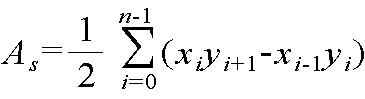
- the fluid force distribution area As may be calculated through Equation 2 below, and the fluid force distribution area is equal to the area hatched in FIG. 3.
- the center distance Ds means a distance from the origin point O to the center of mass of the fluid force distribution area As, as shown in Equation 3 below.
- Cx x-axis coordinate of the center of mass point C of a fluid force distribution area
- Cy y-axis coordinate of the center of mass point C of a fluid force distribution area
- Cx and Cy may be calculated through Equations 4 and 5, respectively.
- Equation 1 is to derive the efficiency of the high efficiency low fluid induced vibration single channel pump of the present invention, Equation 2 to Equation 5 to derive the degree of vibration of the high efficiency low fluid induced vibration single channel pump .
- step S220 of setting may be performed.
- Figure 4 is a perspective view showing a high efficiency low fluid induced vibration single channel pump designed by a method for designing a high efficiency low fluid induced vibration single channel pump according to an embodiment of the present invention
- Figure 5 is a high efficiency according to an embodiment of the present invention
- FIG. 6 is a bee designed by a method of designing a high efficiency low fluid induced vibration single channel pump according to an embodiment of the present invention. It is a perspective view which shows the internal flow path of a lute casing.
- the high efficiency low fluid induced vibration single channel pump 100 designed by the design method of the high efficiency low fluid induced vibration single channel pump 100 includes a volute casing 110 and an impeller 120.
- the volute casing 110 has a flow path space through which fluid can pass and extends in the circumferential direction.
- the volute casing 110 may have a flow path through which the fluid can pass and spirally extend in the circumferential direction, and an outlet through which the fluid may flow in and out may be formed.
- the impeller 120 is provided inside the volute casing 110 and is coupled to be rotatable for inflow and outflow of fluid.
- the impeller 120 may be installed in the inner center of the volute casing 110, the impeller 120 may be provided in a substantially cylindrical shape, it may be curved.
- the impeller 120 is connected to a drive shaft (not shown) connected to a motor (not shown), it may be provided to be rotatable by the power of the motor.
- the impeller 120 provided as described above may flow the fluid introduced during rotation using centrifugal force.
- the impeller 120 may be a bladeless impeller.
- the impeller 120 provided as described above may prevent failure and breakage caused by a clogging phenomenon when the fluid is pumped.
- the volute casing 110 of the high efficiency low fluid induced vibration single channel pump 100 provided as described above has a volute at the point where the smallest cross-sectional area of the internal flow path through which fluid flows begins.
- the angle is 0 degrees
- the volute angle at the point where the internal flow path is the largest is 360 degrees.
- the impeller 120 sets the impeller angle at the point where the smallest portion of the cross section of the internal flow path through which fluid flows is 0 degrees, and the impeller angle at the point at which the internal flow section has the largest cross section is 360 degrees.
- FIG. 7 is a graph showing design variables, design regions, and Bezier curves of a volute casing in the design method of a high efficiency low fluid induced vibration single channel pump according to an embodiment of the present invention
- FIG. 8 is an embodiment of the present invention. Is a graph showing the design parameters, design region and Bezier curve of the impeller in the design method of high efficiency low fluid induced vibration single channel pump.
- the design variables are the impeller according to the impeller angle. It includes two impeller control points that can change the cross-sectional area of the internal flow path and three volute control points that can change the cross-sectional area of the internal flow path of the volute casing according to the volute casing angle.
- the design variable consisting of two impeller control points and three volute control points may change the impeller angle and the volute control angle by changing the impeller control point and the volute control point.
- the shape of the internal flow path of the impulse volume volute designed by the internal flow path cross-sectional area changed according to the impeller angle and the volute angle may affect the target function value.
- the volute control point is a point at which a portion of the internal flow path of the volute casing 110 has the smallest cross section starts.
- the volute casing angle of is 0 degrees and the largest point can be 360 degrees.
- the volute control point is a first bee which is an arbitrary point of the horizontal axis and the vertical axis when the volute casing angle is the horizontal axis and the internal flow path cross-sectional area of the volute casing is the vertical axis, as shown in FIG. 7. It may be characterized by having a lute control point 111, the second volute control point 112 and the third volute control point 113.
- the first volute control point 111 has an internal flow path cross section of 0 to 3000 mm 2 when the volute angle is 90 degrees, and the second volute control point 112 is 180 degrees when the volute angle is 180 degrees.
- the internal flow path cross-sectional area is 0 or more and 6000 mm 2 or less, and the third volute control point 113 may have an internal flow path cross-sectional area of 3000 mm 2 or more and 6000 mm 2 or less when the volute angle is 270 degrees.
- the impeller control point the impeller angle of the point where the smallest cross-sectional area of the internal flow path of the impeller 110 starts at 0 degrees, the largest point may be 360 degrees.
- the impeller control point is a first impeller control point which is an arbitrary point between the horizontal axis and the vertical axis when the impeller angle is the horizontal axis and the internal flow path cross-sectional area of the impeller 120 is the vertical axis, as shown in FIG. 8.
- a second impeller control point 122 a first impeller control point which is an arbitrary point between the horizontal axis and the vertical axis when the impeller angle is the horizontal axis and the internal flow path cross-sectional area of the impeller 120 is the vertical axis, as shown in FIG. 8.
- a second impeller control point 122 a second impeller control point 122.
- the first impeller control point 121 has an internal flow path cross section of 130 mm 2 or more and 2330 mm 2 or less when the impeller angle is 160 degrees, and the second impeller control point 122 has an internal flow path when the impeller angle is 270 degrees.
- the cross-sectional area may be 1600 mm 2 or more and 3800 mm 2 or less.
- the design region is suddenly deteriorated by the pump function, which is the objective function, or vibrated by the fluid force distribution region and the center distance. This is determined within the range that does not grow.
- Bezier curves are one of the curve fitting methods that produce the most ideal mathematical straight lines or curves that can be represented by using realistically available data.
- a point at which an internal flow path cross-sectional area of the volute casing 110 increases is defined as the first starting point 114.
- the point where the angle of the volute casing is 360 degrees is the first end point 115, and the three volute control points 111, 112, and 113 are disposed between the first start point 114 and the first end point 115.
- the point where the internal flow path cross-sectional area of the impeller is increased is the second start point 123
- the point of the impeller angle is 360 degrees the second end point 124
- the first Bezier curve may be generated.
- two impeller control points 121 and 122 and three volute control points 111, 112, and 113 are moved only up and down, but are not limited thereto, and may be provided to move left and right. have.
- FIG. 9 is a flow chart of the step of deriving the expected objective function value in the design method of a high efficiency low fluid induced vibration single channel pump according to an embodiment of the present invention.
- Experiment Point 1 25 Internal cross section of impeller Internal flow path of the volute casing First impeller control point 2nd impeller control point First volute control point 2nd volute control point 3rd volute control point set1 713.6735 2273.469 1285.714 5397.96 5510.2041 set2 2330 2632.653 857.1429 3459.18 4714.2857 set3 1342.245 3216.327 979.5918 2948.98 3000 set4 2240.204 2004.082 2571.429 3153.06 3979.5918 set5 174.898 3485.714 673.4694 2744.9 3795.9184 set6 2195.306 3036.735 2387.755 3867.35 5632.6531 set7 1117.755 2722.449 2204.082 500 4408.1633 set8 893.2653 2497.959 2326.531 5091.84 3489.7959 set9 1656.531 1689.796 1530.612 3969.39 5081.6327
- FIG. 10 is a graph showing the cross-sectional area of the inner flow path according to the volute casing angle through the experimental point determined through the Latin hypercube sampling in the design method of the high efficiency low fluid induced vibration single channel pump according to an embodiment of the present invention
- FIG. I s a graph showing the cross-sectional area of the internal flow path according to the impeller angle through the experimental point determined through Latin hypercube sampling in the design method of the high efficiency low fluid induced vibration single channel pump according to an embodiment of the present invention.
- Table 1 and Table 2 shows the experimental points determined through the Latin hypercube sampling in a table. More specifically, Table 1 and Table 2 are the first impeller control point 121, the second impeller control point 122, the first volute control point 111, the second volute control point 112 and the third volute control point (113) is selected through Latin hypercube sampling, and a table showing the cross-sectional area of the internal flow path accordingly.
- FIGS. 10 (a) and 11 (a) are Bezier curves shown using the experimental points 1 to 25 of Table 1, and FIGS. 10 (b) and 11 (b) are shown in Table 2, respectively. It is a Bezier curve shown using experimental points 26-50.
- an optimal objective function is obtained by combining the impeller control point and the volute control point obtained through a Bezier curve.
- the expected purpose is determined through normal and abnormal analysis of the plurality of test points determined in the previous step.
- Deriving a function value may be performed (S252).
- the expected objective function value is a value obtained by calculating the objective function value of the single channel pump having the internal flow path shape of the impeller and the volute determined by the test point through the numerical analysis method described above.
- the internal flow field of the impeller and the volute casing may be a numerical analysis in the assumed state of incompressible three-dimensional normal and abnormal state.
- FIG. 12 is a three-dimensional graph showing three predicted objective function values of an experimental point in each axis in the design method of a high efficiency low fluid induced vibration single channel pump according to an embodiment of the present invention.
- the predicted objective function value calculated for each of the plurality of test points may be represented in a three-dimensional graph having pump efficiency, a center distance, and a fluid force distribution area as respective axes. And through the graph shown, by comparing the predicted objective function value of the high efficiency low fluid induced vibration single channel pump designed according to the Bezier curve generated by the test point consisting of a combination of the impeller control point and the volute control point, the impeller and The effect of the internal flow path shape of the volute casing on the objective function can be analyzed.
- the internal flow path cross-sectional area of the first impeller, the control point 121 in Figure 12 is designed for optimum 1,650mm 300mm 2 or more than 2, an internal flow path cross-sectional area of the second impeller, the control point 122 is more than 1,600mm 2 2,750mm 2 or less and , claim 1, and the internal flow path cross-sectional area of involute control point 111 is more than 0 to less than 250mm 2, the two internal flow path cross-sectional area of involute control point (112) is at least 1,250mm 2 2,400mm 2 or less, the third control point the volute ( internal cross-sectional area of the flow path 113) may be provided to less than 4,750mm 2 over 6,000mm 2.
- the pump efficiency ( ⁇ ) is 81.4% or more and 83.2% or less
- the fluid force distribution area (As) is 9,800N 2 or more and 111,400N 2 or less
- the center distance among the predicted objective functions combined with the design variables in FIG. (Ds) may be 17.4N or more and 36.8N or less.
- Figure 13 is a flow chart of the step of deriving the final purpose function value in the design method of the high efficiency low fluid induced vibration single channel pump according to an embodiment of the present invention
- Figure 14 is a high efficiency low fluid induction according to an embodiment of the present invention It is a graph of pump efficiency-fluid force distribution area, pump efficiency-center distance, and fluid force distribution area-center distance for the experimental point in the design method of the vibration single channel pump.
- the predicted objective function value derived from the experimental points located in the Bezier curve increases the pump efficiency as the fluid force distribution area is smaller and increases the pump efficiency as the center distance is larger.
- the larger the fluid force distribution area the smaller the center distance. That is, in order to increase the pump efficiency of the high efficiency low fluid induced vibration single channel pump, the fluid force distribution area should be reduced and the center distance should be increased. However, when the center distance of the fluid force increases, the vibration of the high efficiency low fluid induced vibration single channel pump increases.
- the desired pump efficiency it is possible to select an experimental point at which vibration is expected not to exceed the allowable value.
- seven first to seventh test points 131, 132, 133, 134, 135, 136, and 137 are selected for illustration.
- the comparative example in Table 3 refers to a conventional pump designed to have a constant increase in cross-sectional area of the inner flow according to the volute casing angle and the impeller angle without considering the interaction of the volute casing with the impeller.
- a step (S262) of designing a virtual pump using the selected test point as a variable may be performed.
- a step of measuring the verification objective function value of the designed virtual pump may be performed (S263). That is, in the step of measuring the verification objective function value of the designed virtual pump (S263), the pump efficiency, the fluid force distribution region, and the center distance of the designed virtual pump as the design variable of the test point may be measured.
- the verification objective function value of the virtual pump may be measured using a simulation program, or may be measured by manufacturing an actual pump.
- Table 4 is a table comparing the expected objective function value of the test point and the actual measured objective function value. That is, in the step of measuring the verification objective function value of the designed virtual pump (S263), as shown in Table 4, the pump efficiency, the fluid force distribution area, and the center distance of the designed virtual pump as the design variable of the test point are shown. Can be.
- FIG. 15 is a graph illustrating a Pareto optimal solution verification for a selected experimental point in a design method of a high efficiency low fluid induced vibration single channel pump according to an exemplary embodiment of the present invention.
- the virtual object designed as the expected objective function value of the selected experimental point and the design variable of the experimental point is selected.
- the objective value of the test which measures the objective function of the pump, is shown on the graph and can be compared by Pareto optimal solution verification.
- an expected objective function value according to the first to seventh experimental points 131, 132, 133, 134, 135, 136, and 137 and the first to seventh experimental points 131 A graph of the verification objective function according to the first to seventh measuring points 141, 142, 143, 144, 145, 146, 147 of the virtual pump designed as design variables of 132, 133, 134, 135, 136, and 137. It can be shown in the comparison and compared.
- the pump efficiency is higher than that of the first test point 131, and the center distance and the fluid force distribution area are smaller than the first test point 131. You can check it. That is, it can be seen that the virtual pump designed due to the design variable of the first experimental point 131 actually has better pump efficiency and smaller vibration than expected.
- the pump efficiency is lower than that of the fifth experimental point 135, and the center distance is larger than that of the fifth experimental point 135. That is, the virtual pump designed due to the design variable of the fifth experimental point 135 is actually lower than the expected pump efficiency, it can be seen that the vibration is large.
- the verification objective function value and the expected objective function value are compared and verified, It is possible to derive the final objective function value which has the pump efficiency but the vibration occurs below the predetermined allowable value.
- step (S260) of deriving the final objective function value by verifying the validity of the derived expected objective function value an experimental point having an expected objective function value corresponding to a target pump efficiency and an allowable vibration generation degree is obtained.
- the final objective function value with the desired pump efficiency and the vibration occurring below the preset allowable value is determined. Can be derived.
- FIG. 16 is an exemplary view showing a section pressure distribution of a high efficiency low fluid induced vibration single channel pump designed by a conventional single channel pump and a method of designing a high efficiency low fluid induced vibration single channel pump according to an embodiment of the present invention.
- FIG. 16 shows the sectional pressure distribution of a generally used single channel pump designed without considering the interaction between the impeller and the volute casing, and (b), (c), and (d), respectively, in order
- the pressure distribution of a single channel pump designed as a design variable of the first experimental point 131, the fourth experimental point 134, and the seventh experimental point 137 is illustrated.
- the single channel pump designed as a design variable of the first experimental point 131, the fourth experimental point 134, and the seventh experimental point 137 has a variation in section pressure compared to a conventional single channel pump. It can be seen that less vibration occurs due to less.
- the conventional single channel pump refers to a conventional pump designed to increase the cross-sectional area of the internal flow path in accordance with the volute casing angle and the impeller angle without considering the interaction between the volute casing and the impeller.
- a step (S270) of deriving a design proposal according to the derived final purpose function value may be performed.
- the design proposal may be a combination of design variable values for deriving the final purpose function value.
- the high efficiency low fluid induced vibration single channel pump is designed by reducing the vibration induced by the fluid force while having the target high pump efficiency. can do.
- the high efficiency low fluid induced vibration single channel pump designed as a design method of the high efficiency low fluid induced vibration single channel pump can be applied to the drainage treatment device.
Abstract
본 발명은 고효율 저유체 유발 진동 단일채널펌프의 설계방법에 관한 것으로, 보다 상세하게는 임펠러와 벌류트 케이싱의 상호작용을 고려하여 단일채널펌프를 설계함으로써, 단일채널펌프의 양정 효율을 높임과 동시에 유체력에 의해 유발되는 진동을 저감하기 위한 고효율 저유체 유발 진동 단일채널펌프의 설계방법에 관한 것이다.
Description
본 발명은 고효율 저유체 유발 진동 단일채널펌프의 설계방법에 관한 것으로, 보다 상세하게는 임펠러와 벌류트 케이싱의 상호작용을 고려하여 단일채널펌프를 설계함으로써, 단일채널펌프의 양정 효율을 높임과 동시에 유체력에 의해 유발되는 진동을 저감하기 위한 고효율 저유체 유발 진동 단일채널펌프의 설계방법에 관한 것이다.
일반적으로 오폐수 펌프는 하수, 폐수 슬러지 등을 이송하는 펌프로, 여러 산업분야에서 다양하게 사용되고 있다.
이러한 오폐수 펌프는 일반적인 수중 펌프와 달리 이물질을 포함하는 유체를 이동시켜야 하기 때문에, 유로 막힘 현상(clogging)이 자주 발생한다. 이처럼 유로 막힘 현상은 오폐수 펌프의 양정 효율 등의 성능을 감소시키거나, 오폐수 펌프의 고장 및 파손을 유발할 수 있다. 따라서, 오폐수 펌프는 막힘 현상이 발생하지 않도록 설계하는 것이 중요하다.
도 1은 종래의 보르텍스펌프 및 단일채널펌프의 내부를 나타낸 예시도이다.
도 1의 (a)는 보르텍스(vortex)펌프이다. 상기 보르텍스 펌프는 종래의 복수의 유로를 갖는 임펠러가 적용된 오폐수 펌프의 유로 막힘 현상을 방지하기 위하여 고안된 것으로써, 임펠러 길이를 짧게하여 유로를 넓게 확보하기 때문에 유로 막힘 현상이 발생하는 것을 방지하였다. 그러나, 상기 보르텍스 펌프는 임펠러의 길이가 짧아지면서 기존 오폐수 펌프에 비해 양정 효율이 30% 정도 밖에 미치지 못하는 문제점이 있다.
도 1의 (b)는 단일채널펌프다. 상기 단일채널펌프는 임펠러의 내부에 하나의 유로를 형성하고, 임펠러의 회전에 따라 유로가 함께 회전하여 오폐수를 이송하도록 마련된다. 이처럼 마련된 단일채널펌프는 유로 막힘 현상이 발생하지 않으면서도 상기 보르텍스 펌프에 비해 양정효율이 2배 이상 높다는 장점이 있다. 그러나, 상기 단일채널펌프의 임펠러는 일반적인 임펠러와 달리 비대칭구조로 이루어져 있기 때문에, 단일채널펌프를 작동시 유체력의 분포가 일정하지 않아 진동이 크게 발생한다는 문제점이 있으며, 특히, 펌프 효율을 높이려 할수록 진동이 더욱 크게 증가하여 현장에 적용이 어렵다는 문제점이 있다.
따라서, 단일채널펌프는 효율을 높이면서 유체력에 의해 유발되는 진동을 저감할 수 있는 기술이 필요하다.
(선행특허문헌) 미국등록특허 제6837684호 (2005.01.04)
상기와 같은 문제를 해결하기 위한 본 발명의 목적은 임펠러와 벌류트 케이싱의 상호작용을 고려하여 단일채널펌프를 설계함으로써, 단일채널펌프의 양정 효율을 높임과 동시에 유체력에 의해 유발되는 진동을 저감하기 위한 고효율 저유체 유발 진동 단일채널펌프의 설계방법에 관한 것이다.
본 발명이 이루고자 하는 기술적 과제는 이상에서 언급한 기술적 과제로 제한되지 않으며, 언급되지 않은 또 다른 기술적 과제들은 아래의 기재로부터 본 발명이 속하는 기술 분야에서 통상의 지식을 가진 자에게 명확하게 이해될 수 있을 것이다.
상기와 같은 목적을 달성하기 위한 본 발명의 구성은 a) 단일채널펌프의 임펠러 및 벌류트 케이싱의 형상을 고려하여 3개의 목적함수를 선정하는 단계; b) 상기 임펠러 및 벌류트 케이싱의 내부유로 단면적을 동시에 제어하여 상호작용을 분석하기 위한 설계변수를 설정하는 단계; c) 상기 설정된 설계변수의 상한값 및 하한값을 결정하여 설계영역을 지정하는 단계; d) 상기 지정된 설계영역에서 베지어 곡선을 이용하여 상기 설계변수를 조합하는 단계; e) 상기 조합된 설계변수를 이용하여 수치해석을 수행함으로써, 상기 설계변수에 따른 예상목적함수값을 도출하는 단계; f) 도출된 상기 예상목적함수값의 타당성을 검증하여 최종목적함수값을 도출하는 단계; 및 g) 도출된 상기 최종목적함수값에 따라 설계안을 도출하는 단계를 포함하는 고효율 저유체 유발 진동 단일채널펌프의 설계방법을 제공한다.
본 발명의 실시예에 있어서, 상기 a) 단계에서, 상기 목적함수는, 펌프 효율, 유체력 분포영역, 중심거리를 포함하는 것을 특징으로 할 수 있다.
본 발명의 실시예에 있어서, 상기 펌프 효율은 (여기서, η=펌프 효율, ρ=밀도, g=중력가속도, H=수두, Q=체적 유량, P=동력)인 것을 특징으로 할 수 있다.
본 발명의 실시예에 있어서, 상기 유체력 분포영역은  인 것을 특징으로 할 수 있다.
본 발명의 실시예에 있어서, 상기 중심거리인 원점부터 상기 유체력 분포영역의 질량 중심점과의 거리는,  (Cx= 유체력 분포영역의 질량 중심점의 x축 좌표, Cy=유체력 분포영역의 질량 중심점의 y축 좌표)이며, 여기서,
  ,
,  인 것을 특징으로 할 수 있다.
본 발명의 실시예에 있어서, 상기 b) 단계에서, 상기 설계변수는, 임펠러 각도에 따라 상기 임펠러의 내부유로 단면적이 변할 수 있는 2개의 임펠러 제어점; 및 벌류트 케이싱 각도에 따라 상기 벌류트 케이싱의 내부유로 단면적이 변할 수 있는 3개의 벌류트 제어점을 포함하는 것을 특징으로 할 수 있다.
본 발명의 실시예에 있어서, 상기 c) 단계에서, 상기 임펠러 제어점은, 상기 임펠러의 내부유로 단면적이 가장 작은 부분이 시작하는 지점의 임펠러 각도는 0도로 하고, 가장 큰 지점을 360도로 하며, 상기 임펠러 각도를 가로축으로 하고, 상기 임펠러의 내부유로 단면적을 세로축으로 할 때, 상기 가로축과 상기 세로축의 임의의 점인 제1 임펠러 제어점 및 제2 임펠러 제어점을 갖는 것을 특징으로 할 수 있다.
본 발명의 실시예에 있어서, 상기 제1 임펠러 제어점은 상기 임펠러 각도가 160도일 때 내부유로 단면적이 130 mm2 이상 2330 mm2 이하이고, 상기 제2 임펠러 제어점은 상기 임펠러 각도가 270도일 때 내부유로 단면적이 1600 mm2 이상 3800 mm2 이하인 것을 특징으로 할 수 있다.
본 발명의 실시예에 있어서, 상기 벌류트 제어점은, 상기 벌류트 케이싱의 내부유로 단면적이 가장 작은 부분이 시작하는 지점의 벌류트 케이싱 각도는 0도로 하고, 가장 큰 지점을 360도로 하며, 상기 벌류트 케이싱 각도를 가로축으로 하고, 상기 벌류트 케이싱의 내부유로 단면적을 세로축으로 할 때, 상기 가로축과 상기 세로축의 임의의 점인 제1 벌류트 제어점, 제2 벌류트 제어점 및 제3 벌류트 제어점을 갖는 것을 특징으로 할 수 있다.
본 발명의 실시예에 있어서, 상기 제1 벌류트 제어점은 상기 벌류트 각도가 90도일 때 내부유로 단면적이 0이상 3000 mm2 이하이고, 상기 제2 벌류트 제어점은 상기 벌류트 각도가 180도일 때 내부유로 단면적이 0이상 6000 mm2 이하이며, 상기 제3 벌류트 제어점은 상기 벌류트 각도가 270도일 때, 내부유로 단면적이 3000 mm2 이상 6000 mm2 이하인 것을 특징으로 할 수 있다.
본 발명의 실시예에 있어서, 상기 d) 단계는, 상기 임펠러의 내부 유로 단면적이 증가하는 지점을 제2 개시점으로 하고, 상기 임펠러 각도가 360도인 지점은 제2 종료점으로 하며, 상기 제2 개시점과 상기 제2 종료점 사이에서 2개의 상기 임펠러 제어점이 변할 때 상기 제2 개시점, 상기 제2 종료점 및 상기 2개의 제어점으로 표현된 제1 베지어 곡선을 생성하는 것을 특징으로 할 수 있다.
본 발명의 실시예에 있어서, 상기 d) 단계는, 상기 벌류트 케이싱의 내부 유로 단면적이 증가하는 지점을 제1 개시점으로 하고, 상기 벌류트 케이싱의 각도가 360도인 지점은 제1 종료점으로 하며, 상기 제1 개시점과 상기 제1 종료점 사이에서 3개의 상기 벌류트 제어점이 변할 때 상기 제1 개시점, 상기 제1 종료점 및 상기 3개의 벌류트 제어점으로 표현된 제2 베지어 곡선을 생성하는 것을 특징으로 할 수 있다.
본 발명의 실시예에 있어서, 상기 e) 단계는, e1) 상기 설계영역에서 라틴 하이퍼 큐브 샘플링(LHS)을 통해 상기 설계변수로 이루어진 복수개의 실험점을 결정하는 단계; 및 e2) 결정된 복수개의 상기 실험점에 대한 정상 및 비정상 해석을 통해 상기 예상목적함수값을 도출하는 단계를 포함하는 것을 특징으로 할 수 있다.
본 발명의 실시예에 있어서, 상기 e2) 단계 이후에, e3) 도출된 상기 예상목적함수값을 변수로 한 3차원 파레토 최적해를 이용하여 상기 임펠러와 상기 벌류트 케이싱의 내부 유로 형상이 목적함수에 미치는 영향을 분석하는 단계를 더 포함하는 것을 특징으로 할 수 있다.
본 발명의 실시예에 있어서, 상기 f) 단계는, f1) 상기 복수개의 실험점 중 임의의 실험점을 선택하는 단계; f2) 선택된 상기 실험점을 변수로 한 가상펌프를 설계하는 단계; f3) 설계된 상기 가상펌프의 상기 검증목적함수값을 측정하는 단계; 및 f4) 측정된 상기 검증목적함수값과 상기 예상목적함수값을 비교하여 검증함으로써, 상기 최종목적함수값을 도출하는 단계를 포함하는 것을 특징으로 할 수 있다.
본 발명의 실시예에 있어서, 상기 g) 단계에서, 상기 설계안은 상기 최종목적함수값이 도출되도록 하는 상기 설계변수 값의 조합인 것을 특징으로 할 수 있다.
상기와 같은 목적을 달성하기 위한 본 발명의 구성은 고효율 저유체 유발 진동 단일채널펌프의 설계방법에 의하여 설계된 고효율 저유체 유발 진동 단일채널펌프를 제공한다.
상기와 같은 목적을 달성하기 위한 본 발명의 구성은 고효율 저유체 유발 진동 단일채널펌프의 설계방법으로 설계된 고효율 저유체 유발 진동 단일채널펌프를 적용한 배수 처리 장치를 제공한다.
상기와 같은 구성에 따르는 본 발명의 효과는, 분뇨, 오폐수, 오물, 및 고형물과 같이 점도가 있는 슬러지를 막힘 현상 없이 펌핑하여 단일채널펌프의 고장 및 파손을 방지하고 높은 양정 효율을 갖는다.
또한, 본 발명에 따르면, 임펠러와 벌류트 케이싱의 상호작용을 분석하여 단일채널펌프를 설계함으로써, 단일채널펌프가 높은 효율을 갖되, 유체력에 의해 유발되는 진동이 최소화되도록 설계될 수 있다.
본 발명의 효과는 상기한 효과로 한정되는 것은 아니며, 본 발명의 상세한 설명 또는 특허청구범위에 기재된 발명의 구성으로부터 추론 가능한 모든 효과를 포함하는 것으로 이해되어야 한다.
도 1은 종래의 보르텍스펌프 및 단일채널펌프의 내부를 나타낸 예시도이다.
도 2는 본 발명의 일실시예에 따른 고효율 저유체 유발 진동 단일채널펌프의 설계방법의 순서도이다.
도 3은 본 발명의 일실시예에 따른 고효율 저유체 유발 진동 단일채널펌프의 설계방법에서 1회전 동안의 유체력의 분포도를 나타낸 예시도이다.
도 4는 본 발명의 일실시예에 따른 고효율 저유체 유발 진동 단일채널펌프의 설계방법에 의해 설계된 고효율 저유체 유발 진동 단일채널펌프를 나타낸 사시도이다.
도 5는 본 발명의 일실시예에 따른 고효율 저유체 유발 진동 단일채널펌프의 설계방법에 의해 설계된 임펠러의 내부유로 통로를 도시한 사시도이다.
도 6은 본 발명의 일실시예에 따른 고효율 저유체 유발 진동 단일채널펌프의 설계방법에 의해 설계된 벌류트 케이싱의 내부유로 통로를 도시한 사시도이다.
도 7은 본 발명의 일실시예에 따른 고효율 저유체 유발 진동 단일채널펌프의 설계방법에서 벌류트 케이싱의 설계변수, 설계영역 및 베지어 곡선을 나타낸 그래프이다.
도 8은 본 발명의 일실시예에 따른 고효율 저유체 유발 진동 단일채널펌프의 설계방법에서 임펠러의 설계변수, 설계영역 및 베지어 곡선을 나타낸 그래프이다.
도 9는 본 발명의 일실시예에 따른 고효율 저유체 유발 진동 단일채널펌프의 설계방법에서 예상목적함수 값을 도출하는 단계의 순서도이다.
도 10은 본 발명의 일실시예에 따른 고효율 저유체 유발 진동 단일채널펌프의 설계방법에서 라틴 하이퍼 큐브 샘플링을 통해 결정된 실험점을 통해 벌류트 케이싱 각도에 따른 내부유로 단면적을 나타낸 그래프이다.
도 11은 본 발명의 일실시예에 따른 고효율 저유체 유발 진동 단일채널펌프의 설계방법에서 라틴 하이퍼 큐브 샘플링을 통해 결정된 실험점을 통해 임펠러 각도에 따른 내부유로 단면적을 나타낸 그래프이다.
도 12는 본 발명의 일실시예에 따른 고효율 저유체 유발 진동 단일채널펌프의 설계방법에서 실험점의 3개의 예상목적함수값을 각 축으로하여 나타낸 3차원 그래프이다.
도 13은 본 발명의 일실시예에 따른 고효율 저유체 유발 진동 단일채널펌프의 설계방법에서 최종목적함수 값을 도출하는 단계의 순서도이다.
도 14는 본 발명의 일실시예에 따른 고효율 저유체 유발 진동 단일채널펌프의 설계방법에서 실험점에 대한 펌프효율-유체력 분포영역, 펌프효율-중심거리, 유체력 분포영역-중심거리의 그래프이다.
도 15는 본 발명의 일실시예에 따른 고효율 저유체 유발 진동 단일채널펌프의 설계방법에서 선택된 실험점에 대한 파레토 최적해 검증을 실시한 그래프이다.
도 16은 종래의 단일채널펌프와 본 발명의 일실시예에 따른 고효율 저유체 유발 진동 단일채널펌프의 설계방법에 의해 설계된 고효율 저유체 유발 진동 단일채널펌프의 구간 압력 분포를 나타낸 예시도이다.
본 발명의 일실시예에 따르면, a) 단일채널펌프의 임펠러 및 벌류트 케이싱의 형상을 고려하여 3개의 목적함수를 선정하는 단계; b) 상기 임펠러 및 벌류트 케이싱의 내부유로 단면적을 동시에 제어하여 상호작용을 분석하기 위한 설계변수를 설정하는 단계; c) 상기 설정된 설계변수의 상한값 및 하한값을 결정하여 설계영역을 지정하는 단계; d) 상기 지정된 설계영역에서 베지어 곡선을 이용하여 상기 설계변수를 조합하는 단계; e) 상기 조합된 설계변수를 이용하여 수치해석을 수행함으로써, 상기 설계변수에 따른 예상목적함수값을 도출하는 단계; f) 도출된 상기 예상목적함수값의 타당성을 검증하여 최종목적함수값을 도출하는 단계; 및 g) 도출된 상기 최종목적함수값에 따라 설계안을 도출하는 단계를 포함하는 고효율 저유체 유발 진동 단일채널펌프의 설계방법을 제공한다.
이하에서는 첨부한 도면을 참조하여 본 발명을 설명하기로 한다. 그러나 본 발명은 여러 가지 상이한 형태로 구현될 수 있으며, 따라서 여기에서 설명하는 실시예로 한정되는 것은 아니다. 그리고 도면에서 본 발명을 명확하게 설명하기 위해서 설명과 관계없는 부분은 생략하였으며, 명세서 전체를 통하여 유사한 부분에 대해서는 유사한 도면 부호를 붙였다.
명세서 전체에서, 어떤 부분이 다른 부분과 "연결(접속, 접촉, 결합)"되어 있다고 할 때, 이는 "직접적으로 연결"되어 있는 경우뿐 아니라, 그 중간에 다른 부재를 사이에 두고 "간접적으로 연결"되어 있는 경우도 포함한다. 또한 어떤 부분이 어떤 구성요소를 "포함"한다고 할 때, 이는 특별히 반대되는 기재가 없는 한 다른 구성요소를 제외하는 것이 아니라 다른 구성요소를 더 구비할 수 있다는 것을 의미한다.
본 명세서에서 사용한 용어는 단지 특정한 실시예를 설명하기 위해 사용된 것으로, 본 발명을 한정하려는 의도가 아니다. 단수의 표현은 문맥상 명백하게 다르게 뜻하지 않는 한, 복수의 표현을 포함한다. 본 명세서에서, "포함하다" 또는 "가지다" 등의 용어는 명세서상에 기재된 특징, 숫자, 단계, 동작, 구성요소, 부품 또는 이들을 조합한 것이 존재함을 지정하려는 것이지, 하나 또는 그 이상의 다른 특징들이나 숫자, 단계, 동작, 구성요소, 부품 또는 이들을 조합한 것들의 존재 또는 부가 가능성을 미리 배제하지 않는 것으로 이해되어야 한다.
이하 첨부된 도면을 참고하여 본 발명의 실시예를 상세히 설명하기로 한다.
도 2는 본 발명의 일실시예에 따른 고효율 저유체 유발 진동 단일채널펌프의 설계방법의 순서도이고, 도 3은 본 발명의 일실시예에 따른 고효율 저유체 유발 진동 단일채널펌프의 설계방법에서 1회전 동안의 유체력의 분포도를 나타낸 예시도이다.
도 2에 도시된 바와 같이, 고효율 저유체 유발 진동 단일채널펌프의 설계방법은 먼저, 단일채널펌프의 임펠러 및 벌류트 케이싱의 형상을 고려하여 3개의 목적함수를 선정하는 단계(S210)을 수행할 수 있다.
단일채널펌프의 임펠러 및 벌류트 케이싱의 형상을 고려하여 3개의 목적함수를 선정하는 단계(S210)에서, 상기 목적함수는, 단일채널펌프를 설계할 때 요구되는 설계 사양인 펌프 효율, 유체력 분포영역, 중심거리이다.
상기 펌프 효율은 하기의 수학식1과 같다.

여기서, η=펌프 효율, ρ=밀도, g=중력가속도, H=수두, Q=체적 유량, P=동력이다.
상기 유체력 분포영역(As)은 하기의 수학식2를 통해 연산될 수 있으며, 유체력 분포영역은 도 3에 해칭된 면적과 동일하다.

상기 중심거리(Ds)는 도 3에 도시된 바와 같이, 원점(O)부터 상기 유체력 분포영역(As)의 질량 중심점까지의 거리를 의미하며, 하기의 수학식3과 같다.
여기서, Cx=유체력 분포영역의 질량 중심점(C)의 x축 좌표, Cy=유체력 분포영역의 질량 중심점(C)의 y축 좌표이다.
그리고, Cx 및 Cy는 각각 하기의 수학식4 및 수학식5를 통해 계산될 수 있다.


상술한 수학식1은 본 발명인 고효율 저유체 유발 진동 단일채널펌프의 효율을 도출하도록 하며, 수학식 2 내지 수학식 5는 고효율 저유체 유발 진동 단일채널펌프의 진동의 발생 정도를 도출할 수 있도록 한다.
상기 단일채널펌프의 임펠러 및 벌류트 케이싱의 형상을 고려하여 3개의 목적함수를 선정하는 단계(S210) 이후에는, 임펠러 및 벌류트 케이싱의 내부유로 단면적을 동시에 제어하여 상호작용을 분석하기 위한 설계변수를 설정하는 단계(S220)를 수행할 수 있다.
임펠러 및 벌류트 케이싱의 내부유로 단면적을 동시에 제어하여 상호작용을 분석하기 위한 설계변수를 설정하는 단계(S220)를 구체적으로 설명하기 전에 먼저 하기 도면을 참조하여 고효율 저유체 유발 진동 단일채널펌프(100)에 대해 설명하도록 한다.
도 4는 본 발명의 일실시예에 따른 고효율 저유체 유발 진동 단일채널펌프의 설계방법에 의해 설계된 고효율 저유체 유발 진동 단일채널펌프를 나타낸 사시도이고, 도 5는 본 발명의 일실시예에 따른 고효율 저유체 유발 진동 단일채널펌프의 설계방법에 의해 설계된 임펠러의 내부유로 통로를 도시한 사시도이며, 도 6은 본 발명의 일실시예에 따른 고효율 저유체 유발 진동 단일채널펌프의 설계방법에 의해 설계된 벌류트 케이싱의 내부유로 통로를 도시한 사시도이다.
도 4 내지 도 6을 참조하면, 고효율 저유체 유발 진동 단일채널펌프의 설계방법에 의해 설계된 고효율 저유체 유발 진동 단일채널펌프(100)는 벌류트 케이싱(110)과 임펠러(120)를 포함한다.
상기 벌류트 케이싱(110)은 유체가 통과할 수 있는 유로 공간이 원주 방향으로 연장 형성된다. 구체적으로, 상기 벌류트 케이싱(110)은 유체가 통과할 수 있는 유로가 원주 방향으로 나선형으로 연장 형성될 수 있으며, 내부에 유체가 유입 및 배출될 수 있는 출구가 형성될 수 있다.
상기 임펠러(120)는 상기 벌류트 케이싱(110)의 내측에 마련되되, 유체의 유입 및 배출을 위해 회전 가능하도록 결합된다. 구체적으로, 상기 임펠러(120)는 상기 벌류트 케이싱(110)의 내부 중심에 설치될 수 있으며, 상기 임펠러(120)는 대체적으로 원통 형상으로 마련될 수 있으며, 만곡 형성될 수 있다. 그리고, 도시하지는 않았으나, 상기 임펠러(120)는 모터(미도시)와 연결된 구동축(미도시)과 연결되며, 상기 모터의 동력에 의해 회전 가능하도록 마련될 수 있다. 이처럼 마련된 상기 임펠러(120)는 회전시 유입되는 유체를 원심력을 이용하여 유동시킬 수 있다.
또한, 상기 임펠러(120)는 블레이드리스(Bladeless) 임펠러일 수 있다. 이처럼 마련된 상기 임펠러(120)는 유체를 펌핑할 때, 막힘 현상으로 인해 유발되는 고장 및 파손을 방지할 수 있다.
설명의 편의를 위해, 전술한 바와 같이 마련된 고효율 저유체 유발 진동 단일채널펌프(100)의 벌류트 케이싱(110)은 유체가 유동되는 내부유로 단면적 중 가장 작은 단면적인 곳이 시작하는 지점의 벌류트 각도를 0도로 하고, 내부유로 단면적이 가장 큰 지점의 벌류트 각도를 360도로 한다.
또한, 상기 임펠러(120)는 유체가 유동되는 내부유로 단면적 중 가장 작은 부분이 시작되는 지점의 임펠러 각도를 0도로 하고, 내부유로 단면적이 가장 큰 지점의 임펠러 각도를 360도로 한다.
도 7은 본 발명의 일실시예에 따른 고효율 저유체 유발 진동 단일채널펌프의 설계방법에서 벌류트 케이싱의 설계변수, 설계영역 및 베지어 곡선을 나타낸 그래프이고, 도 8은 본 발명의 일실시예에 따른 고효율 저유체 유발 진동 단일채널펌프의 설계방법에서 임펠러의 설계변수, 설계영역 및 베지어 곡선을 나타낸 그래프이다.
도 7 및 도 8을 더 참조하면, 임펠러 및 벌류트 케이싱의 내부유로 단면적을 동시에 제어하여 상호작용을 분석하기 위한 설계변수를 설정하는 단계(S220)에서 상기 설계변수는, 임펠러 각도에 따라 상기 임펠러의 내부유로 단면적이 변할 수 있는 2개의 임펠러 제어점 및 벌류트 케이싱 각도에 따라 상기 벌류트 케이싱의 내부유로 단면적이 변할 수 있는 3개의 벌류트 제어점을 포함한다.
보다 구체적으로, 2개의 임펠러 제어점과 3개의 벌류트 제어점으로 이루어진 설계변수는, 각 임펠러 제어점과 벌류트 제어점을 변화시킴으로써, 임펠러 각도 및 벌류트 각도에 따른 내부 유로 단면적이 변화되도록 할 수 있다. 그리고, 임펠러 각도 및 벌류트 각도에 따라 변화한 내부 유로 단면적에 의해 설계된 임펄롸 벌류트의 내부 유로 형상은 상기 목적함수값에 영향을 미칠 수 있다.
임펠러 및 벌류트 케이싱의 내부유로 단면적을 동시에 제어하여 상호작용을 분석하기 위한 설계변수를 설정하는 단계(S220) 이후에는, 상기 설정된 설계변수의 상한값 및 하한값을 결정하여 설계영역을 지정하는 단계(S230)를 수행할 수 있다.
구체적으로, 상기 설정된 설계변수의 상한값 및 하한값을 결정하여 설계영역을 지정하는 단계(S230)에서, 상기 벌류트 제어점은, 상기 벌류트 케이싱(110)의 내부유로 단면적이 가장 작은 부분이 시작하는 지점의 벌류트 케이싱 각도는 0도로 하고, 가장 큰 지점을 360도로 할 수 있다. 그리고, 상기 벌류트 제어점은, 도 7에 도시된 것처럼 상기 벌류트 케이싱 각도를 가로축으로 하고, 상기 벌류트 케이싱의 내부유로 단면적을 세로축으로 할 때, 상기 가로축과 상기 세로축의 임의의 점인 제1 벌류트 제어점(111), 제2 벌류트 제어점(112) 및 제3 벌류트 제어점(113)을 갖는 것을 특징으로 할 수 있다.
그리고, 상기 제1 벌류트 제어점(111)은 상기 벌류트 각도가 90도일 때 내부유로 단면적이 0이상 3000 mm2 이하이고, 상기 제2 벌류트 제어점(112)은 상기 벌류트 각도가 180도일 때 내부유로 단면적이 0이상 6000 mm2 이하이며, 상기 제3 벌류트 제어점(113)은 상기 벌류트 각도가 270도일 때, 내부유로 단면적이 3000 mm2 이상 6000 mm2 이하인 것을 특징으로 할 수 있다.
또한, 상기 임펠러 제어점은, 상기 임펠러(110)의 내부유로 단면적이 가장 작은 부분이 시작하는 지점의 임펠러 각도는 0도로 하고, 가장 큰 지점을 360도로 할 수 있다. 그리고, 상기 임펠러 제어점은, 도 8에 도시된 것처럼, 상기 임펠러 각도를 가로축으로 하고, 상기 임펠러(120)의 내부유로 단면적을 세로축으로 할 때, 상기 가로축과 상기 세로축의 임의의 점인 제1 임펠러 제어점(121) 및 제2 임펠러 제어점(122)을 갖는 것을 특징으로 할 수 있다.
그리고, 상기 제1 임펠러 제어점(121)은 상기 임펠러 각도가 160도일 때 내부유로 단면적이 130 mm2 이상 2330 mm2 이하이고, 상기 제2 임펠러 제어점(122)은 상기 임펠러 각도가 270도일 때 내부유로 단면적이 1600 mm2 이상 3800 mm2 이하인 것을 특징으로 할 수 있다.
상기 설정된 설계변수의 상한값 및 하한값을 결정하여 설계영역을 지정하는 단계(S230)에서 상기 설계영역은 선행 계산을 통해서 목적함수인 펌프 효율이 급격하게 저하되거나, 유체력 분포영역 및 중심 거리에 의해 진동이 커지지 않는 범위 내로 결정된 것이다.
상기 설정된 설계변수의 상한값 및 하한값을 결정하여 설계영역을 지정하는 단계(S230) 이후에는, 지정된 설계영역에서 베지어 곡선을 이용하여 설계변수를 조합하는 단계(S240)를 수행할 수 있다.
베지어 곡선(Bezier curve)은 현실적으로 얻을 수 있는 데이터를 이용하여 그 데이터들로 표현할 수 있는 가장 이상적인 수학적인 직선 혹은 곡선을 얻어내는 커브 피팅(Curve fitting) 방법 중 하나이다.
구체적으로, 지정된 설계영역에서 베지어 곡선을 이용하여 설계변수를 조합하는 단계(S240)는 상기 벌류트 케이싱(110)의 내부 유로 단면적이 증가하는 지점을 제1 개시점(114)으로 하고, 상기 벌류트 케이싱의 각도가 360도인 지점은 제1 종료점(115)으로 하며, 상기 제1 개시점(114)과 상기 제1 종료점(115) 사이에서 3개의 상기 벌류트 제어점(111, 112, 113)이 변할 때 상기 제1 개시점(114), 상기 제1 종료점(115) 및 상기 3개의 벌류트 제어점(111, 112, 113)으로 표현된 제2 베지어 곡선을 생성하는 것을 특징으로 할 수 있다.
또한, 상기 임펠러의 내부 유로 단면적이 증가하는 지점을 제2 개시점(123)으로 하고, 상기 임펠러 각도가 360도인 지점은 제2 종료점(124)으로 하며, 상기 제2 개시점(123)과 상기 제2 종료점(124) 사이에서 2개의 상기 임펠러 제어점(121, 122)이 변할 때 상기 제2 개시점(123), 상기 제2 종료점(124) 및 상기 2개의 제어점(121, 122)으로 표현된 제1 베지어 곡선을 생성하는 것을 특징으로 할 수 있다.
단, 본 발명의 일실시예에서는 2개의 임펠러 제어점(121, 122)과 3개의 벌류트 제어점(111, 112, 113)이 상하로만 이동되도록 하였으나, 이에 한정되지 않고, 좌우로 이동되도록 마련될 수도 있다.
지정된 설계영역에서 베지어 곡선을 이용하여 설계변수를 조합하는 단계(S240) 이후에는, 조합된 설계변수를 이용하여 수치해석을 수행함으로써, 설계변수에 따른 예상목적함수값을 도출하는 단계(S250)를 수행할 수 있다.
도 9는 본 발명의 일실시예에 따른 고효율 저유체 유발 진동 단일채널펌프의 설계방법에서 예상목적함수 값을 도출하는 단계의 순서도이다.
도 9를 더 참조하면, 조합된 설계변수를 이용하여 수치해석을 수행함으로써, 설계변수에 따른 예상목적함수값을 도출하는 단계(S250)는 먼저, 설계영역에서 라틴 하이퍼 큐브 샘플링(LHS)을 통해 상기 설계변수로 이루어진 복수개의 실험점을 결정하는 단계(S251)를 수행할 수 있다.
| 실험점1~25 | 임펠러 내부유로 단면적 | 벌류트 케이싱 내부유로 단면적 | |||
| 제1 임펠러 제어점 | 제2 임펠러 제어점 | 제1 벌류트 제어점 | 제2 벌류트 제어점 | 제3 벌류트제어점 | |
| set1 | 713.6735 | 2273.469 | 1285.714 | 5397.96 | 5510.2041 |
| set2 | 2330 | 2632.653 | 857.1429 | 3459.18 | 4714.2857 |
| set3 | 1342.245 | 3216.327 | 979.5918 | 2948.98 | 3000 |
| set4 | 2240.204 | 2004.082 | 2571.429 | 3153.06 | 3979.5918 |
| set5 | 174.898 | 3485.714 | 673.4694 | 2744.9 | 3795.9184 |
| set6 | 2195.306 | 3036.735 | 2387.755 | 3867.35 | 5632.6531 |
| set7 | 1117.755 | 2722.449 | 2204.082 | 500 | 4408.1633 |
| set8 | 893.2653 | 2497.959 | 2326.531 | 5091.84 | 3489.7959 |
| set9 | 1656.531 | 1689.796 | 1530.612 | 3969.39 | 5081.6327 |
| set10 | 1521.837 | 3530.612 | 367.3469 | 4173.47 | 4897.9592 |
| set11 | 1881.02 | 3171.429 | 1775.51 | 806.122 | 3244.898 |
| set12 | 1387.143 | 2183.673 | 3000 | 2438.78 | 5142.8571 |
| set13 | 2015.714 | 2138.776 | 183.6735 | 1418.37 | 5693.8776 |
| set14 | 2150.408 | 3126.531 | 1346.939 | 1112.24 | 5326.5306 |
| set15 | 983.0612 | 3710.204 | 1653.061 | 1826.53 | 4224.4898 |
| set16 | 668.7755 | 3620.408 | 2938.776 | 4275.51 | 3734.6939 |
| set17 | 534.0816 | 1600 | 551.0204 | 3255.1 | 5265.3061 |
| set18 | 803.4694 | 1644.898 | 2632.653 | 4785.71 | 4653.0612 |
| set19 | 1970.816 | 1734.694 | 1897.959 | 1214.29 | 5020.4082 |
| set20 | 848.3673 | 2542.857 | 61.22449 | 3051.02 | 3918.3674 |
| set21 | 2060.612 | 3755.102 | 734.6939 | 2132.65 | 4102.0408 |
| set22 | 1162.653 | 3665.306 | 2020.408 | 4683.67 | 5448.9796 |
| set23 | 1072.857 | 3351.02 | 0 | 1622.45 | 4836.7347 |
| set24 | 2105.51 | 2857.143 | 2081.633 | 5193.88 | 4040.8163 |
| set25 | 1925.918 | 3440.816 | 2755.102 | 2030.61 | 4469.3878 |
| 실험점26~50 | 임펠러 내부유로 단면적 | 벌류트 케이싱 내부유로 단면적 | |||
| 제1 임펠러제어점 | 제2 임펠러 제어점 | 제1 벌류트 제어점 | 제2 벌류트 제어점 | 제3 벌류트제어점 | |
| set26 | 1701.429 | 1914.286 | 1102.04082 | 3765.30612 | 3428.571 |
| set27 | 444.2857 | 1779.592 | 1959.18367 | 908.163265 | 4775.51 |
| set28 | 1746.327 | 2902.041 | 2693.87755 | 3561.22449 | 3061.224 |
| set29 | 758.5714 | 3306.122 | 2877.55102 | 1928.57143 | 5387.755 |
| set30 | 623.8776 | 2318.367 | 795.918367 | 704.081633 | 3306.122 |
| set31 | 264.6939 | 2228.571 | 918.367347 | 4887.7551 | 3612.245 |
| set32 | 1791.224 | 2677.551 | 122.44898 | 1316.32653 | 3551.02 |
| set33 | 354.4898 | 2991.837 | 428.571429 | 3663.26531 | 5571.429 |
| set34 | 1611.633 | 3800 | 1836.73469 | 4377.55102 | 3857.143 |
| set35 | 2285.102 | 3261.224 | 306.122449 | 4581.63265 | 3367.347 |
| set36 | 1836.122 | 1869.388 | 1469.38776 | 1010.20408 | 3183.673 |
| set37 | 1476.939 | 2363.265 | 244.897959 | 4071.42857 | 5755.102 |
| set38 | 130 | 2453.061 | 1408.16327 | 2642.85714 | 4346.939 |
| set39 | 1432.041 | 2587.755 | 489.795918 | 5500 | 4163.265 |
| set40 | 1207.551 | 2408.163 | 1591.83673 | 1724.4898 | 5816.327 |
| set41 | 938.1633 | 1959.184 | 2265.30612 | 2540.81633 | 3673.469 |
| set42 | 1252.449 | 2767.347 | 1714.28571 | 3357.14286 | 4530.612 |
| set43 | 1027.959 | 3575.51 | 1224.4898 | 2234.69388 | 6000 |
| set44 | 578.9796 | 3395.918 | 1040.81633 | 5295.91837 | 4285.714 |
| set45 | 1566.735 | 2093.878 | 2816.32653 | 4989.79592 | 5938.776 |
| set46 | 219.7959 | 2812.245 | 2510.20408 | 4479.59184 | 4959.184 |
| set47 | 399.3878 | 2946.939 | 1163.26531 | 602.040816 | 5204.082 |
| set48 | 489.1837 | 3081.633 | 2142.85714 | 2336.73469 | 3122.449 |
| set49 | 309.5918 | 2048.98 | 2448.97959 | 2846.93878 | 5877.551 |
| set50 | 1297.347 | 1824.49 | 612.244898 | 1520.40816 | 4591.837 |
도 10은 본 발명의 일실시예에 따른 고효율 저유체 유발 진동 단일채널펌프의 설계방법에서 라틴 하이퍼 큐브 샘플링을 통해 결정된 실험점을 통해 벌류트 케이싱 각도에 따른 내부유로 단면적을 나타낸 그래프이고, 도 11은 본 발명의 일실시예에 따른 고효율 저유체 유발 진동 단일채널펌프의 설계방법에서 라틴 하이퍼 큐브 샘플링을 통해 결정된 실험점을 통해 임펠러 각도에 따른 내부유로 단면적을 나타낸 그래프이다.
그리고, 표 1 및 표 2는 라틴 하이퍼 큐브 샘플링을 통해 결정된 실험점을 표로 나타낸 것이다. 보다 구체적으로, 상기 표 1 및 표 2는 제1 임펠러 제어점(121), 제2 임펠러 제어점(122), 제1 벌류트 제어점(111), 제2 벌류트 제어점(112) 및 제3 벌류트 제어점(113)을 라틴 하이퍼 큐브 샘플링을 통해 선정하고, 이에 따른 내부유로 단면적을 나타낸 표이다.
또한, 도 10의 (a) 및 도 11의 (a)는 표 1의 실험점 1 내지 25를 이용하여 나타낸 베지어곡선이며, 도 10의 (b) 및 도 11의 (b)는 표 2의 실험점 26 내지 50을 이용하여 나타낸 베지어곡선이다.
설계영역에서 라틴 하이퍼 큐브 샘플링(LHS)을 통해 상기 설계변수로 이루어진 복수개의 실험점을 결정하는 단계(S251)에서는 베지어 곡선을 통해 구한 상기 임펠러 제어점 및 상기 벌류트 제어점을 조합하여 최적의 목적함수 값을 계산할 복수개의 실험점을 결정한다. 도 10 및 도 11에 도시된 그래프는 라틴 하이퍼 큐브 샘플링을 통해 결정된 실험점을 이용하여 나타낸 복수의 베지어곡선을 확인할 수 있다. 이러한 베지어곡선은 모두 설계 영역 내에 위치함을 확인할 수 있다.
설계영역에서 라틴 하이퍼 큐브 샘플링(LHS)을 통해 상기 설계변수로 이루어진 복수개의 실험점을 결정하는 단계(S251) 이후에는, 이전 단계에서 결정된 복수개의 실험점에 대한 정상 및 비정상 해석을 통해 상기 예상목적함수값을 도출하는 단계(S252)를 수행할 수 있다. 여기서, 예상목적함수값은 전술한 수치해석 방법을 통해 상기 실험점에 의해 정해진 임펠러와 벌류트의 내부 유로 형상을 갖는 단일채널펌프의 목적함수값을 계산한 값이다. 그리고 이때, 상기 임펠러 및 상기 벌류트 케이싱의 내부 유동장은 비압축성 3차원 정상 및 비정상상태로 가정된 상태에서 수치해석이 이루어질 수 있다.
도 12는 본 발명의 일실시예에 따른 고효율 저유체 유발 진동 단일채널펌프의 설계방법에서 실험점의 3개의 예상목적함수값을 각 축으로하여 나타낸 3차원 그래프이다.
결정된 복수개의 실험점에 대한 정상 및 비정상 해석을 통해 상기 예상목적함수값을 도출하는 단계(S252) 이후에는, 도출된 예상목적함수값을 변수로 한 3차원 파레토 최적해를 이용하여 임펠러와 벌류트 케이싱의 내부 유로 형상이 목적함수에 미치는 영향을 분석하는 단계(S253)를 더 수행할 수 있다.
구체적으로, 도출된 예상목적함수값을 변수로 한 3차원 파레토 최적해를 이용하여 임펠러와 벌류트 케이싱의 내부 유로 형상이 목적함수에 미치는 영향을 분석하는 단계(S253)에서는 도 12에 도시된 것처럼, 펌프효율, 중심거리, 유체력분포영역을 각각의 축으로 하는 3차원 그래프에 복수의 상기 실험점에 대해 각각 계산한 상기 예상목적함수값을 나타낼 수 있다. 그리고 도시된 그래프를 통해서, 임펠러 제어점과 벌류트 제어점의 조합으로 이루어진 상기 실험점에 의해 생성된 베지어곡선에 따라 설계된 고효율 저유체 유발 진동 단일채널펌프의 예상목적함수값을 상호 비교하여, 임펠러와 벌류트 케이싱의 내부 유로 형상이 목적함수에 미치는 영향을 분석할 수 있다.
이때, 최적 설계된 도 12에서의 제1 임펠러 제어점(121)의 내부유로 단면적은 300mm2 이상1,650mm2 이하이고, 제2 임펠러 제어점(122)의 내부유로 단면적은 1,600mm2 이상 2,750mm2 이하이며, 제1 벌류트 제어점(111)의 내부유로 단면적은 0 초과250mm2 이하이고, 제2 벌류트 제어점(112)의 내부유로 단면적은 1,250mm2 이상2,400mm2 이하이며, 제3 벌류트 제어점(113)의 내부유로 단면적은 4,750mm2 이상6,000mm2 이하로 마련될 수 있다.
그리고, 도 12에서의 설계변수로 조합된 예상목적함수값 중 펌프 효율(η)은 81.4% 이상 83.2% 이하이고, 유체력 분포영역(As)은 9,800N2 이상 111,400N2 이하이며, 중심거리(Ds)는 17.4N 이상 36.8N 이하일 수 있다.
도 13은 본 발명의 일실시예에 따른 고효율 저유체 유발 진동 단일채널펌프의 설계방법에서 최종목적함수 값을 도출하는 단계의 순서도이고, 도 14는 본 발명의 일실시예에 따른 고효율 저유체 유발 진동 단일채널펌프의 설계방법에서 실험점에 대한 펌프효율-유체력 분포영역, 펌프효율-중심거리, 유체력 분포영역-중심거리의 그래프이다.
도 13에 도시된 것처럼, 조합된 설계변수를 이용하여 수치해석을 수행함으로써, 설계변수에 따른 예상목적함수값을 도출하는 단계(S250) 이후에는, 도출된 상기 예상목적함수값의 타당성을 검증하여 최종목적함수값을 도출하는 단계(S260)를 수행할 수 있다. 그리고, 도출된 상기 예상목적함수값의 타당성을 검증하여 최종목적함수값을 도출하는 단계(S260)는 먼저, 복수개의 실험점 중 임의의 실험점을 선택하는 단계(S261)를 수행할 수 있다.
구체적으로, 도 14를 참조하면, 베지어곡선 내에 위치한 실험점들을 통해 도출한 예상목적함수값은 유체력분포영역이 작을수록 펌프 효율이 높아지고, 중심거리가 클수록 펌프효율이 높아짐을 알 수 있다. 또한, 유체력 분포영역이 클수록 중심거리는 작아지는 양상을 갖는 것을 알 수 있다. 즉, 고효율 저유체 유발 진동 단일채널펌프의 펌프 효율을 높이기 위해서는 유체력 분포영역은 감소시키고, 중심거리는 증가시켜야 한다. 그러나, 유체력의 중심거리가 증가할 경우, 고효율 저유체 유발 진동 단일채널펌프의 진동은 증가하게 된다.
따라서, 복수개의 실험점 중 임의의 실험점을 선택하는 단계(S261)에서는 도 12 및 도 14에 도시된 것처럼, 복수개의 실험점 중에 임의의 실험점을 선택할 때, 목적으로 하는 펌프 효율을 갖되, 진동 발생이 허용되는 수치를 초과하지 않을 것으로 예상되는 실험점을 선택할 수 있다. 일 실시예에서는 예시를 위해 7개의 제1 실험점 내지 제7 실험점(131, 132, 133, 134, 135, 136, 137)을 선택하였다. 표 3에서 비교예는 벌류트 케이싱과 임펠러의 상호작용을 고려하지 않고, 벌류트 케이싱 각도 및 임펠러 각도에 따라 내부유로 단면적이 일정하게 증가하도록 설계된 종래의 펌프를 지칭한다.
| 실험점 | 제1 임펠러 제어점 | 제2 임펠러 제어점 | 제1 벌류트 제어점 | 제2 벌류트 제어점 | 제3 벌류트 제어점 | 펌프 효율[%] | 유체력 분포영역 [N2] | 중심거리[N] |
| 비교예 | 1230 | 2700 | 1500 | 3000 | 4500 | 80.11 | 82332.1 | 32.27 |
| 제1 실험점 | 725 | 1631 | 55 | 1960 | 5710 | 83.04 | 17578.86 | 30.20 |
| 제2 실험점 | 934 | 1780 | 55 | 1779 | 5384 | 82.83 | 30852.81 | 26.02 |
| 제3 실험점 | 1016 | 2005 | 47 | 1774 | 5257 | 82.61 | 42963.03 | 23.37 |
| 제4 실험점 | 1126 | 2232 | 22 | 1710 | 5095 | 82.37 | 57475.14 | 20.99 |
| 제5 실험점 | 1296 | 2395 | 21 | 1710 | 4967 | 82.09 | 73751.62 | 19.28 |
| 제6 실험점 | 1388 | 2535 | 8 | 1669 | 4887 | 81.88 | 85877.71 | 18.40 |
| 제7 실험점 | 1513 | 2659 | 4 | 1635 | 4876 | 81.64 | 100027.88 | 17.77 |
복수개의 실험점 중 임의의 실험점을 선택하는 단계(S261) 이후에는, 선택된 상기 실험점을 변수로 한 가상펌프를 설계하는 단계(S262)를 수행할 수 있다.
그리고, 선택된 상기 실험점을 변수로 한 가상펌프를 설계하는 단계(S262) 이후에는, 설계된 가상펌프의 검증목적함수값을 측정하는 단계(S263)를 수행할 수 있다. 즉, 설계된 가상펌프의 검증목적함수값을 측정하는 단계(S263)에서는, 상기 실험점의 설계변수로 설계된 가상펌프의 펌프 효율, 유체력 분포영역, 중심거리를 측정할 수 있다. 상기 가상펌프의 검증목적함수값은 시뮬레이션 프로그램을 이용하여 측정할 수 있으며, 실제 펌프를 제조하여 측정하는 것도 가능하다.
| 펌프 효율 [ % ] | 유체력 분포영역 [N2] | 중심거리 [N] | |
| 비교예 | 80.11 | 82332.12 | 32.27 |
| 제1 실험점 | 83.04 | 17578.86 | 30.20 |
| 제1 측정점 | 83.22 | 16438.58 | 16.48 |
| 제2 실험점 | 82.83 | 30852.81 | 26.02 |
| 제2 측정점 | 82.85 | 24447.48 | 22.59 |
| 제3 실험점 | 82.61 | 42963.03 | 23.37 |
| 제3 측정점 | 82.59 | 38314.19 | 17.95 |
| 제4 실험점 | 82.37 | 57475.14 | 20.99 |
| 제4 측정점 | 82.30 | 57391.07 | 19.39 |
| 제5 실험점 | 82.09 | 73751.62 | 19.28 |
| 제5 측정점 | 81.74 | 72204.73 | 22.92 |
| 제6 실험점 | 81.88 | 85877.71 | 18.40 |
| 제6 측정점 | 81.60 | 86480.01 | 19.25 |
| 제7 실험점 | 81.64 | 100027.88 | 17.77 |
| 제7 측정점 | 81.51 | 104415.40 | 18.74 |
상기 표 4는 실험점의 예상목적함수값과 실제로 측정한 검증목적함수값을 비교한 표이다. 즉, 설계된 가상펌프의 검증목적함수값을 측정하는 단계(S263)에서는, 상기 표 4와 같이, 상기 실험점의 설계변수로 설계된 가상펌프의 펌프 효율, 유체력 분포영역, 중심거리를 측정하여 나타낼 수 있다.
도 15는 본 발명의 일실시예에 따른 고효율 저유체 유발 진동 단일채널펌프의 설계방법에서 선택된 실험점에 대한 파레토 최적해 검증을 실시한 그래프이다.
설계된 가상펌프의 검증목적함수값을 측정하는 단계(S263) 이후에는, 측정된 검증목적함수값과 예상목적함수값을 비교하여 검증함으로써, 최종목적함수값을 도출하는 단계(S264)를 수행할 수 있다.
측정된 검증목적함수값과 예상목적함수값을 비교하여 검증함으로써, 최종목적함수값을 도출하는 단계(S264)에서는, 선택된 상기 실험점의 예상목적함수값과 상기 실험점의 설계변수로 설계된 상기 가상펌프의 목적함수값을 측정한 검증목적함수값을 그래프에 나타내어 파레토 최적해 검증을 통해 비교할 수 있다.
도 15에 도시된 것처럼, 제1 실험점 내지 제7 실험점(131, 132, 133, 134, 135, 136, 137)에 따른 예상목적함수값과 제1 실험점 내지 제7 실험점(131, 132, 133, 134, 135, 136, 137)의 설계변수로 설계된 가상펌프의 제1 측정점 내지 제7 측정점(141, 142, 143, 144, 145, 146, 147)에 따른 검증목적함수값을 그래프에 나타내어 비교할 수 있다.
일 예로, 도 15에 도시된 제1 측정점(141)의 경우, 펌프효율이 제1 실험점(131)에 비해 높고, 중심거리와 유체력 분포영역은 제1 실험점(131)에 비해 작은 것을 확인할 수 있다. 즉, 제1 실험점(131)의 설계변수로 인해 설계된 가상펌프는 실제로는 예상보다 더 펌프효율이 좋고, 진동이 작다는 것을 알 수 있다.
반면에, 제5 측정점(145)의 경우, 펌프효율이 제5 실험점(135)에 비해 낮고, 중심거리는 제5 실험점(135)에 비해 큰 것을 확인할 수 있다. 즉, 제5 실험점(135)의 설계변수로 인해 설계된 가상펌프는 실제로는 예상보다 더 펌프효율이 낮고, 진동이 크다는 것을 알 수 있다.
이처럼, 측정된 검증목적함수값과 예상목적함수값을 비교하여 검증함으로써, 최종목적함수값을 도출하는 단계(S264)에서는, 검증목적함수값과 예상목적함수값을 비교하여 검증하여, 목표로 하는 펌프 효율을 갖되, 진동이 기설정된 허용치 이하로 발생하는 최종목적함수값을 도출할 수 있다.
따라서, 도출된 상기 예상목적함수값의 타당성을 검증하여 최종목적함수값을 도출하는 단계(S260)에서는, 목표로 하는 펌프 효율 및 허용 가능한 진동 발생 정도에 대응되는 예상목적함수값을 갖는 실험점을 선택하고, 실제 측정한 검증목적함수값과 예상목적함수값을 비교하여 예상목적함수값의 타당성을 검증함으로써, 목표로 하는 펌프 효율을 갖되, 진동이 기설정된 허용치 이하로 발생하는 최종목적함수값을 도출할 수 있다.
도 16은 종래의 단일채널펌프와 본 발명의 일실시예에 따른 고효율 저유체 유발 진동 단일채널펌프의 설계방법에 의해 설계된 고효율 저유체 유발 진동 단일채널펌프의 구간 압력 분포를 나타낸 예시도이다.
도 16의 (a)는 임펠러와 벌류트 케이싱의 상호작용을 고려하지 않고 설계된 일반적으로 상용되고 있는 단일채널펌프의 구간 압력 분포를 나타낸 것이고, (b), (c), (d)는 각각 순서대로 제1 실험점(131), 제4 실험점(134), 제7 실험점(137)의 설계변수로 설계된 단일채널펌프의 구간 압력 분포를 나타낸 것이다.
도 16에 도시된 것처럼, 제1 실험점(131), 제4 실험점(134), 제7 실험점(137)의 설계변수로 설계된 단일채널펌프는 종래의 단일채널펌프에 비해 구간 압력의 편차가 적어 진동이 적게 발생함을 알 수 있다. 여기서, 종래의 단일채널펌프는 벌류트 케이싱과 임펠러의 상호작용을 고려하지 않고, 벌류트 케이싱 각도 및 임펠러 각도에 따라 내부유로 단면적이 일정하게 증가하도록 설계된 종래의 펌프를 지칭한다.
도출된 상기 예상목적함수값의 타당성을 검증하여 최종목적함수값을 도출하는 단계(S260) 이후에는, 도출된 상기 최종목적함수값에 따라 설계안을 도출하는 단계(S270)를 수행할 수 있다.
도출된 상기 최종목적함수값에 따라 설계안을 도출하는 단계(S270)에서, 상기 설계안은 상기 최종목적함수값이 도출되도록 하는 설계변수 값의 조합인 것을 특징으로 할 수 있다.
즉, 도출된 상기 최종목적함수값에 따라 설계안을 도출하는 단계(S270)에서는 상기 최종목적함수값이 도출되도록 하는 설계변수 값의 조합을 도출하고, 이에 따라 고효율 저유체 유발 진동 단일채널펌프를 실제 설계하도록 할 수 있다.
전술한 바와 같이 마련된 고효율 저유체 유발 진동 단일채널펌프의 설계방법을 이용하면, 목표로 하는 높은 펌프 효율을 가짐과 동시에 유체력에 의해 유발되는 진동을 저감하여 고효율 저유체 유발 진동 단일채널펌프를 설계할 수 있다.
고효율 저유체 유발 진동 단일채널펌프의 설계방법으로 설계된 고효율 저유체 유발 진동 단일채널펌프는 배수 처리 장치에 적용될 수 있다.
전술한 본 발명의 설명은 예시를 위한 것이며, 본 발명이 속하는 기술분야의 통상의 지식을 가진 자는 본 발명의 기술적 사상이나 필수적인 특징을 변경하지 않고서 다른 구체적인 형태로 쉽게 변형이 가능하다는 것을 이해할 수 있을 것이다. 그러므로 이상에서 기술한 실시예들은 모든 면에서 예시적인 것이며 한정적이 아닌 것으로 이해해야만 한다. 예를 들어, 단일형으로 설명되어 있는 각 구성 요소는 분산되어 실시될 수도 있으며, 마찬가지로 분산된 것으로 설명되어 있는 구성 요소들도 결합된 형태로 실시될 수 있다.
본 발명의 범위는 후술하는 특허청구범위에 의하여 나타내어지며, 특허청구범위의 의미 및 범위 그리고 그 균등 개념으로부터 도출되는 모든 변경 또는 변형된 형태가 본 발명의 범위에 포함되는 것으로 해석되어야 한다.
Claims (18)
- a) 단일채널펌프의 임펠러 및 벌류트 케이싱의 형상을 고려하여 3개의 목적함수를 선정하는 단계;b) 상기 임펠러 및 벌류트 케이싱의 내부유로 단면적을 동시에 제어하여 상호작용을 분석하기 위한 설계변수를 설정하는 단계;c) 상기 설정된 설계변수의 상한값 및 하한값을 결정하여 설계영역을 지정하는 단계;d) 상기 지정된 설계영역에서 베지어 곡선을 이용하여 상기 설계변수를 조합하는 단계;e) 상기 조합된 설계변수를 이용하여 수치해석을 수행함으로써, 상기 설계변수에 따른 예상목적함수값을 도출하는 단계;f) 도출된 상기 예상목적함수값의 타당성을 검증하여 최종목적함수값을 도출하는 단계; 및g) 도출된 상기 최종목적함수값에 따라 설계안을 도출하는 단계를 포함하는 고효율 저유체 유발 진동 단일채널펌프의 설계방법.
- 제 1 항에 있어서,상기 a) 단계에서,상기 목적함수는,펌프 효율, 유체력 분포영역, 중심거리를 포함하는 것을 특징으로 하는 고효율 저유체 유발 진동 단일채널펌프의 설계방법.
- 제 2 항에 있어서,상기 펌프 효율은(여기서, η=펌프 효율, ρ=밀도, g=중력가속도, H=수두, Q=체적 유량, P=동력)인 것을 특징으로 하는 고효율 저유체 유발 진동 단일채널펌프의 설계방법.

- 제 2 항에 있어서,상기 유체력 분포영역은인 것을 특징으로 하는 고효율 저유체 유발 진동 단일채널펌프의 설계방법.
- 제 4 항에 있어서,상기 중심거리인 원점부터 상기 유체력 분포영역의 질량 중심점과의 거리는,(Cx= 유체력 분포영역의 질량 중심점의 x축 좌표, Cy=유체력 분포영역의 질량 중심점의 y축 좌표)이며,
 여기서,,
여기서,, 인 것을 특징으로 하는 고효율 저유체 유발 진동 단일채널펌프의 설계방법.
- 제 1 항에 있어서,상기 b) 단계에서,상기 설계변수는,임펠러 각도에 따라 상기 임펠러의 내부유로 단면적이 변할 수 있는 2개의 임펠러 제어점; 및벌류트 케이싱 각도에 따라 상기 벌류트 케이싱의 내부유로 단면적이 변할 수 있는 3개의 벌류트 제어점을 포함하는 것을 특징으로 하는 고효율 저유체 유발 진동 단일채널펌프의 설계방법.
- 제 6 항에 있어서,상기 c) 단계에서,상기 임펠러 제어점은,상기 임펠러의 내부유로 단면적이 가장 작은 부분이 시작하는 지점의 임펠러 각도는 0도로 하고, 가장 큰 지점을 360도로 하며, 상기 임펠러 각도를 가로축으로 하고, 상기 임펠러의 내부유로 단면적을 세로축으로 할 때,상기 가로축과 상기 세로축의 임의의 점인 제1 임펠러 제어점 및 제2 임펠러 제어점을 갖는 것을 특징으로 하는 고효율 저유체 유발 진동 단일채널펌프의 설계방법.
- 제 7 항에 있어서,상기 제1 임펠러 제어점은 상기 임펠러 각도가 160도일 때 내부유로 단면적이 130mm2이상 2330mm2이하이고, 상기 제2 임펠러 제어점은 상기 임펠러 각도가 270도일 때 내부유로 단면적이 1600mm2이상 3800mm2이하인 것을 특징으로 하는 고효율 저유체 유발 진동 단일채널펌프의 설계방법.
- 제 6 항에 있어서,상기 벌류트 제어점은,상기 벌류트 케이싱의 내부유로 단면적이 가장 작은 부분이 시작하는 지점의 벌류트 케이싱 각도는 0도로 하고, 가장 큰 지점을 360도로 하며, 상기 벌류트 케이싱 각도를 가로축으로 하고, 상기 벌류트 케이싱의 내부유로 단면적을 세로축으로 할 때,상기 가로축과 상기 세로축의 임의의 점인 제1 벌류트 제어점, 제2 벌류트 제어점 및 제3 벌류트 제어점을 갖는 것을 특징으로 하는 고효율 저유체 유발 진동 단일채널펌프의 설계방법.
- 제 9 항에 있어서,상기 제1 벌류트 제어점은 상기 벌류트 각도가 90도일 때 내부유로 단면적이 0이상 3000mm2이하이고, 상기 제2 벌류트 제어점은 상기 벌류트 각도가 180도일 때 내부유로 단면적이 0이상 6000mm2이하이며, 상기 제3 벌류트 제어점은 상기 벌류트 각도가 270도일 때, 내부유로 단면적이 3000mm2이상 6000mm2이하인 것을 특징으로 하는 고효율 저유체 유발 진동 단일채널펌프의 설계방법.
- 제 6 항에 있어서,상기 d) 단계는,상기 임펠러의 내부 유로 단면적이 증가하는 지점을 제2 개시점으로 하고, 상기 임펠러 각도가 360도인 지점은 제2 종료점으로 하며, 상기 제2 개시점과 상기 제2 종료점 사이에서 2개의 상기 임펠러 제어점이 변할 때 상기 제2 개시점, 상기 제2 종료점 및 상기 2개의 제어점으로 표현된 제1 베지어 곡선을 생성하는 것을 특징으로 하는 고효율 저유체 유발 진동 단일채널펌프의 설계방법.
- 제 6 항에 있어서,상기 d) 단계는,상기 벌류트 케이싱의 내부 유로 단면적이 증가하는 지점을 제1 개시점으로 하고, 상기 벌류트 케이싱의 각도가 360도인 지점은 제1 종료점으로 하며, 상기 제1 개시점과 상기 제1 종료점 사이에서 3개의 상기 벌류트 제어점이 변할 때 상기 제1 개시점, 상기 제1 종료점 및 상기 3개의 벌류트 제어점으로 표현된 제2 베지어 곡선을 생성하는 것을 특징으로 하는 고효율 저유체 유발 진동 단일채널펌프의 설계방법.
- 제 1 항에 있어서,상기 e) 단계는,e1) 상기 설계영역에서 라틴 하이퍼 큐브 샘플링(LHS)을 통해 상기 설계변수로 이루어진 복수개의 실험점을 결정하는 단계; 및e2) 결정된 복수개의 상기 실험점에 대한 정상 및 비정상 해석을 통해 상기 예상목적함수값을 도출하는 단계를 포함하는 것을 특징으로 하는 고효율 저유체 유발 진동 단일채널펌프의 설계방법.
- 제 13 항에 있어서,상기 e2) 단계 이후에,e3) 도출된 상기 예상목적함수값을 변수로 한 3차원 파레토 최적해를 이용하여 상기 임펠러와 상기 벌류트 케이싱의 내부 유로 형상이 목적함수에 미치는 영향을 분석하는 단계를 더 포함하는 것을 특징으로 하는 고효율 저유체 유발 진동 단일채널펌프의 설계방법.
- 제 13 항에 있어서,상기 f) 단계는,f1) 상기 복수개의 실험점 중 임의의 실험점을 선택하는 단계;f2) 선택된 상기 실험점을 변수로 한 가상펌프를 설계하는 단계;f3) 설계된 상기 가상펌프의 상기 검증목적함수값을 측정하는 단계; 및f4) 측정된 상기 검증목적함수값과 상기 예상목적함수값을 비교하여 검증함으로써, 상기 최종목적함수값을 도출하는 단계를 포함하는 것을 특징으로 하는 고효율 저유체 유발 진동 단일채널펌프의 설계방법.
- 제 1 항에 있어서,상기 g) 단계에서,상기 설계안은 상기 최종목적함수값이 도출되도록 하는 상기 설계변수 값의 조합인 것을 특징으로 하는 고효율 저유체 유발 진동 단일채널펌프의 설계방법.
- 제 1 항에 따른 고효율 저유체 유발 진동 단일채널펌프의 설계방법에 의하여 설계된 고효율 저유체 유발 진동 단일채널펌프.
- 제 17 항에 따른 고효율 저유체 유발 진동 단일채널펌프의 설계방법으로 설계된 고효율 저유체 유발 진동 단일채널펌프를 적용한 배수 처리 장치.
Applications Claiming Priority (2)
| Application Number | Priority Date | Filing Date | Title |
|---|---|---|---|
| KR1020170023650A KR101881909B1 (ko) | 2017-02-22 | 2017-02-22 | 고효율 저유체 유발 진동 단일채널펌프의 설계방법 |
| KR10-2017-0023650 | 2017-02-22 |
Publications (1)
| Publication Number | Publication Date |
|---|---|
| WO2018155768A1 true WO2018155768A1 (ko) | 2018-08-30 |
Family
ID=63078566
Family Applications (1)
| Application Number | Title | Priority Date | Filing Date |
|---|---|---|---|
| PCT/KR2017/006721 WO2018155768A1 (ko) | 2017-02-22 | 2017-06-26 | 고효율 저유체 유발 진동 단일채널펌프의 설계방법 |
Country Status (2)
| Country | Link |
|---|---|
| KR (1) | KR101881909B1 (ko) |
| WO (1) | WO2018155768A1 (ko) |
Cited By (1)
| Publication number | Priority date | Publication date | Assignee | Title |
|---|---|---|---|---|
| CN109632256A (zh) * | 2019-01-14 | 2019-04-16 | 中国科学院、水利部成都山地灾害与环境研究所 | 一种异型断面试验水槽设计方法及其应用 |
Families Citing this family (5)
| Publication number | Priority date | Publication date | Assignee | Title |
|---|---|---|---|---|
| KR102037219B1 (ko) * | 2018-05-16 | 2019-10-29 | 한국생산기술연구원 | 임펠러 재설계에 따라 출력 변경이 가능한 단일채널펌프의 설계방법 |
| KR102219500B1 (ko) * | 2019-04-15 | 2021-02-24 | 한국생산기술연구원 | 단일채널펌프 임펠러의 대면적 내부 유로 설계 방법 |
| KR102252771B1 (ko) * | 2019-06-25 | 2021-05-18 | 한국생산기술연구원 | 목표 설계사양을 갖는 임펠러의 형상 설계 방법 |
| CN110516326B (zh) * | 2019-08-13 | 2023-05-23 | 浙江万事兴电器有限公司 | 一种能降噪提升风量的油烟机蜗壳设计方法 |
| CN111475897B (zh) * | 2020-04-16 | 2023-10-13 | 中国电建集团成都勘测设计研究院有限公司 | 一种基于Revit和Dynamo的蜗壳模型创建方法 |
Citations (3)
| Publication number | Priority date | Publication date | Assignee | Title |
|---|---|---|---|---|
| US20160342730A1 (en) * | 2013-12-20 | 2016-11-24 | Korea Institute Of Industrial Technology | Method for designing centrifugal pump and mixed flow pump having specific speed of 150-1200 |
| KR101679188B1 (ko) * | 2015-09-18 | 2016-11-25 | 한국생산기술연구원 | 단일 유로 펌프 임펠러의 고효율 최적화 설계방법 및 이에 의하여 설계된 고효율 단일 유로 펌프 임펠러 |
| KR101679189B1 (ko) * | 2015-09-18 | 2016-11-25 | 한국생산기술연구원 | 단일 유로 펌프 벌류트의 최적화 설계방법, 이에 의하여 설계된 단일 유로 펌프 벌류트 및 원심 펌프 |
Family Cites Families (1)
| Publication number | Priority date | Publication date | Assignee | Title |
|---|---|---|---|---|
| US6837684B2 (en) | 2002-10-25 | 2005-01-04 | Grundfos Management A/S | Pump impeller |
-
2017
- 2017-02-22 KR KR1020170023650A patent/KR101881909B1/ko active IP Right Grant
- 2017-06-26 WO PCT/KR2017/006721 patent/WO2018155768A1/ko active Application Filing
Patent Citations (3)
| Publication number | Priority date | Publication date | Assignee | Title |
|---|---|---|---|---|
| US20160342730A1 (en) * | 2013-12-20 | 2016-11-24 | Korea Institute Of Industrial Technology | Method for designing centrifugal pump and mixed flow pump having specific speed of 150-1200 |
| KR101679188B1 (ko) * | 2015-09-18 | 2016-11-25 | 한국생산기술연구원 | 단일 유로 펌프 임펠러의 고효율 최적화 설계방법 및 이에 의하여 설계된 고효율 단일 유로 펌프 임펠러 |
| KR101679189B1 (ko) * | 2015-09-18 | 2016-11-25 | 한국생산기술연구원 | 단일 유로 펌프 벌류트의 최적화 설계방법, 이에 의하여 설계된 단일 유로 펌프 벌류트 및 원심 펌프 |
Non-Patent Citations (4)
| Title |
|---|
| KIM, JIN-HYUK ET AL.: "Multi-Objective Optimization Based on Unsteady Analysis Considering the Efficiency and Radial Force of a Single-Channel Pump for Wastewater Treatment", INTERNATIONAL SYMPOSIUM ON TRANSPORT PHENOMENA AND DYNAMICS OF ROTATING MACHINERY, 10 April 2016 (2016-04-10) * |
| LEE, GEE-SOO ET AL.: "Performance Analysis on Centrifugal Pump Using Impeller/Volute Interaction", PROCEEDINGS OF 2001 KOREAN SOCIETY FOR COMPUTATIONAL FLUIDS ENGINEERING SPRING CONFERENCE, May 2001 (2001-05-01), pages 203 - 208 * |
| PYUN, KWON BUM ET AL.: "Design Optimization of a Centrifugal Pump Impeller Using RSM and Design of Volute", THE KSFM JOURNAL OF FLUID MACHINERY, vol. 15, no. 3, June 2012 (2012-06-01), pages 39 - 45 * |
| SONG, WANG-GI ET AL.: "A Study on Performance Characteristics of a Single-channel Pump with the Impeller-Volute Interaction", PROCEEDINGS OF THE KSFM WINTER MEETING, 2016, pages 377 - 378 * |
Cited By (2)
| Publication number | Priority date | Publication date | Assignee | Title |
|---|---|---|---|---|
| CN109632256A (zh) * | 2019-01-14 | 2019-04-16 | 中国科学院、水利部成都山地灾害与环境研究所 | 一种异型断面试验水槽设计方法及其应用 |
| CN109632256B (zh) * | 2019-01-14 | 2020-06-02 | 中国科学院、水利部成都山地灾害与环境研究所 | 一种异型断面试验水槽设计方法及其应用 |
Also Published As
| Publication number | Publication date |
|---|---|
| KR101881909B1 (ko) | 2018-07-27 |
Similar Documents
| Publication | Publication Date | Title |
|---|---|---|
| WO2018155768A1 (ko) | 고효율 저유체 유발 진동 단일채널펌프의 설계방법 | |
| WO2018155769A1 (ko) | 고효율 저유체 유발 진동 단일채널펌프 | |
| WO2016195238A1 (ko) | 직결 구동형 터보 블로워 냉각 구조 | |
| CN102307447B (zh) | 一种散热方法及装置 | |
| WO2017052114A1 (ko) | 냉각장치를 갖춘 진공펌프 | |
| KR101925659B1 (ko) | 엘리베이터 감시 장치를 구비한 엘리베이터 통로 마감 | |
| WO2015034133A1 (ko) | 연소불안정 제어장치 및 그 제어방법 | |
| CN101858825A (zh) | 用于进行高度模拟的试验台 | |
| CN107908246A (zh) | 一种散热防尘计算机机箱 | |
| CN103092297A (zh) | Pxi散热机箱和pxi测试系统 | |
| EP2883065A1 (en) | Method and apparatus for modelling power consumption of integrated circuit | |
| EP3892073A1 (en) | Apparatus and methods of passive cooling electronic components | |
| US20040017654A1 (en) | External fan and method for exchanging air with modular bricks in a computer system | |
| WO2018105966A1 (ko) | 배기 장치 | |
| WO2021085959A1 (en) | Diffuser, diffuser assembly, and air conditioner having the same | |
| KR102009261B1 (ko) | 출력 변경이 용이한 고효율 저유체 유발 진동 단일채널펌프의 설계방법 | |
| WO2015076519A1 (ko) | 설비고장 예측방법 | |
| CN206741336U (zh) | 一种温度降温装置 | |
| WO2018016776A1 (ko) | 건물 에너지 관리 시스템을 통한 냉동기의 최적 제어 방법 및 장치 | |
| WO2022107997A1 (ko) | 편향된 오류 기반 양자 오류 정정 부호 최적화 방법 및 장치 | |
| WO2018048200A1 (ko) | 편석 분석 장치 및 방법 | |
| WO2015099259A1 (ko) | 열박음척 가열 장치 | |
| KR20040086648A (ko) | 반도체 공정 설비의 열 방출 시스템 | |
| WO2017065574A1 (ko) | 가스터빈의 냉각장치 | |
| KR100208707B1 (ko) | 반도체 제조용 오존 발생장치 |
Legal Events
| Date | Code | Title | Description |
|---|---|---|---|
| 121 | Ep: the epo has been informed by wipo that ep was designated in this application |
Ref document number: 17897653 Country of ref document: EP Kind code of ref document: A1 |
|
| NENP | Non-entry into the national phase |
Ref country code: DE |
|
| 122 | Ep: pct application non-entry in european phase |
Ref document number: 17897653 Country of ref document: EP Kind code of ref document: A1 |