WO2018155552A1 - ガスタービン制御装置、ガスタービンプラントおよびガスタービン制御方法 - Google Patents
ガスタービン制御装置、ガスタービンプラントおよびガスタービン制御方法 Download PDFInfo
- Publication number
- WO2018155552A1 WO2018155552A1 PCT/JP2018/006436 JP2018006436W WO2018155552A1 WO 2018155552 A1 WO2018155552 A1 WO 2018155552A1 JP 2018006436 W JP2018006436 W JP 2018006436W WO 2018155552 A1 WO2018155552 A1 WO 2018155552A1
- Authority
- WO
- WIPO (PCT)
- Prior art keywords
- temperature
- gas turbine
- turbine
- model
- inlet temperature
- Prior art date
Links
Images


Classifications
-
- F—MECHANICAL ENGINEERING; LIGHTING; HEATING; WEAPONS; BLASTING
- F02—COMBUSTION ENGINES; HOT-GAS OR COMBUSTION-PRODUCT ENGINE PLANTS
- F02C—GAS-TURBINE PLANTS; AIR INTAKES FOR JET-PROPULSION PLANTS; CONTROLLING FUEL SUPPLY IN AIR-BREATHING JET-PROPULSION PLANTS
- F02C9/00—Controlling gas-turbine plants; Controlling fuel supply in air- breathing jet-propulsion plants
- F02C9/26—Control of fuel supply
- F02C9/28—Regulating systems responsive to plant or ambient parameters, e.g. temperature, pressure, rotor speed
-
- F—MECHANICAL ENGINEERING; LIGHTING; HEATING; WEAPONS; BLASTING
- F01—MACHINES OR ENGINES IN GENERAL; ENGINE PLANTS IN GENERAL; STEAM ENGINES
- F01D—NON-POSITIVE DISPLACEMENT MACHINES OR ENGINES, e.g. STEAM TURBINES
- F01D21/00—Shutting-down of machines or engines, e.g. in emergency; Regulating, controlling, or safety means not otherwise provided for
- F01D21/003—Arrangements for testing or measuring
-
- F—MECHANICAL ENGINEERING; LIGHTING; HEATING; WEAPONS; BLASTING
- F01—MACHINES OR ENGINES IN GENERAL; ENGINE PLANTS IN GENERAL; STEAM ENGINES
- F01D—NON-POSITIVE DISPLACEMENT MACHINES OR ENGINES, e.g. STEAM TURBINES
- F01D25/00—Component parts, details, or accessories, not provided for in, or of interest apart from, other groups
-
- F—MECHANICAL ENGINEERING; LIGHTING; HEATING; WEAPONS; BLASTING
- F02—COMBUSTION ENGINES; HOT-GAS OR COMBUSTION-PRODUCT ENGINE PLANTS
- F02C—GAS-TURBINE PLANTS; AIR INTAKES FOR JET-PROPULSION PLANTS; CONTROLLING FUEL SUPPLY IN AIR-BREATHING JET-PROPULSION PLANTS
- F02C9/00—Controlling gas-turbine plants; Controlling fuel supply in air- breathing jet-propulsion plants
-
- F—MECHANICAL ENGINEERING; LIGHTING; HEATING; WEAPONS; BLASTING
- F05—INDEXING SCHEMES RELATING TO ENGINES OR PUMPS IN VARIOUS SUBCLASSES OF CLASSES F01-F04
- F05D—INDEXING SCHEME FOR ASPECTS RELATING TO NON-POSITIVE-DISPLACEMENT MACHINES OR ENGINES, GAS-TURBINES OR JET-PROPULSION PLANTS
- F05D2270/00—Control
- F05D2270/30—Control parameters, e.g. input parameters
- F05D2270/303—Temperature
-
- F—MECHANICAL ENGINEERING; LIGHTING; HEATING; WEAPONS; BLASTING
- F05—INDEXING SCHEMES RELATING TO ENGINES OR PUMPS IN VARIOUS SUBCLASSES OF CLASSES F01-F04
- F05D—INDEXING SCHEME FOR ASPECTS RELATING TO NON-POSITIVE-DISPLACEMENT MACHINES OR ENGINES, GAS-TURBINES OR JET-PROPULSION PLANTS
- F05D2270/00—Control
- F05D2270/30—Control parameters, e.g. input parameters
- F05D2270/306—Mass flow
-
- F—MECHANICAL ENGINEERING; LIGHTING; HEATING; WEAPONS; BLASTING
- F05—INDEXING SCHEMES RELATING TO ENGINES OR PUMPS IN VARIOUS SUBCLASSES OF CLASSES F01-F04
- F05D—INDEXING SCHEME FOR ASPECTS RELATING TO NON-POSITIVE-DISPLACEMENT MACHINES OR ENGINES, GAS-TURBINES OR JET-PROPULSION PLANTS
- F05D2270/00—Control
- F05D2270/70—Type of control algorithm
- F05D2270/71—Type of control algorithm synthesized, i.e. parameter computed by a mathematical model
Definitions
- the present invention relates to a gas turbine control device, a gas turbine plant, and a gas turbine control method.
- the turbine inlet temperature may be used to control the gas turbine.
- the inlet of the gas turbine becomes hot, and it may be difficult to measure the turbine inlet temperature with high accuracy. Therefore, techniques for estimating the turbine inlet temperature have been proposed.
- Patent Document 1 describes a technique for estimating a turbine inlet temperature based on a heat balance in a combustor of a gas turbine.
- the responsiveness in the transition period can be ensured. Furthermore, if the estimation accuracy of the turbine inlet temperature can be increased, the accuracy of gas turbine control can be increased.
- the present invention provides a gas turbine control device, a gas turbine plant, and a gas turbine control method capable of ensuring responsiveness and estimating accuracy of estimation of a turbine inlet temperature.
- the gas turbine control device estimates a first temperature that is a turbine inlet temperature estimated value based on a first model that is a physical model using a fuel flow rate to the gas turbine.
- An estimation unit a second estimation unit that estimates a second temperature that is a turbine inlet temperature estimation value based on a second model that is a physical model using an exhaust gas temperature of the gas turbine; and the second estimation unit based on the second temperature.
- a correction unit that corrects one temperature and calculates an estimated value of the turbine inlet temperature.
- the first estimation unit estimates the first temperature based on the first model indicating a heat balance in the combustor, and the second estimation unit indicates the heat balance using the exhaust gas temperature of the gas turbine.
- the second temperature is estimated based on a second model, and the correction unit corrects the first temperature using a correction coefficient determined based on a ratio between the first temperature and the second temperature. It may be.
- Input value correction in which the gas turbine control device performs correction using an estimated value obtained by calculation using the second model for at least one estimated value to be input to the first model You may make it provide a part.
- the gas turbine plant includes any of the gas turbine control devices described above.
- a gas turbine control method includes a step of estimating a first temperature that is an estimated turbine inlet temperature based on a first model that is a physical model using a fuel flow rate to the gas turbine; A step of estimating a second temperature which is a turbine inlet temperature estimated value based on a second model which is a physical model using an exhaust gas temperature of the gas turbine, and correcting the first temperature based on the second temperature Calculating an estimated value of the turbine inlet temperature.
- the gas turbine control device According to the gas turbine control device, the gas turbine plant, and the gas turbine control method described above, it is possible to secure responsiveness and improve the estimation accuracy for the estimation of the turbine inlet temperature.
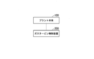
- FIG. 1 is a schematic block diagram illustrating a functional configuration of the gas turbine plant according to the first embodiment.
- the gas turbine plant 1 includes a plant main body 100 and a gas turbine control device 200.
- the gas turbine plant 1 is a gas turbine power generation plant is demonstrated to an example.
- the gas turbine plant 1 is not limited to a gas turbine power plant, but may be a plant including a gas turbine.
- the plant main body 100 operates according to the control of the gas turbine control device 200 to generate a rotational force, and generates power with the generated rotational force.
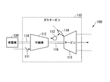
- FIG. 2 is a schematic configuration diagram illustrating a configuration example of the plant main body 100.
- the plant main body 100 includes a gas turbine 110 and a generator 120.
- the gas turbine 110 includes an inlet guide vane 111, a compressor 112, a casing 113, a combustor 114, a turbine 115, and a rotating shaft 116.
- the gas turbine 110 burns fuel gas to generate rotational force.
- the compressor 112 takes in air (atmosphere) and compresses it. Compressed air from the compressor 112 flows into the combustor 114 via the passenger compartment 113.
- An inlet guide vane 111 is provided at the air suction port of the compressor 112.
- the inlet guide vane 111 adjusts the intake air amount to the compressor 112 by adjusting the blade opening degree of the inlet guide vane 111 according to the control of the gas turbine control device 200.
- the combustor 114 mixes the fuel gas supplied from the fuel supply line with the compressed air from the compressor 112 and burns it. Combustion gas generated by the combustion flows into the turbine 115 and hits the blades of the turbine 115 to rotate the turbine 115.
- the turbine 115, the compressor 112, and the generator 120 are connected by a rotating shaft 116.
- the rotating shaft 116 transmits a rotational force from the turbine 115 to the compressor 112, and the compressor 112 compresses air with the rotational force from the turbine 115. Further, the rotating shaft 116 transmits the rotational force from the turbine 115 by the generator 120, and the generator 120 generates power by the rotational force from the turbine 115.
- the gas turbine control device 200 controls the plant main body 100.
- the gas turbine control device 200 obtains a turbine inlet temperature estimated value in real time, and controls the gas turbine 110 based on the obtained estimated value.
- the turbine inlet temperature here is the temperature at the combustion gas inlet of the turbine 115.
- the gas turbine control device 200 is configured by using a computer such as EWS (Engineering WorkStation) or PLC (Programmable Logic Controller).
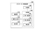
- FIG. 3 is a schematic block diagram showing a functional configuration of the gas turbine control device 200.
- the gas turbine control device 200 includes a communication unit 210, an operation input unit 220, a display unit 230, a storage unit 280, and a control unit 290.
- the control unit 290 includes a first estimation unit 291, a second estimation unit 292, and a correction unit 293.
- the communication unit 210 communicates with other devices.
- the communication unit 210 receives sensor data from each sensor provided in the plant main body 100.
- the communication unit 210 transmits a control signal to each unit of the plant main body 100.
- the operation input unit 220 includes an input device such as an operation panel, a keyboard, or a combination thereof, and receives a user operation.
- the display unit 230 includes a display device such as a display screen such as a display panel or a liquid crystal panel, or a combination thereof, and displays various types of information.
- storage part 280 is comprised using the memory
- the control unit 290 controls each part of the gas turbine control device 200 and executes various functions.
- the control unit 290 is configured by, for example, a CPU (Central Processing Unit) provided in the gas turbine control device 200 reads out and executes a program from the storage unit 280.
- the first estimation unit 291 estimates the first temperature.
- the first temperature here is a turbine inlet temperature estimated value based on the first model.
- the first model here is a physical model using the fuel flow rate to the gas turbine.
- the physical model using the fuel flow rate to the gas turbine is a model that calculates the physical quantity in response to the input of the fuel flow rate to the gas turbine.
- a known model can be used as the first model.
- the data format of the physical model in the gas turbine control device 200 is not limited to a specific format.
- the physical model may be shown in the form of a mathematical expression such as a function or an equation, or may be shown in a table format indicating the correspondence between the input and the output.
- the relationship between the change in the fuel flow rate and the change in the turbine inlet temperature is such that the turbine inlet temperature changes in accordance with the change in the fuel flow rate.
- the first estimation unit 291 estimates the turbine inlet temperature using the fuel flow rate to the gas turbine 110, so that the change in the turbine inlet temperature with respect to the change in the fuel flow rate can be estimated without delay.
- the first temperature estimated by the first estimation unit 291 has good responsiveness at the time of transition in which the state of the gas turbine changes.
- the first estimation unit 291 may use a physical model indicating the heat balance in the combustor as the first model.
- the first estimation unit 291 may use a model represented by Expression (1) described in Japanese Patent Laid-Open No. 2005-240608.
- c P4 represents the combustion gas specific heat [kcal / kg ° C.].
- V cb represents the volume [m 3 ] of the turbine casing to the transition piece of the turbine.
- ⁇ 4 represents the specific gravity of combustion gas [kg / m 3 ].
- T 4 represents a is an estimated target turbine inlet temperature [° C.].
- t indicates time [sec].
- c Pf represents fuel specific heat [kcal / kg ° C.].
- G ′ f represents the fuel flow rate measurement value [kg / s] compensated for delay.
- T ′ f indicates the measured fuel temperature value [° C.] compensated for delay.
- c P3 represents vehicle compartment specific heat [kcal / kg ° C.].
- G ′ 3 represents the combustor inflow air flow rate measurement value [kg / s] compensated for delay. May be the calculated value is used as the G '3.
- T ′ 3 indicates a measured value of the cabin temperature [° C.] compensated for delay.
- ⁇ indicates the thermal efficiency [kcal / kg] of the combustor.
- H f represents the calorific value [kcal / kg].
- G ′ 4 indicates the turbine inlet combustion gas flow rate [kg / s] compensated for delay.
- G ′ 4 G ′ 3 + G ′ f .
- V cb are design values and are calculated at the design stage.
- the second estimation unit 292 estimates the second temperature.
- the second temperature here is a turbine inlet temperature estimated value based on the second model.
- the second model here is a physical model using the exhaust gas temperature of the gas turbine.
- the physical model using the exhaust gas temperature of the gas turbine here is a model that receives the input of the exhaust gas temperature of the gas turbine and calculates a physical quantity.
- a known model can be used as the second model.
- the exhaust gas temperature is a temperature at which combustion gas is discharged from the turbine as exhaust gas via the turbine. Therefore, the turbine inlet temperature and the exhaust gas temperature are the combustion gas temperatures at the turbine inlet and outlet, respectively, and have a strong correlation.
- the second estimation unit 292 can estimate the turbine inlet temperature (second temperature) with high accuracy by estimating the turbine inlet temperature based on the exhaust gas temperature. In particular, when the gas turbine is in a constant state, the second temperature is more accurate than the first temperature.
- the exhaust gas temperature is the temperature of the combustion gas before passing through the turbine
- the exhaust gas temperature is the temperature of the combustion gas after passing through the turbine. Changes late.
- a delay occurs during temperature measurement by the temperature sensor. In particular, when trying to measure the exhaust gas temperature with high accuracy, the measurement delay may be large. For this reason, the first temperature estimated by the first estimation unit 291 has better responsiveness at the time when the state of the gas turbine changes than the second temperature estimated by the second estimation unit 292.
- the second estimation unit 292 may use a model indicating a heat balance using the exhaust gas temperature of the gas turbine as the second model.
- a model indicating a heat balance using the exhaust gas temperature of the gas turbine As the second model.
- an example of the second model used by the second estimation unit 292 will be described with reference to Expressions (2) to (8).
- the work W t of the turbine is expressed as in equation (2).
- Equation (3) The heat drop ⁇ H in the turbine is expressed as in Equation (3).
- H 1T indicates the enthalpy of the turbine inlet.
- H 2T indicates the enthalpy of the turbine outlet.
- Expression (4) is obtained from Expression (2) and Expression (3).
- Equation (4) can be transformed into Equation (5).
- the function f here is a function determined by physical properties.
- the storage unit 280 stores the function f in advance.
- Expression (7) is obtained from Expression (5) and Expression (6).
- the second estimation unit 292 may use the model represented by Expression (7) as the second model. In this case, the second estimation unit 292 calculates the work W t of the turbine from the generator output Pe based on the equation (8).
- W c indicates the work of the compressor
- W LOSS indicates mechanical loss (Mechanical Loss).
- the second estimation unit 292 acquires the value of W c and the value of W LOSS by calculation.
- the second estimating portion 292 may be may also be a measured value is used as the turbine flow rate through G t of the formula (7) so as to use the calculated values.
- the second estimation unit 292 calculates based on the enthalpy H 2T turbine outlet to a known enthalpy calculation method.
- the correcting unit 293 corrects the first temperature based on the second temperature and calculates a turbine inlet temperature estimated value.
- the correction unit 293 may correct the first temperature using a correction coefficient determined based on the ratio between the first temperature and the second temperature. For example, the correction unit 293 may calculate the correction coefficient X based on Expression (9).
- ⁇ is an adjustment coefficient represented by a constant of 0 ⁇ ⁇ 1.
- the value of the adjustment coefficient ⁇ is set according to an input operation performed by the operator using the operation input unit 220, for example.
- T1T t indicates the second temperature.
- T1T f indicates the first temperature.
- X ′ represents the past value of the correction coefficient X.
- the correction coefficient X corresponds to an example of the correction coefficient determined based on the ratio between the first temperature and the second temperature.
- amendment part 293 correct
- T1T e shows a turbine inlet temperature estimate.
- each of the first temperature T1T f and the second temperature T1T t is weighted by multiplying by a coefficient, and these values are summed.
- the turbine inlet temperature is more responsive than the case of only the second temperature T1T t by the term of the first temperature T1T f (“(1- ⁇ ) ⁇ X ′ ⁇ T1T f ”). It obtained an estimate T1T e.
- the second temperature T1T t section ( "alpha ⁇ T1T t") by the first temperature T1T f higher turbine inlet temperature estimate more accurate than when only T1T e Can be obtained.
- the correction unit 293, by correcting the first temperature T1T f, so to reflect the second temperature T1T t in turbine inlet temperature estimate T1T e, there is no need to switch the process between the time of settling and transient. Thereby, the sudden change of the estimated value accompanying process switching can be avoided.
- the load on the control unit 290 can be light in that it is not necessary to determine whether it is stationary or in transition, and it is not necessary to switch processing.
- FIG. 4 is a graph showing a first example of the estimated turbine inlet temperature based on the heat balance model using the generator output.
- FIG. 4 shows an example of the turbine inlet temperature estimated value based on the heat balance model using the generator output when the turbine load increases.
- the horizontal axis in FIG. 4 indicates time.
- the vertical axis represents temperature.
- Line L11 shows an example of the actual value of the turbine inlet temperature.
- Line L12 shows an example of the turbine inlet temperature estimated value based on the heat balance model using the generator output.
- the GT output measured value, the atmospheric temperature measured value, and the IGV opening command value are applied to the heat balance data to estimate the turbine inlet temperature. May be requested.
- the gas turbine control device 200 can estimate the turbine inlet temperature with higher accuracy even during the transient state than in the case of estimating the turbine inlet temperature based on the heat balance model using the generator output.
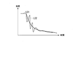
- FIG. 5 is a graph showing a second example of the turbine inlet temperature estimation based on the heat balance model using the generator output.
- FIG. 5 shows an example of the turbine inlet temperature estimated value based on the heat balance model using the generator output at the time of turbine load drop.
- the horizontal axis in FIG. 5 indicates time.
- the vertical axis represents temperature.
- Line L21 shows an example of the actual value of the turbine inlet temperature.
- Line L22 shows an example of the turbine inlet temperature estimated value based on the heat balance model using the generator output.
- the generator output may vibrate due to the relationship with the power system.
- the estimated turbine inlet temperature based on the heat balance model using the generator output vibrates.
- this vibration is due to the relationship between the generator and the power system, and it is considered that the turbine inlet temperature changes without vibration as in the example of FIG.
- the gas turbine is controlled using a turbine inlet temperature estimated value that is significantly different from the actual turbine inlet temperature, a trip due to misfire or a combustor damage due to combustion vibration may occur.
- the gas turbine control device 200 can estimate the turbine inlet temperature with higher accuracy even during the transient state than in the case of estimating the turbine inlet temperature based on the heat balance model using the generator output.
- the correction performed by the correction unit 293 is not limited to that shown in Expression (10) and Expression (11).
- various corrections can be used that ensure the responsiveness at the time of transition based on the first temperature and obtain the accuracy at the time of stabilization based on the second temperature.
- the correction unit 293 may estimate the turbine inlet temperature estimate T1T e based on the equation (12).
- LAG is a function indicating a first-order lag element.
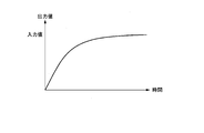
- FIG. 6 is a graph illustrating an example of the value of the function LAG.
- FIG. 6 shows the value of the function LAG when the input value to the function LAG is constant with respect to time.
- the output value of the function LAG approaches the input value as time elapses.
- Expression (12) instead of the function LAG, another function whose output value approaches the input value as time elapses may be used. The same applies to equation (13) described later.
- the correction unit 293 estimates the turbine inlet temperature estimate T1T e using the equation (12), to ensure the responsiveness of the estimation of the turbine inlet temperature, and it is possible to improve the estimation accuracy.
- the correction unit 293 may estimate the turbine inlet temperature estimate T1T e based on equation (13).
- the correction unit 293 estimates the turbine inlet temperature estimate T1T e using equation (13), to ensure the responsiveness of the estimation of the turbine inlet temperature, and it is possible to improve the estimation accuracy.
- the correction unit 293 may estimate the turbine inlet temperature estimate T1T e based on equation (14).
- the value of the function LAG is a value obtained by subtracting the first temperature T1T f from the second temperature T1T t (“T1T t ⁇ T1T f ”), and the estimated turbine inlet temperature T1T e is It becomes equal to the second temperature T1T t .
- T1T t ⁇ T1T f the estimated turbine inlet temperature T1T e is It becomes equal to the second temperature T1T t .
- the correction unit 293 estimates the turbine inlet temperature estimate T1T e using the equation (14), to ensure the responsiveness of the estimation of the turbine inlet temperature, and it is possible to improve the estimation accuracy.
- the correction unit 293 may estimate the turbine inlet temperature estimate T1T e based on equation (15).
- LAG (T1T t / T1T f )” in Expression (15) corresponds to an example of the correction coefficient determined based on the ratio between the first temperature and the second temperature.
- the value of the function LAG is a value obtained by dividing the second temperature T1T t by the first temperature T1T f (“T1T t / T1T f ”), and the estimated turbine inlet temperature T1T e is It becomes equal to the second temperature T1T t .
- T1T t / T1T f the estimated turbine inlet temperature
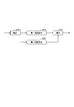
- FIG. 7 is a diagram illustrating an example of a processing procedure for the gas turbine control device 200 to obtain an estimated turbine inlet temperature.
- the gas turbine control device 200 repeats the process of FIG. 7 at predetermined intervals, for example.
- the first estimation unit 291 calculates the first temperature using the first model (step S111).
- the second estimation unit 292 calculates the second temperature using the second model (step S121).
- the first estimation unit 291 and the second estimation unit 292 may execute the process in step S111 and the process in step S121 in parallel or sequentially.
- the correcting unit 293 corrects the first temperature obtained in step S111 based on the second temperature obtained in step S121 (step S131). After step S131, the process of FIG.
- the first estimation unit 291 estimates the first temperature T1T f that is the turbine inlet temperature estimated value based on the first model that is a physical model using the fuel flow rate to the gas turbine 110.
- the second estimation unit 292 estimates a second temperature T1T t that is a turbine inlet temperature estimated value based on a second model that is a physical model using the exhaust gas temperature of the gas turbine 110.
- Correction unit 293 calculates the turbine inlet temperature estimate T1T e the first temperature correction to based on the second temperature.
- in terms of using the first temperature T1T f based on the fuel flow rate can be ensured responsiveness of the turbine inlet temperature estimate T1T e.
- the gas turbine control device 200 in terms of using the second temperature T1T t based on exhaust gas temperature, it is possible to estimate the turbine inlet temperature estimate T1T e with high accuracy. As described above, according to the gas turbine control device 200, it is possible to secure responsiveness and to improve the estimation accuracy for the estimation of the turbine inlet temperature.
- the correction unit 293, by correcting the first temperature T1T f, so to reflect the second temperature T1T t in turbine inlet temperature estimate T1T e, there is no need to switch the process between the time of settling and transient. Thereby, the sudden change of the estimated value accompanying process switching can be avoided.
- the load on the control unit 290 can be light in that it is not necessary to determine whether it is stationary or in transition, and it is not necessary to switch processing.
- the first estimation unit 291 estimates the first temperature based on the first model indicating the heat balance in the combustor 114.
- the second estimation unit 292 estimates the second temperature based on the second model indicating the heat balance using the exhaust gas temperature of the turbine 115.
- the correction unit 293 corrects the first temperature using a correction coefficient determined based on the ratio between the first temperature and the second temperature.
- FIG. 8 is a schematic block diagram illustrating a functional configuration of the gas turbine control device according to the second embodiment.
- the gas turbine control device 300 includes a communication unit 210, an operation input unit 220, a display unit 230, a storage unit 280, and a control unit 390.
- the control unit 390 includes a first estimation unit 291, a second estimation unit 292, a correction unit 293, and an input value correction unit 394. 8 having the same functions corresponding to those in FIG.
- the gas turbine control device 300 is different from the gas turbine control device 200 in that the control device 390 includes an input value correction unit 394. Other than that is the same as that of the gas turbine control apparatus 200. In the configuration of FIG. 1, a gas turbine control device 300 can be used instead of the gas turbine control device 200.
- the input value correction unit 394 performs correction using the estimated value obtained by the calculation using the second model for at least one of the estimated values to be input to the first model.
- values obtained by calculation such as the fuel flow rate and the air flow rate may include an error with respect to the actual values.
- the input value correction unit 394 corrects the value obtained in the calculation process of the second model with respect to the value to be input to the first model, as described for the correction of the turbine inlet temperature. I do. Thereby, in the gas turbine control device 300, the estimation accuracy of the turbine inlet temperature can be further increased.
- FIG. 9 is a diagram illustrating an example of a processing procedure in which the gas turbine control device 300 obtains a turbine inlet temperature estimated value.
- the gas turbine control device 300 repeats the process of FIG. 7 at predetermined intervals, for example.
- the input value correction unit 394 performs correction using the estimated value obtained by the calculation using the second model for at least one of the estimated values that are input to the first model. This is performed (step S211).
- Steps S212, S221, and S231 are the same as steps S111, S121, and S131 of FIG. 7, respectively.
- step S231 the process of FIG.
- the input value correction unit 394 performs correction using the estimated value obtained by the calculation using the second model on at least one of the estimated values that are input to the first model. . Thereby, in the gas turbine control device 300, the estimation accuracy of the turbine inlet temperature can be further increased.
- the computer that performs the process of the first estimation unit 291 and the computer that performs the process of the second estimation unit 292 may be the same computer. It may be a separate computer.
- the calculation of the first temperature using the first model does not require repeated calculation and the processing load is relatively light.
- a program for realizing all or part of the functions of the control unit 290 or 390 is recorded on a computer-readable recording medium, and the program recorded on the recording medium is read into a computer system and executed. You may process each part.
- the “computer system” includes an OS and hardware such as peripheral devices. Further, the “computer system” includes a homepage providing environment (or display environment) if a WWW system is used.
- the “computer-readable recording medium” refers to a storage device such as a flexible medium, a magneto-optical disk, a portable medium such as a ROM or a CD-ROM, and a hard disk incorporated in a computer system.
- the program may be a program for realizing a part of the functions described above, and may be a program capable of realizing the functions described above in combination with a program already recorded in a computer system.
- An embodiment of the present invention includes a first estimation unit that estimates a first temperature that is a turbine inlet temperature estimation value based on a first model that is a physical model using a fuel flow rate to a gas turbine, and an exhaust gas temperature of the gas turbine.
- a second estimation unit that estimates a second temperature that is a turbine inlet temperature estimation value based on a second model that is a physical model using a turbine, and a turbine inlet temperature estimation by correcting the first temperature based on the second temperature
- a correction unit that calculates a value.
- the responsiveness can be secured for the estimation of the turbine inlet temperature, and the estimation accuracy can be increased.
Landscapes
- Engineering & Computer Science (AREA)
- Chemical & Material Sciences (AREA)
- Combustion & Propulsion (AREA)
- Mechanical Engineering (AREA)
- General Engineering & Computer Science (AREA)
- Control Of Turbines (AREA)
- Feedback Control In General (AREA)
- Engine Equipment That Uses Special Cycles (AREA)
Priority Applications (4)
| Application Number | Priority Date | Filing Date | Title |
|---|---|---|---|
| US16/484,254 US11248537B2 (en) | 2017-02-23 | 2018-02-22 | Gas turbine control device, gas turbine plant, and gas turbine control method |
| DE112018000962.9T DE112018000962B4 (de) | 2017-02-23 | 2018-02-22 | Gasturbinensteuervorrichtung, gasturbinenanlage und gasturbinensteuerverfahren |
| CN201880010739.7A CN110268148B (zh) | 2017-02-23 | 2018-02-22 | 燃气轮机控制装置、燃气轮机成套设备以及燃气轮机控制方法 |
| KR1020197023253A KR102290578B1 (ko) | 2017-02-23 | 2018-02-22 | 가스 터빈 제어 장치, 가스 터빈 플랜트 및 가스 터빈 제어 방법 |
Applications Claiming Priority (2)
| Application Number | Priority Date | Filing Date | Title |
|---|---|---|---|
| JP2017032682A JP6875146B2 (ja) | 2017-02-23 | 2017-02-23 | ガスタービン制御装置、ガスタービンプラントおよびガスタービン制御方法 |
| JP2017-032682 | 2017-02-23 |
Publications (1)
| Publication Number | Publication Date |
|---|---|
| WO2018155552A1 true WO2018155552A1 (ja) | 2018-08-30 |
Family
ID=63253402
Family Applications (1)
| Application Number | Title | Priority Date | Filing Date |
|---|---|---|---|
| PCT/JP2018/006436 WO2018155552A1 (ja) | 2017-02-23 | 2018-02-22 | ガスタービン制御装置、ガスタービンプラントおよびガスタービン制御方法 |
Country Status (6)
Families Citing this family (7)
| Publication number | Priority date | Publication date | Assignee | Title |
|---|---|---|---|---|
| JP6763629B2 (ja) * | 2016-12-15 | 2020-09-30 | 三菱パワー株式会社 | ガスタービン制御装置、ガスタービン制御方法 |
| CN110889217B (zh) * | 2019-11-20 | 2023-06-27 | 中国人民解放军海军工程大学 | 燃气轮机燃烧室一维仿真模型出口温度的修正方法 |
| US11525409B2 (en) | 2020-09-28 | 2022-12-13 | General Electric Company | Temperature based gas turbine control and method |
| CN113374582B (zh) * | 2021-07-28 | 2022-09-27 | 哈电发电设备国家工程研究中心有限公司 | 一种燃气轮机运行状态评估装置及方法 |
| JP2023166083A (ja) * | 2022-05-09 | 2023-11-21 | 三菱重工業株式会社 | ガスタービン制御装置、ガスタービン制御方法、及びプログラム |
| JP7216245B1 (ja) | 2022-08-31 | 2023-01-31 | 三菱重工業株式会社 | ガスタービンの性能評価方法、この方法をコンピュータに実行させるプログラム、及びこの方法を実行する装置 |
| US20240094067A1 (en) * | 2022-09-19 | 2024-03-21 | Pratt & Whitney Canada Corp. | Systems and methods for determining gas turbine engine temperatures |
Citations (2)
| Publication number | Priority date | Publication date | Assignee | Title |
|---|---|---|---|---|
| JP2012002126A (ja) * | 2010-06-16 | 2012-01-05 | Mitsubishi Heavy Ind Ltd | 排ガス温度推定装置、排ガス温度推定方法、及びガスタービンプラント |
| JP2016023604A (ja) * | 2014-07-22 | 2016-02-08 | 三菱重工業株式会社 | 温度推定装置、燃焼器、ガスタービン、温度推定方法及びプログラム |
Family Cites Families (16)
| Publication number | Priority date | Publication date | Assignee | Title |
|---|---|---|---|---|
| US4258545A (en) * | 1978-06-15 | 1981-03-31 | General Electric Company | Optimal control for a gas turbine engine |
| US5081830A (en) * | 1990-05-25 | 1992-01-21 | United Technologies Corporation | Method of restoring exhaust gas temperature margin in a gas turbine engine |
| JP2001329855A (ja) | 2000-05-19 | 2001-11-30 | Ishikawajima Harima Heavy Ind Co Ltd | ガスタービンのタービン入口温度予測方法 |
| US6715916B2 (en) * | 2001-02-08 | 2004-04-06 | General Electric Company | System and method for determining gas turbine firing and combustion reference temperatures having correction for water content in fuel |
| US6931857B2 (en) * | 2003-05-30 | 2005-08-23 | United Technologies Corporation | Rotor inlet temperature control for turbo machine |
| JP2005240608A (ja) | 2004-02-25 | 2005-09-08 | Mitsubishi Heavy Ind Ltd | ガスタービン制御装置 |
| JP4745767B2 (ja) * | 2005-09-08 | 2011-08-10 | 三菱重工業株式会社 | 燃料流量制御装置及び発電システム並びに燃料流量制御方法 |
| JP4831820B2 (ja) * | 2006-05-22 | 2011-12-07 | 三菱重工業株式会社 | ガスタービン出力学習回路及びこれを備えたガスタービンの燃焼制御装置 |
| US8126629B2 (en) | 2008-04-25 | 2012-02-28 | General Electric Company | Method and system for operating gas turbine engine systems |
| EP2177963A1 (en) | 2008-10-17 | 2010-04-21 | ALSTOM Technology Ltd | Gas turbine model and method for the modeling of a gas turbine |
| US8516829B2 (en) * | 2009-05-27 | 2013-08-27 | General Electric Company | Systems and methods for modifying the performance of a gas turbine |
| US8276363B2 (en) * | 2010-08-10 | 2012-10-02 | General Electric Company | Method for compensating for combustion efficiency in fuel control system |
| JP6217451B2 (ja) | 2014-02-26 | 2017-10-25 | 三菱日立パワーシステムズ株式会社 | 燃料制御装置、燃焼器、ガスタービン、制御方法及びプログラム |
| JP6335720B2 (ja) | 2014-08-26 | 2018-05-30 | 三菱日立パワーシステムズ株式会社 | 制御装置、システム及び制御方法 |
| JP2017032682A (ja) | 2015-07-30 | 2017-02-09 | キヤノン株式会社 | トナー |
| JP6706936B2 (ja) | 2016-03-09 | 2020-06-10 | 三菱日立パワーシステムズ株式会社 | ガスタービンの制御装置及びガスタービンの制御方法 |
-
2017
- 2017-02-23 JP JP2017032682A patent/JP6875146B2/ja active Active
-
2018
- 2018-02-22 KR KR1020197023253A patent/KR102290578B1/ko active Active
- 2018-02-22 CN CN201880010739.7A patent/CN110268148B/zh active Active
- 2018-02-22 DE DE112018000962.9T patent/DE112018000962B4/de active Active
- 2018-02-22 US US16/484,254 patent/US11248537B2/en active Active
- 2018-02-22 WO PCT/JP2018/006436 patent/WO2018155552A1/ja active IP Right Grant
Patent Citations (2)
| Publication number | Priority date | Publication date | Assignee | Title |
|---|---|---|---|---|
| JP2012002126A (ja) * | 2010-06-16 | 2012-01-05 | Mitsubishi Heavy Ind Ltd | 排ガス温度推定装置、排ガス温度推定方法、及びガスタービンプラント |
| JP2016023604A (ja) * | 2014-07-22 | 2016-02-08 | 三菱重工業株式会社 | 温度推定装置、燃焼器、ガスタービン、温度推定方法及びプログラム |
Also Published As
| Publication number | Publication date |
|---|---|
| KR20190102268A (ko) | 2019-09-03 |
| US20190383222A1 (en) | 2019-12-19 |
| US11248537B2 (en) | 2022-02-15 |
| JP6875146B2 (ja) | 2021-05-19 |
| KR102290578B1 (ko) | 2021-08-17 |
| CN110268148B (zh) | 2022-03-04 |
| JP2018135859A (ja) | 2018-08-30 |
| DE112018000962T5 (de) | 2019-12-12 |
| CN110268148A (zh) | 2019-09-20 |
| DE112018000962B4 (de) | 2025-06-12 |
Similar Documents
| Publication | Publication Date | Title |
|---|---|---|
| WO2018155552A1 (ja) | ガスタービン制御装置、ガスタービンプラントおよびガスタービン制御方法 | |
| JP6453302B2 (ja) | 小型空気熱モデルベースの制御システム | |
| JP6427841B2 (ja) | 燃料制御装置、燃焼器、ガスタービン、制御方法及びプログラム | |
| CN105849389B (zh) | 燃料控制装置、燃烧器、燃气涡轮、以及控制方法 | |
| JP2010276023A (ja) | ガスタービンの性能を補正するシステム及び方法 | |
| Chesse et al. | Impact of the heat transfer on the performance calculations of automotive turbocharger compressor | |
| JP2010255627A (ja) | タービン部品にサージ保護を与えるためのシステム及び方法 | |
| US20140005909A1 (en) | Real time linearization of a component-level gas turbine engine model for model-based control | |
| CN110199102A (zh) | 燃气涡轮发动机燃料控制系统和方法 | |
| Pinelli et al. | Aeromechanical characterization of a last stage steam blade at low load operation: Part 2—computational modelling and comparison | |
| JP5535883B2 (ja) | 制御装置および状態量取得装置 | |
| EP3396136B1 (en) | Gas turbine system and control apparatus and method thereof | |
| JP5845705B2 (ja) | ガスタービン性能推定装置 | |
| JP2003293795A (ja) | ガスタービン制御装置及びガスタービン制御方法 | |
| JP2005240608A (ja) | ガスタービン制御装置 | |
| JP5968248B2 (ja) | 燃料ガスカロリー推定装置、燃料ガスカロリー推定方法およびプログラム | |
| Sanghi et al. | Aerothermal model for real-time digital simulation of a mixed-flow turbofan engine | |
| JP5615052B2 (ja) | ガスタービンプラント及びガスタービンプラントの制御方法 | |
| JP6483571B2 (ja) | 性能推定装置及び性能推定方法 | |
| JP5523950B2 (ja) | 燃料カロリー演算装置および燃料カロリー演算方法 | |
| Kaufmann | Using turbocharger maps in gas exchange simulation and engine control units | |
| JP2014194175A (ja) | 遅れ時間の算出方法、原動機の出力算出方法、状態量の制御方法、これらの方法を実行する装置 | |
| JP2024111769A (ja) | 制御装置 | |
| JP2012149551A (ja) | ガスタービン制御装置およびガスタービン制御方法 | |
| JP2013131061A (ja) | 内燃機関の制御パラメータ調整装置及びその調整方法 |
Legal Events
| Date | Code | Title | Description |
|---|---|---|---|
| 121 | Ep: the epo has been informed by wipo that ep was designated in this application |
Ref document number: 18757933 Country of ref document: EP Kind code of ref document: A1 |
|
| ENP | Entry into the national phase |
Ref document number: 20197023253 Country of ref document: KR Kind code of ref document: A |
|
| 122 | Ep: pct application non-entry in european phase |
Ref document number: 18757933 Country of ref document: EP Kind code of ref document: A1 |
|
| WWG | Wipo information: grant in national office |
Ref document number: 112018000962 Country of ref document: DE |