WO2018155015A1 - 燃料ガス加熱器及び燃料ガス加熱器の支持構造物並びに燃料ガス加熱器の洗浄方法 - Google Patents
燃料ガス加熱器及び燃料ガス加熱器の支持構造物並びに燃料ガス加熱器の洗浄方法 Download PDFInfo
- Publication number
- WO2018155015A1 WO2018155015A1 PCT/JP2018/001265 JP2018001265W WO2018155015A1 WO 2018155015 A1 WO2018155015 A1 WO 2018155015A1 JP 2018001265 W JP2018001265 W JP 2018001265W WO 2018155015 A1 WO2018155015 A1 WO 2018155015A1
- Authority
- WO
- WIPO (PCT)
- Prior art keywords
- gas
- container
- fuel gas
- opening
- heat transfer
- Prior art date
- Legal status (The legal status is an assumption and is not a legal conclusion. Google has not performed a legal analysis and makes no representation as to the accuracy of the status listed.)
- Ceased
Links
Images


Classifications
-
- F—MECHANICAL ENGINEERING; LIGHTING; HEATING; WEAPONS; BLASTING
- F02—COMBUSTION ENGINES; HOT-GAS OR COMBUSTION-PRODUCT ENGINE PLANTS
- F02C—GAS-TURBINE PLANTS; AIR INTAKES FOR JET-PROPULSION PLANTS; CONTROLLING FUEL SUPPLY IN AIR-BREATHING JET-PROPULSION PLANTS
- F02C7/00—Features, components parts, details or accessories, not provided for in, or of interest apart form groups F02C1/00 - F02C6/00; Air intakes for jet-propulsion plants
- F02C7/22—Fuel supply systems
- F02C7/224—Heating fuel before feeding to the burner
-
- F—MECHANICAL ENGINEERING; LIGHTING; HEATING; WEAPONS; BLASTING
- F01—MACHINES OR ENGINES IN GENERAL; ENGINE PLANTS IN GENERAL; STEAM ENGINES
- F01D—NON-POSITIVE DISPLACEMENT MACHINES OR ENGINES, e.g. STEAM TURBINES
- F01D25/00—Component parts, details, or accessories, not provided for in, or of interest apart from, other groups
- F01D25/002—Cleaning of turbomachines
-
- F—MECHANICAL ENGINEERING; LIGHTING; HEATING; WEAPONS; BLASTING
- F02—COMBUSTION ENGINES; HOT-GAS OR COMBUSTION-PRODUCT ENGINE PLANTS
- F02C—GAS-TURBINE PLANTS; AIR INTAKES FOR JET-PROPULSION PLANTS; CONTROLLING FUEL SUPPLY IN AIR-BREATHING JET-PROPULSION PLANTS
- F02C7/00—Features, components parts, details or accessories, not provided for in, or of interest apart form groups F02C1/00 - F02C6/00; Air intakes for jet-propulsion plants
- F02C7/22—Fuel supply systems
- F02C7/222—Fuel flow conduits, e.g. manifolds
-
- F—MECHANICAL ENGINEERING; LIGHTING; HEATING; WEAPONS; BLASTING
- F02—COMBUSTION ENGINES; HOT-GAS OR COMBUSTION-PRODUCT ENGINE PLANTS
- F02C—GAS-TURBINE PLANTS; AIR INTAKES FOR JET-PROPULSION PLANTS; CONTROLLING FUEL SUPPLY IN AIR-BREATHING JET-PROPULSION PLANTS
- F02C7/00—Features, components parts, details or accessories, not provided for in, or of interest apart form groups F02C1/00 - F02C6/00; Air intakes for jet-propulsion plants
- F02C7/32—Arrangement, mounting, or driving, of auxiliaries
-
- F—MECHANICAL ENGINEERING; LIGHTING; HEATING; WEAPONS; BLASTING
- F28—HEAT EXCHANGE IN GENERAL
- F28D—HEAT-EXCHANGE APPARATUS, NOT PROVIDED FOR IN ANOTHER SUBCLASS, IN WHICH THE HEAT-EXCHANGE MEDIA DO NOT COME INTO DIRECT CONTACT
- F28D7/00—Heat-exchange apparatus having stationary tubular conduit assemblies for both heat-exchange media, the media being in contact with different sides of a conduit wall
- F28D7/06—Heat-exchange apparatus having stationary tubular conduit assemblies for both heat-exchange media, the media being in contact with different sides of a conduit wall the conduits having a single U-bend
-
- F—MECHANICAL ENGINEERING; LIGHTING; HEATING; WEAPONS; BLASTING
- F28—HEAT EXCHANGE IN GENERAL
- F28G—CLEANING OF INTERNAL OR EXTERNAL SURFACES OF HEAT-EXCHANGE OR HEAT-TRANSFER CONDUITS, e.g. WATER TUBES OR BOILERS
- F28G1/00—Non-rotary, e.g. reciprocated, appliances
- F28G1/16—Non-rotary, e.g. reciprocated, appliances using jets of fluid for removing debris
- F28G1/163—Non-rotary, e.g. reciprocated, appliances using jets of fluid for removing debris from internal surfaces of heat exchange conduits
-
- F—MECHANICAL ENGINEERING; LIGHTING; HEATING; WEAPONS; BLASTING
- F28—HEAT EXCHANGE IN GENERAL
- F28G—CLEANING OF INTERNAL OR EXTERNAL SURFACES OF HEAT-EXCHANGE OR HEAT-TRANSFER CONDUITS, e.g. WATER TUBES OR BOILERS
- F28G15/00—Details
-
- F—MECHANICAL ENGINEERING; LIGHTING; HEATING; WEAPONS; BLASTING
- F02—COMBUSTION ENGINES; HOT-GAS OR COMBUSTION-PRODUCT ENGINE PLANTS
- F02C—GAS-TURBINE PLANTS; AIR INTAKES FOR JET-PROPULSION PLANTS; CONTROLLING FUEL SUPPLY IN AIR-BREATHING JET-PROPULSION PLANTS
- F02C3/00—Gas-turbine plants characterised by the use of combustion products as the working fluid
- F02C3/20—Gas-turbine plants characterised by the use of combustion products as the working fluid using a special fuel, oxidant, or dilution fluid to generate the combustion products
- F02C3/22—Gas-turbine plants characterised by the use of combustion products as the working fluid using a special fuel, oxidant, or dilution fluid to generate the combustion products the fuel or oxidant being gaseous at standard temperature and pressure
-
- F—MECHANICAL ENGINEERING; LIGHTING; HEATING; WEAPONS; BLASTING
- F05—INDEXING SCHEMES RELATING TO ENGINES OR PUMPS IN VARIOUS SUBCLASSES OF CLASSES F01-F04
- F05D—INDEXING SCHEME FOR ASPECTS RELATING TO NON-POSITIVE-DISPLACEMENT MACHINES OR ENGINES, GAS-TURBINES OR JET-PROPULSION PLANTS
- F05D2230/00—Manufacture
- F05D2230/72—Maintenance
-
- F—MECHANICAL ENGINEERING; LIGHTING; HEATING; WEAPONS; BLASTING
- F05—INDEXING SCHEMES RELATING TO ENGINES OR PUMPS IN VARIOUS SUBCLASSES OF CLASSES F01-F04
- F05D—INDEXING SCHEME FOR ASPECTS RELATING TO NON-POSITIVE-DISPLACEMENT MACHINES OR ENGINES, GAS-TURBINES OR JET-PROPULSION PLANTS
- F05D2250/00—Geometry
- F05D2250/50—Inlet or outlet
- F05D2250/51—Inlet
-
- F—MECHANICAL ENGINEERING; LIGHTING; HEATING; WEAPONS; BLASTING
- F05—INDEXING SCHEMES RELATING TO ENGINES OR PUMPS IN VARIOUS SUBCLASSES OF CLASSES F01-F04
- F05D—INDEXING SCHEME FOR ASPECTS RELATING TO NON-POSITIVE-DISPLACEMENT MACHINES OR ENGINES, GAS-TURBINES OR JET-PROPULSION PLANTS
- F05D2250/00—Geometry
- F05D2250/50—Inlet or outlet
- F05D2250/52—Outlet
-
- F—MECHANICAL ENGINEERING; LIGHTING; HEATING; WEAPONS; BLASTING
- F05—INDEXING SCHEMES RELATING TO ENGINES OR PUMPS IN VARIOUS SUBCLASSES OF CLASSES F01-F04
- F05D—INDEXING SCHEME FOR ASPECTS RELATING TO NON-POSITIVE-DISPLACEMENT MACHINES OR ENGINES, GAS-TURBINES OR JET-PROPULSION PLANTS
- F05D2250/00—Geometry
- F05D2250/70—Shape
- F05D2250/75—Shape given by its similarity to a letter, e.g. T-shaped
-
- F—MECHANICAL ENGINEERING; LIGHTING; HEATING; WEAPONS; BLASTING
- F28—HEAT EXCHANGE IN GENERAL
- F28F—DETAILS OF HEAT-EXCHANGE AND HEAT-TRANSFER APPARATUS, OF GENERAL APPLICATION
- F28F9/00—Casings; Header boxes; Auxiliary supports for elements; Auxiliary members within casings
- F28F9/22—Arrangements for directing heat-exchange media into successive compartments, e.g. arrangements of guide plates
- F28F2009/222—Particular guide plates, baffles or deflectors, e.g. having particular orientation relative to an elongated casing or conduit
- F28F2009/226—Transversal partitions
-
- F—MECHANICAL ENGINEERING; LIGHTING; HEATING; WEAPONS; BLASTING
- F28—HEAT EXCHANGE IN GENERAL
- F28G—CLEANING OF INTERNAL OR EXTERNAL SURFACES OF HEAT-EXCHANGE OR HEAT-TRANSFER CONDUITS, e.g. WATER TUBES OR BOILERS
- F28G15/00—Details
- F28G2015/006—Arrangements for processing a cleaning fluid after use, e.g. filtering and recycling
Definitions
- the present invention relates to, for example, a fuel gas heater for heating fuel used in a gas turbine, a support structure for the fuel gas heater, and a method for cleaning the fuel gas heater.
- General gas turbine is composed of a compressor, a combustor, and a turbine.
- the compressor compresses the air taken in from the air intake port into high-temperature and high-pressure compressed air.
- the combustor obtains high-temperature and high-pressure combustion gas by supplying fuel gas to the compressed air and burning it.
- the turbine is driven by this combustion gas, and drives a generator connected on the same axis.
- the fuel gas supplied to the combustor of the gas turbine is heated to a predetermined supply temperature using a fuel gas heater.
- the fuel gas heater is composed of a container to which a fuel gas heating medium is supplied and a plurality of heat transfer tubes arranged in the container and through which the fuel gas flows. Therefore, when the fuel gas flows through each heat transfer tube, the fuel gas is heated by exchanging heat with the heating medium supplied into the container.
- This invention solves the subject mentioned above, and aims at providing the fuel gas heater which aims at reduction of a maintenance cost.
- a fuel gas heater of the present invention has a hollow container that is long in the horizontal direction, and has a gas inlet for fuel gas that is partitioned at one end in the longitudinal direction of the container.
- a gas inflow chamber maintenance opening provided opposite to the communication position of the heat transfer tube in the gas inflow chamber, a gas inflow chamber opening / closing lid capable of opening and closing the gas inflow chamber maintenance opening, and the gas outflow chamber
- a gas outflow chamber maintenance opening provided opposite to the communication position of the heat transfer tube, and a gas outflow chamber opening / closing lid capable of opening and closing the gas in
- a gas inflow chamber maintenance opening is provided facing the heat transfer tube communication position in the gas inflow chamber
- a gas outflow chamber maintenance opening is provided facing the heat transfer tube communication position in the gas outflow chamber.
- the part can be opened and closed by each opening / closing lid. Therefore, when each open / close lid is removed from the container, one end of the heat transfer tube can be visually recognized from the outside.For example, by inserting a cleaning nozzle into one end of the heat transfer tube and injecting a cleaning body, The foreign matter adhering to the inner wall surface of the heat transfer tube can be scraped off by the cleaning body moving inside. As a result, the heat transfer tube can be easily maintained in a short time, and the maintenance cost can be reduced.
- the container is partitioned into a first space portion and a second space portion by a partition wall extending in a vertical direction, and adjacent to the partition wall on the upper side of the first space portion.
- a gas inflow chamber is disposed; the gas outflow chamber is disposed below the first space and the end of the container; the plurality of heat transfer tubes are disposed in the second space; An end portion of the heat tube is provided so as to penetrate the partition wall.
- the gas inflow chamber above the first space and arranging the gas outflow chamber below the first space and at the end of the container, the gas inlet and the gas outlet of the fuel gas are the same.
- the manufacturing cost can be reduced.
- the fuel gas heater according to the present invention is characterized in that the gas inlet and the gas outlet are arranged at the upper part of the container side by side in the longitudinal direction of the container.
- the gas inlet and the gas outlet at the upper part of the container, it is possible to easily connect the piping to the gas inlet and the gas outlet even if there are supporting structures for supporting the container on both sides of the container.
- the structure can be simplified.
- the first space portion is partitioned by a partition wall including a vertical wall along the vertical direction and a horizontal wall along the horizontal direction, so that the gas inflow chamber and the gas outflow chamber are provided.
- the gas outflow chamber maintenance opening is provided at one end of the container in the longitudinal direction, and the gas inflow chamber maintenance opening is provided in the vertical wall.
- the gas outflow chamber maintenance opening and the gas inflow chamber maintenance opening can be easily positioned at positions facing the communication position of the heat transfer tube. Can be provided.
- one end of each of the plurality of heat transfer tubes is exposed to the outside of the container through the gas inflow chamber maintenance opening and the gas outflow chamber maintenance opening, and the other end is the gas outflow. It is characterized by being exposed to the outside of the container through a chamber maintenance opening.
- the container is provided with a leaky heating medium discharge port for discharging the heating medium leaked into the gas outflow chamber at the lower part.
- the leaked heating medium can be easily discharged to the outside by providing the leaking heating medium discharge port at the lower part of the container.
- the fuel gas heater of the present invention is characterized in that a leaky heating medium detector is connected to the leaky heating medium discharge port.
- the leakage heating medium detection device to the leakage heating medium discharge port, it is possible to detect the leakage of the heating medium from the leakage heating medium discharge port, and it is possible to easily detect the breakage of the heat transfer tube.
- the support structure of the fuel gas heater includes a support surface supported by a plurality of support pillars on the floor surface, the fuel gas heaters installed on the floor surface and the support table, respectively, and the gas inflow chamber Alternatively, the support column is disposed on the side of the gas outflow chamber.
- the fuel gas heater 10 includes a container 11, a gas inflow chamber 12, a gas outflow chamber 13, a plurality of heat transfer tubes 14, and a water supply supply port (heating).
- Medium supply port) 15, feed water discharge port (heating medium discharge port) 16, gas inflow chamber maintenance opening 17, gas inflow chamber opening / closing lid 18, gas outflow chamber maintenance opening 19, and gas outflow chamber
- An opening / closing lid 20 is provided.
- the water supply / discharge section 23 is disposed at the other end portion in the longitudinal direction of the container 11, and a plurality of U-shaped heat transfer tubes 14 are accommodated therein.
- the plurality of heat transfer tubes 14 are supported by fitting one end portion 14a and the other end portion 14b into a support hole formed in the partition wall 24, and the upper end portion 14a communicates with the gas inflow chamber 12.
- the other end 14 b on the lower side communicates with the gas outflow chamber 13.
- the water supply / discharge portion 23 is provided with a water supply port 15 for supplying boiler water W1 to the second space portion S2 in the lower portion on the partition wall 24 side in the longitudinal direction, and in the second space portion S2 in the upper portion.
- a feed water discharge port 16 for discharging the boiler feed water W2 is provided.
- the feed water supply port 15 and the feed water discharge port 16 are disposed at substantially the same position in the horizontal direction and face each other in the vertical direction.
- a plurality of baffle plates 30 and 31 are fixed to the partition plate 28 and the frame body 29 at a predetermined interval in the longitudinal direction of each heat transfer tube 14.
- the plurality of heat transfer tubes 14 accommodated in the water supply / discharge section 23 are supported by the plurality of baffle plates 30 and 31.
- the plurality of baffle plates 30 and 31 are arranged in the second space portion S2 along the vertical direction and at predetermined intervals in the horizontal direction.
- the baffle plates 30 and 31 are alternately disposed in the horizontal direction and are displaced in the vertical direction.
- the opening area of the gas outflow chamber maintenance opening 19 is set to be larger than the area of the region where the one end portion 14a of each heat transfer tube 14 in the gas inflow chamber 12 communicates. Furthermore, the gas inflow chamber maintenance opening 17 faces a part of the gas outflow chamber maintenance opening 19.
- each of the heat transfer tubes 14 has one end portion 14 a passing through the gas inflow chamber maintenance opening 17 and the gas outflow chamber maintenance opening 19.
- the other end portions 14 b are exposed to the outside of the container 11 through the gas outflow chamber maintenance opening 19.
- the container 11 is provided with a leak water outlet (leakage heat medium discharge port) 41 for discharging the feed water leaked to the gas outflow chamber 13 at the lower part of the gas supply / discharge unit 22 and a communication port 42 on one side. .
- the leak water outlet 41 and the communication port 42 communicate with each other via a communication pipe 43.
- a leak water detection device 44 is connected to the communication pipe 43.
- the leak water detection device 44 includes a test tube 45 that communicates the lowermost portion and the uppermost portion of the communication tube 43, and a measuring instrument 46 that measures the water level of the leak water in the test tube 45.
- the boiler feed water W ⁇ b> 1 moving in the second space S ⁇ b> 2 is higher in temperature and pressure than the fuel gas G ⁇ b> 1 flowing in the heat transfer tube 14. Therefore, for example, when a part of the heat transfer tube 14 is broken, the boiler water supply W1 in the second space S2 enters the inside from the breakage of the heat transfer tube 14, and flows into the gas supply / discharge portion 22 through the heat transfer tube 14. Then, the boiler feed water W ⁇ b> 1 that has flowed into the gas supply / discharge unit 22 flows from the leak water outlet 41 to the communication pipe 43 and then flows to the inspection pipe 45 connected to the communication pipe 43. At this time, the measuring device 46 measures the water level of the leaked water in the test tube 45, whereby the leak (leakage) of the boiler feed water W1 from the heat transfer tube 14 can be detected.
- FIG. 6 is a side view showing the arrangement state of the fuel gas heater of this embodiment
- FIG. 7 is a front view showing the arrangement state of the fuel gas heater.
- two installation bases 102 and 103 are provided on the floor surface 101 at a predetermined interval, and two support columns 104 and 105 are erected on the installation bases 102 and 103, respectively.
- the support base 106 is supported by the support columns 104 and 105 in a horizontal state.
- the fuel gas heater 10 is disposed on each of the installation bases 102 and 103 and supported by the leg 21, and is disposed on the support base 106 and supported by the leg 21.
- the gas connection pipe 112 is connected to the gas outlet 27 of the upper fuel gas heater 10 after the upper end portion is bent in the horizontal direction and the vertical method, and after the lower end portion is bent in the horizontal direction and the vertical method. It is connected to the gas inlet 26 of the lower fuel gas heater 10.
- the support column 104, the gas inlet 26, and the gas outlet 27 are positioned in the longitudinal direction of the fuel gas heater 10. Is almost the same. Therefore, the gas inlet 26 and the gas outlet 27 are provided in the upper part of the fuel gas heater 10, and the gas connection pipe 112 is disposed so as not to interfere with the support pillar 104 and the support base 106.
- FIG. 5 is a schematic diagram illustrating a method for cleaning the fuel gas heater.
- the cleaning device for a fuel gas heater includes a compressor 51, a drain 52, a sand box 53, a cleaning nozzle 54, a recovery box 55, a collision plate 56, and a dust collector 57.
- the fuel gas heater cleaning method of the present embodiment includes a step of removing the gas inflow chamber opening / closing lid 18 and the gas outflow chamber opening / closing lid 20, and the cleaning nozzle 54 with the gas outflow chamber maintenance opening 19 and the gas inflow chamber maintenance opening.
- the fuel gas heater cleaning method of the present embodiment includes a step of causing the abrasive discharged from the other end 14 b of the heat transfer tube 14 to collide with the collision plate 56 and recovering it in the recovery box 55. .
- a cleaning nozzle 54 is connected to the compressor 51 via a drain 52 and a sandbox 53.
- the collision plate 56 is installed along the vertical direction so as to close the lower side of the gas outflow chamber maintenance opening 19 of the gas supply / exhaust unit 22, and the collection box 55 is placed below the collision plate 56, The dust collector 57 is connected.
- the drain 52 is a reservoir for compressed air
- the sandbox 53 is a reservoir for a cut wire as an abrasive.
- the inner wall surface of the heat transfer tube 14 may be damaged when the corner portion collides with the foreign matter fixed to the inner wall surface of the heat transfer tube 14. And can easily scrape off the adhered foreign matter.
- the polishing material injected from the one end portion 14a of the heat transfer tube 14 turns by moving in the U-shaped heat transfer tube 14, and removes foreign matters fixed on the inner wall surface of the heat transfer tube 14. It can be scraped off efficiently. Thereafter, the abrasive and the foreign matter discharged from the other end 14 b of the heat transfer tube 14 descend after colliding with the collision plate 56 and are collected in the collection box 55. Then, the polishing material collected in the collection box 55 is reused after the foreign matter is removed by the dust collector 57.
- the hollow container 11 the gas inflow chamber 12 having a fuel gas inlet 26 that is partitioned at one end of the container 11
- a gas outflow chamber 13 that is partitioned at one end and has a gas outlet 27 for fuel gas, and is accommodated in the container 11, one end 14 a communicates with the gas inflow chamber 12, and the other end 14 b communicates with the gas outflow chamber 13.
- the interior of the container 11 is partitioned into a first space S1 and a second space S2 by a partition wall 24, and a gas is adjacent to the partition wall 24 above the first space portion S1.
- the inflow chamber 12 is disposed, the gas outflow chamber 13 is disposed on the lower side of the first space S1 and the end of the container 11, the plurality of heat transfer tubes 14 are disposed in the second space S2, and the plurality of heat transfer tubes 14 end portions 14 a and 14 b are provided through the partition wall 24.
- the gas inflow chamber 12 and the gas outflow chamber 13 on the upper side of the first space S1
- the gas inlet 26 and the gas outlet 27 for the fuel gas can be provided on the same side, thereby reducing the manufacturing cost. be able to.
- the main stream line of the fuel gas along the vertical direction, it is not necessary to separately provide a drain nozzle (water drain line), a vent nozzle (gas vent) or the like in the main stream line, and the configuration can be simplified. .
- the gas inlet 26 and the gas outlet 27 are arranged in the upper part of the container 11 in the longitudinal direction.
- support structures such as columns and beams are arranged on each side of the fuel gas heater 10 on the lower side, and the structure of the fuel gas heater 10 is arranged. It becomes difficult to provide. Therefore, by arranging the gas inlet 26 and the gas outlet 27 in the upper part of the container 11, piping connected to the gas inlet 26 and the gas outlet 27 can be arranged avoiding the support columns 104 and 105. It can be easily arranged, and the structure can be simplified.
- a leak water detection device 44 is connected to the leak water outlet 41. Therefore, the breakage of the heat transfer tube 14 can be easily detected by detecting the leakage of the boiler feed water W2 from the leak water outlet 41. Further, since the gas outlet 27 is arranged at the upper part of the container 11, the boiler feed water W2 leaking into the gas outflow chamber 13 is prevented from being discharged from the gas outlet 27 and flowing into the fuel supply pipe of the combustor. be able to.
- the support base 106 is supported by the plurality of support pillars 104 and 105 on the installation bases 102 and 103 of the floor surface 101, and the top of the installation bases 102 and 103 and the support base 106.
- the fuel gas heaters 10 are respectively installed on the upper side, and support pillars 104 are arranged on the sides of the gas inflow chamber 12 and the gas outflow chamber 13.
- the step of removing the gas inflow chamber opening / closing lid 18 and the gas outflow chamber opening / closing lid 20, and the length in the horizontal direction are the gas inflow chamber 12 and the gas.
- the end portions 14a and 14b of the heat transfer tube 14 can be visually recognized from the outside, and the cleaning nozzle 54 is inserted into the one end portion 14a of the heat transfer tube 14 and compressed.
- the cleaning nozzle 54 is inserted into the one end portion 14a of the heat transfer tube 14 and compressed.
- the positional relationship between the gas inflow chamber 12 and the gas outflow chamber 13 for the fuel gas is not limited to the embodiment, and may be arranged in reverse. Further, the positional relationship between the water supply supply port (heating medium supply port) 15 and the water supply discharge port (heating medium discharge port) 16 may be reversed.
Landscapes
- Engineering & Computer Science (AREA)
- Chemical & Material Sciences (AREA)
- Combustion & Propulsion (AREA)
- Mechanical Engineering (AREA)
- General Engineering & Computer Science (AREA)
- Physics & Mathematics (AREA)
- Thermal Sciences (AREA)
- Heat-Pump Type And Storage Water Heaters (AREA)
- Feeding And Controlling Fuel (AREA)
- Heat-Exchange Devices With Radiators And Conduit Assemblies (AREA)
Abstract
燃料ガス加熱器及び燃料ガス加熱器の支持構造物並びに燃料ガス加熱器の洗浄方法において、中空形状をなす容器(11)と、容器(11)の一端部に区画されて燃料ガスのガス入口(26)を有するガス流入室(12)と、容器(11)の一端部に区画されて燃料ガスのガス出口(27)を有するガス流出室(13)と、容器(11)に収容されて一端部(14a)がガス流入室(12)に連通して他端部(14b)がガス流出室(13)に連通するU字形状をなす複数の伝熱管(14)と、容器(11)の内部にボイラ給水(W1)を供給する給水供給口(15)と、容器(11)の内部のボイラ給水(W2)を排出する給水排出口(16)と、ガス流入室(12)における伝熱管(14)の一端部(14a)に対向して設けられるガス流入室メンテナンス開口部(17)と、ガス流入室メンテナンス開口部(17)を開閉可能なガス流入室用開閉蓋(18)と、ガス流出室(13)における伝熱管(14)の他端部(14b)に対向して設けられるガス流出室メンテナンス開口部(19)と、ガス流出室メンテナンス開口部(19)を開閉可能なガス流出室用開閉蓋(20)とを設ける。
Description
本発明は、例えば、ガスタービンに使用される燃料を加熱する燃料ガス加熱器、この燃料ガス加熱器の支持構造物、並びに燃料ガス加熱器の洗浄方法に関するものである。
一般的なガスタービンは、圧縮機と燃焼器とタービンにより構成されている。圧縮機は、空気取入口から取り込まれた空気を圧縮することで高温・高圧の圧縮空気とする。燃焼器は、この圧縮空気に対して燃料ガスを供給して燃焼させることで高温・高圧の燃焼ガスを得る。タービンは、この燃焼ガスにより駆動し、同軸上に連結された発電機を駆動する。このガスタービンの燃焼器に供給される燃料ガスは、燃料ガス加熱器を用いて所定の供給温度まで加熱している。燃料ガス加熱器は、燃料ガスの加熱媒体が供給される容器と、この容器内に配置されて燃料ガスが流通する複数の伝熱管とから構成される。そのため、燃料ガスが各伝熱管内を流通するとき、容器内に供給された加熱媒体と熱交換することで、燃料ガスが加熱される。
ところで、上述した燃料ガス加熱器において、燃料ガスは、硫黄(S)分が含まれることから、この硫黄分と燃料ガス加熱器の容器や伝熱管などに含まれる鉄(Fe)分とが反応することで、硫化鉄(FeS)の粒子が異物として生成されることがある。この異物を除去するものとして、例えば、下記特許文献1に記載されたものがある。特許文献1に記載された燃料ガス加熱器は、加熱部で加熱された燃料ガスを遠心キャビティに排出することで、この遠心キャビティで燃料ガスによる旋回流を生成し、燃料ガスから異物を分離するものである。
従来の燃料ガス加熱器にあっては、加熱部から排出された燃料ガスを遠心分離することで異物を分離することができる。ところが、硫黄分と鉄分とが反応することで生成された硫化鉄などを含む異物は、伝熱管や容器の内壁面に付固着しやすい。伝熱管や容器の内壁面に付固 着した異物を除去するには、容器や伝熱管などを解体しなければならない。すると多大な労力を要するため、燃料ガス加熱器のメンテナンスコストが増加してしまうという問題がある。
本発明は上述した課題を解決するものであり、メンテナンスコストの減少を図る燃料ガス加熱器を提供することを目的とする。
上記の目的を達成するための本発明の燃料ガス加熱器は、中空形状をなして水平方向に沿って長い容器と、前記容器における長手方向の一端部に区画されて燃料ガスのガス入口を有するガス流入室と、前記容器における長手方向の一端部に区画されて燃料ガスのガス出口を有するガス流出室と、前記容器の内部に設けられて一端部が前記ガス流入室に連通して他端部が前記ガス流出室に連通するU字形状をなす複数の伝熱管と、前記容器の内部に加熱媒体を供給する加熱媒体供給口と、前記容器の内部の加熱媒体を排出する加熱媒体排出口と、前記ガス流入室における前記伝熱管の連通位置に対向して設けられるガス流入室メンテナンス開口部と、前記ガス流入室メンテナンス開口部を開閉可能なガス流入室用開閉蓋と、前記ガス流出室における前記伝熱管の連通位置に対向して設けられるガス流出室メンテナンス開口部と、前記ガス流出室メンテナンス開口部を開閉可能なガス流出室用開閉蓋と、を備えることを特徴とするものである。
従って、ガス流入室における伝熱管の連通位置に対向してガス流入室メンテナンス開口部を設けると共に、ガス流出室における伝熱管の連通位置に対向してガス流出室メンテナンス開口部を設け、各メンテナンス開口部を各開閉蓋により開閉可能としている。そのため、容器から各開閉蓋を取り外すと、外部から伝熱管の一端部を視認することができ、例えば、洗浄ノズルを伝熱管の一端部に挿入して洗浄体を注入することで、伝熱管の内部を移動する洗浄体により伝熱管の内壁面に固着している異物を削り取ることができる。その結果、伝熱管のメンテナンスを短時間で容易に行うことができ、メンテナンスコストを減少することができる。
本発明の燃料ガス加熱器では、前記容器は、内部が鉛直方向に沿う隔壁により第1空間部と第2空間部に区画され、前記第1空間部の上方側に前記隔壁に隣接して前記ガス流入室が配置され、前記第1空間部の下方側及び前記容器の端部側に前記ガス流出室が配置され、前記第2空間部に前記複数の伝熱管が配置され、前記複数の伝熱管の端部が前記隔壁を貫通して設けられることを特徴としている。
従って、第1空間部の上方側にガス流入室を配置し、第1空間部の下方側及び容器の端部側にガス流出室を配置することで、燃料ガスのガス入口やガス出口を同じ側に設けることができ、製作コストを低減することができる。
本発明の燃料ガス加熱器では、前記ガス入口及び前記ガス出口が前記容器の上部に前記容器の長手方向に並んで配置されることを特徴としている。
従って、ガス入口とガス出口を容器の上部に配置することで、容器の両側にこの容器を支持する支持構造物があったとしても、ガス入口やガス出口に配管を容易に接続することができ、構造の簡素化を可能とすることができる。
本発明の燃料ガス加熱器では、前記第1空間部は、鉛直方向に沿う鉛直壁及び水平方向に沿う水平壁からなる仕切壁により仕切られることで、前記ガス流入室と前記ガス流出室が設けられ、前記ガス流出室メンテナンス開口部は、前記容器の長手方向の一端部に設けられ、前記ガス流入室メンテナンス開口部は、前記鉛直壁に設けられることを特徴としている。
従って、第1空間部を仕切壁により仕切ることでガス流入室とガス流出室を設けることで、ガス流出室メンテナンス開口部とガス流入室メンテナンス開口部を伝熱管の連通位置に対向する位置に容易に設けることができる。
本発明の燃料ガス加熱器では、前記複数の伝熱管は、一端部が前記ガス流入室メンテナンス開口部及び前記ガス流出室メンテナンス開口部を通して前記容器の外部に露出し、他端部が前記ガス流出室メンテナンス開口部を通して前記容器の外部に露出することを特徴としている。
従って、伝熱管の各端部を各メンテナンス開口部を通して容易に容器の外部に露出することができ、伝熱管のメンテナンス作業の作業性を向上することができる。
本発明の燃料ガス加熱器では、前記容器は、下部に前記ガス流出室に漏洩した加熱媒体を排出する漏洩加熱媒体排出口が設けられることを特徴としている。
従って、容器の下部に漏洩加熱媒体排出口を設けることで、漏洩した加熱媒体を容易に外部に排出することができる。
本発明の燃料ガス加熱器では、前記漏洩加熱媒体排出口に漏洩加熱媒体検出装置が接続されることを特徴としている。
従って、漏洩加熱媒体排出口に漏洩加熱媒体検出装置を接続することで、漏洩加熱媒体排出口からの加熱媒体の漏洩を検出することができ、伝熱管の破損を容易に検出することができる。
また、燃料ガス加熱器の支持構造物は、床面に複数の支持柱により支持台が支持され、前記床面上及び前記支持台上に前記燃料ガス加熱器がそれぞれ設置され、前記ガス流入室または前記ガス流出室の側方に前記支持柱が配置される、ことを特徴とするものである。
従って、燃料ガス加熱器の重量がある部分の側方に支持柱を配置し、ガス入口及びガス出口が側方に配置されていないことから、支持柱を燃料ガス加熱器に接近して配置することができる。
また、本発明の燃料ガス加熱器の洗浄方法は、前記燃料ガス加熱器において、前記ガス流入室用開閉蓋と前記ガス流出室用開閉蓋を取り外す工程と、洗浄ノズルを前記ガス流出室メンテナンス開口部及び前記ガス流入室メンテナンス開口部を通して前記ガス流入室に挿入する工程と、前記洗浄ノズルから前記伝熱管の一端部に研掃材を注入する工程と、を有することを特徴とするものである。
従って、容器からガス流出室用開閉蓋とガス流入室用開閉蓋を取り外すことで、容器の外部から、ガス流出室メンテナンス開口部及びガス流入室メンテナンス開口部を通して伝熱管の一端部を視認することができる。ここで、洗浄ノズルをガス流入室に挿入し、伝熱管の一端部から研掃材を注入することで、伝熱管の内部を移動する研掃材により伝熱管の内壁面に固着している異物を削り取ることができる。その結果、伝熱管のメンテナンスを短時間で容易に行うことができ、メンテナンスコストを減少することができる。
本発明の燃料ガス加熱器の洗浄方法では、前記伝熱管の他端部から排出された研掃材を衝突板に衝突させて回収箱に回収する工程を有することを特徴としている。
従って、伝熱管の他端部から排出された研掃材を衝突板に衝突させて回収箱に回収することで、研掃材を容易に回収して再利用することができる。
本発明の燃料ガス加熱器及び燃料ガス加熱器の支持構造物並びに燃料ガス加熱器の洗浄方法によれば、ガス流入室及びガス流出室における伝熱管の連通位置に対向してメンテナンス開口部を設けるので、伝熱管のメンテナンスを短時間で容易に行うことができ、メンテナンスコストを減少することができる。
以下に添付図面を参照して、本発明に係る燃料ガス加熱器及び燃料ガス加熱器の支持構造物並びに燃料ガス加熱器の洗浄方法の好適な実施形態を詳細に説明する。なお、この実施形態により本発明が限定されるものではなく、また、実施形態が複数ある場合には、各実施形態を組み合わせて構成するものも含むものである。
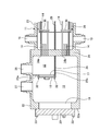
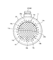
図1は、本実施形態の燃料ガス加熱器を表す縦断面図、図2は、燃料ガス加熱器を表す正面図、図3は、燃料ガス加熱器におけるガス流入室及びガス流出室を表す断面図、図4は、開閉蓋を取り外したガス流入室及びガス流出室を表す概略図である。
本実施形態の燃料ガス加熱器は、ガスタービンの燃焼器に供給される燃料ガスを加熱媒体としてのボイラ給水により所定の供給温度まで加熱するものである。
本実施形態において、図1から図4に示すように、燃料ガス加熱器10は、容器11と、ガス流入室12と、ガス流出室13と、複数の伝熱管14と、給水供給口(加熱媒体供給口)15と、給水排出口(加熱媒体排出口)16と、ガス流入室メンテナンス開口部17と、ガス流入室用開閉蓋18と、ガス流出室メンテナンス開口部19と、ガス流出室用開閉蓋20とを備えている。
容器11は、中空をなして水平方向に沿って長い形状をなして脚部21により横置きに配置され、長手方向における各端部が閉塞した円筒密閉形状をなしている。この容器11は、ガス給排部22と給水給排部23とが一体に形成されて構成されている。即ち、容器11は、内部に鉛直方向に沿う隔壁24が一体に設けられており、内部がガス給排部22側の第1空間部S1と、給水給排部23側の第2空間部S2とに区画されている。なお、ガス給排部22は、外径が給水給排部23の外径より大きく、第1空間部S1の内径が第2空間部S2の内径より大きな寸法となっている。
ガス給排部22は、容器11における長手方向の一端部に配置されており、第1空間部S1が仕切壁25によりガス流入室12とガス流出室13に区画されている。この仕切壁25は、鉛直壁25aと水平壁25bとがほぼ直角をなすように一体となったL字形状をなしている。この仕切壁25は、鉛直壁25aの上端部がガス給排部22(第1空間部S1)の天井部に接合され、水平壁25bの一端部が隔壁24に接合され、鉛直壁25a及び水平壁25bの各側端部がガス給排部22(第1空間部S1)の各側部に接合されている。そのため、ガス流入室12は、第1空間部S1の上方側で隔壁24に隣接して配置され、ガス流出室13は、第1空間部S1の下方側及びガス流入室12より容器11の端部側に配置される。
ガス給排部22は、上部に燃料ガスG1を流入するためのガス入口26が設けられると共に、加熱された燃料ガスG2を排出するガス出口27が設けられている。ガス入口26は、ガス流入室12に連通し、ガス出口27は、ガス流出室13に連通している。このガス入口26とガス流出室13は、ガス給排部22の上部で、容器11の長手方向(水平方向)に所定間隔を空けて並んで配置されている。
また、給水給排部23は、容器11における長手方向の他端部に配置されており、内部にU字形状をなす複数の伝熱管14が収容されている。この複数の伝熱管14は、一端部14a及び他端部14bが隔壁24に形成された支持孔に嵌合して支持されており、上方側の一端部14aがガス流入室12に連通し、下方側の他端部14bがガス流出室13に連通している。また、給水給排部23は、長手方向における隔壁24側にて、下部に第2空間部S2へボイラ給水W1を供給する給水供給口15が設けられると共に、上部に第2空間部S2内のボイラ給水W2を排出する給水排出口16が設けられている。給水供給口15と給水排出口16は、水平方向においてほぼ同位置に配置され、鉛直方向に対向している。
給水給排部23は、第2空間部S2における鉛直方向の中間部に仕切板28が水平をなして配置されている。仕切板28は、長手方向の一端部が隔壁24に連結され、他端部が容器11の長手方向の他端部の内壁面と所定隙間を空けて配置されている。仕切板28は、幅方向の各側部が容器11の内壁面に連結されている。給水給排部23は、第2空間部S2における各伝熱管14の外側に枠体29が配置され、枠体29は、給水給排部23の内壁面に支持されている。そして、仕切板28及び枠体29は、各伝熱管14の長手方向に所定間隔を空けて複数の邪魔板30,31が固定されている。給水給排部23内に収容された複数の伝熱管14は、この複数の邪魔板30,31により支持されている。この複数の邪魔板30,31は、第2空間部S2にて、鉛直方向に沿って配置されると共に、水平方向に所定間隔を空けて配置されている。この邪魔板30,31は、水平方向に交互に配置されると共に、鉛直方向にずれて配置されている。
そのため、ガス入口26からガス流入室12に流入した燃料ガスG1は、複数の伝熱管14の一端部14aから入り、この複数の伝熱管14内をU字状に流れた後、他端部14bからガス流出室13に排出され、ガス出口27から外部に排出される。一方、給水供給口15から給水給排部23内の第2空間部S2に供給されたボイラ給水W1は、第2空間部S2を仕切板28に沿って長手方向の一方側に流れた後、反転して長手方向の他方側に流れ、給水排出口16から外部に排出される。また、第2空間部S2に供給されたボイラ給水W1は、第2空間部S2で複数の邪魔板30,31を避けるようにジグザグに流れる。このとき、複数の伝熱管14内を流れる燃料ガスG1と、第2空間部S2内を移動するボイラ給水W1との間で熱交換が行われ、各伝熱管14内の燃料ガスG1がボイラ給水W1により加熱される。
第1空間部S1に配置される仕切壁25は、ガス流入室メンテナンス開口部17が設けられている。このガス流入室メンテナンス開口部17は、仕切壁25の鉛直壁25aに形成されており、ガス流入室12における各伝熱管14の一端部14aの連通位置に対向して設けられている。そして、ガス流入室メンテナンス開口部17は、ガス流入室用開閉蓋18により開閉可能となっている。ガス流入室用開閉蓋18は、複数の締結ボルト32により仕切壁25の鉛直壁25aに締結されている。この場合、ガス流入室メンテナンス開口部17の開口面積が、ガス流入室12における各伝熱管14の一端部14aが連通する領域の面積より大きな面積に設定されている。また、容器11の長手方向の一端部、つまり、ガス給排部22は、ガス流出室メンテナンス開口部19が設けられている。このガス流出室メンテナンス開口部19は、ガス給排部22の鉛直壁22aに形成されており、ガス流入室12における各伝熱管14の他端部14bの連通位置に対向して設けられている。そして、ガス流出室メンテナンス開口部19は、ガス流出室用開閉蓋20により開閉可能となっている。ガス流出室用開閉蓋20は、複数の締結ボルト33によりガス給排部22の鉛直壁22aに締結されている。この場合、ガス流出室メンテナンス開口部19の開口面積が、ガス流入室12における各伝熱管14の一端部14aが連通する領域の面積より大きな面積に設定されている。さらに、ガス流入室メンテナンス開口部17は、ガス流出室メンテナンス開口部19の一部に対向している。
そのため、ガス流入室用開閉蓋18及びガス流出室用開閉蓋20を取り外したとき、複数の伝熱管14は、各一端部14aがガス流入室メンテナンス開口部17及びガス流出室メンテナンス開口部19を通して容器11の外部に露出し、各他端部14bがガス流出室メンテナンス開口部19を通して容器11の外部に露出することとなる。
容器11は、ガス給排部22の下部にガス流出室13に漏洩した給水を排出するリーク水出口(漏洩熱媒体排出口)41が設けられ、一側部に連通口42が設けられている。リーク水出口41と連通口42とは、連通管43を介して連通している。そして、この連通管43にリーク水検出装置44が接続されている。このリーク水検出装置44は、連通管43の最下部と最上部とを連通する検査管45と、検査管45内でのリーク水の水位を計測する計測器46とから構成されている。
ここで、第2空間部S2内を移動するボイラ給水W1は、伝熱管14内を流れる燃料ガスG1よりも高温・高圧である。そのため、例えば、伝熱管14の一部が破損することで、第2空間部S2のボイラ給水W1が伝熱管14の破損から内部に浸入し、この伝熱管14を通してガス給排部22に流れ込む。すると、ガス給排部22に流れ込んだボイラ給水W1は、リーク水出口41から連通管43に流れ、連通管43に接続されている検査管45に流れる。このとき、計測器46が検査管45内のリーク水の水位を計測することで、伝熱管14からのボイラ給水W1のリーク(漏洩)を検出することができる。
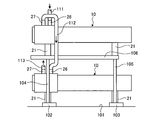
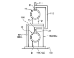
ところで、上述した燃料ガス加熱器10は、複数(本実施形態では、2個)が鉛直方向に沿って2段配置されている。図6は、本実施形態の燃料ガス加熱器の配置状態を表す側面図、図7は、燃料ガス加熱器の配置状態を表す正面図である。
図6及び図7に示すように、床面101に所定間隔を空けて2つの設置台102,103が設けられ、各設置台102,103上にそれぞれ2本の支持柱104,105が立設されており、支持台106がこの支持柱104,105により水平状態をなして支持されている。燃料ガス加熱器10は、各設置台102,103上に配置されて脚部21により支持されると共に、支持台106上に配置されて脚部21により支持されている。
上段側に配置された燃料ガス加熱器10は、ガス入口26にガス供給配管111が連結され、下段側に配置された燃料ガス加熱器10は、ガス出口27にガス排出配管113が連結されている。そして、上段側に配置された燃料ガス加熱器10のガス出口27と下段側に配置された燃料ガス加熱器10のガス入口26とがガス連結配管112により連結されている。この場合、ガス連結配管112は、支持柱104より支持柱105側で、且つ、支持台106より外側にて、鉛直方向に沿って配置されている。そして、ガス連結配管112は、上端部が水平方向及び鉛直方法に屈曲してから上段側の燃料ガス加熱器10のガス出口27に連結され、下端部が水平方向及び鉛直方法に屈曲してから下段側の燃料ガス加熱器10のガス入口26に連結されている。
即ち、燃料ガス加熱器10が重量物であり、特に、ガス給排部22の重量が重いことから、支持柱104とガス入口26及びガス出口27とが燃料ガス加熱器10の長手方向における位置がほぼ一致している。そのため、燃料ガス加熱器10の上部にガス入口26及びガス出口27を設け、ガス連結配管112を支持柱104や支持台106に干渉しないように配置している。
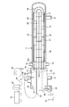
ここで、本実施形態の燃料ガス加熱器の洗浄方法について説明する。図5は、燃料ガス加熱器の洗浄方法を表す概略図である。
本実施形態の燃料ガス加熱器の洗浄装置は、コンプレッサ51と、ドレーン52と、サンドボックス53と、洗浄ノズル54と、回収箱55と、衝突板56と、集塵機57とを備えている。
本実施形態の燃料ガス加熱器の洗浄方法は、ガス流入室用開閉蓋18とガス流出室用開閉蓋20を取り外す工程と、洗浄ノズル54をガス流出室メンテナンス開口部19及びガス流入室メンテナンス開口部17を通してガス流入室12に挿入する工程と、洗浄ノズル54から伝熱管14の一端部14aに研掃材を注入する工程とを有している。また、本実施形態の燃料ガス加熱器の洗浄方法は、伝熱管14の他端部14bから排出された研掃材を衝突板56に衝突させて回収箱55に回収する工程を有している。
具体的に説明すると、図3に示すように、容器11のガス給排部22にて、まず、各ボルト33を弛緩してガス流出室用開閉蓋20を取り外した後、各締結ボルト32を弛緩してガス流入室用開閉蓋18を取り外す。すると、図4に示すように、容器11の外部から、ガス流出室メンテナンス開口部19を通してガス流出室13に露出する各伝熱管14の他端部14bを視認することができると共に、ガス流出室メンテナンス開口部19及びガス流入室メンテナンス開口部17を通してガス流入室12に露出する各伝熱管14の一端部14aを視認することができる。
次に、図5に示すように、コンプレッサ51にドレーン52及びサンドボックス53を介して洗浄ノズル54を連結する。また、ガス給排部22のガス流出室メンテナンス開口部19における下部側を閉塞するように、衝突板56を鉛直方向に沿って設置し、衝突板56の下方に回収箱55を載置し、集塵機57を連結する。ここで、ドレーン52は、圧縮空気の貯留部であり、サンドボックス53は、研掃材としてのカットワイヤの貯留部である。
この状態で、洗浄ノズル54をガス流出室メンテナンス開口部19及びガス流入室メンテナンス開口部17からガス流入室12に進入させ、ノズル先端部54aを伝熱管14の一端部14aに挿入する。ここで、各弁を開放することで、圧縮空気により洗浄ノズル54から伝熱管14内に研掃材を注入する。すると、研掃材は、一端部14aから伝熱管14内に注入され、内部を移動することで伝熱管14の内壁面に固着している異物を削り取る。そして、研掃材とこの研掃材により除去された異物は、伝熱管14の他端部14bから排出される。このとき、研掃材としてのカットワイヤは、棒状をなすことから、角部が伝熱管14の内壁面に固着している異物に衝突することで、伝熱管14の内壁面を損傷させることがなく、容易に固着した異物を削り取ることができる。また、伝熱管14の一端部14aから注入された研掃材は、U字形状をなす伝熱管14内を移動することで旋回することとなり、伝熱管14の内壁面に固着している異物を効率良く削り取ることができる。その後、伝熱管14の他端部14bから排出された研掃材と異物は、衝突板56に衝突した後に下降し、回収箱55に回収される。そして、回収箱55に回収された研掃材は、集塵機57により異物が除去されてから再利用される。
このように本実施形態の燃料ガス加熱器にあっては、中空形状をなす容器11と、容器11の一端部に区画されて燃料ガスのガス入口26を有するガス流入室12と、容器11の一端部に区画されて燃料ガスのガス出口27を有するガス流出室13と、容器11に収容されて一端部14aがガス流入室12に連通して他端部14bがガス流出室13に連通するU字形状をなす複数の伝熱管14と、容器11の内部にボイラ給水W1を供給する給水供給口15と、容器11の内部のボイラ給水W2を排出する給水排出口16と、ガス流入室12における伝熱管14の連通位置である一端部14aに対向して設けられるガス流入室メンテナンス開口部17と、ガス流入室メンテナンス開口部17を開閉可能なガス流入室用開閉蓋18と、ガス流出室13における伝熱管14の連通位置である他端部14bに対向して設けられるガス流出室メンテナンス開口部19と、ガス流出室メンテナンス開口部19を開閉可能なガス流出室用開閉蓋20とを設けている。
従って、容器11から各開閉蓋18,20を取り外すと、外部から伝熱管14の各端部14a,14bを視認することができ、洗浄ノズル54を伝熱管14の一端部14aに挿入して圧縮空気により研掃材を注入することで、伝熱管14の内部を移動する研掃材により伝熱管14の内壁面に固着している異物を削り取ることができる。その結果、伝熱管14のメンテナンスを短時間で容易に行うことができ、容器11や伝熱管14などの解体を不要としてメンテナンスコストを減少することができる。
本実施形態の燃料ガス加熱器では、容器11の内部を隔壁24により第1空間部S1と第2空間部S2とに区画し、第1空間部S1の上方側に隔壁24に隣接してガス流入室12を配置し、第1空間部S1の下方側及び容器11の端部側にガス流出室13を配置し、第2空間部S2に複数の伝熱管14を配置し、複数の伝熱管14の各端部14a,14bを隔壁24に貫通して設けている。従って、第1空間部S1の上方側にガス流入室12とガス流出室13を配置することで、燃料ガスのガス入口26やガス出口27を同じ側に設けることができ、製作コストを低減することができる。また、燃料ガスの主流ラインを上下方向に沿って配置することで、主流ラインにドレンノズル(水抜きライン)やベントノズル(ガス抜き)などを別途設ける必要がなくなり、構成を簡素化することができる。
本実施形態の燃料ガス加熱器では、ガス入口26及びガス出口27を容器11の上部に長手方向に並べて配置している。燃料ガス加熱器10を上下に複数配置する場合、下方側の燃料ガス加熱器10の各側方に柱や梁などの支持構造物が配置されることとなり、燃料ガス加熱器10の構造体を設けることが困難となる。従って、ガス入口26とガス出口27を容器11の上部に配置することで、ガス入口26やガス出口27に連結する配管を、支持柱104,105を避けて配置することができ、この配管を容易に配置することができ、構造の簡素化を可能とすることができる。
本実施形態の燃料ガス加熱器では、第1空間部S1を鉛直壁25a及び水平壁25bからなる仕切壁25により仕切ることで、ガス流入室12とガス流出室13を設け、ガス流出室メンテナンス開口部19を容器11の長手方向の一端部に設け、ガス流入室メンテナンス開口部17を鉛直壁25aに設けている。従って、ガス流出室メンテナンス開口部19とガス流入室メンテナンス開口部17を伝熱管14の各端部14a,14bに対向する位置に容易に設けることができる。
本実施形態の燃料ガス加熱器では、複数の伝熱管14の一端部14aをガス流入室メンテナンス開口部17及びガス流出室メンテナンス開口部19を通して容器11の外部に露出させ、他端部14bをガス流出室メンテナンス開口部19を通して容器11の外部に露出させている。従って、伝熱管14の各端部14a,14bを各メンテナンス開口部17,19を通して容易に容器11の外部に露出することができ、伝熱管14のメンテナンス作業の作業性を向上することができる。
本実施形態の燃料ガス加熱器では、容器11の下部にガス流出室13に漏洩したボイラ給水W2を排出するリーク水出口41を設けている。従って、伝熱管14の破損により第2空間部S2からガス流出室13に漏洩したボイラ給水W2を容易に外部に排出することができる。
本実施形態の燃料ガス加熱器では、リーク水出口41にリーク水検出装置44を接続している。従って、リーク水出口41からのボイラ給水W2の漏洩を検出することで、伝熱管14の破損を容易に検出することができる。また、ガス出口27を容器11の上部に配置しているので、ガス流出室13に漏洩したボイラ給水W2が、ガス出口27から排出されて燃焼器の燃料供給管へ流れてしまうことを防止することができる。
また、燃料ガス加熱器の支持構造物にあっては、床面101の設置台102,103に複数の支持柱104,105により支持台106を支持し、設置台102,103上及び支持台106上に燃料ガス加熱器10をそれぞれ設置し、ガス流入室12とガス流出室13の側方に支持柱104を配置している。
従って、燃料ガス加熱器10の重量がある部分の側方に支持柱104を配置し、ガス入口26及びガス出口27が側方に配置されていないことから、支持柱104を燃料ガス加熱器10に接近して配置することができ、支持構造物を合理的でコンパクトなものとすることができる。従来、燃料ガス加熱器10の第1空間部S1は、隔壁24が隣接しており、板厚が薄くて軽い伝熱管14の部分に比べて重量がある。本実施形態では、第1空間部S1の長さを長手方向に延長し、ガス流入室メンテナンス開口部17とガス流出室メンテナンス開口部19、並びにこれらを開閉可能な開閉蓋18,20が設置されるため、従来に比べて重量が増加する。この支持構造物では、大重量が作用する部分の荷重を合理的に受けられる構成であり、燃料ガス加熱器10や支持柱104,105を含む支持構造物の幅も狭くすることができ、2段の燃料ガス加熱器10の支持構造物を最もシンプルな構造物とすることができる。
また、本実施形態の燃料ガス加熱器の洗浄方法にあっては、ガス流入室用開閉蓋18とガス流出室用開閉蓋20を取り外す工程と、水平方向の長さがガス流入室12及びガス流出室13よりも長い洗浄ノズル54をガス流出室メンテナンス開口部19及びガス流入室メンテナンス開口部17を通してガス流入室12に挿入する工程と、洗浄ノズル54から伝熱管14の一端部14aに研掃材を注入する工程とを有している。
従って、容器11から各開閉蓋18,20を取り外すと、外部から伝熱管14の各端部14a,14bを視認することができ、洗浄ノズル54を伝熱管14の一端部14aに挿入して圧縮空気により研掃材を注入することで、伝熱管14の内部を移動する研掃材により伝熱管14の内壁面に固着している異物を削り取ることができる。その結果、伝熱管14のメンテナンスを短時間で容易に行うことができ、容器11や伝熱管14などの解体を不要としてメンテナンスコストを減少することができる。
また、本実施形態の燃料ガス加熱器の洗浄方法では、伝熱管14の他端部14bから排出された研掃材を衝突板56に衝突させて回収箱55に回収する工程を有している。従って、研掃材を容易に回収して再利用することができる。
なお、上述した実施形態では、燃料ガスのガス流入室12とガス流出室13の位置関係は、実施形態に限定されるものではなく、逆に配置してもよい。また、給水供給口(加熱媒体供給口)15と給水排出口(加熱媒体排出口)16の位置関係も逆にしてもよい。
10 燃料ガス加熱器
11 容器
12 ガス流入室
13 ガス流出室
14 伝熱管
15 給水供給口(加熱媒体供給口)
16 給水排出口(加熱媒体排出口)
17 ガス流入室メンテナンス開口部
18 ガス流入室用開閉蓋
19 ガス流出室メンテナンス開口部
20 ガス流出室用開閉蓋
22 ガス給排部
23 給水給排部
24 隔壁
25 仕切壁
26 ガス入口
27 ガス出口
41 リーク水出口(漏洩熱媒体排出口)
42 連通口
43 連通管
44 リーク水検出装置
45 検査管
46 計測器
51 コンプレッサ
52 ドレーン
53 サンドボックス
54 洗浄ノズル
55 回収箱
56 衝突板
57 集塵機
101 床面
102,103 設置台
104,105 支持柱
106 支持台
111 ガス供給配管
112 ガス連結配管
113 ガス排出配管
11 容器
12 ガス流入室
13 ガス流出室
14 伝熱管
15 給水供給口(加熱媒体供給口)
16 給水排出口(加熱媒体排出口)
17 ガス流入室メンテナンス開口部
18 ガス流入室用開閉蓋
19 ガス流出室メンテナンス開口部
20 ガス流出室用開閉蓋
22 ガス給排部
23 給水給排部
24 隔壁
25 仕切壁
26 ガス入口
27 ガス出口
41 リーク水出口(漏洩熱媒体排出口)
42 連通口
43 連通管
44 リーク水検出装置
45 検査管
46 計測器
51 コンプレッサ
52 ドレーン
53 サンドボックス
54 洗浄ノズル
55 回収箱
56 衝突板
57 集塵機
101 床面
102,103 設置台
104,105 支持柱
106 支持台
111 ガス供給配管
112 ガス連結配管
113 ガス排出配管
Claims (10)
- 中空形状をなして水平方向に沿って長い容器と、
前記容器における長手方向の一端部に区画されて燃料ガスのガス入口を有するガス流入室と、
前記容器における長手方向の一端部に区画されて燃料ガスのガス出口を有するガス流出室と、
前記容器の内部に設けられて一端部が前記ガス流入室に連通して他端部が前記ガス流出室に連通するU字形状をなす複数の伝熱管と、
前記容器の内部に加熱媒体を供給する加熱媒体供給口と、
前記容器の内部の加熱媒体を排出する加熱媒体排出口と、
前記ガス流入室における前記伝熱管の連通位置に対向して設けられるガス流入室メンテナンス開口部と、
前記ガス流入室メンテナンス開口部を開閉可能なガス流入室用開閉蓋と、
前記ガス流出室における前記伝熱管の連通位置に対向して設けられるガス流出室メンテナンス開口部と、
前記ガス流出室メンテナンス開口部を開閉可能なガス流出室用開閉蓋と、
を備えることを特徴とする燃料ガス加熱器。 - 前記容器は、内部が鉛直方向に沿う隔壁により第1空間部と第2空間部に区画され、前記第1空間部の上方側に前記隔壁に隣接して前記ガス流入室が配置され、前記第1空間部の下方側及び前記容器の端部側に前記ガス流出室が配置され、前記第2空間部に前記複数の伝熱管が配置され、前記複数の伝熱管の端部が前記隔壁を貫通して設けられることを特徴とする請求項1に記載の燃料ガス加熱器。
- 前記ガス入口及び前記ガス出口が前記容器の上部に前記容器の長手方向に並んで配置されることを特徴とする請求項2に記載の燃料ガス加熱器。
- 前記第1空間部は、鉛直方向に沿う鉛直壁及び水平方向に沿う水平壁からなる仕切壁により仕切られることで、前記ガス流入室と前記ガス流出室が設けられ、前記ガス流出室メンテナンス開口部は、前記容器の長手方向の一端部に設けられ、前記ガス流入室メンテナンス開口部は、前記鉛直壁に設けられることを特徴とする請求項2または請求項3に記載の燃料ガス加熱器。
- 前記複数の伝熱管は、一端部が前記ガス流入室メンテナンス開口部及び前記ガス流出室メンテナンス開口部を通して前記容器の外部に露出し、他端部が前記ガス流出室メンテナンス開口部を通して前記容器の外部に露出することを特徴とする請求項4に記載の燃料ガス加熱器。
- 前記容器は、下部に前記ガス流出室に漏洩した加熱媒体を排出する漏洩加熱媒体排出口が設けられることを特徴とする請求項1から請求項5のいずれか一項に記載の燃料ガス加熱器。
- 前記漏洩加熱媒体排出口に漏洩加熱媒体検出装置が接続されることを特徴とする請求項6に記載の燃料ガス加熱器。
- 床面に複数の支持柱により支持台が支持され、前記床面上及び前記支持台上に請求項3に記載の燃料ガス加熱器がそれぞれ設置され、
前記ガス流入室または前記ガス流出室の側方に前記支持柱が配置される、
ことを特徴とする燃料ガス加熱器の支持構造物。 - 中空形状をなして水平方向に沿って長い容器と、
前記容器における長手方向の一端部に区画されて燃料ガスのガス入口を有するガス流入室と、
前記容器における長手方向の一端部に区画されて燃料ガスのガス出口を有するガス流出室と、
前記容器の内部に設けられて一端部が前記ガス流入室に連通して他端部が前記ガス流出室に連通するU字形状をなす複数の伝熱管と、
前記容器の内部に加熱媒体を供給する加熱媒体供給口と、
前記容器の内部の加熱媒体を排出する加熱媒体排出口と、
前記ガス流入室における前記伝熱管の連通位置に対向して設けられるガス流入室メンテナンス開口部と、
前記ガス流入室メンテナンス開口部を開閉可能なガス流入室用開閉蓋と、
前記ガス流出室における前記伝熱管の連通位置に対向して設けられるガス流出室メンテナンス開口部と、
前記ガス流出室メンテナンス開口部を開閉可能なガス流出室用開閉蓋と、
を備える燃料ガス加熱器において、
前記ガス流入室用開閉蓋と前記ガス流出室用開閉蓋を取り外す工程と、
洗浄ノズルを前記ガス流出室メンテナンス開口部及び前記ガス流入室メンテナンス開口部を通して前記ガス流入室に挿入する工程と、
前記洗浄ノズルから前記伝熱管の一端部に研掃材を注入する工程と、
を有することを特徴とする燃料ガス加熱器の洗浄方法。 - 前記伝熱管の他端部から排出された研掃材を衝突板に衝突させて回収箱に回収する工程を有することを特徴とする請求項9に記載の燃料ガス加熱器の洗浄方法。
Priority Applications (3)
| Application Number | Priority Date | Filing Date | Title |
|---|---|---|---|
| KR1020197024247A KR102253217B1 (ko) | 2017-02-22 | 2018-01-17 | 연료 가스 가열기 및 연료 가스 가열기의 지지 구조물 및 연료 가스 가열기의 세정 방법 |
| DE112018000941.6T DE112018000941B4 (de) | 2017-02-22 | 2018-01-17 | Brennstoffgaserhitzer, Tragstruktur für Brennstoffgaserhitzer und Verfahren zum Reinigen des Brennstoffgaserhitzers |
| US16/486,698 US11143107B2 (en) | 2017-02-22 | 2018-01-17 | Fuel gas heater, support structure for fuel gas heater, and method for cleaning fuel gas heater |
Applications Claiming Priority (2)
| Application Number | Priority Date | Filing Date | Title |
|---|---|---|---|
| JP2017031022A JP6143985B1 (ja) | 2017-02-22 | 2017-02-22 | 燃料ガス加熱器及び燃料ガス加熱器の支持構造物並びに燃料ガス加熱器の洗浄方法 |
| JP2017-031022 | 2017-02-22 |
Publications (1)
| Publication Number | Publication Date |
|---|---|
| WO2018155015A1 true WO2018155015A1 (ja) | 2018-08-30 |
Family
ID=59012051
Family Applications (1)
| Application Number | Title | Priority Date | Filing Date |
|---|---|---|---|
| PCT/JP2018/001265 Ceased WO2018155015A1 (ja) | 2017-02-22 | 2018-01-17 | 燃料ガス加熱器及び燃料ガス加熱器の支持構造物並びに燃料ガス加熱器の洗浄方法 |
Country Status (5)
| Country | Link |
|---|---|
| US (1) | US11143107B2 (ja) |
| JP (1) | JP6143985B1 (ja) |
| KR (1) | KR102253217B1 (ja) |
| DE (1) | DE112018000941B4 (ja) |
| WO (1) | WO2018155015A1 (ja) |
Families Citing this family (2)
| Publication number | Priority date | Publication date | Assignee | Title |
|---|---|---|---|---|
| JP6143985B1 (ja) * | 2017-02-22 | 2017-06-07 | 三菱日立パワーシステムズ株式会社 | 燃料ガス加熱器及び燃料ガス加熱器の支持構造物並びに燃料ガス加熱器の洗浄方法 |
| JP7738496B2 (ja) * | 2022-02-04 | 2025-09-12 | 三菱重工業株式会社 | 熱交換器 |
Citations (5)
| Publication number | Priority date | Publication date | Assignee | Title |
|---|---|---|---|---|
| JPS63148067U (ja) * | 1987-03-19 | 1988-09-29 | ||
| US5544700A (en) * | 1994-08-22 | 1996-08-13 | General Electric Company | Method and apparatus for preferential cooling |
| JP2014137054A (ja) * | 2013-01-18 | 2014-07-28 | Mitsubishi Heavy Ind Ltd | 燃料ガス加熱器 |
| JP2014157001A (ja) * | 2013-02-18 | 2014-08-28 | Mitsubishi Heavy Ind Ltd | 熱交換器及びこれを備えたガスタービンプラント |
| JP6143985B1 (ja) * | 2017-02-22 | 2017-06-07 | 三菱日立パワーシステムズ株式会社 | 燃料ガス加熱器及び燃料ガス加熱器の支持構造物並びに燃料ガス加熱器の洗浄方法 |
Family Cites Families (15)
| Publication number | Priority date | Publication date | Assignee | Title |
|---|---|---|---|---|
| US1955015A (en) | 1932-04-07 | 1934-04-17 | Griscom Russell Co | Heat exchanger |
| US2520755A (en) * | 1948-09-13 | 1950-08-29 | Brown Fintube Co | Multiple tube heat exchanger |
| JPS5343615B2 (ja) | 1974-05-25 | 1978-11-21 | ||
| US3948315A (en) * | 1974-08-13 | 1976-04-06 | Brown Fintube Company | Closure for heat exchanger |
| US4142578A (en) * | 1977-09-12 | 1979-03-06 | Exxon Research & Engineering Co. | Heat exchanger impingement protection |
| JPS59196073A (ja) | 1983-04-22 | 1984-11-07 | Japan Organo Co Ltd | 冷凍魚肉すりみの製造法 |
| US4778005A (en) * | 1983-06-13 | 1988-10-18 | Exxon Research And Engineering Company | Baffle seal for sheel and tube heat exchangers |
| US4557322A (en) * | 1984-07-09 | 1985-12-10 | Kennedy Tank & Manufacturing Company, Inc. | Heat exchanger closure system |
| JPS63148067A (ja) | 1986-12-08 | 1988-06-20 | 松下電器産業株式会社 | ウオ−タ−ク−ラ |
| JP2000266494A (ja) | 1999-03-17 | 2000-09-29 | Usui Internatl Ind Co Ltd | 多管式熱交換器 |
| EP1357344B1 (en) | 2002-04-23 | 2008-11-12 | ExxonMobil Research and Engineering Company | Heat exchanger with floating head |
| US20040261395A1 (en) * | 2003-06-25 | 2004-12-30 | Engdahl Gerald E. | Reliable LNG vaporizer |
| JP2007255723A (ja) | 2006-03-20 | 2007-10-04 | Chiyuugai Technos Kk | スケールの除去方法およびその装置 |
| US9157685B2 (en) * | 2010-04-10 | 2015-10-13 | Christopher J. Dixon | Heat exchanger maintenance technique |
| JP2012007839A (ja) | 2010-06-25 | 2012-01-12 | Sumitomo Precision Prod Co Ltd | 熱交換器 |
-
2017
- 2017-02-22 JP JP2017031022A patent/JP6143985B1/ja active Active
-
2018
- 2018-01-17 WO PCT/JP2018/001265 patent/WO2018155015A1/ja not_active Ceased
- 2018-01-17 KR KR1020197024247A patent/KR102253217B1/ko active Active
- 2018-01-17 DE DE112018000941.6T patent/DE112018000941B4/de active Active
- 2018-01-17 US US16/486,698 patent/US11143107B2/en active Active
Patent Citations (5)
| Publication number | Priority date | Publication date | Assignee | Title |
|---|---|---|---|---|
| JPS63148067U (ja) * | 1987-03-19 | 1988-09-29 | ||
| US5544700A (en) * | 1994-08-22 | 1996-08-13 | General Electric Company | Method and apparatus for preferential cooling |
| JP2014137054A (ja) * | 2013-01-18 | 2014-07-28 | Mitsubishi Heavy Ind Ltd | 燃料ガス加熱器 |
| JP2014157001A (ja) * | 2013-02-18 | 2014-08-28 | Mitsubishi Heavy Ind Ltd | 熱交換器及びこれを備えたガスタービンプラント |
| JP6143985B1 (ja) * | 2017-02-22 | 2017-06-07 | 三菱日立パワーシステムズ株式会社 | 燃料ガス加熱器及び燃料ガス加熱器の支持構造物並びに燃料ガス加熱器の洗浄方法 |
Also Published As
| Publication number | Publication date |
|---|---|
| DE112018000941B4 (de) | 2024-10-17 |
| KR102253217B1 (ko) | 2021-05-17 |
| KR20190103431A (ko) | 2019-09-04 |
| JP6143985B1 (ja) | 2017-06-07 |
| JP2018135812A (ja) | 2018-08-30 |
| US20210285377A1 (en) | 2021-09-16 |
| US11143107B2 (en) | 2021-10-12 |
| DE112018000941T5 (de) | 2019-12-12 |
Similar Documents
| Publication | Publication Date | Title |
|---|---|---|
| CN106422586B (zh) | 一种带进气管的工业除尘器 | |
| JP6143985B1 (ja) | 燃料ガス加熱器及び燃料ガス加熱器の支持構造物並びに燃料ガス加熱器の洗浄方法 | |
| CN104548800B (zh) | 一种工业除尘器 | |
| CN105854436A (zh) | 高温烟气余热回收与袋式除尘一体化装置 | |
| CN103453537A (zh) | 一种湿烟囱顶部内筒壁外侧冷凝液收集装置 | |
| KR101339668B1 (ko) | 응축수 회수 장치 | |
| CN107337005B (zh) | 气箱脉冲袋式除尘器 | |
| CN105606525A (zh) | 一种多功能复合试验箱 | |
| KR101871907B1 (ko) | 모듈식의 전열관 열교환기 | |
| CN205867671U (zh) | 一种冷凝水储存集污零排气装置 | |
| KR102257988B1 (ko) | 기능이 개선된 집진장치 | |
| KR101194660B1 (ko) | 보일러 장치의 복합 분배기 및 이를 이용한 난방수 배관 세정방법 | |
| CN102557030B (zh) | 碳化硅冶炼炉尾气收集系统 | |
| CN202322725U (zh) | 一种干熄焦环形风道结构 | |
| CN211216027U (zh) | 一种高效型有机废气过滤装置 | |
| CN106969951A (zh) | 一种烟气连续自动监测系统中的防堵除湿采样设备 | |
| CN2899903Y (zh) | 采暖系统立式液体旋转除污过滤装置 | |
| RU2394184C2 (ru) | Утилизационный паровой котел сеня | |
| CN220017409U (zh) | 一种输灰系统过滤装置 | |
| CN106000252A (zh) | 多用途物料热解催化罐 | |
| RU2460569C1 (ru) | Способ модернизации сепарационного узла газового (варианты) и сепаратор газовый (варианты) | |
| RU2440173C2 (ru) | Газожидкостный сепаратор жалюзийного типа | |
| KR102388562B1 (ko) | 사이클론 집진기를 포함한 연소 시스템 | |
| KR100867332B1 (ko) | 난방,급탕 겸용 폐열회수장치 | |
| CN208465482U (zh) | 一种双室立体圆柱型高压喷淋除尘器 |
Legal Events
| Date | Code | Title | Description |
|---|---|---|---|
| 121 | Ep: the epo has been informed by wipo that ep was designated in this application |
Ref document number: 18758412 Country of ref document: EP Kind code of ref document: A1 |
|
| ENP | Entry into the national phase |
Ref document number: 20197024247 Country of ref document: KR Kind code of ref document: A |
|
| 122 | Ep: pct application non-entry in european phase |
Ref document number: 18758412 Country of ref document: EP Kind code of ref document: A1 |