WO2018150993A1 - 3軸力検出装置 - Google Patents
3軸力検出装置 Download PDFInfo
- Publication number
- WO2018150993A1 WO2018150993A1 PCT/JP2018/004327 JP2018004327W WO2018150993A1 WO 2018150993 A1 WO2018150993 A1 WO 2018150993A1 JP 2018004327 W JP2018004327 W JP 2018004327W WO 2018150993 A1 WO2018150993 A1 WO 2018150993A1
- Authority
- WO
- WIPO (PCT)
- Prior art keywords
- axis
- strain
- strain gauge
- force
- detection device
- Prior art date
- Legal status (The legal status is an assumption and is not a legal conclusion. Google has not performed a legal analysis and makes no representation as to the accuracy of the status listed.)
- Ceased
Links
Images




Classifications
-
- G—PHYSICS
- G01—MEASURING; TESTING
- G01L—MEASURING FORCE, STRESS, TORQUE, WORK, MECHANICAL POWER, MECHANICAL EFFICIENCY, OR FLUID PRESSURE
- G01L5/00—Apparatus for, or methods of, measuring force, work, mechanical power, or torque, specially adapted for specific purposes
- G01L5/16—Apparatus for, or methods of, measuring force, work, mechanical power, or torque, specially adapted for specific purposes for measuring several components of force
-
- A—HUMAN NECESSITIES
- A61—MEDICAL OR VETERINARY SCIENCE; HYGIENE
- A61H—PHYSICAL THERAPY APPARATUS, e.g. DEVICES FOR LOCATING OR STIMULATING REFLEX POINTS IN THE BODY; ARTIFICIAL RESPIRATION; MASSAGE; BATHING DEVICES FOR SPECIAL THERAPEUTIC OR HYGIENIC PURPOSES OR SPECIFIC PARTS OF THE BODY
- A61H7/00—Devices for suction-kneading massage; Devices for massaging the skin by rubbing or brushing not otherwise provided for
Definitions
- the present invention relates to a triaxial force detection device, and more particularly to a triaxial force detection device suitable for detecting a load and a load whose action point varies.
- a triaxial force sensor has been used for load detection.
- a triaxial force sensor is attached to an arm in a robot and is used to detect a reaction force load that acts on a machining tool when machining a workpiece (see, for example, Patent Document 1). .
- the component force in the other detection axis direction affects the detection value of the component force in one detection axis direction, and it is difficult to detect the load with high accuracy.
- the present invention has been made in view of the above-described problems, and an object of the present invention is to provide a three-axis force detection device that can detect a load more accurately than in the past.
- a triaxial force detection device includes a strain body portion having a pair of surfaces for receiving a load acting on an object, and the pair of strain body portions.
- An X-axis strain gauge attached to detect any X-axis direction force component on any of the surfaces, and a Y-axis direction force component detected on any of the pair of surfaces of the strain body
- a Y-axis strain gauge attached to detect a Z-axis direction force component with respect to any one of the pair of surfaces of the strain generating body portion.
- a triaxial force sensor a bending sensor for detecting a position where the load acts on the object, and a signal processing unit electrically connected to the bending sensor and the triaxial force sensor,
- the signal processing unit is based on detection signals of the bending sensor and the three-axis force sensor.
- X-axis direction force component of the load Y-axis direction force component of the load, and calculates the Z-axis direction force component of the load, it is characterized.
- the signal processing unit is configured so that the object is supported between a portion where the member supporting the object is supported and the object based on a detection signal of the bending sensor. The distance in the Z-axis direction is calculated.
- the X-axis strain gauge, the Y-axis strain gauge, and the Z-axis strain gauge are provided on one of the pair of surfaces of the strain body portion. It is attached.
- each of the X-axis strain gauge, the Y-axis strain gauge, and the Z-axis strain gauge has a grid length of the pair of strain-generating body portions. Are arranged in a direction in which distortion appearing on one of the surfaces is obtained as a change in voltage.
- any two of the X-axis strain gauge, the Y-axis strain gauge, and the Z-axis strain gauge are the pair of surfaces of the strain body portion.
- the remaining one of the X-axis strain gauge, the Y-axis strain gauge, and the Z-axis strain gauge is attached to the other of the pair of surfaces of the strain generating body portion.
- each of the two of the X-axis strain gauge, the Y-axis strain gauge, and the Z-axis strain gauge has a grid length that is greater than that of the first.
- the strain appearing on one of the pair of surfaces of the strain body portion is arranged in a direction obtained as a change in voltage, and the X-axis strain gauge, the Y-axis strain gauge, and the Z-axis strain gauge The remaining one is arranged in such a direction that the grid length can be obtained as a change in voltage with the strain appearing on the other of the pair of surfaces of the strain generating body portion.
- the bending sensor is a sensor for detecting a moment around the X axis.
- the strain body portion is separated from the object in the Y-axis direction and includes the pair of surfaces on a plane including the X-axis and the Z-axis.
- the bending sensor is spaced apart from the position where the load acts on the object in the Z-axis direction.
- the three-axis force detection device According to the three-axis force detection device according to the present invention, it is possible to detect the load with higher accuracy than in the past.
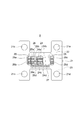
- FIG. It is a figure for showing the composition of the 3 axis force sensor with which the 3 axis force detection device concerning a 2nd embodiment of the present invention is provided, Drawing 5 (A) is a top view, and Drawing 5 (B) is the back.
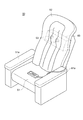
- FIG. It is an external appearance perspective view which shows the whole structure of the massage machine to which the triaxial force detection apparatus which concerns on the 1st Embodiment of this invention is applied. It is a rough-line perspective view which shows the structure of the treatment unit in the massage machine shown in FIG. It is a perspective view which shows the structure of the support arm in the massage machine shown in FIG.
- Drawing 9 (A) is a perspective view
- Drawing 9 (B) is a rear view. It is a perspective view which shows the triaxial force sensor attached to the massage machine shown in FIG.
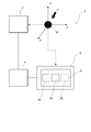
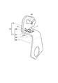
- FIG. 1 is a diagram schematically showing a configuration of a three-axis force detection device 1 according to a first embodiment of the present invention.
- the triaxial force detection device 1 includes a triaxial force sensor 2, a bending sensor 3, and a signal processing unit 4.
- the triaxial force sensor 2 includes a strain body 21 for receiving a load F acting on the object W, and an X axis strain gauge attached to the strain body 21 to detect an X-axis direction force component. 24, a Y-axis strain gauge 25 attached to the strain body 21 for detecting the Y-axis direction force component, and a Z attached to the strain body 21 for detecting the Z-axis direction force component. And an axial strain gauge 26.
- the triaxial force sensor 2 includes a detection value DFx corresponding to the force component of the load F in the X-axis direction (force component Fx), a detection value DFy corresponding to the force component of the load F in the Y-axis direction (force component Fy), and the load F
- the bending sensor 3 is a sensor for detecting a position where the load F acts on the target object W.
- the bending sensor 3 is a sensor that outputs a detection value DFz corresponding to the Z-axis direction force component (force component Fz).
- the strain body 21 has a pair of surfaces, and the X-axis strain gauge 24 is attached to one of the pair of surfaces of the strain body 21 and is used for the Y-axis.
- the strain gauge 25 is attached to any one of the pair of surfaces of the strain body 21, and the Z-axis strain gauge 26 is attached to any one of the pair of surfaces of the strain body 21. .
- FIG. 2 is a plan view showing the configuration of the triaxial force sensor 2 in the triaxial force detection device 1.
- the X-axis strain gauge 24, the Y-axis strain gauge 25, and the Z-axis strain gauge 26 are attached to one of the pair of surfaces (surface 22) of the strain body 21.
- the strain in which each grid length appears on one of the pair of surfaces (surface 22) of the strain generating body portion 21 is changed in voltage. It is arranged in the direction obtained as
- the strain body 21 is a member made of a plate-like diaphragm having an overall H shape, and has a front surface 22 and a back surface 23 that are a pair of surfaces. .
- the front surface 22 and the back surface 23 are planes facing each other or substantially planar surfaces.
- the X-axis strain gauge 24, the Y-axis strain gauge 25, and the Z-axis strain gauge 26 are concentrated in the center of the surface 22, which is one of the pair of surfaces of the strain body 21.
- the strain body 21 is provided with mounting holes 21a to 21d which are through holes for mounting to other members at the four corners. These mounting holes 21a to 21d are arranged at positions corresponding to mounting holes formed in other members. Aluminum alloy, alloy tool steel, stainless steel, ceramic, resin, plastic, or the like is used as the material of the strain generating body portion 21 and bends according to the direction and strength of the load received by the object W.
- the X-axis strain gauge 24 is a sensor for detecting a force component Fx in the X-axis direction of the load F acting on the object W, and has, for example, four strain gauges 24a to 24d.
- the Y-axis strain gauge 25 is a sensor for detecting a force component Fy in the Y-axis direction of the load F acting on the object W, and has, for example, four strain gauges 25a to 25d.
- the Z-axis strain gauge 26 is a sensor for detecting a force component Fz in the Z-axis direction of the load F acting on the object W, and has, for example, four strain gauges 26a to 26d.
- the strain gauges 24a to 24d, 25a to 25d, and 26a to 26d are attached to the surface 22 of the strain generating body portion 21 by being attached thereto.
- the strain gauges 24a to 24d of the X-axis strain gauge 24 are forces transmitted through other members to which the strain-generating body portion 21 is attached in use when a load in the X-axis direction is applied to the object W. Therefore, the surface 22 of the strain generating body portion 21 is disposed at the most distorted portion.
- the strain gauges 24a to 24d of the strain gauge 24 for X-axis provide a grid of wiring patterns in the strain gauges 24a to 24d so that the strain appearing on the surface 22 of the strain generating body 21 can be obtained most efficiently as a change in voltage.
- the lengths (gauge lengths) are arranged in a state in which the respective directions are matched with predetermined directions. For example, as shown in FIG.
- the strain gauges 24a and 24d are arranged so that the grid lengths face in the same direction
- the strain gauges 24b and 24c are arranged so that the grid lengths face in the same direction
- the gauges 24a and 24d are arranged such that the direction of each grid length is orthogonal to the direction of each grid length of the strain gauges 24b and 24c.
- the strain gauges 25a to 25d of the Y-axis strain gauge 25 are configured to generate a strain-generating body by a force transmitted to the strain-generating body portion 21 through another member when a load in the Y-axis direction is applied to the object W.
- the surface 22 of the portion 21 is disposed at the most distorted portion.
- the strain gauges 25a to 25d of the Y-axis strain gauge 25 are divided into left and right (upper side in FIG. 2) around the X-axis strain gauge 24, and the strain gauges 25a and 25b are located on the left side in FIG.
- the strain gauges 25c and 25d are arranged on the right side in FIG.
- the strain gauges 25a to 25d of the Y-axis strain gauge 25 have a wiring pattern grid in the strain gauges 25a to 25d so that the strain appearing on the surface 22 of the strain generating body 21 can be obtained most efficiently as a change in voltage. They are arranged in a state in which the long directions are respectively matched with predetermined directions. For example, as shown in FIG. 2, the strain gauges 25a to 25d are arranged so that the grid lengths are all directed in the same direction, and the strain gauges 25a to 25d are the strain gauges 24a to 24d of the X-axis strain gauge 24. Each grid length is arranged in a direction having an angle difference of 45 degrees or about 45 degrees with respect to the grid length direction.
- the strain gauges 26a to 26d of the Z-axis strain gauge 26 are configured to generate a strain-generating body by a force transmitted to the strain-generating body portion 21 via another member when a load in the Z-axis direction is applied to the object W.
- the surface 22 of the portion 21 is disposed at the most distorted portion.
- the strain gauges 26 a to 26 d of the Z-axis strain gauge 26 are disposed between the X-axis strain gauge 24 and the strain gauges 25 a and 25 b of the Y-axis strain gauge 25. That is, the strain gauges 26a to 26d of the Z-axis strain gauge 26 are disposed adjacent to the left side of the X-axis strain gauge 24 in FIG.
- the strain gauges 26a to 26d of the Z-axis strain gauge 26 have a wiring pattern grid in the strain gauges 26a to 26d so that the strain appearing on the surface 22 of the strain generating body portion 21 can be obtained most efficiently as a change in voltage. They are arranged in a state in which the long directions are respectively matched with predetermined directions. For example, as shown in FIG. 2, the strain gauges 26a and 26c are arranged so that the grid lengths are oriented in the same direction, and the strain gauges 26b and 26d are arranged so that the grid lengths are oriented in the same direction. The strain gauges 26b and 26d are arranged such that the grid lengths are oriented in a direction perpendicular to the orientation of the grid lengths of the strain gauges 26a and 26c.
- the strain gauges 24a to 24d of the X-axis strain gauge 24, the strain gauges 25a to 25d of the Y-axis strain gauge 25, and the strain gauges 26a to 26d of the Z-axis strain gauge 26 are bonded for sensor output extraction.
- the pad 27 is electrically connected.
- the bonding pad 27 is electrically connected to the signal processing unit 4, and detected values of the X axis strain gauge 24, the Y axis strain gauge 25, and the Z axis strain gauge 26. Can be transmitted to the signal processing unit 4.
- the triaxial force sensor 2 In the use state in which the triaxial force detection device 1 is used to detect the load F acting on the object W, the triaxial force sensor 2 has the strain body 21 with respect to the object W.
- the front surface 22 and the rear surface 23 which are a pair of surfaces are arranged along a plane including the X axis and the Z axis so as to be separated from each other in the Y axis direction.
- the triaxial force sensor 2 is arranged so that the surface 22 of the strain generating body portion 21 faces the object W in use and the Z axis is directed from the left side to the right side in FIG.
- the grid lengths of the strain gauges 24a and 24d of the X axis strain gauge 24 extend with an inclination of 135 degrees or substantially 135 degrees from the Z axis
- the grid lengths of the strain gauges 24b and 24c of the gauge 24 extend with an inclination of 45 degrees or approximately 45 degrees from the Z axis.
- the grid lengths of the strain gauges 25a to 25d of the Y-axis strain gauge 25 extend parallel to or substantially parallel to the Z axis.
- the grid lengths of the strain gauges 26a, 26c of the Z-axis strain gauge 26 extend in parallel or substantially parallel to the Z-axis, and the grid lengths of the strain gauges 26b, 26d of the Z-axis strain gauge 26 are , Extending parallel to or substantially parallel to the X axis.
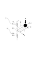
- FIG. 3 is a schematic diagram for schematically showing the configuration of the bending sensor 3.
- the bending sensor 3 is a sensor for detecting a bending moment M (Fy) around the X axis generated by a component force Fy that is a Y-axis direction force component of the load F acting on the object W, and more specifically. Is the moment M (Fy) at the part (part 36 in FIG. 3) where the member (part 35 in FIG. 3) that supports the object W is supported in the member or apparatus in which the triaxial force detection device 1 is used. It is a sensor for detecting. Based on the moment M (Fy) detected by the bending sensor 3, a distance L that is a distance in the Z-axis direction between the part 36 and the object W can be calculated.
- the bending sensor 3 may have any configuration that can detect the moment M (Fy), and includes any known bending sensor that can detect the moment M (Fy).
- the bending sensor 3 includes four strain gauges 31 to 34.
- the strain gauges 31 to 34 are planes (substantially planes) parallel to the plane including the Y axis and the X axis. Thus, they are arranged side by side in the Y-axis direction on the plane including the portion 36.
- the strain gauges 31 and 32 are on one side (upper side in FIG. 3) with respect to the object W in the Y-axis direction, and the strain gauges 33 and 34 are on the other side with respect to the object W in the Y-axis direction. (Lower side in FIG. 3).
- the signal processing unit 4 Based on the moment M (Fy) value that is the detection value of the bending sensor 3, the signal processing unit 4 detects the detected value DFx and the force component of the load F according to the force component Fx of the load F output from the triaxial force sensor 2.
- the detection value DFy corresponding to Fy and the detection value DFz corresponding to the force component Fz of the load F are corrected.
- the correction process executed by the signal processing unit 4 is a process for reducing or removing interference of the force component in the other axial direction with respect to the detection value corresponding to the force component in one axial direction.
- the detected values DFx, DFy, DFz, DFx, DFy, DFz, DFx, DFy, DFz are calculated by performing a calculation process on the moment M (Fy) and the detected values DFx, DFy, DFz. DFz is corrected.
- the previously prepared correction data P is, for example, matrix data or map data.
- the signal processing unit 4 has matrix data as the correction data P.
- the correction data P is 4 ⁇ 4 matrix data, and each value of the matrix data is a value obtained in advance.
- the correction process is a process of integrating the matrix data and the detection values M (Fy), DFx, DFy, and DFz, and is corrected by the product of the matrix data and the detection values M (Fy), DFx, DFy, and DFz. Detection values of force components Fx, Fy, and Fz of the load F are calculated.
- correction processing in the signal processing unit 4 it is possible to accurately detect the values of the force components Fx, Fy, and Fz of the load F in which interference of other force components is reduced.
- the load W can be detected with higher accuracy than in the prior art.
- FIG. 4 is a diagram schematically showing the configuration of the three-axis force detection device 5 according to the second embodiment of the present invention.
- the three-axis force detection device 5 according to the second embodiment of the present invention is 3 in comparison with the above-described three-axis force detection device 1 according to the first embodiment of the present invention.
- the structure of the axial force sensor is different.
- components having the same or similar functions as those of the above-described three-axis force detection device 1 according to the first embodiment of the present invention will be denoted by the same reference numerals, description thereof will be omitted, and different portions will be described. .
- FIG. 5 is a diagram for illustrating the configuration of the triaxial force sensor 6 provided in the triaxial force detection device 5, FIG. 5 (A) is a plan view, and FIG. 5 (B) is a rear view.
- an X-axis strain gauge 24 (strain gauges 24a to 24d) that detects a force component Fx in the X-axis direction of the load F acting on the object W.
- the Y-axis strain gauge 25 strain gauges 25a to 25d
- the Z-axis strain gauges 26 (26a to 26d) for detecting the force component Fz in the Z-axis direction of the load F acting on the object W are, as shown in FIG. Attached to the back surface 23.
- the X-axis strain gauge 24 (strain gauges 24a to 24d) is configured so that the strain body 21 is in use when a load in the X-axis direction is applied to the object W.
- the surface 22 of the strain generating body portion 21 is disposed at the portion where the distortion is the largest due to the force transmitted through the other member to be attached.
- the strain gauges 25a to 25d of the Y-axis strain gauge 25 are configured to generate a strain-generating body by a force transmitted to the strain-generating body portion 21 through another member when a load in the Y-axis direction is applied to the object W.
- the surface 22 of the portion 21 is disposed at the most distorted portion.
- the strain gauges 26a to 26d of the Z-axis strain gauge 26 are subjected to strain generation via other members when a load in the Z-axis direction is applied to the object W on the back surface 23 of the strain generating body portion 21. Due to the force transmitted to the body part 21, the back surface 23 of the strain generating body part 21 is arranged at the most distorted part.
- the X-axis strain gauge 24, the Y-axis strain gauge 25, and the Z-axis strain gauge 26 are allocated to the front surface 22 and the back surface 23 of the strain generating body portion 21. Arranged. As a result, the degree of freedom of the arrangement of the strain gauges 24 to 26 is increased, and the strain is distorted at the optimum position where the largest sensor output can be obtained without worrying about the overlap in the arrangement of the strain gauges 24, 25 and the strain gauge 26. Gauges 24 to 26 can be attached respectively.
- each of the strain gauges 24a to 24d of the X-axis strain gauge 24 is the same as that of the above-described triaxial force sensor 2, and each strain of the Y-axis strain gauge 25 is also the same.
- the directions of the grid lengths of the gauges 25a to 25d are the same as those of the triaxial force sensor 2 described above.
- the relative position between the X-axis strain gauge 24 (strain gauges 24a to 24d) and the Y-axis strain gauge 25 (strain gauges 25a to 25d) is also the same as that of the above-described three-axis force sensor 2. .
- the grid length of the strain gauges 26a to 26d of the Z-axis strain gauge 26 can obtain the strain appearing on the back surface 23 of the strain generating body portion 21 as the change in voltage most efficiently in the second embodiment of the present invention. So that direction is turned.
- the inner strain gauges 26 a and 26 c of the strain gauges 26 a to 26 d of the Z-axis strain gauge 26 are one of the inner sides of the back surface 23 of the strain generating body portion 21.
- the strain gauges 26b and 26d are disposed on the other side (the right side in FIG. 5B) than the center of the back surface 23 of the strain generating body portion 21 is disposed on the side (the left side in FIG. 5B). ing.
- the grid lengths of the strain gauges 26a to 26d are all directed in the same direction, and the strain gauges 26a to 26d are arranged so that the grid lengths are in the X-axis direction (vertical direction in FIG. 5B) when in use. Has been.
- the strain gauges 26a to 26d of the Z-axis strain gauge 26 are electrically connected to the bonding pads 28 for taking out sensor outputs on the back surface 23, respectively.
- the three-axis force detection device 5 also operates in the same manner as the above-described three-axis force detection device 1, and the interference of other force components is reduced by the correction processing in the signal processing unit 4.
- the value of each force component Fx, Fy, Fz of the applied load F can be detected with high accuracy.
- the X axis strain gauge 24, the Y axis strain gauge 25, and the Z axis strain gauge 26 in the triaxial force sensor 6 are compared to the above triaxial force sensor 2.
- the triaxial force detection device 5 detects the force components Fx, Fy, and Fz of the load F with higher accuracy than the triaxial force detection device 1 described above. Can do.
- the load W can be detected with higher accuracy than in the prior art.
- the X-axis strain gauge 24 and the Y-axis strain gauge 25 are placed on the surface 22 of the strain-generating body portion 21, and the Z-axis strain gauge 25. 26 is attached to the back surface 23 of the strain generating body portion 21, but the arrangement positions of the strain gauges 24 to 26 for each axis are not limited to this.
- any two of the X-axis strain gauge 24, the Y-axis strain gauge 25, and the Z-axis strain gauge 26 are one of a pair of surfaces of the strain generating body portion 21.
- the remaining one of the X-axis strain gauge 24, the Y-axis strain gauge 25, and the Z-axis strain gauge 26 is attached to the back surface 23, which is the other of the pair of surfaces of the strain-generating body portion 21. It may be attached.
- the massage machine 50 is a sitting chair type electric massage machine, and includes a seat part 51 having armrest parts 51 a and 51 a on both sides in the width direction, and a rear end part of the seat part 51 upward. And a backrest portion 52 that is erected.
- the backrest portion 52 is provided with a treatment unit 60 having two kneading balls 53 therein.
- the treatment unit 60 is provided with two treatment unit supports 63, 63 integrally with a frame plate 61 attached to the support shaft 62, and with respect to the treatment unit supports 63, 63.
- the sensor structure 70 to which the kneading balls 53 as the object W are attached is fixed.
- the sensor structure 70 includes a support arm 71 and a shaft support cover 75 attached to the vertical portion 69 at the tip of the support arm 71.
- the support arm 71 is, for example, a metallic plate-like member formed to extend from the treatment unit support 63 so as to be separated from the treatment unit support 63.
- the support arm 71 includes an arm portion 66 extending from the treatment unit support 63, a horizontal portion 67 extending in the horizontal direction in the drawing so as to be substantially orthogonal to the arm portion 66, and the arm portion 66 and the horizontal portion 67.
- a curved portion 68 that is integrally connected at an angle of 90 degrees and a vertical portion 69 that extends in the vertical direction from the tip of the horizontal portion 67 so as to be substantially orthogonal to the horizontal portion 67 are provided.
- the arm portion 66 is fixed to the treatment unit support 63 of the treatment unit 60.
- the horizontal portion 67 is a portion connecting the arm portion 66 and the vertical portion 69, which is bent away from the shaft support cover 75 attached integrally with the vertical portion 69, and is a grudge attached via the shaft support cover 75. Although it has a flat surface 67 a that faces the outer peripheral surface of the ball 53, it does not come into contact with the kneading ball 53. Further, the horizontal portion 67 is formed with a through hole 67h.
- the vertical portion 69 of the support arm 71 is a portion to which a shaft support cover 75 as a holding body that holds the kneading balls 53 is integrally attached. In FIG. The part 69 is in a hidden state.
- the shaft support cover 75 includes a cover main body 76 and a shaft portion 54 that is integrally attached to a flat support plate 77 of the cover main body 76.
- the kneading balls 53 are held in a state where they are pivotally supported with respect to the shaft portion 54. Therefore, the shaft support cover 75 can move the kneading balls 53 freely in the three-dimensional X-axis direction, Y-axis direction, and Z-axis direction as shown in FIG. 8 according to the external load on the kneading balls 53. Hold.
- the cover body 76 includes a partition wall 78 that is erected from the periphery of the support plate 77 perpendicular to the support plate 77.
- the partition wall 78 is not erected over the entire periphery of the support plate 77 but has an opening 78 h having a size corresponding to the width of the vertical portion 69 of the support arm 71.
- the support plate 77 of the cover body 76 is provided with screw through holes 76 a, 76 b, 76 c around the support plate 77 for attaching the cover body 76 to the vertical portion 69 of the support arm 71 by screwing.
- the support plate 77 is provided with a mounting hole 76h penetrating at a position separated from the screw through holes 76a and 76c by substantially the same distance.
- the shaft portion 54 directly supports the kneading balls 53 and receives a load on the kneading balls 53, and the shaft portion 54 extends from the support plate 77 with the base portion connected to the connection portion 77 a of the support plate 77. .
- the shaft portion 54 has the same outer diameter as the inner diameter of the shaft hole (not shown) of the kneading balls 53 and has a predetermined length that can support the kneading balls 53.
- a kneading ball 53 is rotatably fixed to the shaft portion 54.
- connection part 77a of the support plate 77 is a disk-shaped part having a predetermined thickness, and extends to the outer peripheral side from the shaft part 54.
- the shaft portion 54 bends according to the direction and strength of the load received through the kneading balls 53 and functions as a diaphragm.
- the massage machine 50 does not have the shaft support cover 75, and the shaft portion 54 may be formed directly with respect to the vertical portion 69 of the support arm 71. In this case, the connecting portion 77a is formed in the vertical portion 69.
- the bending sensor 3 is attached to the back surface side of the support plate 77 of the shaft support cover 75, not the shaft portion 54 side of the connection portion 77a, and the strain gauges 31 to 34 are shown in FIG. As shown in FIG. 2, they are mounted side by side in the Y-axis direction. That is, the shaft portion 54 corresponds to the member 35 in FIG. 3, and the portion 36 in FIG. 3 exists in the connection portion 77a. As shown in FIG. 10, the triaxial force sensor 2 is fixed to the horizontal portion 67 so as to cover a rectangular through hole 67 h formed in the horizontal portion 67 of the support arm 71.
- the through-hole 67h formed in the horizontal portion 67 of the support arm 71 is a hole necessary for the influence of the load on the kneading balls 53 to easily appear as distortion in the horizontal portion 67.
- the horizontal portion 67 is intentionally used. Is provided in order to reduce the strength.
- the through hole 67h has a rectangular shape with a predetermined size, but is not limited thereto, and the size and shape are set according to the strength of the horizontal portion 67 and the sensitivity of the sensor output of the triaxial force sensor 2. .
- the load F acting on the kneading balls 53 as the object W is transmitted to the horizontal portion 67 through the shaft portion 54, the shaft support cover 75, and the vertical portion 69 of the support arm 71.
- the transmission force of the load F transmitted in this way is applied to the horizontal portion 67, and the load F appears as strain (deflection) in the strain body 21 of the triaxial force sensor 2 fixed to the horizontal portion 67.
- a bending moment around the X-axis is generated at the connecting portion 77 a of the shaft support cover 75 by the load F (force component Fy) acting on the kneading balls 53.
- the distance in the Z-axis direction between the position where the load F acts on the kneading balls 53 and the connecting portion 77a corresponds to the distance L shown in FIG.
- the triaxial force detection device 1 operates as described above, the bending sensor 3 detects the moment M (Fy), and the triaxial force sensor 2 corresponds to the force components Fx, Fy, and Fz of the load F, respectively. Detected values DFx, DFy, DFz are output, and the detected values DFx, DFy, DFz are corrected by the signal processing unit 4 performing calculation processing on these moments M (Fy) and detected values DFx, DFy, DFz. Is done. Thereby, each force component Fx, Fy, Fz of the load F in which interference of other force components is reduced can be detected with high accuracy.
- the present invention is not limited to the three-axis force detection devices 1 and 5 according to the above-described embodiments, and is within the concept of the present invention and the claims. Includes all included aspects.
- the configurations may be appropriately combined as appropriate so as to achieve at least part of the problems and effects described above.
- the shape, material, arrangement, size, and the like of each component in the above embodiment can be changed as appropriate according to the specific usage mode of the present invention.
Landscapes
- Health & Medical Sciences (AREA)
- General Physics & Mathematics (AREA)
- Physics & Mathematics (AREA)
- Life Sciences & Earth Sciences (AREA)
- Physical Education & Sports Medicine (AREA)
- Rehabilitation Therapy (AREA)
- Pain & Pain Management (AREA)
- Animal Behavior & Ethology (AREA)
- General Health & Medical Sciences (AREA)
- Public Health (AREA)
- Veterinary Medicine (AREA)
- Epidemiology (AREA)
- Dermatology (AREA)
- Force Measurement Appropriate To Specific Purposes (AREA)
Abstract
荷重を従来に比べて精度良く検出することができる3軸力検出装置を提供する。 3軸力検出装置(1)は、3軸力センサ(2)と、曲げセンサ(3)と、信号処理部とを備えている。3軸力センサ(2)は、対象物(W)に作用する荷重(F)を受けるための起歪体部(21)と、起歪体部(21)に取り付けられた、X軸方向力成分を検出するX軸用歪ゲージ(24)と、Y軸方向力成分を検出するY軸用歪ゲージ(25)と、Z軸方向力成分を検出するZ軸用歪ゲージ(26)とを備えている。3軸力センサ(2)は、荷重(F)の力成分(Fx, Fy, Fz)に応じた検出値(DFx, DFy, DFz,)を出力するセンサであり、曲げセンサ(3)は、荷重(F)が対象物(W)に作用する位置を検出するためのセンサである。信号処理部(4)は曲げセンサ(3)及び3軸力センサ(2)に電気的に接続されており、曲げセンサ(3)及び3軸力センサ(2)の検出信号に基づいて、荷重のX軸方向力成分、Y軸方向力成分、及びZ軸方向力成分を算出する。
Description
本発明は、3軸力検出装置に関し、特に、荷重及びその作用点が変動する荷重の検出に好適な3軸力検出装置に関する。
従来から、荷重の検出のために3軸力センサが使用されている。例えば、3軸力センサは、ロボットにおいて、アームに取り付けられて、ワークを加工する際に加工ツールに作用する反力荷重を検出するために用いられている(例えば、特許文献1を参照。)。
しかしながら、従来の3軸力センサでは、1つの検出軸方向の分力の検出値に他の検出軸方向の分力が影響してしまうため、荷重を精度良く検出することが困難であった。
このように、従来から、多様な方向から加えられる荷重を精度良く検出することができる3軸力検出装置が求められていた。
本発明は、上述の課題に鑑みてなされたものであり、その目的は、荷重を従来に比べて精度良く検出することができる3軸力検出装置を提供することにある。
上述の目的を達成するために、本発明に係る3軸力検出装置は、対象物に作用する荷重を受けるための一対の面を有する起歪体部と、該起歪体部の前記一対の面のいずれかに対してX軸方向力成分を検出するために取り付けられたX軸用歪ゲージと、前記起歪体部の前記一対の面のいずれかに対してY軸方向力成分を検出するために取り付けられたY軸用歪ゲージと、前記起歪体部の前記一対の面のいずれかに対してZ軸方向力成分を検出するために取り付けられたZ軸用歪ゲージとを備える3軸力センサと、前記荷重が前記対象物に作用する位置を検出するための曲げセンサと、前記曲げセンサ及び前記3軸力センサに電気的に接続された信号処理部と、を備え、前記信号処理部は、前記曲げセンサ及び前記3軸力センサの検出信号に基づいて、前記荷重のX軸方向力成分、前記荷重のY軸方向力成分、及び前記荷重のZ軸方向力成分を算出する、ことを特徴とする。
本発明の一態様に係る3軸力検出装置において、前記信号処理部は、前記曲げセンサの検出信号に基づいて、前記対象物を支持する部材が支持される部位と前記対象物との間のZ軸方向における距離を算出する。
本発明の一態様に係る3軸力検出装置において、前記X軸用歪ゲージ、前記Y軸用歪ゲージ、及び前記Z軸用歪ゲージは、前記起歪体部の前記一対の面の一方に取り付けられている。
本発明の一態様に係る3軸力検出装置において、前記X軸用歪ゲージ、前記Y軸用歪ゲージ、及び前記Z軸用歪ゲージは、夫々のグリッド長が前記起歪体部の前記一対の面の一方に現れる歪を電圧の変化として得られる向きに配置されている。
本発明の一態様に係る3軸力検出装置において、前記X軸用歪ゲージ、前記Y軸用歪ゲージ、及び前記Z軸用歪ゲージのいずれか2つが前記起歪体部の前記一対の面の一方に取り付けられ、前記X軸用歪ゲージ、前記Y軸用歪ゲージ、及び前記Z軸用歪ゲージの残りの1つが前記起歪体部の前記一対の面の他方に取り付けられている。
本発明の一態様に係る3軸力検出装置において、前記X軸用歪ゲージ、前記Y軸用歪ゲージ、及び前記Z軸用歪ゲージの前記いずれか2つは、夫々のグリッド長が前記起歪体部の前記一対の面の一方に現れる歪を電圧の変化として得られる向きに配置されており、前記X軸用歪ゲージ、前記Y軸用歪ゲージ、及び前記Z軸用歪ゲージの前記残りの1つは、そのグリッド長が前記起歪体部の前記一対の面の他方に現れる歪を電圧の変化として得られる向きに配置されている。
本発明の一態様に係る3軸力検出装置において、前記曲げセンサは前記X軸周りのモーメントを検出するためのセンサである。
本発明の一態様に係る3軸力検出装置において、前記起歪体部は、前記対象物に対して前記Y軸方向に離間して前記X軸及び前記Z軸を含む平面に前記一対の面が沿うように配置され、前記曲げセンサは、前記荷重が前記対象物に作用する位置から前記Z軸方向に離間して配置される。
本発明に係る3軸力検出装置よれば、荷重を従来に比べて精度良く検出することができる。
以下、本発明の実施の形態について図面を参照しながら説明する。
図1は、本発明の第1の実施の形態に係る3軸力検出装置1の構成を概略的に示すための図である。図1に示すように、本発明の第1の実施の形態に係る3軸力検出装置1は、3軸力センサ2と、曲げセンサ3と、信号処理部4とを備えている。3軸力センサ2は、対象物Wに作用する荷重Fを受けるための起歪体部21と、起歪体部21にX軸方向力成分を検出するために取り付けられたX軸用歪ゲージ24と、起歪体部21にY軸方向力成分を検出するために取り付けられたY軸用歪ゲージ25と、起歪体部21にZ軸方向力成分を検出するために取り付けられたZ軸用歪ゲージ26とを備えている。3軸力センサ2は、荷重FのX軸方向力成分(力成分Fx)に応じた検出値DFx、荷重FのY軸方向力成分(力成分Fy)に応じた検出値DFy、及び荷重FのZ軸方向力成分(力成分Fz)に応じた検出値DFzを出力するセンサであり、曲げセンサ3は、荷重Fが対象物Wに作用する位置を検出するためのセンサである。
起歪体部21は、後述するように一対の面を有しており、X軸用歪ゲージ24は起歪体部21の一対の面のいずれかに対して取り付けられており、Y軸用歪ゲージ25は起歪体部21の一対の面のいずれかに対して取り付けられており、Z軸用歪ゲージ26は起歪体部21の一対の面のいずれかに対して取り付けられている。
図2は、3軸力検出装置1における3軸力センサ2の構成を示す平面図である。3軸力センサ2において、X軸用歪ゲージ24、Y軸用歪ゲージ25、及びZ軸用歪ゲージ26は、起歪体部21の一対の面の一方(表面22)に取り付けられている。X軸用歪ゲージ24、Y軸用歪ゲージ25、及びZ軸用歪ゲージ26は、夫々のグリッド長が起歪体部21の一対の面の一方(表面22)に現れる歪を電圧の変化として得られる向きに配置されている。
起歪体部21は、具体的には、図2に示すように、全体H字状を有する板状のダイアフラムからなる部材であり、一対の面である表面22及び裏面23を有している。起歪体部21において、表面22及び裏面23は互いに背向する平面又は略平面状の面である。X軸用歪ゲージ24、Y軸用歪ゲージ25、及びZ軸用歪ゲージ26は、起歪体部21の一対の面の一方である表面22のほぼ中央に集中して配置されている。
起歪体部21は、その四隅に他部材に取り付けるための貫通孔である取付用孔21a~21dが設けられている。これら取付用孔21a~21dは、他部材に形成された取付用の孔と対応した位置に配置されている。起歪体部21の材料には、アルミ合金、合金工具鋼、ステンレス鋼、セラミック、樹脂、プラスチック等が用いられ、対象物Wが受けた荷重の方向及び強さに応じて撓む。
X軸用歪ゲージ24は、対象物Wに作用する荷重FのX軸方向の力成分Fxを検出するためのセンサであり、例えば4つの歪ゲージ24a~24dを有している。また、Y軸用歪ゲージ25は、対象物Wに作用する荷重FのY軸方向の力成分Fyを検出するためのセンサであり、例えば4つの歪ゲージ25a~25dを有している。また、Z軸用歪ゲージ26は、対象物Wに作用する荷重FのZ軸方向の力成分Fzを検出するためのセンサであり、例えば4つの歪ゲージ26a~26dを有している。歪ゲージ24a~24d,25a~25d,26a~26dは、起歪体部21の表面22に貼り付けられて取り付けられている。
X軸用歪ゲージ24の歪ゲージ24a~24dは、対象物WにX軸方向の荷重が付与された場合に、使用状態において起歪体部21が取り付けられる他の部材を介して伝えられる力によって、起歪体部21の表面22が最も大きく歪む部分に配置されている。また、X軸用歪ゲージ24の歪ゲージ24a~24dは、起歪体部21の表面22に現れる歪を最も効率良く電圧の変化として得られるように、歪ゲージ24a~24dにおける配線パターンのグリッド長(ゲージ長)の向きを各々所定の向きに合わせた状態で配置されている。例えば、図2に示すように、歪ゲージ24a,24dは各グリッド長が同じ向きに向くように配置され、歪ゲージ24b,24cは各グリッド長が同じ向きに向くように配置され、また、歪ゲージ24a,24dは各グリッド長の向きが歪ゲージ24b,24cの各グリッド長の向きと互いに直交するように配置されている。
Y軸用歪ゲージ25の歪ゲージ25a~25dは、対象物WにY軸方向の荷重が付与された場合に、他の部材を介して起歪体部21に伝えられる力によって、起歪体部21の表面22が最も大きく歪む部分に配置されている。具体的には、Y軸用歪ゲージ25の歪ゲージ25a~25dは、X軸用歪ゲージ24を中心として左右(図2上)に分けられ、歪ゲージ25a,25bが図2中左側、また、歪ゲージ25c,25dが図2中右側に配置されている。また、Y軸用歪ゲージ25の歪ゲージ25a~25dは、起歪体部21の表面22に現れる歪を最も効率良く電圧の変化として得られるように、歪ゲージ25a~25dにおける配線パターンのグリッド長の向きを各々所定の向きに合わせた状態で配置されている。例えば、図2に示すように、歪ゲージ25a~25dは各グリッド長が全て同じ向きに向くように配置され、また、歪ゲージ25a~25dは、X軸用歪ゲージ24の歪ゲージ24a~24dのグリッド長の向きに対して45度又は約45度の角度差を持った向きに各グリッド長が向くように配置されている。
Z軸用歪ゲージ26の歪ゲージ26a~26dは、対象物WにZ軸方向の荷重が付与された場合に、他の部材を介して起歪体部21に伝えられる力によって、起歪体部21の表面22が最も大きく歪む部分に配置されている。具体的には、Z軸用歪ゲージ26の歪ゲージ26a~26dは、X軸用歪ゲージ24と、Y軸用歪ゲージ25の歪ゲージ25a,25bとの間に配置されている。つまり、Z軸用歪ゲージ26の歪ゲージ26a~26dは、図2において、X軸用歪ゲージ24の左側に隣接して配置されている。また、Z軸用歪ゲージ26の歪ゲージ26a~26dは、起歪体部21の表面22に現れる歪を最も効率良く電圧の変化として得られるように、歪ゲージ26a~26dにおける配線パターンのグリッド長の向きを各々所定の向きに合わせた状態で配置されている。例えば、図2に示すように、歪ゲージ26a,26cは各グリッド長が互いに同じ向きに向くように配置され、歪ゲージ26b,26dは各グリッド長が互いに同じ向きに向くように配置される。また、歪ゲージ26b,26dは、各グリッド長が、歪ゲージ26a,26cのグリッド長の向きとは直交する向きに向くように配置されている。
これらのX軸用歪ゲージ24の歪ゲージ24a~24d、Y軸用歪ゲージ25の歪ゲージ25a~25d、及びZ軸用歪ゲージ26の歪ゲージ26a~26dは、夫々センサ出力取り出し用のボンディングパッド27に電気的に接続されている。3軸力検出装置1において、ボンディングパッド27は、信号処理部4に電気的に接続されており、X軸用歪ゲージ24、Y軸用歪ゲージ25、及びZ軸用歪ゲージ26の検出値が信号処理部4に送信可能になっている。
3軸力検出装置1が対象物Wに作用する荷重Fを検出するために用いられている状態である使用状態において、3軸力センサ2は、起歪体部21が対象物Wに対してY軸方向に離間してX軸及びZ軸を含む平面に一対の面である表面22及び裏面23が沿うように配設される。また、使用状態において、起歪体部21の表面22が対象物W側に面するように、また、図2において左側から右側にZ軸が向かうように、3軸力センサ2は配設される。
従って、3軸力検出装置1の使用状態において、X軸用歪ゲージ24の歪ゲージ24a,24dの各グリッド長は、Z軸から135度又は略135度傾いて延びており、X軸用歪ゲージ24の歪ゲージ24b,24cの各グリッド長は、Z軸から45度又は略45度傾いて延びている。また、Y軸用歪ゲージ25の歪ゲージ25a~25dの各グリッド長はZ軸と平行に又は略平行に延びている。また、Z軸用歪ゲージ26の歪ゲージ26a,26cの各グリッド長は、Z軸と平行に又は略平行に延びており、Z軸用歪ゲージ26の歪ゲージ26b,26dの各グリッド長は、X軸と平行に又は略平行に延びている。
図3は、曲げセンサ3の構成を概略的に示すための概略図である。曲げセンサ3は、対象物Wに作用する荷重FのY軸方向力成分である分力Fyによって発生するX軸周りの曲げモーメントM(Fy)を検出するためのセンサであり、より具体的には、3軸力検出装置1が使用される部材や装置において、対象物Wを支持する部材(図3において部材35)が支持される部位(図3において部位36)におけるモーメントM(Fy)を検出するためのセンサである。曲げセンサ3の検出するモーメントM(Fy)により、部位36と対象物Wとの間のZ軸方向における距離である距離Lを算出することができる。
曲げセンサ3は、モーメントM(Fy)を検出することができる構成であればよく、モーメントM(Fy)を検出することができるあらゆる公知の曲げセンサを含む。曲げセンサ3は、例えば図3に示すように、4つの歪ゲージ31~34を有しており、歪ゲージ31~34は、Y軸及びX軸を含む平面に平行な平面(略平面)であって、部位36を含む平面上において、Y軸方向に並んで配置される。また、歪ゲージ31,32は、Y軸方向において対象物Wに対して一方の側(図3において上側)に、歪ゲージ33,34は、Y軸方向において対象物Wに対して他方の側(図3において下側)に配置される。
信号処理部4は、曲げセンサ3の検出値であるモーメントM(Fy)値に基づいて、3軸力センサ2の出力する荷重Fの力成分Fxに応じた検出値DFx、荷重Fの力成分Fyに応じた検出値DFy、及び荷重Fの力成分Fzに応じた検出値DFzを補正する。信号処理部4の実行する補正処理は、具体的には、1つの軸方向の力成分に対応する検出値に対する他の軸方向の力成分の干渉の低減又は除去を図る処理であり、予め用意された補正データPを用いて、曲げセンサ3及び3軸力センサの検出値であるモーメントM(Fy)及び検出値DFx,DFy,DFzに対して計算処理を行うことにより検出値DFx,DFy,DFzを補正する。上述の予め用意された補正データPは、例えば、行列データやマップデータである。例えば、信号処理部4は、補正データPとして行列データを有している。この補正データPは、4×4の行列データであり、行列データの各値は予め求められた値である。補正処理は、この行列データと検出値M(Fy),DFx,DFy,DFzとを積算する処理であり、行列データと検出値M(Fy),DFx,DFy,DFzとの積により補正された荷重Fの力成分Fx,Fy,Fzの検出値が算出される。このような、信号処理部4における補正処理により、他の力成分の干渉が低減された荷重Fの各力成分Fx,Fy,Fzの値を精度良く検出することができる。
このように、本発明の第1の実施の形態に係る3軸力検出装置1によれば、荷重Wを従来に比べて精度良く検出することができる。
次いで、本発明の第2の実施の形態に係る3軸力検出装置5について説明する。図4は、本発明の第2の実施の形態に係る3軸力検出装置5の構成を概略的に示すための図である。図4に示すように、本発明の第2の実施の形態に係る3軸力検出装置5は、上述の本発明の第1の実施の形態に係る3軸力検出装置1に対して、3軸力センサの構造が異なる。以下、上述の本発明の第1の実施の形態に係る3軸力検出装置1と同一の又は類似する機能を有する構成について同一の符号を付してその説明を省略し、異なる部分について説明する。
図5は、3軸力検出装置5の備える3軸力センサ6の構成を示すための図であり、図5(A)は平面図であり、図5(B)は背面図である。図5(A)に示すように、3軸力センサ6においては、対象物Wに作用する荷重FのX軸方向の力成分Fxを検出するX軸用歪ゲージ24(歪ゲージ24a~24d)と、対象物Wに作用する荷重FのY軸方向の力成分Fyを検出するY軸用歪ゲージ25(歪ゲージ25a~25d)とは、上述の3軸力センサ2と同様に、起歪体部21の表面22に取り付けられている。そして、対象物Wに作用する荷重FのZ軸方向の力成分Fzを検出するZ軸用歪ゲージ26(26a~26d)は、図5(B)に示すように、起歪体部21の裏面23に取り付けられている。
起歪体部21の表面22において、X軸用歪ゲージ24(歪ゲージ24a~24d)は、対象物WにX軸方向の荷重が付与された場合に、使用状態において起歪体部21が取り付けられる他の部材を介して伝えられる力によって、起歪体部21の表面22が最も大きく歪む部分に配置されている。Y軸用歪ゲージ25の歪ゲージ25a~25dは、対象物WにY軸方向の荷重が付与された場合に、他の部材を介して起歪体部21に伝えられる力によって、起歪体部21の表面22が最も大きく歪む部分に配置されている。一方、Z軸用歪ゲージ26の歪ゲージ26a~26dは、起歪体部21の裏面23において、対象物WにZ軸方向の荷重が付与された場合に、他の部材を介して起歪体部21に伝えられる力によって、起歪体部21の裏面23が最も大きく歪む部分に配置されている。
このように3軸力センサ6においては、起歪体部21の表面22及び裏面23に、X軸用歪ゲージ24とY軸用歪ゲージ25とを、及びZ軸用歪ゲージ26を夫々振り分けて配置した。これにより、歪ゲージ24~26の配置の自由度が高まり、歪ゲージ24,25と歪ゲージ26との配置上の重なりを気にすることなく、最も大きなセンサ出力が得られる最適な位置に歪ゲージ24~26を夫々取り付けることができる。
なお、X軸用歪ゲージ24の各歪ゲージ24a~24dのグリッド長(ゲージ長)の向きは上述の3軸力センサ2のものと同じであり、また、Y軸用歪ゲージ25の各歪ゲージ25a~25dのグリッド長の向きは上述の3軸力センサ2のものと同じである。また、X軸用歪ゲージ24(歪ゲージ24a~24d)とY軸用歪ゲージ25(歪ゲージ25a~25d)との間の相対位置も、上述の3軸力センサ2のものと同じである。
また、Z軸用歪ゲージ26の歪ゲージ26a~26dのグリッド長は、本発明の第2の実施の形態において起歪体部21の裏面23に現れる歪を最も効率良く電圧の変化として得られるように、その向きが向けられている。具体的には、図5(B)に示すように、Z軸用歪ゲージ26の歪ゲージ26a~26dの内歪ゲージ26a,26cは、起歪体部21の裏面23の中央よりも一方の側(図5(B)において左側)に配置されており、歪ゲージ26b,26dは、起歪体部21の裏面23の中央よりも他方の側(図5(B)において右側)に配置されている。また、歪ゲージ26a~26dのグリッド長は全て同じ向きに向いており、歪ゲージ26a~26dは、グリッド長が使用状態においてX軸方向(図5(B)において上下方向)に向かうように配置されている。Z軸用歪ゲージ26の歪ゲージ26a~26dは、裏面23において、夫々センサ出力取り出し用のボンディングパッド28に電気的に接続されている。
本発明の第2の実施の形態に係る3軸力検出装置5も、上述の3軸力検出装置1と同様に作動し、信号処理部4における補正処理により、他の力成分の干渉が低減された荷重Fの各力成分Fx,Fy,Fzの値を精度良く検出することができる。また、3軸力検出装置5においては、3軸力センサ6において、X軸用歪ゲージ24、Y軸用歪ゲージ25、及びZ軸用歪ゲージ26が上述の3軸力センサ2に比べて、より大きなセンサ出力が得られるように起歪体部21の表面22及び裏面23取り付けられているので、X軸用歪ゲージ24、Y軸用歪ゲージ25、及びZ軸用歪ゲージ26の検出値の精度をより高めることができる。このため、本第2の実施の形態に係る3軸力検出装置5は、上述の3軸力検出装置1に対して、荷重Fの各力成分Fx,Fy,Fzをより精度良く検出することができる。
このように、本発明の第2の実施の形態に係る3軸力検出装置5によれば、荷重Wを従来に比べて精度良く検出することができる。
なお、上述の第2の実施の形態に係る3軸力検出装置5においては、X軸用歪ゲージ24及びY軸用歪ゲージ25が起歪体部21の表面22に、Z軸用歪ゲージ26が起歪体部21の裏面23に取り付けられているとしたが、各軸用歪ゲージ24~26の配置位置はこれに限られない。3軸力検出装置5においては、X軸用歪ゲージ24、Y軸用歪ゲージ25、及びZ軸用歪ゲージ26のいずれか2つが、起歪体部21の一対の面の一方である表面22に取り付けられており、X軸用歪ゲージ24、Y軸用歪ゲージ25、及びZ軸用歪ゲージ26の残りの1つが、起歪体部21の一対の面の他方である裏面23に取り付けられていてもよい。
次いで、本発明に係る3軸力検出装置の適用例について説明する。以下、本発明の第1の実施の形態に係る3軸力検出装置1の適用例について説明するが、本発明の第2の実施の形態に係る3軸力検出装置5も同様に適用することができる。また、本発明に係る3軸力検出装置の適用対象は、以下の具体例に限定されず、本発明に係る3軸力検出装置を適用可能のもの全てを含む。以下、本発明の第1の実施の形態に係る3軸力検出装置1がマッサージ機50に適用された適用例について説明する。
図6に示すように、マッサージ機50は、腰掛け椅子式の電動マッサージ機であって、幅方向の両側に肘掛け部51a、51aを有する座部51と、座部51の後端部から上方に立設された背当部52とを備えている。背当部52は、その内部に、2個の揉み玉53を有する施療ユニット60が設けられている。
図7に示すように施療ユニット60は、支軸62に取り付けられたフレーム板61に対し、2つの施療ユニット支持体63,63が一体に設けられ、その施療ユニット支持体63,63に対して対象物Wとしての揉み玉53が取り付けられたセンサ構造体70が固定されている。
図8に示すように、センサ構造体70は、支持アーム71と、支持アーム71の先端の垂直部69に取り付けられた軸支持カバー75とを備えている。
支持アーム71は、施療ユニット支持体63から離間するように段差状に延びて形成された例えば金属性の板状部材である。支持アーム71は、施療ユニット支持体63から延びた腕部66と、腕部66に対して略直交するように図中水平方向へ延びる水平部67と、腕部66及び水平部67とを約90度の角度で一体に繋ぐ湾曲部68と、水平部67に対して略直交するように水平部67の先端から垂直方向へ延びる垂直部69とを備えている。
腕部66は、施療ユニット60の施療ユニット支持体63に固定されている。水平部67は、垂直部69と一体に取り付けられた軸支持カバー75とは離れて折り曲げられた、腕部66と垂直部69とを繋ぐ部分であり、軸支持カバー75を介して取り付けられる揉み玉53の外周面と対向する平坦面67aを有するが、揉み玉53と接触することはない。また、水平部67には貫通孔67hが形成されている。
支持アーム71の垂直部69は、揉み玉53を保持する保持体としての軸支持カバー75が一体となって取り付けられる部分であって、図8においては、軸支持カバー75が取り付けられることによって垂直部69が隠された状態にある。
図9に示すように、軸支持カバー75は、カバー本体76と、カバー本体76の平坦な支持板77に一体に取り付けられた軸部54とを備えている。軸部54に対して揉み玉53が軸支された状態で保持されている。従って、軸支持カバー75は、揉み玉53に対する外部からの荷重に応じて、図8に示したような3次元のX軸方向、Y軸方向及びZ軸方向へ、揉み玉53を可動自在に保持する。
カバー本体76は、支持板77の周縁から支持板77とは垂直に立設された隔壁78を備えている。隔壁78は、支持板77の全周縁に亘って立設されているのではなく、支持アーム71の垂直部69の幅に相当する大きさの開口78hを有している。
カバー本体76の支持板77には、支持アーム71の垂直部69に対してネジ止めによりカバー本体76を取り付けるためのネジ貫通孔76a,76b,76cが支持板77の周辺に設けられている。また支持板77には、ネジ貫通孔76a,76cから略同じ距離だけ離間した位置に貫通した取付孔76hが設けられている。
軸部54は、揉み玉53を直接軸支すると共に揉み玉53に対する荷重を受け、軸部54は、その付け根部分が支持板77の接続部77aに接続して、支持板77から延びている。軸部54は、揉み玉53の軸孔(図示せず)の内径と同一の外径を有し、揉み玉53を軸支可能な所定の長さを有している。この軸部54に対して揉み玉53が回転可能に固定されている。
支持板77の接続部77aは、所定の厚さを有する円盤状の部分であり、軸部54よりも外周側に広がっている。揉み玉53を介して軸部54が受けた荷重の方向及び強さに応じて撓み、ダイアフラムとして機能する。マッサージ機50は軸支持カバー75を有しておらず、軸部54が支持アーム71の垂直部69に対して直接形成されていてもよい。この場合接続部77aは垂直部69に形成される。
上述のマッサージ機50において、曲げセンサ3は、軸支持カバー75の支持板77において接続部77aの軸部54側ではない裏面側に取り付けられており、歪ゲージ31~34が図9(B)に示すように、Y軸方向に並んで取り付けられている。つまり、軸部54が図3における部材35に相当し、接続部77aに図3の部位36が存在している。また、図10に示すように、3軸力センサ2は、支持アーム71の水平部67に形成された矩形状の貫通孔67hを覆うように水平部67に固定されている。支持アーム71の水平部67に形成された貫通孔67hは、揉み玉53に対する荷重の影響が水平部67に歪として容易に現れるようにするために必要な孔であり、意図的に水平部67の強度を低下するために設けられている。貫通孔67hは、所定の大きさの矩形状であるが、これに限るものではなく、その大きさや形状は水平部67の強度や3軸力センサ2のセンサ出力の感度に応じて設定される。
マッサージ機50において、対象物Wとしての揉み玉53に作用する荷重Fは、軸部54、軸支持カバー75、支持アーム71の垂直部69を伝って、水平部67に伝達される。このように伝えられた荷重Fの伝達力が水平部67に加わり、荷重Fが水平部67に固定された3軸力センサ2の起歪体部21に歪(撓み)として現れる。また、揉み玉53に作用する荷重F(力成分Fy)によってX軸周りの曲げモーメントが軸支持カバー75の接続部77aに発生する。揉み玉53に荷重Fが作用する位置と接続部77aとの間のZ軸方向における間隔が図3に示す距離Lに相当する。
そして、3軸力検出装置1は、上述のように作用して、曲げセンサ3がモーメントM(Fy)を検出し、3軸力センサ2が荷重Fの力成分Fx,Fy,Fzに夫々対応する検出値DFx,DFy,DFzを出力し、これらのモーメントM(Fy)及び検出値DFx,DFy,DFzに対して信号処理部4が計算処理を行うことにより検出値DFx,DFy,DFzが補正される。これにより、他の力成分の干渉が低減された荷重Fの各力成分Fx,Fy,Fzを精度良く検出することができる。
以上、本発明の好適な実施の形態について説明したが、本発明は上述の実施の形態に係る3軸力検出装置1,5に限定されるものではなく、本発明の概念および請求の範囲に含まれるあらゆる態様を含む。また、上述した課題及び効果の少なくとも一部を奏するように、各構成を適宜選択的に組み合わせてもよい。例えば、上記実施の形態における各構成要素の形状、材料、配置、サイズ等は、本発明の具体的使用態様によって適宜変更され得る。
1,5……3軸力検出装置、2,6……3軸力センサ、3……曲げセンサ、4……信号処理部、21……起歪体部、22……表面、23……裏面、24……X軸用歪ゲージ、25……Y軸用歪ゲージ、26……Z軸用歪ゲージ、24a~24d,25a~25d,26a~26d,31~34……歪ゲージ、27,28……ボンディングパッド、35……部材、36……部位、50……マッサージ機、51……座部、52……背当部、53……揉み玉、54……軸部、60……施療ユニット、61……フレーム板、62……支軸、63……施療ユニット支持体、66……腕部、67……水平部、67h……貫通孔、68……湾曲部、69……垂直部、70……センサ構造体、71……支持アーム、75……軸支持カバー、76……カバー本体、77……支持板、77a……接続部、78……隔壁、DFx,DFy,DFz……検出値、F……荷重、Fx,Fy,Fz……力成分、P……補正データ、W……対象物
Claims (8)
- 対象物に作用する荷重を受けるための一対の面を有する起歪体部と、該起歪体部の前記一対の面のいずれかに対してX軸方向力成分を検出するために取り付けられたX軸用歪ゲージと、前記起歪体部の前記一対の面のいずれかに対してY軸方向力成分を検出するために取り付けられたY軸用歪ゲージと、前記起歪体部の前記一対の面のいずれかに対してZ軸方向力成分を検出するために取り付けられたZ軸用歪ゲージとを備える3軸力センサと、
前記荷重が前記対象物に作用する位置を検出するための曲げセンサと、
前記曲げセンサ及び前記3軸力センサに電気的に接続された信号処理部と、を備え、
前記信号処理部は、前記曲げセンサ及び前記3軸力センサの検出信号に基づいて、前記荷重のX軸方向力成分、前記荷重のY軸方向力成分、及び前記荷重のZ軸方向力成分を算出する、ことを特徴とする3軸力検出装置。 - 前記信号処理部は、前記曲げセンサの検出信号に基づいて、前記対象物を支持する部材が支持される部位と前記対象物との間のZ軸方向における距離を算出することを特徴とする請求項1記載の3軸力検出装置。
- 前記X軸用歪ゲージ、前記Y軸用歪ゲージ、及び前記Z軸用歪ゲージは、前記起歪体部の前記一対の面の一方に取り付けられていることを特徴とする請求項1又は2記載の3軸力検出装置。
- 前記X軸用歪ゲージ、前記Y軸用歪ゲージ、及び前記Z軸用歪ゲージは、夫々のグリッド長が前記起歪体部の前記一対の面の一方に現れる歪を電圧の変化として得られる向きに配置されていることを特徴とする請求項3記載の3軸力検出装置。
- 前記X軸用歪ゲージ、前記Y軸用歪ゲージ、及び前記Z軸用歪ゲージのいずれか2つが前記起歪体部の前記一対の面の一方に取り付けられ、前記X軸用歪ゲージ、前記Y軸用歪ゲージ、及び前記Z軸用歪ゲージの残りの1つが前記起歪体部の前記一対の面の他方に取り付けられていることを特徴とする請求項1又は2記載の3軸力検出装置。
- 前記X軸用歪ゲージ、前記Y軸用歪ゲージ、及び前記Z軸用歪ゲージの前記いずかれ2つは、夫々のグリッド長が前記起歪体部の前記一対の面の一方に現れる歪を電圧の変化として得られる向きに配置されており、前記X軸用歪ゲージ、前記Y軸用歪ゲージ、及び前記Z軸用歪ゲージの前記残りの1つは、そのグリッド長が前記起歪体部の前記一対の面の他方に現れる歪を電圧の変化として得られる向きに配置されていることを特徴とする請求項5記載の3軸力検出装置。
- 前記曲げセンサは前記X軸周りのモーメントを検出するためのセンサであることを特徴とする請求項1乃至6のいずれか1項記載の3軸力検出装置。
- 前記起歪体部は、前記対象物に対して前記Y軸方向に離間して前記X軸及び前記Z軸を含む平面に前記一対の面が沿うように配置され、前記曲げセンサは、前記荷重が前記対象物に作用する位置から前記Z軸方向に離間して配置されることを特徴とする請求項1乃至7のいずれか1項記載の3軸力検出装置。
Priority Applications (1)
| Application Number | Priority Date | Filing Date | Title |
|---|---|---|---|
| CN201880024212.XA CN110520705B (zh) | 2017-02-16 | 2018-02-08 | 三轴力检测装置 |
Applications Claiming Priority (2)
| Application Number | Priority Date | Filing Date | Title |
|---|---|---|---|
| JP2017-027370 | 2017-02-16 | ||
| JP2017027370A JP6366760B1 (ja) | 2017-02-16 | 2017-02-16 | 3軸力検出装置 |
Publications (1)
| Publication Number | Publication Date |
|---|---|
| WO2018150993A1 true WO2018150993A1 (ja) | 2018-08-23 |
Family
ID=63036776
Family Applications (1)
| Application Number | Title | Priority Date | Filing Date |
|---|---|---|---|
| PCT/JP2018/004327 Ceased WO2018150993A1 (ja) | 2017-02-16 | 2018-02-08 | 3軸力検出装置 |
Country Status (3)
| Country | Link |
|---|---|
| JP (1) | JP6366760B1 (ja) |
| CN (1) | CN110520705B (ja) |
| WO (1) | WO2018150993A1 (ja) |
Families Citing this family (1)
| Publication number | Priority date | Publication date | Assignee | Title |
|---|---|---|---|---|
| CN109855970B (zh) * | 2019-04-08 | 2021-04-16 | 大连理工大学 | 一种基于三轴土样全表面变形的应变状态计算方法 |
Citations (2)
| Publication number | Priority date | Publication date | Assignee | Title |
|---|---|---|---|---|
| JP4303091B2 (ja) * | 2003-11-10 | 2009-07-29 | ニッタ株式会社 | 歪みゲージ型センサおよびこれを利用した歪みゲージ型センサユニット |
| JP5024358B2 (ja) * | 2009-01-08 | 2012-09-12 | 株式会社日本自動車部品総合研究所 | 作用力検出装置 |
Family Cites Families (5)
| Publication number | Priority date | Publication date | Assignee | Title |
|---|---|---|---|---|
| JP2005106679A (ja) * | 2003-09-30 | 2005-04-21 | Nitta Ind Corp | 多軸センサユニットおよびこれを利用した多軸センサ |
| JP5215378B2 (ja) * | 2010-12-27 | 2013-06-19 | ファナック株式会社 | 3軸力センサを用いて力制御をおこなうロボットの制御装置 |
| CN102338675A (zh) * | 2011-08-09 | 2012-02-01 | 东南大学 | 一种三维力传感器 |
| CN103292939B (zh) * | 2013-05-19 | 2015-06-17 | 吉林大学 | 轮辐与中心销柱组合式三维力传感器 |
| CN205826188U (zh) * | 2016-07-08 | 2016-12-21 | 中国电子科技集团公司第二十一研究所 | 三维压力传感器 |
-
2017
- 2017-02-16 JP JP2017027370A patent/JP6366760B1/ja active Active
-
2018
- 2018-02-08 CN CN201880024212.XA patent/CN110520705B/zh active Active
- 2018-02-08 WO PCT/JP2018/004327 patent/WO2018150993A1/ja not_active Ceased
Patent Citations (2)
| Publication number | Priority date | Publication date | Assignee | Title |
|---|---|---|---|---|
| JP4303091B2 (ja) * | 2003-11-10 | 2009-07-29 | ニッタ株式会社 | 歪みゲージ型センサおよびこれを利用した歪みゲージ型センサユニット |
| JP5024358B2 (ja) * | 2009-01-08 | 2012-09-12 | 株式会社日本自動車部品総合研究所 | 作用力検出装置 |
Also Published As
| Publication number | Publication date |
|---|---|
| CN110520705A (zh) | 2019-11-29 |
| JP2018132456A (ja) | 2018-08-23 |
| CN110520705B (zh) | 2021-04-23 |
| JP6366760B1 (ja) | 2018-08-01 |
Similar Documents
| Publication | Publication Date | Title |
|---|---|---|
| JP4585900B2 (ja) | 六軸力センサ | |
| US7360456B2 (en) | Six-axis sensor | |
| JP3792274B2 (ja) | 複数のせん断ひずみゲージを用いた六軸力センサ | |
| JP3970640B2 (ja) | 6軸力センサ | |
| KR101591252B1 (ko) | 역각 센서 | |
| CN111094922B (zh) | 力传感器、扭矩传感器、力感测传感器、指尖力传感器及其制造方法 | |
| JP2020034428A (ja) | センサユニット、センサシステム、ロボットハンド、ロボットアーム、サーバ装置、演算方法、およびプログラム | |
| JP2004354049A (ja) | 力検出装置 | |
| JP6143443B2 (ja) | センサ | |
| JP6366760B1 (ja) | 3軸力検出装置 | |
| JP5719521B2 (ja) | 3軸力センサ | |
| JP4249735B2 (ja) | 力センサ | |
| CN110494728B (zh) | 传感器一体型轴支撑结构及传感器结构体 | |
| JP2010169595A (ja) | エンジンマウントの変位量計測方法 | |
| JP3852314B2 (ja) | 多分力検出器 | |
| JP4230241B2 (ja) | 触圧センサ、把持ロボット | |
| JPH1078360A (ja) | 多軸型力センサ | |
| JP3136188U (ja) | 力検出装置 | |
| JP2011033607A (ja) | 力覚または運動センサおよびその製造方法 | |
| JP7182713B2 (ja) | 多方向入力装置 | |
| JP2005300465A (ja) | 多軸センサ | |
| JP7421255B1 (ja) | 力覚センサ | |
| TW202124927A (zh) | 一種可感測低頻力與高頻力的力感測裝置 | |
| JP7432973B1 (ja) | 力覚センサ | |
| JP5248708B1 (ja) | 力覚センサ |
Legal Events
| Date | Code | Title | Description |
|---|---|---|---|
| 121 | Ep: the epo has been informed by wipo that ep was designated in this application |
Ref document number: 18754382 Country of ref document: EP Kind code of ref document: A1 |
|
| NENP | Non-entry into the national phase |
Ref country code: DE |
|
| 122 | Ep: pct application non-entry in european phase |
Ref document number: 18754382 Country of ref document: EP Kind code of ref document: A1 |