WO2018150795A1 - 熱媒体加熱装置、及び車両用空調装置 - Google Patents
熱媒体加熱装置、及び車両用空調装置 Download PDFInfo
- Publication number
- WO2018150795A1 WO2018150795A1 PCT/JP2018/001363 JP2018001363W WO2018150795A1 WO 2018150795 A1 WO2018150795 A1 WO 2018150795A1 JP 2018001363 W JP2018001363 W JP 2018001363W WO 2018150795 A1 WO2018150795 A1 WO 2018150795A1
- Authority
- WO
- WIPO (PCT)
- Prior art keywords
- heat medium
- terminal
- casing
- heating device
- ptc heater
- Prior art date
- Legal status (The legal status is an assumption and is not a legal conclusion. Google has not performed a legal analysis and makes no representation as to the accuracy of the status listed.)
- Ceased
Links
Images


Classifications
-
- H—ELECTRICITY
- H05—ELECTRIC TECHNIQUES NOT OTHERWISE PROVIDED FOR
- H05B—ELECTRIC HEATING; ELECTRIC LIGHT SOURCES NOT OTHERWISE PROVIDED FOR; CIRCUIT ARRANGEMENTS FOR ELECTRIC LIGHT SOURCES, IN GENERAL
- H05B3/00—Ohmic-resistance heating
- H05B3/20—Heating elements having extended surface area substantially in a two-dimensional plane, e.g. plate-heater
- H05B3/22—Heating elements having extended surface area substantially in a two-dimensional plane, e.g. plate-heater non-flexible
- H05B3/24—Heating elements having extended surface area substantially in a two-dimensional plane, e.g. plate-heater non-flexible heating conductor being self-supporting
-
- B—PERFORMING OPERATIONS; TRANSPORTING
- B60—VEHICLES IN GENERAL
- B60H—ARRANGEMENTS OF HEATING, COOLING, VENTILATING OR OTHER AIR-TREATING DEVICES SPECIALLY ADAPTED FOR PASSENGER OR GOODS SPACES OF VEHICLES
- B60H1/00—Heating, cooling or ventilating [HVAC] devices
- B60H1/22—Heating, cooling or ventilating [HVAC] devices the heat being derived otherwise than from the propulsion plant
- B60H1/2215—Heating, cooling or ventilating [HVAC] devices the heat being derived otherwise than from the propulsion plant the heat being derived from electric heaters
- B60H1/2218—Heating, cooling or ventilating [HVAC] devices the heat being derived otherwise than from the propulsion plant the heat being derived from electric heaters controlling the operation of electric heaters
-
- B—PERFORMING OPERATIONS; TRANSPORTING
- B60—VEHICLES IN GENERAL
- B60H—ARRANGEMENTS OF HEATING, COOLING, VENTILATING OR OTHER AIR-TREATING DEVICES SPECIALLY ADAPTED FOR PASSENGER OR GOODS SPACES OF VEHICLES
- B60H1/00—Heating, cooling or ventilating [HVAC] devices
- B60H1/22—Heating, cooling or ventilating [HVAC] devices the heat being derived otherwise than from the propulsion plant
- B60H1/2215—Heating, cooling or ventilating [HVAC] devices the heat being derived otherwise than from the propulsion plant the heat being derived from electric heaters
- B60H1/2221—Heating, cooling or ventilating [HVAC] devices the heat being derived otherwise than from the propulsion plant the heat being derived from electric heaters arrangements of electric heaters for heating an intermediate liquid
-
- B—PERFORMING OPERATIONS; TRANSPORTING
- B60—VEHICLES IN GENERAL
- B60H—ARRANGEMENTS OF HEATING, COOLING, VENTILATING OR OTHER AIR-TREATING DEVICES SPECIALLY ADAPTED FOR PASSENGER OR GOODS SPACES OF VEHICLES
- B60H1/00—Heating, cooling or ventilating [HVAC] devices
- B60H1/22—Heating, cooling or ventilating [HVAC] devices the heat being derived otherwise than from the propulsion plant
- B60H1/2215—Heating, cooling or ventilating [HVAC] devices the heat being derived otherwise than from the propulsion plant the heat being derived from electric heaters
- B60H1/2225—Heating, cooling or ventilating [HVAC] devices the heat being derived otherwise than from the propulsion plant the heat being derived from electric heaters arrangements of electric heaters for heating air
-
- F—MECHANICAL ENGINEERING; LIGHTING; HEATING; WEAPONS; BLASTING
- F24—HEATING; RANGES; VENTILATING
- F24H—FLUID HEATERS, e.g. WATER OR AIR HEATERS, HAVING HEAT-GENERATING MEANS, e.g. HEAT PUMPS, IN GENERAL
- F24H1/00—Water heaters, e.g. boilers, continuous-flow heaters or water-storage heaters
- F24H1/10—Continuous-flow heaters, i.e. heaters in which heat is generated only while the water is flowing, e.g. with direct contact of the water with the heating medium
-
- H—ELECTRICITY
- H05—ELECTRIC TECHNIQUES NOT OTHERWISE PROVIDED FOR
- H05B—ELECTRIC HEATING; ELECTRIC LIGHT SOURCES NOT OTHERWISE PROVIDED FOR; CIRCUIT ARRANGEMENTS FOR ELECTRIC LIGHT SOURCES, IN GENERAL
- H05B1/00—Details of electric heating devices
- H05B1/02—Automatic switching arrangements specially adapted to apparatus ; Control of heating devices
- H05B1/0227—Applications
- H05B1/023—Industrial applications
- H05B1/0236—Industrial applications for vehicles
-
- H—ELECTRICITY
- H05—ELECTRIC TECHNIQUES NOT OTHERWISE PROVIDED FOR
- H05B—ELECTRIC HEATING; ELECTRIC LIGHT SOURCES NOT OTHERWISE PROVIDED FOR; CIRCUIT ARRANGEMENTS FOR ELECTRIC LIGHT SOURCES, IN GENERAL
- H05B2203/00—Aspects relating to Ohmic resistive heating covered by group H05B3/00
- H05B2203/02—Heaters using heating elements having a positive temperature coefficient
-
- H—ELECTRICITY
- H05—ELECTRIC TECHNIQUES NOT OTHERWISE PROVIDED FOR
- H05B—ELECTRIC HEATING; ELECTRIC LIGHT SOURCES NOT OTHERWISE PROVIDED FOR; CIRCUIT ARRANGEMENTS FOR ELECTRIC LIGHT SOURCES, IN GENERAL
- H05B2203/00—Aspects relating to Ohmic resistive heating covered by group H05B3/00
- H05B2203/022—Heaters specially adapted for heating gaseous material
- H05B2203/023—Heaters of the type used for electrically heating the air blown in a vehicle compartment by the vehicle heating system
Definitions
- the present invention relates to a heat medium heating device and a vehicle air conditioner provided with the heat medium heating device.
- Priority is claimed on Japanese Patent Application No. 2017-027930, filed Feb. 17, 2017, the content of which is incorporated herein by reference.
- Patent Document 1 discloses a heat medium heating device having a PTC heater, a control substrate, and a casing that accommodates the PTC heater and the control substrate in a stacked state.
- the PCT heater includes a PTC element, and a terminal extending in the stacking direction of the PTC heater and the control substrate, and has a pair of electrode plates provided on both sides of the PTC element.
- the control board is electrically connected to the pair of electrode plates by screwing the terminals of the pair of electrode plates. The control board controls energization of the PTC heater.
- an object of the present invention is to provide a heat medium heating device capable of enhancing work efficiency when screwing a terminal of an electrode plate to a control substrate, and a vehicle air conditioner.
- a second screw for fixing the front end of the second terminal to the second connection, and the front end of the first terminal and the first connection in the stacking direction of the PTC heater and the control board A state in which the second casing portion is removed from the first casing portion by arranging the tip of the second terminal and the second connection portion in the stacking direction of the PTC heater and the control board while facing each other.
- the first and second screws can be screwed together in the stacking direction of the PTC heater and the control board.
- the first and second terminals may have at least two bent portions.
- the tip end portion of the first terminal and the first connection portion are disposed to face each other in the stacking direction of the PTC heater and the control substrate.
- the tip of the second terminal and the second connection portion can be disposed opposite to each other in the stacking direction of the PTC heater and the control board.
- the insulating member configured in this way, it is possible to insulate between the conductor disposed around the side surface of the PTC heater and the side surface of the PTC heater, and to position the PTC heater with respect to the control substrate be able to.
- first and second guide portions configured in this way, it is possible to insulate between the conductors arranged around the first and second terminals and the first and second terminals. it can.
- the heat medium introduced into the casing may branch and flow through the first and second heat medium flow paths.
- a vehicle air conditioner includes the heat medium heating device, a blower for circulating outside air or air in a vehicle compartment, and a cooling device provided downstream of the blower for cooling the outside air or the air. And a radiator which is provided downstream of the cooler and through which the heat medium heated by the PTC heater is circulated.
- the vehicle air conditioner includes the heat medium heating device, so that the work efficiency when screwing the first and second terminals to the control board can be enhanced.
- the working efficiency when screwing the terminal of the electrode plate to the control substrate can be enhanced.
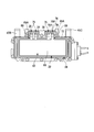
- FIG. 3 is a schematic cross-sectional view of the heat medium heating device shown in FIG. 2 in the A 1 -A 2 line direction.
- FIG. 3 is a schematic cross-sectional view of the heat medium heating device shown in FIG. 2 in the B 1 -B 2 line direction.
- FIG. 3 is a schematic cross-sectional view in the C 1 -C 2 line direction of the heat medium heating device shown in FIG. 2; It is a top view which shows typically the PTC heater screwed to the control board shown in FIG.
- FIG. 3 is a schematic cross-sectional view of the heat medium heating device shown in FIG. 2 in the D 1 -D 2 line direction.
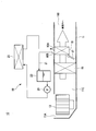
- a vehicle air conditioner 10 according to the present embodiment will be described with reference to FIG. Arrows shown in FIG. 1 indicate the flow direction of air outside or in the vehicle compartment.
- the vehicle air conditioner 10 is an air conditioner applicable to, for example, a hybrid vehicle or an electric vehicle.
- a vehicle air conditioner 10 includes a housing 11, a blower 13, a cooler 15, a radiator 16 that constitutes a heat medium circulation circuit 19, an air mix damper 17, and a heat medium heating device. And 25 a heat medium circulation circuit 19.
- the housing 11 is taken as an inlet 11A, an outlet 11B, and a channel 11C.
- the intake port 11A is an opening for introducing external air or air in the vehicle compartment (hereinafter, simply referred to as "air") into the flow passage 11C.
- the outlet 11B is connected to a plurality of outlets provided in the vehicle compartment for the air that has passed through the flow path 11C.
- the flow path 11C is a path through which the air flows, and is partitioned in the housing 11.
- the blower 13 is provided near the inlet 11A in the housing 11.
- the blower 13 sucks in air from the inlet 11A and pumps the sucked air to the downstream side of the blower 13.
- the cooler 15 is provided in a housing 11 located downstream of the blower 13.
- the cooler 15 is disposed so as to block a part of the flow path 11C.
- the cooler 15 constitutes a refrigerant circuit together with a compressor, a condenser, and an expansion valve not shown.
- the cooler 15 cools the air passing through the cooler 15 by evaporating the refrigerant that has been adiabatically expanded by the expansion valve, and supplies the cooled air to the downstream side of the cooler 15.
- the radiator 16 constitutes a heat medium circulation circuit 19 together with the circulation line 21, the tank 23, the pump 24, the engine (not shown), and the heat medium heating device 25.
- the radiator 16 is provided in the flow passage 11C located downstream of the cooler 15.
- the radiator 16 has an inlet 16A and an outlet 16B connected to the circulation line 21.
- the heat medium is introduced into the inlet 16A via the heat medium heater 25 by the circulation line 21.
- the heat medium having passed through the inside of the radiator 16 is led out to the circulation line 21 from the outlet 16B.
- the radiator 16 heats the air by heat exchange between the air cooled by the cooler 15 and the heat medium, and supplies the heated air to the downstream side.
- the air mix damper 17 is provided in the flow path 11C located between the cooler 15 and the radiator 16.
- the air mix damper 17 is a damper for adjusting the ratio between the amount of air that has passed through the radiator 16 and the amount of air that bypasses the radiator 16 and flows.
- the air mix damper 17 has a function of adjusting the temperature of air mixed downstream of the air mix damper 17.
- the heat medium circulation circuit 19 includes a radiator 16, a circulation line 21, a tank 23, a pump 24, an engine (not shown), and a heat medium heating device 25.
- the heat medium circulation circuit 19 heats the engine coolant by the heat medium heating device 10 when the temperature of the engine coolant, which is a heat medium, does not rise so much, for example, during hybrid operation. Then, by circulating the heated engine cooling water through the circulation line 21 by the pump 24, the air passing through the radiator 16 in the housing 11 is heated.
- the circulation line 21 is disposed outside the housing 11.
- the circulation line 21 connects the radiator 16, the tank 23, the pump 24, the engine (not shown), and the heating medium heating device 25.
- the circulation line 21 is a line for circulating the heat medium.
- the vehicle air conditioner 10 When the vehicle air conditioner 10 is applied to a hybrid vehicle, for example, engine cooling water of the hybrid vehicle can be used as the heat medium. Moreover, when applying the vehicle air conditioner 10 to the electric vehicle which does not have an engine, it is possible to use a brine etc. as said heat medium, for example.
- the tank 23 is provided in the circulation line 21 located on the outlet 16B side. A heat medium is stored in the tank 23.
- the pump 24 is provided in the circulation line 21 located downstream of the tank 23.
- the pump 24 supplies the heat medium in the tank 23 to the heat medium heater 25.
- the heat medium heating device 25 is provided in a circulation line 21 located between the pump 24 and the radiator 16.
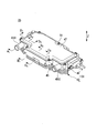
- the configuration of the heat medium heating device 25 will be described with reference to FIGS. 2 to 8.
- the Z direction shown in FIGS. 2 to 5 indicates the stacking direction of the PTC heater 32 and the control board 37.
- the same components are denoted by the same reference numerals.
- Arrows shown in FIG. 4 indicate a state in which the heat medium branches into two and flows.
- FIG. 7 the state which removed the 2nd casing part 42 from the 1st casing part 41 is shown.
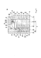
- FIG. 8 only the lower part of the heat medium heating device is shown in a cross-sectional view.
- the heat medium heating device 25 has a casing 31, a PTC heater 32, an insulating member 34, a control board 37, a first screw 38 and a second screw 39.
- the casing 31 has a first casing portion 41 and a second casing portion 42.
- the first casing portion 41 and the second casing portion 42 are configured to be separable (removable from one to the other).
- the first casing portion 41 is disposed on the first surface 61 a side of the PTC element 61 constituting the PTC heater 32.
- the first casing portion 41 is fixed to the second casing portion 42 by a screw or the like.
- the first casing portion 41 has a substrate accommodation portion 45, a flow path forming portion 46, and a lid portion 47.
- the substrate accommodating portion 45 is provided between the flow path forming portion 46 and the lid portion 47.
- the substrate housing portion 45 has a substrate housing recess 45A, a heat medium inlet 45B, and a heat medium outlet 45C.
- the substrate accommodation recess 45 ⁇ / b> A is a recess for accommodating the control substrate 37.
- the heat medium inlet 45B is connected to a circulation line 21 that circulates the heat medium.
- the heat medium inlet 45 ⁇ / b> B introduces the heat medium to the first and second heat medium channels 48, 56 formed in the casing 31.
- the heat medium outlet 45C is connected to the circulation line 21.
- the heat medium outlet 45 ⁇ / b> C causes the heat medium that has passed through the first and second heat medium channels 48 and 56 provided in the casing 31 to be led out to the circulation line 21.
- the flow path forming unit 46 is a plate-like member, and has a plurality of fins 46 ⁇ / b> A in a portion facing the substrate accommodation unit 45.
- the plurality of fins 46A protrude in the direction toward the substrate accommodation portion 45.
- a first heat medium channel 48 is defined between the flow channel forming portion 46 and the substrate housing portion 45.
- the first heat medium channel 48 is a plurality of parallel channels.
- the first heat medium channel 48 communicates with the heat medium inlet 45B and the heat medium outlet 45C.
- the first heat medium channel 48 is disposed to face one surface of the PTC heater 32.
- the lid portion 47 is configured to be separable from the substrate housing portion 45.
- the lid 47 is fixed by a screw 51.
- the lid 47 faces the control substrate 37.
- the second casing portion 42 is disposed on the second surface 61 b side of the PTC element 61.
- the second casing portion 42 has a flow path forming portion 53 and a lid portion 54.
- the flow path forming portion 53 is a plate-like member, and is provided between the flow path forming portion 46 and the lid portion 54.
- the flow path forming portion 53 has a plurality of fins 53A in a portion facing the lid portion 54. The plurality of fins 53A project in the direction toward the lid 54.
- a second heat medium channel 56 is partitioned between the plurality of fins 53A and the lid 54.
- the second heat medium channel 56 is a plurality of parallel flow channels, and is in communication with the heat medium inlet 45B and the heat medium outlet 45C.
- the second heat medium channel 56 is disposed to face the other surface of the PTC heater 32.
- a compressible sheet (not shown in FIGS. 3 to 7), and the insulating member 34 (not shown in FIGS. 4 and 5).
- Space 57 is formed to accommodate the As shown in FIG. 8, both sides of the PTC heater 32 are covered with a compressible heat transfer sheet 64 made of a silicon sheet or the like.
- an insulating member 34 is provided at the periphery of the PTC heater 32.
- the PTC heater 32 is disposed in the space 57.
- the PTC heater 32 has a PTC element 61, a first electrode plate 62, and a second electrode plate 63.
- the PTC element 61 is a rectangular plate-like element, and is disposed between the first electrode plate 62 and the second electrode plate 63.
- the PTC element 61 has a first surface 61 a and a second surface 61 b.
- the first surface 61 a faces the first heat medium channel 48 provided in the first casing portion 41 in the Z direction.
- the second surface 61 b is a surface disposed on the opposite side of the first surface 61 a.
- the second surface 61 b faces the second heat medium channel 56 provided in the second casing portion 42 in the Z direction.
- the first electrode plate 62 has a first electrode body 65 divided into three and three first terminals 66.
- the first electrode main body 65 is a rectangular plate-like electrode.
- the first electrode main body 65 is provided on the first surface 61 a of the PTC element 61.
- the first terminals 66 are respectively provided for the first electrode body 65 divided into three. Of the three first terminals 66, two terminals are arranged adjacent to each other, and the remaining one terminal is provided at a distance from the other two terminals.
- the three first terminals 66 extend from the end of the first electrode body 65 to the outside of the PTC element 61 and in the direction toward the control substrate 37.
- the three first terminals 66 are formed by bending a plate at two points.
- the three first terminals 66 each have a tip 66A in which a through hole 66B is formed, and bent portions 66C and 66D.
- the through hole 66B is a hole into which the shaft portion 38B of the first screw 38 is inserted.
- the front end portion 66A is a portion in contact with the first connection portion 83 constituting the control board 37.
- the three first terminals 66 have the two bent portions 66C and 66D, respectively, so that the tips 66A of the three first terminals 66 and the control board 37 (specifically, in the Z direction) It becomes possible to oppose arrangement
- three first terminals 66 are formed using a tool from the stacking direction (Z direction) of the PTC heater 32 and the control board 37. Can be screwed to the first connection portion 83 of the control board 37.
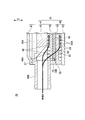
- the second electrode plate 63 has a second electrode body 68 and a second terminal 69.
- the second electrode main body 68 is a rectangular plate-like electrode.
- the second electrode main body 68 is provided on the second surface 61 b of the PTC element 61.
- one second terminal 69 is provided on the long side located on the side where the first terminal 66 is provided.
- the second terminal 69 is disposed adjacent to one first terminal 66 provided at a position separated from the two first terminals 66 among the three first terminals 66.
- the second terminal 69 extends from the end of the second electrode body 68 to the outside of the PTC element 61 and in the direction toward the control substrate 37.
- the second terminal 69 has a shape in which a plate material is bent at two points.
- the second terminal 69 has a tip end portion 69A in which the through hole 69B is formed, and bent portions 69C and 69D.
- the through hole 69B is a hole into which the shaft portion 38B of the first screw 38 is inserted.
- the tip end portion 69A is a portion in contact with the second connection portion 84 constituting the control substrate 37.
- the bent portion 69 ⁇ / b> C is disposed in the vicinity of the PTC element 61.
- the bent portion 69C is a portion bent in order to make the extension direction of the second terminal 69 a direction (Z direction) toward the control board 37.
- the bent portion 69D is disposed in the vicinity of the tip end portion 69A.
- the bent portion 69D is a portion bent in order to make the extending direction of the tip portion 69A orthogonal to the Z direction.
- the second terminal 69 having the two bent portions 69C and 69D allows the tip 69A of the second terminal 69 and the control board 37 (specifically, the second terminal 69 to be described later) in the Z direction. It becomes possible to face the connection portion 84).
- the tip of the second terminal 69 is formed using a tool from the stacking direction (Z direction) of the PTC heater 32 and the control board 37.
- the portion 69A can be screwed to the second connection portion 84 of the control board 37.
- the PTC heater 32 configured as described above heats the heat medium flowing through the first and second heat medium channels 48 and 56.
- the heat medium heated by the PTC heater 32 is introduced into the radiator 16 through the inlet 16 A of the radiator 16.
- An insulating plate (not shown) is provided between the PTC heater 32 and the flow path forming portions 46 and 53.
- the PTC heater 32 and the flow path forming portions 46 and 53 are insulated by the insulating plate.
- first and second terminals 66 and 69 are illustrated in FIG. 3 as an example, the first and second terminals 66 and 69 are illustrated.
- the number of is not limited to the number of divisions described in the present embodiment.
- FIG. 3 the case where the first and second terminals 66 and 69 respectively have two bent portions (folded portions 66C and 66D or bent portions 69C and 69D) is taken as an example.
- the number of bent portions of the first and second terminals 66 and 69 may be two or more, and is not limited to two.
- the insulating member 34 has a frame 73, a first guide portion 75, and a second guide portion 76.
- the frame 73 is shaped so as to surround the side surface of a structure including the first electrode main body 65, the PTC element 61, and the second electrode main body 68.
- the frame 73 is disposed between the flow passage forming portion 46 and the flow passage forming portion 53 in a state of surrounding the side surface of the structure including the first electrode main body 65, the PTC element 61, and the second electrode main body 68. It is done.
- the outer peripheral surface of the frame 73 is in contact with the inner surface of the casing 31.
- first guide portions 75 are provided on the long side of the frame 73.
- the two first guide portions 75 are provided adjacent to each other.
- the remaining one first guide portion 75 is provided at a distance from the other two first guide portions 75.
- the first guide portion 75 has a first opening 75A into which the first terminal 66 is inserted and which extends in the Z direction.
- the first guide portion 75 is shaped to surround the first terminal 66.
- One second guide portion 76 is provided on the long side of the frame 73 provided with the first guide portion 75.
- the second guide portion 76 is disposed adjacent to one first guide portion 75.
- the second guide portion 76 has a second opening 76A into which the second terminal 69 is inserted and which extends in the Z direction.
- the first guide portion 75 is shaped to surround the first terminal 66.
- the insulating member 34 configured as described above, it is possible to insulate between the conductor disposed around the side surface of the PTC heater 32 and the side surface of the PTC heater 32, and to connect the PTC heater 32 to the control substrate 37. Positioning can be performed.
- the control substrate 37 includes a substrate main body 81, a first connection portion 83, a second connection portion 84, and an electronic component 85.
- the substrate body 81 is configured such that a circuit pattern (a control circuit pattern, a power supply circuit pattern, and the like) is formed on the surface of the plate-like substrate.
- the substrate main body 81 is fixed on the substrate accommodation portion 45 by screws or bolts.
- the substrate main body 81 has a surface 81 a facing the substrate accommodation portion 45.
- the first connection portion 83 is a terminal block, and three first connection portions 83 are provided on the outer peripheral portion of the surface 81 a of the substrate main body 81.
- the first connection portion 83 is disposed at a position facing the tip portion 66A of the first terminal 66.
- the first connection portion 83 protrudes in the Z direction from the surface 81 a of the substrate main body 81 toward the second casing portion 42.
- the first connection portion 83 is electrically connected to the substrate body 81.
- the first connection portion 83 is provided with a screw hole 83A facing the through hole 66B.
- the second connection portion 84 is a terminal block, and one second connection portion 84 is provided on the outer peripheral portion of the surface 81 a of the substrate main body 81.
- the second connection portion 84 is disposed at a position facing the tip portion 69A of the second terminal 69.
- the second connection portion 84 protrudes in the Z direction from the surface 81 a of the substrate main body 81 toward the second casing portion 42.
- the second connection portion 84 is electrically connected to the substrate body 81.
- the second connection portion 84 is provided with a screw hole 84A opposite to the through hole 69B.
- the electronic component 85 is mounted on the substrate body 81.
- the electronic component 85 is electrically connected to the substrate body 81.
- an electronic component having heat generating property such as IGBT (Insulated Gate Bipolar Transistor: Insulated Gate Type Bipolar Transistor) or FET (Field Effect Transistor: Field Effect Transistor), and electronic components other than these are used. It is possible.
- the second screw 39 has a head 39A and a shaft 39B.
- the second screw 39 is screwed into the screw hole 84A of the second connection portion 84 in a state in which the shaft portion 39B is inserted into the through hole 69B.
- the tip end portion 69A of the second terminal 69 is fixed to the second connection portion 84 by the second screw 39 and is electrically connected to the control board 37.
- the head portion 39A is disposed on the second casing portion 42 side.
- the head portion 39A is exposed from the first casing portion 41 by removing the second casing portion 42 from the first casing portion 41.
- the second screw 39 is screwed from the Z direction with the second casing portion 42 removed from the first casing portion 41.
- first and second screws 38 and 39 can be checked while confirming the positional relationship between the first and second connection portions 83 and 84 and the first and second terminals 66 and 69. Can be screwed together.
Landscapes
- Engineering & Computer Science (AREA)
- Physics & Mathematics (AREA)
- Thermal Sciences (AREA)
- Mechanical Engineering (AREA)
- Chemical & Material Sciences (AREA)
- Combustion & Propulsion (AREA)
- General Engineering & Computer Science (AREA)
- Air-Conditioning For Vehicles (AREA)
- Resistance Heating (AREA)
Priority Applications (3)
| Application Number | Priority Date | Filing Date | Title |
|---|---|---|---|
| US16/482,573 US20200039324A1 (en) | 2017-02-17 | 2018-01-18 | Heat medium heating device, and vehicular air conditioning device |
| DE112018000888.6T DE112018000888T5 (de) | 2017-02-17 | 2018-01-18 | Wärmemedium-heizvorrichtung und fahrzeug-klimatisierungsvorrichtung |
| CN201880009505.0A CN110291842B (zh) | 2017-02-17 | 2018-01-18 | 热介质加热装置和车用空调装置 |
Applications Claiming Priority (2)
| Application Number | Priority Date | Filing Date | Title |
|---|---|---|---|
| JP2017-027930 | 2017-02-17 | ||
| JP2017027930A JP6803258B2 (ja) | 2017-02-17 | 2017-02-17 | 熱媒体加熱装置、及び車両用空調装置 |
Publications (1)
| Publication Number | Publication Date |
|---|---|
| WO2018150795A1 true WO2018150795A1 (ja) | 2018-08-23 |
Family
ID=63170639
Family Applications (1)
| Application Number | Title | Priority Date | Filing Date |
|---|---|---|---|
| PCT/JP2018/001363 Ceased WO2018150795A1 (ja) | 2017-02-17 | 2018-01-18 | 熱媒体加熱装置、及び車両用空調装置 |
Country Status (5)
| Country | Link |
|---|---|
| US (1) | US20200039324A1 (enExample) |
| JP (1) | JP6803258B2 (enExample) |
| CN (1) | CN110291842B (enExample) |
| DE (1) | DE112018000888T5 (enExample) |
| WO (1) | WO2018150795A1 (enExample) |
Families Citing this family (11)
| Publication number | Priority date | Publication date | Assignee | Title |
|---|---|---|---|---|
| KR102484607B1 (ko) * | 2018-05-28 | 2023-01-06 | 한온시스템 주식회사 | 냉각수 히터 |
| US10806022B2 (en) * | 2018-08-09 | 2020-10-13 | Hanon Systems | Fluid heating heater |
| JP7126411B2 (ja) * | 2018-09-11 | 2022-08-26 | 三菱重工サーマルシステムズ株式会社 | 熱媒体加熱装置及び車両用空調装置 |
| JP2020044865A (ja) * | 2018-09-14 | 2020-03-26 | 三菱重工サーマルシステムズ株式会社 | 熱媒体加熱装置及び車両用空調装置 |
| JP2020053241A (ja) * | 2018-09-26 | 2020-04-02 | 三菱重工サーマルシステムズ株式会社 | 熱媒体加熱装置及び車両用空調装置 |
| EP3722124B1 (en) * | 2019-04-08 | 2023-12-13 | Borgwarner Emissions Systems Spain, S.L.U. | Heating device for use thereof in a vehicle |
| US11758692B2 (en) * | 2020-06-12 | 2023-09-12 | Auras Technology Co., Ltd. | Heat dissipation module |
| DE102021103483A1 (de) * | 2021-02-15 | 2022-08-18 | Bayerische Motoren Werke Aktiengesellschaft | Klimasystem für ein elektrisch antreibbares Kraftfahrzeug mit einem Kühlkörper und einer Heizeinrichtung, Kraftfahrzeug sowie Verfahren zum Betreiben eines Klimasystems |
| DE102022110017A1 (de) * | 2021-06-18 | 2022-12-22 | Borgwarner Ludwigsburg Gmbh | Durchlauferhitzer für Automobile |
| KR20230146852A (ko) * | 2022-04-13 | 2023-10-20 | 한온시스템 주식회사 | 차량용 난방장치 |
| JP2025036835A (ja) | 2023-09-05 | 2025-03-17 | 日本特殊陶業株式会社 | 加熱装置 |
Citations (3)
| Publication number | Priority date | Publication date | Assignee | Title |
|---|---|---|---|---|
| JPS6183291U (enExample) * | 1984-11-07 | 1986-06-02 | ||
| JPH1086851A (ja) * | 1996-09-19 | 1998-04-07 | Sekisui Plastics Co Ltd | 車両用凍結防止装置 |
| JP2013220706A (ja) * | 2012-04-16 | 2013-10-28 | Mitsubishi Heavy Ind Ltd | 熱媒体加熱装置およびそれを備えた車両用空調装置 |
Family Cites Families (9)
| Publication number | Priority date | Publication date | Assignee | Title |
|---|---|---|---|---|
| ES2349351T3 (es) * | 2007-07-20 | 2010-12-30 | EBERSPÄCHER CATEM GMBH & CO. KG | Dispositivo eléctrico de calefacción en especial para vehículos a motor. |
| JP2011016489A (ja) * | 2009-07-10 | 2011-01-27 | Mitsubishi Heavy Ind Ltd | 熱媒体加熱装置およびそれを用いた車両用空調装置 |
| JP2012196985A (ja) * | 2011-03-18 | 2012-10-18 | Mitsubishi Heavy Ind Ltd | 熱媒体加熱装置およびそれを備えた車両用空調装置 |
| JP2012218557A (ja) * | 2011-04-07 | 2012-11-12 | Mitsubishi Heavy Ind Ltd | 熱媒体加熱装置およびそれを備えた車両用空調装置 |
| EP2608631B1 (de) * | 2011-12-22 | 2016-09-14 | Eberspächer catem GmbH & Co. KG | Wärme erzeugendes Element |
| JP2017027930A (ja) | 2015-07-24 | 2017-02-02 | 三井化学株式会社 | 電池用非水電解液及びリチウム二次電池 |
| CN205641499U (zh) * | 2016-04-22 | 2016-10-12 | 比亚迪股份有限公司 | 加热器、暖风系统及汽车 |
| CN205632035U (zh) * | 2016-04-22 | 2016-10-12 | 比亚迪股份有限公司 | 加热器、暖风系统及汽车 |
| CN106211373B (zh) * | 2016-08-22 | 2023-07-28 | 威海市科博乐汽车电子有限公司 | 一种ptc加热器 |
-
2017
- 2017-02-17 JP JP2017027930A patent/JP6803258B2/ja not_active Expired - Fee Related
-
2018
- 2018-01-18 WO PCT/JP2018/001363 patent/WO2018150795A1/ja not_active Ceased
- 2018-01-18 CN CN201880009505.0A patent/CN110291842B/zh not_active Expired - Fee Related
- 2018-01-18 US US16/482,573 patent/US20200039324A1/en not_active Abandoned
- 2018-01-18 DE DE112018000888.6T patent/DE112018000888T5/de not_active Withdrawn
Patent Citations (3)
| Publication number | Priority date | Publication date | Assignee | Title |
|---|---|---|---|---|
| JPS6183291U (enExample) * | 1984-11-07 | 1986-06-02 | ||
| JPH1086851A (ja) * | 1996-09-19 | 1998-04-07 | Sekisui Plastics Co Ltd | 車両用凍結防止装置 |
| JP2013220706A (ja) * | 2012-04-16 | 2013-10-28 | Mitsubishi Heavy Ind Ltd | 熱媒体加熱装置およびそれを備えた車両用空調装置 |
Also Published As
| Publication number | Publication date |
|---|---|
| CN110291842B (zh) | 2021-09-03 |
| CN110291842A (zh) | 2019-09-27 |
| JP2018133300A (ja) | 2018-08-23 |
| US20200039324A1 (en) | 2020-02-06 |
| JP6803258B2 (ja) | 2020-12-23 |
| DE112018000888T5 (de) | 2019-10-24 |
Similar Documents
| Publication | Publication Date | Title |
|---|---|---|
| WO2018150795A1 (ja) | 熱媒体加熱装置、及び車両用空調装置 | |
| EP2559573B1 (en) | Heat medium heating device and vehicle air conditioning apparatus using the same | |
| US8948582B2 (en) | Heat medium heating device and vehicle air conditioner including the same | |
| KR101647912B1 (ko) | 자동차용 유체를 전기적으로 가열하는 장치 및 관련된 가열 및/또는 공기조화 장치 | |
| US9186956B2 (en) | Heat medium heating unit and vehicle air conditioning apparatus provided with the same | |
| US12384225B2 (en) | Power supply module for heating radiator and heating radiator fitted with such a module | |
| US20080205001A1 (en) | Blower and air conditioner for vehicle | |
| JP6803259B2 (ja) | 熱媒体加熱装置、及び車両用空調装置 | |
| JP2012017031A (ja) | 熱媒体加熱装置およびそれを用いた車両用空気調和装置 | |
| CN111836734B (zh) | 鼓风机控制模块以及相应的供暖和/或通风和/或空调装置 | |
| JP2013220707A (ja) | 熱媒体加熱装置およびそれを備えた車両用空調装置 | |
| JP2004217023A (ja) | 補助ヒータにおける半導体素子の取付け構造 | |
| JP7743339B2 (ja) | 熱媒体加熱装置 | |
| JP2020053241A (ja) | 熱媒体加熱装置及び車両用空調装置 | |
| WO2020036017A1 (ja) | 熱媒体加熱装置及び車両用空調装置 | |
| WO2023112053A1 (en) | A high voltage fluid heater (hvch) | |
| CN120456493A (zh) | 车载设备的冷却构造 | |
| WO2023181723A1 (ja) | 熱媒体加熱装置 | |
| WO2020066265A1 (ja) | 熱媒体加熱装置及び車両用空調装置 |
Legal Events
| Date | Code | Title | Description |
|---|---|---|---|
| 121 | Ep: the epo has been informed by wipo that ep was designated in this application |
Ref document number: 18754356 Country of ref document: EP Kind code of ref document: A1 |
|
| 122 | Ep: pct application non-entry in european phase |
Ref document number: 18754356 Country of ref document: EP Kind code of ref document: A1 |