WO2018150795A1 - Heat medium heating device, and vehicular air conditioner - Google Patents
Heat medium heating device, and vehicular air conditioner Download PDFInfo
- Publication number
- WO2018150795A1 WO2018150795A1 PCT/JP2018/001363 JP2018001363W WO2018150795A1 WO 2018150795 A1 WO2018150795 A1 WO 2018150795A1 JP 2018001363 W JP2018001363 W JP 2018001363W WO 2018150795 A1 WO2018150795 A1 WO 2018150795A1
- Authority
- WO
- WIPO (PCT)
- Prior art keywords
- heat medium
- terminal
- casing
- heating device
- ptc heater
- Prior art date
Links
Images


Classifications
-
- H—ELECTRICITY
- H05—ELECTRIC TECHNIQUES NOT OTHERWISE PROVIDED FOR
- H05B—ELECTRIC HEATING; ELECTRIC LIGHT SOURCES NOT OTHERWISE PROVIDED FOR; CIRCUIT ARRANGEMENTS FOR ELECTRIC LIGHT SOURCES, IN GENERAL
- H05B3/00—Ohmic-resistance heating
- H05B3/20—Heating elements having extended surface area substantially in a two-dimensional plane, e.g. plate-heater
- H05B3/22—Heating elements having extended surface area substantially in a two-dimensional plane, e.g. plate-heater non-flexible
- H05B3/24—Heating elements having extended surface area substantially in a two-dimensional plane, e.g. plate-heater non-flexible heating conductor being self-supporting
-
- B—PERFORMING OPERATIONS; TRANSPORTING
- B60—VEHICLES IN GENERAL
- B60H—ARRANGEMENTS OF HEATING, COOLING, VENTILATING OR OTHER AIR-TREATING DEVICES SPECIALLY ADAPTED FOR PASSENGER OR GOODS SPACES OF VEHICLES
- B60H1/00—Heating, cooling or ventilating [HVAC] devices
- B60H1/22—Heating, cooling or ventilating [HVAC] devices the heat being derived otherwise than from the propulsion plant
- B60H1/2215—Heating, cooling or ventilating [HVAC] devices the heat being derived otherwise than from the propulsion plant the heat being derived from electric heaters
- B60H1/2218—Heating, cooling or ventilating [HVAC] devices the heat being derived otherwise than from the propulsion plant the heat being derived from electric heaters controlling the operation of electric heaters
-
- B—PERFORMING OPERATIONS; TRANSPORTING
- B60—VEHICLES IN GENERAL
- B60H—ARRANGEMENTS OF HEATING, COOLING, VENTILATING OR OTHER AIR-TREATING DEVICES SPECIALLY ADAPTED FOR PASSENGER OR GOODS SPACES OF VEHICLES
- B60H1/00—Heating, cooling or ventilating [HVAC] devices
- B60H1/22—Heating, cooling or ventilating [HVAC] devices the heat being derived otherwise than from the propulsion plant
- B60H1/2215—Heating, cooling or ventilating [HVAC] devices the heat being derived otherwise than from the propulsion plant the heat being derived from electric heaters
- B60H1/2221—Heating, cooling or ventilating [HVAC] devices the heat being derived otherwise than from the propulsion plant the heat being derived from electric heaters arrangements of electric heaters for heating an intermediate liquid
-
- B—PERFORMING OPERATIONS; TRANSPORTING
- B60—VEHICLES IN GENERAL
- B60H—ARRANGEMENTS OF HEATING, COOLING, VENTILATING OR OTHER AIR-TREATING DEVICES SPECIALLY ADAPTED FOR PASSENGER OR GOODS SPACES OF VEHICLES
- B60H1/00—Heating, cooling or ventilating [HVAC] devices
- B60H1/22—Heating, cooling or ventilating [HVAC] devices the heat being derived otherwise than from the propulsion plant
- B60H1/2215—Heating, cooling or ventilating [HVAC] devices the heat being derived otherwise than from the propulsion plant the heat being derived from electric heaters
- B60H1/2225—Heating, cooling or ventilating [HVAC] devices the heat being derived otherwise than from the propulsion plant the heat being derived from electric heaters arrangements of electric heaters for heating air
-
- F—MECHANICAL ENGINEERING; LIGHTING; HEATING; WEAPONS; BLASTING
- F24—HEATING; RANGES; VENTILATING
- F24H—FLUID HEATERS, e.g. WATER OR AIR HEATERS, HAVING HEAT-GENERATING MEANS, e.g. HEAT PUMPS, IN GENERAL
- F24H1/00—Water heaters, e.g. boilers, continuous-flow heaters or water-storage heaters
- F24H1/10—Continuous-flow heaters, i.e. heaters in which heat is generated only while the water is flowing, e.g. with direct contact of the water with the heating medium
-
- H—ELECTRICITY
- H05—ELECTRIC TECHNIQUES NOT OTHERWISE PROVIDED FOR
- H05B—ELECTRIC HEATING; ELECTRIC LIGHT SOURCES NOT OTHERWISE PROVIDED FOR; CIRCUIT ARRANGEMENTS FOR ELECTRIC LIGHT SOURCES, IN GENERAL
- H05B1/00—Details of electric heating devices
- H05B1/02—Automatic switching arrangements specially adapted to apparatus ; Control of heating devices
- H05B1/0227—Applications
- H05B1/023—Industrial applications
- H05B1/0236—Industrial applications for vehicles
-
- H—ELECTRICITY
- H05—ELECTRIC TECHNIQUES NOT OTHERWISE PROVIDED FOR
- H05B—ELECTRIC HEATING; ELECTRIC LIGHT SOURCES NOT OTHERWISE PROVIDED FOR; CIRCUIT ARRANGEMENTS FOR ELECTRIC LIGHT SOURCES, IN GENERAL
- H05B2203/00—Aspects relating to Ohmic resistive heating covered by group H05B3/00
- H05B2203/02—Heaters using heating elements having a positive temperature coefficient
-
- H—ELECTRICITY
- H05—ELECTRIC TECHNIQUES NOT OTHERWISE PROVIDED FOR
- H05B—ELECTRIC HEATING; ELECTRIC LIGHT SOURCES NOT OTHERWISE PROVIDED FOR; CIRCUIT ARRANGEMENTS FOR ELECTRIC LIGHT SOURCES, IN GENERAL
- H05B2203/00—Aspects relating to Ohmic resistive heating covered by group H05B3/00
- H05B2203/022—Heaters specially adapted for heating gaseous material
- H05B2203/023—Heaters of the type used for electrically heating the air blown in a vehicle compartment by the vehicle heating system
Definitions
- the present invention relates to a heat medium heating device and a vehicle air conditioner provided with the heat medium heating device.
- Priority is claimed on Japanese Patent Application No. 2017-027930, filed Feb. 17, 2017, the content of which is incorporated herein by reference.
- Patent Document 1 discloses a heat medium heating device having a PTC heater, a control substrate, and a casing that accommodates the PTC heater and the control substrate in a stacked state.
- the PCT heater includes a PTC element, and a terminal extending in the stacking direction of the PTC heater and the control substrate, and has a pair of electrode plates provided on both sides of the PTC element.
- the control board is electrically connected to the pair of electrode plates by screwing the terminals of the pair of electrode plates. The control board controls energization of the PTC heater.
- an object of the present invention is to provide a heat medium heating device capable of enhancing work efficiency when screwing a terminal of an electrode plate to a control substrate, and a vehicle air conditioner.
- a second screw for fixing the front end of the second terminal to the second connection, and the front end of the first terminal and the first connection in the stacking direction of the PTC heater and the control board A state in which the second casing portion is removed from the first casing portion by arranging the tip of the second terminal and the second connection portion in the stacking direction of the PTC heater and the control board while facing each other.
- the first and second screws can be screwed together in the stacking direction of the PTC heater and the control board.
- the first and second terminals may have at least two bent portions.
- the tip end portion of the first terminal and the first connection portion are disposed to face each other in the stacking direction of the PTC heater and the control substrate.
- the tip of the second terminal and the second connection portion can be disposed opposite to each other in the stacking direction of the PTC heater and the control board.
- the insulating member configured in this way, it is possible to insulate between the conductor disposed around the side surface of the PTC heater and the side surface of the PTC heater, and to position the PTC heater with respect to the control substrate be able to.
- first and second guide portions configured in this way, it is possible to insulate between the conductors arranged around the first and second terminals and the first and second terminals. it can.
- the heat medium introduced into the casing may branch and flow through the first and second heat medium flow paths.
- a vehicle air conditioner includes the heat medium heating device, a blower for circulating outside air or air in a vehicle compartment, and a cooling device provided downstream of the blower for cooling the outside air or the air. And a radiator which is provided downstream of the cooler and through which the heat medium heated by the PTC heater is circulated.
- the vehicle air conditioner includes the heat medium heating device, so that the work efficiency when screwing the first and second terminals to the control board can be enhanced.
- the working efficiency when screwing the terminal of the electrode plate to the control substrate can be enhanced.
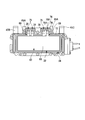
- FIG. 3 is a schematic cross-sectional view of the heat medium heating device shown in FIG. 2 in the A 1 -A 2 line direction.
- FIG. 3 is a schematic cross-sectional view of the heat medium heating device shown in FIG. 2 in the B 1 -B 2 line direction.
- FIG. 3 is a schematic cross-sectional view in the C 1 -C 2 line direction of the heat medium heating device shown in FIG. 2; It is a top view which shows typically the PTC heater screwed to the control board shown in FIG.
- FIG. 3 is a schematic cross-sectional view of the heat medium heating device shown in FIG. 2 in the D 1 -D 2 line direction.
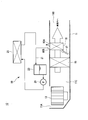
- a vehicle air conditioner 10 according to the present embodiment will be described with reference to FIG. Arrows shown in FIG. 1 indicate the flow direction of air outside or in the vehicle compartment.
- the vehicle air conditioner 10 is an air conditioner applicable to, for example, a hybrid vehicle or an electric vehicle.
- a vehicle air conditioner 10 includes a housing 11, a blower 13, a cooler 15, a radiator 16 that constitutes a heat medium circulation circuit 19, an air mix damper 17, and a heat medium heating device. And 25 a heat medium circulation circuit 19.
- the housing 11 is taken as an inlet 11A, an outlet 11B, and a channel 11C.
- the intake port 11A is an opening for introducing external air or air in the vehicle compartment (hereinafter, simply referred to as "air") into the flow passage 11C.
- the outlet 11B is connected to a plurality of outlets provided in the vehicle compartment for the air that has passed through the flow path 11C.
- the flow path 11C is a path through which the air flows, and is partitioned in the housing 11.
- the blower 13 is provided near the inlet 11A in the housing 11.
- the blower 13 sucks in air from the inlet 11A and pumps the sucked air to the downstream side of the blower 13.
- the cooler 15 is provided in a housing 11 located downstream of the blower 13.
- the cooler 15 is disposed so as to block a part of the flow path 11C.
- the cooler 15 constitutes a refrigerant circuit together with a compressor, a condenser, and an expansion valve not shown.
- the cooler 15 cools the air passing through the cooler 15 by evaporating the refrigerant that has been adiabatically expanded by the expansion valve, and supplies the cooled air to the downstream side of the cooler 15.
- the radiator 16 constitutes a heat medium circulation circuit 19 together with the circulation line 21, the tank 23, the pump 24, the engine (not shown), and the heat medium heating device 25.
- the radiator 16 is provided in the flow passage 11C located downstream of the cooler 15.
- the radiator 16 has an inlet 16A and an outlet 16B connected to the circulation line 21.
- the heat medium is introduced into the inlet 16A via the heat medium heater 25 by the circulation line 21.
- the heat medium having passed through the inside of the radiator 16 is led out to the circulation line 21 from the outlet 16B.
- the radiator 16 heats the air by heat exchange between the air cooled by the cooler 15 and the heat medium, and supplies the heated air to the downstream side.
- the air mix damper 17 is provided in the flow path 11C located between the cooler 15 and the radiator 16.
- the air mix damper 17 is a damper for adjusting the ratio between the amount of air that has passed through the radiator 16 and the amount of air that bypasses the radiator 16 and flows.
- the air mix damper 17 has a function of adjusting the temperature of air mixed downstream of the air mix damper 17.
- the heat medium circulation circuit 19 includes a radiator 16, a circulation line 21, a tank 23, a pump 24, an engine (not shown), and a heat medium heating device 25.
- the heat medium circulation circuit 19 heats the engine coolant by the heat medium heating device 10 when the temperature of the engine coolant, which is a heat medium, does not rise so much, for example, during hybrid operation. Then, by circulating the heated engine cooling water through the circulation line 21 by the pump 24, the air passing through the radiator 16 in the housing 11 is heated.
- the circulation line 21 is disposed outside the housing 11.
- the circulation line 21 connects the radiator 16, the tank 23, the pump 24, the engine (not shown), and the heating medium heating device 25.
- the circulation line 21 is a line for circulating the heat medium.
- the vehicle air conditioner 10 When the vehicle air conditioner 10 is applied to a hybrid vehicle, for example, engine cooling water of the hybrid vehicle can be used as the heat medium. Moreover, when applying the vehicle air conditioner 10 to the electric vehicle which does not have an engine, it is possible to use a brine etc. as said heat medium, for example.
- the tank 23 is provided in the circulation line 21 located on the outlet 16B side. A heat medium is stored in the tank 23.
- the pump 24 is provided in the circulation line 21 located downstream of the tank 23.
- the pump 24 supplies the heat medium in the tank 23 to the heat medium heater 25.
- the heat medium heating device 25 is provided in a circulation line 21 located between the pump 24 and the radiator 16.
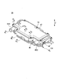
- the configuration of the heat medium heating device 25 will be described with reference to FIGS. 2 to 8.
- the Z direction shown in FIGS. 2 to 5 indicates the stacking direction of the PTC heater 32 and the control board 37.
- the same components are denoted by the same reference numerals.
- Arrows shown in FIG. 4 indicate a state in which the heat medium branches into two and flows.
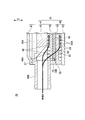
- FIG. 7 the state which removed the 2nd casing part 42 from the 1st casing part 41 is shown.
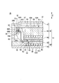
- FIG. 8 only the lower part of the heat medium heating device is shown in a cross-sectional view.
- the heat medium heating device 25 has a casing 31, a PTC heater 32, an insulating member 34, a control board 37, a first screw 38 and a second screw 39.
- the casing 31 has a first casing portion 41 and a second casing portion 42.
- the first casing portion 41 and the second casing portion 42 are configured to be separable (removable from one to the other).
- the first casing portion 41 is disposed on the first surface 61 a side of the PTC element 61 constituting the PTC heater 32.
- the first casing portion 41 is fixed to the second casing portion 42 by a screw or the like.
- the first casing portion 41 has a substrate accommodation portion 45, a flow path forming portion 46, and a lid portion 47.
- the substrate accommodating portion 45 is provided between the flow path forming portion 46 and the lid portion 47.
- the substrate housing portion 45 has a substrate housing recess 45A, a heat medium inlet 45B, and a heat medium outlet 45C.
- the substrate accommodation recess 45 ⁇ / b> A is a recess for accommodating the control substrate 37.
- the heat medium inlet 45B is connected to a circulation line 21 that circulates the heat medium.
- the heat medium inlet 45 ⁇ / b> B introduces the heat medium to the first and second heat medium channels 48, 56 formed in the casing 31.
- the heat medium outlet 45C is connected to the circulation line 21.
- the heat medium outlet 45 ⁇ / b> C causes the heat medium that has passed through the first and second heat medium channels 48 and 56 provided in the casing 31 to be led out to the circulation line 21.
- the flow path forming unit 46 is a plate-like member, and has a plurality of fins 46 ⁇ / b> A in a portion facing the substrate accommodation unit 45.
- the plurality of fins 46A protrude in the direction toward the substrate accommodation portion 45.
- a first heat medium channel 48 is defined between the flow channel forming portion 46 and the substrate housing portion 45.
- the first heat medium channel 48 is a plurality of parallel channels.
- the first heat medium channel 48 communicates with the heat medium inlet 45B and the heat medium outlet 45C.
- the first heat medium channel 48 is disposed to face one surface of the PTC heater 32.
- the lid portion 47 is configured to be separable from the substrate housing portion 45.
- the lid 47 is fixed by a screw 51.
- the lid 47 faces the control substrate 37.
- the second casing portion 42 is disposed on the second surface 61 b side of the PTC element 61.
- the second casing portion 42 has a flow path forming portion 53 and a lid portion 54.
- the flow path forming portion 53 is a plate-like member, and is provided between the flow path forming portion 46 and the lid portion 54.
- the flow path forming portion 53 has a plurality of fins 53A in a portion facing the lid portion 54. The plurality of fins 53A project in the direction toward the lid 54.
- a second heat medium channel 56 is partitioned between the plurality of fins 53A and the lid 54.
- the second heat medium channel 56 is a plurality of parallel flow channels, and is in communication with the heat medium inlet 45B and the heat medium outlet 45C.
- the second heat medium channel 56 is disposed to face the other surface of the PTC heater 32.
- a compressible sheet (not shown in FIGS. 3 to 7), and the insulating member 34 (not shown in FIGS. 4 and 5).
- Space 57 is formed to accommodate the As shown in FIG. 8, both sides of the PTC heater 32 are covered with a compressible heat transfer sheet 64 made of a silicon sheet or the like.
- an insulating member 34 is provided at the periphery of the PTC heater 32.
- the PTC heater 32 is disposed in the space 57.
- the PTC heater 32 has a PTC element 61, a first electrode plate 62, and a second electrode plate 63.
- the PTC element 61 is a rectangular plate-like element, and is disposed between the first electrode plate 62 and the second electrode plate 63.
- the PTC element 61 has a first surface 61 a and a second surface 61 b.
- the first surface 61 a faces the first heat medium channel 48 provided in the first casing portion 41 in the Z direction.
- the second surface 61 b is a surface disposed on the opposite side of the first surface 61 a.
- the second surface 61 b faces the second heat medium channel 56 provided in the second casing portion 42 in the Z direction.
- the first electrode plate 62 has a first electrode body 65 divided into three and three first terminals 66.
- the first electrode main body 65 is a rectangular plate-like electrode.
- the first electrode main body 65 is provided on the first surface 61 a of the PTC element 61.
- the first terminals 66 are respectively provided for the first electrode body 65 divided into three. Of the three first terminals 66, two terminals are arranged adjacent to each other, and the remaining one terminal is provided at a distance from the other two terminals.
- the three first terminals 66 extend from the end of the first electrode body 65 to the outside of the PTC element 61 and in the direction toward the control substrate 37.
- the three first terminals 66 are formed by bending a plate at two points.
- the three first terminals 66 each have a tip 66A in which a through hole 66B is formed, and bent portions 66C and 66D.
- the through hole 66B is a hole into which the shaft portion 38B of the first screw 38 is inserted.
- the front end portion 66A is a portion in contact with the first connection portion 83 constituting the control board 37.
- the three first terminals 66 have the two bent portions 66C and 66D, respectively, so that the tips 66A of the three first terminals 66 and the control board 37 (specifically, in the Z direction) It becomes possible to oppose arrangement
- three first terminals 66 are formed using a tool from the stacking direction (Z direction) of the PTC heater 32 and the control board 37. Can be screwed to the first connection portion 83 of the control board 37.
- the second electrode plate 63 has a second electrode body 68 and a second terminal 69.
- the second electrode main body 68 is a rectangular plate-like electrode.
- the second electrode main body 68 is provided on the second surface 61 b of the PTC element 61.
- one second terminal 69 is provided on the long side located on the side where the first terminal 66 is provided.
- the second terminal 69 is disposed adjacent to one first terminal 66 provided at a position separated from the two first terminals 66 among the three first terminals 66.
- the second terminal 69 extends from the end of the second electrode body 68 to the outside of the PTC element 61 and in the direction toward the control substrate 37.
- the second terminal 69 has a shape in which a plate material is bent at two points.
- the second terminal 69 has a tip end portion 69A in which the through hole 69B is formed, and bent portions 69C and 69D.
- the through hole 69B is a hole into which the shaft portion 38B of the first screw 38 is inserted.
- the tip end portion 69A is a portion in contact with the second connection portion 84 constituting the control substrate 37.
- the bent portion 69 ⁇ / b> C is disposed in the vicinity of the PTC element 61.
- the bent portion 69C is a portion bent in order to make the extension direction of the second terminal 69 a direction (Z direction) toward the control board 37.
- the bent portion 69D is disposed in the vicinity of the tip end portion 69A.
- the bent portion 69D is a portion bent in order to make the extending direction of the tip portion 69A orthogonal to the Z direction.
- the second terminal 69 having the two bent portions 69C and 69D allows the tip 69A of the second terminal 69 and the control board 37 (specifically, the second terminal 69 to be described later) in the Z direction. It becomes possible to face the connection portion 84).
- the tip of the second terminal 69 is formed using a tool from the stacking direction (Z direction) of the PTC heater 32 and the control board 37.
- the portion 69A can be screwed to the second connection portion 84 of the control board 37.
- the PTC heater 32 configured as described above heats the heat medium flowing through the first and second heat medium channels 48 and 56.
- the heat medium heated by the PTC heater 32 is introduced into the radiator 16 through the inlet 16 A of the radiator 16.
- An insulating plate (not shown) is provided between the PTC heater 32 and the flow path forming portions 46 and 53.
- the PTC heater 32 and the flow path forming portions 46 and 53 are insulated by the insulating plate.
- first and second terminals 66 and 69 are illustrated in FIG. 3 as an example, the first and second terminals 66 and 69 are illustrated.
- the number of is not limited to the number of divisions described in the present embodiment.
- FIG. 3 the case where the first and second terminals 66 and 69 respectively have two bent portions (folded portions 66C and 66D or bent portions 69C and 69D) is taken as an example.
- the number of bent portions of the first and second terminals 66 and 69 may be two or more, and is not limited to two.
- the insulating member 34 has a frame 73, a first guide portion 75, and a second guide portion 76.
- the frame 73 is shaped so as to surround the side surface of a structure including the first electrode main body 65, the PTC element 61, and the second electrode main body 68.
- the frame 73 is disposed between the flow passage forming portion 46 and the flow passage forming portion 53 in a state of surrounding the side surface of the structure including the first electrode main body 65, the PTC element 61, and the second electrode main body 68. It is done.
- the outer peripheral surface of the frame 73 is in contact with the inner surface of the casing 31.
- first guide portions 75 are provided on the long side of the frame 73.
- the two first guide portions 75 are provided adjacent to each other.
- the remaining one first guide portion 75 is provided at a distance from the other two first guide portions 75.
- the first guide portion 75 has a first opening 75A into which the first terminal 66 is inserted and which extends in the Z direction.
- the first guide portion 75 is shaped to surround the first terminal 66.
- One second guide portion 76 is provided on the long side of the frame 73 provided with the first guide portion 75.
- the second guide portion 76 is disposed adjacent to one first guide portion 75.
- the second guide portion 76 has a second opening 76A into which the second terminal 69 is inserted and which extends in the Z direction.
- the first guide portion 75 is shaped to surround the first terminal 66.
- the insulating member 34 configured as described above, it is possible to insulate between the conductor disposed around the side surface of the PTC heater 32 and the side surface of the PTC heater 32, and to connect the PTC heater 32 to the control substrate 37. Positioning can be performed.
- the control substrate 37 includes a substrate main body 81, a first connection portion 83, a second connection portion 84, and an electronic component 85.
- the substrate body 81 is configured such that a circuit pattern (a control circuit pattern, a power supply circuit pattern, and the like) is formed on the surface of the plate-like substrate.
- the substrate main body 81 is fixed on the substrate accommodation portion 45 by screws or bolts.
- the substrate main body 81 has a surface 81 a facing the substrate accommodation portion 45.
- the first connection portion 83 is a terminal block, and three first connection portions 83 are provided on the outer peripheral portion of the surface 81 a of the substrate main body 81.
- the first connection portion 83 is disposed at a position facing the tip portion 66A of the first terminal 66.
- the first connection portion 83 protrudes in the Z direction from the surface 81 a of the substrate main body 81 toward the second casing portion 42.
- the first connection portion 83 is electrically connected to the substrate body 81.
- the first connection portion 83 is provided with a screw hole 83A facing the through hole 66B.
- the second connection portion 84 is a terminal block, and one second connection portion 84 is provided on the outer peripheral portion of the surface 81 a of the substrate main body 81.
- the second connection portion 84 is disposed at a position facing the tip portion 69A of the second terminal 69.
- the second connection portion 84 protrudes in the Z direction from the surface 81 a of the substrate main body 81 toward the second casing portion 42.
- the second connection portion 84 is electrically connected to the substrate body 81.
- the second connection portion 84 is provided with a screw hole 84A opposite to the through hole 69B.
- the electronic component 85 is mounted on the substrate body 81.
- the electronic component 85 is electrically connected to the substrate body 81.
- an electronic component having heat generating property such as IGBT (Insulated Gate Bipolar Transistor: Insulated Gate Type Bipolar Transistor) or FET (Field Effect Transistor: Field Effect Transistor), and electronic components other than these are used. It is possible.
- the second screw 39 has a head 39A and a shaft 39B.
- the second screw 39 is screwed into the screw hole 84A of the second connection portion 84 in a state in which the shaft portion 39B is inserted into the through hole 69B.
- the tip end portion 69A of the second terminal 69 is fixed to the second connection portion 84 by the second screw 39 and is electrically connected to the control board 37.
- the head portion 39A is disposed on the second casing portion 42 side.
- the head portion 39A is exposed from the first casing portion 41 by removing the second casing portion 42 from the first casing portion 41.
- the second screw 39 is screwed from the Z direction with the second casing portion 42 removed from the first casing portion 41.
- first and second screws 38 and 39 can be checked while confirming the positional relationship between the first and second connection portions 83 and 84 and the first and second terminals 66 and 69. Can be screwed together.
Landscapes
- Engineering & Computer Science (AREA)
- Physics & Mathematics (AREA)
- Thermal Sciences (AREA)
- Mechanical Engineering (AREA)
- Chemical & Material Sciences (AREA)
- Combustion & Propulsion (AREA)
- General Engineering & Computer Science (AREA)
- Air-Conditioning For Vehicles (AREA)
- Resistance Heating (AREA)
Abstract
The present invention comprises: a first casing part (41); a second casing part (42) that can be removed from the first casing part (41); a first screw (38) for fixing a distal-end part (66A) of a first terminal (66) to a first connecting part (83); and a second screw for fixing a distal-end part of a second terminal to a second connecting part, the distal-end part (66A) of the first terminal (66) and the first connecting part (83) being disposed facing opposite in the Z direction, and the distal-end part of the second terminal and the second connecting part being disposed facing opposite in the Z direction.
Description
本発明は、熱媒体加熱装置、及び該熱媒体加熱装置を備えた車両用空調装置に関する。
本願は、2017年2月17日に、日本に出願された特願2017-027930号に基づき優先権を主張し、その内容をここに援用する。 The present invention relates to a heat medium heating device and a vehicle air conditioner provided with the heat medium heating device.
Priority is claimed on Japanese Patent Application No. 2017-027930, filed Feb. 17, 2017, the content of which is incorporated herein by reference.
従来の車両用空調装置を構成する熱媒体加熱装置には、PTC(Positive Temperature Coefficient)素子を発熱要素とするPTCヒータを備えたものがある。
Some of the heat medium heating devices constituting the conventional vehicle air conditioner include a PTC heater having a PTC (Positive Temperature Coefficient) element as a heat generating element.
特許文献1には、PTCヒータと、制御基板と、PTCヒータ及び制御基板を積層した状態で収容するケーシングと、を有する熱媒体加熱装置が開示されている。
PCTヒータは、PTC素子と、PTCヒータ及び制御基板の積層方向に延在する端子を含み、PTC素子の両面に設けられた一対の電極板と、を有する。
制御基板は、一対の電極板の端子がねじ止めされることで、一対の電極板と電気的に接続されている。制御基板は、PTCヒータへの通電を制御する。 Patent Document 1 discloses a heat medium heating device having a PTC heater, a control substrate, and a casing that accommodates the PTC heater and the control substrate in a stacked state.
The PCT heater includes a PTC element, and a terminal extending in the stacking direction of the PTC heater and the control substrate, and has a pair of electrode plates provided on both sides of the PTC element.
The control board is electrically connected to the pair of electrode plates by screwing the terminals of the pair of electrode plates. The control board controls energization of the PTC heater.
特許文献1には、PTCヒータ及び制御基板の積層方向に対して直交する直交方向から一対の電極板の端子を制御基板にねじ止めするために、ケーシングの側壁に作業用の窓を設けることが開示されている。
In Patent Document 1, a working window is provided on the side wall of the casing in order to screw the terminals of the pair of electrode plates to the control substrate from the orthogonal direction orthogonal to the stacking direction of the PTC heater and the control substrate. It is disclosed.
しかしながら、特許文献1に開示された熱媒体加熱装置のように、作業用の窓を通じてケーシングの側方からねじ止めの作業を行う場合、ねじ止め作業がやりづらく、作業効率が低下する可能性があった。
However, when the screwing operation is performed from the side of the casing through the operation window as in the heat medium heating device disclosed in Patent Document 1, the screwing operation is difficult to perform and the operation efficiency may be reduced. there were.
そこで、本発明は、電極板の端子を制御基板にねじ止めする際の作業効率を高めることの可能な熱媒体加熱装置、及び車両用空調装置を提供することを目的とする。
Therefore, an object of the present invention is to provide a heat medium heating device capable of enhancing work efficiency when screwing a terminal of an electrode plate to a control substrate, and a vehicle air conditioner.
上記課題を解決するため、本発明の一態様に係る熱媒体加熱装置は、第1の面、及び第2の面を含むPTC素子、該PTC素子の前記第1の面に設けられ、第1の端子を含む第1の電極板、及び前記PTC素子の前記第2の面に設けられ、第2の端子を含む第2の電極板を有するPTCヒータと、前記第1の端子が接続される第1の接続部、及び前記第2の端子が接続される第2の接続部を含む制御基板と、前記PTC素子の第1の面側に配置され、熱媒体が流れる第1の熱媒体流路を含む第1のケーシング部、及び前記PTC素子の第2の面側に配置され、熱媒体が流れる第2の熱媒体流路を含み、前記第1のケーシング部から取り外し可能な第2のケーシング部を有しており、前記PTCヒータと前記制御基板とを積層させた状態で収容するケーシングと、前記第1の端子の先端部を前記第1の接続部に固定する第1のねじと、前記第2の端子の先端部を前記第2の接続部に固定する第2のねじと、を備え、前記第1の端子の先端部と前記第1の接続部とは、前記PTCヒータ及び前記制御基板の積層方向で対向配置されており、前記第2の端子の先端部と前記第2の接続部とは、前記PTCヒータ及び前記制御基板の積層方向で対向配置されている。
In order to solve the above-mentioned subject, the heat carrier heating device concerning one mode of the present invention is provided in the 1st above-mentioned field of PTC element containing the 1st field and the 2nd field, and the PTC element, The first terminal is connected to a PTC heater having a first electrode plate including the following terminals and a second electrode plate provided on the second surface of the PTC element and including the second terminal. A control substrate including a first connection portion and a second connection portion to which the second terminal is connected, and a first heat medium flow which is disposed on the first surface side of the PTC element and in which the heat medium flows A second casing portion including a passage, and a second heat medium flow passage disposed on the second surface side of the PTC element and through which a heat medium flows, the second casing being removable from the first casing portion It has a casing part, and it collects in the state which laminated | stacked the said PTC heater and the said control board. , A first screw for fixing the tip of the first terminal to the first connection, and a second screw for fixing the tip of the second terminal to the second connection And the tip end portion of the first terminal and the first connection portion are disposed to face each other in the stacking direction of the PTC heater and the control substrate, and the tip end portion of the second terminal and the first connection portion are disposed. The second connection portion is disposed opposite to the PTC heater and the control substrate in the stacking direction.
本発明によれば、第1のケーシング部と、第1のケーシング部から取り外し可能な第2のケーシング部と、第1の端子の先端部を第1の接続部に固定する第1のねじと、第2の端子の先端部を第2の接続部に固定する第2のねじと、を備え、PTCヒータ及び制御基板の積層方向で第1の端子の先端部と第1の接続部とを対向配置させるとともに、PTCヒータ及び制御基板の積層方向で第2の端子の先端部と第2の接続部とを対向配置させることで、第1のケーシング部から第2のケーシング部を取り外した状態で、PTCヒータ及び制御基板の積層方向から第1及び第2のねじを螺合することが可能となる。
これにより、ケーシングの側壁に作業用の窓を設ける必要がなくなるとともに、ケーシングの側壁側から作業用の窓を通じてねじ止めする場合と比較して、第1及び第2のねじを第1及び第2の接続部にねじ止めする際の作業効率を高めることができる。 According to the present invention, the first casing portion, the second casing portion removable from the first casing portion, and the first screw for fixing the tip end portion of the first terminal to the first connection portion And a second screw for fixing the front end of the second terminal to the second connection, and the front end of the first terminal and the first connection in the stacking direction of the PTC heater and the control board A state in which the second casing portion is removed from the first casing portion by arranging the tip of the second terminal and the second connection portion in the stacking direction of the PTC heater and the control board while facing each other. Thus, the first and second screws can be screwed together in the stacking direction of the PTC heater and the control board.
As a result, there is no need to provide a working window on the side wall of the casing, and the first and second screws are compared with the case where screwing is performed from the side wall of the casing through the working window. The work efficiency when screwing to the connection part of can be improved.
また、上記構成とすることで、第1及び第2の接続部と第1及び第2の端子との位置関係を確認しながら、第1及び第2のねじを螺合することができる。
Further, with the above configuration, the first and second screws can be screwed together while confirming the positional relationship between the first and second connection portions and the first and second terminals.
また、上記本発明の一態様に係る熱媒体加熱装置において、前記第1及び第2の端子は、少なくとも2つの折り曲げ部を有してもよい。
Further, in the heat medium heating device according to one aspect of the present invention, the first and second terminals may have at least two bent portions.
このように、第1及び第2の端子が少なくとも2つの折り曲げ部を有することで、第1の端子の先端部と第1の接続部とをPTCヒータ及び制御基板の積層方向で対向配置させることが可能になるとともに、第2の端子の先端部と第2の接続部とをPTCヒータ及び制御基板の積層方向で対向配置させることが可能となる。
これにより、第1のケーシング部から第2のケーシング部を取り外した状態で、PTCヒータ及び制御基板の積層方向から工具を用いて、第1の端子の先端部を第1の接続部に対してねじ止めすることができるとともに、第2の端子の先端部を第2の接続部に対してねじ止めすることができる。 As described above, by providing the first and second terminals with at least two bent portions, the tip end portion of the first terminal and the first connection portion are disposed to face each other in the stacking direction of the PTC heater and the control substrate. As a result, the tip of the second terminal and the second connection portion can be disposed opposite to each other in the stacking direction of the PTC heater and the control board.
Thus, with the second casing portion removed from the first casing portion, the tip of the first terminal is attached to the first connection portion using a tool from the stacking direction of the PTC heater and the control board. It can be screwed and the tip of the second terminal can be screwed to the second connection.
また、上記本発明の一態様に係る熱媒体加熱装置において、前記PTCヒータの外周面を囲み、かつ前記ケーシングの内面と接触する絶縁部材を有してもよい。
In the heat medium heating device according to one aspect of the present invention, the heat medium heating device may further include an insulating member that surrounds the outer peripheral surface of the PTC heater and contacts the inner surface of the casing.
このような構成とされた絶縁部材を有することで、PTCヒータの側面の周囲に配置された導体とPTCヒータの側面との間を絶縁することができるとともに、制御基板に対するPTCヒータの位置決めを行うことができる。
By having the insulating member configured in this way, it is possible to insulate between the conductor disposed around the side surface of the PTC heater and the side surface of the PTC heater, and to position the PTC heater with respect to the control substrate be able to.
また、上記本発明の一態様に係る熱媒体加熱装置において、前記絶縁部材は、前記第1の端子が挿入される第1の開口部を含む第1のガイド部と、前記第2の端子が挿入される第2の開口部を含む第2のガイド部と、を有し、前記第1及び第2の開口部は、前記PTCヒータ及び前記制御基板の積層方向に延在してもよい。
Further, in the heat medium heating device according to one aspect of the present invention, the insulating member includes a first guide portion including a first opening into which the first terminal is inserted, and the second terminal. And a second guide portion including a second opening to be inserted, wherein the first and second openings may extend in the stacking direction of the PTC heater and the control substrate.
このような構成とされた第1及び第2のガイド部を有することで、第1及び第2の端子の周囲に配置された導体と第1及び第2の端子との間を絶縁することができる。
By having the first and second guide portions configured in this way, it is possible to insulate between the conductors arranged around the first and second terminals and the first and second terminals. it can.
また、上記本発明の一態様に係る熱媒体加熱装置において、前記第1及び第2の熱媒体流路には、前記ケーシング内に導入された熱媒体が分岐して流れてもよい。
Further, in the heat medium heating device according to the aspect of the present invention, the heat medium introduced into the casing may branch and flow through the first and second heat medium flow paths.
このように、ケーシング内に導入された熱媒体が分岐して第1及び第2の熱媒体流路に流れるように構成してもよい。
As described above, the heat medium introduced into the casing may be branched to flow into the first and second heat medium channels.
本発明の一態様に係る車両用空調装置は、上記熱媒体加熱装置と、外気または車室内の空気を循環させるブロアと、前記ブロアの下流側に設けられ、前記外気または前記空気を冷却する冷却器と、前記冷却器の下流側に設けられ、前記PTCヒータにより加熱された前記熱媒体が循環される放熱器と、を備えてもよい。
A vehicle air conditioner according to one aspect of the present invention includes the heat medium heating device, a blower for circulating outside air or air in a vehicle compartment, and a cooling device provided downstream of the blower for cooling the outside air or the air. And a radiator which is provided downstream of the cooler and through which the heat medium heated by the PTC heater is circulated.
このように、車両用空調装置が熱媒体加熱装置を含むことで、第1及び第2の端子を制御基板にねじ止めする際の作業効率を高めることができる。
As described above, the vehicle air conditioner includes the heat medium heating device, so that the work efficiency when screwing the first and second terminals to the control board can be enhanced.
本発明によれば、電極板の端子を制御基板にねじ止めする際の作業効率を高めることができる。
According to the present invention, the working efficiency when screwing the terminal of the electrode plate to the control substrate can be enhanced.
以下、図面を参照して本発明を適用した実施形態について詳細に説明する。
Hereinafter, embodiments to which the present invention is applied will be described in detail with reference to the drawings.
(実施形態)
図1を参照して、本実施形態に係る車両用空調装置10について説明する。図1に示す矢印は、外気または車室内の空気の流れ方向を示している。
車両用空調装置10は、例えば、ハイブリッド車両や電動車両等に適用可能な空調装置である。 (Embodiment)
Avehicle air conditioner 10 according to the present embodiment will be described with reference to FIG. Arrows shown in FIG. 1 indicate the flow direction of air outside or in the vehicle compartment.
Thevehicle air conditioner 10 is an air conditioner applicable to, for example, a hybrid vehicle or an electric vehicle.
図1を参照して、本実施形態に係る車両用空調装置10について説明する。図1に示す矢印は、外気または車室内の空気の流れ方向を示している。
車両用空調装置10は、例えば、ハイブリッド車両や電動車両等に適用可能な空調装置である。 (Embodiment)
A
The
図1を参照するに、車両用空調装置10は、ハウジング11と、ブロア13と、冷却器15と、熱媒体循環回路19を構成する放熱器16と、エアミックスダンパ17と、熱媒体加熱装置25を含む熱媒体循環回路19と、を有する。
Referring to FIG. 1, a vehicle air conditioner 10 includes a housing 11, a blower 13, a cooler 15, a radiator 16 that constitutes a heat medium circulation circuit 19, an air mix damper 17, and a heat medium heating device. And 25 a heat medium circulation circuit 19.
ハウジング11は、取り込み口11Aと、吐出口11Bと、流路11Cと、とされている。取り込み口11Aは、外気または車室内の空気(以下、単に「空気」という)を流路11C内に取り込むための開口部である。吐出口11Bは、流路11Cを通過した空気を車室内に設けられた複数の吹き出し口と接続されている。流路11Cは、空気が流れる経路であり、ハウジング11内に区画されている。
The housing 11 is taken as an inlet 11A, an outlet 11B, and a channel 11C. The intake port 11A is an opening for introducing external air or air in the vehicle compartment (hereinafter, simply referred to as "air") into the flow passage 11C. The outlet 11B is connected to a plurality of outlets provided in the vehicle compartment for the air that has passed through the flow path 11C. The flow path 11C is a path through which the air flows, and is partitioned in the housing 11.
ブロア13は、ハウジング11内の取り込み口11A付近に設けられている。ブロア13は、取り込み口11Aから空気を吸い込み、吸い込んだ空気をブロア13の下流側に圧送する。
The blower 13 is provided near the inlet 11A in the housing 11. The blower 13 sucks in air from the inlet 11A and pumps the sucked air to the downstream side of the blower 13.
冷却器15は、ブロア13の下流側に位置するハウジング11内に設けられている。冷却器15は、流路11Cの一部を塞ぐように配置されている。冷却器15は、図示していない圧縮機、凝縮器、及び膨張弁とともに冷媒回路を構成する。冷却器15は、膨張弁で断熱膨張された冷媒を蒸発させることで、冷却器15を通過する空気を冷却し、冷却した空気を冷却器15の下流側に供給する。
The cooler 15 is provided in a housing 11 located downstream of the blower 13. The cooler 15 is disposed so as to block a part of the flow path 11C. The cooler 15 constitutes a refrigerant circuit together with a compressor, a condenser, and an expansion valve not shown. The cooler 15 cools the air passing through the cooler 15 by evaporating the refrigerant that has been adiabatically expanded by the expansion valve, and supplies the cooled air to the downstream side of the cooler 15.
放熱器16は、循環ライン21、タンク23、ポンプ24、エンジン(図示せず)、及び熱媒体加熱装置25とともに熱媒体循環回路19を構成している。放熱器16は、冷却器15の下流側に位置する流路11Cに設けられている。
The radiator 16 constitutes a heat medium circulation circuit 19 together with the circulation line 21, the tank 23, the pump 24, the engine (not shown), and the heat medium heating device 25. The radiator 16 is provided in the flow passage 11C located downstream of the cooler 15.
放熱器16は、循環ライン21と接続された導入口16A及び導出口16Bを有する。
導入口16Aには、循環ライン21により熱媒体加熱装置25を経由した熱媒体が導入される。放熱器16内を通過した熱媒体は、導出口16Bから循環ライン21に導出される。
放熱器16は、冷却器15から冷却された空気と熱媒体とを熱交換させることで空気を加熱し、加熱した空気を下流側に供給する。 Theradiator 16 has an inlet 16A and an outlet 16B connected to the circulation line 21.
The heat medium is introduced into theinlet 16A via the heat medium heater 25 by the circulation line 21. The heat medium having passed through the inside of the radiator 16 is led out to the circulation line 21 from the outlet 16B.
Theradiator 16 heats the air by heat exchange between the air cooled by the cooler 15 and the heat medium, and supplies the heated air to the downstream side.
導入口16Aには、循環ライン21により熱媒体加熱装置25を経由した熱媒体が導入される。放熱器16内を通過した熱媒体は、導出口16Bから循環ライン21に導出される。
放熱器16は、冷却器15から冷却された空気と熱媒体とを熱交換させることで空気を加熱し、加熱した空気を下流側に供給する。 The
The heat medium is introduced into the
The
エアミックスダンパ17は、冷却器15と放熱器16との間に位置する流路11Cに設けられている。エアミックスダンパ17は、放熱器16を通過した空気の量と放熱器16をバイパスして流れる空気の量との割合を調整するためのダンパである。エアミックスダンパ17は、エアミックスダンパ17の下流でミックスされる空気の温度を調節する機能を有する。
The air mix damper 17 is provided in the flow path 11C located between the cooler 15 and the radiator 16. The air mix damper 17 is a damper for adjusting the ratio between the amount of air that has passed through the radiator 16 and the amount of air that bypasses the radiator 16 and flows. The air mix damper 17 has a function of adjusting the temperature of air mixed downstream of the air mix damper 17.
熱媒体循環回路19は、放熱器16、循環ライン21、タンク23、ポンプ24、エンジン(図示せず)、及び熱媒体加熱装置25を含んだ構成とされている。
熱媒体循環回路19は、例えば、ハイブリッド運転時等、熱媒体であるエンジン冷却水の温度がさほど上昇しない時に、熱媒体加熱装置10によってエンジン冷却水を加熱する。そして、加熱したエンジン冷却水をポンプ24により循環ライン21により循環させることで、ハウジング11内にて放熱器16を通過する空気を加温する。 The heatmedium circulation circuit 19 includes a radiator 16, a circulation line 21, a tank 23, a pump 24, an engine (not shown), and a heat medium heating device 25.
The heatmedium circulation circuit 19 heats the engine coolant by the heat medium heating device 10 when the temperature of the engine coolant, which is a heat medium, does not rise so much, for example, during hybrid operation. Then, by circulating the heated engine cooling water through the circulation line 21 by the pump 24, the air passing through the radiator 16 in the housing 11 is heated.
熱媒体循環回路19は、例えば、ハイブリッド運転時等、熱媒体であるエンジン冷却水の温度がさほど上昇しない時に、熱媒体加熱装置10によってエンジン冷却水を加熱する。そして、加熱したエンジン冷却水をポンプ24により循環ライン21により循環させることで、ハウジング11内にて放熱器16を通過する空気を加温する。 The heat
The heat
循環ライン21は、ハウジング11の外側に配置されている。循環ライン21は、放熱器16、タンク23、ポンプ24、エンジン(図示せず)、及び熱媒体加熱装置25を接続している。循環ライン21は、熱媒体を循環させるためのラインである。
The circulation line 21 is disposed outside the housing 11. The circulation line 21 connects the radiator 16, the tank 23, the pump 24, the engine (not shown), and the heating medium heating device 25. The circulation line 21 is a line for circulating the heat medium.
ハイブリッド車両に車両用空調装置10を適用する場合、上記熱媒体としては、例えば、ハイブリッド車両のエンジン冷却水を用いることが可能である。また、エンジンを備えない電動車両に車両用空調装置10を適用する場合、上記熱媒体としては、例えば、ブライン等を用いることが可能である。
When the vehicle air conditioner 10 is applied to a hybrid vehicle, for example, engine cooling water of the hybrid vehicle can be used as the heat medium. Moreover, when applying the vehicle air conditioner 10 to the electric vehicle which does not have an engine, it is possible to use a brine etc. as said heat medium, for example.
タンク23は、導出口16B側に位置する循環ライン21に設けられている。タンク23内には、熱媒体が貯留されている。
The tank 23 is provided in the circulation line 21 located on the outlet 16B side. A heat medium is stored in the tank 23.
ポンプ24は、タンク23の下流側に位置する循環ライン21に設けられている。ポンプ24は、タンク23内の熱媒体を熱媒体加熱装置25に供給する。
The pump 24 is provided in the circulation line 21 located downstream of the tank 23. The pump 24 supplies the heat medium in the tank 23 to the heat medium heater 25.
熱媒体加熱装置25は、ポンプ24と放熱器16との間に位置する循環ライン21に設けられている。
The heat medium heating device 25 is provided in a circulation line 21 located between the pump 24 and the radiator 16.
図2~図8を参照して、熱媒体加熱装置25の構成について説明する。図2~図5に示すZ方向は、PTCヒータ32及び制御基板37の積層方向を示している。図2~図8において、同一構成部分には同一符号を付す。図4に示す矢印は、熱媒体が2つに分岐して流れる状態を示している。また、図7では、第1のケーシング部41から第2のケーシング部42を取り外した状態を示している。図8では、熱媒体加熱装置のうち、下部のみを断面図で示す。
The configuration of the heat medium heating device 25 will be described with reference to FIGS. 2 to 8. The Z direction shown in FIGS. 2 to 5 indicates the stacking direction of the PTC heater 32 and the control board 37. In FIGS. 2 to 8, the same components are denoted by the same reference numerals. Arrows shown in FIG. 4 indicate a state in which the heat medium branches into two and flows. Moreover, in FIG. 7, the state which removed the 2nd casing part 42 from the 1st casing part 41 is shown. In FIG. 8, only the lower part of the heat medium heating device is shown in a cross-sectional view.
熱媒体加熱装置25は、ケーシング31と、PTCヒータ32と、絶縁部材34と、制御基板37と、第1のねじ38と、第2のねじ39と、を有する。
ケーシング31は、第1のケーシング部41と、第2のケーシング部42と、を有する。第1のケーシング部41と第2のケーシング部42とは、分離可能な構成(一方から他方を取り外し可能な構成)とされている。 The heatmedium heating device 25 has a casing 31, a PTC heater 32, an insulating member 34, a control board 37, a first screw 38 and a second screw 39.
Thecasing 31 has a first casing portion 41 and a second casing portion 42. The first casing portion 41 and the second casing portion 42 are configured to be separable (removable from one to the other).
ケーシング31は、第1のケーシング部41と、第2のケーシング部42と、を有する。第1のケーシング部41と第2のケーシング部42とは、分離可能な構成(一方から他方を取り外し可能な構成)とされている。 The heat
The
第1のケーシング部41は、PTCヒータ32を構成するPTC素子61の第1の面61a側に配置されている。第1のケーシング部41は、第2のケーシング部42に対してねじ等により固定されている。第1のケーシング部41は、基板収容部45と、流路形成部46と、蓋部47と、を有する。
The first casing portion 41 is disposed on the first surface 61 a side of the PTC element 61 constituting the PTC heater 32. The first casing portion 41 is fixed to the second casing portion 42 by a screw or the like. The first casing portion 41 has a substrate accommodation portion 45, a flow path forming portion 46, and a lid portion 47.
基板収容部45は、流路形成部46と蓋部47との間に設けられている。基板収容部45は、基板収容凹部45Aと、熱媒体導入口45Bと、熱媒体導出口45Cと、を有する。基板収容凹部45Aは、制御基板37を収容する凹部である。
熱媒体導入口45Bは、熱媒体を循環する循環ライン21と接続されている。熱媒体導入口45Bは、ケーシング31内に形成された第1及び第2の熱媒体流路48,56に熱媒体を導入する。
熱媒体導出口45Cは、循環ライン21と接続されている。熱媒体導出口45Cは、ケーシング31内に設けられた第1及び第2の熱媒体流路48,56を通過した熱媒体を循環ライン21に導出させる。 Thesubstrate accommodating portion 45 is provided between the flow path forming portion 46 and the lid portion 47. The substrate housing portion 45 has a substrate housing recess 45A, a heat medium inlet 45B, and a heat medium outlet 45C. The substrate accommodation recess 45 </ b> A is a recess for accommodating the control substrate 37.
Theheat medium inlet 45B is connected to a circulation line 21 that circulates the heat medium. The heat medium inlet 45 </ b> B introduces the heat medium to the first and second heat medium channels 48, 56 formed in the casing 31.
Theheat medium outlet 45C is connected to the circulation line 21. The heat medium outlet 45 </ b> C causes the heat medium that has passed through the first and second heat medium channels 48 and 56 provided in the casing 31 to be led out to the circulation line 21.
熱媒体導入口45Bは、熱媒体を循環する循環ライン21と接続されている。熱媒体導入口45Bは、ケーシング31内に形成された第1及び第2の熱媒体流路48,56に熱媒体を導入する。
熱媒体導出口45Cは、循環ライン21と接続されている。熱媒体導出口45Cは、ケーシング31内に設けられた第1及び第2の熱媒体流路48,56を通過した熱媒体を循環ライン21に導出させる。 The
The
The
流路形成部46は、板状の部材であり、基板収容部45と対向する部分に複数のフィン46Aを有する。複数のフィン46Aは、基板収容部45に向かう方向に突出している。
流路形成部46と基板収容部45との間には、第1の熱媒体流路48が区画されている。第1の熱媒体流路48は、複数の平行な流路である。第1の熱媒体流路48は、熱媒体導入口45B及び熱媒体導出口45Cと連通している。第1の熱媒体流路48は、PTCヒータ32の一方の面と対向するように配置されている。 The flowpath forming unit 46 is a plate-like member, and has a plurality of fins 46 </ b> A in a portion facing the substrate accommodation unit 45. The plurality of fins 46A protrude in the direction toward the substrate accommodation portion 45.
A firstheat medium channel 48 is defined between the flow channel forming portion 46 and the substrate housing portion 45. The first heat medium channel 48 is a plurality of parallel channels. The first heat medium channel 48 communicates with the heat medium inlet 45B and the heat medium outlet 45C. The first heat medium channel 48 is disposed to face one surface of the PTC heater 32.
流路形成部46と基板収容部45との間には、第1の熱媒体流路48が区画されている。第1の熱媒体流路48は、複数の平行な流路である。第1の熱媒体流路48は、熱媒体導入口45B及び熱媒体導出口45Cと連通している。第1の熱媒体流路48は、PTCヒータ32の一方の面と対向するように配置されている。 The flow
A first
蓋部47は、基板収容部45に対して分離可能な構成とされている。蓋部47は、ねじ51で固定されている。蓋部47は、制御基板37と対向している。
The lid portion 47 is configured to be separable from the substrate housing portion 45. The lid 47 is fixed by a screw 51. The lid 47 faces the control substrate 37.
第2のケーシング部42は、PTC素子61の第2の面61b側に配置されている。第2のケーシング部42は、流路形成部53と、蓋部54と、を有する。
流路形成部53は、板状の部材であり、流路形成部46と蓋部54との間に設けられている。流路形成部53は、蓋部54と対向する部分に複数のフィン53Aを有する。複数のフィン53Aは、蓋部54に向かう方向に突出している。 Thesecond casing portion 42 is disposed on the second surface 61 b side of the PTC element 61. The second casing portion 42 has a flow path forming portion 53 and a lid portion 54.
The flowpath forming portion 53 is a plate-like member, and is provided between the flow path forming portion 46 and the lid portion 54. The flow path forming portion 53 has a plurality of fins 53A in a portion facing the lid portion 54. The plurality of fins 53A project in the direction toward the lid 54.
流路形成部53は、板状の部材であり、流路形成部46と蓋部54との間に設けられている。流路形成部53は、蓋部54と対向する部分に複数のフィン53Aを有する。複数のフィン53Aは、蓋部54に向かう方向に突出している。 The
The flow
複数のフィン53Aと蓋部54との間には、第2の熱媒体流路56が区画されている。
第2の熱媒体流路56は、複数の平行な流路であり、熱媒体導入口45B及び熱媒体導出口45Cと連通している。第2の熱媒体流路56は、PTCヒータ32の他方の面と対向するように配置されている。
流路形成部46と流路形成部53との間には、PTCヒータ32、圧縮性シート(図3~図7では図示せず)、及び絶縁部材34(図4及び図5では図示せず)が収容される空間57が形成されている。
図8に示すように、PTCヒータ32の両面は、シリコンシート等からなる圧縮性熱伝達シート64で覆われている。また、PTCヒータ32の周縁部には、絶縁部材34が設けられている。 A secondheat medium channel 56 is partitioned between the plurality of fins 53A and the lid 54.
The secondheat medium channel 56 is a plurality of parallel flow channels, and is in communication with the heat medium inlet 45B and the heat medium outlet 45C. The second heat medium channel 56 is disposed to face the other surface of the PTC heater 32.
Between the flowpath forming portion 46 and the flow path forming portion 53, the PTC heater 32, a compressible sheet (not shown in FIGS. 3 to 7), and the insulating member 34 (not shown in FIGS. 4 and 5). Space 57 is formed to accommodate the
As shown in FIG. 8, both sides of thePTC heater 32 are covered with a compressible heat transfer sheet 64 made of a silicon sheet or the like. In addition, an insulating member 34 is provided at the periphery of the PTC heater 32.
第2の熱媒体流路56は、複数の平行な流路であり、熱媒体導入口45B及び熱媒体導出口45Cと連通している。第2の熱媒体流路56は、PTCヒータ32の他方の面と対向するように配置されている。
流路形成部46と流路形成部53との間には、PTCヒータ32、圧縮性シート(図3~図7では図示せず)、及び絶縁部材34(図4及び図5では図示せず)が収容される空間57が形成されている。
図8に示すように、PTCヒータ32の両面は、シリコンシート等からなる圧縮性熱伝達シート64で覆われている。また、PTCヒータ32の周縁部には、絶縁部材34が設けられている。 A second
The second
Between the flow
As shown in FIG. 8, both sides of the
PTCヒータ32は、空間57に配置されている。PTCヒータ32は、PTC素子61と、第1の電極板62と、第2の電極板63と、を有する。
The PTC heater 32 is disposed in the space 57. The PTC heater 32 has a PTC element 61, a first electrode plate 62, and a second electrode plate 63.
PTC素子61は、矩形の板状とされた素子であり、第1の電極板62と第2の電極板63との間に配置されている。PTC素子61は、第1の面61aと、第2の面61bと、有する。第1の面61aは、Z方向において第1のケーシング部41に設けられた第1の熱媒体流路48と対向している。
第2の面61bは、第1の面61aの反対側に配置された面である。第2の面61bは、Z方向において第2のケーシング部42に設けられた第2の熱媒体流路56と対向している。
なお、図5及び図6では、1つのPTC素子61のみを図示したが、第1の電極板62と第2の電極板63との間に、複数のPTC素子61を設けてもよい。 ThePTC element 61 is a rectangular plate-like element, and is disposed between the first electrode plate 62 and the second electrode plate 63. The PTC element 61 has a first surface 61 a and a second surface 61 b. The first surface 61 a faces the first heat medium channel 48 provided in the first casing portion 41 in the Z direction.
Thesecond surface 61 b is a surface disposed on the opposite side of the first surface 61 a. The second surface 61 b faces the second heat medium channel 56 provided in the second casing portion 42 in the Z direction.
Although only onePTC element 61 is illustrated in FIGS. 5 and 6, a plurality of PTC elements 61 may be provided between the first electrode plate 62 and the second electrode plate 63.
第2の面61bは、第1の面61aの反対側に配置された面である。第2の面61bは、Z方向において第2のケーシング部42に設けられた第2の熱媒体流路56と対向している。
なお、図5及び図6では、1つのPTC素子61のみを図示したが、第1の電極板62と第2の電極板63との間に、複数のPTC素子61を設けてもよい。 The
The
Although only one
第1の電極板62は、3つに分割された第1の電極本体65と、3つの第1の端子66と、を有する。第1の電極本体65は、矩形とされた板状の電極である。第1の電極本体65は、PTC素子61の第1の面61aに設けられている。
第1の端子66は、3つに分割された第1の電極本体65に対してそれぞれ設けられている。3つの第1の端子66のうち、2つの端子は、隣り合うように配置されており、残りの1つの端子は、他の2つの端子から離間した位置に設けられている。
3つの第1の端子66は、第1の電極本体65の端からPTC素子61の外側で、かつ制御基板37に向かう方向に延出している。3つの第1の端子66は、板材が2カ所で折り曲げられた形状とされている。 Thefirst electrode plate 62 has a first electrode body 65 divided into three and three first terminals 66. The first electrode main body 65 is a rectangular plate-like electrode. The first electrode main body 65 is provided on the first surface 61 a of the PTC element 61.
Thefirst terminals 66 are respectively provided for the first electrode body 65 divided into three. Of the three first terminals 66, two terminals are arranged adjacent to each other, and the remaining one terminal is provided at a distance from the other two terminals.
The threefirst terminals 66 extend from the end of the first electrode body 65 to the outside of the PTC element 61 and in the direction toward the control substrate 37. The three first terminals 66 are formed by bending a plate at two points.
第1の端子66は、3つに分割された第1の電極本体65に対してそれぞれ設けられている。3つの第1の端子66のうち、2つの端子は、隣り合うように配置されており、残りの1つの端子は、他の2つの端子から離間した位置に設けられている。
3つの第1の端子66は、第1の電極本体65の端からPTC素子61の外側で、かつ制御基板37に向かう方向に延出している。3つの第1の端子66は、板材が2カ所で折り曲げられた形状とされている。 The
The
The three
3つの第1の端子66は、それぞれ貫通穴66Bが形成された先端部66Aと、折り曲げ部66C,66Dと、を有する。貫通穴66Bは、第1のねじ38の軸部38Bが挿入される穴である。先端部66Aは、制御基板37を構成する第1の接続部83と接触する部分である。
The three first terminals 66 each have a tip 66A in which a through hole 66B is formed, and bent portions 66C and 66D. The through hole 66B is a hole into which the shaft portion 38B of the first screw 38 is inserted. The front end portion 66A is a portion in contact with the first connection portion 83 constituting the control board 37.
折り曲げ部66Cは、PTC素子61の近傍に配置されている。折り曲げ部66Cは、3つの第1の端子66の延在方向を制御基板37に向かう方向(Z方向)にするために折り曲げられた部分である。
折り曲げ部66Dは、先端部66Aの近傍に配置されている。折り曲げ部66Dは、先端部66Aの延在方向をZ方向に対して直交する方向にするために折り曲げられた部分である。 Thebent portion 66 </ b> C is disposed in the vicinity of the PTC element 61. The bent portion 66 </ b> C is a portion bent in order to set the extending direction of the three first terminals 66 to the direction (Z direction) toward the control substrate 37.
Thebent portion 66D is disposed in the vicinity of the tip portion 66A. The bent portion 66D is a portion bent in order to make the extending direction of the tip portion 66A orthogonal to the Z direction.
折り曲げ部66Dは、先端部66Aの近傍に配置されている。折り曲げ部66Dは、先端部66Aの延在方向をZ方向に対して直交する方向にするために折り曲げられた部分である。 The
The
このように、3つの第1の端子66がそれぞれ2つの折り曲げ部66C,66Dを有することで、Z方向において、3つの第1の端子66の先端部66Aと制御基板37(具体的には、後述する第1の接続部83)とを対向配置させることが可能になる。
これにより、第1のケーシング部41から第2のケーシング部42が取り外された状態で、PTCヒータ32及び制御基板37の積層方向(Z方向)から工具を用いて、3つの第1の端子66の先端部66Aを制御基板37の第1の接続部83に対してねじ止めすることができる。 As described above, the threefirst terminals 66 have the two bent portions 66C and 66D, respectively, so that the tips 66A of the three first terminals 66 and the control board 37 (specifically, in the Z direction) It becomes possible to oppose arrangement | positioning with the 1st connection part 83) mentioned later.
Thus, with thesecond casing portion 42 removed from the first casing portion 41, three first terminals 66 are formed using a tool from the stacking direction (Z direction) of the PTC heater 32 and the control board 37. Can be screwed to the first connection portion 83 of the control board 37.
これにより、第1のケーシング部41から第2のケーシング部42が取り外された状態で、PTCヒータ32及び制御基板37の積層方向(Z方向)から工具を用いて、3つの第1の端子66の先端部66Aを制御基板37の第1の接続部83に対してねじ止めすることができる。 As described above, the three
Thus, with the
第2の電極板63は、第2の電極本体68と、第2の端子69と、を有する。第2の電極本体68は、矩形とされた板状の電極である。第2の電極本体68は、PTC素子61の第2の面61bに設けられている。
第2の端子69は、第2の電極本体68の2つの長辺のうち、第1の端子66が設けられた側に位置する長辺に1つ設けられている。第2の端子69は、3つの第1の端子66のうち、2つの第1の端子66から離間した位置に設けられた1つの第1の端子66と隣り合うように配置されている。
第2の端子69は、第2の電極本体68の端からPTC素子61の外側で、かつ制御基板37に向かう方向に延出している。第2の端子69は、板材が2カ所で折り曲げられた形状とされている。 Thesecond electrode plate 63 has a second electrode body 68 and a second terminal 69. The second electrode main body 68 is a rectangular plate-like electrode. The second electrode main body 68 is provided on the second surface 61 b of the PTC element 61.
Among the two long sides of the second electrodemain body 68, one second terminal 69 is provided on the long side located on the side where the first terminal 66 is provided. The second terminal 69 is disposed adjacent to one first terminal 66 provided at a position separated from the two first terminals 66 among the three first terminals 66.
Thesecond terminal 69 extends from the end of the second electrode body 68 to the outside of the PTC element 61 and in the direction toward the control substrate 37. The second terminal 69 has a shape in which a plate material is bent at two points.
第2の端子69は、第2の電極本体68の2つの長辺のうち、第1の端子66が設けられた側に位置する長辺に1つ設けられている。第2の端子69は、3つの第1の端子66のうち、2つの第1の端子66から離間した位置に設けられた1つの第1の端子66と隣り合うように配置されている。
第2の端子69は、第2の電極本体68の端からPTC素子61の外側で、かつ制御基板37に向かう方向に延出している。第2の端子69は、板材が2カ所で折り曲げられた形状とされている。 The
Among the two long sides of the second electrode
The
第2の端子69は、貫通穴69Bが形成された先端部69Aと、折り曲げ部69C,69Dと、を有する。貫通穴69Bは、第1のねじ38の軸部38Bが挿入される穴である。先端部69Aは、制御基板37を構成する第2の接続部84と接触する部分である。
The second terminal 69 has a tip end portion 69A in which the through hole 69B is formed, and bent portions 69C and 69D. The through hole 69B is a hole into which the shaft portion 38B of the first screw 38 is inserted. The tip end portion 69A is a portion in contact with the second connection portion 84 constituting the control substrate 37.
折り曲げ部69Cは、PTC素子61の近傍に配置されている。折り曲げ部69Cは、第2の端子69の延在方向を制御基板37に向かう方向(Z方向)にするために折り曲げられた部分である。
折り曲げ部69Dは、先端部69Aの近傍に配置されている。折り曲げ部69Dは、先端部69Aの延在方向をZ方向に対して直交する方向にするために折り曲げられた部分である。 Thebent portion 69 </ b> C is disposed in the vicinity of the PTC element 61. The bent portion 69C is a portion bent in order to make the extension direction of the second terminal 69 a direction (Z direction) toward the control board 37.
Thebent portion 69D is disposed in the vicinity of the tip end portion 69A. The bent portion 69D is a portion bent in order to make the extending direction of the tip portion 69A orthogonal to the Z direction.
折り曲げ部69Dは、先端部69Aの近傍に配置されている。折り曲げ部69Dは、先端部69Aの延在方向をZ方向に対して直交する方向にするために折り曲げられた部分である。 The
The
このように、第2の端子69が2つの折り曲げ部69C,69Dを有することで、Z方向において、第2の端子69の先端部69Aと制御基板37(具体的には、後述する第2の接続部84)とを対向配置させることが可能になる。
これにより、第1のケーシング部41から第2のケーシング部42が取り外された状態で、PTCヒータ32及び制御基板37の積層方向(Z方向)から工具を用いて、第2の端子69の先端部69Aを制御基板37の第2の接続部84に対してねじ止めすることができる。 As described above, thesecond terminal 69 having the two bent portions 69C and 69D allows the tip 69A of the second terminal 69 and the control board 37 (specifically, the second terminal 69 to be described later) in the Z direction. It becomes possible to face the connection portion 84).
Thus, with thesecond casing portion 42 removed from the first casing portion 41, the tip of the second terminal 69 is formed using a tool from the stacking direction (Z direction) of the PTC heater 32 and the control board 37. The portion 69A can be screwed to the second connection portion 84 of the control board 37.
これにより、第1のケーシング部41から第2のケーシング部42が取り外された状態で、PTCヒータ32及び制御基板37の積層方向(Z方向)から工具を用いて、第2の端子69の先端部69Aを制御基板37の第2の接続部84に対してねじ止めすることができる。 As described above, the
Thus, with the
上記構成とされたPTCヒータ32は、第1及び第2の熱媒体流路48,56を流れる熱媒体を加熱する。PTCヒータ32により加熱された熱媒体は、放熱器16の導入口16Aを通じて、放熱器16内に導入される。
The PTC heater 32 configured as described above heats the heat medium flowing through the first and second heat medium channels 48 and 56. The heat medium heated by the PTC heater 32 is introduced into the radiator 16 through the inlet 16 A of the radiator 16.
なお、PTCヒータ32と流路形成部46,53との間には、図示していない絶縁板が設けられている。この絶縁板により、PTCヒータ32と流路形成部46,53との間は絶縁されている。
An insulating plate (not shown) is provided between the PTC heater 32 and the flow path forming portions 46 and 53. The PTC heater 32 and the flow path forming portions 46 and 53 are insulated by the insulating plate.
また、図3では、一例として、3つの第1の端子66と、1つの第2の端子69と、を設けた場合を例に挙げて図示したが、第1及び第2の端子66,69の数は、本実施形態で説明した分割数に限定されない。
Moreover, although the case where three first terminals 66 and one second terminal 69 are provided is illustrated in FIG. 3 as an example, the first and second terminals 66 and 69 are illustrated. The number of is not limited to the number of divisions described in the present embodiment.
さらに、図3、図5、及び図6では、第1及び第2の端子66,69がそれぞれ2つの折り曲げ部(折り曲げ部66C,66Dまたは折り曲げ部69C,69D)を有する場合を例に挙げて説明したが、第1及び第2の端子66,69の折り曲げ部の数は、2つ以上であればよく、2つに限定されない。
Furthermore, in FIG. 3, FIG. 5 and FIG. 6, the case where the first and second terminals 66 and 69 respectively have two bent portions (folded portions 66C and 66D or bent portions 69C and 69D) is taken as an example. As described above, the number of bent portions of the first and second terminals 66 and 69 may be two or more, and is not limited to two.
絶縁部材34は、枠体73と、第1のガイド部75と、第2のガイド部76と、を有する。枠体73は、第1の電極本体65、PTC素子61、及び第2の電極本体68よりなる構造体の側面を囲む形状とされている。
The insulating member 34 has a frame 73, a first guide portion 75, and a second guide portion 76. The frame 73 is shaped so as to surround the side surface of a structure including the first electrode main body 65, the PTC element 61, and the second electrode main body 68.
枠体73は、第1の電極本体65、PTC素子61、及び第2の電極本体68よりなる構造体の側面を囲んだ状態で、流路形成部46と流路形成部53の間に配置されている。枠体73の外周面は、ケーシング31の内面に当接されている。
The frame 73 is disposed between the flow passage forming portion 46 and the flow passage forming portion 53 in a state of surrounding the side surface of the structure including the first electrode main body 65, the PTC element 61, and the second electrode main body 68. It is done. The outer peripheral surface of the frame 73 is in contact with the inner surface of the casing 31.
第1のガイド部75は、枠体73の長辺に3つ設けられている。2つの第1のガイド部75は、隣接して設けられている。残りの1つの第1のガイド部75は、他の2つの第1のガイド部75から離間した位置に設けられている。
第1のガイド部75は、第1の端子66が挿入され、Z方向に延在する第1の開口部75Aを有する。第1のガイド部75は、第1の端子66を囲む形状とされている。
このような構成とされた第1のガイド部75を有することで、第1の端子66の周囲に配置された導体と第1の端子66との間を絶縁することができる。 Threefirst guide portions 75 are provided on the long side of the frame 73. The two first guide portions 75 are provided adjacent to each other. The remaining one first guide portion 75 is provided at a distance from the other two first guide portions 75.
Thefirst guide portion 75 has a first opening 75A into which the first terminal 66 is inserted and which extends in the Z direction. The first guide portion 75 is shaped to surround the first terminal 66.
By having thefirst guide portion 75 configured in this way, it is possible to insulate between the conductor arranged around the first terminal 66 and the first terminal 66.
第1のガイド部75は、第1の端子66が挿入され、Z方向に延在する第1の開口部75Aを有する。第1のガイド部75は、第1の端子66を囲む形状とされている。
このような構成とされた第1のガイド部75を有することで、第1の端子66の周囲に配置された導体と第1の端子66との間を絶縁することができる。 Three
The
By having the
第2のガイド部76は、第1のガイド部75が設けられた枠体73の長辺に1つ設けられている。第2のガイド部76は、1つの第1のガイド部75に隣接して配置されている。
第2のガイド部76は、第2の端子69が挿入され、Z方向に延在する第2の開口部76Aを有する。第1のガイド部75は、第1の端子66を囲む形状とされている。
このような構成とされた第2のガイド部76を有することで、第2の端子69の周囲に配置された導体と第2の端子69との間を絶縁することができる。 Onesecond guide portion 76 is provided on the long side of the frame 73 provided with the first guide portion 75. The second guide portion 76 is disposed adjacent to one first guide portion 75.
Thesecond guide portion 76 has a second opening 76A into which the second terminal 69 is inserted and which extends in the Z direction. The first guide portion 75 is shaped to surround the first terminal 66.
By having thesecond guide portion 76 configured in this way, it is possible to insulate between the conductor disposed around the second terminal 69 and the second terminal 69.
第2のガイド部76は、第2の端子69が挿入され、Z方向に延在する第2の開口部76Aを有する。第1のガイド部75は、第1の端子66を囲む形状とされている。
このような構成とされた第2のガイド部76を有することで、第2の端子69の周囲に配置された導体と第2の端子69との間を絶縁することができる。 One
The
By having the
上記構成とされた絶縁部材34を有することで、PTCヒータ32の側面の周囲に配置された導体とPTCヒータ32の側面との間を絶縁することができるとともに、制御基板37に対するPTCヒータ32の位置決めを行うことができる。
By having the insulating member 34 configured as described above, it is possible to insulate between the conductor disposed around the side surface of the PTC heater 32 and the side surface of the PTC heater 32, and to connect the PTC heater 32 to the control substrate 37. Positioning can be performed.
制御基板37は、基板本体81と、第1の接続部83と、第2の接続部84と、電子部品85と、を有する。
基板本体81は、板状とされた基板の面に回路パターン(制御回路パターンや電源回路パターン等)が形成された構成とされている。基板本体81は、基板収容部45上にねじ又はボルトで固定されている。基板本体81は、基板収容部45と対向する面81aを有する。 Thecontrol substrate 37 includes a substrate main body 81, a first connection portion 83, a second connection portion 84, and an electronic component 85.
Thesubstrate body 81 is configured such that a circuit pattern (a control circuit pattern, a power supply circuit pattern, and the like) is formed on the surface of the plate-like substrate. The substrate main body 81 is fixed on the substrate accommodation portion 45 by screws or bolts. The substrate main body 81 has a surface 81 a facing the substrate accommodation portion 45.
基板本体81は、板状とされた基板の面に回路パターン(制御回路パターンや電源回路パターン等)が形成された構成とされている。基板本体81は、基板収容部45上にねじ又はボルトで固定されている。基板本体81は、基板収容部45と対向する面81aを有する。 The
The
第1の接続部83は、端子台であり、基板本体81の面81aの外周部に3つ設けられている。第1の接続部83は、第1の端子66の先端部66Aと対向する位置に配置されている。第1の接続部83は、基板本体81の面81aから第2のケーシング部42に向かうZ方向に突出している。第1の接続部83は、基板本体81と電気的に接続されている。第1の接続部83には、貫通穴66Bと対するねじ穴83Aが設けられている。
The first connection portion 83 is a terminal block, and three first connection portions 83 are provided on the outer peripheral portion of the surface 81 a of the substrate main body 81. The first connection portion 83 is disposed at a position facing the tip portion 66A of the first terminal 66. The first connection portion 83 protrudes in the Z direction from the surface 81 a of the substrate main body 81 toward the second casing portion 42. The first connection portion 83 is electrically connected to the substrate body 81. The first connection portion 83 is provided with a screw hole 83A facing the through hole 66B.
第2の接続部84は、端子台であり、基板本体81の面81aの外周部に1つ設けられている。第2の接続部84は、第2の端子69の先端部69Aと対向する位置に配置されている。第2の接続部84は、基板本体81の面81aから第2のケーシング部42に向かうZ方向に突出している。第2の接続部84は、基板本体81と電気的に接続されている。第2の接続部84には、貫通穴69Bと対するねじ穴84Aが設けられている。
The second connection portion 84 is a terminal block, and one second connection portion 84 is provided on the outer peripheral portion of the surface 81 a of the substrate main body 81. The second connection portion 84 is disposed at a position facing the tip portion 69A of the second terminal 69. The second connection portion 84 protrudes in the Z direction from the surface 81 a of the substrate main body 81 toward the second casing portion 42. The second connection portion 84 is electrically connected to the substrate body 81. The second connection portion 84 is provided with a screw hole 84A opposite to the through hole 69B.
電子部品85は、基板本体81に実装されている。電子部品85は、基板本体81と電気的に接続されている。電子部品85としては、例えば、IGBT(InsulatedGate Bipolar Transistor:絶縁ゲート型バイポーラトランジスタ)やFET(Field effect transistor:電界効果トランジスタ)等の発熱性を有する電子部品と、これら以外の電子部品と、を用いることが可能である。
The electronic component 85 is mounted on the substrate body 81. The electronic component 85 is electrically connected to the substrate body 81. As the electronic component 85, for example, an electronic component having heat generating property such as IGBT (Insulated Gate Bipolar Transistor: Insulated Gate Type Bipolar Transistor) or FET (Field Effect Transistor: Field Effect Transistor), and electronic components other than these are used. It is possible.
第1のねじ38は、3つ設けられている。3つの第1のねじ38は、頭部38Aと、軸部38Bと、を有する。第1のねじ38は、貫通穴66Bに軸部38Bが挿入された状態で、第1の接続部83のねじ穴83Aに螺合されている。これにより、第1の端子66の先端部66Aは、第1のねじ38により第1の接続部83に固定されるとともに、制御基板37と電気的に接続されている。
頭部38Aは、第1のケーシング部41側に配置されている。頭部38Aは、第1のケーシング部41から第2のケーシング部42を取り外すことで第1のケーシング部41から露出される。第1のねじ38は、第1のケーシング部41から第2のケーシング部42を取り外した状態で、Z方向から螺合される。 Threefirst screws 38 are provided. The three first screws 38 have a head 38A and a shaft 38B. The first screw 38 is screwed into the screw hole 83A of the first connection portion 83 in a state in which the shaft portion 38B is inserted into the through hole 66B. Thus, the distal end portion 66A of the first terminal 66 is fixed to the first connection portion 83 by the first screw 38 and is electrically connected to the control substrate 37.
Thehead 38A is disposed on the first casing 41 side. The head 38A is exposed from the first casing portion 41 by removing the second casing portion 42 from the first casing portion 41. The first screw 38 is screwed from the Z direction with the second casing portion 42 removed from the first casing portion 41.
頭部38Aは、第1のケーシング部41側に配置されている。頭部38Aは、第1のケーシング部41から第2のケーシング部42を取り外すことで第1のケーシング部41から露出される。第1のねじ38は、第1のケーシング部41から第2のケーシング部42を取り外した状態で、Z方向から螺合される。 Three
The
第2のねじ39は、頭部39Aと、軸部39Bと、を有する。第2のねじ39は、貫通穴69Bに軸部39Bが挿入された状態で、第2の接続部84のねじ穴84Aに螺合されている。これにより、第2の端子69の先端部69Aは、第2のねじ39により第2の接続部84に固定されるとともに、制御基板37と電気的に接続されている。
頭部39Aは、第2のケーシング部42側に配置されている。頭部39Aは、第1のケーシング部41から第2のケーシング部42を取り外すことで第1のケーシング部41から露出される。第2のねじ39は、第1のケーシング部41から第2のケーシング部42を取り外した状態で、Z方向から螺合される。 Thesecond screw 39 has a head 39A and a shaft 39B. The second screw 39 is screwed into the screw hole 84A of the second connection portion 84 in a state in which the shaft portion 39B is inserted into the through hole 69B. Thus, the tip end portion 69A of the second terminal 69 is fixed to the second connection portion 84 by the second screw 39 and is electrically connected to the control board 37.
Thehead portion 39A is disposed on the second casing portion 42 side. The head portion 39A is exposed from the first casing portion 41 by removing the second casing portion 42 from the first casing portion 41. The second screw 39 is screwed from the Z direction with the second casing portion 42 removed from the first casing portion 41.
頭部39Aは、第2のケーシング部42側に配置されている。頭部39Aは、第1のケーシング部41から第2のケーシング部42を取り外すことで第1のケーシング部41から露出される。第2のねじ39は、第1のケーシング部41から第2のケーシング部42を取り外した状態で、Z方向から螺合される。 The
The
本実施形態の熱媒体加熱装置25によれば、第1のケーシング部41と、第1のケーシング部41から取り外し可能な第2のケーシング部42と、第1の端子66の先端部66Aを第1の接続部83に固定する第1のねじ38と、第2の端子69の先端部69Aを第2の接続部84に固定する第2のねじ39と、を備え、Z方向で第1の端子66の先端部66Aと第1の接続部83とを対向配置させるとともに、Z方向で第2の端子69の先端部69Aと第2の接続部84とを対向配置させることで、第1のケーシング部41から第2のケーシング部42を取り外した状態で、Z方向から第1及び第2のねじ38,39を螺合することが可能となる。
これにより、ケーシング31の側壁に作業用の窓を設ける必要がなくなるとともに、ケーシング31の側壁側から作業用の窓を通じてねじ止めする場合と比較して、第1及び第2のねじ38,39を第1及び第2の接続部83,84にねじ止めする際の作業効率を高めることができる。 According to the heatmedium heating device 25 of the present embodiment, the first casing portion 41, the second casing portion 42 removable from the first casing portion 41, and the tip portion 66A of the first terminal 66 1 and a second screw 39 for fixing the tip 69A of the second terminal 69 to the second connection portion 84, and the first screw 38 is fixed in the Z direction. The first end 66A of the terminal 66 and the first connection portion 83 are disposed to face each other, and the tip 69A of the second terminal 69 and the second connection portion 84 are disposed to face each other in the Z direction. With the second casing portion 42 removed from the casing portion 41, the first and second screws 38 and 39 can be screwed together from the Z direction.
As a result, there is no need to provide a working window on the side wall of thecasing 31, and the first and second screws 38 and 39 can be compared with the case of screwing through the working window from the side wall side of the casing 31. The work efficiency when screwing to the first and second connection portions 83 and 84 can be enhanced.
これにより、ケーシング31の側壁に作業用の窓を設ける必要がなくなるとともに、ケーシング31の側壁側から作業用の窓を通じてねじ止めする場合と比較して、第1及び第2のねじ38,39を第1及び第2の接続部83,84にねじ止めする際の作業効率を高めることができる。 According to the heat
As a result, there is no need to provide a working window on the side wall of the
また、上記構成とすることで、第1及び第2の接続部83,84と第1及び第2の端子66,69との位置関係を確認しながら、第1及び第2のねじ38,39を螺合することができる。
Further, with the above configuration, the first and second screws 38 and 39 can be checked while confirming the positional relationship between the first and second connection portions 83 and 84 and the first and second terminals 66 and 69. Can be screwed together.
上述した熱媒体加熱装置25と、外気または車室内の空気を循環させるブロア13と、ブロア13の下流側に設けられ、外気または前記空気を冷却する冷却器15と、冷却器15の下流側に設けられ、PTCヒータ32により加熱された熱媒体が循環される放熱器16と、を備えた車両用空調装置10は、第1及び第2の端子66,69を第1及び第2の接続部83,84にねじ止めする際の作業効率を高めることができる。
The heat medium heating device 25 described above, the blower 13 for circulating the outside air or the air in the vehicle compartment, the cooler 15 provided on the downstream side of the blower 13 for cooling the outside air or the air, and the downstream side of the cooler 15 The vehicle air conditioner 10 includes a radiator 16 which is provided and through which the heat medium heated by the PTC heater 32 is circulated, the first and second terminals 66 and 69 being connected to the first and second connection parts. Work efficiency when screwing to 83, 84 can be enhanced.
以上、本発明の好ましい実施形態について詳述したが、本発明はかかる特定の実施形態に限定されるものではなく、特許請求の範囲内に記載された本発明の要旨の範囲内において、種々の変形・変更が可能である。
While the preferred embodiments of the present invention have been described above in detail, the present invention is not limited to such specific embodiments, and various modifications may be made within the scope of the present invention as set forth in the appended claims. Modifications and changes are possible.
本発明は、熱媒体加熱装置、及び該熱媒体加熱装置を備えた車両用空調装置に適用可能である。
The present invention is applicable to a heat medium heating device and a vehicle air conditioner provided with the heat medium heating device.
10 車両用空調装置
11 ハウジング
11A 取り込み口
11B 吐出口
11C 流路
13 ブロア
15 冷却器
16 放熱器
16A 導入口
16B 導出口
17 エアミックスダンパ
19 熱媒体循環回路
21 循環ライン
23 タンク
24 ポンプ
25 熱媒体加熱装置
31 ケーシング
32 PTCヒータ
34 絶縁部材
37 制御基板
38 第1のねじ
39 第2のねじ
38A,39A 頭部
38B,39B 軸部
41 第1のケーシング部
42 第2のケーシング部
45 基板収容部
45A 基板収容凹部
45B 熱媒体導入口
45C 熱媒体導出口
46,53 流路形成部
46A,53A フィン
47,54 蓋部
48 第1の熱媒体流路
51 ねじ
56 第2の熱媒体流路
57 空間
61 PTC素子
61a 第1の面
61b 第2の面
62 第1の電極板
63 第2の電極板
64 圧縮性熱伝達シート
65 第1の電極本体
66 第1の端子
66A,69A 先端部
66B,69B 貫通穴
66C,66D,69C,69D 折り曲げ部
68 第2の電極本体
69 第2の端子
73 枠体
75 第1のガイド部
75A 第1の開口部
76 第2のガイド部
76A 第2の開口部
81 基板本体
81a 面
83 第1の接続部
83A,84A ねじ穴
84 第2の接続部
85 電子部品 DESCRIPTION OFSYMBOLS 10 Air-conditioner for vehicles 11 Housing 11A Intake port 11B Discharge port 11C Flow path 13 Blower 15 Cooler 16 Radiator 16A Inlet port 16B Outlet port 17 Air mix damper 19 Heat medium circulation circuit 21 Circulation line 23 Tank 24 Pump 25 Heat medium heating Device 31 Casing 32 PTC heater 34 Insulating member 37 Control board 38 First screw 39 Second screw 38A, 39A Head 38B, 39B Shaft portion 41 First casing portion 42 Second casing portion 45 Substrate accommodation portion 45A Substrate Housing recess 45B Heat medium inlet 45C Heat medium outlet 46, 53 Flow path forming part 46A, 53A Fin 47, 54 Cover 48 First heat medium flow path 51 Screw 56 Second heat medium flow path 57 Space 61 PTC Element 61 a first surface 61 Second surface 62 first electrode plate 63 second electrode plate 64 compressible heat transfer sheet 65 first electrode main body 66 first terminal 66A, 69A tip 66B, 69B through hole 66C, 66D, 69C, 69D Folded portion 68 Second electrode main body 69 Second terminal 73 Frame 75 First guide portion 75A First opening portion 76 Second guide portion 76A Second opening portion 81 Substrate main body 81a Surface 83 First connection Part 83A, 84A Screw hole 84 Second connection part 85 Electronic parts
11 ハウジング
11A 取り込み口
11B 吐出口
11C 流路
13 ブロア
15 冷却器
16 放熱器
16A 導入口
16B 導出口
17 エアミックスダンパ
19 熱媒体循環回路
21 循環ライン
23 タンク
24 ポンプ
25 熱媒体加熱装置
31 ケーシング
32 PTCヒータ
34 絶縁部材
37 制御基板
38 第1のねじ
39 第2のねじ
38A,39A 頭部
38B,39B 軸部
41 第1のケーシング部
42 第2のケーシング部
45 基板収容部
45A 基板収容凹部
45B 熱媒体導入口
45C 熱媒体導出口
46,53 流路形成部
46A,53A フィン
47,54 蓋部
48 第1の熱媒体流路
51 ねじ
56 第2の熱媒体流路
57 空間
61 PTC素子
61a 第1の面
61b 第2の面
62 第1の電極板
63 第2の電極板
64 圧縮性熱伝達シート
65 第1の電極本体
66 第1の端子
66A,69A 先端部
66B,69B 貫通穴
66C,66D,69C,69D 折り曲げ部
68 第2の電極本体
69 第2の端子
73 枠体
75 第1のガイド部
75A 第1の開口部
76 第2のガイド部
76A 第2の開口部
81 基板本体
81a 面
83 第1の接続部
83A,84A ねじ穴
84 第2の接続部
85 電子部品 DESCRIPTION OF
Claims (6)
- 第1の面、及び第2の面を含むPTC素子、該PTC素子の前記第1の面に設けられ、第1の端子を含む第1の電極板、及び前記PTC素子の前記第2の面に設けられ、第2の端子を含む第2の電極板を有するPTCヒータと、
前記第1の端子が接続される第1の接続部、及び前記第2の端子が接続される第2の接続部を含む制御基板と、
前記PTC素子の第1の面側に配置され、熱媒体が流れる第1の熱媒体流路を含む第1のケーシング部、及び前記PTC素子の第2の面側に配置され、熱媒体が流れる第2の熱媒体流路を含み、前記第1のケーシング部から取り外し可能な第2のケーシング部を有しており、前記PTCヒータと前記制御基板とを積層させた状態で収容するケーシングと、
前記第1の端子の先端部を前記第1の接続部に固定する第1のねじと、
前記第2の端子の先端部を前記第2の接続部に固定する第2のねじと、
を備え、
前記第1の端子の先端部と前記第1の接続部とは、前記PTCヒータ及び前記制御基板の積層方向で対向配置されており、
前記第2の端子の先端部と前記第2の接続部とは、前記PTCヒータ及び前記制御基板の積層方向で対向配置されている熱媒体加熱装置。 A PTC element including a first surface and a second surface, a first electrode plate provided on the first surface of the PTC element and including a first terminal, and the second surface of the PTC element A PTC heater having a second electrode plate provided on the second electrode plate including the second terminal;
A control board including a first connection portion to which the first terminal is connected, and a second connection portion to which the second terminal is connected;
A first casing portion disposed on the first surface side of the PTC element and including a first heat medium flow channel through which the heat medium flows, and a second surface side of the PTC element disposed on the second surface side, the heat medium flows A casing including a second heat medium flow path and having a second casing portion removable from the first casing portion, and accommodating the PTC heater and the control substrate in a stacked state;
A first screw for fixing the tip of the first terminal to the first connection;
A second screw for fixing the tip of the second terminal to the second connection;
Equipped with
The tip end portion of the first terminal and the first connection portion are disposed to face each other in the stacking direction of the PTC heater and the control board,
The front end part of the said 2nd terminal and the said 2nd connection part are heat medium heating apparatus opposingly arranged by the lamination direction of the said PTC heater and the said control board. - 前記第1及び第2の端子は、少なくとも2つの折り曲げ部を有する請求項1記載の熱媒体加熱装置。 The heat medium heating device according to claim 1, wherein the first and second terminals have at least two bent portions.
- 前記PTCヒータの外周面を囲み、かつ前記ケーシングの内面と接触する絶縁部材を有する請求項1または2記載の熱媒体加熱装置。 The heat medium heating device according to claim 1 or 2, further comprising: an insulating member surrounding an outer peripheral surface of the PTC heater and in contact with an inner surface of the casing.
- 前記絶縁部材は、前記第1の端子が挿入される第1の開口部を含む第1のガイド部と、前記第2の端子が挿入される第2の開口部を含む第2のガイド部と、を有し、
前記第1及び第2の開口部は、前記PTCヒータ及び前記制御基板の積層方向に延在する請求項3記載の熱媒体加熱装置。 The insulating member includes a first guide portion including a first opening into which the first terminal is inserted, and a second guide portion including a second opening into which the second terminal is inserted. And have
The heat medium heating device according to claim 3, wherein the first and second openings extend in the stacking direction of the PTC heater and the control substrate. - 前記第1及び第2の熱媒体流路には、前記ケーシング内に導入された熱媒体が分岐して流れる請求項1ないし4のうち、いずれか1項記載の熱媒体加熱装置。 The heat medium heating device according to any one of claims 1 to 4, wherein the heat medium introduced into the casing branches and flows into the first and second heat medium flow paths.
- 請求項1ないし5のうち、いずれか1項記載の熱媒体加熱装置と、
外気または車室内の空気を循環させるブロアと、
前記ブロアの下流側に設けられ、前記外気または前記空気を冷却する冷却器と、
前記冷却器の下流側に設けられ、前記PTCヒータにより加熱された前記熱媒体が循環される放熱器と、
を備えた車両用空調装置。 The heat medium heating device according to any one of claims 1 to 5,
A blower that circulates the outside air or the air in the cabin,
A cooler provided on the downstream side of the blower and cooling the outside air or the air;
A radiator provided downstream of the cooler and in which the heat medium heated by the PTC heater is circulated;
A vehicle air conditioner equipped with
Priority Applications (3)
| Application Number | Priority Date | Filing Date | Title |
|---|---|---|---|
| US16/482,573 US20200039324A1 (en) | 2017-02-17 | 2018-01-18 | Heat medium heating device, and vehicular air conditioning device |
| DE112018000888.6T DE112018000888T5 (en) | 2017-02-17 | 2018-01-18 | HEAT MEDIUM HEATING DEVICE AND VEHICLE AIR CONDITIONING DEVICE |
| CN201880009505.0A CN110291842B (en) | 2017-02-17 | 2018-01-18 | Heat medium heating device and vehicle air conditioner |
Applications Claiming Priority (2)
| Application Number | Priority Date | Filing Date | Title |
|---|---|---|---|
| JP2017027930A JP6803258B2 (en) | 2017-02-17 | 2017-02-17 | Heat medium heating device and vehicle air conditioner |
| JP2017-027930 | 2017-02-17 |
Publications (1)
| Publication Number | Publication Date |
|---|---|
| WO2018150795A1 true WO2018150795A1 (en) | 2018-08-23 |
Family
ID=63170639
Family Applications (1)
| Application Number | Title | Priority Date | Filing Date |
|---|---|---|---|
| PCT/JP2018/001363 WO2018150795A1 (en) | 2017-02-17 | 2018-01-18 | Heat medium heating device, and vehicular air conditioner |
Country Status (5)
| Country | Link |
|---|---|
| US (1) | US20200039324A1 (en) |
| JP (1) | JP6803258B2 (en) |
| CN (1) | CN110291842B (en) |
| DE (1) | DE112018000888T5 (en) |
| WO (1) | WO2018150795A1 (en) |
Families Citing this family (9)
| Publication number | Priority date | Publication date | Assignee | Title |
|---|---|---|---|---|
| KR102484607B1 (en) * | 2018-05-28 | 2023-01-06 | 한온시스템 주식회사 | Cooling water heater |
| US10806022B2 (en) * | 2018-08-09 | 2020-10-13 | Hanon Systems | Fluid heating heater |
| JP7126411B2 (en) * | 2018-09-11 | 2022-08-26 | 三菱重工サーマルシステムズ株式会社 | Heat medium heating device and vehicle air conditioner |
| JP2020044865A (en) * | 2018-09-14 | 2020-03-26 | 三菱重工サーマルシステムズ株式会社 | Heating medium heater and vehicle air conditioner |
| JP2020053241A (en) * | 2018-09-26 | 2020-04-02 | 三菱重工サーマルシステムズ株式会社 | Heat medium heating device and air conditioner for vehicle |
| EP3722124B1 (en) * | 2019-04-08 | 2023-12-13 | Borgwarner Emissions Systems Spain, S.L.U. | Heating device for use thereof in a vehicle |
| US11758692B2 (en) * | 2020-06-12 | 2023-09-12 | Auras Technology Co., Ltd. | Heat dissipation module |
| DE102021103483A1 (en) * | 2021-02-15 | 2022-08-18 | Bayerische Motoren Werke Aktiengesellschaft | Air conditioning system for an electrically driven motor vehicle with a heat sink and a heating device, motor vehicle and method for operating an air conditioning system |
| KR20230146852A (en) * | 2022-04-13 | 2023-10-20 | 한온시스템 주식회사 | Heat apparatus for vehicle |
Citations (3)
| Publication number | Priority date | Publication date | Assignee | Title |
|---|---|---|---|---|
| JPS6183291U (en) * | 1984-11-07 | 1986-06-02 | ||
| JPH1086851A (en) * | 1996-09-19 | 1998-04-07 | Sekisui Plastics Co Ltd | Anti-freezing device for vehicles |
| JP2013220706A (en) * | 2012-04-16 | 2013-10-28 | Mitsubishi Heavy Ind Ltd | Heat medium heating device, and vehicle air conditioner equipped with the same |
Family Cites Families (9)
| Publication number | Priority date | Publication date | Assignee | Title |
|---|---|---|---|---|
| ES2349351T3 (en) * | 2007-07-20 | 2010-12-30 | EBERSPÄCHER CATEM GMBH & CO. KG | ELECTRICAL HEATING DEVICE IN SPECIAL FOR MOTOR VEHICLES. |
| JP2011016489A (en) * | 2009-07-10 | 2011-01-27 | Mitsubishi Heavy Ind Ltd | Device for heating heat medium and air conditioner for vehicle using the same |
| JP2012196985A (en) * | 2011-03-18 | 2012-10-18 | Mitsubishi Heavy Ind Ltd | Heater for heat medium and air conditioner for vehicle with the same |
| JP2012218557A (en) * | 2011-04-07 | 2012-11-12 | Mitsubishi Heavy Ind Ltd | Heat medium heating device, and vehicle air conditioner equipped with the same |
| EP2608631B1 (en) * | 2011-12-22 | 2016-09-14 | Eberspächer catem GmbH & Co. KG | Element which produces heat |
| JP2017027930A (en) | 2015-07-24 | 2017-02-02 | 三井化学株式会社 | Nonaqueous electrolyte solution for batteries, and lithium secondary battery |
| CN205632035U (en) * | 2016-04-22 | 2016-10-12 | 比亚迪股份有限公司 | Heater, heating system and car |
| CN205641499U (en) * | 2016-04-22 | 2016-10-12 | 比亚迪股份有限公司 | Heater, heating system and car |
| CN106211373B (en) * | 2016-08-22 | 2023-07-28 | 威海市科博乐汽车电子有限公司 | PTC heater |
-
2017
- 2017-02-17 JP JP2017027930A patent/JP6803258B2/en not_active Expired - Fee Related
-
2018
- 2018-01-18 WO PCT/JP2018/001363 patent/WO2018150795A1/en active Application Filing
- 2018-01-18 US US16/482,573 patent/US20200039324A1/en not_active Abandoned
- 2018-01-18 DE DE112018000888.6T patent/DE112018000888T5/en not_active Withdrawn
- 2018-01-18 CN CN201880009505.0A patent/CN110291842B/en not_active Expired - Fee Related
Patent Citations (3)
| Publication number | Priority date | Publication date | Assignee | Title |
|---|---|---|---|---|
| JPS6183291U (en) * | 1984-11-07 | 1986-06-02 | ||
| JPH1086851A (en) * | 1996-09-19 | 1998-04-07 | Sekisui Plastics Co Ltd | Anti-freezing device for vehicles |
| JP2013220706A (en) * | 2012-04-16 | 2013-10-28 | Mitsubishi Heavy Ind Ltd | Heat medium heating device, and vehicle air conditioner equipped with the same |
Also Published As
| Publication number | Publication date |
|---|---|
| DE112018000888T5 (en) | 2019-10-24 |
| JP6803258B2 (en) | 2020-12-23 |
| CN110291842A (en) | 2019-09-27 |
| US20200039324A1 (en) | 2020-02-06 |
| JP2018133300A (en) | 2018-08-23 |
| CN110291842B (en) | 2021-09-03 |
Similar Documents
| Publication | Publication Date | Title |
|---|---|---|
| WO2018150795A1 (en) | Heat medium heating device, and vehicular air conditioner | |
| EP2559573B1 (en) | Heat medium heating device and vehicle air conditioning apparatus using the same | |
| US8948582B2 (en) | Heat medium heating device and vehicle air conditioner including the same | |
| JP5535742B2 (en) | Heat medium heating device and vehicle air conditioner using the same | |
| KR101647912B1 (en) | Device for electrically heating fluid for a motor vehicle, and related heating and/or air-conditioning apparatus | |
| US9186956B2 (en) | Heat medium heating unit and vehicle air conditioning apparatus provided with the same | |
| US20120237192A1 (en) | Heat medium heating apparatus and vehicular air-conditioning system including the same | |
| US20200307354A1 (en) | Power supply module for heating radiator and heating radiator fitted with such a module | |
| WO2018150796A1 (en) | Heat medium heating apparatus and vehicle air conditioning apparatus | |
| US11535080B2 (en) | Blower control module and corresponding heating and/or ventilation and/or air conditioning device | |
| JP2013220707A (en) | Heat medium heating device, and vehicle air conditioner equipped with the same | |
| JP2004217023A (en) | Structure for mounting semiconductor device in auxiliary heater | |
| WO2020036017A1 (en) | Heat medium heating device and air conditioning device for vehicles | |
| CN217721009U (en) | Electric control system device and electric equipment | |
| US20250050709A1 (en) | A high voltage fluid heater (hvch) | |
| WO2023181722A1 (en) | Heat medium heating device | |
| JP2023139885A (en) | Heat medium heating device | |
| WO2020066265A1 (en) | Heating device for heating medium, and air-conditioning device for vehicle |
Legal Events
| Date | Code | Title | Description |
|---|---|---|---|
| 121 | Ep: the epo has been informed by wipo that ep was designated in this application |
Ref document number: 18754356 Country of ref document: EP Kind code of ref document: A1 |
|
| 122 | Ep: pct application non-entry in european phase |
Ref document number: 18754356 Country of ref document: EP Kind code of ref document: A1 |